Systems and Technology STAVL0941 INTELLITRAC User Manual A3 User Guide 002 A Mao
Systems & Technology Corp. INTELLITRAC A3 User Guide 002 A Mao
UserManual.wiki
>
Systems and Technology
>
STAVL0941 User Manual
Users Manual
Navigation menu
Upload a User Manual
Namespaces
Wiki Guide
HTML
PDF
Info
Views
User Manual
Discussion / Help
Navigation
![IntelliTrac A3 Series User Guide Systems & Technology Corp. © 2009 This document contains confidential, restricted, and proprietary information. The document has been prepared for the exclusive internal use of certain designated S&T employees and may not be duplicated or distributed, in whole or in part, without the prior, written consent of an authorized officer of S&T. - 4 - 1.4 Related Documents [1] IntelliTrac A3 Series Protocol Document](https://usermanual.wiki/Systems-and-Technology/STAVL0941/User-Guide-1232233-Page-7.png)
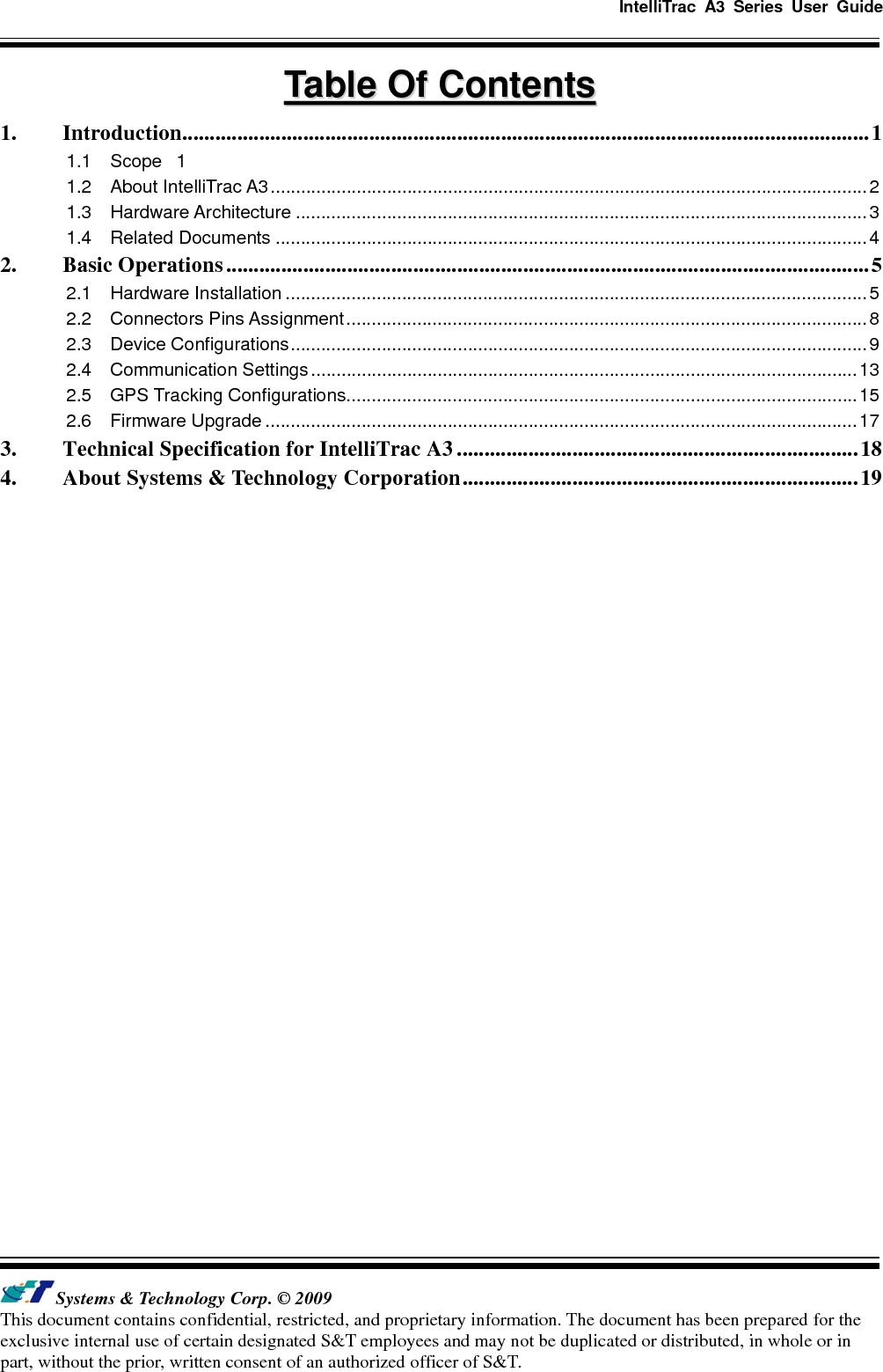
![IntelliTrac A3 Series User Guide Systems & Technology Corp. © 2009 This document contains confidential, restricted, and proprietary information. The document has been prepared for the exclusive internal use of certain designated S&T employees and may not be duplicated or distributed, in whole or in part, without the prior, written consent of an authorized officer of S&T. - 10 - (4) Choose [File]Æ[Properties] and click [ASCII Setup…] (5) Checked below ASCII Sending options](https://usermanual.wiki/Systems-and-Technology/STAVL0941/User-Guide-1232233-Page-13.png)
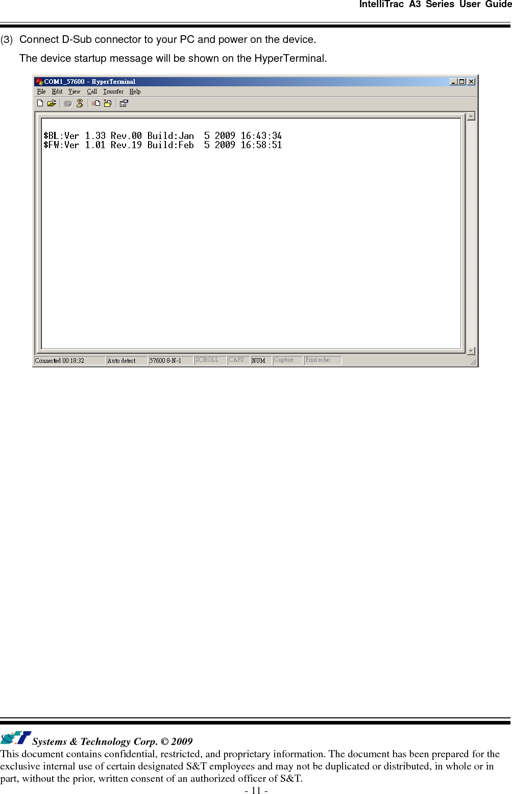
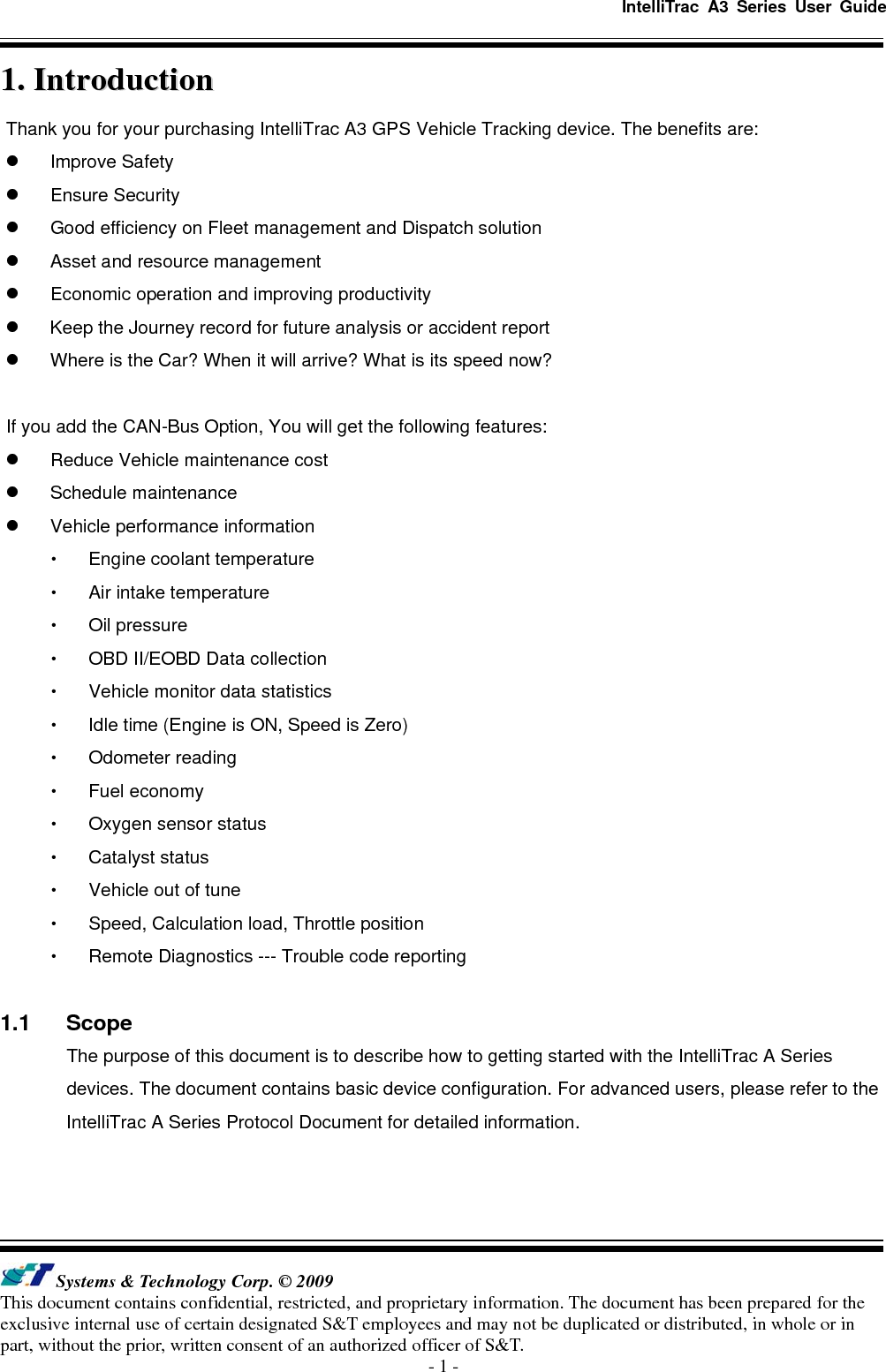
![IntelliTrac A3 Series User Guide Systems & Technology Corp. © 2009 This document contains confidential, restricted, and proprietary information. The document has been prepared for the exclusive internal use of certain designated S&T employees and may not be duplicated or distributed, in whole or in part, without the prior, written consent of an authorized officer of S&T. - 12 - (4) Type ATI command and press [Enter] key, the hardware and firmware version will be shown on the HyperTerminal. If the HyperTerminal is shown like below, that means connection between the device and PC is working properly. It is ready to send all configuration commands from now on.](https://usermanual.wiki/Systems-and-Technology/STAVL0941/User-Guide-1232233-Page-15.png)
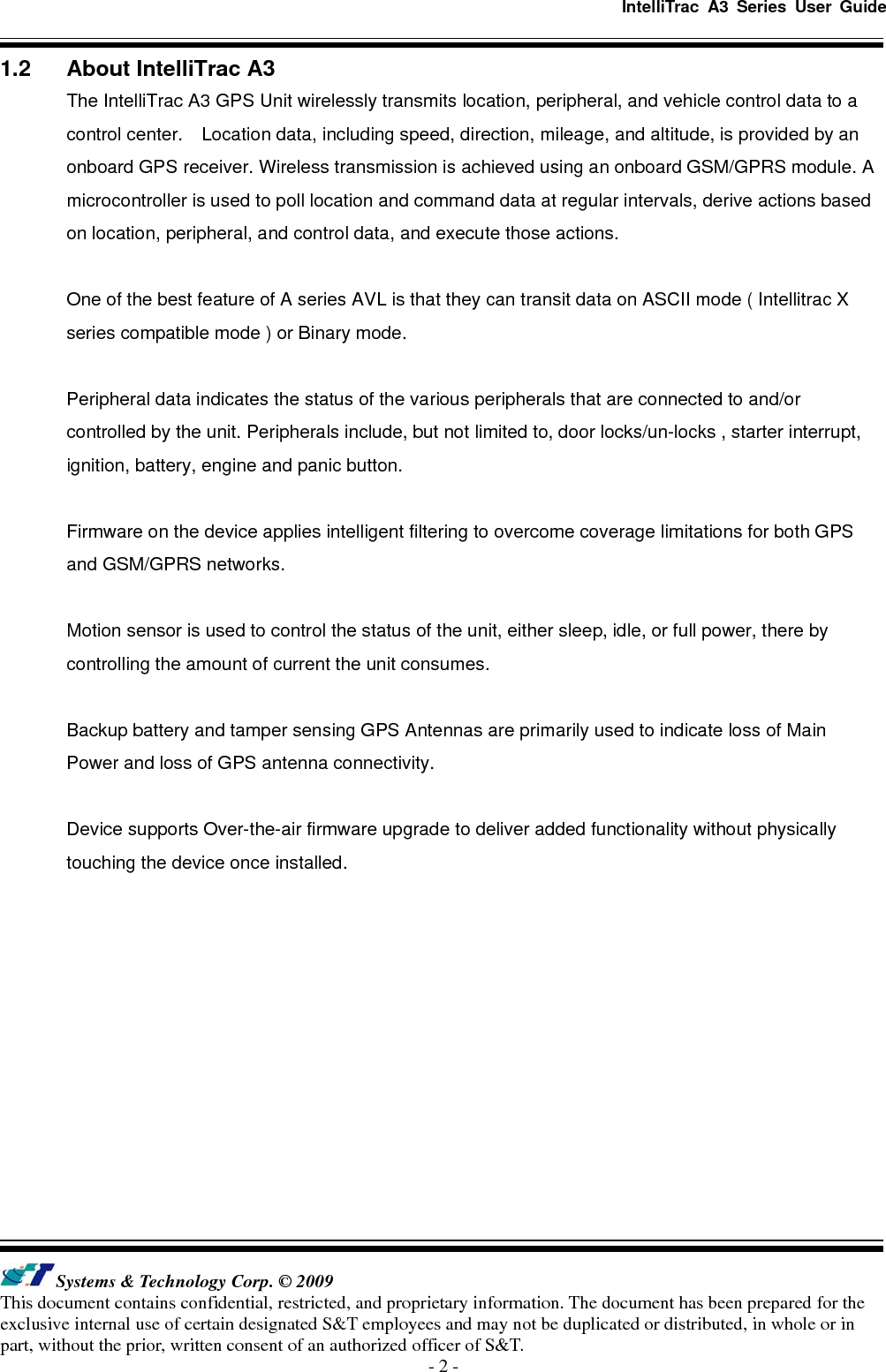
![IntelliTrac A3 Series User Guide Systems & Technology Corp. © 2009 This document contains confidential, restricted, and proprietary information. The document has been prepared for the exclusive internal use of certain designated S&T employees and may not be duplicated or distributed, in whole or in part, without the prior, written consent of an authorized officer of S&T. - 17 - 2.6 Firmware Upgrade The IntelliTrac A Series device firmware is updated through the serial interface. The firmware update of the device can be performed with the IntelliTrac A series firmware loader tool provided by S&T. It runs on Windows based PCs. Please see the following step-by-step upgrade procedure. (1) Connect the RS232 cable between device an PC. (2) Turn on the device. (3) Run AseriesLoader.exe, the following window is displayed. (4) Click […] button to open firmware file which provide by S&T (5) Click Write button and start firmware programming. (6) When the writing progress 100% is reached, the device LEDs will start to fast blinking. (7) Wait until device LEDs stop fast blinking. (8) Firmware update complete.](https://usermanual.wiki/Systems-and-Technology/STAVL0941/User-Guide-1232233-Page-20.png)