Systems and Technology STAVL1007 INTELLITRAC User Manual A1 LITE User Guide 001
Systems & Technology Corp. INTELLITRAC A1 LITE User Guide 001
Users Manual
Systems & Technology Corp. © 2010
This document contains confidential, restricted, and proprietary information. The document has been prepared for the
exclusive internal use of certain designated S&T employees and may not be duplicated or distributed, in whole or in
part, without the prior, written consent of an authorized officer of S&T.
I
In
nt
te
el
ll
li
iT
Tr
ra
ac
c
A
A1
1-
-l
li
it
te
e
S
Se
er
ri
ie
es
s
U
Us
se
er
r
G
Gu
ui
id
de
e
Version: V0.1
Date: 26 May 2010
Status: Preliminary

Systems & Technology Corp. © 2010
This document contains confidential, restricted, and proprietary information. The document has been prepared for the
exclusive internal use of certain designated S&T employees and may not be duplicated or distributed, in whole or in
part, without the prior, written consent of an authorized officer of S&T.
General notes
With respect to any damages arising in operation with the described product or this document, S&T shall be
liable according to the General Conditions on which the delivery of the described product and this document
are based. This product is not intended for use in life support appliances, devices or systems where a
malfunction of the product can reasonably be expected to result in personal injury. S&T customers using or
selling this product for use in such applications do so at their own risk and agree to fully indemnify S&T for
any damages resulting from illegal use or resale.
Information in this document is subject to change without notice at any time.
Copyright notice
Copying of this document and giving it to others and the use or communication of the contents thereof, are
forbidden without express authority. Offenders are liable to the payment of damages.
© Systems & Technology Corp. All rights reserved

IntelliTrac A1-lite Series User Guide
Systems & Technology Corp. © 2010
This document contains confidential, restricted, and proprietary information. The document has been prepared for the
exclusive internal use of certain designated S&T employees and may not be duplicated or distributed, in whole or in
part, without the prior, written consent of an authorized officer of S&T.
T
Ta
ab
bl
le
e
O
Of
f
C
Co
on
nt
te
en
nt
ts
s
1. Introduction.............................................................................................................................1
1.1
Scope ........................................................................................................................................1
1.2
About IntelliTrac A1-lite ................................................................................................................2
1.3
Hardware Architecture .................................................................................................................3
1.4
Related Documents .....................................................................................................................4
2. Basic Operations.....................................................................................................................4
2.1
Hardware Installation ...................................................................................................................4
2.2
Connectors Pins Assignment.......................................................................................................6
2.3
Device Configurations..................................................................................................................7
2.4
Communication Settings ............................................................................................................ 11
2.5
GPS Tracking Configurations.....................................................................................................13
2.6
Firmware Upgrade .....................................................................................................................15
3. Technical Specification for IntelliTrac A1-lite...................................................................16
4. About Systems & Technology Corporation........................................................................17

IntelliTrac A1-lite Series User Guide
Systems & Technology Corp. © 2010
This document contains confidential, restricted, and proprietary information. The document has been prepared for the
exclusive internal use of certain designated S&T employees and may not be duplicated or distributed, in whole or in
part, without the prior, written consent of an authorized officer of S&T.
- 1 -
1
1.
.I
In
nt
tr
ro
od
du
uc
ct
ti
io
on
n
Thank you for your purchasing IntelliTrac A1-lite GPS Vehicle Tracking device. The benefits are:
Improve Safety
Ensure Security
Good efficiency on Fleet management and Dispatch solution
Asset and resource management
Economic operation and improving productivity
Keep the Journey record for future analysis or accident report
Where is the Car? When it will arrive? What is its speed now?
1.1 Scope
The purpose of this document is to describe how to getting started with the IntelliTrac A Series
devices. The document contains basic device configuration. For advanced users, please refer to the
IntelliTrac A Series Protocol Document for detailed information.

IntelliTrac A1-lite Series User Guide
Systems & Technology Corp. © 2010
This document contains confidential, restricted, and proprietary information. The document has been prepared for the
exclusive internal use of certain designated S&T employees and may not be duplicated or distributed, in whole or in
part, without the prior, written consent of an authorized officer of S&T.
- 2 -
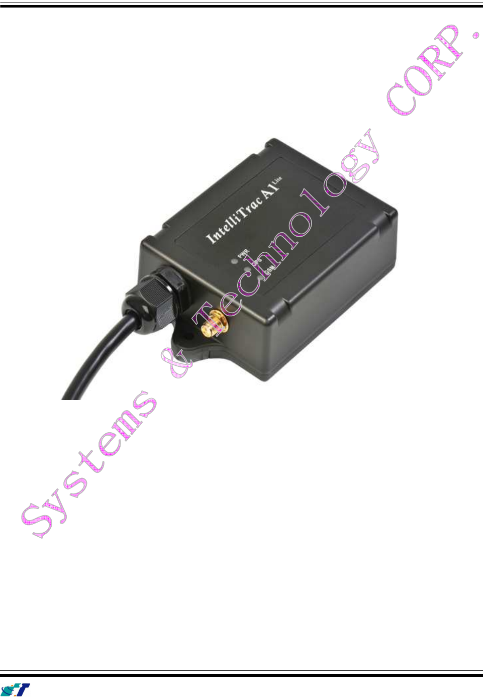
1.2 About IntelliTrac A1-lite
The IntelliTrac A1-lite GPS Unit wirelessly transmits location, peripheral, and vehicle control data to
a control center. Location data, including speed, direction, mileage, and altitude, is provided by an
onboard GPS receiver. Wireless transmission is achieved using an onboard GSM/GPRS module. A
microcontroller is used to poll location and command data at regular intervals, derive actions based
on location, peripheral, and control data, and execute those actions.
One of the best feature of A series AVL is that they can transit data on ASCII mode or Binary mode.
Peripheral data indicates the status of the various peripherals that are connected to and/or
controlled by the unit. Peripherals include, but not limited to, door locks/un-locks , starter interrupt,
ignition, battery, engine and panic button.
Firmware on the device applies intelligent filtering to overcome coverage limitations for both GPS
and GSM/GPRS networks.
Motion sensor is used to control the status of the unit, either sleep, idle, or full power, there by
controlling the amount of current the unit consumes.
Backup battery and tamper sensing GPS Antennas are primarily used to indicate loss of Main
Power and loss of GPS antenna connectivity.
Device supports Over-the-air firmware upgrade to deliver added functionality without physically
touching the device once installed.
IntelliTrac A1-lite Series User Guide
Systems & Technology Corp. © 2010
This document contains confidential, restricted, and proprietary information. The document has been prepared for the
exclusive internal use of certain designated S&T employees and may not be duplicated or distributed, in whole or in
part, without the prior, written consent of an authorized officer of S&T.
- 3 -
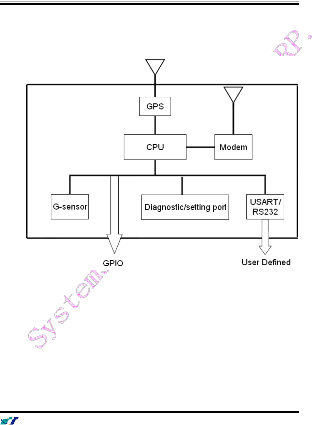
1.3 Hardware Architecture
The IntelliTrac A1-lite hardware includes Micro-controller, GPS receiver, GSM/GPRS modem,
G-Force sensor, I/Os interfac.
.
User can use PC HyperTerminal connect to the Diagnostic / setting port to configure the AVL.
The G-Sensor is used for car accident. Car tow-away warning and power management.
GPIO can be used to connect to any customer monitoring points (door switch, anti-thief) or
Actuators.
RS232 Expansion port .
RTOS OPTION: We will have A1, A3 professional version with Real Time operation system in
JAN.2010.
IntelliTrac A1-lite Series User Guide
Systems & Technology Corp. © 2010
This document contains confidential, restricted, and proprietary information. The document has been prepared for the
exclusive internal use of certain designated S&T employees and may not be duplicated or distributed, in whole or in
part, without the prior, written consent of an authorized officer of S&T.
- 4 -
1.4 Related Documents
[1] IntelliTrac A Series Protocol Document Basic Operations
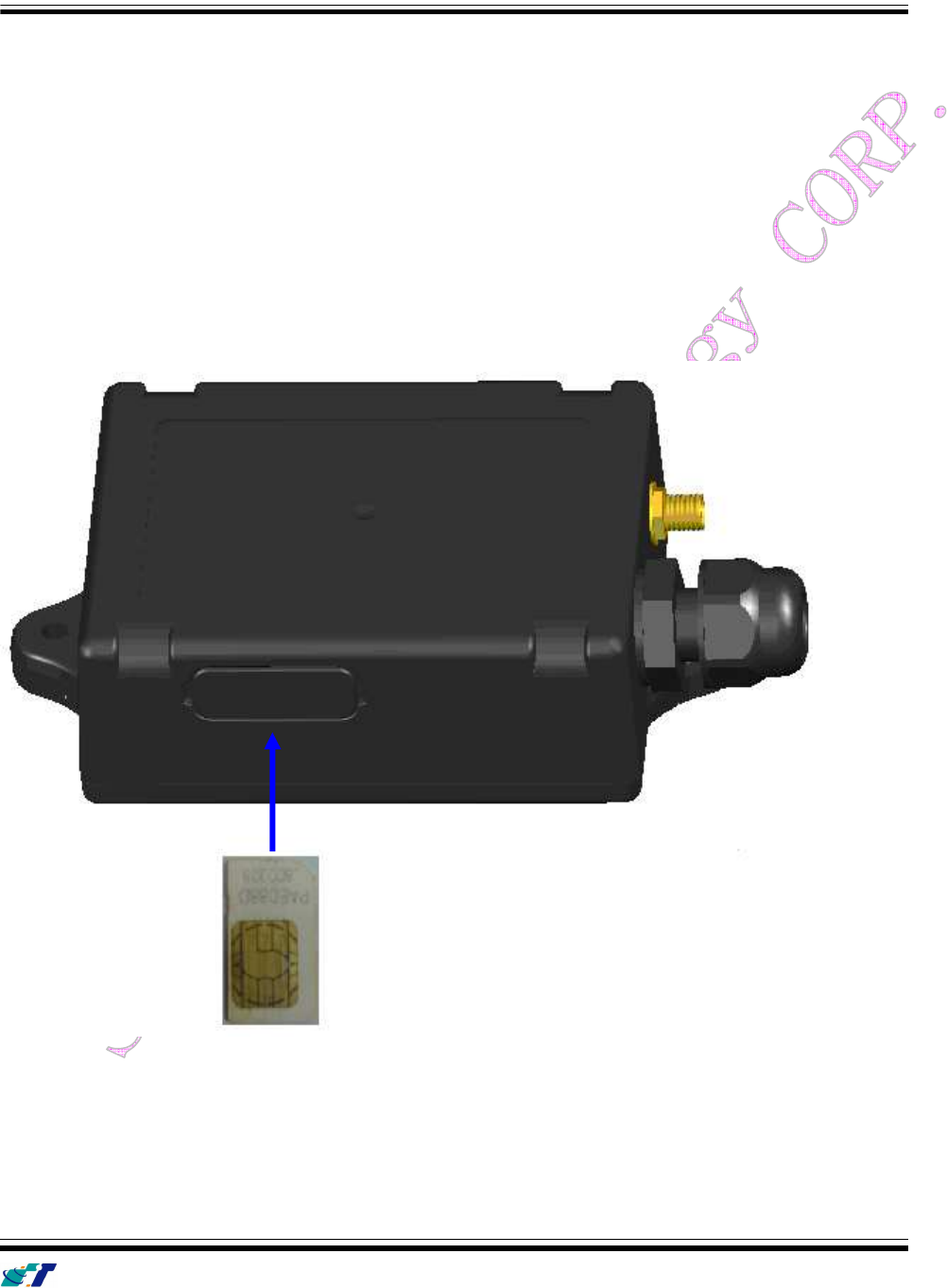
1.5 Hardware Installation
(1) SIM Card Installation
Press yellow button to eject the SIM card holder.
Put the SIM card on the SIM card holder.
Insert the SIM card holder to the device correctly.
IntelliTrac A1-lite Series User Guide
Systems & Technology Corp. © 2010
This document contains confidential, restricted, and proprietary information. The document has been prepared for the
exclusive internal use of certain designated S&T employees and may not be duplicated or distributed, in whole or in
part, without the prior, written consent of an authorized officer of S&T.
- 5 -
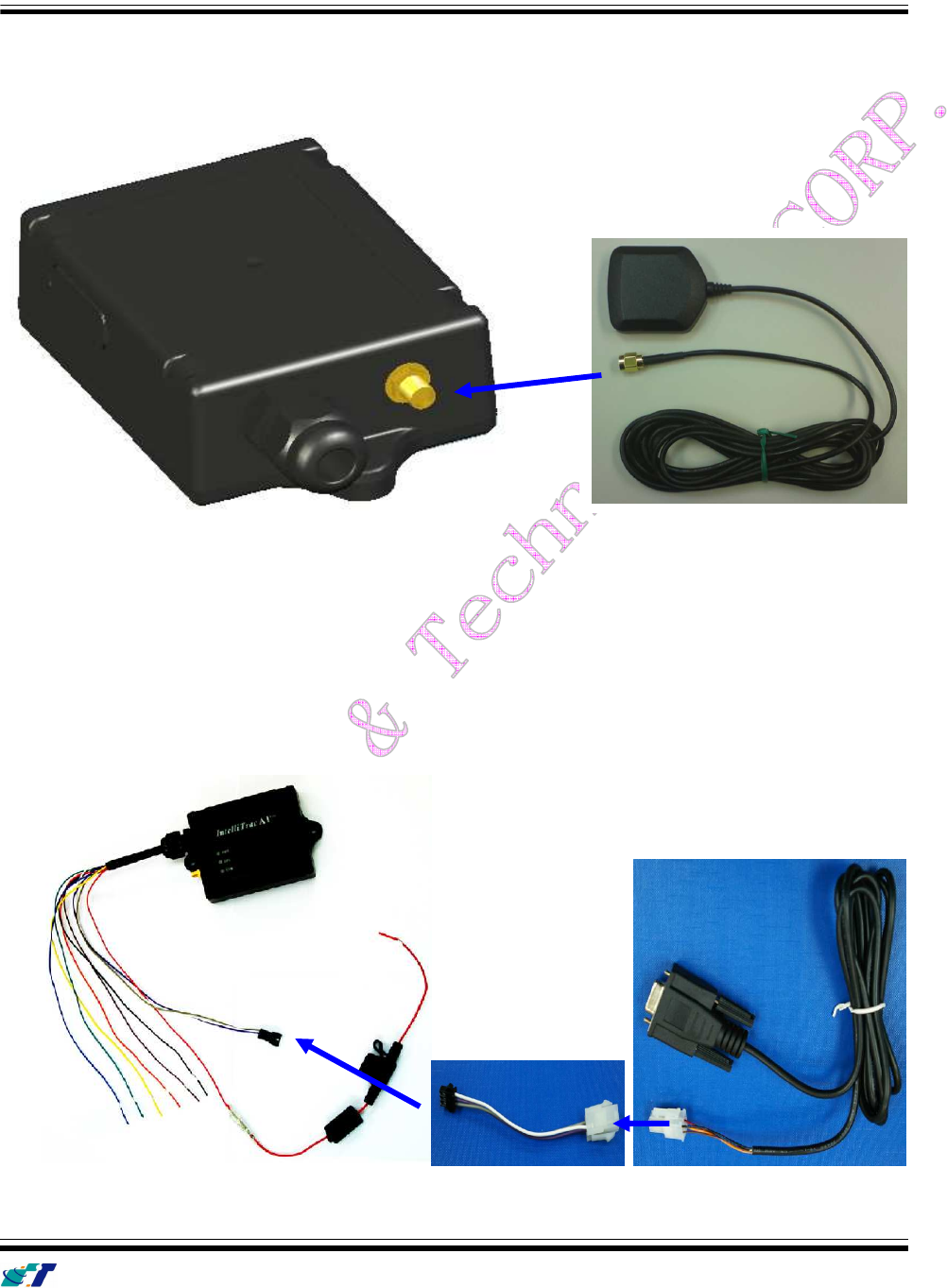
(2) GPS Antenna Installation
Connect the GPS antenna to the right-down corner SMA connector.
Recommended mating torque for the SMA connector is 7-10 inch pounds (80-110 N.cm).
(3) Power,RS-232 and I/O Cable Installation
Connect 4-wires power cable to the device, The D-SUB can be connected to the COM port of PC.
Connect 8-wires cable to the device. And plug on a DC power supply (8~30V) and I/O.
IntelliTrac A1-lite Series User Guide
Systems & Technology Corp. © 2010
This document contains confidential, restricted, and proprietary information. The document has been prepared for the
exclusive internal use of certain designated S&T employees and may not be duplicated or distributed, in whole or in
part, without the prior, written consent of an authorized officer of S&T.
- 6 -
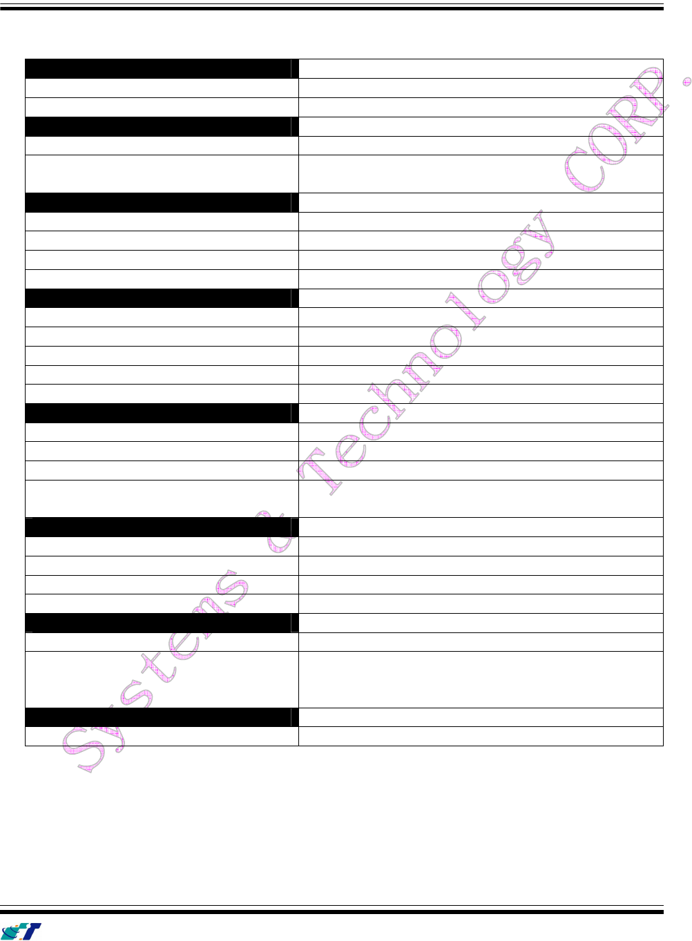
1.6 Connectors Pins Assignment
PWR / IO Connector
Pin#
Signal Name Description IO
Electrical Characteristic
1 DC IN Red I V
I
= DC8 to 30V, Inormal = 70mA @12V
2 GND Black -
3 Ignition Brown I V
IH
min = 30V, V
IL
max = 6.8V(High Active)
4 Output1 Orange O Imax = 300mA
5 Input1 Yellow I V
IH
max = 30V, V
IL
max = 0.7V
6 Output2 Green O Imax = 300mA
SERIAL Connector
Pin#
Signal Name Description IO
Electrical Characteristic
1 Vout Blue O Vo = 5.0V, Imax = 250mA
2 TX1 Purple O
3 RX1 Gray I
4 GND White -
Connectors pin definition
IntelliTrac A1-lite Series User Guide
Systems & Technology Corp. © 2010
This document contains confidential, restricted, and proprietary information. The document has been prepared for the
exclusive internal use of certain designated S&T employees and may not be duplicated or distributed, in whole or in
part, without the prior, written consent of an authorized officer of S&T.
- 7 -
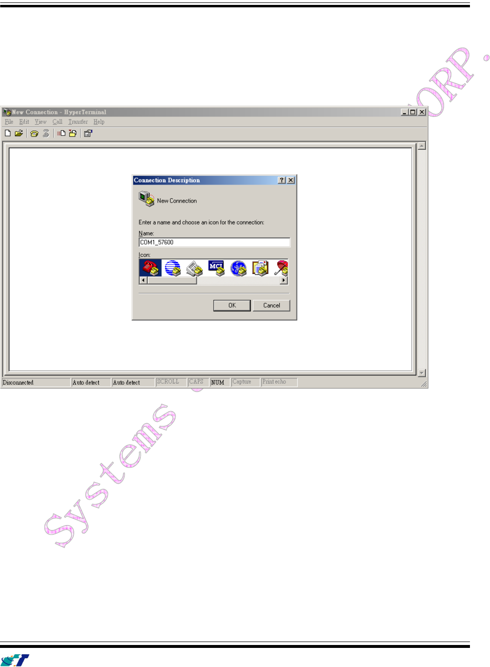
Device Configurations
For the first installation, some basic parameters should be set before installation. The device parameters
can be set through RS-232 port by using HyperTerminal program. Please see below for the HyperTerminal
settings:
(1) Open HyperTerminal
(2) Choose correct COM port
(3) Baud Rate57600bps, Data Bits8, ParityNone, Stop Bits1, Flow ControlNone
IntelliTrac A1-lite Series User Guide
Systems & Technology Corp. © 2010
This document contains confidential, restricted, and proprietary information. The document has been prepared for the
exclusive internal use of certain designated S&T employees and may not be duplicated or distributed, in whole or in
part, without the prior, written consent of an authorized officer of S&T.
- 8 -
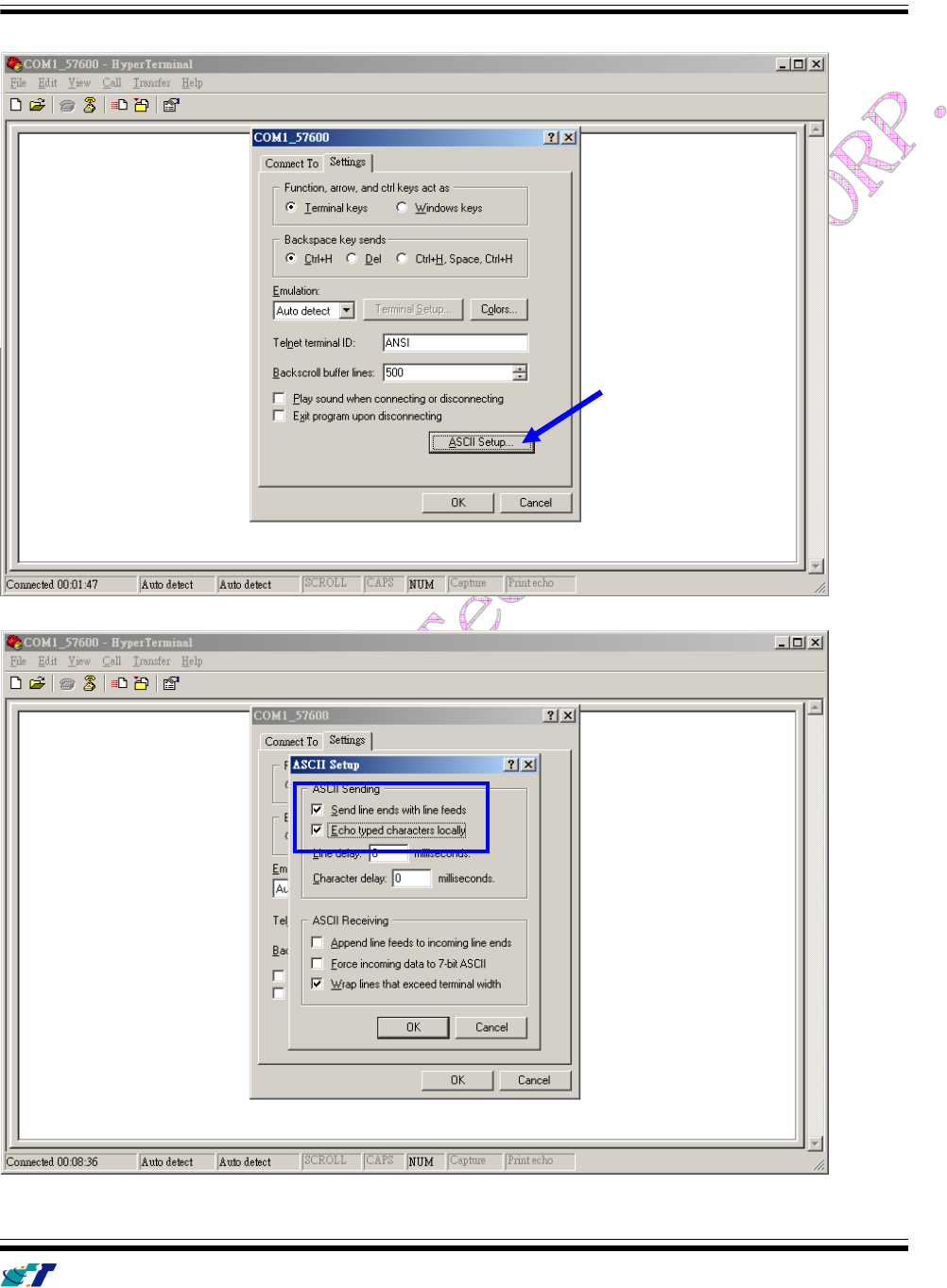
(4) Choose [File][Properties] and click [ASCII Setup…]
(5) Checked below ASCII Sending options
IntelliTrac A1-lite Series User Guide
Systems & Technology Corp. © 2010
This document contains confidential, restricted, and proprietary information. The document has been prepared for the
exclusive internal use of certain designated S&T employees and may not be duplicated or distributed, in whole or in
part, without the prior, written consent of an authorized officer of S&T.
- 9 -
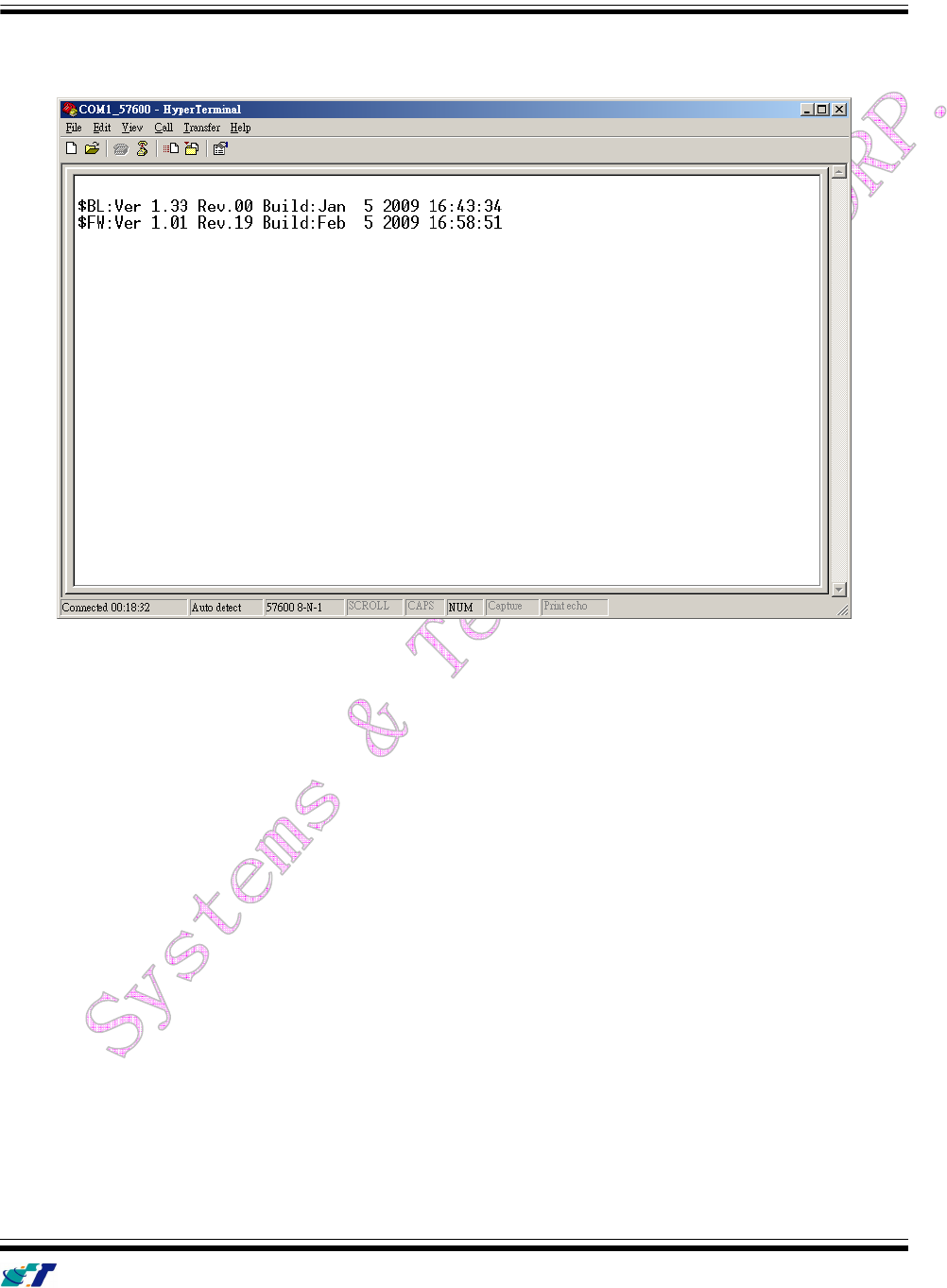
(4) Connect D-Sub connector to your PC and power on the device.
The device startup message will be shown on the HyperTerminal.
IntelliTrac A1-lite Series User Guide
Systems & Technology Corp. © 2010
This document contains confidential, restricted, and proprietary information. The document has been prepared for the
exclusive internal use of certain designated S&T employees and may not be duplicated or distributed, in whole or in
part, without the prior, written consent of an authorized officer of S&T.
- 10 -
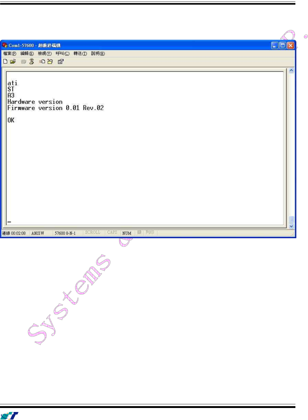
(5) Type ATI command and press [Enter] key, the hardware and firmware version will be shown on the
HyperTerminal. If the HyperTerminal is shown like below, that means connection between the device
and PC is working properly. It is ready to send all configuration commands from now on.

IntelliTrac A1-lite Series User Guide
Systems & Technology Corp. © 2010
This document contains confidential, restricted, and proprietary information. The document has been prepared for the
exclusive internal use of certain designated S&T employees and may not be duplicated or distributed, in whole or in
part, without the prior, written consent of an authorized officer of S&T.
- 11 -
Communication Settings
There are two communication modes for the IntelliTrac A series device to communicate to the control center.
One is SMS, and the other is GPRS (TCP/UDP). The device should be set communication parameters
before install the device to vehicle.
(1) SMS Configuration
Setting SMS control center phone number or short code by using AT$SMSDST command. For example,
the SMS control center phone number is +886123456789, issue the AT$SMSDST command in
HyperTerminal like below:
AT$SMSDST=+886123456789
OK
Then you can try to use cellular phone or SMS gateway to send a SMS message to the A1 device.
Send a SMS message "AT$MODID?"
Device will response:
$MODID=101000001
OK
(Type AT&W command to save all command parameters into the non-volatile memory of the device.)
AT&W
OK
This proves the mobile phone SMS connects successfully.

IntelliTrac A1-lite Series User Guide
Systems & Technology Corp. © 2010
This document contains confidential, restricted, and proprietary information. The document has been prepared for the
exclusive internal use of certain designated S&T employees and may not be duplicated or distributed, in whole or in
part, without the prior, written consent of an authorized officer of S&T.
- 12 -
(2) GPRS Configuration
Setting GPRS server using the following commands:
AT$APN=internet,username,password (APN=internet, Username=username, Password=password)
OK
AT$HOSTS=1,60.148.19.10 (Server IP address = 60.148.19.10)
OK
AT$RETRY=5,10 (Message retry settings)
OK
AT$IPTYPE=1 (Using TCP/IP mode)
OK
AT$PORT=6000 (Host application port)
OK
AT$GPRSEN=1 (GPRS enable)
OK
AT$HB=60 (Heartbeat setting)
OK
(Type AT&W command to save all command parameters into the non-volatile memory of the device.)
AT&W
OK
Please refer to IntelliTrac A Series Protocol Document for detailed command descriptions.
IntelliTrac A1-lite Series User Guide
Systems & Technology Corp. © 2010
This document contains confidential, restricted, and proprietary information. The document has been prepared for the
exclusive internal use of certain designated S&T employees and may not be duplicated or distributed, in whole or in
part, without the prior, written consent of an authorized officer of S&T.
- 13 -
GPS Tracking Configurations
After the device communication settings are done. The remote GPS tracking function can be performed.
The GPS tracking function can be set by using AT$PDSR command. For example,
AT$PDSR=1,30,0,2,0,0,1,1 (Tracking through GPRS by time interval 30 seconds)
OK
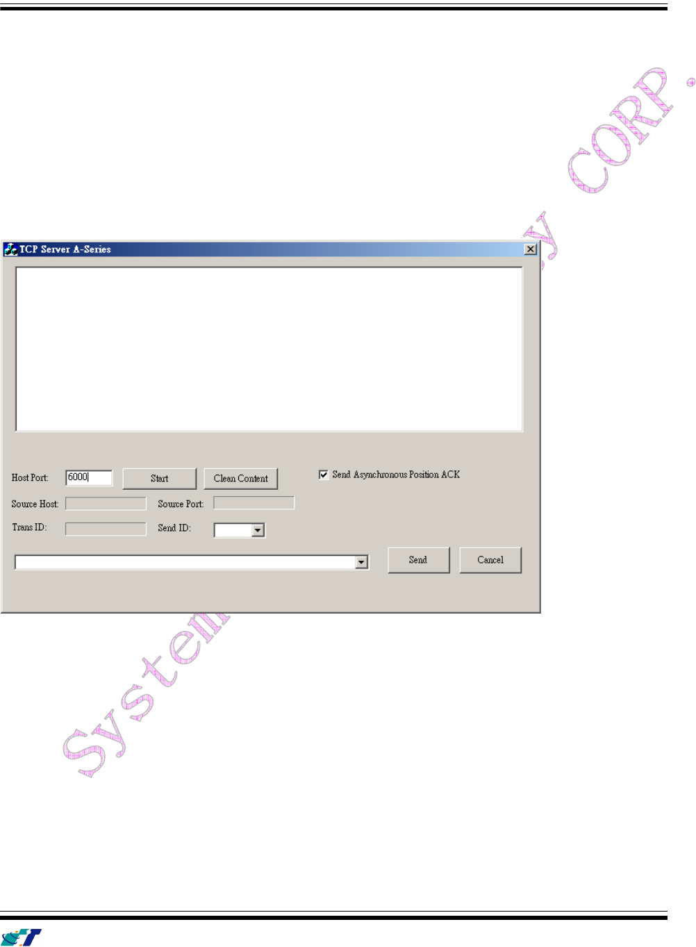
For the simply testing GPRS, open the TCP Server A-Series software which is provided by S&T. It is a
simple server software that can wait for device connection and data.
IntelliTrac A1-lite Series User Guide
Systems & Technology Corp. © 2010
This document contains confidential, restricted, and proprietary information. The document has been prepared for the
exclusive internal use of certain designated S&T employees and may not be duplicated or distributed, in whole or in
part, without the prior, written consent of an authorized officer of S&T.
- 14 -
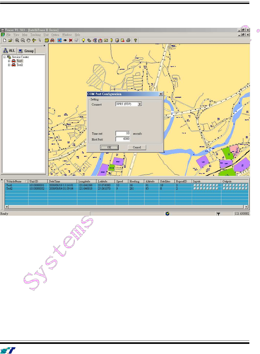
For advanced testing, open the IntelliTrac Tracer software and set communication port properly. The device
will start to connect to the Tracer software and report GPS tracking locations.
IntelliTrac A1-lite Series User Guide
Systems & Technology Corp. © 2010
This document contains confidential, restricted, and proprietary information. The document has been prepared for the
exclusive internal use of certain designated S&T employees and may not be duplicated or distributed, in whole or in
part, without the prior, written consent of an authorized officer of S&T.
- 15 -
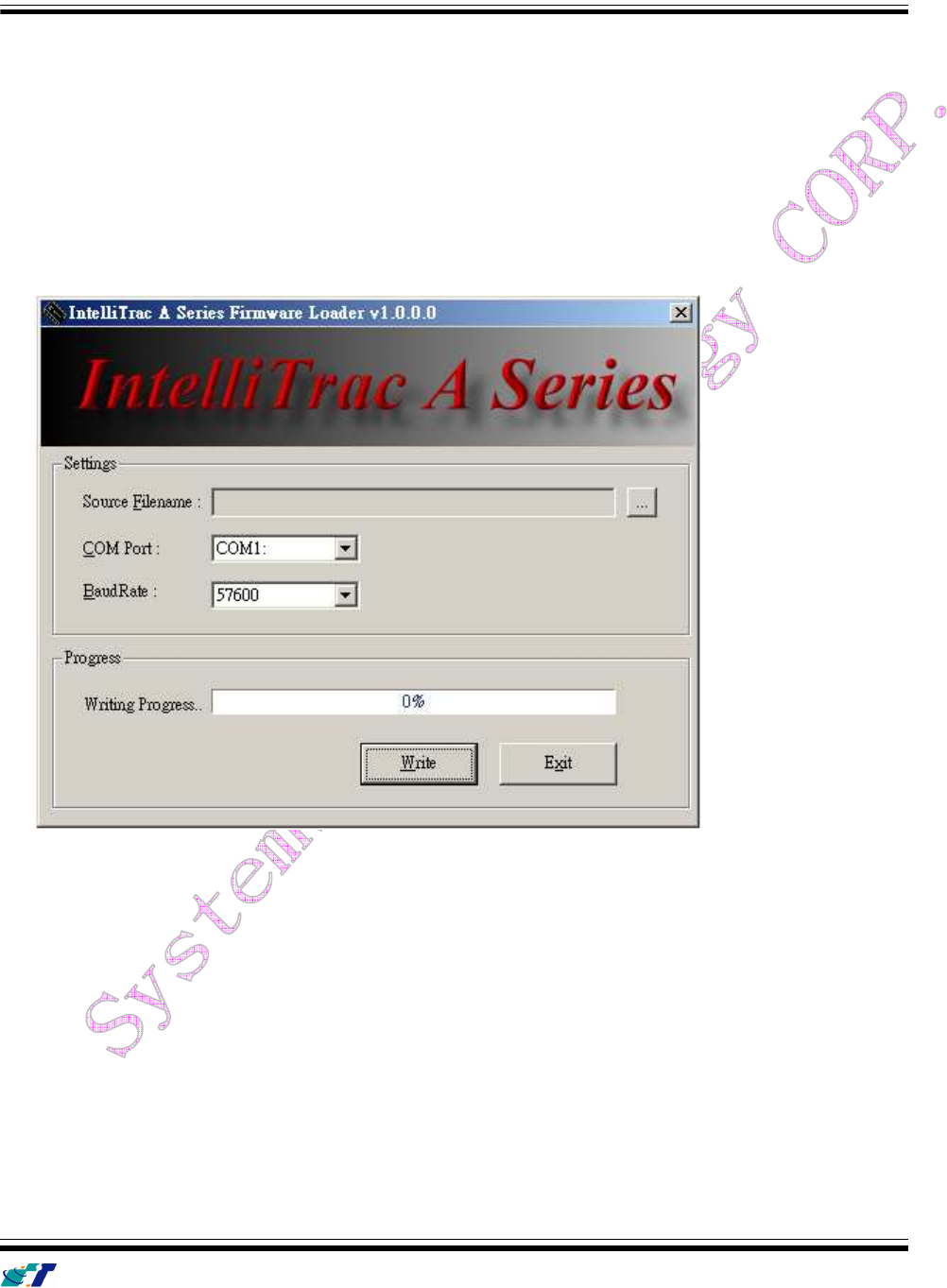
Firmware Upgrade
The IntelliTrac A Series device firmware is updated through the serial interface. The firmware update of the
device can be performed with the IntelliTrac A series firmware loader tool provided by S&T. It runs on
Windows based PCs. Please see the following step-by-step upgrade procedure.
(1) Connect the RS232 cable between device an PC.
(2) Turn on the device.
(3) Run AseriesLoader.exe, the following window is displayed.
(4) Click […] button to open firmware file which provide by S&T
(5) Click Write button and start firmware programming.
(6) When the writing progress 100% is reached, the device LEDs will start to fast blinking.
(7) Wait until device LEDs stop fast blinking.
(8) Firmware update complete.
IntelliTrac A1-lite Series User Guide
Systems & Technology Corp. © 2010
This document contains confidential, restricted, and proprietary information. The document has been prepared for the
exclusive internal use of certain designated S&T employees and may not be duplicated or distributed, in whole or in
part, without the prior, written consent of an authorized officer of S&T.
- 16 -
2
2.
.
T
Te
ec
ch
hn
ni
ic
ca
al
l
S
Sp
pe
ec
ci
if
fi
ic
ca
at
ti
io
on
n
f
fo
or
r
I
In
nt
te
el
ll
li
iT
Tr
ra
ac
c
A
A1
1-
-L
Li
it
te
e
CHARACTERISTICS
Dimensions ( L x W x H)
135 x 70 x 35mm
(With Connector)
Weight
170gm
Radio Performance
Frequency (MHz)
Quad-Band 850/900/1800/1900MHz
Transmit Power
1W/1800MHz,1900Mhz
2W/850MHz, 900MHz
GSM Functionality / GPRS
GPRS Mode MultiSlot Class 10/B , Mobile Station Class B
GPRS Coding Scheme
CS1,CS2,CS3 and CS4
GSM Antenna
Internal GSM Antenna
SIM Interface
Support SIM card 1.8V, 2.9V
GPS Functionality
Receiver
12 Channels or above
Sensitivity ( Tracking )
-159dBm
Antenna Type
External GPS Active Antenna , 3.3V
Connector
SMA Female
GPS Protocol
NMEA 0183 Ver3.0
Onboard Components
MCU
32-bit Microcontroller
Data Memory
2MB flash
Motion Sensor
3-Axes Acceleration Sensor
Led Indicator
3 , Green (Power status ) , Red ( GPS, GSM
status )
Interface I/O
I/O Connector
1Connectors. 4pin
Serial Data I/O
RS-232 (Default 57600bps)
Inputs
2
Outputs
2
Electrical
Power Source
DC 8V to 30V
Power Consumption
70mA @ 12V (Full power mode)
15mA @ 12V (Low power mode)
6mA @ 12V (Very low power mode)
Environment
Operating Temperature
-20
o
C to +70
o
C

IntelliTrac A1-lite Series User Guide
Systems & Technology Corp. © 2010
This document contains confidential, restricted, and proprietary information. The document has been prepared for the
exclusive internal use of certain designated S&T employees and may not be duplicated or distributed, in whole or in
part, without the prior, written consent of an authorized officer of S&T.
- 17 -
3
3.
.
A
Ab
bo
ou
ut
t
S
Sy
ys
st
te
em
ms
s
&
&
T
Te
ec
ch
hn
no
ol
lo
og
gy
y
C
Co
or
rp
po
or
ra
at
ti
io
on
n
IntelliTrac A-Series AVL device is produced by Systems & Technology Corporation. The company is a key
developer and supplier of advanced systems in the Automatic Vehicle Location (AVL), Digital Map and Car
Navigation Systems.
If you need information on other maps solutions or products, please contact us at the phone and fax
numbers listed below, or visit our web sites.
Contact Information for System & Technology Corp.
S&T Web Site http://www.systech.com.tw
Technical Support Hotline +886-2-2698-1599
Technical Support E-mail AVL@ms.systech.com.tw
Main Phone +886-2-2698-1599
Main Fax +886-2-2698-1211