Systems and Technology STAVL1321 2G/3.5G module, HE910-NAG, HE910-NAR, HE910-NAD User Manual U3
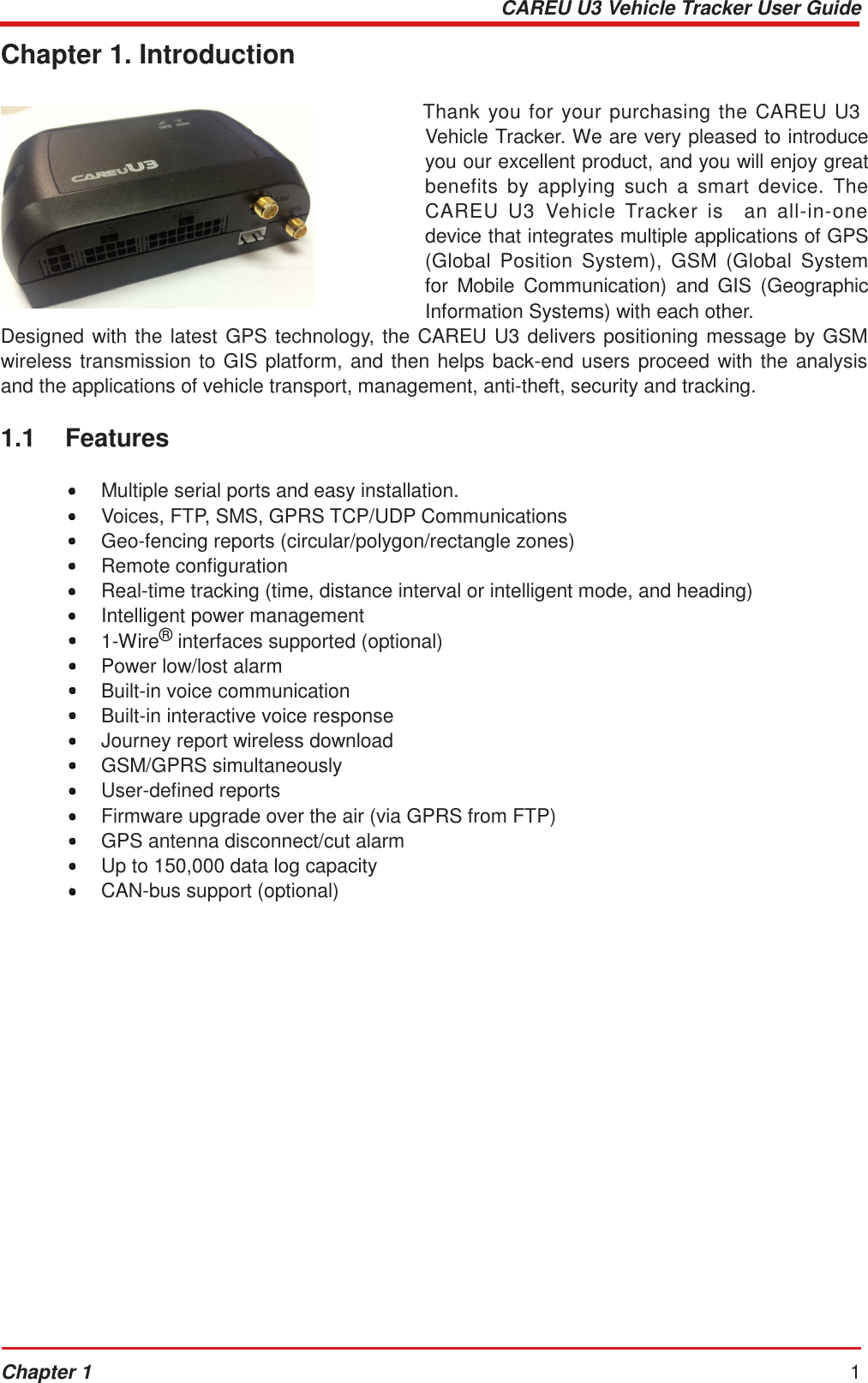
Systems & Technology Corp. 2G/3.5G module, HE910-NAG, HE910-NAR, HE910-NAD U3
UserManual.wiki
>
Systems and Technology
>
STAVL1321 User Manual
User manual
Navigation menu
Upload a User Manual
Namespaces
Wiki Guide
HTML
PDF
Info
Views
User Manual
Discussion / Help
Navigation
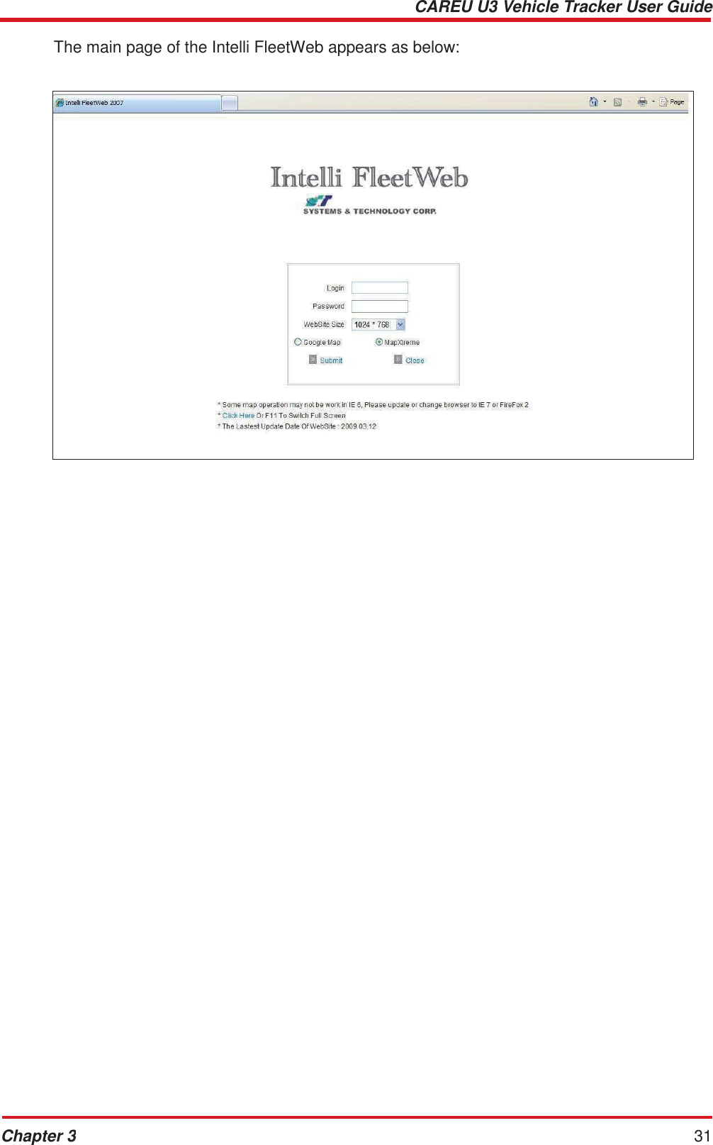
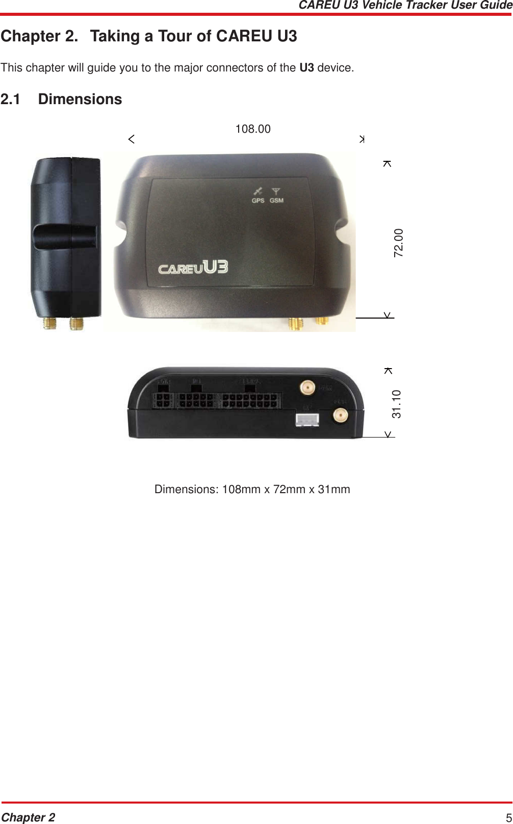
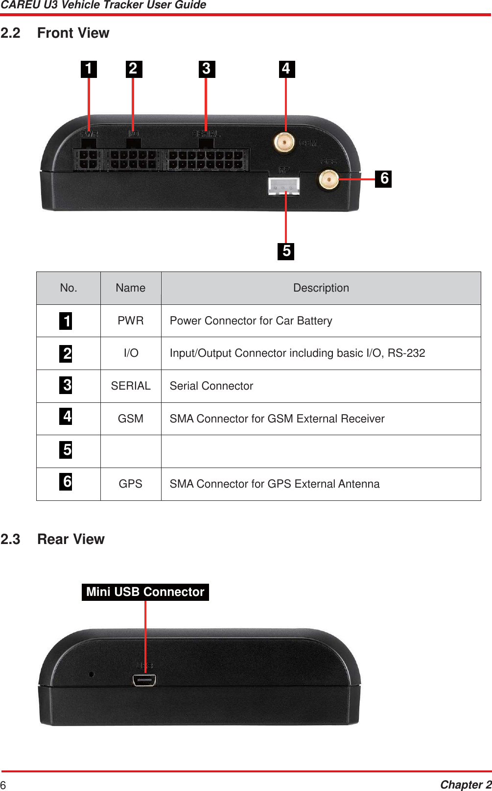
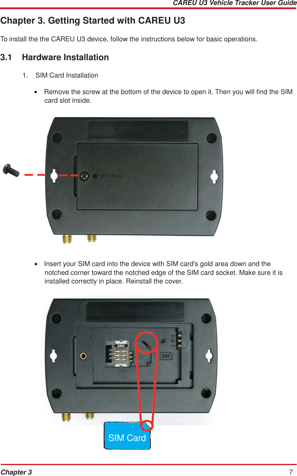
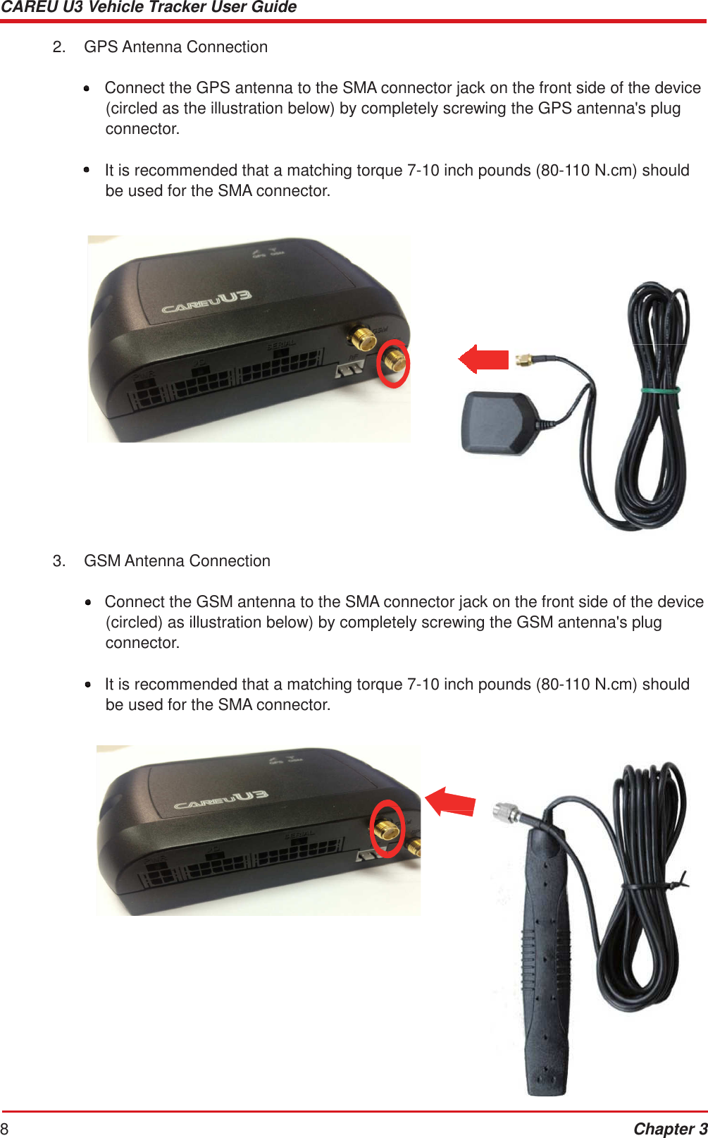
![CAREU U3 Vehicle Tracker User Guide 4 Chapter 1 1.5 Related Document [1] CAREU U3 Protocol Document](https://usermanual.wiki/Systems-and-Technology/STAVL1321/User-Guide-2163510-Page-8.png)
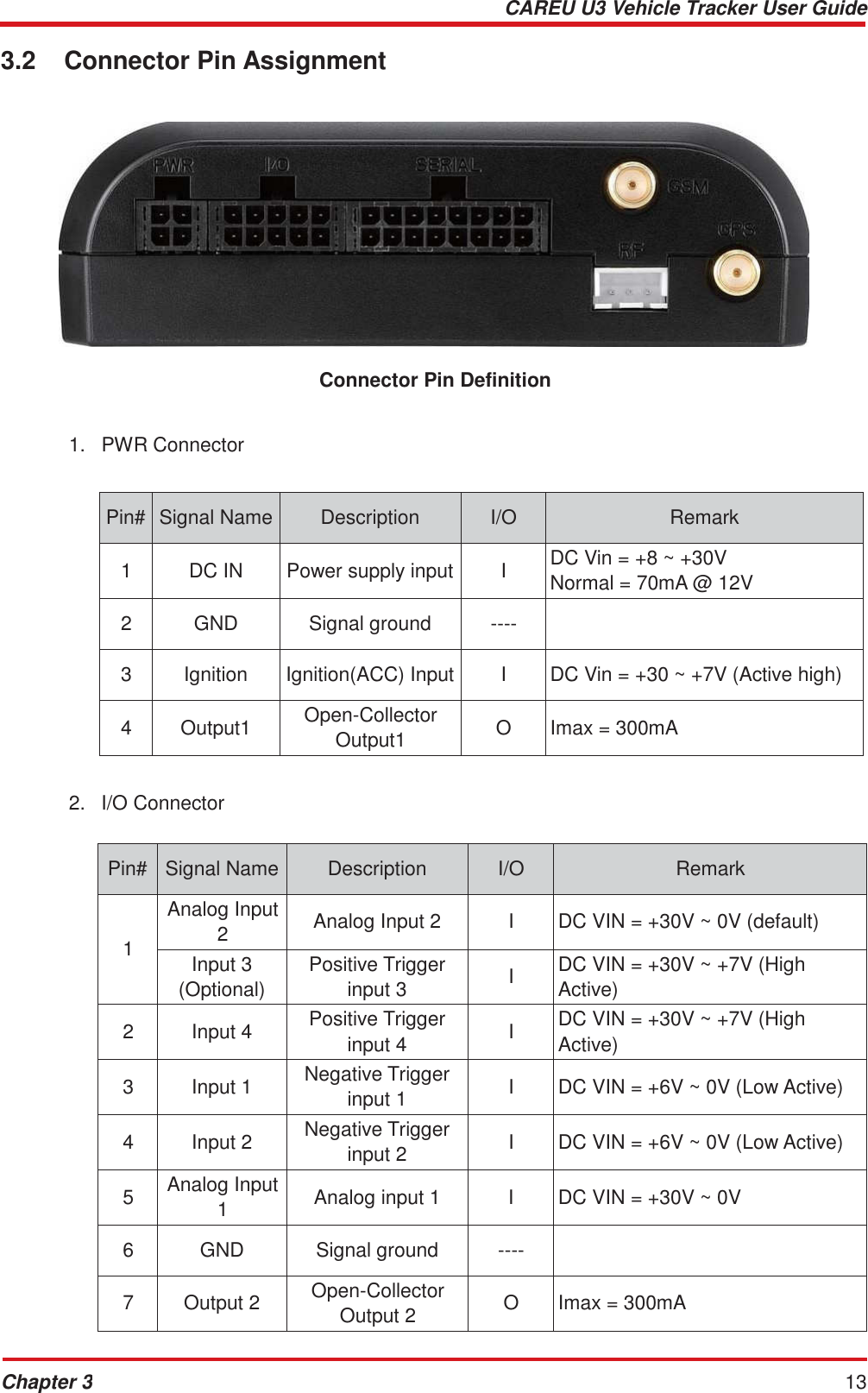
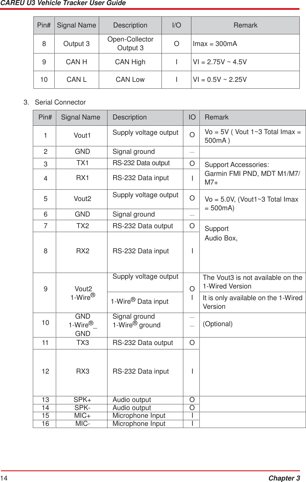

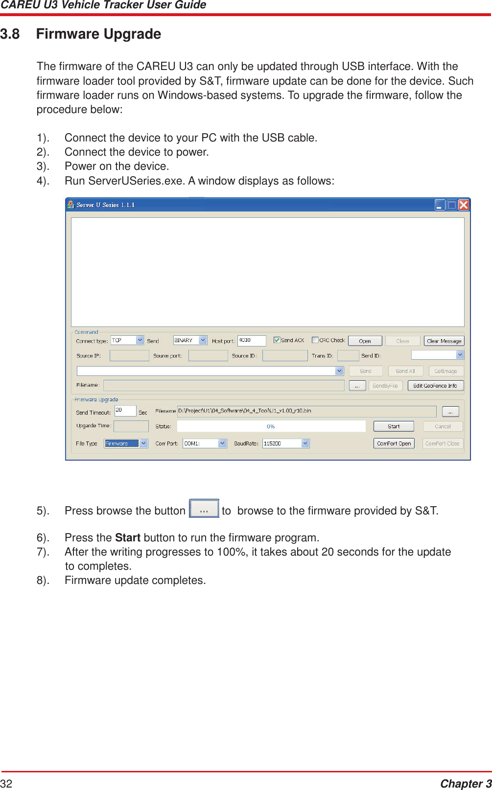
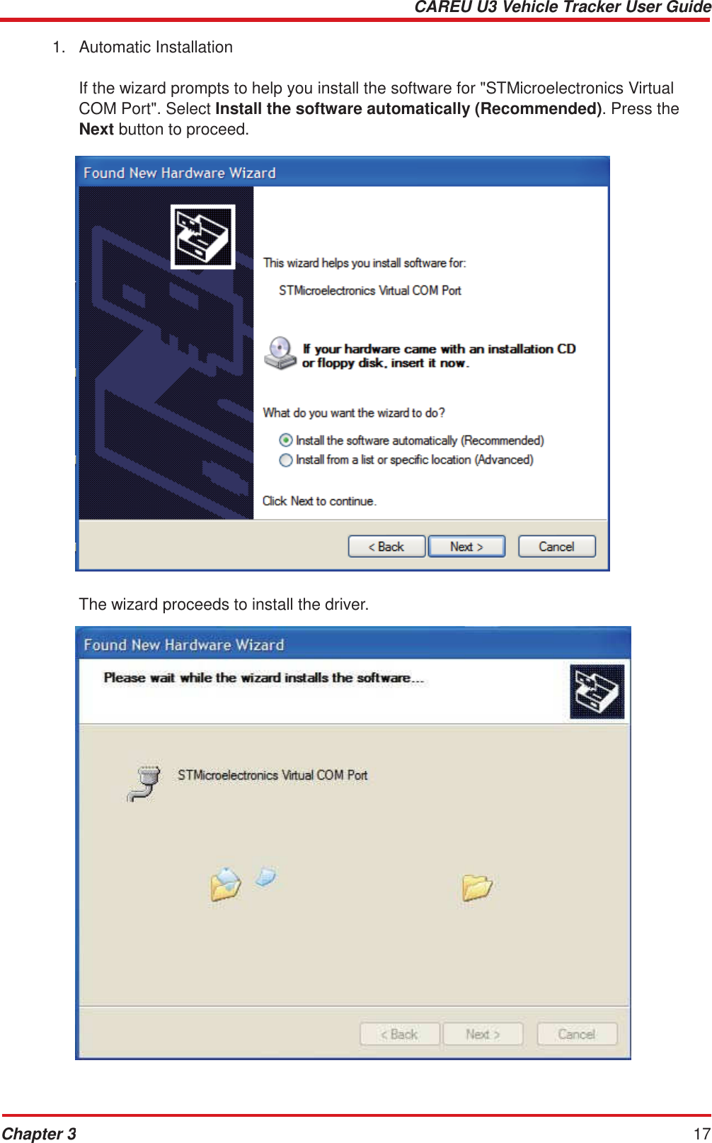
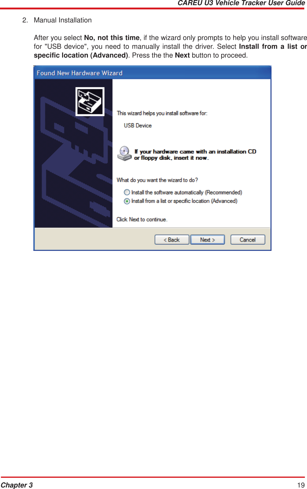
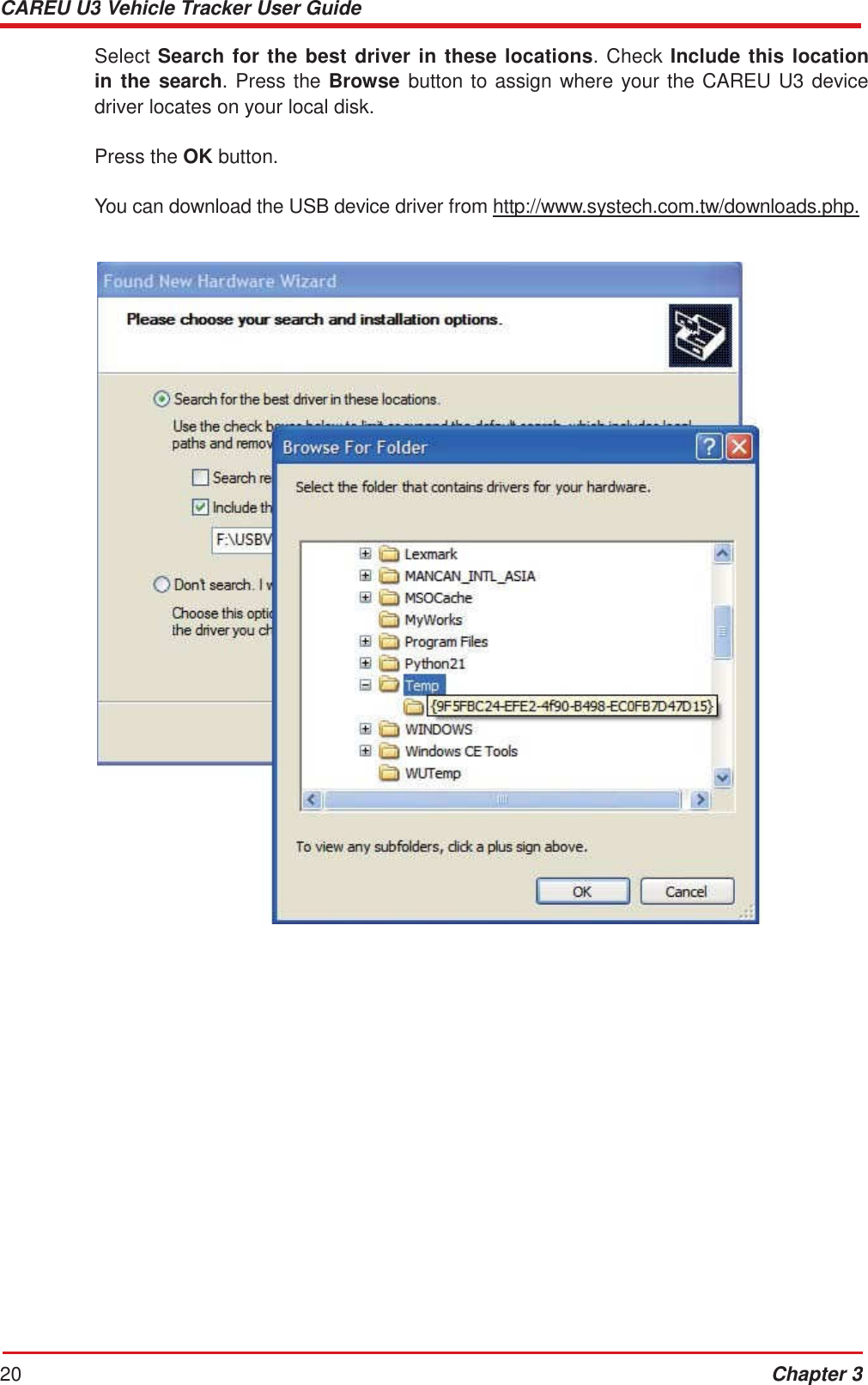
![CAREU U3 Vehicle Tracker User Guide 16 Chapter 3 3.4 USB Device Driver Installation The CAREU U3 communicates with your host computer by either RS-232 or USB interface. In some newer editions of Windows XP, the CAREU U3 device can be installed as a "virtual COM port" device whereby the CAREU U3 would automatically access Windows XP's inbox USB drivers. While in some other earlier editions of Windows XP, you would need to manually install the USB driver for the CAREU U3 device. In the following content of this section, you will be guided to how the installation can be done in both cases. To install the device driver for the CAREU U3, connect the CAREU U3 device to your system with an USB cable as mentioned in Mini USB Cable Connection on page 11. As soon as the connection is made between the CAREU U3 and your computer, a balloon appears above the notification area saying an USB device is found. Click on this balloon to start the [Found New Hardware] wizard. Select No, not this time. Press the Next button to proceed.](https://usermanual.wiki/Systems-and-Technology/STAVL1321/User-Guide-2163510-Page-20.png)
![CAREU U3 Vehicle Tracker User Guide 18 Chapter 3 The installation completes. In [Device Manager], the CAREU U3 device is included under Ports (COM & LPT) as "STMicroelectronics Virtual COM Port". COM port number is displayed as well.](https://usermanual.wiki/Systems-and-Technology/STAVL1321/User-Guide-2163510-Page-22.png)
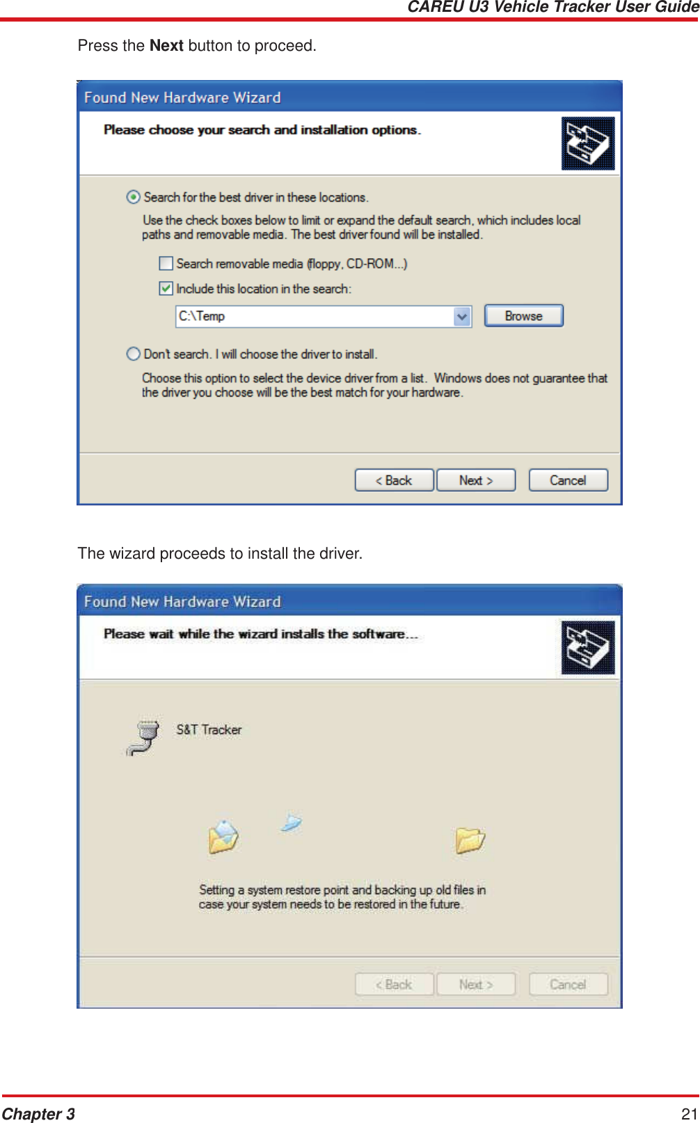
![CAREU U3 Vehicle Tracker User Guide 22 Chapter 3 The installation completes. In [Device Manager], the CAREU U3 device is included under Ports (COM & LPT) as "S&T Tracker". COM port number is displayed as well.](https://usermanual.wiki/Systems-and-Technology/STAVL1321/User-Guide-2163510-Page-26.png)
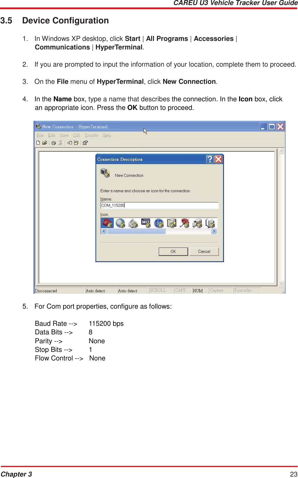
![CAREU U3 Vehicle Tracker User Guide 24 Chapter 3 6. In the connection that you have just set up, click File | Properties. Select the [Connect To] tab. From the [Connect using] drop down list, select the correct com port by checking it up at Windows XP's [DeviceManager] as previously mentioned on page 29 and page 33. Go there by clicking Start | Control Panel | System | Hardware | Device Manager.](https://usermanual.wiki/Systems-and-Technology/STAVL1321/User-Guide-2163510-Page-28.png)
![CAREU U3 Vehicle Tracker User Guide Chapter 3 25 7. In the File menu, click Properties. Click the [Settings] tab. Press the ASCII Setup button. 8. In the [ASCII Sending] group box. Select both Send line ends with line feeds and Echo typed characters locally. Press the OK button.](https://usermanual.wiki/Systems-and-Technology/STAVL1321/User-Guide-2163510-Page-29.png)
![CAREU U3 Vehicle Tracker User Guide 26 Chapter 3 9. Connect your the CAREU U3 device to power as mentioned in Power, RS-232, and I/O Cable Connection on page 9. The device startup message will be displayed. 10. In [HyperTerminal] window, type in the command "AT$VERSION?" and press the Enter key. The hardware and firmware version will show. As long as your [HyperTerminal] window appears as the screenshot below, a connection between the device and your system has already been built up and working. It is time to send all configuration commands.](https://usermanual.wiki/Systems-and-Technology/STAVL1321/User-Guide-2163510-Page-30.png)