Systems and Technology STAVL1321 2G/3.5G module, HE910-NAG, HE910-NAR, HE910-NAD User Manual U3
Systems & Technology Corp. 2G/3.5G module, HE910-NAG, HE910-NAR, HE910-NAD U3
User manual

CAREU
U3
Vehicle Tracker
User Guide
Version: 0.1
Reference No.: AVL-CU-U3-00-1115UEN
Date: July 10, 2013
SYSTEMS & TECHNOLOGY
CORP.
General Information
If any breakdown occurs due to the operation of the described product or users’ improper handling
in accordance with the instructions of the document, S&T shall be liable for the General Conditions
based on the delivery of the described product and the content of the document. This product is not
designed for the use of life support appliances, devices or systems and thence a malfunction of the
product might reasonably be expected to make personal injury. S&T customers using or selling this
product for such applications will take the risk on their own; therefore, it must be agreed S&T will
be fully indemnified from any damages due to illegal use or resale. All information in this document
is subject to change without notice at any time.
Disclaimer
The information, specification, images and photos in this user guide are subject to change without
notice and without obligation to notify any person of such revision change.
Copyright
This user guide, including all photographs, illustrations and software, to name a few, is protected
under international copyright laws, with all rights reserved. This document contains confidential,
restricted and proprietary information that it has been exclusively prepared for the internal use of
certain designated S&T employees, and may not be duplicated or distributed, in whole or in part,
without the prior written consent of S&T’s authorized delegates. Any illegal copying and disclosure
of the document are absolutely prohibited, and violators are liable to the damages caused.
© Systems & Technology Corp. All Rights Reserved

CAREU U
3
V
ehicle
T
racker User Guide
Chapter 1
1
Table of Contents
Chapter 1. Introduction ...................................................................................................................... 1
1.1 Features ............................................................................................................................... 1
1.2 Scope .................................................................................................................................. 2
1.3 About CAREU U3............................................................................................................. 2
1.4 Hardware Architecture ................................................................................................... 3
1.5 Related Document........................................................................................................... 4
Chapter 2. Taking a Tour of CAREU U3 ...................................................................................... 5
2.1 Dimensions........................................................................................................................ 5
2.2 Front View.......................................................................................................................... 6
2.3 Rear View........................................................................................................................... 6
Chapter 3. Getting Started with CAREU U3.................................................................................. 7
3.1 Hardware Installation...................................................................................................... 7
3.2 Connector Pin Assignment......................................................................................... 13
3.3 LED Indicator .................................................................................................................. 15
3.4 USB Device Driver Installation................................................................................... 16
3.5 Device Configuration.................................................................................................... 23
3.6 Communication Settings............................................................................................. 27
3.7 GPS Tracking Configurations..................................................................................... 29
3.8 Firmware Upgrade......................................................................................................... 32
Chapter 4. Technical Specification ............................................................................................... 33
CAREU U
3
V
ehicle
T
racker User Guide
Chapter 1
1
Chapter 1. Introduction
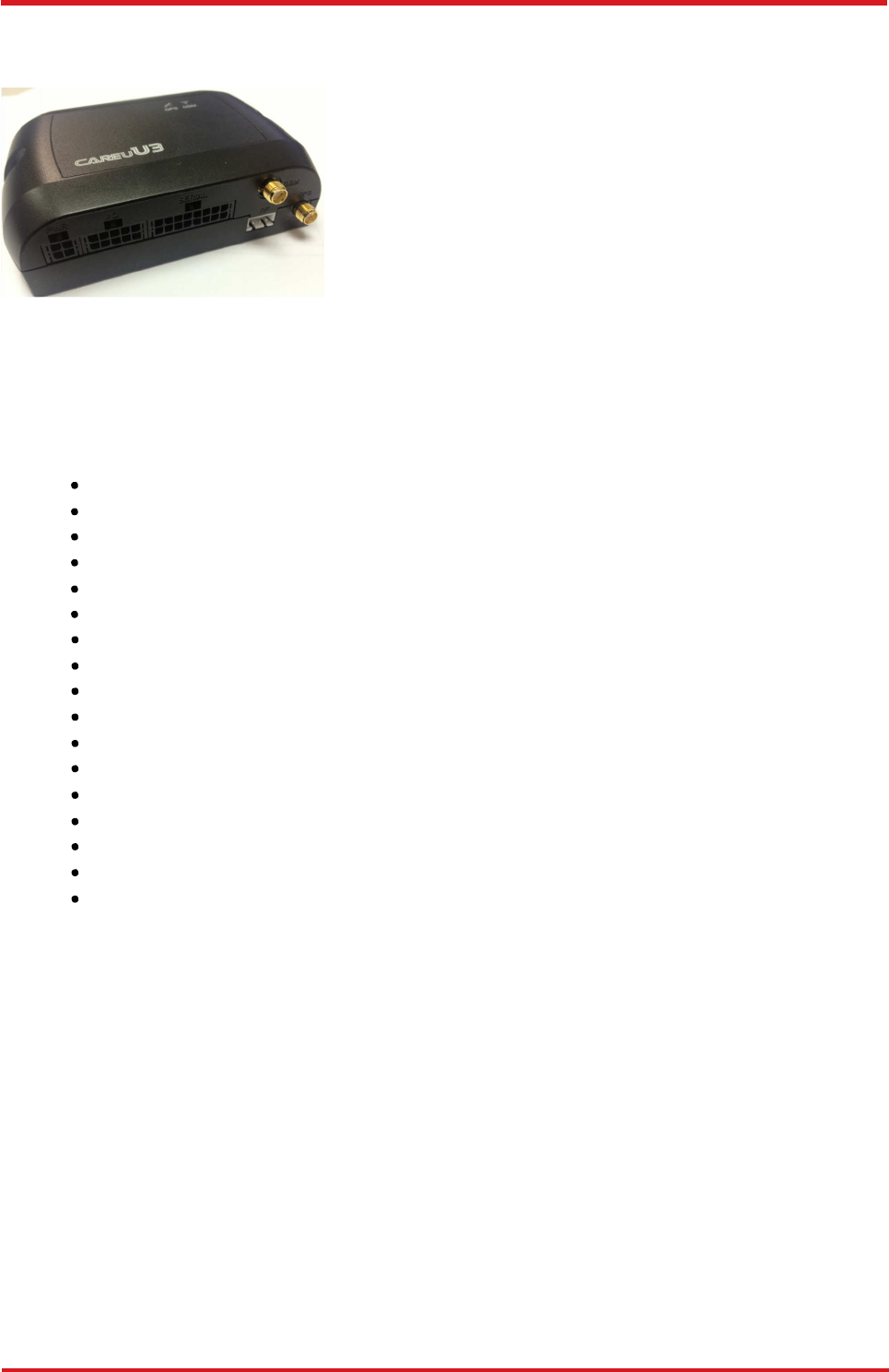
Thank you for your purchasing the CAREU U3
Vehicle Tracker. We are very pleased to introduce
you our excellent product, and you will enjoy great
benefits by applying such a smart device. The
CAREU U3 Vehicle Tracker is an all-in-one
device that integrates multiple applications of GPS
(Global Position System), GSM (Global System
for Mobile Communication) and GIS (Geographic
Information Systems) with each other.
Designed with the latest GPS technology, the CAREU U3 delivers positioning message by GSM
wireless transmission to GIS platform, and then helps back-end users proceed with the analysis
and the applications of vehicle transport, management, anti-theft, security and tracking.
1.1 Features
• Multiple serial ports and easy installation.
• Voices, FTP, SMS, GPRS TCP/UDP Communications
• Geo-fencing reports (circular/polygon/rectangle zones)
• Remote configuration
• Real-time tracking (time, distance interval or intelligent mode, and heading)
• Intelligent power management
• 1-Wire
®
interfaces supported (optional)
• Power low/lost alarm
• Built-in voice communication
• Built-in interactive voice response
• Journey report wireless download
• GSM/GPRS simultaneously
• User-defined reports
• Firmware upgrade over the air (via GPRS from FTP)
• GPS antenna disconnect/cut alarm
• Up to 150,000 data log capacity
• CAN-bus support (optional)

CAREU U
3
V
ehicle
T
racker User Guide
2
Chapter 1
1.2 Scope
This document will guides you to start the CAREU U3 Vehicle Tracker. However, as this
document contains basic device configuration only, please see the CAREU U3 Protocol
Document for the advanced information.
1.3 About CAREU U3
The CAREU U3 Vehicle Tracker transmits the wireless signals such as location, peripheral,
and vehicle control data to a control center. The onboard GPS receiver provides users with
location data including speed, direction, mileage and altitude. It uses an onboard GSM/
GPRS module to accomplish wireless transmission.
A microcontroller can probe location and command data at regular intervals, derive actions
from location, peripheral and control data, and execute such actions.
Among the best features of the CAREU U3 Vehicle Tracker, in particular, they transmit data
in ASCII mode (Intellitrac X Series compatible mode) or binary mode.
Peripheral data indicates the status of various peripherals connected to and/or controlled by
the device. The peripherals include, but not limited to, door locks/un-locks, starter interrupt,
ignition, battery, engine and panic button.
The firmware in the device applies intelligent filtering to overcome coverage limitations for
both GPS and GSM/GPRS networks.
Motion sensor controls the status of the device, whether in sleep, idle or fully-powered
mode, and thereby controls the amount of current consumed by the device.
Backup battery and tamper sensing GPS Antennas primarily indicate the loss of Main
Power and the interruption of GPS antenna connectivity.
The device supports over-the-air firmware upgrade to deliver additional functionality without
physically touching the device once installed.
In consideration of technicality and marketability, the CAREU U3 has so many excellences
to be competitive enough to stand out in the market. With regard to the technicality, the
CAREU U3 saves and records more data even under inactive communication staus, and
it also provides better power management, coexistence of GPRS and SMS modes, 1-Wire
®
interface, direct connection to Temperature Sensor, and up to three serial ports. When it
comes to the marketability, the CAREU U3 users are provided with the convenience that
its firmware can be upgraded through mini USB without disassembling the device.
CAREU U
3
V
ehicle
T
racker User Guide
Chapter 1
3
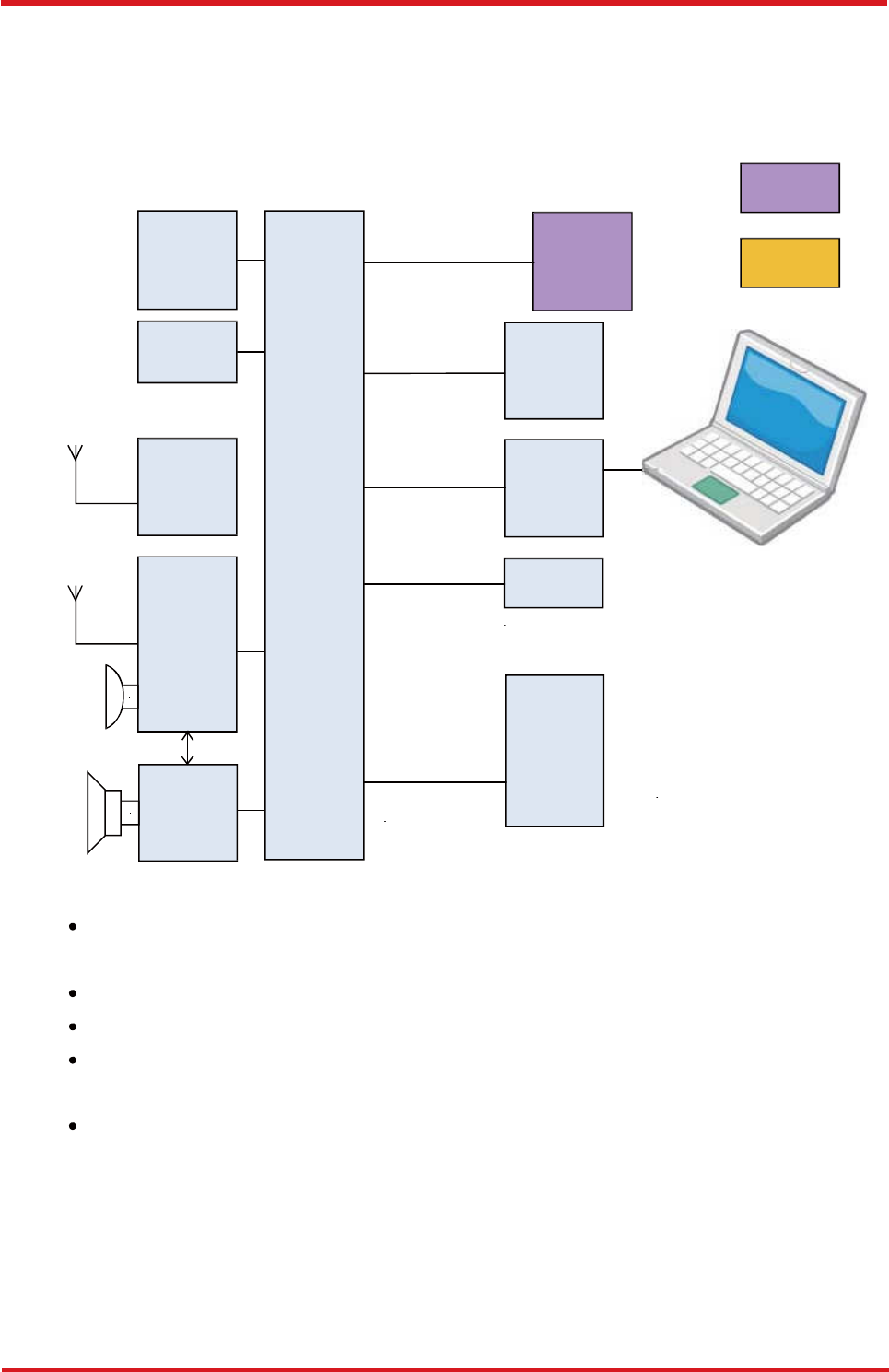
1.4 Hardware Architecture
As hardware is concerned, the CAREU U3 is comprised of a micro-controller, regulator,
GPS receiver, GSM/GPRS modem, G-Force sensor, flash memory data storage,
audio interface, I/Os interface, serial ports and LED status indicators.
Optional
SPI
FLASH
CAN
External
Device
G-Sensor
I/O Ports
GPS USB
CPU
Power
MIC
Speaker
GSM
Modem
Audio
Audio
AMP
RS232
• Users can connect PC's HyperTerminal to the Diagnostic/setting port for the AVL
configuration.
• G-Sensor for car accident prevention, car tow-away warning and power management.
• The audio interface supports hand-free phone call.
• GPIO that connects to any customer monitoring points by door switch, anti-thief or
actuators.
• The A/D input that connects the analog signal sensor to the AVL, such as the fuel or
temperature sensor.

CAREU U
3
V
ehicle
T
racker User Guide
4
Chapter 1
1.5 Related Document
[1] CAREU U3 Protocol Document
CAREU U
3
V
ehicle
T
racker User Guide
Chapter 2
5
31.10
72.00
Chapter 2. Taking a Tour of CAREU U3
This chapter will guide you to the major connectors of the U3 device.
2.1 Dimensions
108.00
Dimensions: 108mm x 72mm x 31mm
CAREU U
3
V
ehicle
T
racker User Guide
Chapter 2
6
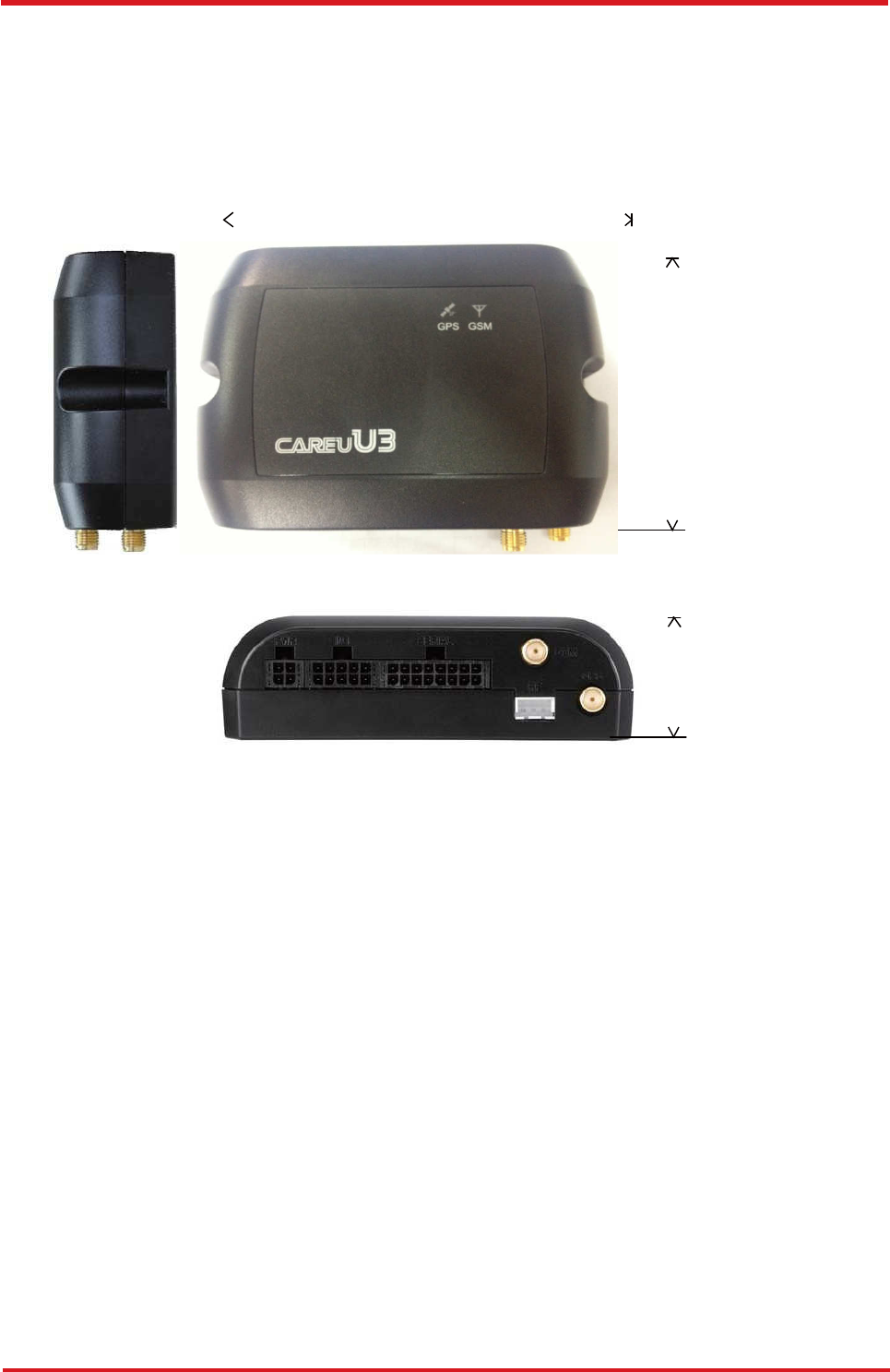
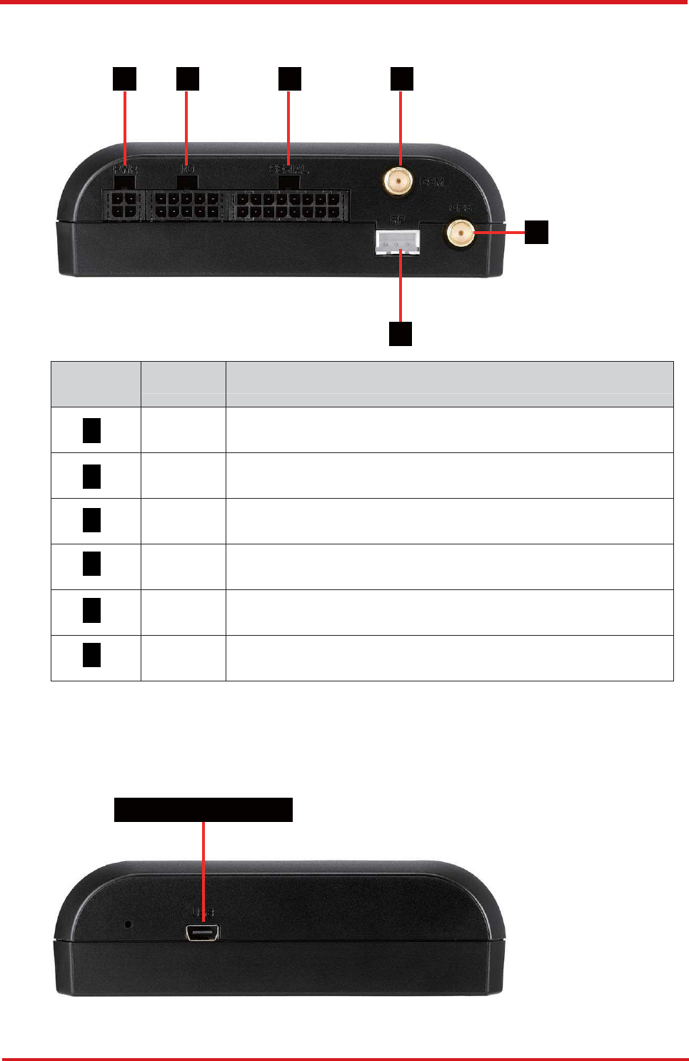
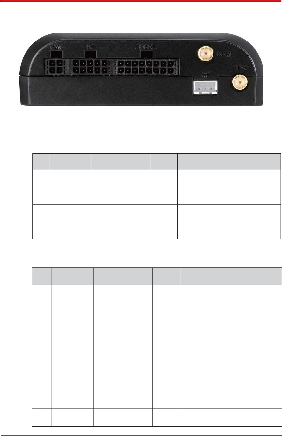
2.2 Front View
1 2 3 4
6
5
No.
Name
Description
1
PWR
Power Connector for Car Battery
2
I/O
Input/Output Connector including basic I/O, RS-232
3
SERIAL
Serial Connector
4
GSM
SMA Connector for GSM External Receiver
5
6
GPS
SMA Connector for GPS External Antenna
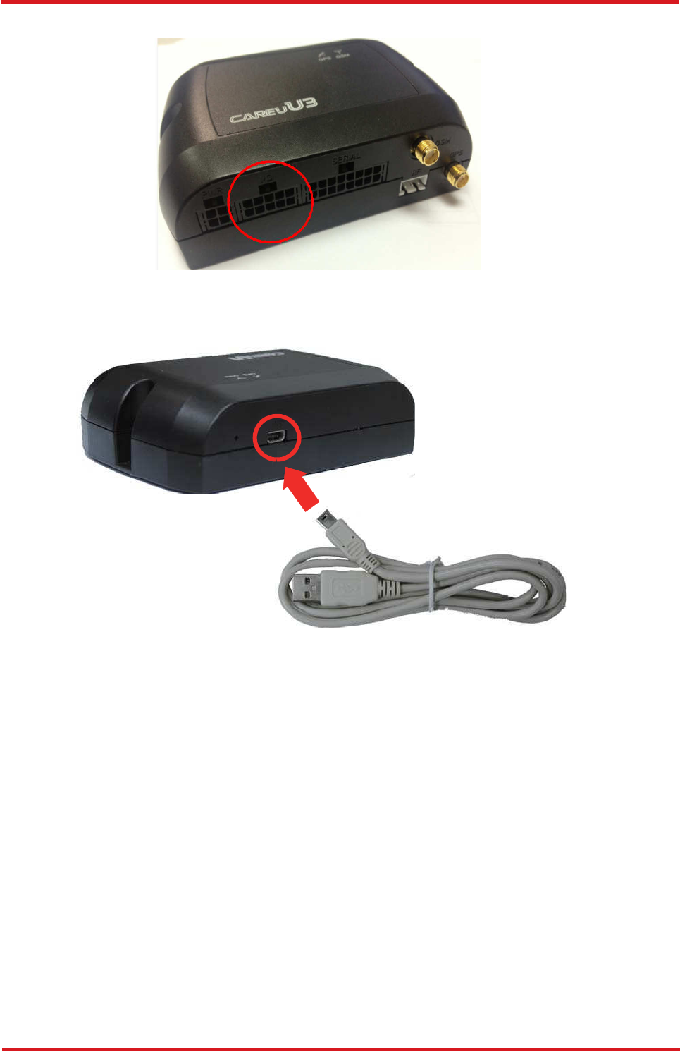
2.3 Rear View
Mini USB Connector
CAREU U
3
V
ehicle
T
racker User Guide
Chapter 3
7
Chapter 3. Getting Started with CAREU U3
To install the the CAREU U3 device, follow the instructions below for basic operations.
3.1 Hardware Installation
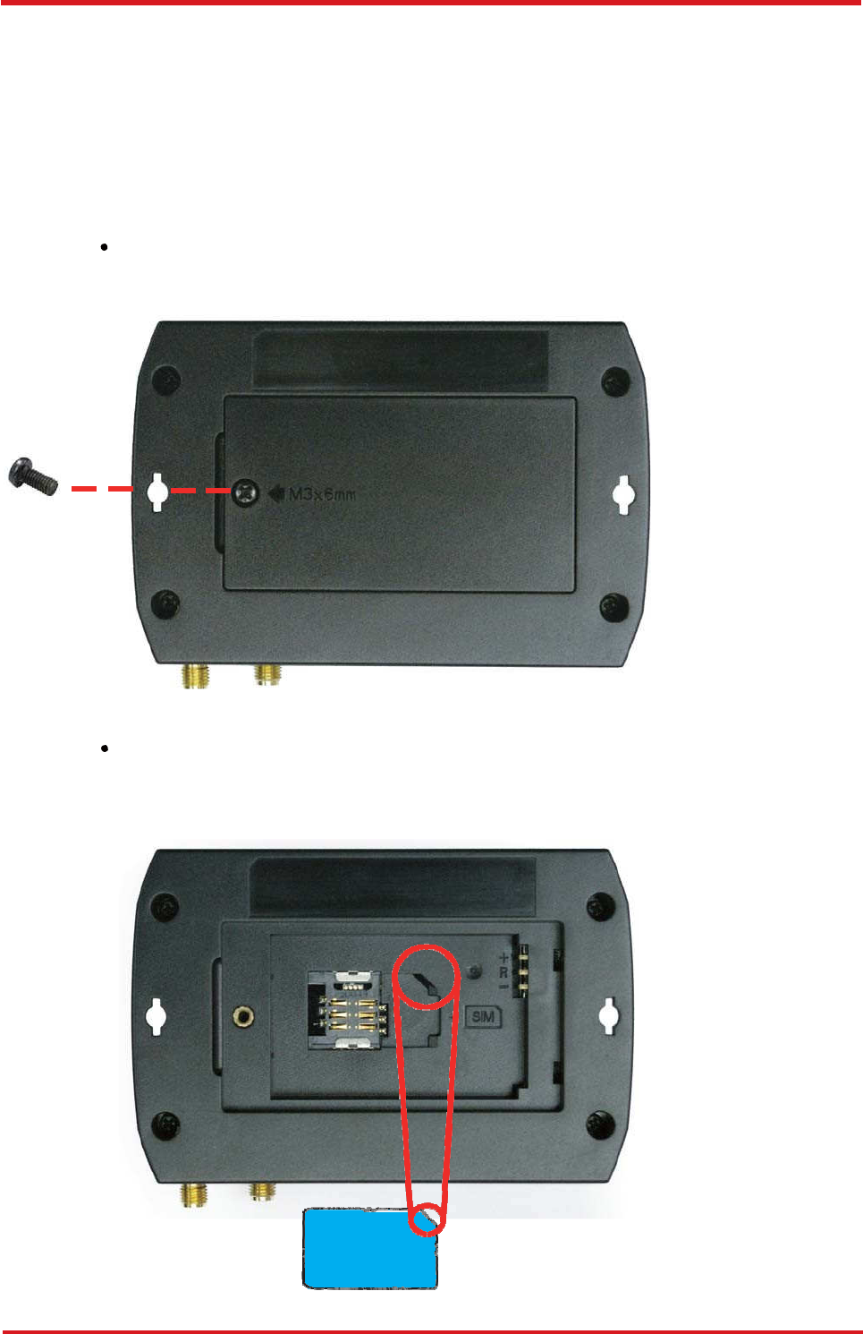
1. SIM Card Installation
• Remove the screw at the bottom of the device to open it. Then you will find the SIM
card slot inside.
• Insert your SIM card into the device with SIM card's gold area down and the
notched corner toward the notched edge of the SIM card socket. Make sure it is
installed correctly in place. Reinstall the cover.
SIM Card
CAREU U
3
V
ehicle
T
racker User Guide
8
Chapter 3
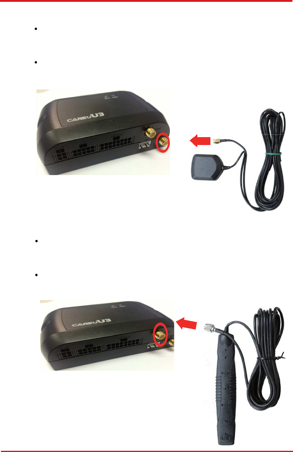
2. GPS Antenna Connection
• Connect the GPS antenna to the SMA connector jack on the front side of the device
(circled as the illustration below) by completely screwing the GPS antenna's plug
connector.
• It is recommended that a matching torque 7-10 inch pounds (80-110 N.cm) should
be used for the SMA connector.
3. GSM Antenna Connection
• Connect the GSM antenna to the SMA connector jack on the front side of the device
(circled) as illustration below) by completely screwing the GSM antenna's plug
connector.
• It is recommended that a matching torque 7-10 inch pounds (80-110 N.cm) should
be used for the SMA connector.
CAREU U
3
V
ehicle
T
racker User Guide
Chapter 3
9
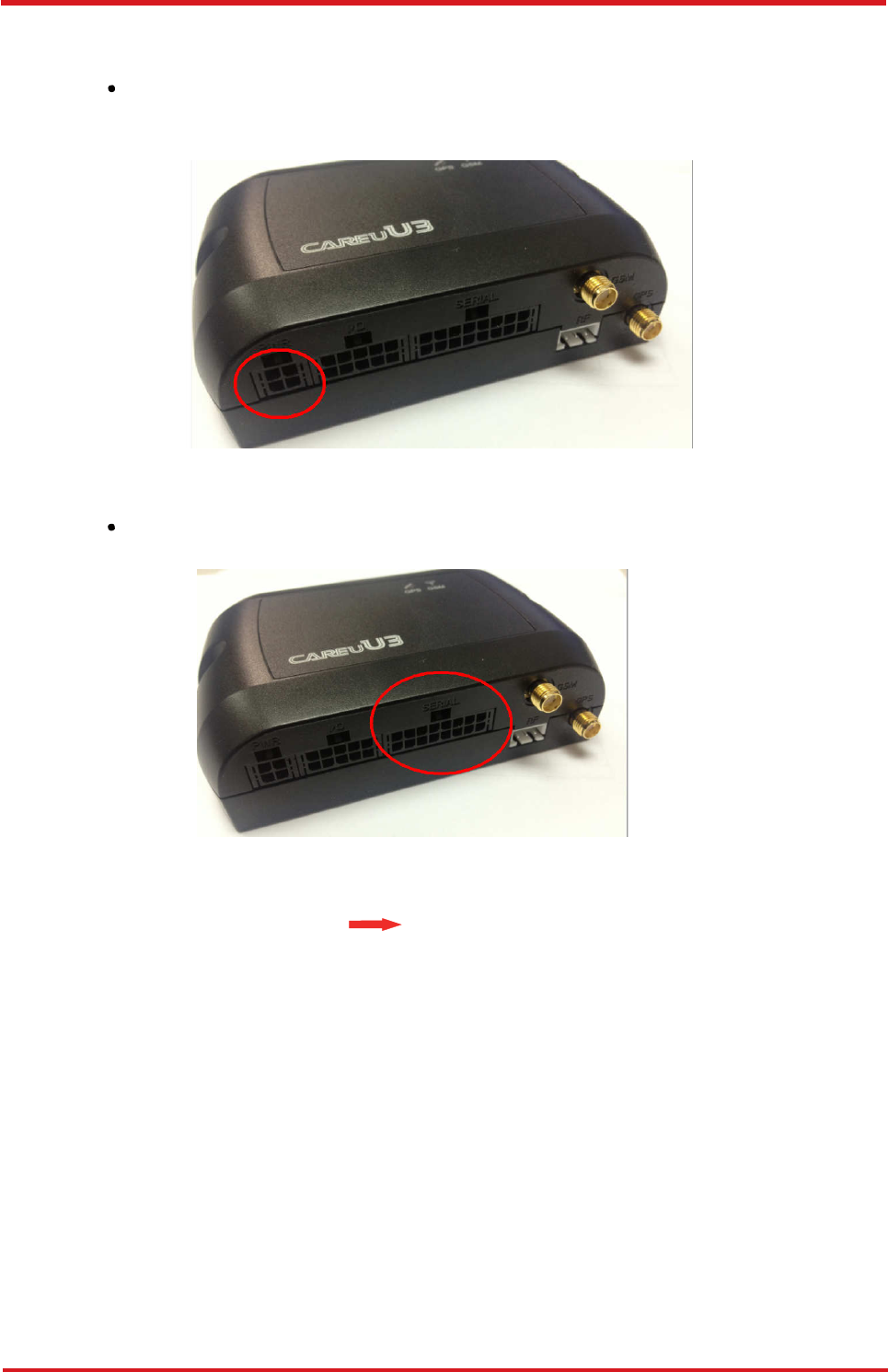
4. Power, RS-232, and I/O Cable Connection
• Connect 4-wire power cable to the power connector on the front side of the
CAREU U3 device (8~30V)
• Connect the 8-wire cable to the CARE U3 device which enables the connection of
the CARE U3 to your system and also to related peripherals.
Only these 4 pins
are to connect to
your PC.

CAREU U
3
V
ehicle
T
racker User Guide
10
Chapter 3
• Good Wiring Installation
Please reserve approximately 1 cm accommodation before folding the cable.
Folding cable directly on connector may result in poor contact on connector pin
Correct way of folding cable
1cm 1cm
Incorrect way of folding cable
CAREU U
3
V
ehicle
T
racker User Guide
Chapter 3
11
5. I/O Cable Connection
6. Mini USB Cable Connection
7. G-Sensor Installation Consideration
The device uses a 3-axis G-Force sensor to detect the vehicle motion and the impact
on the vehicle. The X, Y and Z axis definition will be affected by the location of device
installation.
CAREU U
3
V
ehicle
T
racker User Guide
12
Chapter 3
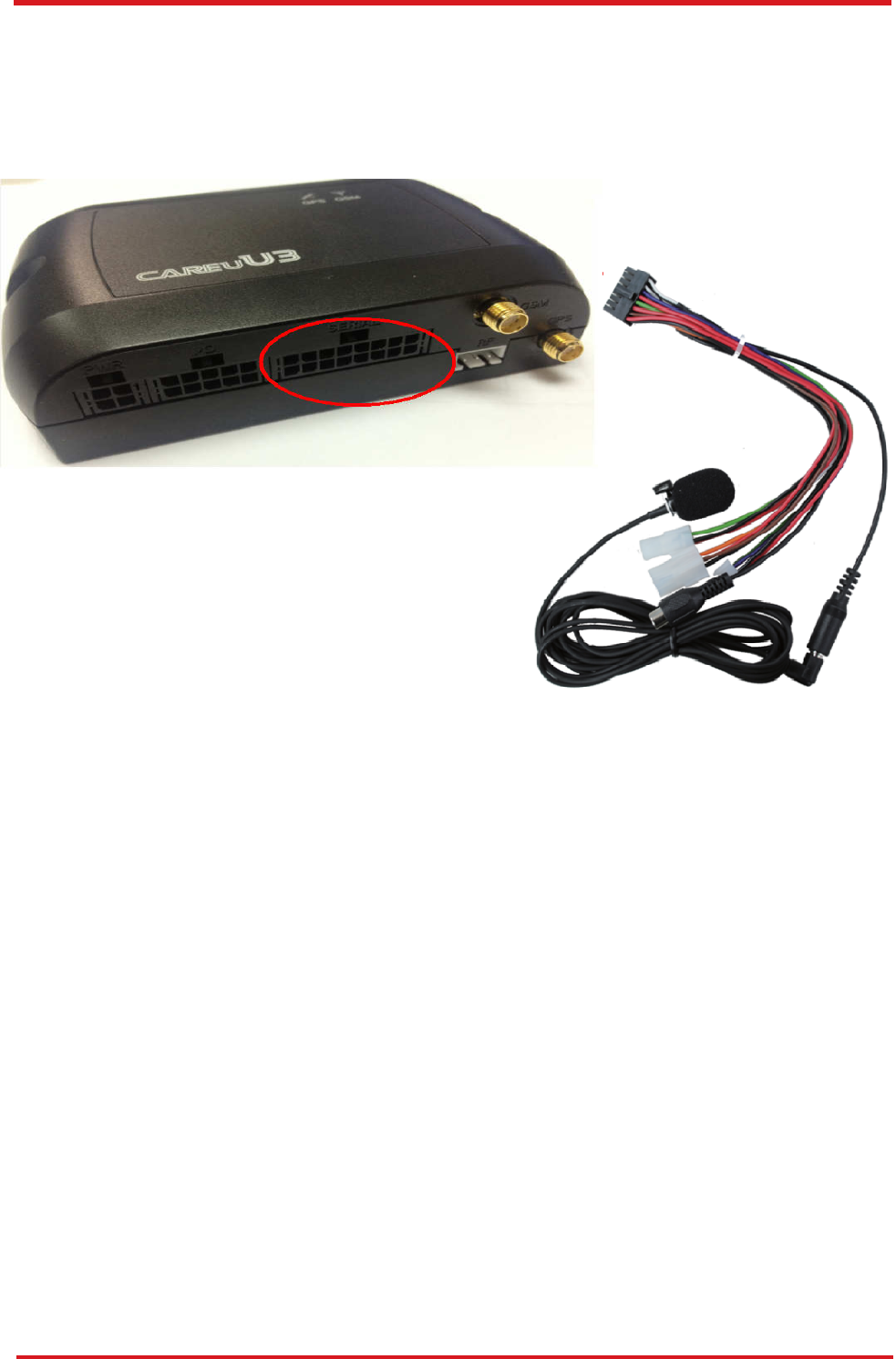
8. Microphone Installation (Optional)
Connect the microphone set to the 8-wire cables first. Plug the connector of the 8-wire
cable completely into to the seial port on the front side of the device. See the
illustration below.
9. Speaker Installation (Optional)
Connect the speaker set to the 8-wire cables first. Plug the connector of the 8-wire
cable completely into to the seial port on the front side of the device. See the
illustration below.
CAREU U
3
V
ehicle
T
racker User Guide
Chapter 3
13
1 3
1 3
5
7 9
1 3 5 7 9 11 13 15
2 4
2 4
6
8 10
2 4 6 8 101214 16
3.2 Connector Pin Assignment
Connector Pin Definition
1. PWR Connector
Pin#
Signal Name
Description
I/O
Remark
1
DC IN
Power supply input
I
DC Vin = +8 ~ +30V
Normal = 70mA @ 12V
2
GND
Signal ground
----
3
Ignition
Ignition(ACC) Input
I
DC Vin = +30 ~ +7V (Active high)
4
Output1
Open-Collector
Output1
O
Imax = 300mA
2. I/O Connector
Pin#
Signal Name
Description
I/O
Remark
Analog Input
2
Analog Input 2
I
DC VIN = +30V ~ 0V (default)
1
Input 3
(Optional)
Positive Trigger
input 3
I
DC VIN = +30V ~ +7V (High
Active)
2
Input 4
Positive Trigger
input 4
I
DC VIN = +30V ~ +7V (High
Active)
3
Input 1
Negative Trigger
input 1
I
DC VIN = +6V ~ 0V (Low Active)
4
Input 2
Negative Trigger
input 2
I
DC VIN = +6V ~ 0V (Low Active)
5
Analog Input
1
Analog input 1
I
DC VIN = +30V ~ 0V
6
GND
Signal ground
----
7
Output 2
Open-Collector
Output 2
O
Imax = 300mA

CAREU U
3
V
ehicle
T
racker User Guide
14
Chapter 3
Pin#
Signal Name
Description
I/O
Remark
8
Output 3
Open-Collector
Output 3
O
Imax = 300mA
9
CAN H
CAN High
I
VI = 2.75V ~ 4.5V
10
CAN L
CAN Low
I
VI = 0.5V ~ 2.25V
3. Serial Connector
Pin#
Signal Name
Description
IO
Remark
1
Vout1
Supply voltage output
O
Vo = 5V ( Vout 1~3 Total Imax =
500mA )
2
GND
Signal ground
-
3
TX1
RS-232 Data output
O
4
RX1
RS-232 Data input
I
Support Accessories:
Garmin FMI PND, MDT M1/M7/
M7+
5
Vout2
Supply voltage output
O
6
GND
Signal ground
-
Vo = 5.0V, (Vout1~3 Total Imax
= 500mA)
7
TX2
RS-232 Data output
O
8
RX2
RS-232 Data input
I
Support
Audio Box,
Supply voltage output
The Vout3 is not available on the
1-Wired Version
9
Vout2
1-Wire
®
1-Wire
®
Data input
O
I
It is only available on the 1-Wired
Version
10
GND
1-Wire
®
_
GND
Signal ground
1-Wire
®
ground
-
-
(Optional)
11
TX3
RS-232 Data output
O
12
RX3
RS-232 Data input
I
13
SPK+
Audio output
O
14
SPK-
Audio output
O
15
MIC+
Microphone Input
I
16
MIC-
Microphone Input
I

CAREU U
3
V
ehicle
T
racker User Guide
Chapter 3
15
3.3 LED Indicator
1. GPS LED Indicator
Power Mode
GPS Status
GPS LED
Power Off
N/A
Off
Low Power
N/A
Off
Full Power
Acquiring
Flash Red (five times/second)
Full Power
Tracking
Solid Red
2. GSM LED Indicator
Power Mode
GSM/GPRS Status
GSM LED
Power Off
N/A
Off
Low Power
N/A
Off
Full Power
Acquiring
Flash Red (three times/
second)
Full Power
Registered
Solid Red
CAREU U
3
V
ehicle
T
racker User Guide
16
Chapter 3
3.4 USB Device Driver Installation
The CAREU U3 communicates with your host computer by either RS-232 or USB
interface.
In some newer editions of Windows XP, the CAREU U3 device can be installed as a "virtual
COM port" device whereby the CAREU U3 would automatically access Windows XP's
inbox USB drivers. While in some other earlier editions of Windows XP, you would need to
manually install the USB driver for the CAREU U3 device. In the following content of this
section, you will be guided to how the installation can be done in both cases.
To install the device driver for the CAREU U3, connect the CAREU U3 device to your
system with an USB cable as mentioned in Mini USB Cable Connection on page 11.
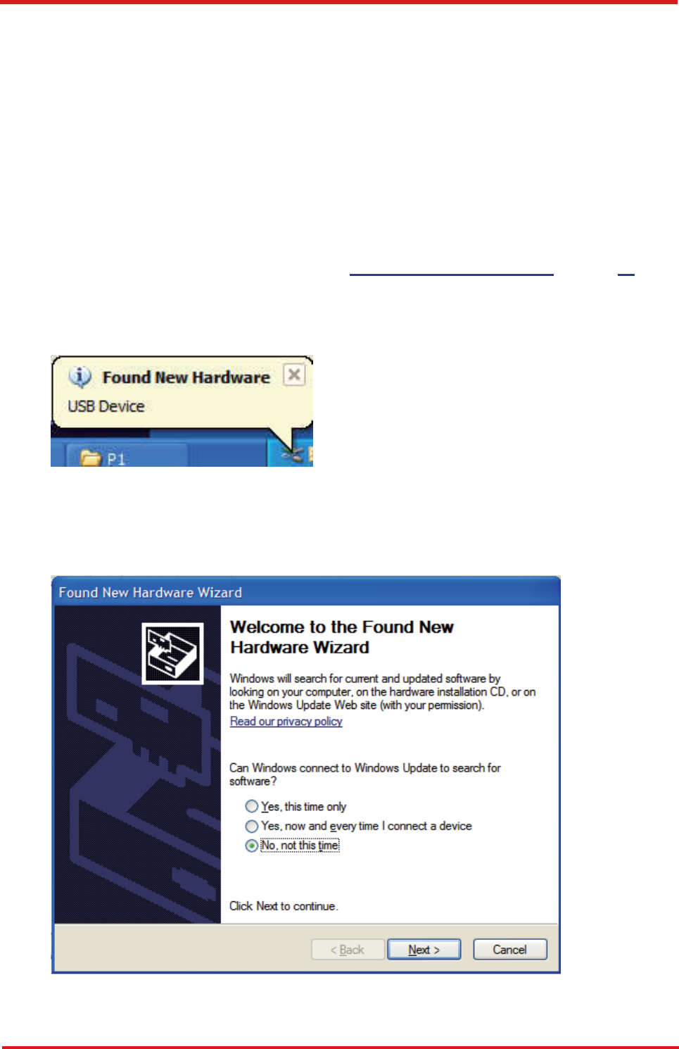
As soon as the connection is made between the CAREU U3 and your computer, a balloon
appears above the notification area saying an USB device is found.
Click on this balloon to start the [Found New Hardware] wizard.
Select No, not this time. Press the Next button to proceed.
CAREU U
3
V
ehicle
T
racker User Guide
Chapter 3
17
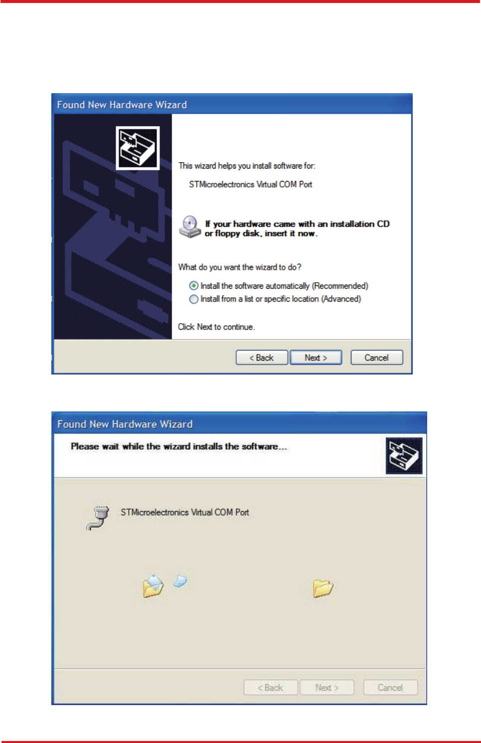
1. Automatic Installation
If the wizard prompts to help you install the software for "STMicroelectronics Virtual
COM Port". Select Install the software automatically (Recommended). Press the
Next button to proceed.
The wizard proceeds to install the driver.
CAREU U
3
V
ehicle
T
racker User Guide
18
Chapter 3
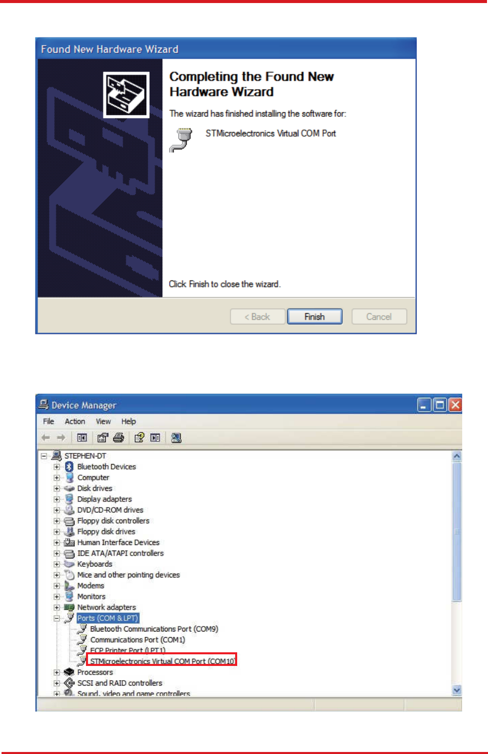
The installation completes.
In [Device Manager], the CAREU U3 device is included under Ports (COM & LPT) as
"STMicroelectronics Virtual COM Port". COM port number is displayed as well.
CAREU U
3
V
ehicle
T
racker User Guide
Chapter 3
19
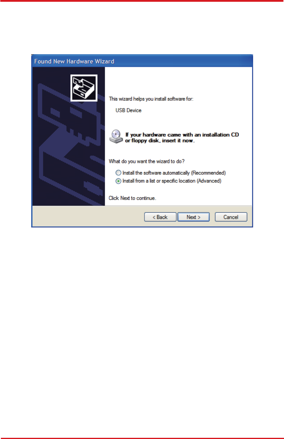
2. Manual Installation
After you select No, not this time, if the wizard only prompts to help you install software
for "USB device", you need to manually install the driver. Select Install from a list or
specific location (Advanced). Press the the Next button to proceed.
CAREU U
3
V
ehicle
T
racker User Guide
20
Chapter 3
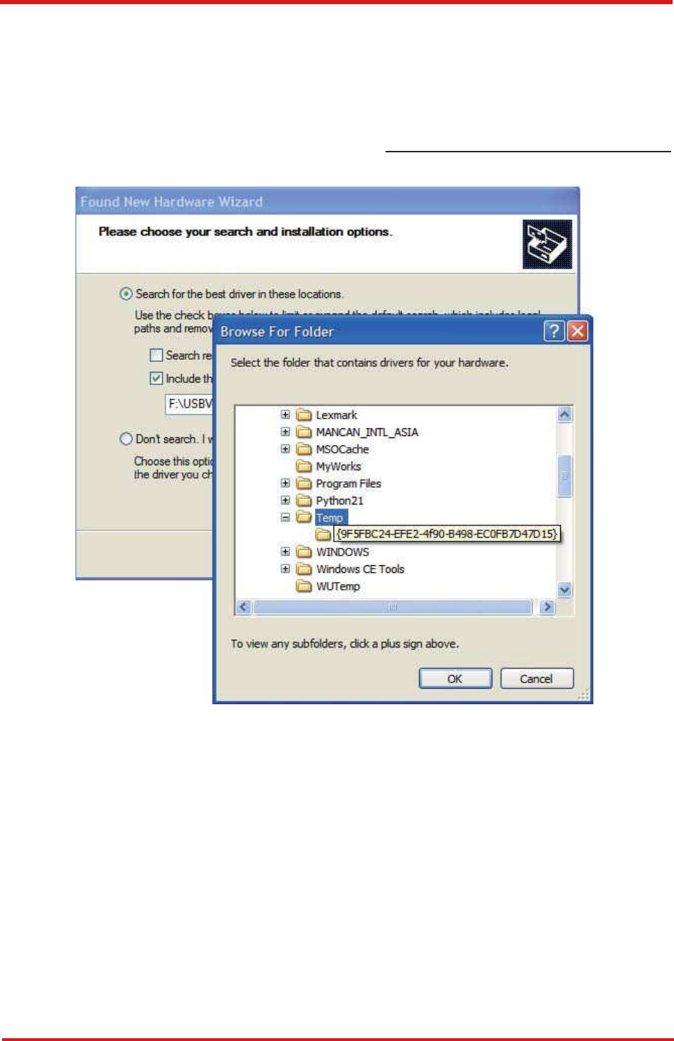
Select Search for the best driver in these locations. Check Include this location
in the search. Press the Browse button to assign where your the CAREU U3 device
driver locates on your local disk.
Press the OK button.
You can download the USB device driver from http://www.systech.com.tw/downloads.php.
CAREU U
3
V
ehicle
T
racker User Guide
Chapter 3
21
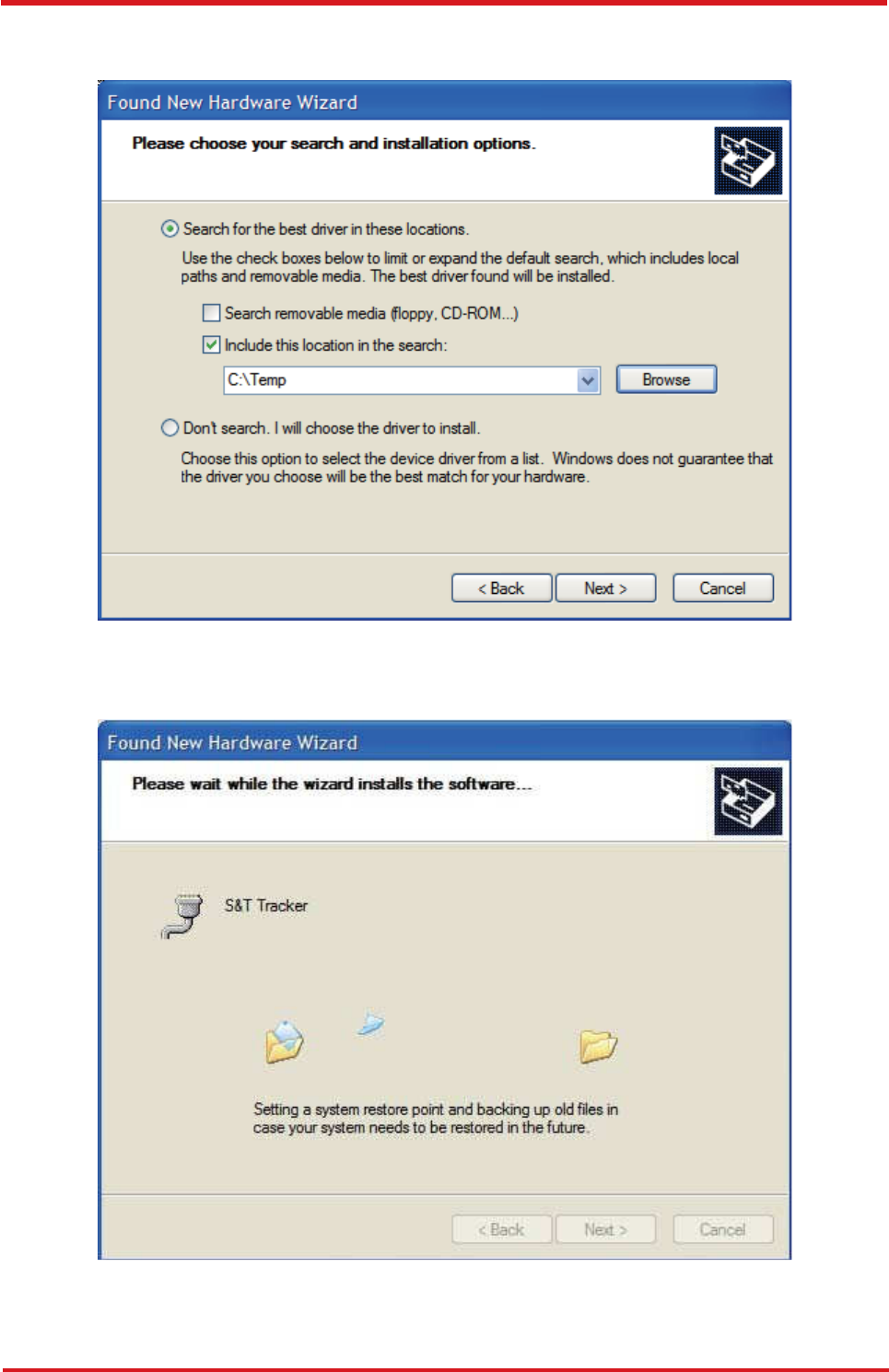
Press the Next button to proceed.
The wizard proceeds to install the driver.
CAREU U
3
V
ehicle
T
racker User Guide
22
Chapter 3
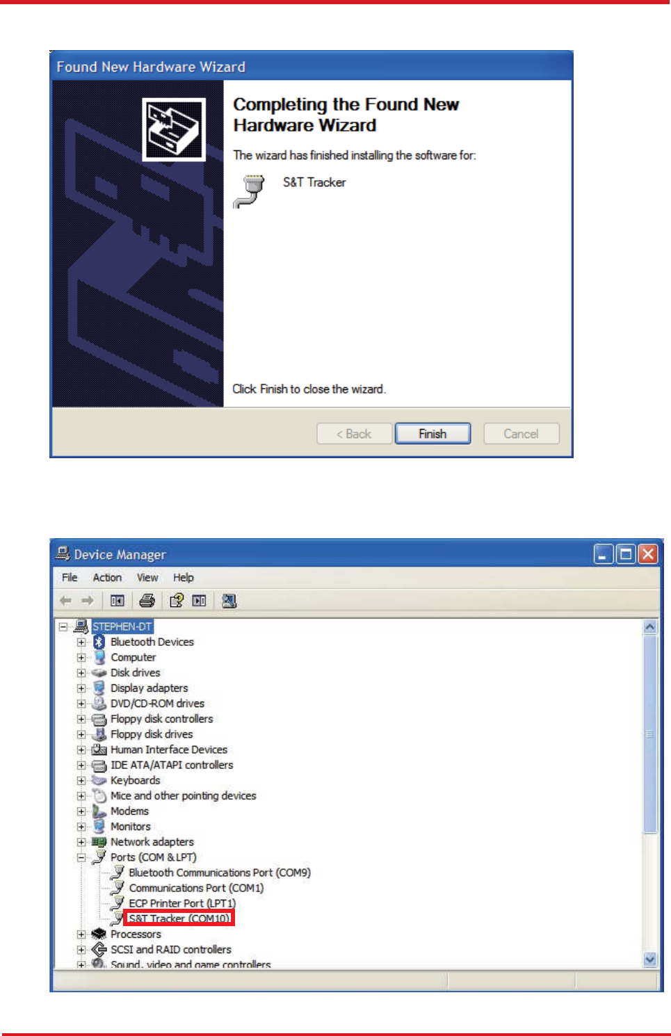
The installation completes.
In [Device Manager], the CAREU U3 device is included under Ports (COM & LPT) as
"S&T Tracker". COM port number is displayed as well.
CAREU U
3
V
ehicle
T
racker User Guide
Chapter 3
23
3.5 Device Configuration
1. In Windows XP desktop, click Start | All Programs | Accessories |
Communications | HyperTerminal.
2. If you are prompted to input the information of your location, complete them to proceed.
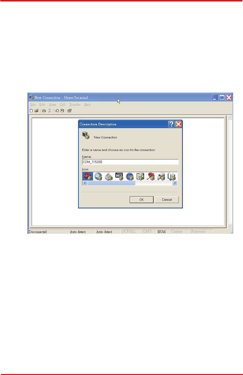
3. On the File menu of HyperTerminal, click New Connection.
4. In the Name box, type a name that describes the connection. In the Icon box, click
an appropriate icon. Press the OK button to proceed.
5. For Com port properties, configure as follows:
Baud Rate --> 115200 bps
Data Bits --> 8
Parity --> None
Stop Bits --> 1
Flow Control --> None
CAREU U
3
V
ehicle
T
racker User Guide
24
Chapter 3
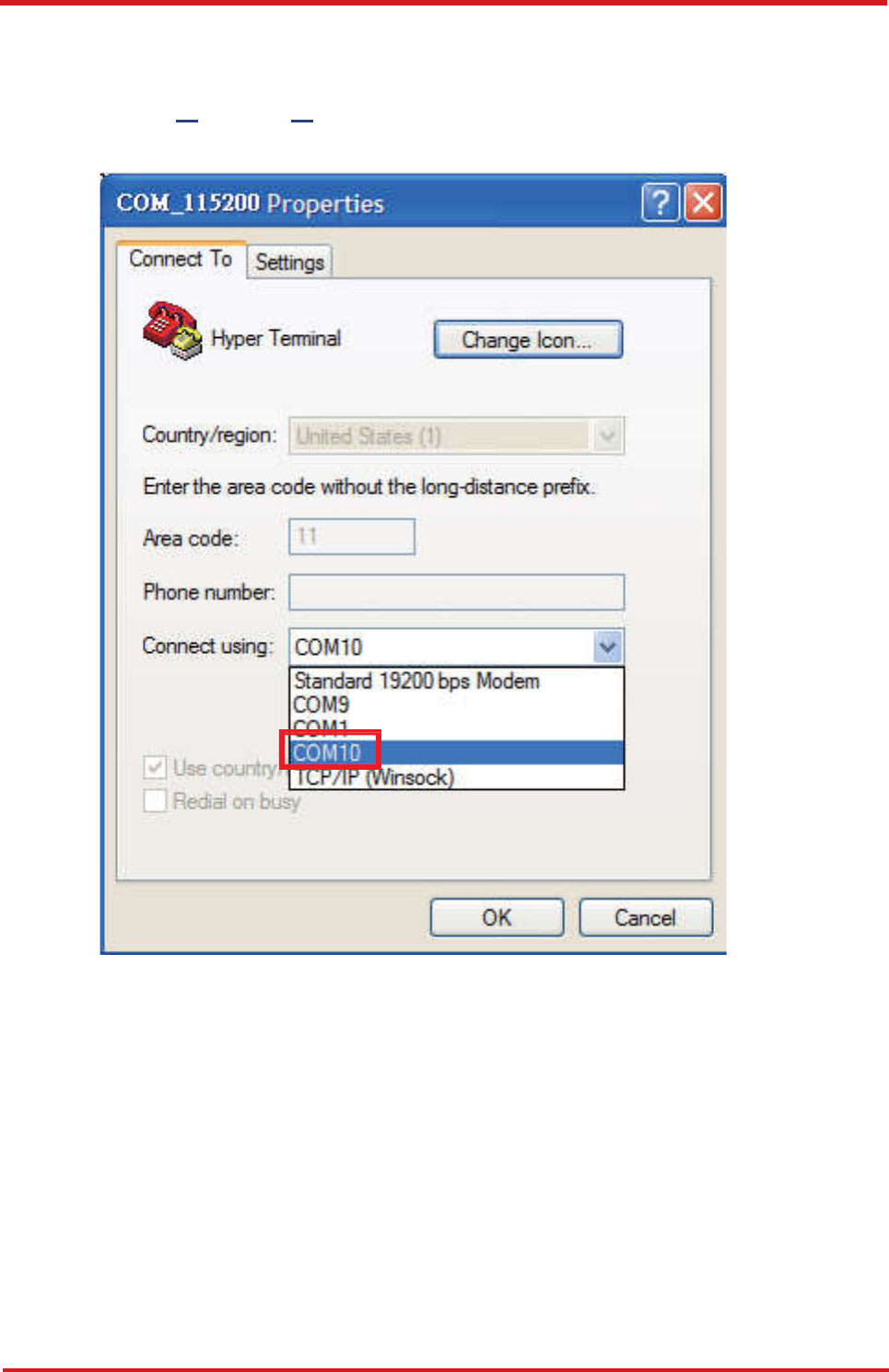
6. In the connection that you have just set up, click File | Properties. Select the
[Connect To] tab. From the [Connect using] drop down list, select the correct com
port by checking it up at Windows XP's [DeviceManager] as previously mentioned
on page 29 and page 33. Go there by clicking Start | Control Panel | System | Hardware |
Device Manager.
CAREU U
3
V
ehicle
T
racker User Guide
Chapter 3
25
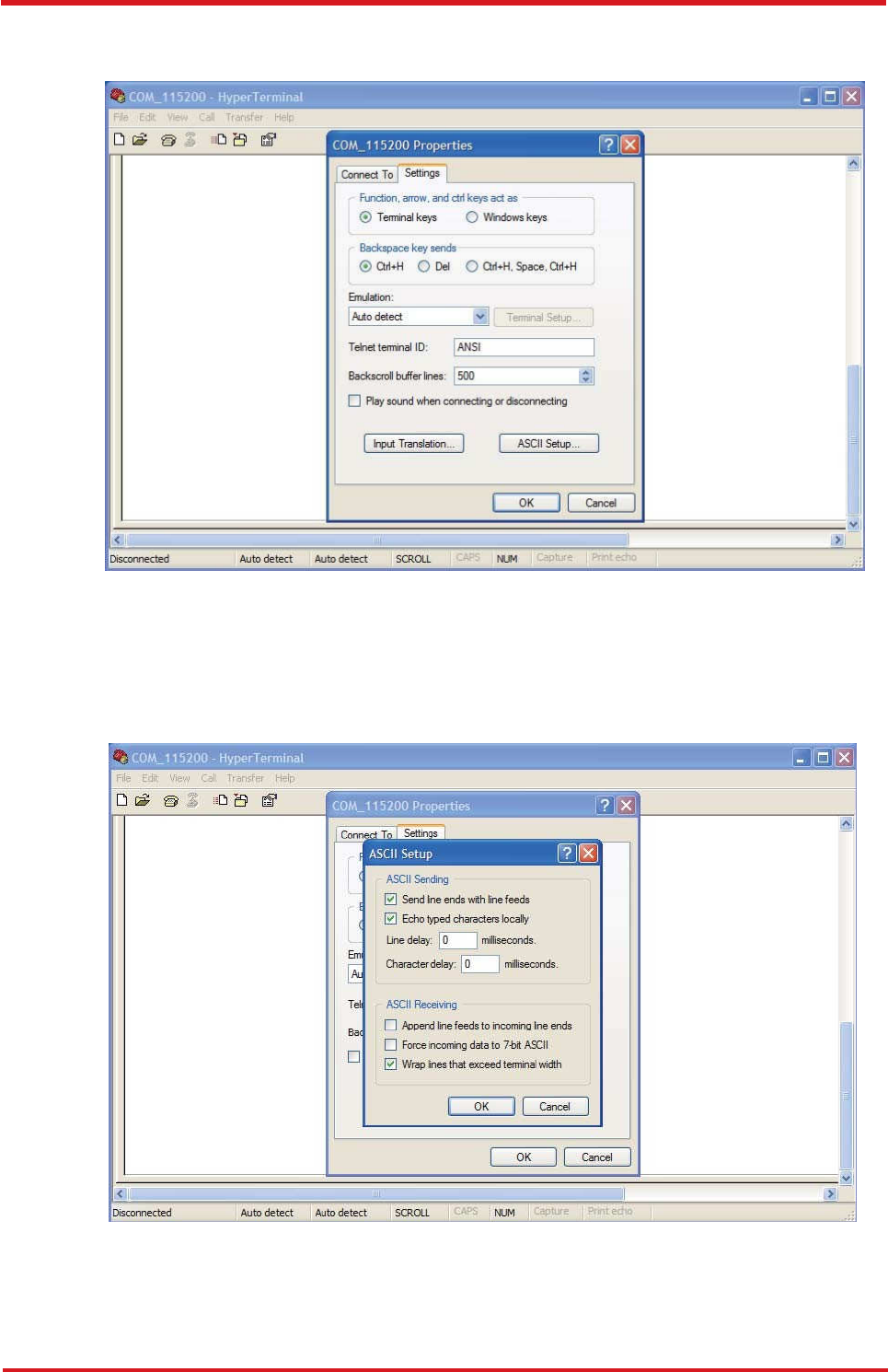
7. In the File menu, click Properties. Click the [Settings] tab. Press the ASCII Setup
button.
8. In the [ASCII Sending] group box. Select both Send line ends with line feeds and
Echo typed characters locally. Press the OK button.
CAREU U
3
V
ehicle
T
racker User Guide
26
Chapter 3
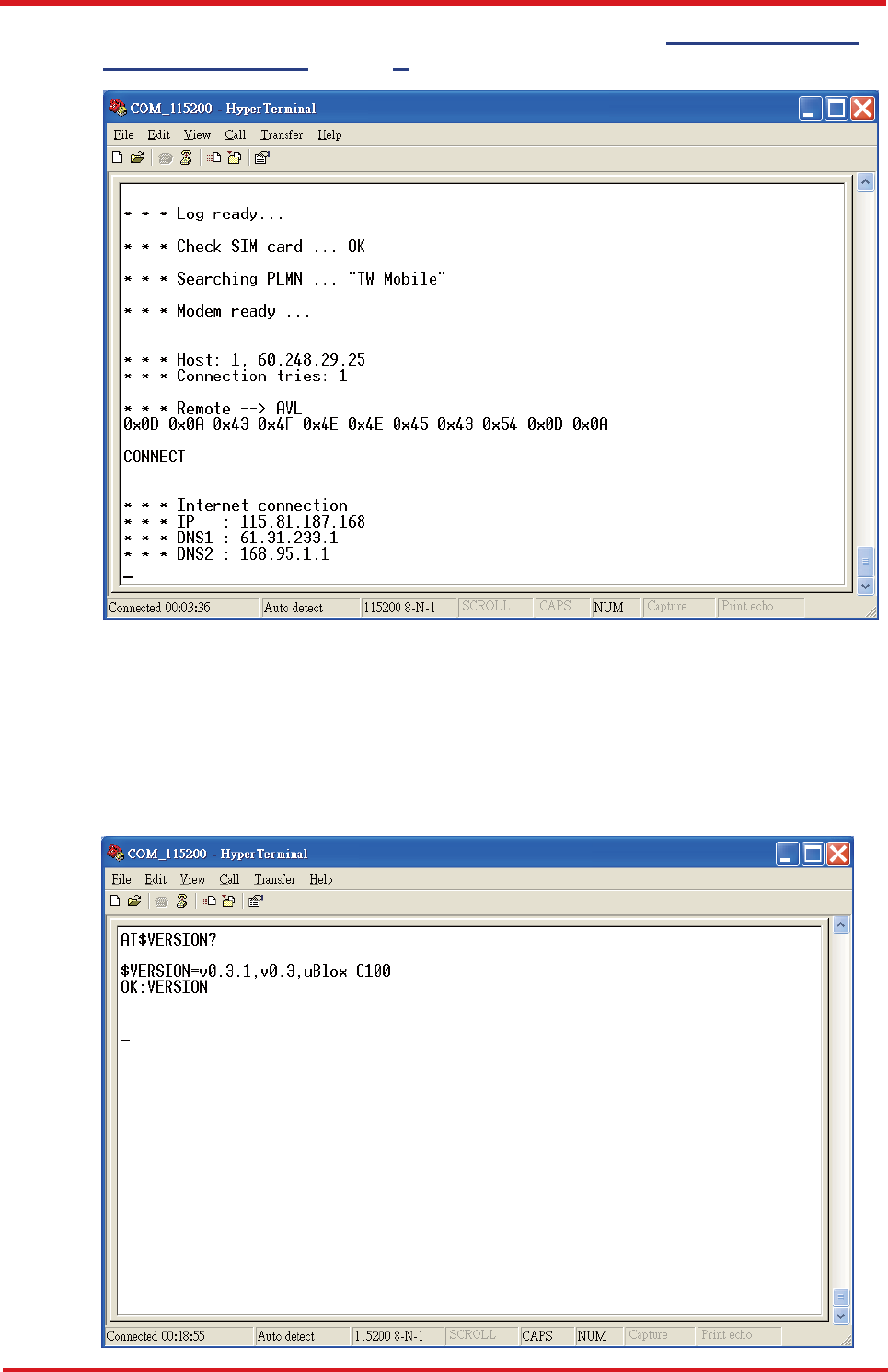
9. Connect your the CAREU U3 device to power as mentioned in Power, RS-232, and
I/O Cable Connection on page 9. The device startup message will be displayed.
10. In [HyperTerminal] window, type in the command "AT$VERSION?" and press the
Enter key. The hardware and firmware version will show. As long as your
[HyperTerminal] window appears as the screenshot below, a connection between the
device and your system has already been built up and working. It is time to send all
configuration commands.

CAREU U
3
V
ehicle
T
racker User Guide
Chapter 3
27
3.6 Communication Settings
The CAREU U3 Vehicle Tracker communicates with your control center by either SMS or
GPRS (TCP/UDP). Before the device is installed into a vehicle, communication
parameters should be set.
1. SMS Configuration
Use AT$SMSDST command to set a SMS control center phone number or short code.
For example, if the SMS control center phone number is +886123456789, the
AT$SMSDST command to be issued into HyperTerminal should be:
AT$SMSDST=+886123456789
OK
Then you can try to use cellular phone or SMS gateway to send a SMS message to
the CAREU U3 device. Send a SMS message --> "AT$MODID?"
Device will response:
$MODID=101000001
OK
This proves a successful mobile phone SMS connection.

CAREU U
3
V
ehicle
T
racker User Guide
28
Chapter 3
2. GPRS Configuration
Set GPRS servers by using the folloiwng commands:
AT$APN=internet,username,password (APN=internet, Username=username,
Password=password) OK
AT$HOSTS=1,0,60.148.19.10,6000
(Server IP address = 60.148.19.10 and Port number =6000)
OK
AT$RETRY=5,10 (Message retry settings)
OK
AT$IPTYPE=1 (Using TCP/IP mode)
OK
AT$GPRSEN=1 (GPRS enable)
OK
AT$HB=60,1 (Heartbeat setting)
OK
Please refer to the CAREU U3 Protocol Document for more command details.
CAREU U
3
V
ehicle
T
racker User Guide
Chapter 3
29
3.7 GPS Tracking Configurations
After the device communication settings are done, the remote GPS tracking is ready to
function. The setting of GPS tracking can be done by using AT$PDSR command. For
example,
AT$PDSR=1,30,0,0,2,0,0,1,1 (Tracking through GPRS by time interval 30 seconds)
OK
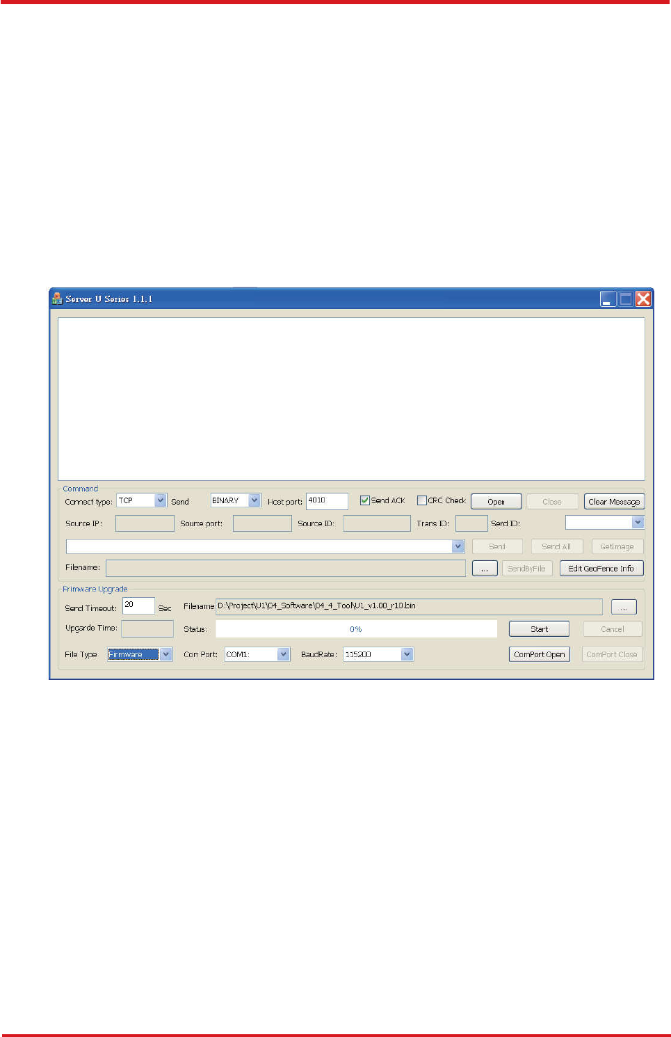
For simple testing GPRS, run the TCP Server U-Series software which is provided by
S&T. It is simple server software that can wait for device connection and data.
CAREU U
3
V
ehicle
T
racker User Guide
30
Chapter 3
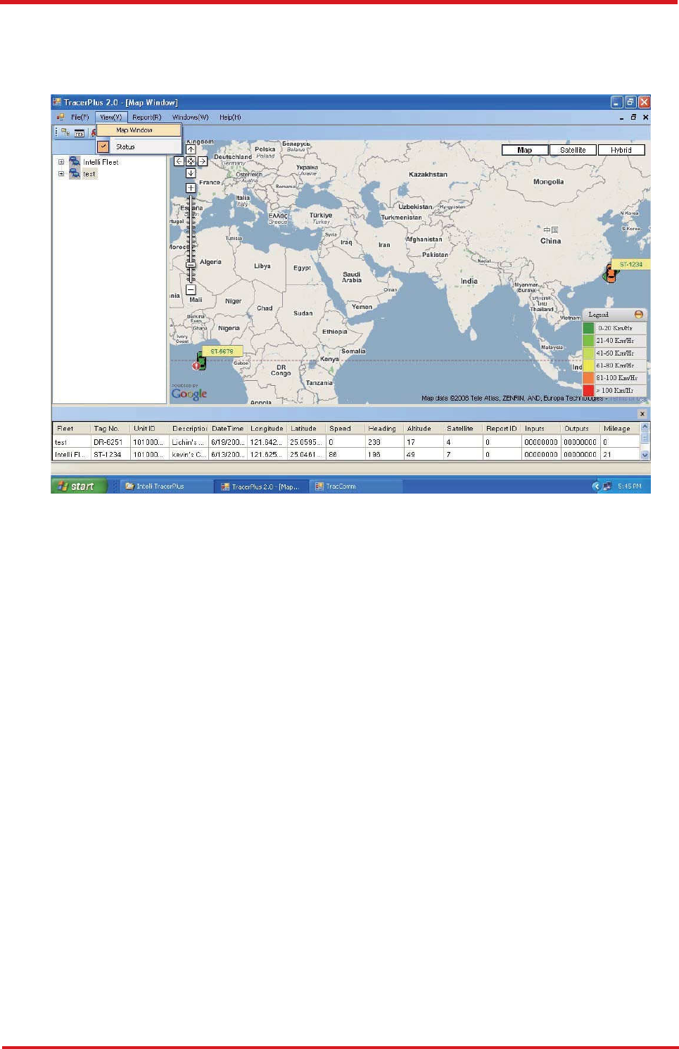
For advanced testing, you need the software Intelli TracerPlus. Please
request this software through your sales contact.
You can also apply for a testing account from S&T's FleetWeb solution through your sales
contact.
CAREU U
3
V
ehicle
T
racker User Guide
Chapter 3
31
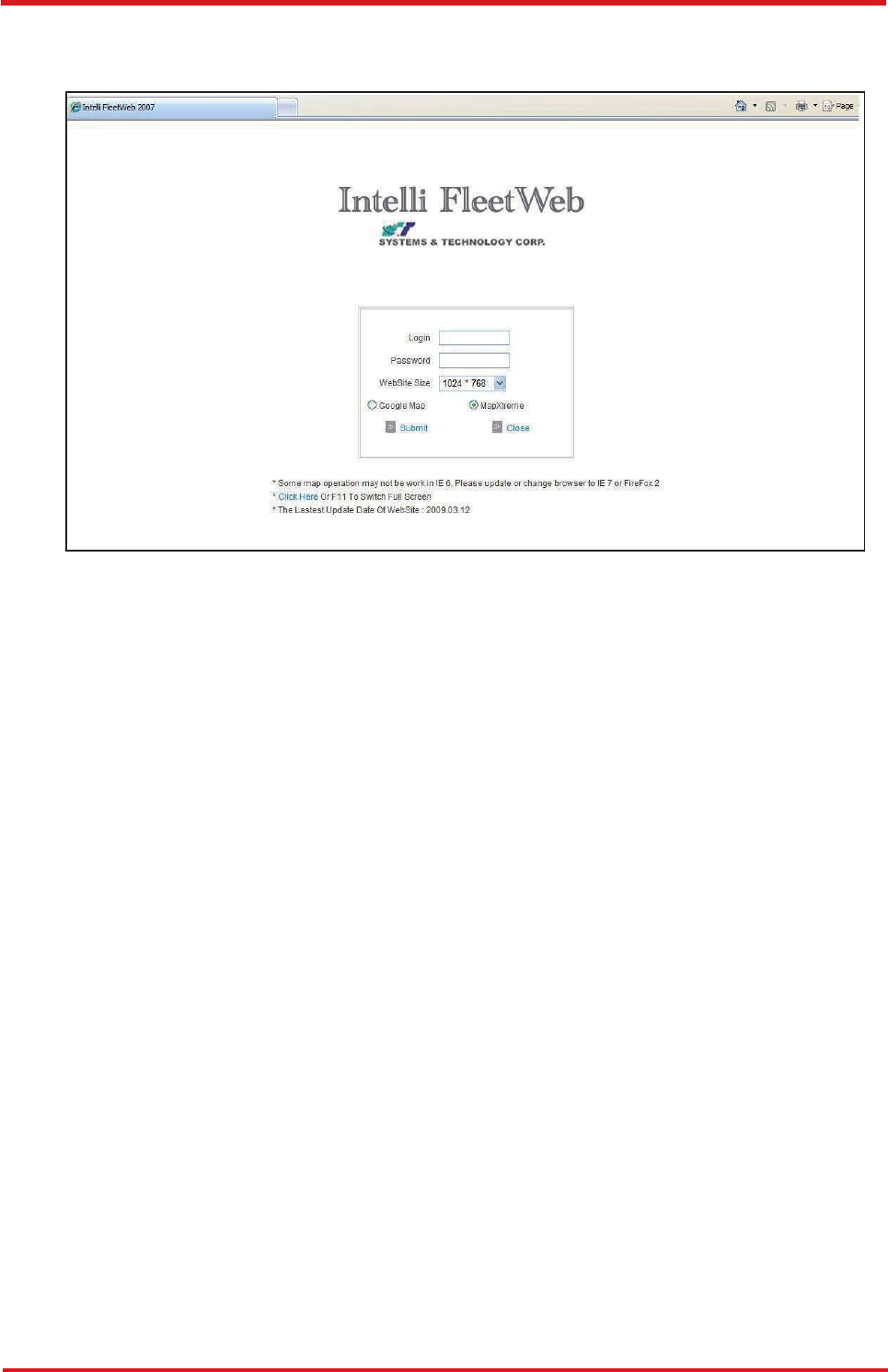
The main page of the Intelli FleetWeb appears as below:
CAREU U
3
V
ehicle
T
racker User Guide
32
Chapter 3
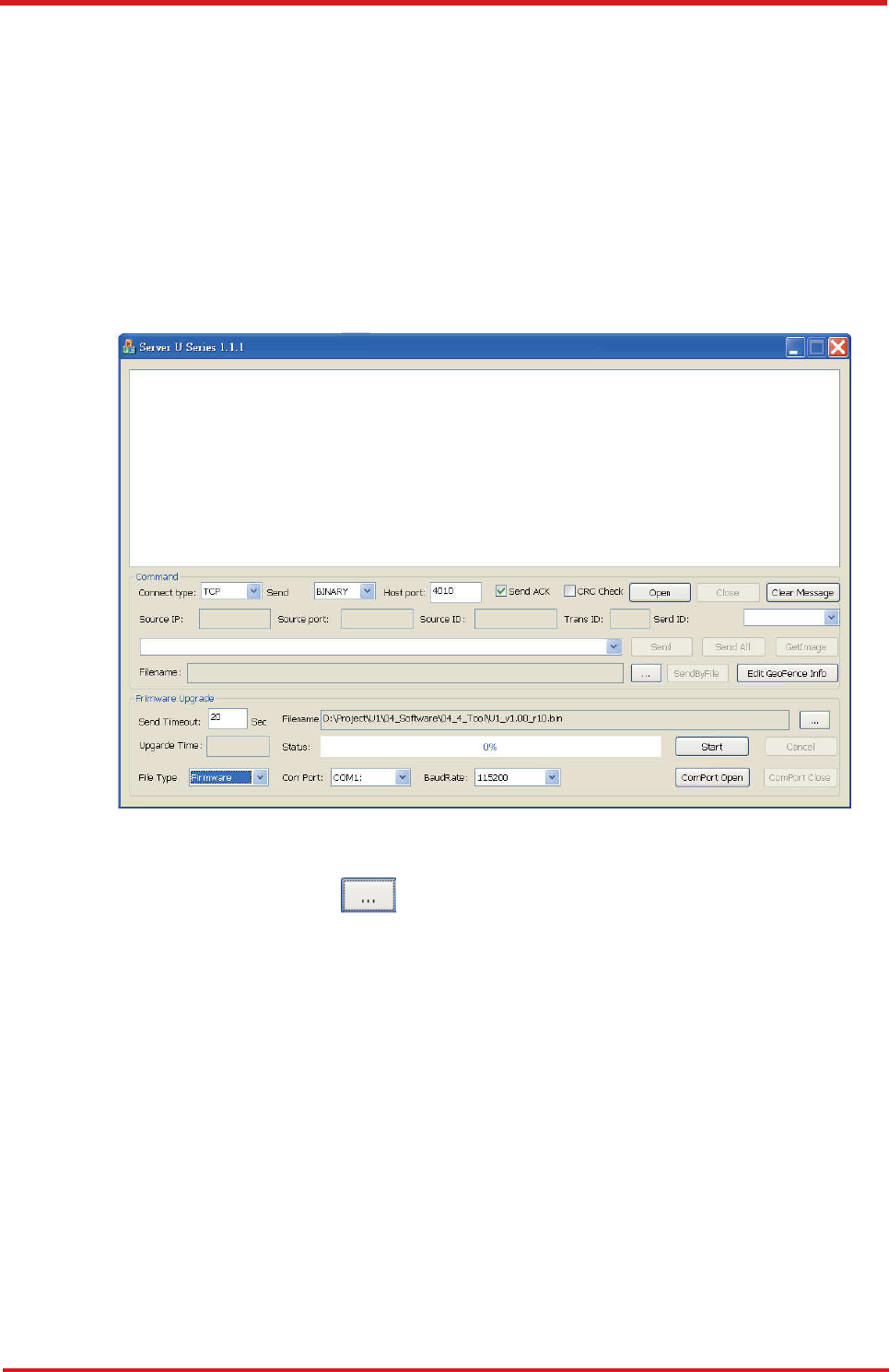
3.8 Firmware Upgrade
The firmware of the CAREU U3 can only be updated through USB interface. With the
firmware loader tool provided by S&T, firmware update can be done for the device. Such
firmware loader runs on Windows-based systems. To upgrade the firmware, follow the
procedure below:
1). Connect the device to your PC with the USB cable.
2). Connect the device to power.
3). Power on the device.
4). Run ServerUSeries.exe. A window displays as follows:
5). Press browse the button to browse to the firmware provided by S&T.
6). Press the Start button to run the firmware program.
7). After the writing progresses to 100%, it takes about 20 seconds for the update
to completes.
8). Firmware update completes.
CAREU U
3
V
ehicle
T
racker User Guide
Chapter 4
33
Chapter 4. Technical Specification
Characteristics
Dimensions (L x W x H)
108 x 72 x 31mm (with connector)
Weight 165g
Radio Performance
GSM Frequency Quad-band 850/900/1800/1900MHz
Operating Bands
B5, B2, B4
GSM Functionality / GPRS
GPRS Mode
Multislot class 10
GPRS Coding Scheme
CS1,CS2,CS3 and CS4
GSM Antenna
External
SIM Interface
SIM card 1.8V, 2.9V supported
GPS Functionality
Receiver
50 channels
Sensitivity (Tracking)
-160dBm
Antenna Type
External GPS active antenna, 3.3V
Connector
SMA female
GPS Protocol
NMEA 0183 Ver3.0
Onboard Components
MCU
32-bit microcontroller
Data Memory
8MB flash
Motion Sensor
3-axes acceleration sensor
Led Indicator
2. GPS and GSM

CAREU U
3
V
ehicle
T
racker User Guide
34
Chapter 3
Interface I/O
I/O Connector
1 connector, 10pin
Serial Connectors
3 RS-232 ports (configurable) : Standard version
2 RS-232 ports (configurable) : 1-Wire
®
version
Input Ports
Positive triggers: 2
Negative triggers: 2
Analog Inputs: 2 (0~30V, 12 bits)
Output Ports
Negative triggers: 3 (total 500mA)
Electrical
Power Source
DC 8V to 30V
Power Consumption
73 mA @ 12V (operating mode)
13 mA @ 12V (standby mode)
10 mA @ 12V (deep sleep mode)
Environment
Operating Temperature
–20 °C to +70 °C (without backup battery)
–20 °C to +60 °C (with backup battery)
Battery
Rechargeable Backup
Battery
1150mAH , support up to 8 days (based on data
transmission every 4 hours)
Note: The specification herein is subject to change without prior notice.

CAREU U
3
V
ehicle
T
racker User Guide
Chapter 5
35
Systems & Technology Corp. (S&T), founded in 1987, is a market leader in
Automatic Vehicle Locating (AVL) solutions, Geographical Information Systems (GIS)
and navigation. It has formed a professional development team to innovate the most
advanced and comprehensive GPS tracking products for the customers and has built
a global service network to provide non-stop services and support.
With the well-established marketing networks of over 100 distributors in the world,
S&T is your trustworthy tracking solution provider. For more product information,
please contact S&T by Email, phone or fax.
為維護隱私權
為維護隱私權為維護隱私權
為維護隱私權,
,,
,請妥適使用
請妥適使用請妥適使用
請妥適使用

CAREU U
3
V
ehicle
T
racker User Guide
Chapter 5
36
Federal Communication Commission Interference Statement
This device complies with Part 15 of the FCC Rules. Operation is subject to the
following two conditions: (1) This device may not cause harmful interference, and
(2) this device must accept any interference received, including interference that
may cause undesired operation.
This equipment has been tested and found to comply with the limits for a Class B
digital device, pursuant to Part 15 of the FCC Rules. These limits are designed to
provide reasonable protection against harmful interference in a residential
installation. This equipment generates, uses and can radiate radio frequency
energy and, if not installed and used in accordance with the instructions, may
cause harmful interference to radio communications. However, there is no
guarantee that interference will not occur in a particular installation. If this
equipment does cause harmful interference to radio or television reception, which
can be determined by turning the equipment off and on, the user is encouraged to
try to correct the interference by one of the following measures:
Reorient or relocate the receiving antenna.
Increase the separation between the equipment and receiver.
Connect the equipment into an outlet on a circuit different from that
to which the receiver is connected.
Consult the dealer or an experienced radio/TV technician for help.
FCC Caution: Any changes or modifications not expressly approved by the party
responsible for compliance could void the user's authority to operate this
equipment.
This transmitter must not be co-located or operating in conjunction with any other
antenna or transmitter.
Radiation Exposure Statement:
This equipment complies with FCC radiation exposure limits set forth for an
uncontrolled environment. This equipment should be installed and operated with
minimum distance 20cm between the radiator & your body.
Web Site
http://www.systech.com.tw
Email
avl@systech.com.tw
Phone
+886-2-2698-1599
Fax
+886-2-2698-1211