TAKAYA RP69W01 User Manual Correspondence Reference Number 7066
TAKAYA Corporation Correspondence Reference Number 7066
TAKAYA >
Contents
- 1. Operating Manual
- 2. Manual ClassB declaration
- 3. Correspondence Reference Number 7066
- 4. Reply to Reference Number 7066
Correspondence Reference Number 7066
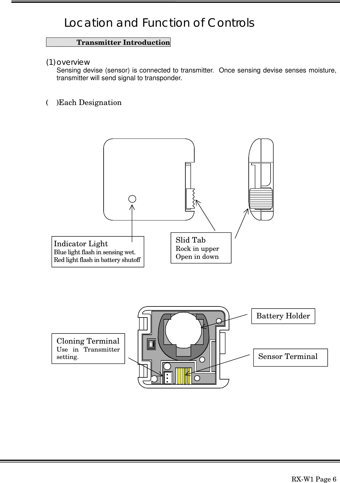
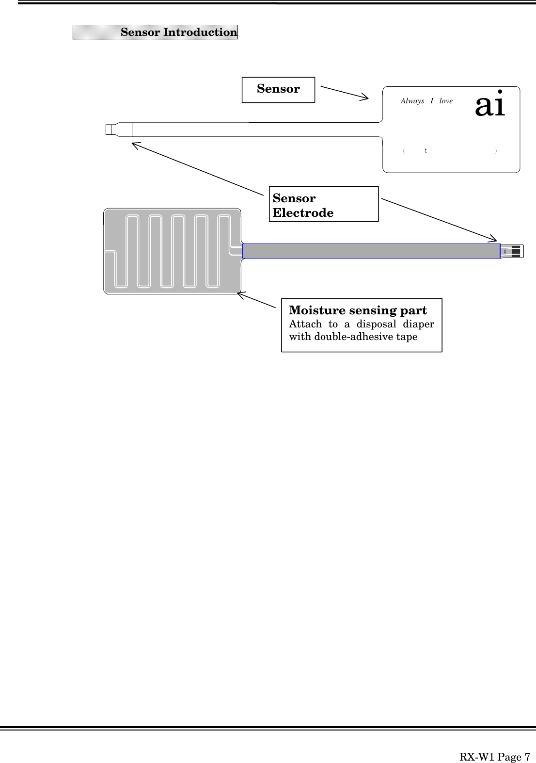
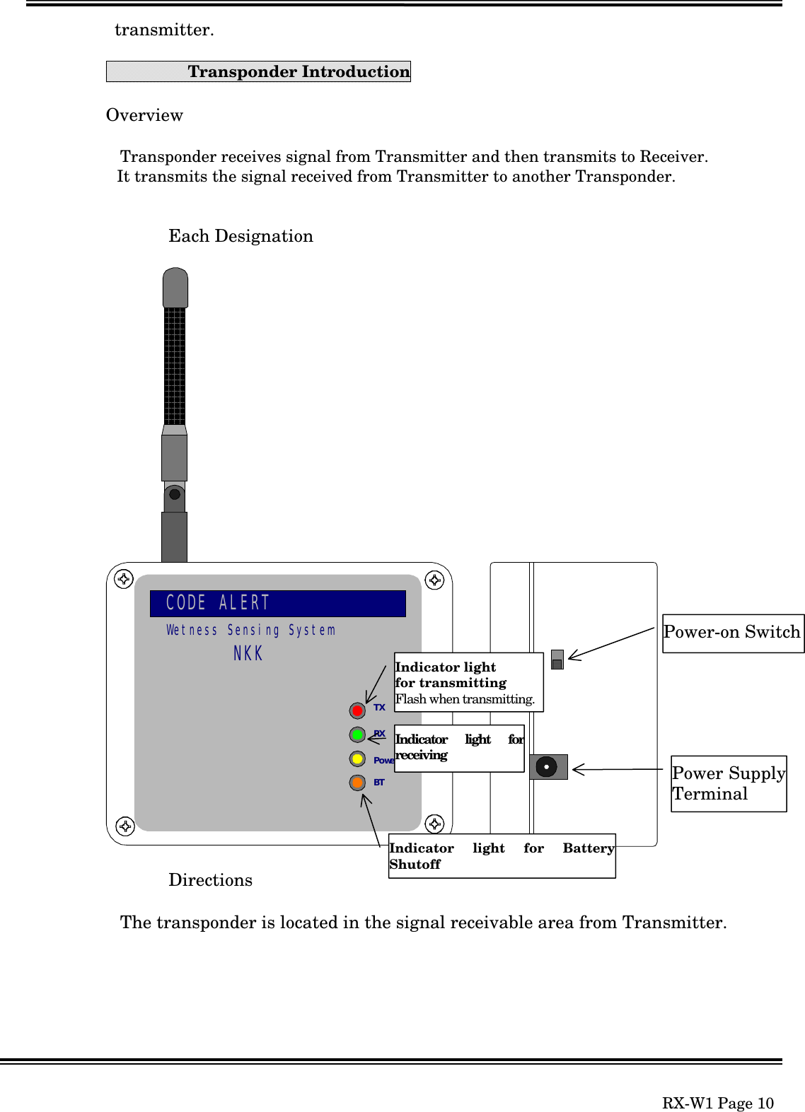
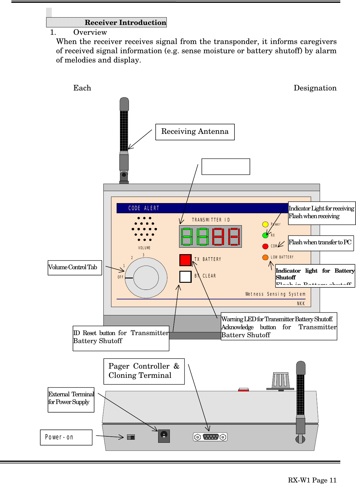
![RX-W1 Page 4[1] Wetness Sensing System(1) Overview’†Œp‹@ŒÅ’èŒ^ŽóM‹@Œg‘ÑŒ^•\ Ž¦‹@‘—M‹@—¾•êŽº‹ŽºThis Wetness Sensing System is comprised with transmitters, transpondersand receivers, which inform caregivers of sensing moisture in a diaper. Oncewetness sensor incorporated into diaper is aware of moisture, the transmitterincluding sensor puts out the signal to the transponder and then to the receiver.Handy-receiverStation-receiver(option)TransmitterTransponder](https://usermanual.wiki/TAKAYA/RP69W01.Correspondence-Reference-Number-7066/User-Guide-31049-Page-4.png)
![RX-W1 Page 254.Cominucations Protocol[PC] [Receiver][ Sensing DataTransfer]The Receivertransfers sensinginformation andbattery shutoffinformation.It transfers thedata periodicallyeach 5sec. …[BCC][CR]Transmitter ID (4-digits) which is sensingmoisture or batteryshutoff is transferredafter [:][K], and thenTransmitter status (”1”= Sensing moisture, ”2”= Battery shutoff, “3” =“1” and “2”) istransferred as single-digit. When multipleIDs or status istransferred, they arebroken by and added[BCC][CR] at the end.When there are nothingof transmittinginformation,[K][BCC][CR] aretransferred.BCC Calculating Methods:(STX) K(CMD) 0101(ID) 1(DATA) CN(BCC) Calculating RangeIt gets the SUM from CMD to DATA and divides into MSB 4bits and LSB 4bits, and then adds 40H and converts into 2 bytes word as hexadecimal.Example 1‘’‘’‘’414243LSBMSBExample 2 ‘’‘’‘’‘’‘’‘’‘’‘’‘’‘’‘’LSBMSB](https://usermanual.wiki/TAKAYA/RP69W01.Correspondence-Reference-Number-7066/User-Guide-31049-Page-25.png)
![RX-W1 Page 26ID TypesTransmitter IDTransmitter ID “0608” is 4-digit number, first 2-digit is Area ID and last two-digit isindividual unique ID.16 types of Area ID“01””16”(“01””10”[Hex])99 types of Unique ID“01””99”(“01””63”[Hex])Transmitter Clone ModeFig.4-1 CONNECTION OF CLONING UNITConnect the cloning unit like above chart, and start up PC and then run “HyperTerminal” of Windows accessory.Fig.4.2 Initial window of Hyper TerminalAfter running Hyper Terminal, the following window will open. Set as below.TRANSMITTERPC underWindows 95 or98RS232CStraight cableDCV](https://usermanual.wiki/TAKAYA/RP69W01.Correspondence-Reference-Number-7066/User-Guide-31049-Page-26.png)
![RX-W1 Page 29The following Transmitter start-up screen (Fig.4-4) will be displayed after settingCommunication Port and Communication protocol and insert a battery.Fig.4-4 Transmitter start-up screenAt this point when pushing C key within 5sec, the following screen (Fig.4-5) isdisplayed and Mode Set can be changed. Pushing Enter key terminates the setting.Fig.4-5Mode Set for Transmitter###### TX69W01 Ver.1.1 ######**** << Current Mode Status >> **** Current Detection=[ Capacitor ] Current Detection Level=[ High Level ] 1.Country Select = USA 2.ID No. = 0102 3.Resistor Detection Time = 3 (s) 4.Capacitor Detection Time = 10 (s) 5.STOP Time = 10 (s) 6.Serial Modulation Qty = 06Change Mode Set = [C] ? Execute = [Enter] ? ( Note: No Key, Auto Execute after 5 sec. )Current setting statusof Transmitter* **** << Current Mode Status >> **** Current Detection=[ Capacitor ] Current Detection Level=[ High Level ] 1.Country Select = USA 2.ID No. = 0102 3.Resistor Detection Time = 3 (s) 4.Capacitor Detection Time = 10 (s) 5.STOP Time = 10 (s) 6.Serial Modulation Qty = 06**** << Mode Set >> **** [1] = Country Select [2] = ID No. [3] = Resistor Detection Time [4] = Capacitor Detection Time [5] = STOP Time [6] = Serial Modulation Qty [0] = ENDSelect [1]-[6],[0] and Press [Enter]>Mode Set forTransmitter](https://usermanual.wiki/TAKAYA/RP69W01.Correspondence-Reference-Number-7066/User-Guide-31049-Page-29.png)
![RX-W1 Page 30Country Set (Select [] in Fig. 4-5)Fig.4-6Country SetTransmitter ID Set (Select [] in Fig.4-5)Fig.4-7Transmitter ID SetSetting of Resistor Detection Time. (Select [] in Fig.4-5)Fig.4-8 Setting of Resistor Detection TimeSetting of Capacitor Detection Time. (Select [] in Fig.4-5)Fig.4-9 Setting of Capacitor Detection Time**** << Country Set >> **** [ESC]=STOPCountry = USA[1]=USA [2]=JAPANInput [1]or[2] ? and Press [Enter]>1Current countryCountry changed**** << ID No. Set >> **** [ESC]=STOPID No. = 0112Input ID No. [0000]-[9999] ? and Press [Enter]>0101Current IDID changed**** << Resistor Detection Time Set >> ****[ESC]=STOPResistor Detection Time = 3 (s)Input [1]-[9] ? and Press [Enter]>2Current Detection TimeDetection Time changedunit: [sec]**** << Capacitor Detection Time Set >> ****[ESC]=STOPCapacitor Detection Time = 10 (s)Input [01]-[99] ? and Press [Enter]>09Current Detection TimeDetection Time changedunit: [sec]](https://usermanual.wiki/TAKAYA/RP69W01.Correspondence-Reference-Number-7066/User-Guide-31049-Page-30.png)
![RX-W1 Page 31Setting of Transmission Stop Time. (Select [] in Fig.4-5)Fig.4-10 Setting of Transmission Stop TimeSetting of Modulation number of times. (Select [] in Fig.4-5)Fig.4-11 Setting of Modulation number of timesSetting Mode(SW1-1 & SW1-4 ON)At this point when pushing C key within 5sec, Mode Set can be changed.Fig.4-12 Setting ModeSelect [] in Fig. 4-5, and then CLONING MODE will be terminated.After terminated CLONINGMODE, it returns to Normal Mode.Fig.4-13 CLONINGMODE Termination**** << Stop Time Set >> **** [ESC]=STOPStop Time = 10 (s)Input [10]-[99] ? and Press [Enter]>11Current Stop TimeIn case of USA, Stop time can bechanged from 10sec to 99sec.**** << Serial Modulation Qty Set >> **** [ESC]=STOPSerial Modulation Qty = 06Input [01]-[06] ? and Press [Enter]>05Current Modulationnumber of timesIn case of USA, Modulationnumber of times can be changedfrom 01 to 06.Select [1]-[7],[0] and Press [Enter]>0**** << End of Mode Set >> ******* << Current Mode Status >> **** 1. High Level of Capacitor Detection = 048 2. Low Level of Capacitor Detection = 100 3. High Level of Resistor Detection = 152 4. Low Level of Resistor Detection = 110Change Mode Set = [C] ? Execute = [Enter] ? ( Note: No Key, Auto Execute after 5 sec. )Current Limit Level](https://usermanual.wiki/TAKAYA/RP69W01.Correspondence-Reference-Number-7066/User-Guide-31049-Page-31.png)
![RX-W1 Page 32Transponder Clone ModeFig.4-14 CONNECTION OF CLONING UNITConnect the cloning unit like above chart, and start up PC and then run “HyperTerminal” of Windows accessory.When TRANSPONDER turned ON, the following screen (Fig.4-15) is displayed.Fig.4-15 Transponder set-up screenAt this point when pushing C key within 5sec, the following screen (Fig.4-16) isdisplayed and Mode Set can be changed. Pushing Enter key terminates the setting.Fig.4-16Setting for TransponderInsert to CN2 ofTRANSPONDERPC underWindows 95 or98RS232CStraight CableConversion Cable###### RP69W01 Ver.1.0 ###### 1. Repeater Retry Qty = [3] (x10sec)Change Mode Set = [C] ? Execute = [Enter] ?Note: No Key, Auto Execute after 5 sec.Current Status ofTransponder setting **** << Current Mode Status >> **** 1. Repeater Retry Qty = [3] (x10sec)**** << Mode Set >> **** [1] = Repeater Retry Qty Set [0] = ENDSelect [1],[0] and Press [Enter]>1](https://usermanual.wiki/TAKAYA/RP69W01.Correspondence-Reference-Number-7066/User-Guide-31049-Page-32.png)
![RX-W1 Page 33Setting of Transponder Re-try number of times (Select [] in Fig.4-16)It means even the signal from Transponder is aborted, it holds IDs for re-trynumber of times multiplied by 10sec.Fig.4-17 Setting of Transponder Re-try number of timesSelect [] in Fig. 4-5, and then CLONING MODE will be terminated.After terminated CLONINGMODE, it returns to Normal Mode.Fig.4-18 CLONINGMODE Termination>1Repeater Retry Qty = [3]Repeater Retry Qty [1]-[9]x10s =4Current Retry number of timesRetry number of times changed.unit: [10sec]**** << Mode Set >> **** [1] = Repeater Retry Qty Set [0] = ENDSelect [1],[0] and Press [Enter]>0Mode set end.](https://usermanual.wiki/TAKAYA/RP69W01.Correspondence-Reference-Number-7066/User-Guide-31049-Page-33.png)
![RX-W1 Page 34Receiver Clone ModeFig.4-19 CONNECTION OF CLONING UNITConnect the cloning unit like above chart, and start up PC and then run “Hyper Terminal” of Windows accessory.When Receiver turned ON, the following screen (Fig.4-20) is displayed.Fig.4-20 Initial screen of ReceiverRECEIVER PC underWindows 95 or98RS232CStraight###### RX69W01 Ver.1.1 ###### 1. Melody Channel for Area ID 2. Melody Output Mode = [ Repeat ] 3. Display switching time for multiple alarmed IDs = [3]x0.5 (sec) 4. Display holding time for alarmed ID = [3]x10 (sec) 5. Confirm each melodiesChange Mode Set = [C] ? Execution = [Enter] ?Current Status ofReceiver setting](https://usermanual.wiki/TAKAYA/RP69W01.Correspondence-Reference-Number-7066/User-Guide-31049-Page-34.png)
![RX-W1 Page 35At this point when pushing C key within 5sec, the following screen (Fig.4-5) isdisplayed and Mode Set can be changed. Pushing Enter key terminates the setting.Fig.4-21 Mode Set for ReceiverChange Melody for Area IdFig.4-22 Setting Melody Channel for Area ID **** << Current Mode Status >> **** 1. Melody Channel for Area ID 2. Melody Output Mode = [ Repeat ] 3. Display switching time for multiple alarmed IDs = [3]x0.5 (sec) 4. Display holding time for alarmed ID = [3]x10 (sec) 5. Confirm each melodies**** << Set of Mode >> **** Cancel=ESC [1] = Melody Channel for Area ID [2] = Melody Output Mode [3] = Display switching time for multiple alarmed IDs [4] = Display holding time for alarmed ID [5] = Confirm each melodiesSelect [1]-[5] and Press [Enter]>1Current Status ofReceiver setting **** << Change Melody for Area ID >> **** Cancel=ESC ID Melody CH. ID Melody CH. 1 = [01] 9 = [09] 2 = [02] 10 = [10] 3 = [03] 11 = [11] 4 = [04] 12 = [12] 5 = [05] 13 = [13] 6 = [06] 14 = [14] 7 = [07] 15 = [15] 8 = [08] 16 = [16]Select [01]-[16] and Press [Enter]>01](https://usermanual.wiki/TAKAYA/RP69W01.Correspondence-Reference-Number-7066/User-Guide-31049-Page-35.png)
![RX-W1 Page 36Change Melody for Area Id (Select [] in Fig.4-22)Fig.4-23 Setting Melody Channel for Area ID**** << Change Melody for Area ID >> **** Cancel=ESC [01] = Alarm1 [02] = Alarm2 [03] = Alarm3 [04] = Alarm4 [05] = Yankee Doodle [06] = Oh! Susanna [07] = Grandfathers Clock [08] = Chitty Chitty Bang Bang [09] = De Camptown Races [10] = If Youre Happy And You Know It, Clap Your Hands [11] = Mary Had A Little Lamb [12] = Edelweiss [13] = Bridge Over Troubled Water [14] = I have Been Working On The Railroad [15] = Do-Re-Mi [16] = Battle Hymn of The Republic [17] = Alarm ErrSelect of Melody Name [01]-[17] and Press [Enter] Area ID 1 = Melody [01]Melody Channel for Area ID 1 =>01List of Melody nameMelody ID No. changed](https://usermanual.wiki/TAKAYA/RP69W01.Correspondence-Reference-Number-7066/User-Guide-31049-Page-36.png)
![RX-W1 Page 37Setting of Melody Output Method (Select [] in Fig.4-21)Fig.4-24 Melody output method SetDisplay switching time for multiple ID’s Set (Select [] in Fig.4-21)Fig.4-25 Changing Display holding time for Multiple IDs**** << Melody Output Mode >> **** Cancel=ESC [1] = One Shot 1 [2] = One Shot 2 [3] = RepeatSelect [1]-[3] and Press [Enter]Melody Output Mode = [ Repeat ]Melody Output Mode =>1Current Melody output methodMelody Output method for changing*** << Display switching time for multiple alarmed IDs >> ****Cancel=ESC [1] = 0.5 Sec [2] = 1.0 Sec [3] = 1.5 Sec [4] = 2.0 Sec [5] = 2.5 Sec [6] = 3.0 Sec [7] = 3.5 Sec [8] = 4.0 Sec [9] = 4.5 SecSelect [1]-[9] and Press [Enter]Display switching time for multiple alarmed IDs = [3]x0.5 (sec)Display switching time for multiple alarmed IDs =>3Current holding time for displayHolding time for display changed](https://usermanual.wiki/TAKAYA/RP69W01.Correspondence-Reference-Number-7066/User-Guide-31049-Page-37.png)
![RX-W1 Page 38Display holding time for alarmed ID Set (Select [4] in Fig.4-21)Fig.4-26 Changing Display holding time**** << Display holding time for alarmed ID >> **** Cancel=ESC [1] = 10 Sec [2] = 20 Sec [3] = 30 Sec [4] = 40 Sec [5] = 50 Sec [6] = 60 Sec [7] = 70 Sec [8] = 80 Sec [9] = 90 SecSelect [1]-[9] and Press [Enter]Display holding time for alarmed ID = [3]x10 (sec)Display holding time for alarmed ID =>3Current holding time for displayHolding time for display changed](https://usermanual.wiki/TAKAYA/RP69W01.Correspondence-Reference-Number-7066/User-Guide-31049-Page-38.png)
![RX-W1 Page 39Confirm each melodies (Select [] Confirm in Fig.4-21)Fig.4-27 Melody ConfirmationPush [Esc] in Fig. 4-21, and then CLONING MODE will be terminated.After terminated CLONINGMODE, it returns to Normal Mode.Fig.4-28 CLONINGMODE Termination***** << Current Mode Status >> **** 1. Melody Channel for Area ID 2. Melody Output Mode = [ One Shot 1 ] 3. Display switching time for multiple alarmed IDs = [3]x0.5 (sec) 4. Display holding time for alarmed ID = [3]x10 (sec) 5. Confirm each melodies**** << Set of Mode >> **** Cancel=ESC [1] = Melody Channel for Area ID [2] = Melody Output Mode [3] = Display switching time for multiple alarmed IDs [4] = Display holding time for alarmed ID [5] = Confirm each melodiesSelect [1]-[5] and Press [Enter]>**** << Confirm each melodies >> **** Cancel=ESC [01] = Alarm1 [02] = Alarm2 [03] = Alarm3 [04] = Alarm4 [05] = Yankee Doodle [06] = Oh! Susanna [07] = Grandfathers Clock [08] = Chitty Chitty Bang Bang [09] = De Camptown Races [10] = If Youre Happy And You Know It, Clap Your Hands [11] = Mary Had A Little Lamb [12] = Edelweiss [13] = Bridge Over Troubled Water [14] = I have Been Working On The Railroad [15] = Do-Re-Mi [16] = Battle Hymn of The Republic [17] = Alarm ErrSelect of Melody Name [01]-[17] and Press [Enter] Current Melody CH. = [01] Request Melody CH. =>List of Melody nameMelody number confirmed](https://usermanual.wiki/TAKAYA/RP69W01.Correspondence-Reference-Number-7066/User-Guide-31049-Page-39.png)