TAKAYA RP69W01 User Manual Reply to Reference Number 7066
TAKAYA Corporation Reply to Reference Number 7066
TAKAYA >
Contents
- 1. Operating Manual
- 2. Manual ClassB declaration
- 3. Correspondence Reference Number 7066
- 4. Reply to Reference Number 7066
Reply to Reference Number 7066
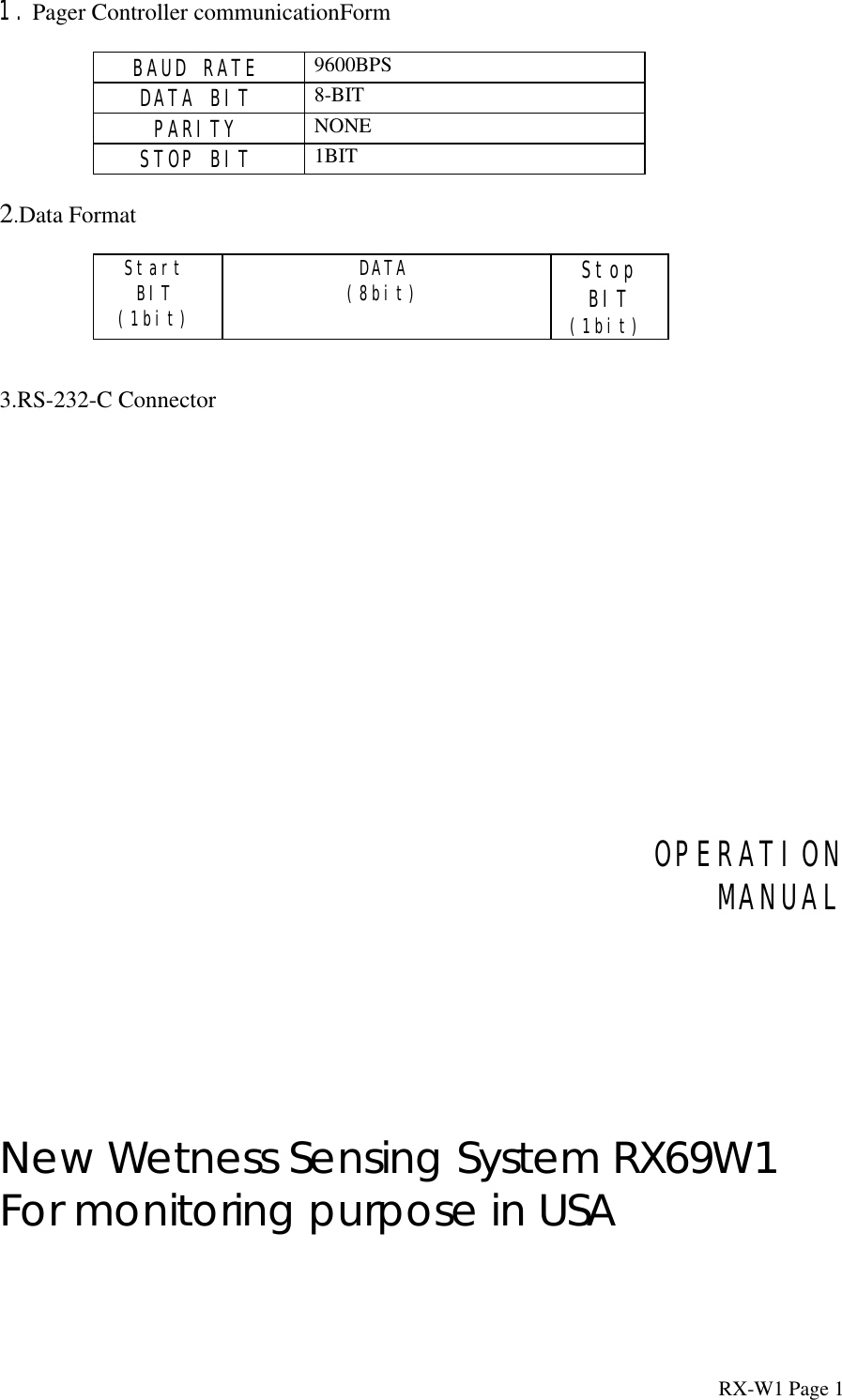
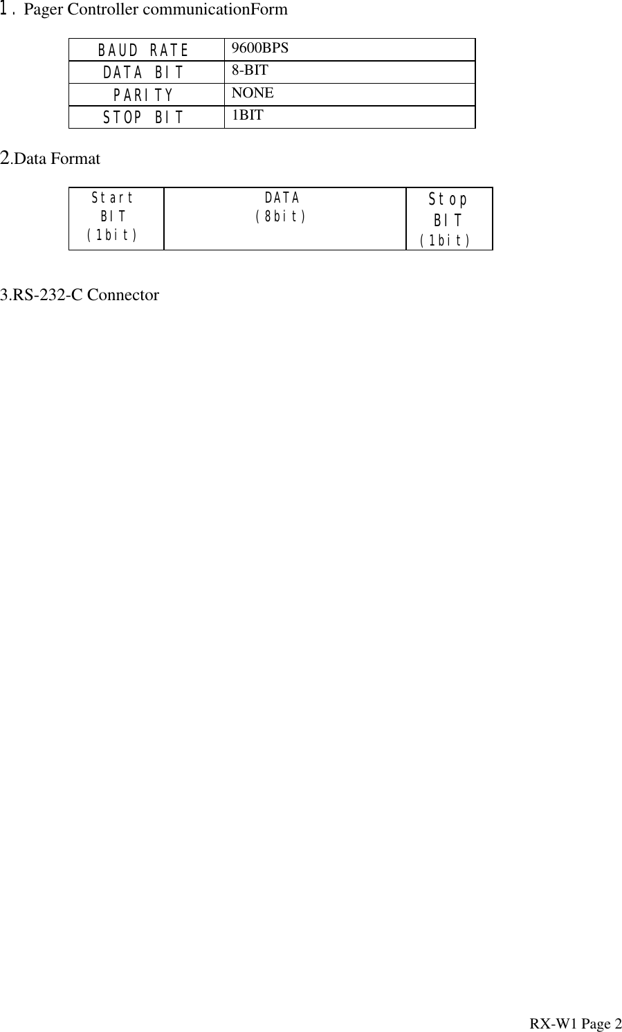
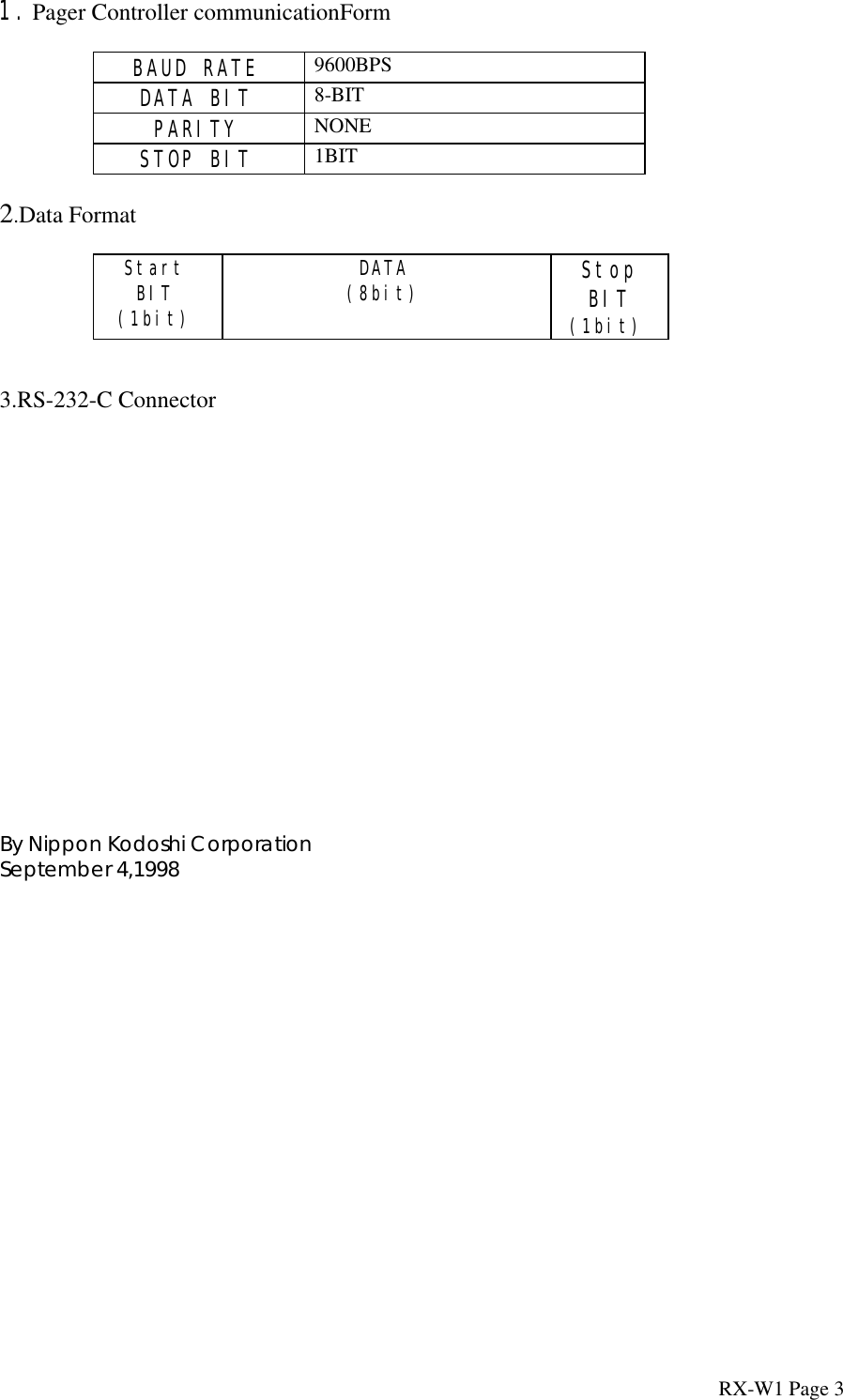
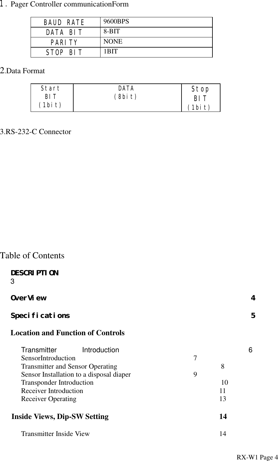
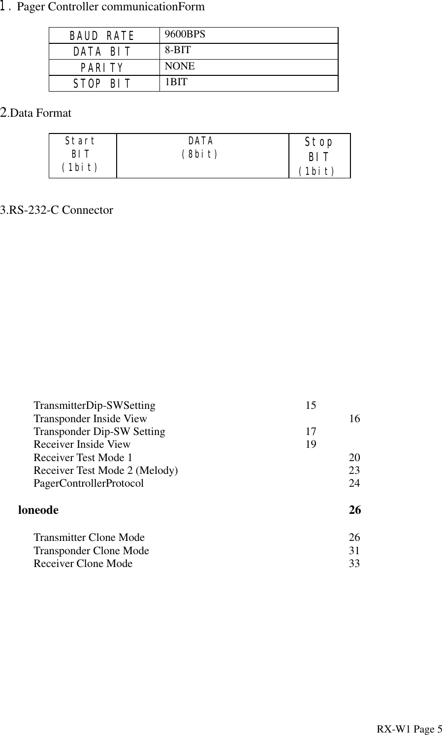
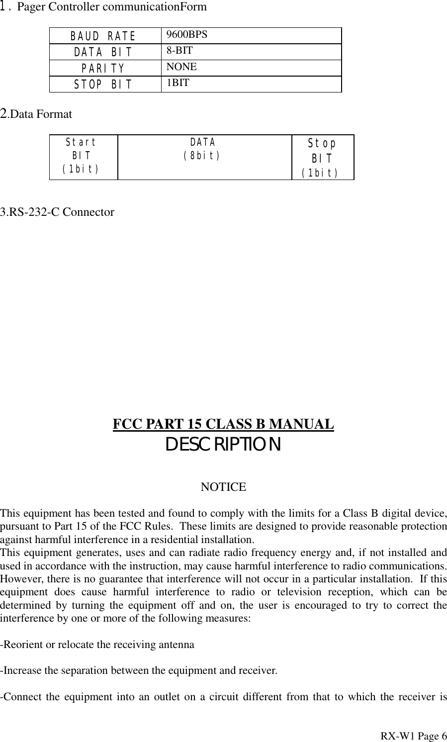
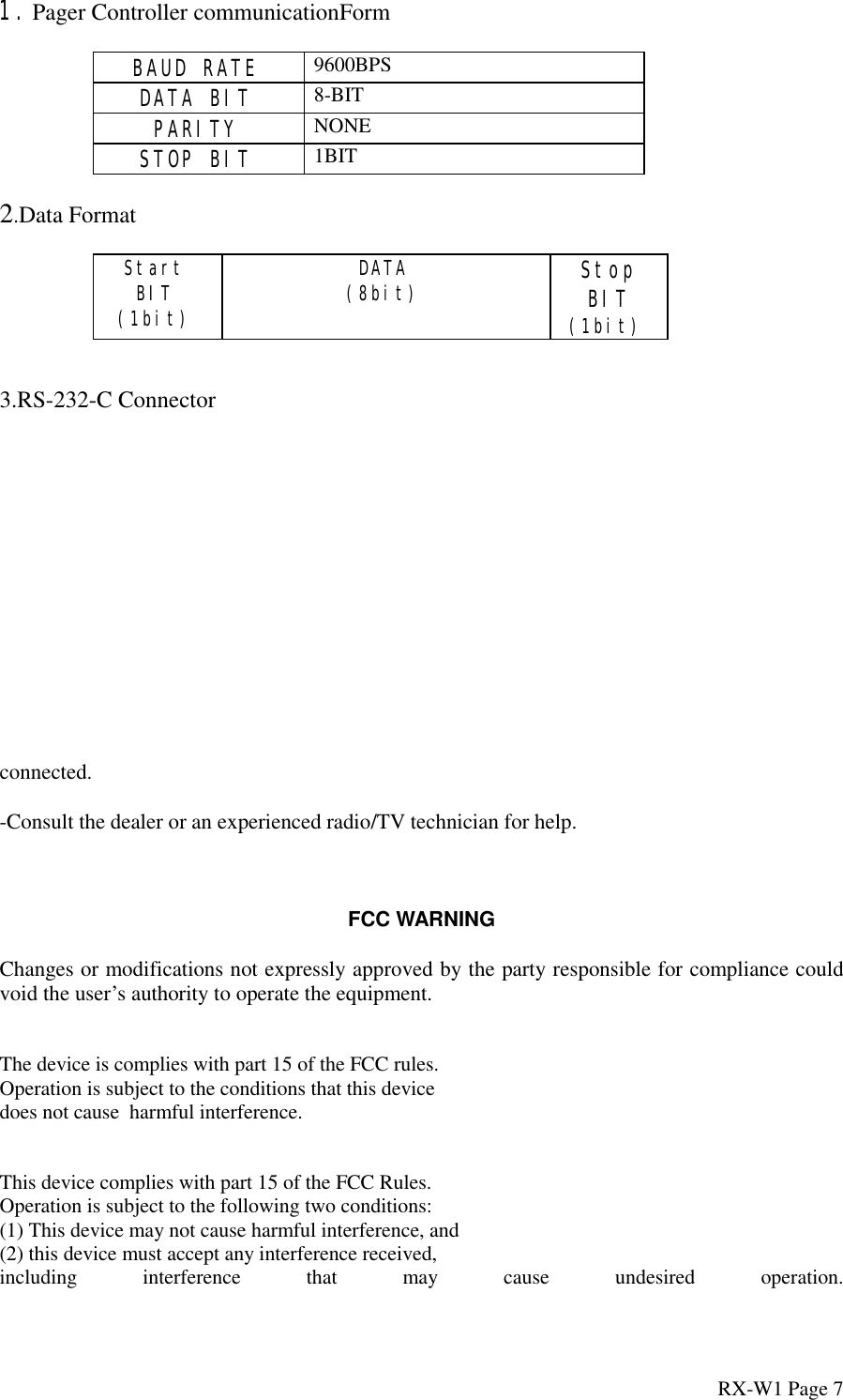
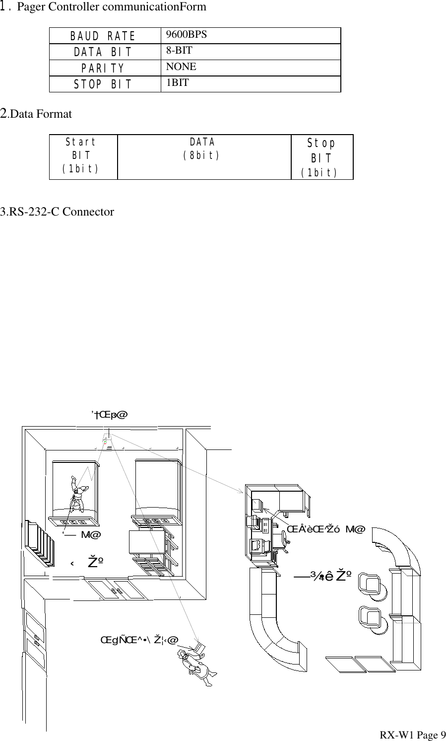
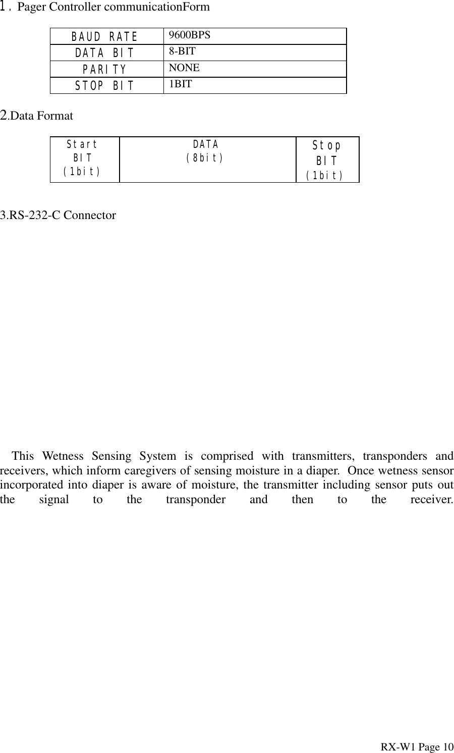
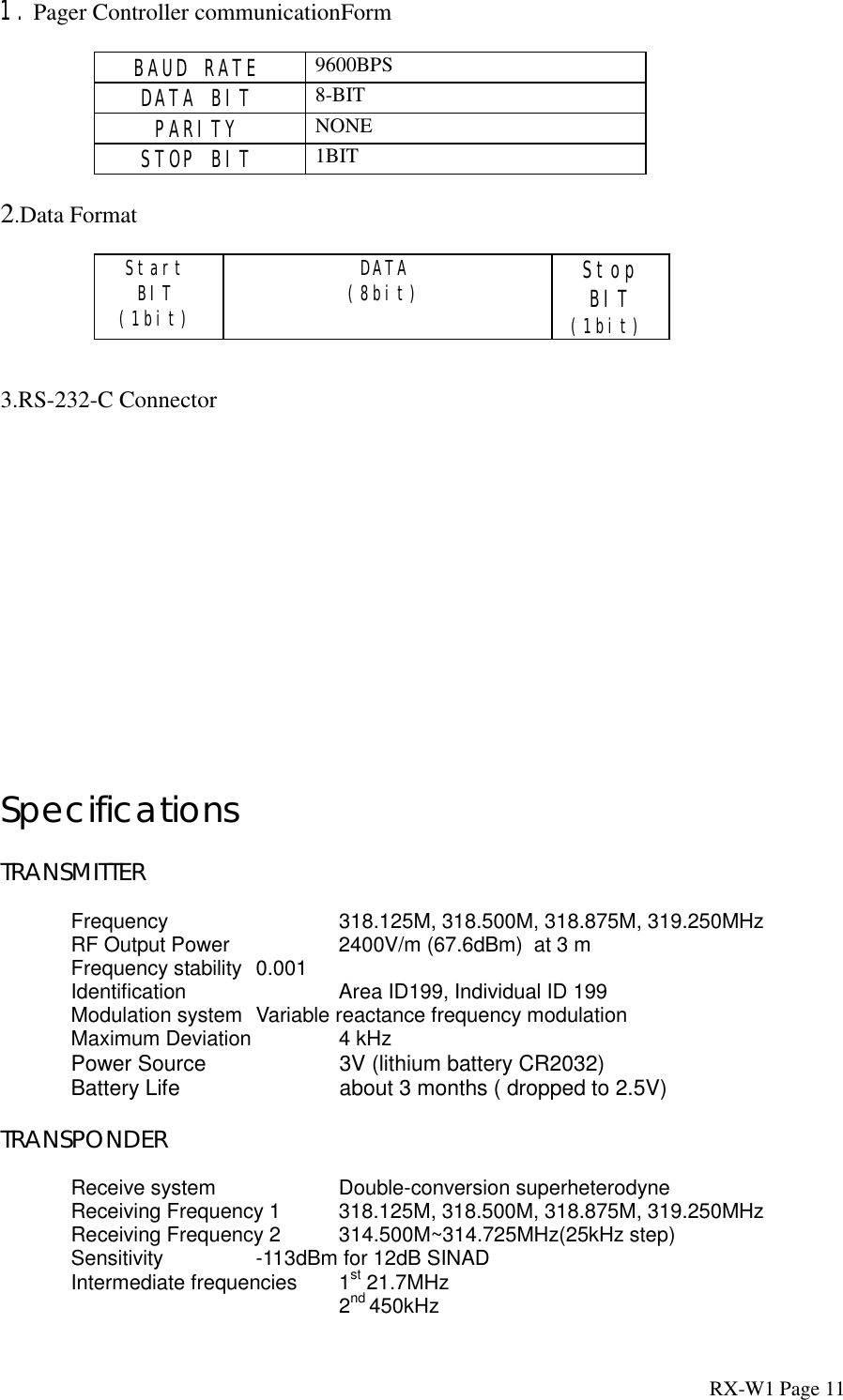
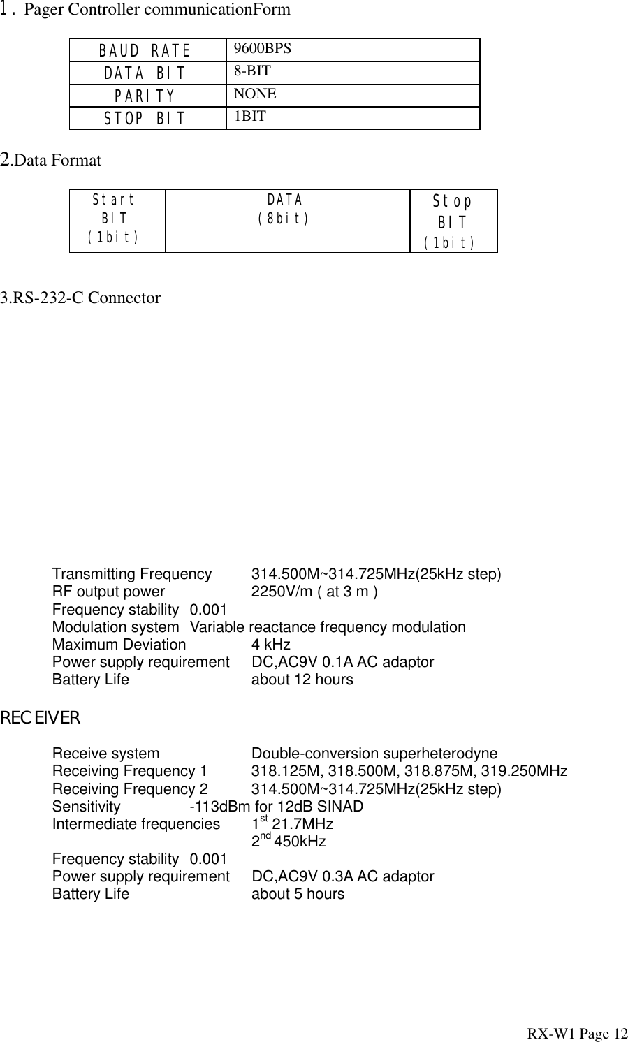
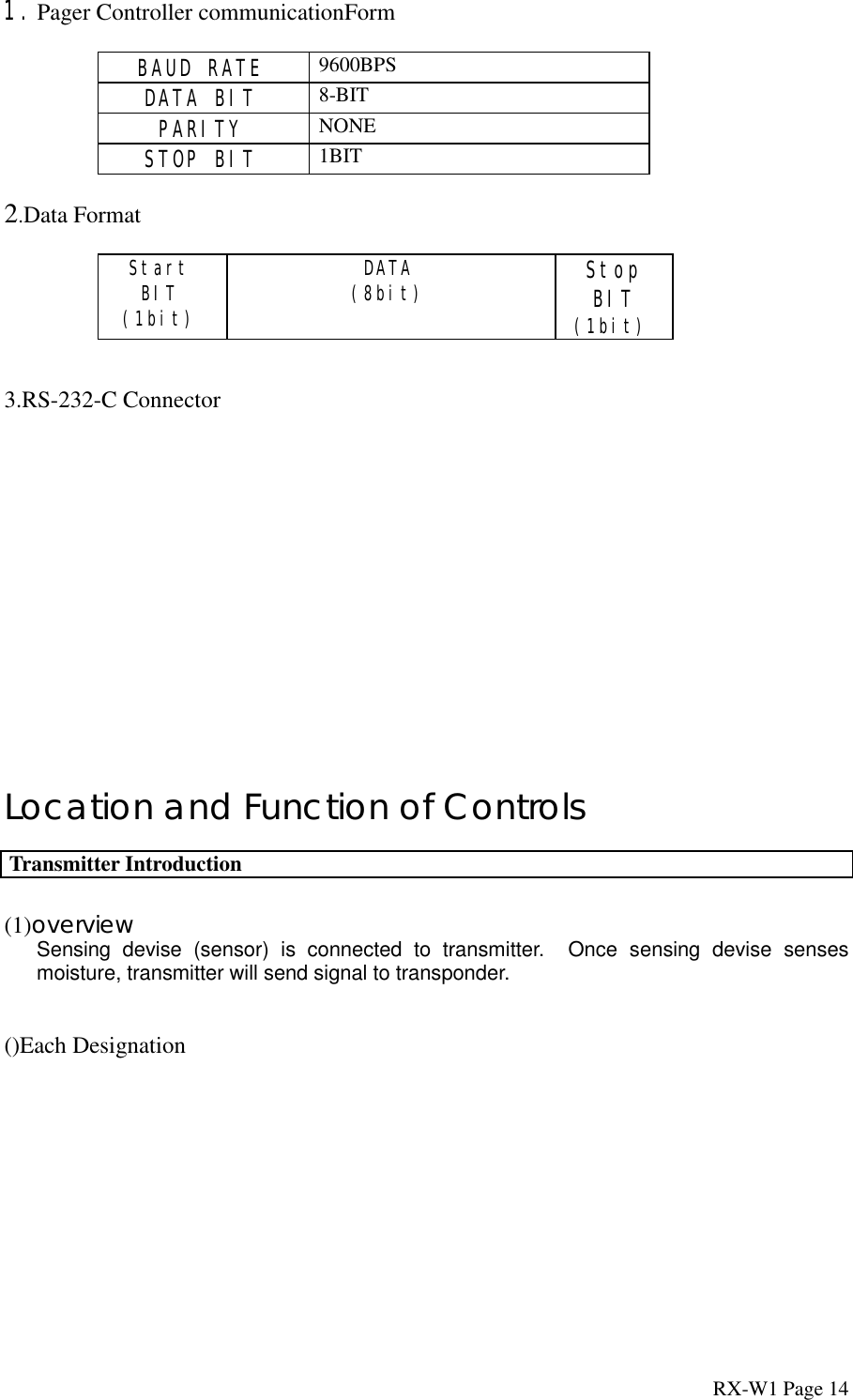
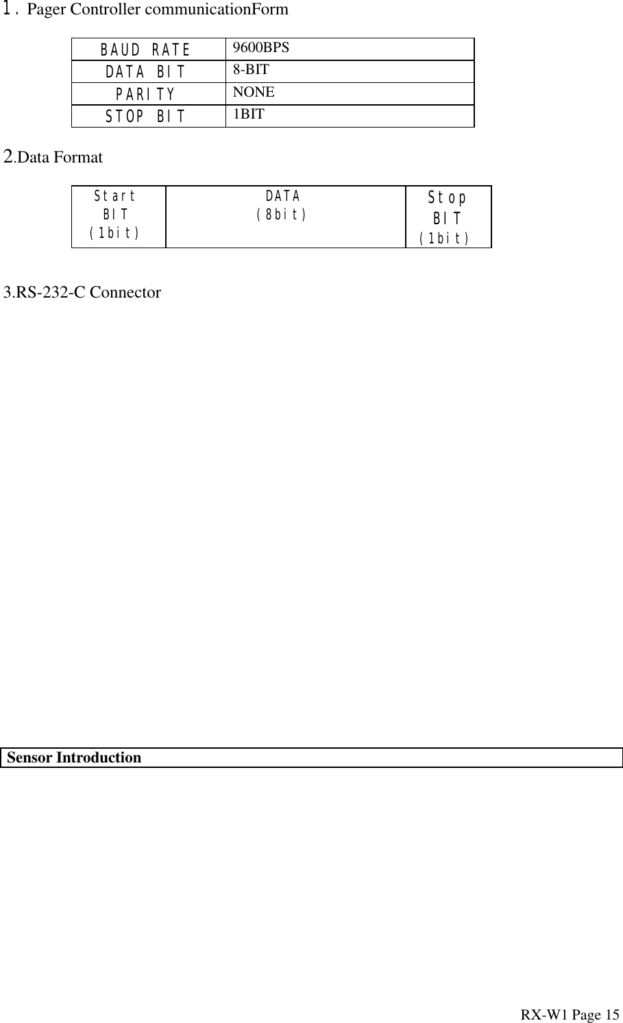
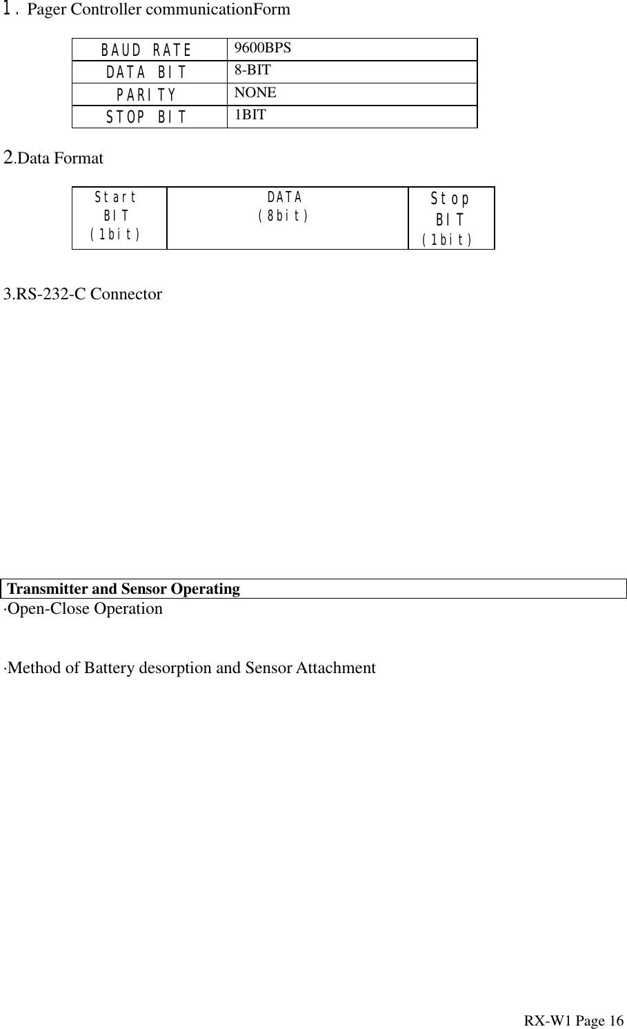
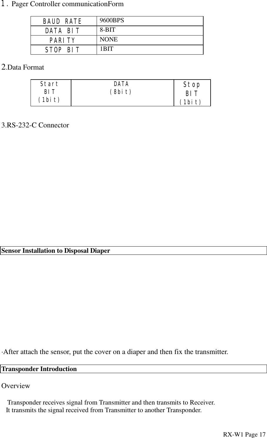
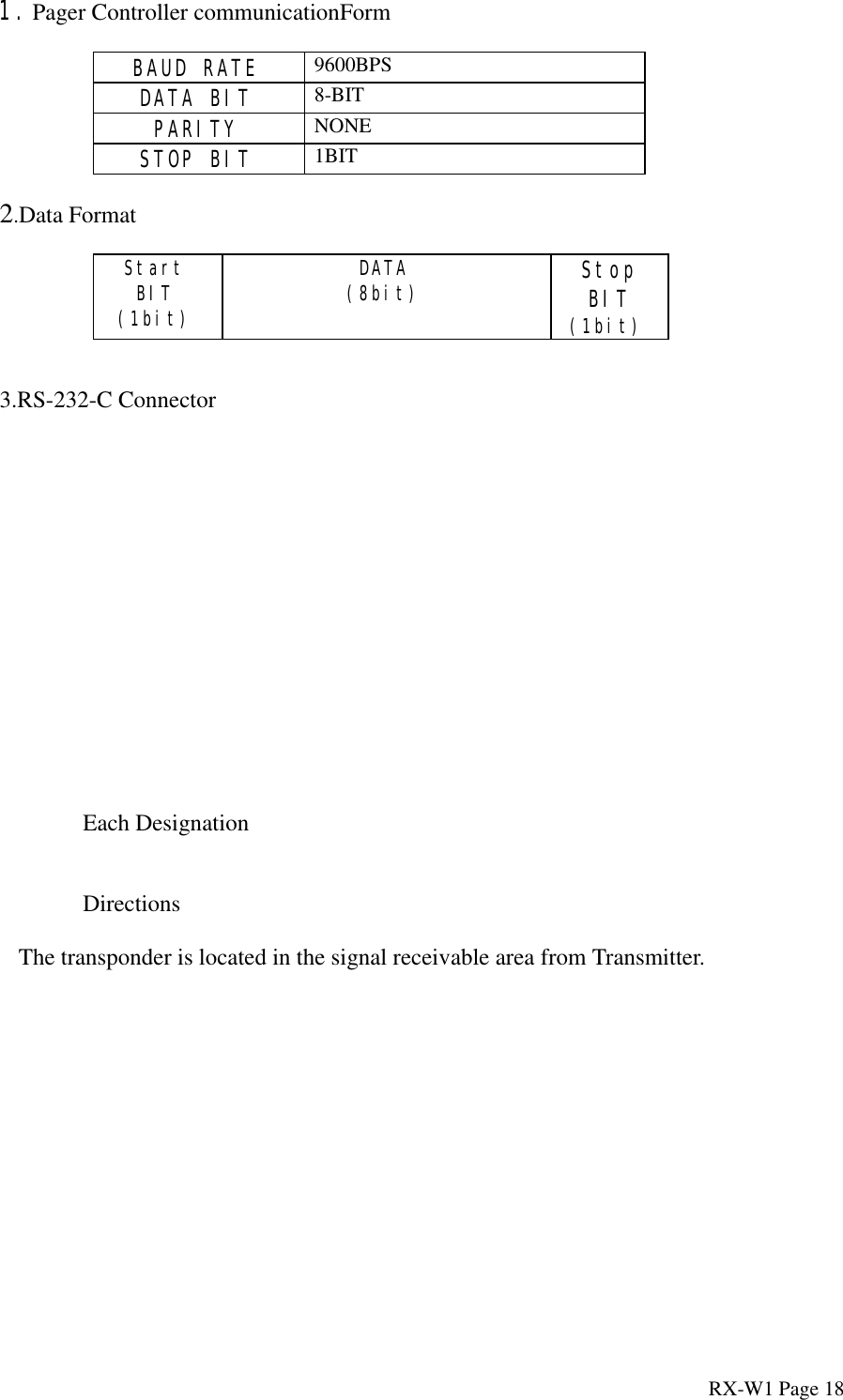
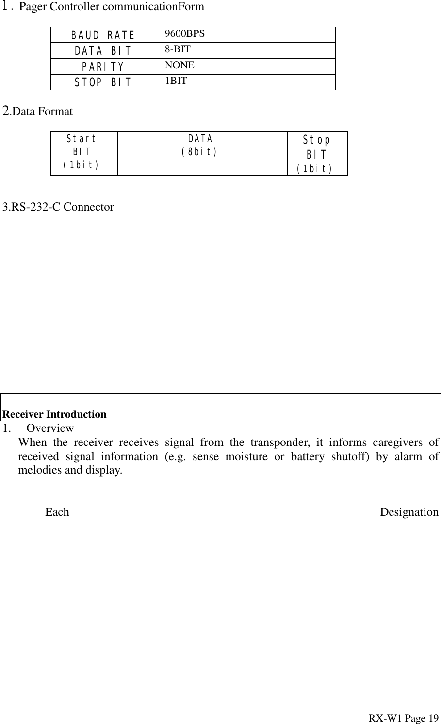
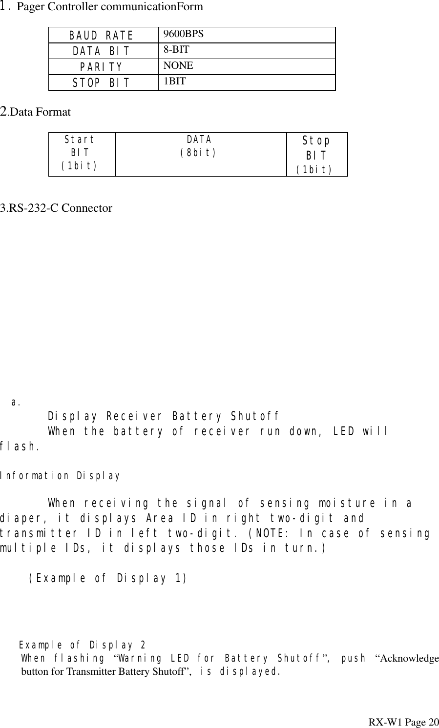
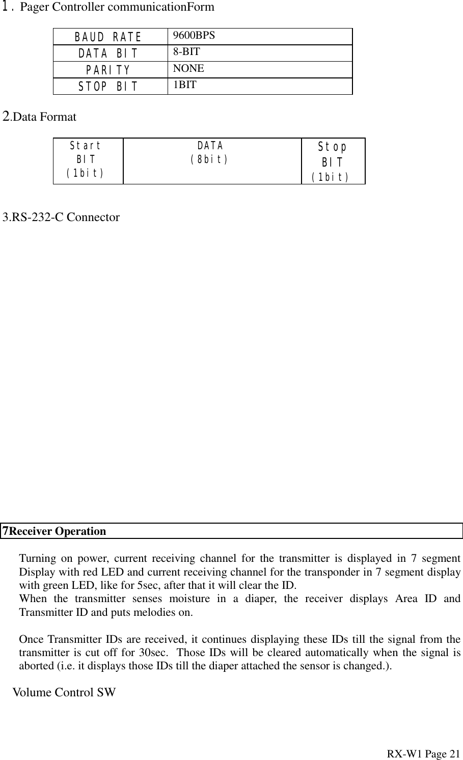
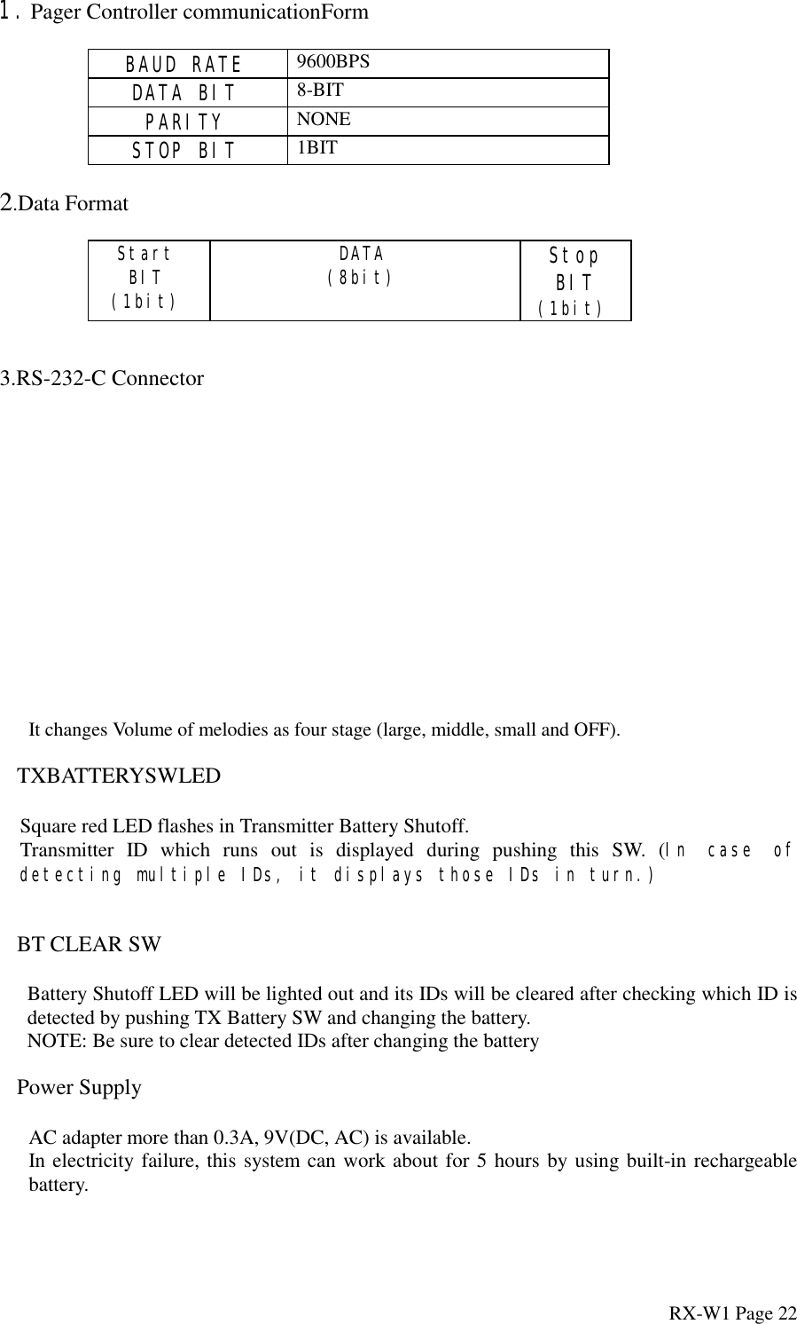
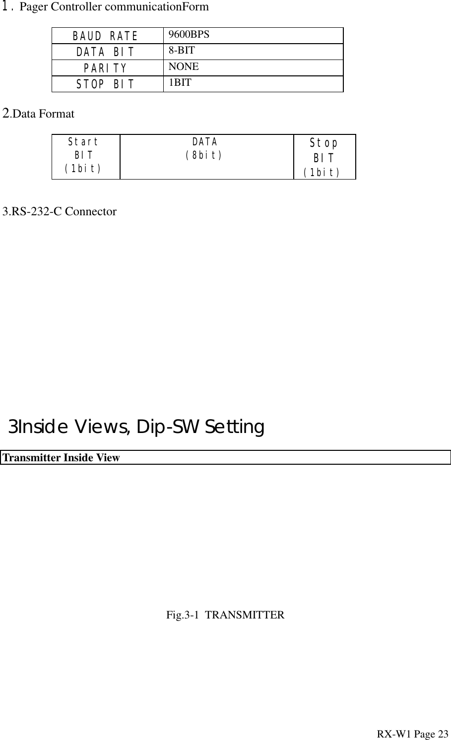
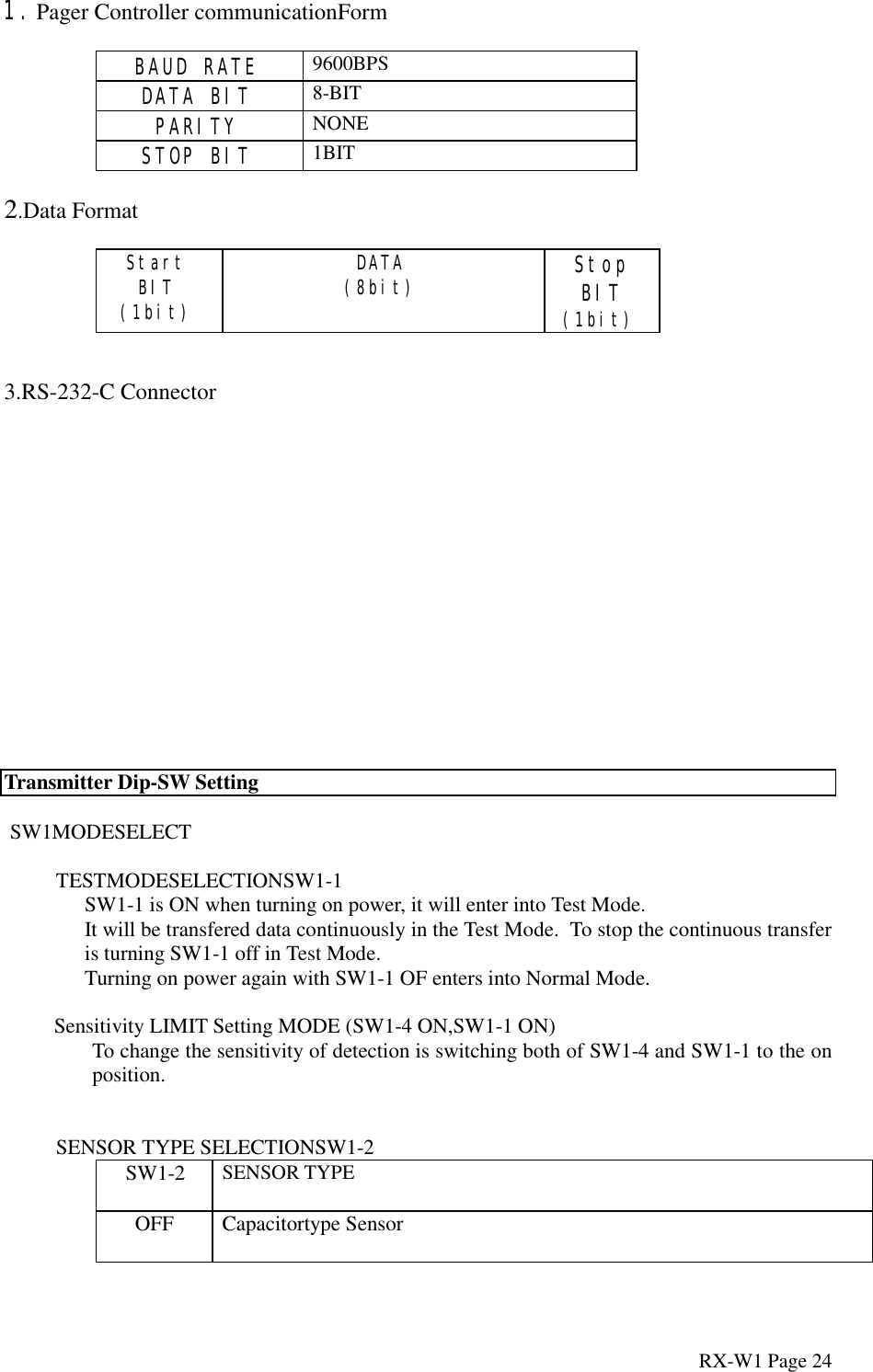
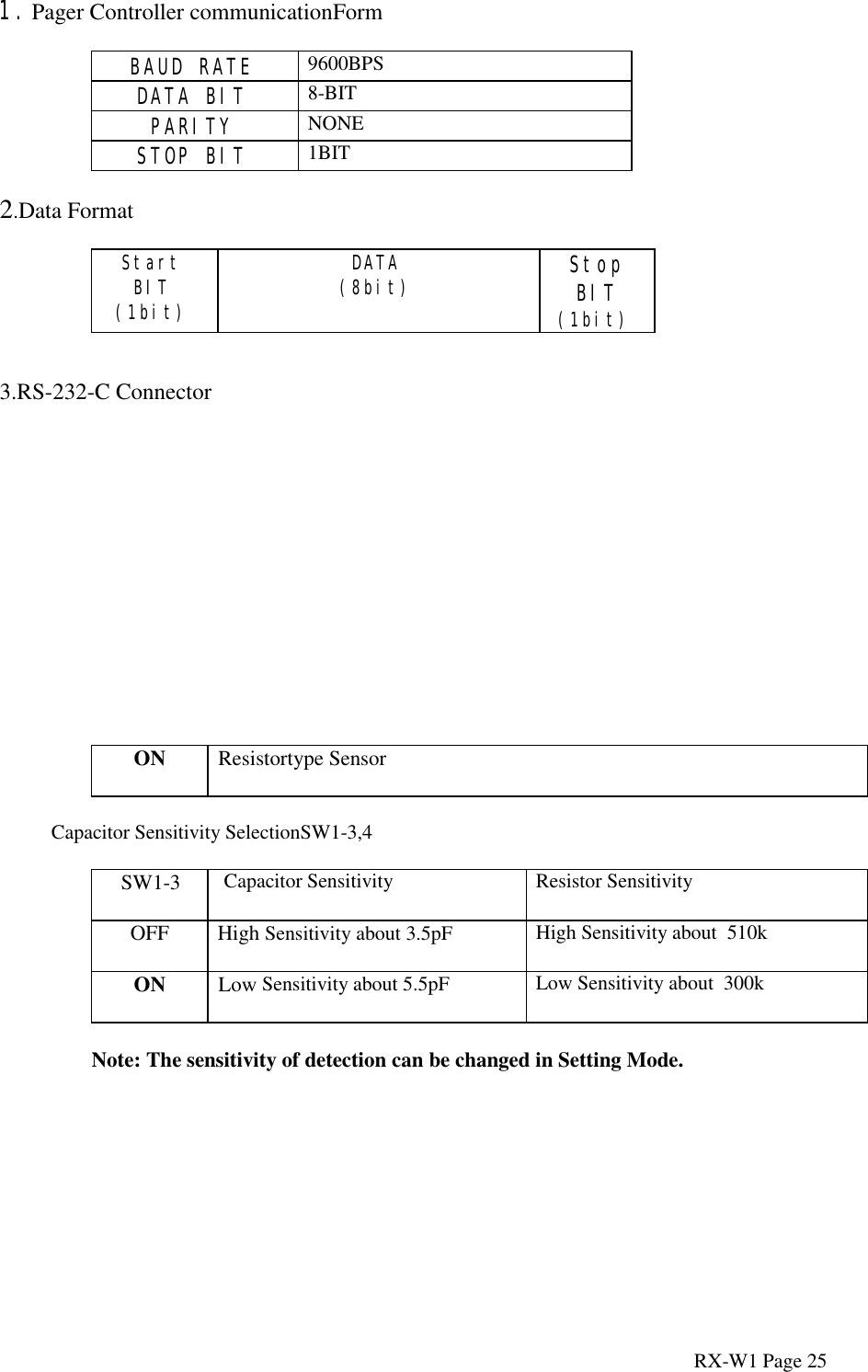
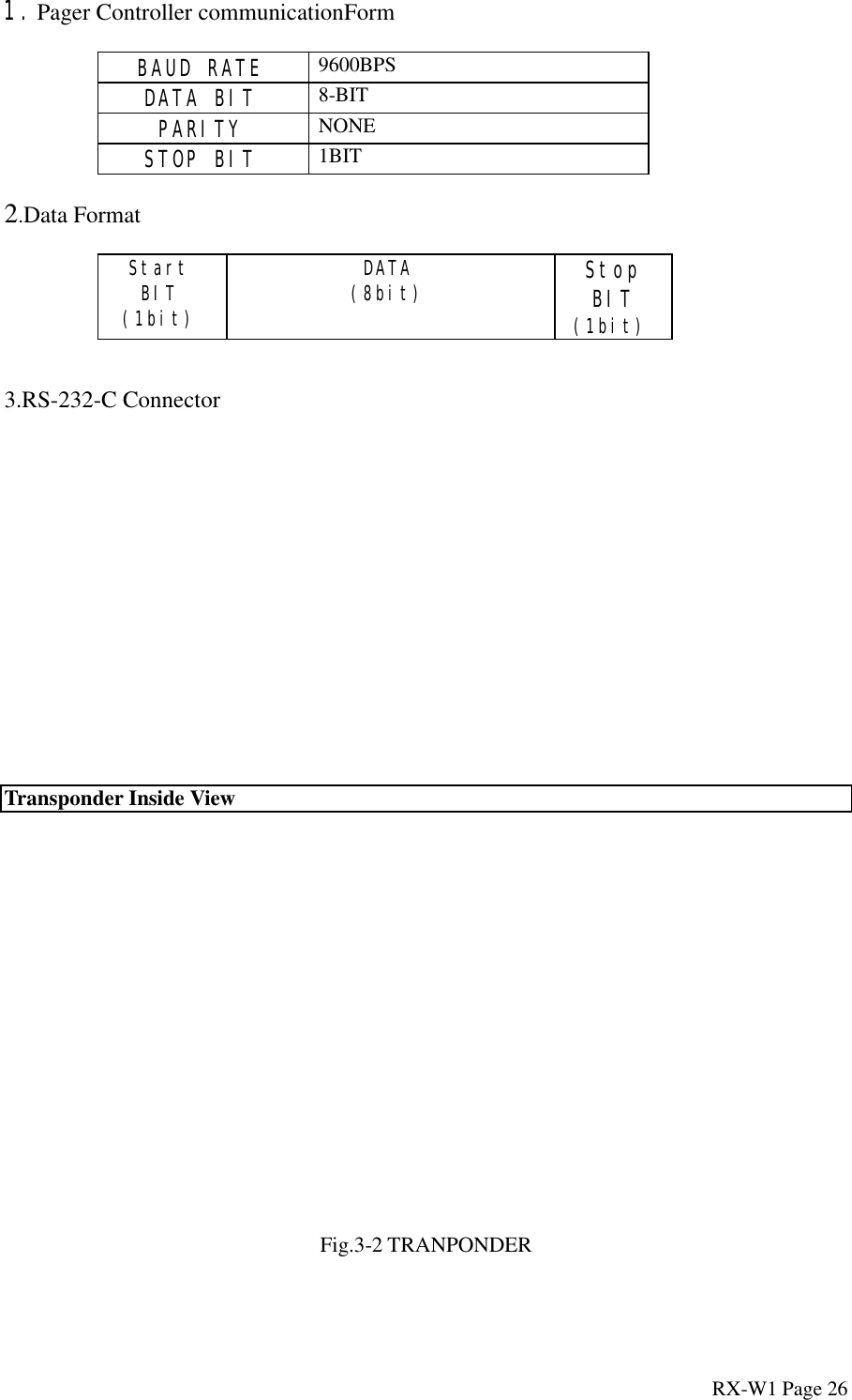
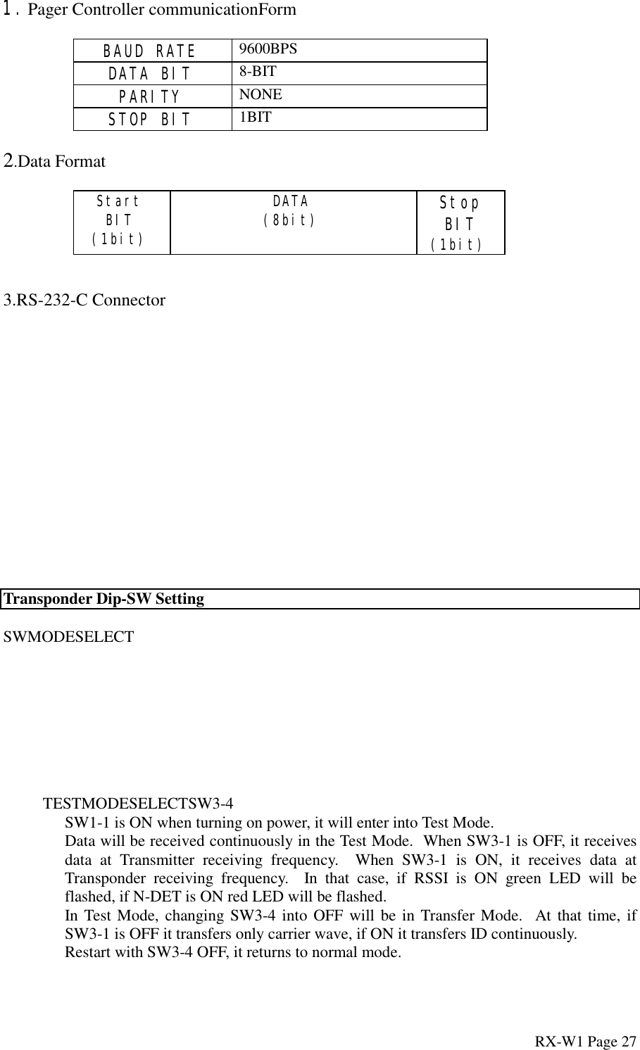
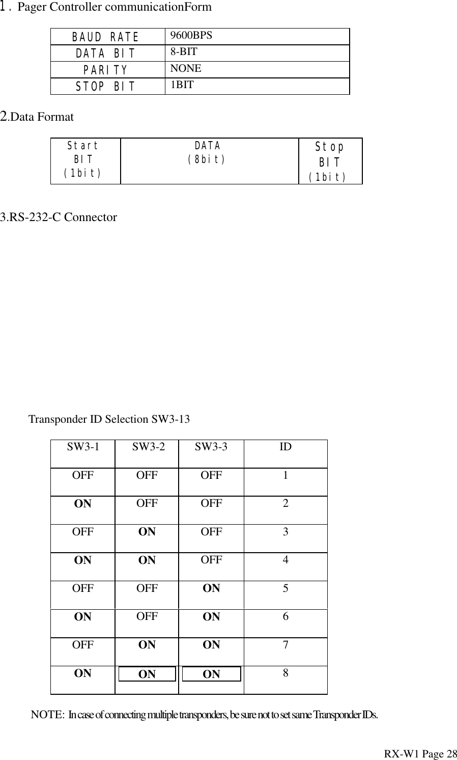
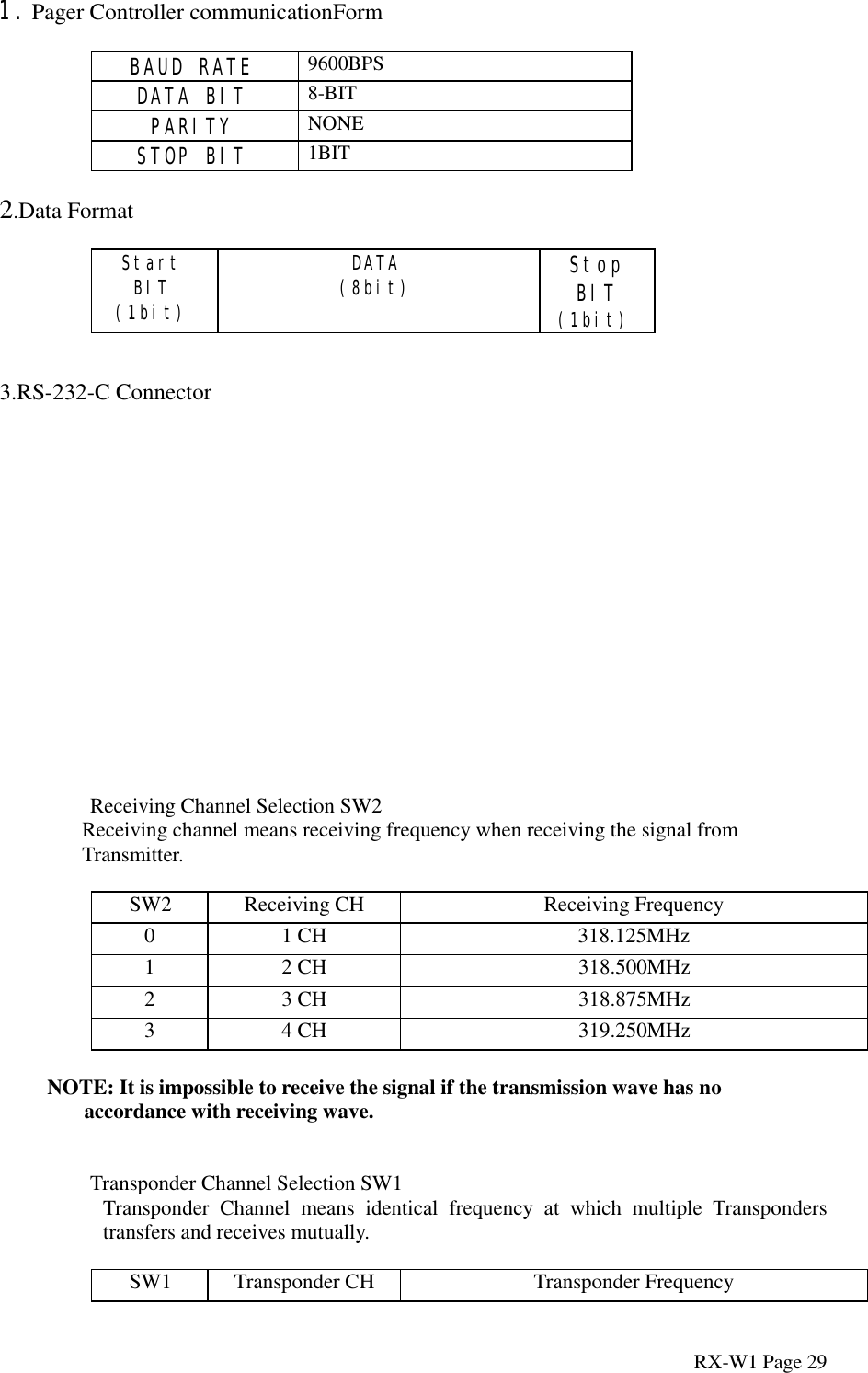
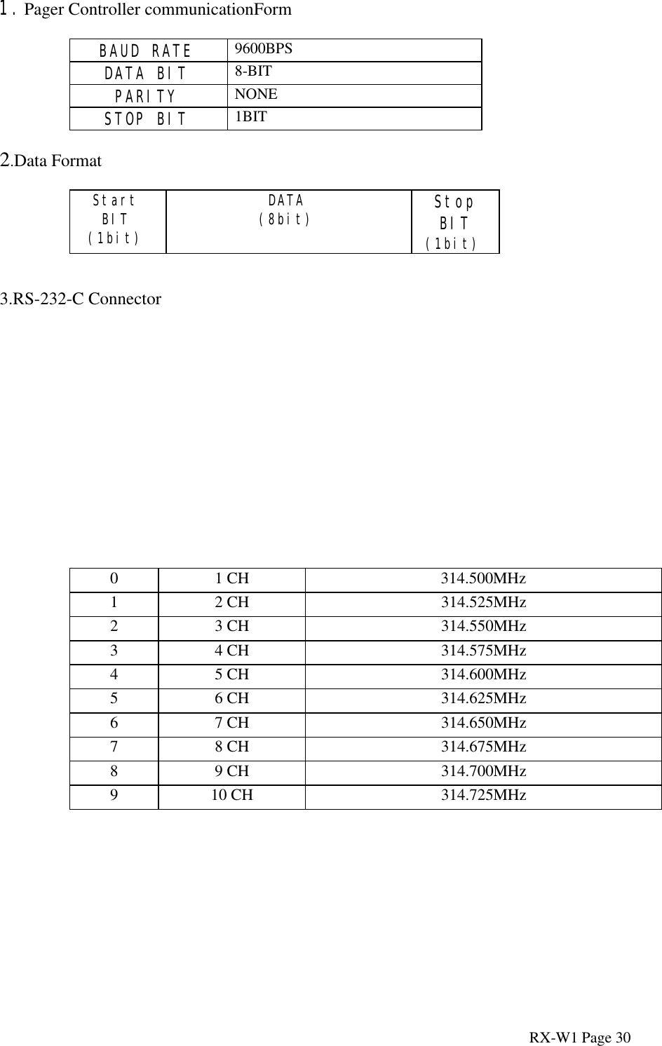
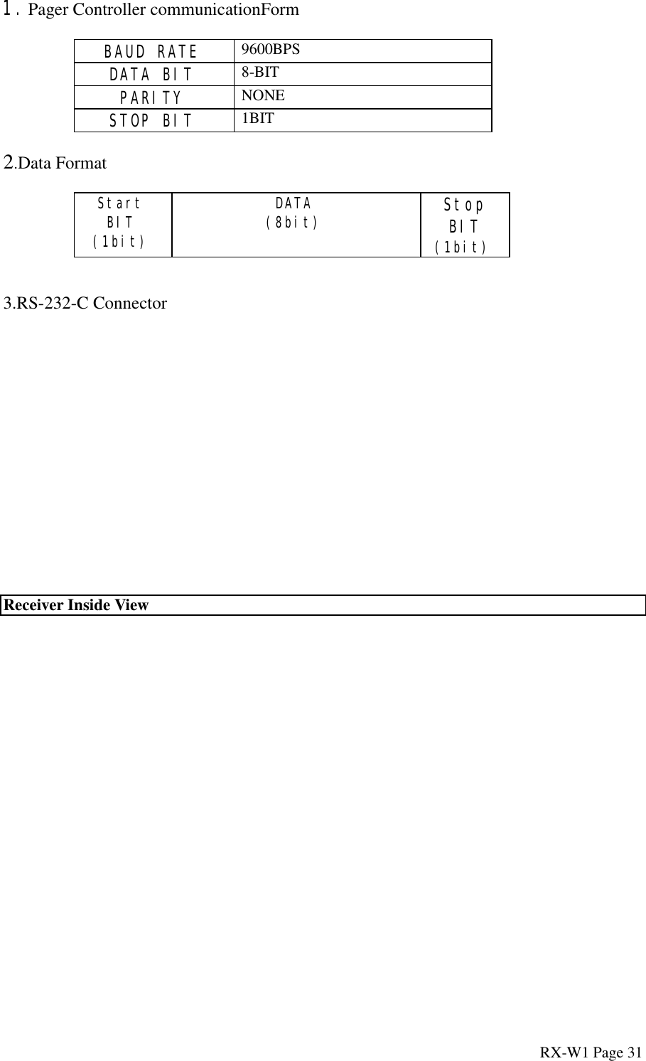
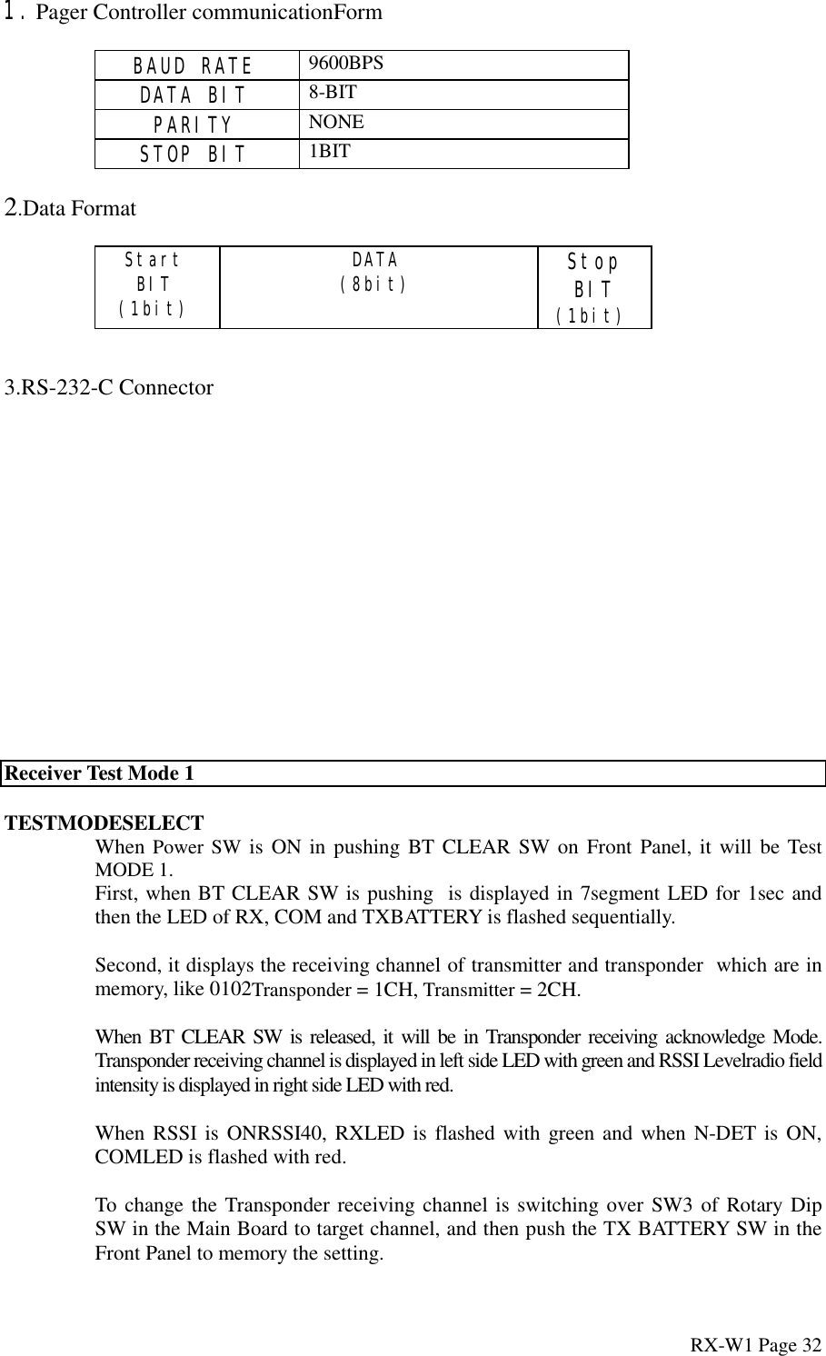
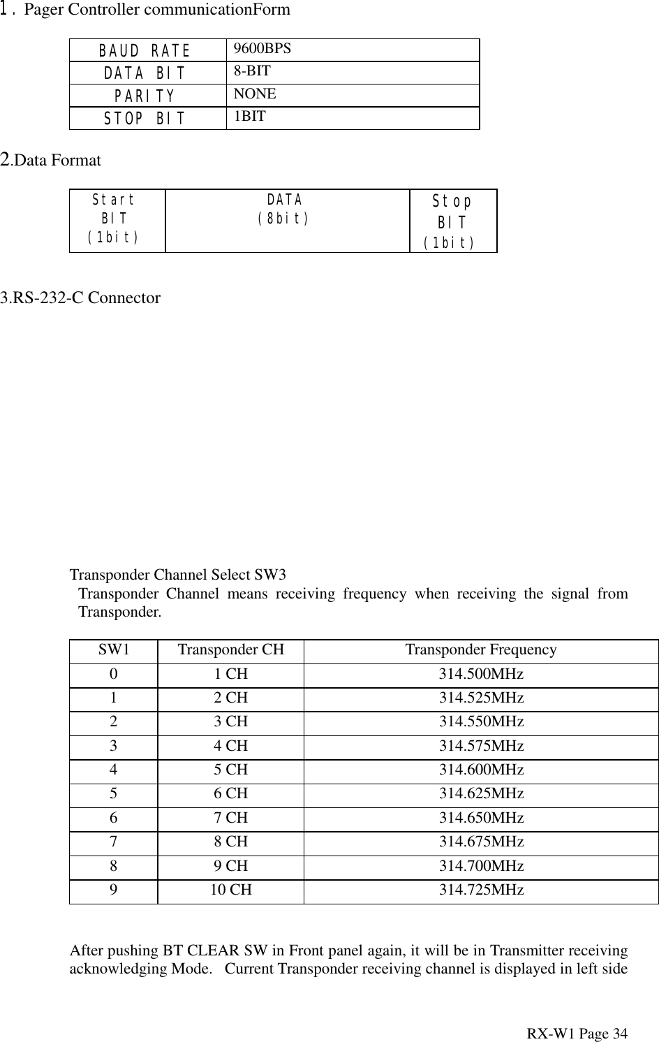
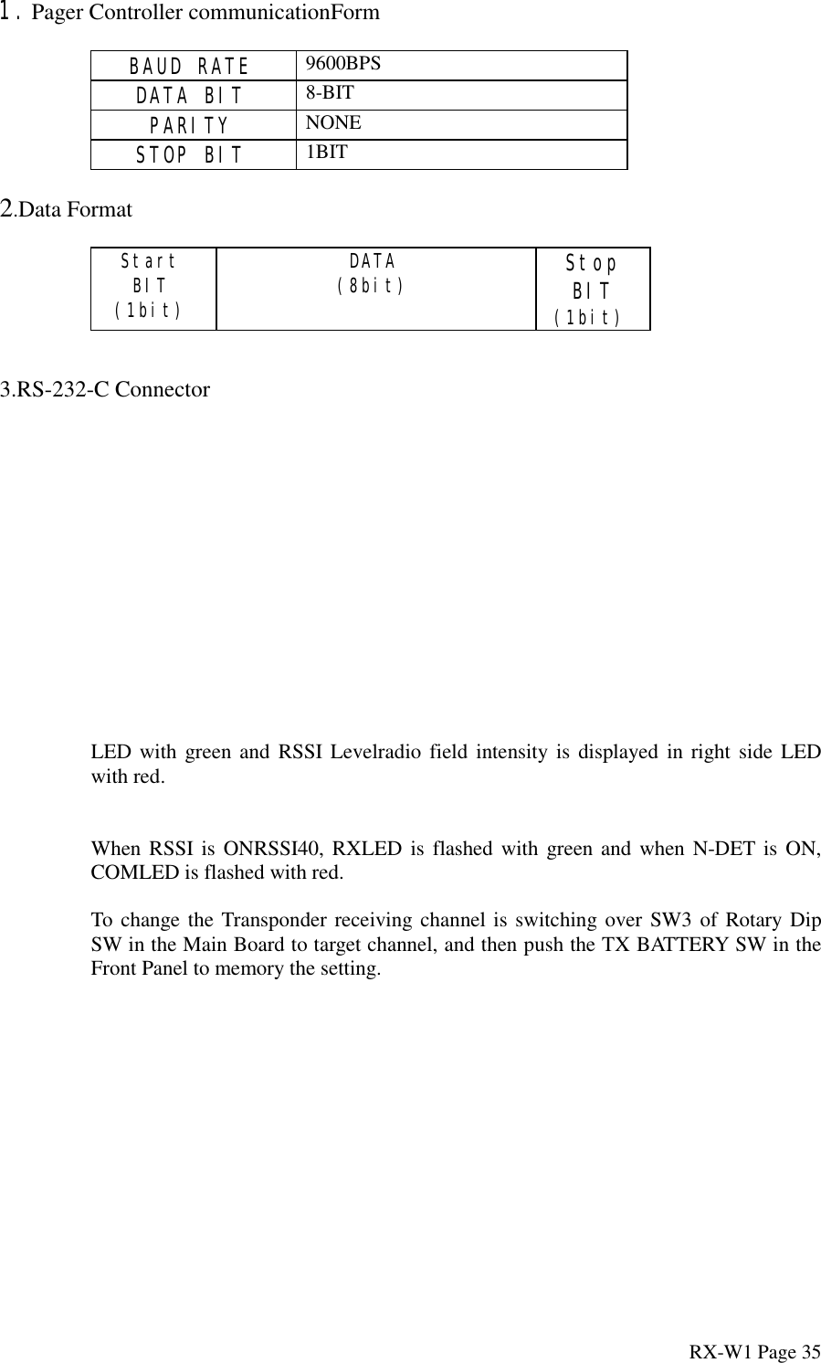
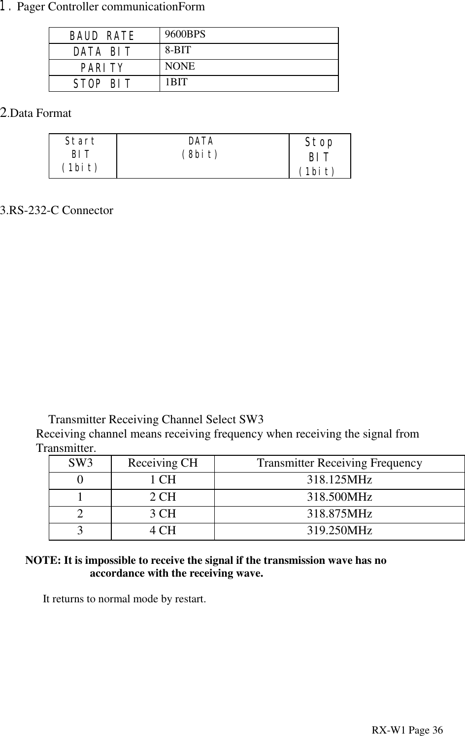
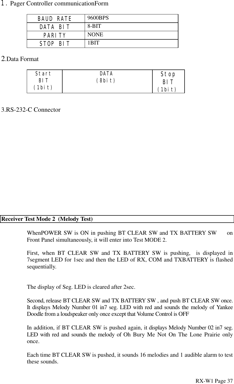
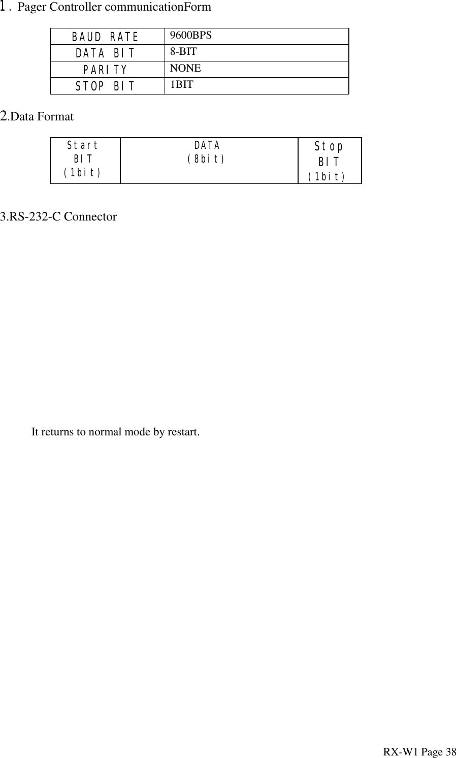
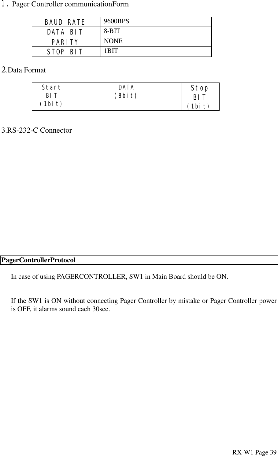
![1. Pager Controller communicationFormBAUD RATE 9600BPSDATA BIT 8-BITPARITY NONESTOP BIT 1BIT2.Data FormatStartBIT(1bit)DATA(8bit) StopBIT(1bit)3.RS-232-C ConnectorRX-W1 Page 8[1] Wetness Sensing System(1) Overview](https://usermanual.wiki/TAKAYA/RP69W01.Reply-to-Reference-Number-7066/User-Guide-31833-Page-8.png)