TAKAYA RP69W01 User Manual Reply to Reference Number 7066
TAKAYA Corporation Reply to Reference Number 7066
TAKAYA >
Contents
- 1. Operating Manual
- 2. Manual ClassB declaration
- 3. Correspondence Reference Number 7066
- 4. Reply to Reference Number 7066
Reply to Reference Number 7066

1. Pager Controller communicationForm
BAUD RATE 9600BPS
DATA BIT 8-BIT
PARITY NONE
STOP BIT 1BIT
2.Data Format
Start
BIT
(1bit)
DATA
(8bit) Stop
BIT
(1bit)
3.RS-232-C Connector
RX-W1 Page 1
OPERATION
MANUAL
New Wetness Sensing System RX69W1
For monitoring purpose in USA

1. Pager Controller communicationForm
BAUD RATE 9600BPS
DATA BIT 8-BIT
PARITY NONE
STOP BIT 1BIT
2.Data Format
Start
BIT
(1bit)
DATA
(8bit) Stop
BIT
(1bit)
3.RS-232-C Connector
RX-W1 Page 2

1. Pager Controller communicationForm
BAUD RATE 9600BPS
DATA BIT 8-BIT
PARITY NONE
STOP BIT 1BIT
2.Data Format
Start
BIT
(1bit)
DATA
(8bit) Stop
BIT
(1bit)
3.RS-232-C Connector
RX-W1 Page 3
By Nippon Kodoshi Corporation
September 4,1998

1. Pager Controller communicationForm
BAUD RATE 9600BPS
DATA BIT 8-BIT
PARITY NONE
STOP BIT 1BIT
2.Data Format
Start
BIT
(1bit)
DATA
(8bit) Stop
BIT
(1bit)
3.RS-232-C Connector
RX-W1 Page 4
Table of Contents
DESCRIPTION
3
OverView 4
Specifications 5
Location and Function of Controls
Transmitter Introduction 6
SensorIntroduction 7
Transmitter and Sensor Operating 8
Sensor Installation to a disposal diaper 9
Transponder Introduction 10
Receiver Introduction 11
Receiver Operating 13
Inside Views, Dip-SW Setting 14
Transmitter Inside View 14

1. Pager Controller communicationForm
BAUD RATE 9600BPS
DATA BIT 8-BIT
PARITY NONE
STOP BIT 1BIT
2.Data Format
Start
BIT
(1bit)
DATA
(8bit) Stop
BIT
(1bit)
3.RS-232-C Connector
RX-W1 Page 5
TransmitterDip-SWSetting 15
Transponder Inside View 16
Transponder Dip-SW Setting 17
Receiver Inside View 19
Receiver Test Mode 1 20
Receiver Test Mode 2 (Melody) 23
PagerControllerProtocol 24
loneode 26
Transmitter Clone Mode 26
Transponder Clone Mode 31
Receiver Clone Mode 33

1. Pager Controller communicationForm
BAUD RATE 9600BPS
DATA BIT 8-BIT
PARITY NONE
STOP BIT 1BIT
2.Data Format
Start
BIT
(1bit)
DATA
(8bit) Stop
BIT
(1bit)
3.RS-232-C Connector
RX-W1 Page 6
FCC PART 15 CLASS B MANUAL
DESCRIPTION
NOTICE
This equipment has been tested and found to comply with the limits for a Class B digital device,
pursuant to Part 15 of the FCC Rules. These limits are designed to provide reasonable protection
against harmful interference in a residential installation.
This equipment generates, uses and can radiate radio frequency energy and, if not installed and
used in accordance with the instruction, may cause harmful interference to radio communications.
However, there is no guarantee that interference will not occur in a particular installation. If this
equipment does cause harmful interference to radio or television reception, which can be
determined by turning the equipment off and on, the user is encouraged to try to correct the
interference by one or more of the following measures:
-Reorient or relocate the receiving antenna
-Increase the separation between the equipment and receiver.
-Connect the equipment into an outlet on a circuit different from that to which the receiver is

1. Pager Controller communicationForm
BAUD RATE 9600BPS
DATA BIT 8-BIT
PARITY NONE
STOP BIT 1BIT
2.Data Format
Start
BIT
(1bit)
DATA
(8bit) Stop
BIT
(1bit)
3.RS-232-C Connector
RX-W1 Page 7
connected.
-Consult the dealer or an experienced radio/TV technician for help.
FCC WARNING
Changes or modifications not expressly approved by the party responsible for compliance could
void the user’s authority to operate the equipment.
The device is complies with part 15 of the FCC rules.
Operation is subject to the conditions that this device
does not cause harmful interference.
This device complies with part 15 of the FCC Rules.
Operation is subject to the following two conditions:
(1) This device may not cause harmful interference, and
(2) this device must accept any interference received,
including interference that may cause undesired operation.

1. Pager Controller communicationForm
BAUD RATE 9600BPS
DATA BIT 8-BIT
PARITY NONE
STOP BIT 1BIT
2.Data Format
Start
BIT
(1bit)
DATA
(8bit) Stop
BIT
(1bit)
3.RS-232-C Connector
RX-W1 Page 8
[1] Wetness Sensing System
(1) Overview
1. Pager Controller communicationForm
BAUD RATE 9600BPS
DATA BIT 8-BIT
PARITY NONE
STOP BIT 1BIT
2.Data Format
Start
BIT
(1bit)
DATA
(8bit) Stop
BIT
(1bit)
3.RS-232-C Connector
RX-W1 Page 9
’†Œp‹@
ŒÅ’èŒ^ŽóM‹@
Œg‘ÑŒ^•\ Ž¦‹@
‘—M‹@
—¾•êŽº
‹Žº

1. Pager Controller communicationForm
BAUD RATE 9600BPS
DATA BIT 8-BIT
PARITY NONE
STOP BIT 1BIT
2.Data Format
Start
BIT
(1bit)
DATA
(8bit) Stop
BIT
(1bit)
3.RS-232-C Connector
RX-W1 Page 10
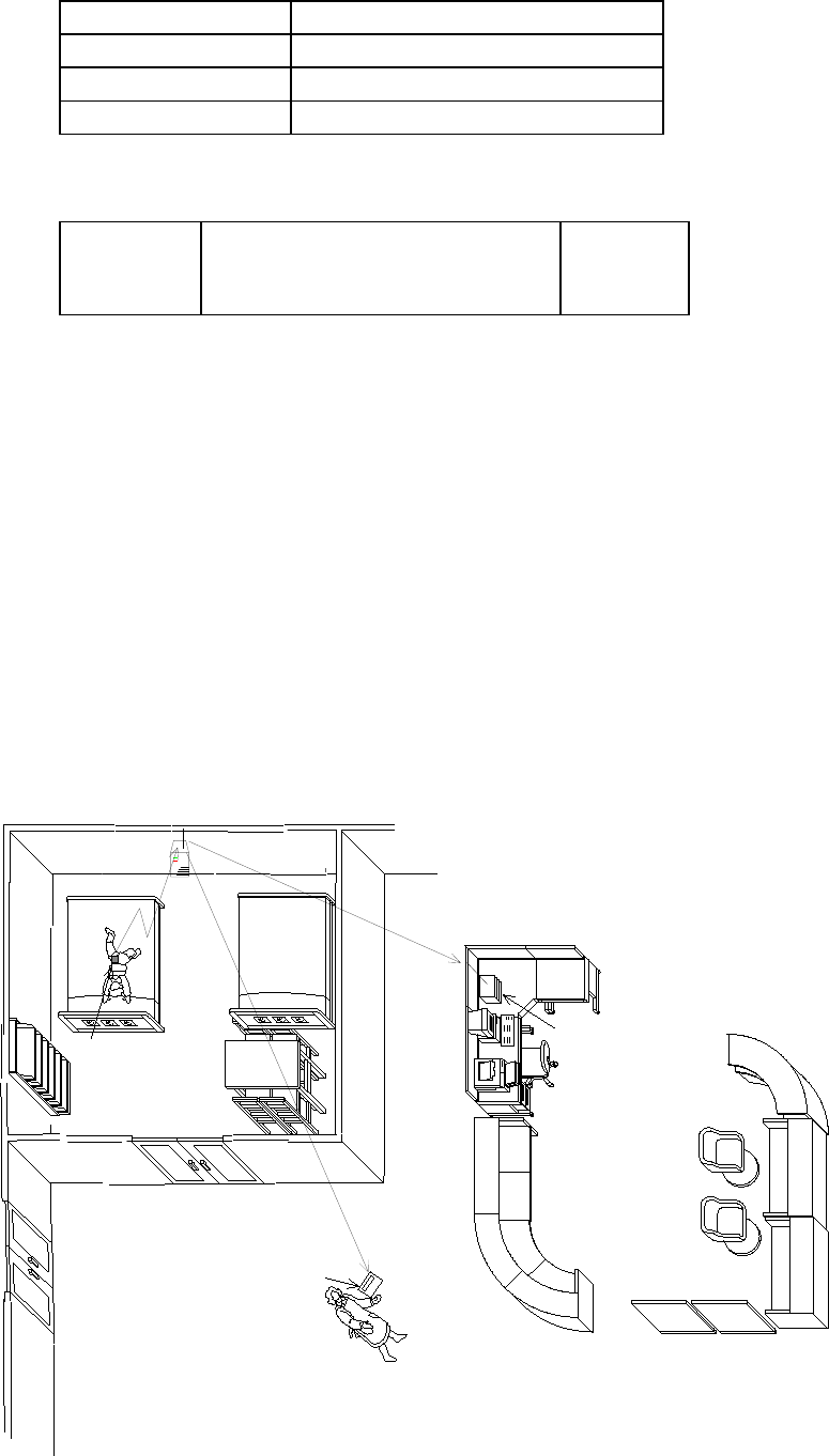
This Wetness Sensing System is comprised with transmitters, transponders and
receivers, which inform caregivers of sensing moisture in a diaper. Once wetness sensor
incorporated into diaper is aware of moisture, the transmitter including sensor puts out
the signal to the transponder and then to the receiver.

1. Pager Controller communicationForm
BAUD RATE 9600BPS
DATA BIT 8-BIT
PARITY NONE
STOP BIT 1BIT
2.Data Format
Start
BIT
(1bit)
DATA
(8bit) Stop
BIT
(1bit)
3.RS-232-C Connector
RX-W1 Page 11
Specifications
TRANSMITTER
Frequency 318.125M, 318.500M, 318.875M, 319.250MHz
RF Output Power 2400V/m (67.6dBm) at 3 m
Frequency stability 0.001
Identification Area ID199, Individual ID 199
Modulation system Variable reactance frequency modulation
Maximum Deviation 4 kHz
Power Source 3V (lithium battery CR2032)
Battery Life about 3 months ( dropped to 2.5V)
TRANSPONDER
Receive system Double-conversion superheterodyne
Receiving Frequency 1 318.125M, 318.500M, 318.875M, 319.250MHz
Receiving Frequency 2 314.500M~314.725MHz(25kHz step)
Sensitivity -113dBm for 12dB SINAD
Intermediate frequencies 1st 21.7MHz
2nd 450kHz

1. Pager Controller communicationForm
BAUD RATE 9600BPS
DATA BIT 8-BIT
PARITY NONE
STOP BIT 1BIT
2.Data Format
Start
BIT
(1bit)
DATA
(8bit) Stop
BIT
(1bit)
3.RS-232-C Connector
RX-W1 Page 12
Transmitting Frequency 314.500M~314.725MHz(25kHz step)
RF output power 2250V/m ( at 3 m )
Frequency stability 0.001
Modulation system Variable reactance frequency modulation
Maximum Deviation 4 kHz
Power supply requirement DC,AC9V 0.1A AC adaptor
Battery Life about 12 hours
RECEIVER
Receive system Double-conversion superheterodyne
Receiving Frequency 1 318.125M, 318.500M, 318.875M, 319.250MHz
Receiving Frequency 2 314.500M~314.725MHz(25kHz step)
Sensitivity -113dBm for 12dB SINAD
Intermediate frequencies 1st 21.7MHz
2nd 450kHz
Frequency stability 0.001
Power supply requirement DC,AC9V 0.3A AC adaptor
Battery Life about 5 hours

1. Pager Controller communicationForm
BAUD RATE 9600BPS
DATA BIT 8-BIT
PARITY NONE
STOP BIT 1BIT
2.Data Format
Start
BIT
(1bit)
DATA
(8bit) Stop
BIT
(1bit)
3.RS-232-C Connector
RX-W1 Page 13
1. Pager Controller communicationForm
BAUD RATE 9600BPS
DATA BIT 8-BIT
PARITY NONE
STOP BIT 1BIT
2.Data Format
Start
BIT
(1bit)
DATA
(8bit) Stop
BIT
(1bit)
3.RS-232-C Connector
RX-W1 Page 14
Location and Function of Controls
Transmitter Introduction
(1) overview
Sensing devise (sensor) is connected to transmitter. Once sensing devise senses
moisture, transmitter will send signal to transponder.
()Each Designation

1. Pager Controller communicationForm
BAUD RATE 9600BPS
DATA BIT 8-BIT
PARITY NONE
STOP BIT 1BIT
2.Data Format
Start
BIT
(1bit)
DATA
(8bit) Stop
BIT
(1bit)
3.RS-232-C Connector
RX-W1 Page 15
Sensor Introduction

1. Pager Controller communicationForm
BAUD RATE 9600BPS
DATA BIT 8-BIT
PARITY NONE
STOP BIT 1BIT
2.Data Format
Start
BIT
(1bit)
DATA
(8bit) Stop
BIT
(1bit)
3.RS-232-C Connector
RX-W1 Page 16
Transmitter and Sensor Operating
· Open-Close Operation
· Method of Battery desorption and Sensor Attachment

1. Pager Controller communicationForm
BAUD RATE 9600BPS
DATA BIT 8-BIT
PARITY NONE
STOP BIT 1BIT
2.Data Format
Start
BIT
(1bit)
DATA
(8bit) Stop
BIT
(1bit)
3.RS-232-C Connector
RX-W1 Page 17
Sensor Installation to Disposal Diaper
· After attach the sensor, put the cover on a diaper and then fix the transmitter.
Transponder Introduction
Overview
Transponder receives signal from Transmitter and then transmits to Receiver.
It transmits the signal received from Transmitter to another Transponder.

1. Pager Controller communicationForm
BAUD RATE 9600BPS
DATA BIT 8-BIT
PARITY NONE
STOP BIT 1BIT
2.Data Format
Start
BIT
(1bit)
DATA
(8bit) Stop
BIT
(1bit)
3.RS-232-C Connector
RX-W1 Page 18
Each Designation
Directions
The transponder is located in the signal receivable area from Transmitter.

1. Pager Controller communicationForm
BAUD RATE 9600BPS
DATA BIT 8-BIT
PARITY NONE
STOP BIT 1BIT
2.Data Format
Start
BIT
(1bit)
DATA
(8bit) Stop
BIT
(1bit)
3.RS-232-C Connector
RX-W1 Page 19
Receiver Introduction
1. Overview
When the receiver receives signal from the transponder, it informs caregivers of
received signal information (e.g. sense moisture or battery shutoff) by alarm of
melodies and display.
Each Designation

1. Pager Controller communicationForm
BAUD RATE 9600BPS
DATA BIT 8-BIT
PARITY NONE
STOP BIT 1BIT
2.Data Format
Start
BIT
(1bit)
DATA
(8bit) Stop
BIT
(1bit)
3.RS-232-C Connector
RX-W1 Page 20
a.
Display Receiver Battery Shutoff
When the battery of receiver run down, LED will
flash.
Information Display
When receiving the signal of sensing moisture in a
diaper, it displays Area ID in right two-digit and
transmitter ID in left two-digit. (NOTE: In case of sensing
multiple IDs, it displays those IDs in turn.)
(Example of Display 1)
Example of Display 2
When flashing “Warning LED for Battery Shutoff”, push “Acknowledge
button for Transmitter Battery Shutoff”, is displayed.

1. Pager Controller communicationForm
BAUD RATE 9600BPS
DATA BIT 8-BIT
PARITY NONE
STOP BIT 1BIT
2.Data Format
Start
BIT
(1bit)
DATA
(8bit) Stop
BIT
(1bit)
3.RS-232-C Connector
RX-W1 Page 21
7Receiver Operation
Turning on power, current receiving channel for the transmitter is displayed in 7 segment
Display with red LED and current receiving channel for the transponder in 7 segment display
with green LED, like for 5sec, after that it will clear the ID.
When the transmitter senses moisture in a diaper, the receiver displays Area ID and
Transmitter ID and puts melodies on.
Once Transmitter IDs are received, it continues displaying these IDs till the signal from the
transmitter is cut off for 30sec. Those IDs will be cleared automatically when the signal is
aborted (i.e. it displays those IDs till the diaper attached the sensor is changed.).
Volume Control SW

1. Pager Controller communicationForm
BAUD RATE 9600BPS
DATA BIT 8-BIT
PARITY NONE
STOP BIT 1BIT
2.Data Format
Start
BIT
(1bit)
DATA
(8bit) Stop
BIT
(1bit)
3.RS-232-C Connector
RX-W1 Page 22
It changes Volume of melodies as four stage (large, middle, small and OFF).
TXBATTERYSWLED
Square red LED flashes in Transmitter Battery Shutoff.
Transmitter ID which runs out is displayed during pushing this SW. (In case of
detecting multiple IDs, it displays those IDs in turn.)
BT CLEAR SW
Battery Shutoff LED will be lighted out and its IDs will be cleared after checking which ID is
detected by pushing TX Battery SW and changing the battery.
NOTE: Be sure to clear detected IDs after changing the battery
Power Supply
AC adapter more than 0.3A, 9V(DC, AC) is available.
In electricity failure, this system can work about for 5 hours by using built-in rechargeable
battery.
1. Pager Controller communicationForm
BAUD RATE 9600BPS
DATA BIT 8-BIT
PARITY NONE
STOP BIT 1BIT
2.Data Format
Start
BIT
(1bit)
DATA
(8bit) Stop
BIT
(1bit)
3.RS-232-C Connector
RX-W1 Page 23
3Inside Views, Dip-SW Setting
Transmitter Inside View
Fig.3-1 TRANSMITTER
1. Pager Controller communicationForm
BAUD RATE 9600BPS
DATA BIT 8-BIT
PARITY NONE
STOP BIT 1BIT
2.Data Format
Start
BIT
(1bit)
DATA
(8bit) Stop
BIT
(1bit)
3.RS-232-C Connector
RX-W1 Page 24
Transmitter Dip-SW Setting
SW1MODESELECT
TESTMODESELECTIONSW1-1
SW1-1 is ON when turning on power, it will enter into Test Mode.
It will be transfered data continuously in the Test Mode. To stop the continuous transfer
is turning SW1-1 off in Test Mode.
Turning on power again with SW1-1 OF enters into Normal Mode.
Sensitivity LIMIT Setting MODE (SW1-4 ON,SW1-1 ON)
To change the sensitivity of detection is switching both of SW1-4 and SW1-1 to the on
position.
SENSOR TYPE SELECTIONSW1-2
SW1-2 SENSOR TYPE
OFF Capacitortype Sensor

1. Pager Controller communicationForm
BAUD RATE 9600BPS
DATA BIT 8-BIT
PARITY NONE
STOP BIT 1BIT
2.Data Format
Start
BIT
(1bit)
DATA
(8bit) Stop
BIT
(1bit)
3.RS-232-C Connector
RX-W1 Page 25
ON Resistortype Sensor
Capacitor Sensitivity SelectionSW1-3,4
SW1-3 Capacitor Sensitivity Resistor Sensitivity
OFF High Sensitivity about 3.5pF High Sensitivity about 510k
ON Low Sensitivity about 5.5pF Low Sensitivity about 300k
Note: The sensitivity of detection can be changed in Setting Mode.

1. Pager Controller communicationForm
BAUD RATE 9600BPS
DATA BIT 8-BIT
PARITY NONE
STOP BIT 1BIT
2.Data Format
Start
BIT
(1bit)
DATA
(8bit) Stop
BIT
(1bit)
3.RS-232-C Connector
RX-W1 Page 26
Transponder Inside View
Fig.3-2 TRANPONDER

1. Pager Controller communicationForm
BAUD RATE 9600BPS
DATA BIT 8-BIT
PARITY NONE
STOP BIT 1BIT
2.Data Format
Start
BIT
(1bit)
DATA
(8bit) Stop
BIT
(1bit)
3.RS-232-C Connector
RX-W1 Page 27
Transponder Dip-SW Setting
SWMODESELECT
TESTMODESELECTSW3-4
SW1-1 is ON when turning on power, it will enter into Test Mode.
Data will be received continuously in the Test Mode. When SW3-1 is OFF, it receives
data at Transmitter receiving frequency. When SW3-1 is ON, it receives data at
Transponder receiving frequency. In that case, if RSSI is ON green LED will be
flashed, if N-DET is ON red LED will be flashed.
In Test Mode, changing SW3-4 into OFF will be in Transfer Mode. At that time, if
SW3-1 is OFF it transfers only carrier wave, if ON it transfers ID continuously.
Restart with SW3-4 OFF, it returns to normal mode.

1. Pager Controller communicationForm
BAUD RATE 9600BPS
DATA BIT 8-BIT
PARITY NONE
STOP BIT 1BIT
2.Data Format
Start
BIT
(1bit)
DATA
(8bit) Stop
BIT
(1bit)
3.RS-232-C Connector
RX-W1 Page 28
Transponder ID Selection SW3-13
SW3-1 SW3-2 SW3-3 ID
OFF OFF OFF 1
ON OFF OFF 2
OFF ON OFF 3
ON ON OFF 4
OFF OFF ON 5
ON OFF ON 6
OFF ON ON 7
ON ON ON 8
NOTE: In case of connecting multiple transponders, be sure not to set same Transponder IDs.

1. Pager Controller communicationForm
BAUD RATE 9600BPS
DATA BIT 8-BIT
PARITY NONE
STOP BIT 1BIT
2.Data Format
Start
BIT
(1bit)
DATA
(8bit) Stop
BIT
(1bit)
3.RS-232-C Connector
RX-W1 Page 29
Receiving Channel Selection SW2
Receiving channel means receiving frequency when receiving the signal from
Transmitter.
SW2 Receiving CH Receiving Frequency
0 1 CH 318.125MHz
1 2 CH 318.500MHz
2 3 CH 318.875MHz
3 4 CH 319.250MHz
NOTE: It is impossible to receive the signal if the transmission wave has no
accordance with receiving wave.
Transponder Channel Selection SW1
Transponder Channel means identical frequency at which multiple Transponders
transfers and receives mutually.
SW1 Transponder CH Transponder Frequency

1. Pager Controller communicationForm
BAUD RATE 9600BPS
DATA BIT 8-BIT
PARITY NONE
STOP BIT 1BIT
2.Data Format
Start
BIT
(1bit)
DATA
(8bit) Stop
BIT
(1bit)
3.RS-232-C Connector
RX-W1 Page 30
0 1 CH 314.500MHz
1 2 CH 314.525MHz
2 3 CH 314.550MHz
3 4 CH 314.575MHz
4 5 CH 314.600MHz
5 6 CH 314.625MHz
6 7 CH 314.650MHz
7 8 CH 314.675MHz
8 9 CH 314.700MHz
9 10 CH 314.725MHz

1. Pager Controller communicationForm
BAUD RATE 9600BPS
DATA BIT 8-BIT
PARITY NONE
STOP BIT 1BIT
2.Data Format
Start
BIT
(1bit)
DATA
(8bit) Stop
BIT
(1bit)
3.RS-232-C Connector
RX-W1 Page 31
Receiver Inside View

1. Pager Controller communicationForm
BAUD RATE 9600BPS
DATA BIT 8-BIT
PARITY NONE
STOP BIT 1BIT
2.Data Format
Start
BIT
(1bit)
DATA
(8bit) Stop
BIT
(1bit)
3.RS-232-C Connector
RX-W1 Page 32
Receiver Test Mode 1
TESTMODESELECT
When Power SW is ON in pushing BT CLEAR SW on Front Panel, it will be Test
MODE 1.
First, when BT CLEAR SW is pushing is displayed in 7segment LED for 1sec and
then the LED of RX, COM and TXBATTERY is flashed sequentially.
Second, it displays the receiving channel of transmitter and transponder which are in
memory, like 0102Transponder = 1CH, Transmitter = 2CH.
When BT CLEAR SW is released, it will be in Transponder receiving acknowledge Mode.
Transponder receiving channel is displayed in left side LED with green and RSSI Levelradio field
intensity is displayed in right side LED with red.
When RSSI is ONRSSI40, RXLED is flashed with green and when N-DET is ON,
COMLED is flashed with red.
To change the Transponder receiving channel is switching over SW3 of Rotary Dip
SW in the Main Board to target channel, and then push the TX BATTERY SW in the
Front Panel to memory the setting.

1. Pager Controller communicationForm
BAUD RATE 9600BPS
DATA BIT 8-BIT
PARITY NONE
STOP BIT 1BIT
2.Data Format
Start
BIT
(1bit)
DATA
(8bit) Stop
BIT
(1bit)
3.RS-232-C Connector
RX-W1 Page 33

1. Pager Controller communicationForm
BAUD RATE 9600BPS
DATA BIT 8-BIT
PARITY NONE
STOP BIT 1BIT
2.Data Format
Start
BIT
(1bit)
DATA
(8bit) Stop
BIT
(1bit)
3.RS-232-C Connector
RX-W1 Page 34
Transponder Channel Select SW3
Transponder Channel means receiving frequency when receiving the signal from
Transponder.
SW1 Transponder CH Transponder Frequency
0 1 CH 314.500MHz
1 2 CH 314.525MHz
2 3 CH 314.550MHz
3 4 CH 314.575MHz
4 5 CH 314.600MHz
5 6 CH 314.625MHz
6 7 CH 314.650MHz
7 8 CH 314.675MHz
8 9 CH 314.700MHz
9 10 CH 314.725MHz
After pushing BT CLEAR SW in Front panel again, it will be in Transmitter receiving
acknowledging Mode. Current Transponder receiving channel is displayed in left side

1. Pager Controller communicationForm
BAUD RATE 9600BPS
DATA BIT 8-BIT
PARITY NONE
STOP BIT 1BIT
2.Data Format
Start
BIT
(1bit)
DATA
(8bit) Stop
BIT
(1bit)
3.RS-232-C Connector
RX-W1 Page 35
LED with green and RSSI Levelradio field intensity is displayed in right side LED
with red.
When RSSI is ONRSSI40, RXLED is flashed with green and when N-DET is ON,
COMLED is flashed with red.
To change the Transponder receiving channel is switching over SW3 of Rotary Dip
SW in the Main Board to target channel, and then push the TX BATTERY SW in the
Front Panel to memory the setting.

1. Pager Controller communicationForm
BAUD RATE 9600BPS
DATA BIT 8-BIT
PARITY NONE
STOP BIT 1BIT
2.Data Format
Start
BIT
(1bit)
DATA
(8bit) Stop
BIT
(1bit)
3.RS-232-C Connector
RX-W1 Page 36
Transmitter Receiving Channel Select SW3
Receiving channel means receiving frequency when receiving the signal from
Transmitter.
SW3 Receiving CH Transmitter Receiving Frequency
0 1 CH 318.125MHz
1 2 CH 318.500MHz
2 3 CH 318.875MHz
3 4 CH 319.250MHz
NOTE: It is impossible to receive the signal if the transmission wave has no
accordance with the receiving wave.
It returns to normal mode by restart.
1. Pager Controller communicationForm
BAUD RATE 9600BPS
DATA BIT 8-BIT
PARITY NONE
STOP BIT 1BIT
2.Data Format
Start
BIT
(1bit)
DATA
(8bit) Stop
BIT
(1bit)
3.RS-232-C Connector
RX-W1 Page 37
Receiver Test Mode 2 (Melody Test)
WhenPOWER SW is ON in pushing BT CLEAR SW and TX BATTERY SW on
Front Panel simultaneously, it will enter into Test MODE 2.
First, when BT CLEAR SW and TX BATTERY SW is pushing, is displayed in
7segment LED for 1sec and then the LED of RX, COM and TXBATTERY is flashed
sequentially.
The display of Seg. LED is cleared after 2sec.
Second, release BT CLEAR SW and TX BATTERY SW , and push BT CLEAR SW once.
It displays Melody Number 01 in7 seg. LED with red and sounds the melody of Yankee
Doodle from a loudspeaker only once except that Volume Control is OFF
In addition, if BT CLEAR SW is pushed again, it displays Melody Number 02 in7 seg.
LED with red and sounds the melody of Oh Bury Me Not On The Lone Prairie only
once.
Each time BT CLEAR SW is pushed, it sounds 16 melodies and 1 audible alarm to test
these sounds.

1. Pager Controller communicationForm
BAUD RATE 9600BPS
DATA BIT 8-BIT
PARITY NONE
STOP BIT 1BIT
2.Data Format
Start
BIT
(1bit)
DATA
(8bit) Stop
BIT
(1bit)
3.RS-232-C Connector
RX-W1 Page 38
It returns to normal mode by restart.

1. Pager Controller communicationForm
BAUD RATE 9600BPS
DATA BIT 8-BIT
PARITY NONE
STOP BIT 1BIT
2.Data Format
Start
BIT
(1bit)
DATA
(8bit) Stop
BIT
(1bit)
3.RS-232-C Connector
RX-W1 Page 39
PagerControllerProtocol
In case of using PAGERCONTROLLER, SW1 in Main Board should be ON.
If the SW1 is ON without connecting Pager Controller by mistake or Pager Controller power
is OFF, it alarms sound each 30sec.