Contents
Operating Manual

RX-W1 Page 1
OPERATION
MANUAL
New Wetness Sensing System RX69W1
For monitoring purpose in USA
By Nippon Kodoshi Corporation
September 4,1998

RX-W1 Page 2
Table of Contents
DESCRIPTION 3
OverView 4
Specifications 5
Location and Function of Controls
Transmitter Introduction 6
SensorIntroduction 7
Transmitter and Sensor Operating 8
Sensor Installation to a disposal diaper 9
Transponder Introduction 10
Receiver Introduction 11
Receiver Operating 13
Inside Views, Dip-SW Setting 14
Transmitter Inside View 14
TransmitterDip-SWSetting 15
Transponder Inside View 16
Transponder Dip-SW Setting 17
Receiver Inside View 19
Receiver Test Mode 1 20
Receiver Test Mode 2 (Melody) 23
PagerControllerProtocol 24
loneode 26
Transmitter Clone Mode 26
Transponder Clone Mode 31
Receiver Clone Mode 33

RX-W1 Page 3
FCC PART 15 CLASS B MANUAL
DESCRIPTION
NOTICE
This equipment has been tested and found to comply with the limits for a Class B digital
device, pursuant to Part 15 of the FCC Rules. These limits are designed to provide
reasonable protection against harmful interference in a residential installation.
This equipment generates, uses and can radiate radio frequency energy and, if not
installed and used in accordance with the instruction, may cause harmful interference to
radio communications. However, there is no guarantee that interference will not occur
in a particular installation. If this equipment does cause harmful interference to radio
or television reception, which can be determined by turning the equipment off and on,
the user is encouraged to try to correct the interference by one or more of the following
measures:
-Reorient or relocate the receiving antenna
-Increase the separation between the equipment and receiver.
-Connect the equipment into an outlet on a circuit different from that to which the
receiver is connected.
-Consult the dealer or an experienced radio/TV technician for help.
FCC WARNING
Changes or modifications not expressly approved by the party responsible for compliance
could void the user’s authority to operate the equipment.
RX-W1 Page 4
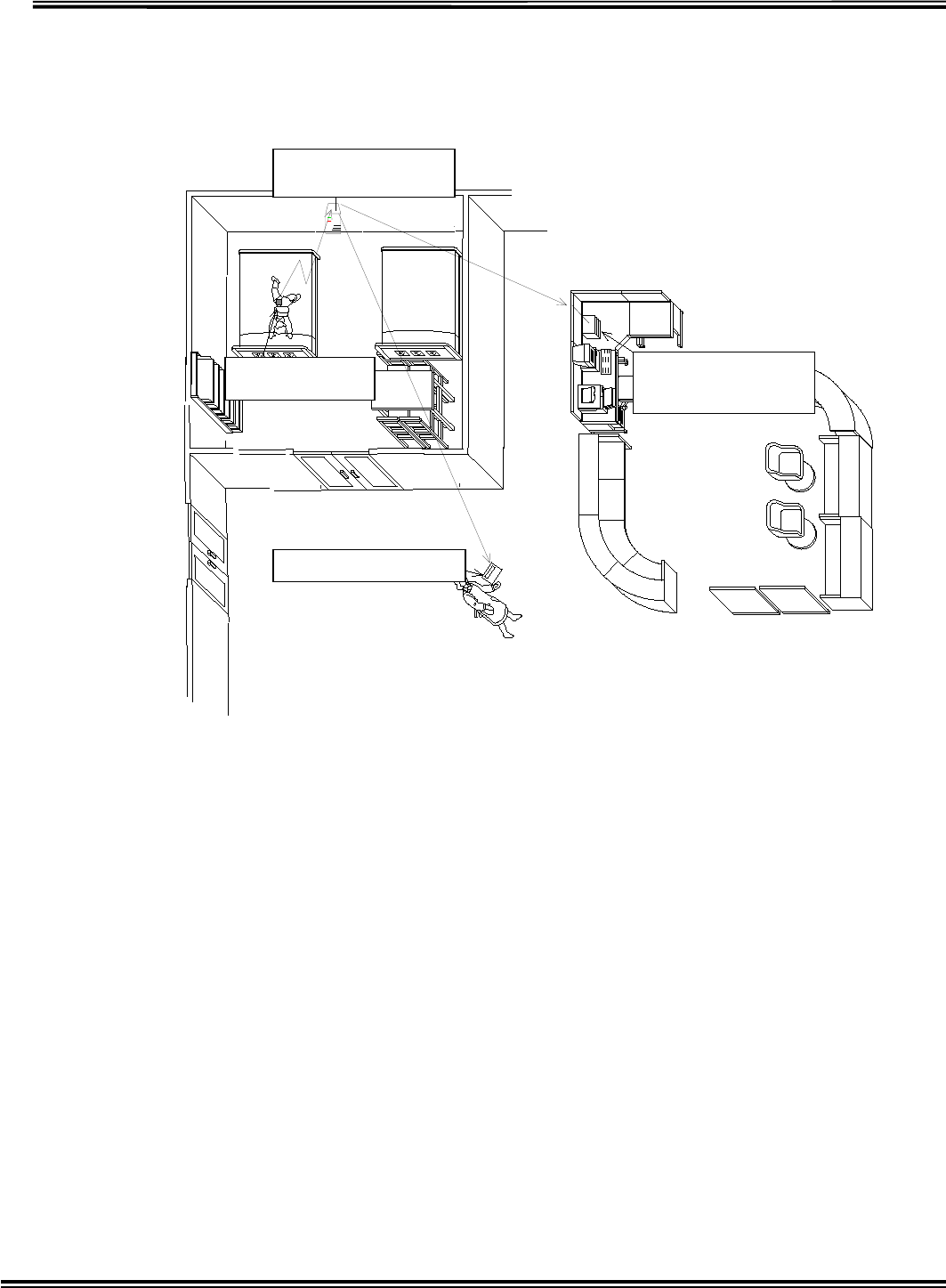
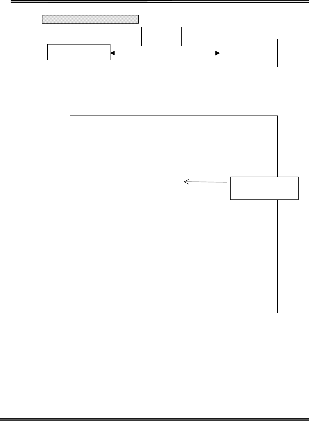
[1] Wetness Sensing System
(1) Overview
’†Œp‹@
ŒÅ’èŒ^ŽóM‹@
Œg‘ÑŒ^•\ Ž¦‹@
‘—M‹@
—¾•êŽº
‹Žº
This Wetness Sensing System is comprised with transmitters, transponders
and receivers, which inform caregivers of sensing moisture in a diaper. Once
wetness sensor incorporated into diaper is aware of moisture, the transmitter
including sensor puts out the signal to the transponder and then to the receiver.
Handy-receiver
Station-receiver
(option)
Transmitter
Transponder

RX-W1 Page 5
Specifications
■TRANSMITTER
Frequency 318.125M, 318.500M, 318.875M, 319.250MHz
RF Output Power 2400µV/m (67.6dBm) at 3 m
Frequency stability ±0.001
Identification Area ID199, Individual ID 199
Modulation system Variable reactance frequency modulation
Maximum Deviation ±4 kHz
Power Source 3V (lithium battery CR2032)
Battery Life about 3 months ( dropped to 2.5V)
■TRANSPONDER
Receive system Double-conversion superheterodyne
Receiving Frequency 1 318.125M, 318.500M, 318.875M, 319.250MHz
Receiving Frequency 2 314.500M~314.725MHz(25kHz step)
Sensitivity -113dBm for 12dB SINAD
Intermediate frequencies 1st 21.7MHz
2nd 450kHz
Transmitting Frequency 314.500M~314.725MHz(25kHz step)
RF output power 2250µV/m ( at 3 m )
Frequency stability ±0.001
Modulation system Variable reactance frequency modulation
Maximum Deviation ±4 kHz
Power supply requirement DC,AC9V 0.1A AC adaptor
Battery Life about 12 hours
■RECEIVER
Receive system Double-conversion superheterodyne
Receiving Frequency 1 318.125M, 318.500M, 318.875M, 319.250MHz
Receiving Frequency 2 314.500M~314.725MHz(25kHz step)
Sensitivity -113dBm for 12dB SINAD
Intermediate frequencies 1st 21.7MHz
2nd 450kHz
Frequency stability ±0.001
Power supply requirement DC,AC9V 0.3A AC adaptor
Battery Life about 5 hours
RX-W1 Page 6
Location and Function of Controls
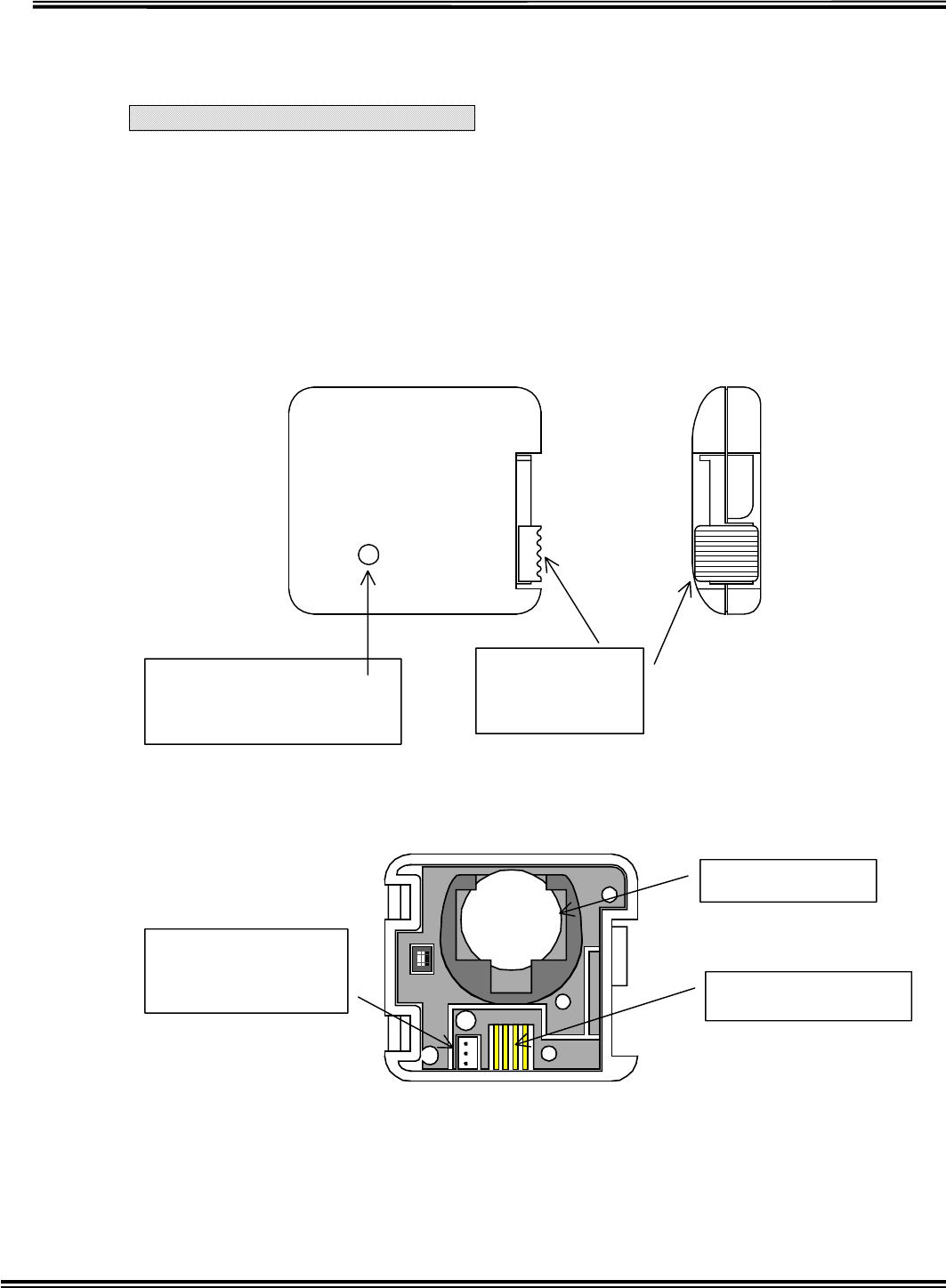
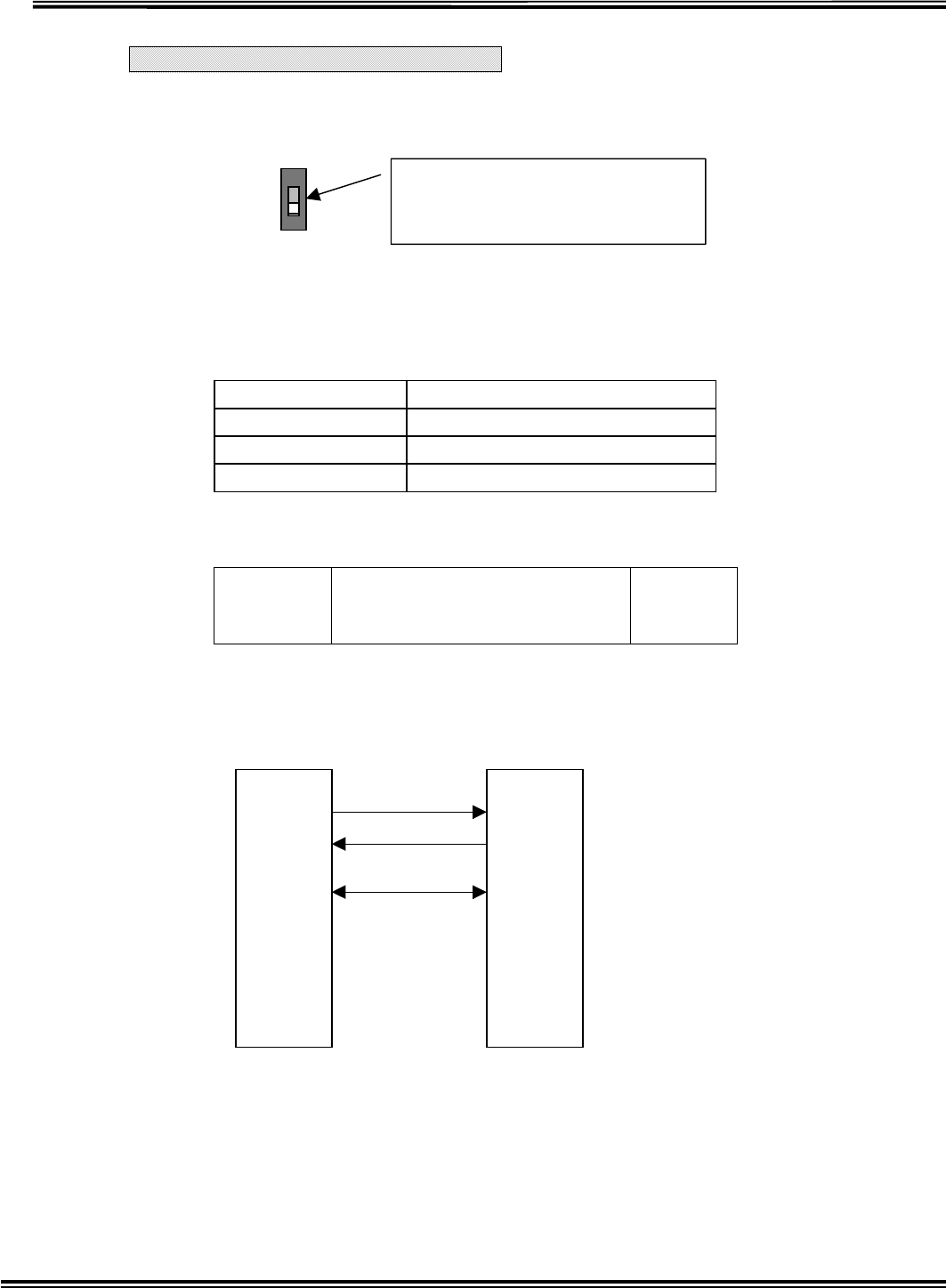
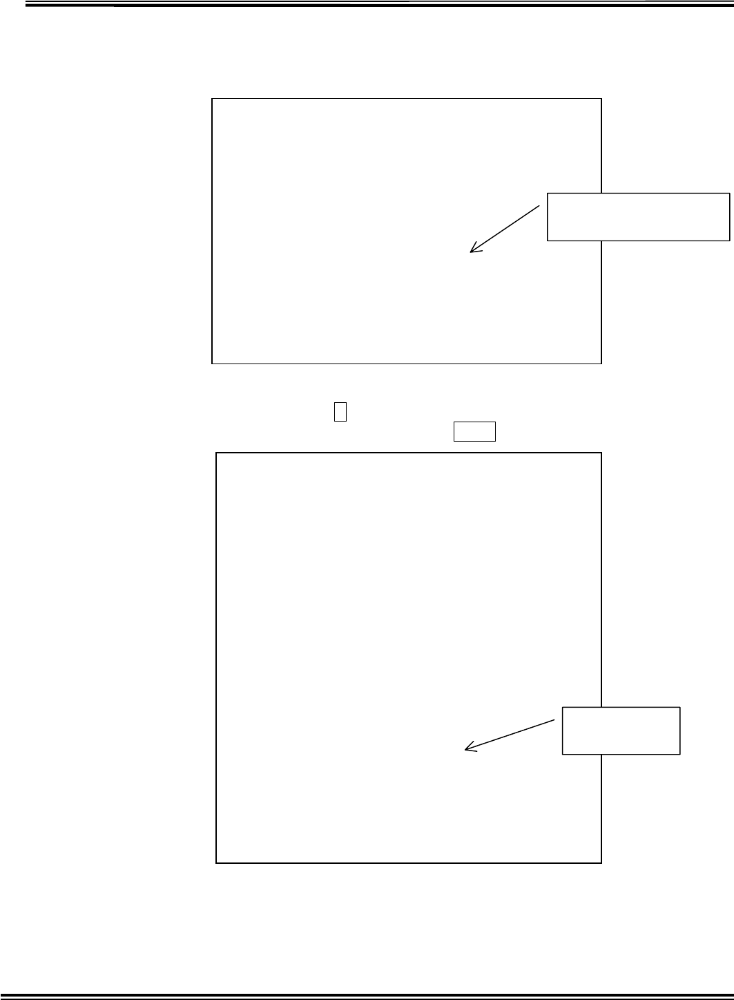
Transmitter Introduction
(1) overview
Sensing devise (sensor) is connected to transmitter. Once sensing devise senses moisture,
transmitter will send signal to transponder.
()Each Designation
Indicator Light
Blue light flash in sensing wet.
Red light flash in battery shutoff
Slid Tab
Rock in upper
Open in down
Battery Holder
Sensor Terminal
Cloning Terminal
Use in Transmitter
setting.
RX-W1 Page 7
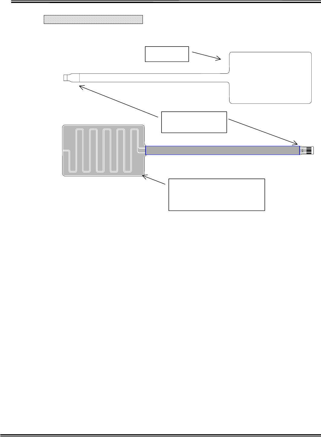
Sensor Introduction
Sensor
Moisture sensing part
A
ttach to a disposal diaper
with double-adhesive tape
Sensor
Electrode
A
lways I love ai
(t)
RX-W1 Page 8
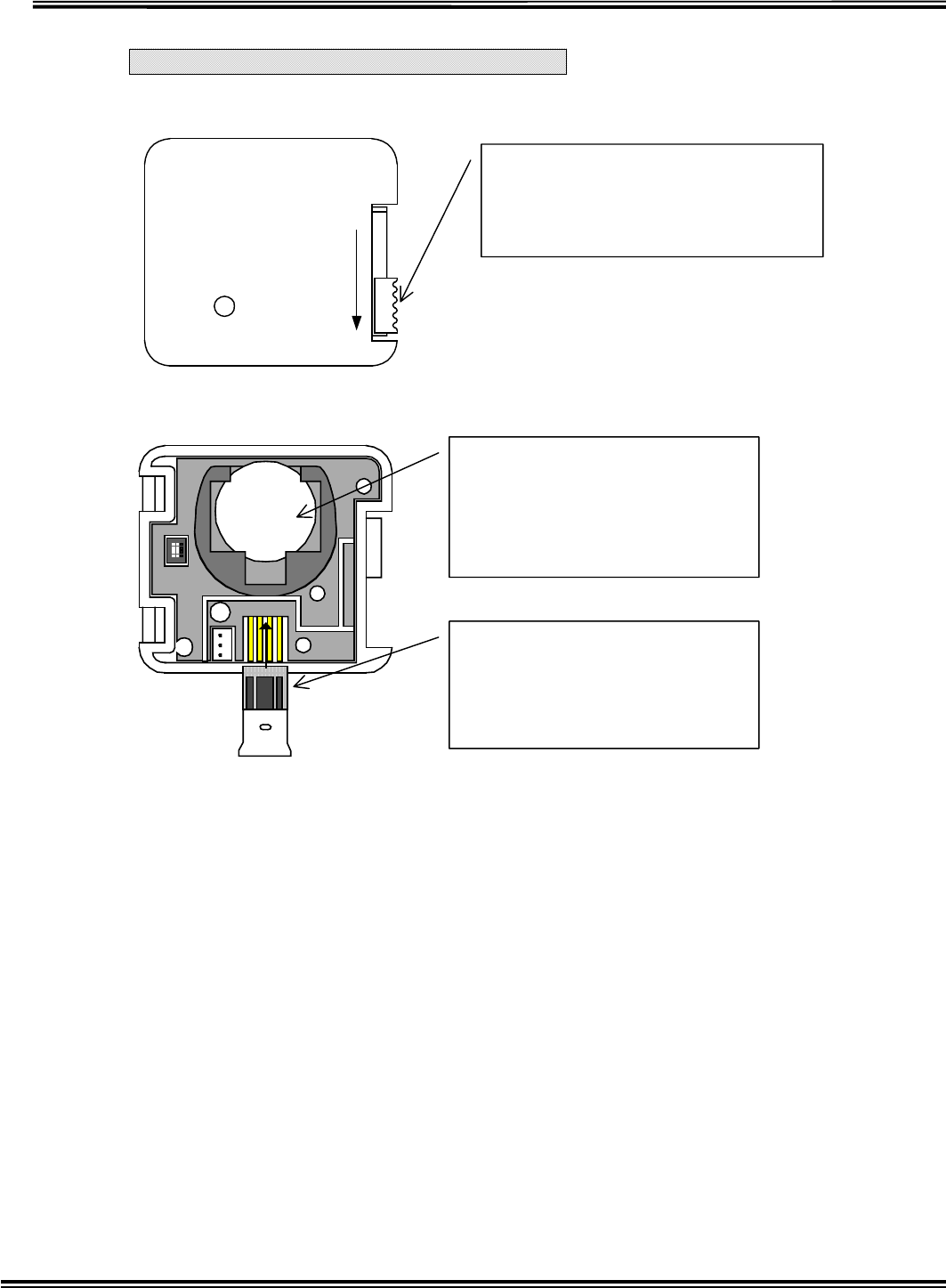
Transmitter and Sensor Operating
Open-Close Operation
Method of Battery desorption and Sensor Attachment
To open this case, release the lock
by sliding this tab underneath.
To lock the case is sliding this tab
upward in closed status.
Battery desorption
Installation
Cant the battery slowly.
Disinstallation
Push the battery upward.
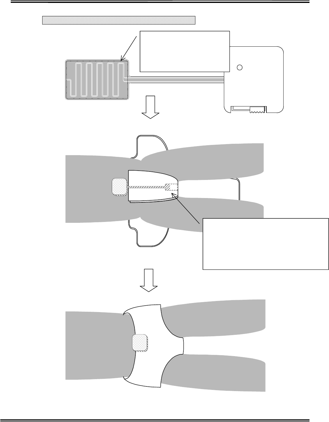
Sensor Installation
Put the Sensor into the
connector deeply and embed
in guide pin from above to
p
revent to dro
p
out.
RX-W1 Page 9
Sensor Installation to Disposal Diaper
After attach the sensor, put the cover on a diaper and then fix the
The double-adhesive tape is
attached to this side. Note
that attaching the tape to
wrong side will be cause
malfunction.
ai
A
ttach the sensor to prospected part for
wetting in a disposal diaper.
NOTE: Attaching firmly with no space
between the sensor and a diaper.
If there is a distance, the sensor may not
sense moisture in a disposal diaper.
RX-W1 Page 10
transmitter.
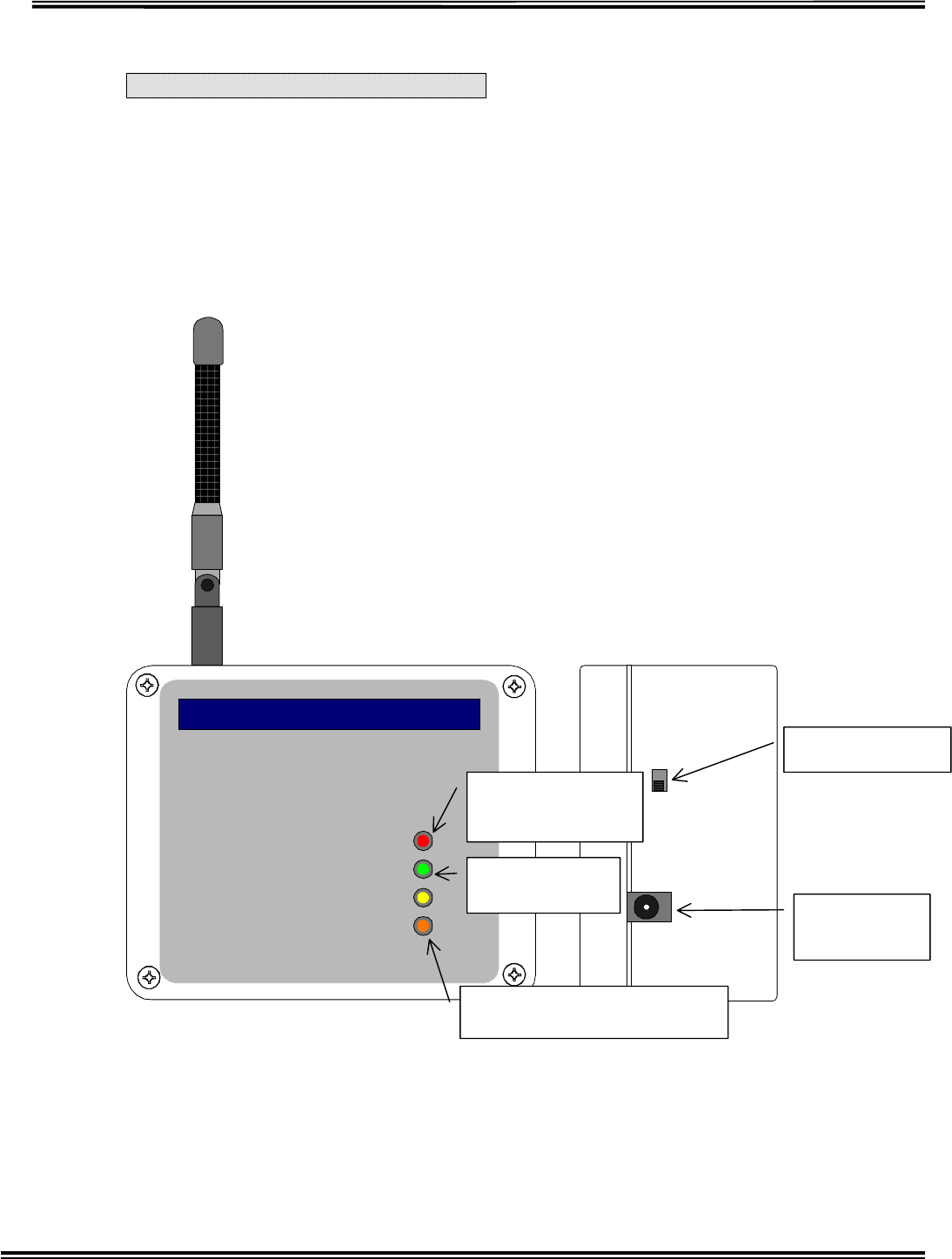
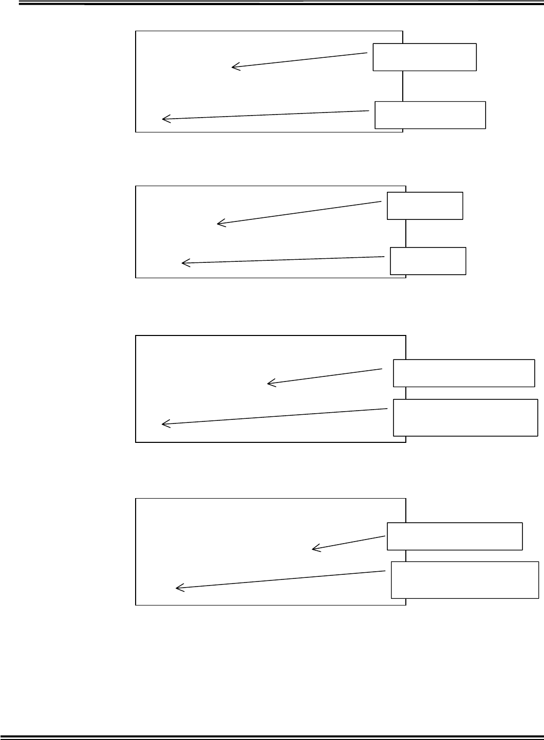
Transponder Introduction
Overview
Transponder receives signal from Transmitter and then transmits to Receiver.
It transmits the signal received from Transmitter to another Transponder.
Each Designation
Directions
The transponder is located in the signal receivable area from Transmitter.
Power
TX
RX
BT
NKK
Wetness Sensing System
CODE ALERT
Power-on Switch
Power Supply
Terminal
Indicator light
for transmitting
Flash when transmittin
g
.
Indicator light fo
r
receiving
Indicator light for Battery
Shutoff
RX-W1 Page 11
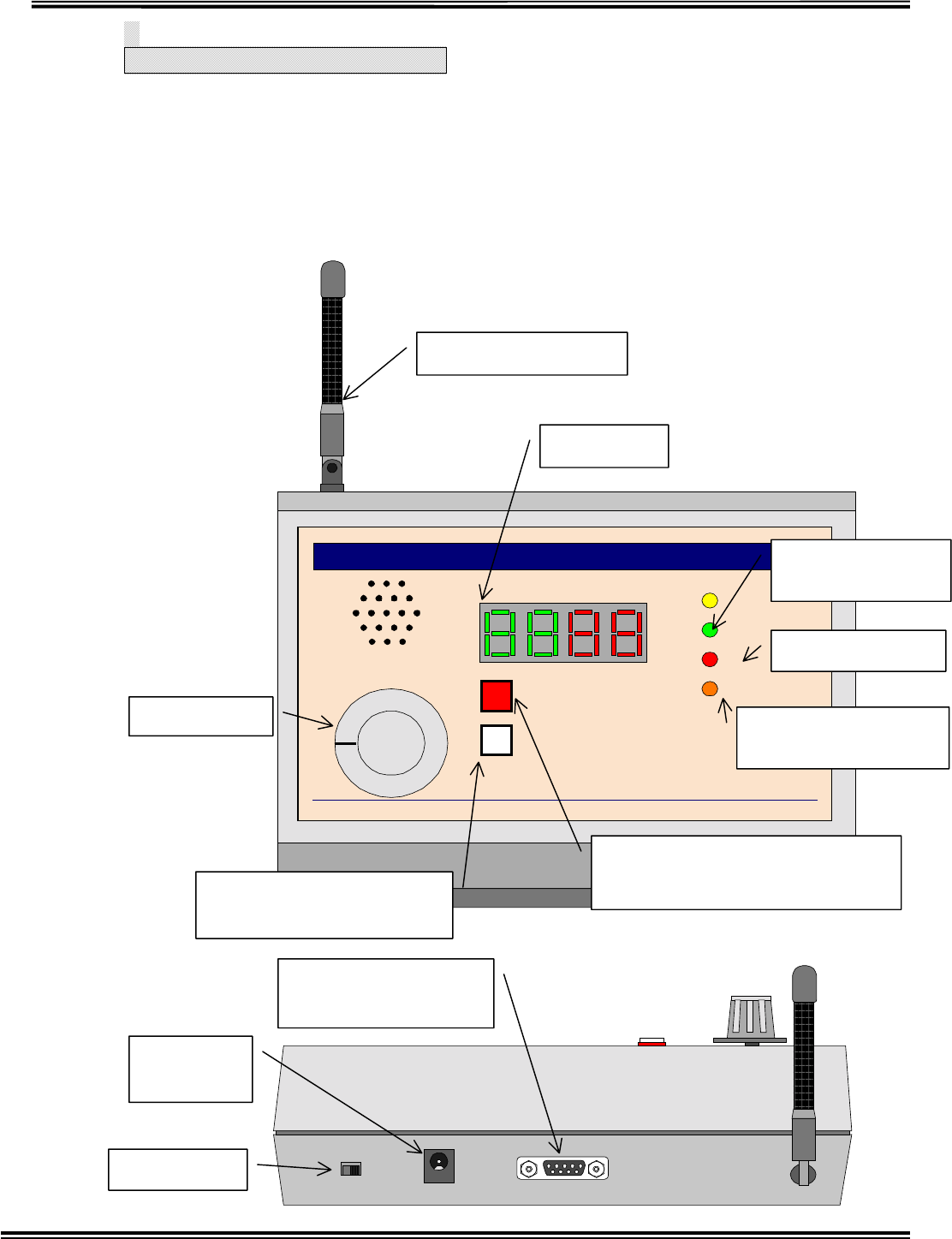
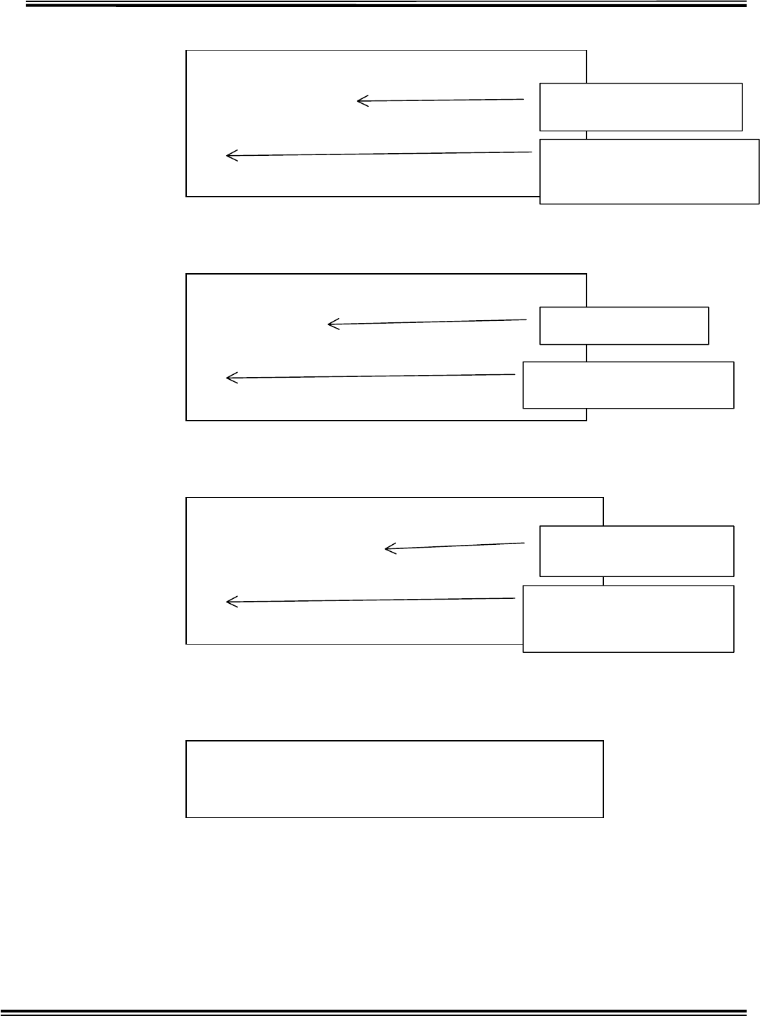
Receiver Introduction
1. Overview
When the receiver receives signal from the transponder, it informs caregivers
of received signal information (e.g. sense moisture or battery shutoff) by alarm
of melodies and display.
Each Designation
Power
RX
LOW BATTERY
VOLUME
BT CLEAR
TRANSMITTER ID
NKK
Wetness Sensing System
COM
CODE ALERT
OFF
1
23
TX BATTERY
Receiving Antenna
Power-on
V
olume Control Ta
b
ID Reset button for Transmitter
Battery Shutoff
Pager Controller &
Cloning Terminal
Warning LED for Transmitter Battery Shutoff.
A
cknowledge button for Transmitter
B
a
tt
e
r
y
S
hut
o
ff
External Termina
l
for Power Supply
Flash when transfer to PC
Indicator Light for receiving
Flash when receiving
Indicator light for Batter
y
Shutoff
FlashinBatteryshutoff
RX-W1 Page 12
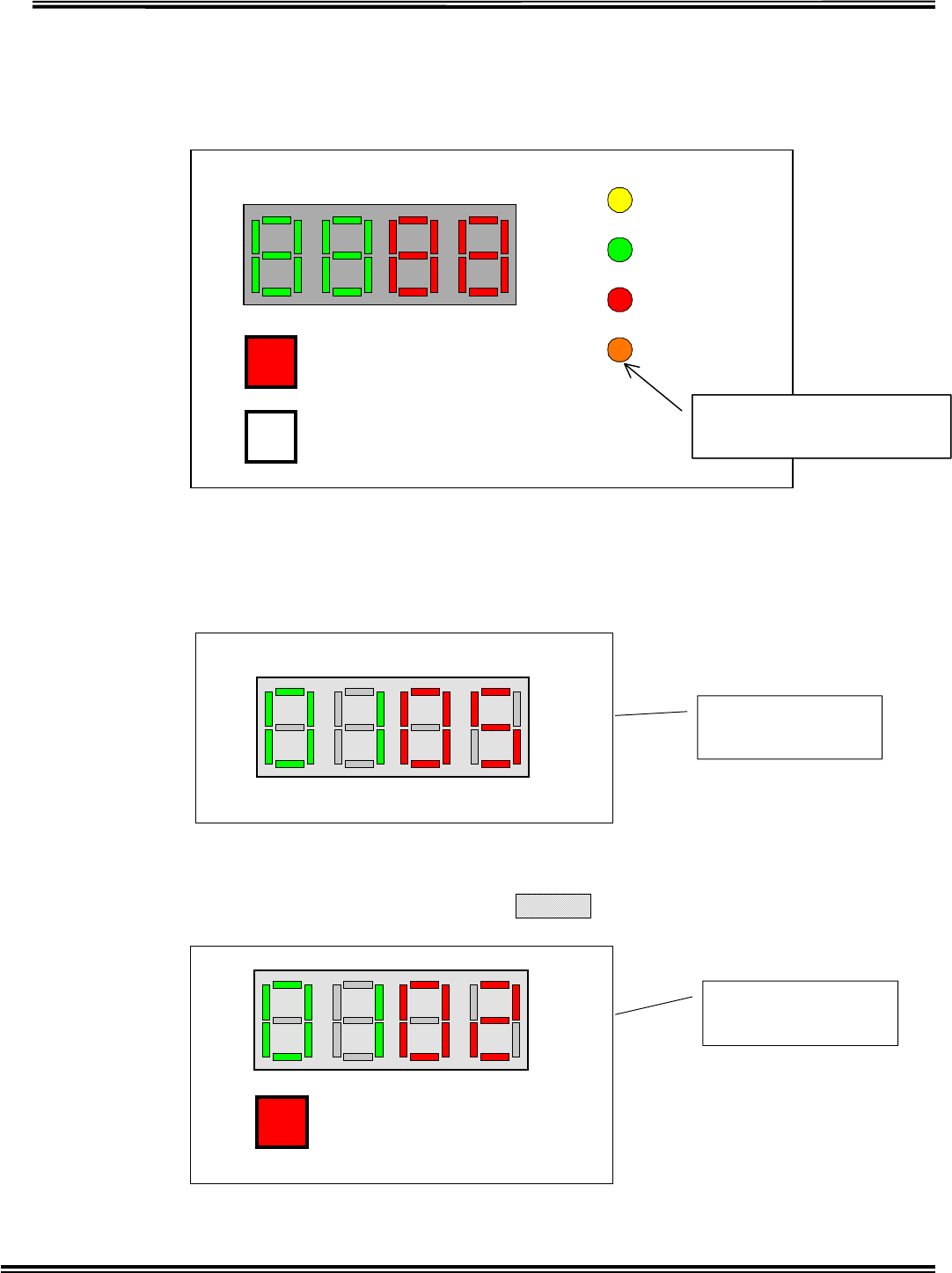
a.
1 Display Receiver Battery Shutoff
When the battery of receiver run down, LED will flash.
Information Display
When receiving the signal of sensing moisture in a diaper, it
displays Area ID in right two-digit and transmitter ID in left
two-digit. (NOTE: In case of sensing multiple IDs, it displays
those IDs in turn.)
(Example of Display 1)
Example of Display 2
When flashing “Warning LED for Battery Shutoff”, push “Acknowledge
button for Transmitter Battery Shutoff”, is displayed.
Power
RX
LOW BATTERY
BT CLEAR
TRANSMITTER ID
COM
TX BATTERY
Transmitter ID
5 in Area 1 is
Transmitter ID 2
in Area 1 runs
d
Indicator light for Battery
Shutoff
Flash in Battery shutoff
TX BATTERY

RX-W1 Page 13
7Receiver Operation
Turning on power, current receiving channel for the transmitter is displayed in 7
segment Display with red LED and current receiving channel for the transponder in 7
segment display with green LED, like for 5sec, after that it will clear the
ID.
When the transmitter senses moisture in a diaper, the receiver displays Area ID and
Transmitter ID and puts melodies on.
Once Transmitter IDs are received, it continues displaying these IDs till the signal
from the transmitter is cut off for 30sec. Those IDs will be cleared automatically
when the signal is aborted (i.e. it displays those IDs till the diaper attached the
sensor is changed.).
1 Volume Control SW
It changes Volume of melodies as four stage (large, middle, small and OFF).
2 TXBATTERYSWLED
Square red LED flashes in Transmitter Battery Shutoff.
Transmitter ID which runs out is displayed during pushing this SW. (In case of
detecting multiple IDs, it displays those IDs in turn.)
3 BT CLEAR SW
Battery Shutoff LED will be lighted out and its IDs will be cleared after checking
which ID is detected by pushing TX Battery SW and changing the battery.
NOTE: Be sure to clear detected IDs after changing the battery
4 Power Supply
AC adapter more than 0.3A, 9V(DC, AC) is available.
In electricity failure, this system can work about for 5 hours by using built-in
rechargeable battery.
RX-W1 Page 14
3Inside Views, Dip-SW Setting
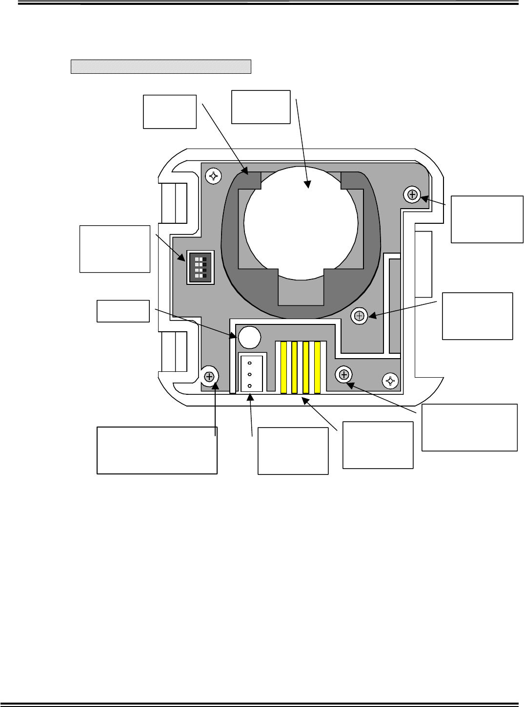
Transmitter Inside View
Fig.3-1 TRANSMITTER
Battery
Holder
Battery
CR2032
CT1
Frequency
A
DJUST
V
R1
RF Power
A
DJUST
SW1
MODE
Select
LED
CT2
A
NT Matching
A
DJUST
CN1
SENSOR
Connect
CN2
CLONING
Port
CT3
SENSOR Sensitivity
A
DJUST
RX-W1 Page 15
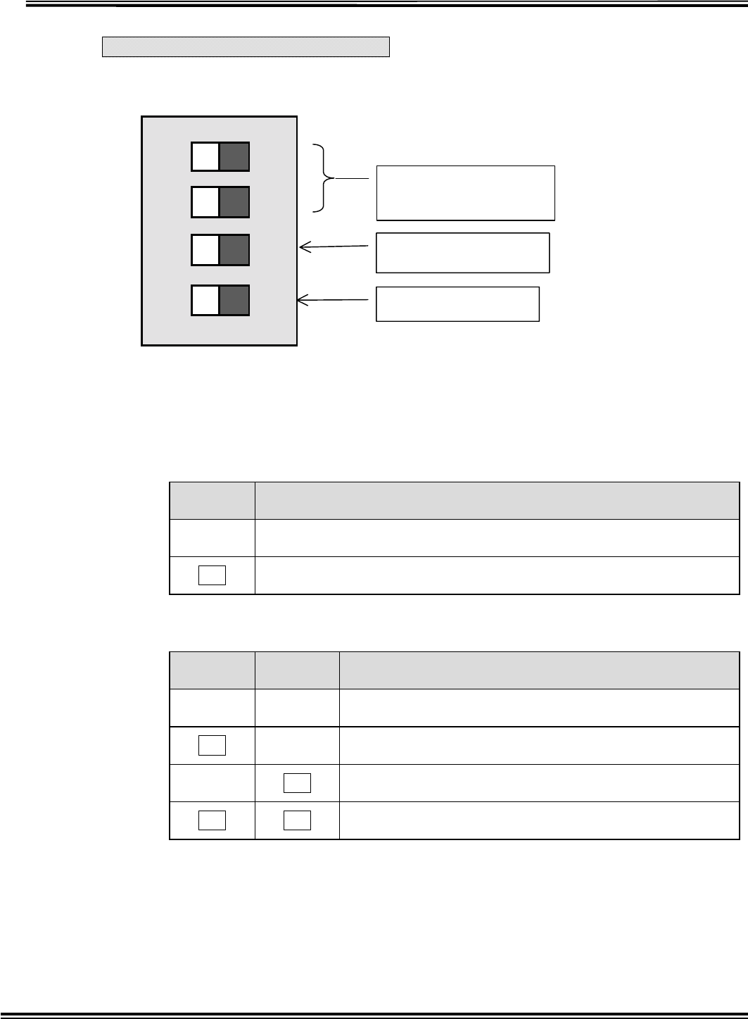
Transmitter Dip-SW Setting
SW1MODESELECT
TESTMODESELECTIONSW1-1
SW1-1 is ON when turning on power, it will enter into Test Mode.
It will be transfered data continuously in the Test Mode. To stop the continuous
transfer is turning SW1-1 off in Test Mode.
Turning on power again with SW1-1 OF enters into Normal Mode.
SENSOR TYPE SELECTIONSW1-2
SW1-2 SENSOR TYPE
OFF Capacitortype Sensor
ON Resistortype Sensor
Capacitor Sensitivity SelectionSW1-3,4
SW1-3 SW1-4 Capacitor Sensitivity
OFF OFF Maximum Sensitivity about 3.5pF
ON OFF Middle Sensitivity about 4.5pF
OFF ON Lower Sensitivity about 5.5pF
ON ON Minimum Sensitivity about 6.5pF
1234
ON
ON=TEST MODE
Sensor Type Selection
Capacitor Sensitivity
Selection
RX-W1 Page 16
Transponder Inside View
Fig.3-2 TRANPONDER
Transponder ANT SW1
Power SW
F1
Fuse 1A
CN1
EXT Power
Supply
Input 9V
CN3
Battery
Connect
SW3-4
Test Mode
SW3-13
Transponder ID
Select
SW2
Receiving
Channel
SW1
Transponder
Channel
CN2
Cloning
Port
RX-W1 Page 17
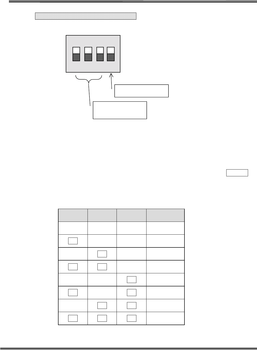
Transponder Dip-SW Setting
SWMODESELECT
TESTMODESELECTSW3-4
SW1-1 is ON when turning on power, it will enter into Test Mode.
Data will be received continuously in the Test Mode. When SW3-1 is OFF, it
receives data at Transmitter receiving frequency. When SW3-1 is ON, it
receives data at Transponder receiving frequency. In that case, if RSSI is ON
green LED will be flashed, if N-DET is ON red LED will be flashed.
In Test Mode, changing SW3-4 into OFF will be in Transfer Mode. At that time,
if SW3-1 is OFF it transfers only carrier wave, if ON it transfers ID
continuously.
Restart with SW3-4 OFF, it returns to normal mode.
Transponder ID Selection SW3-13
SW3-1 SW3-2 SW3-3 ID
OFF OFF OFF 1
ON OFF OFF 2
OFF ON OFF 3
ON ON OFF 4
OFF OFF ON 5
ON OFF ON 6
OFF ON ON 7
ON ON ON 8
NOTE: In case of connecting multiple transponders, be sure not to set same Transponder IDs.
1 2 3 4
ON
ON=TEST MODE
Transponder ID
Selection

RX-W1 Page 18
Receiving Channel Selection SW2
Receiving channel means receiving frequency when receiving the signal from
Transmitter.
SW2 Receiving CH Receiving Frequency
0 1 CH 318.125MHz
1 2 CH 318.500MHz
2 3 CH 318.875MHz
3 4 CH 319.250MHz
NOTE: It is impossible to receive the signal if the transmission wave has
no
accordance with receiving wave.
Transponder Channel Selection SW1
Transponder Channel means identical frequency at which multiple
Transponders transfers and receives mutually.
SW1 Transponder CH Transponder Frequency
0 1 CH 314.500MHz
1 2 CH 314.525MHz
2 3 CH 314.550MHz
3 4 CH 314.575MHz
4 5 CH 314.600MHz
5 6 CH 314.625MHz
6 7 CH 314.650MHz
7 8 CH 314.675MHz
8 9 CH 314.700MHz
9 10 CH 314.725MHz
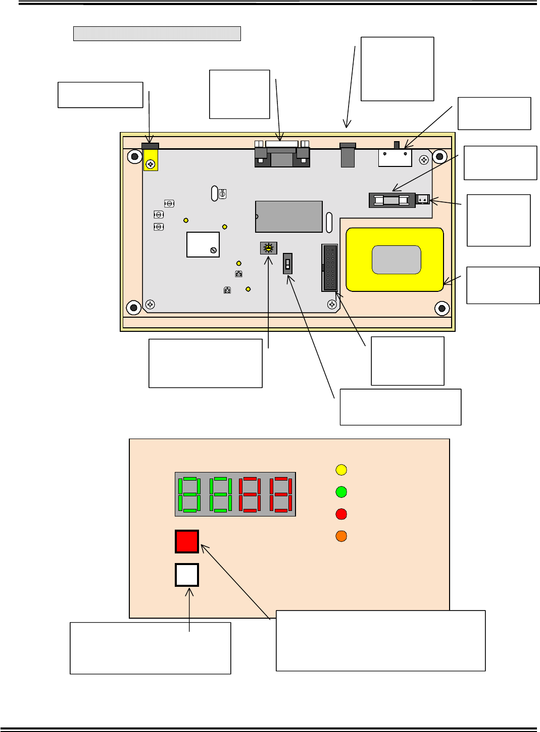
RX-W1 Page 19
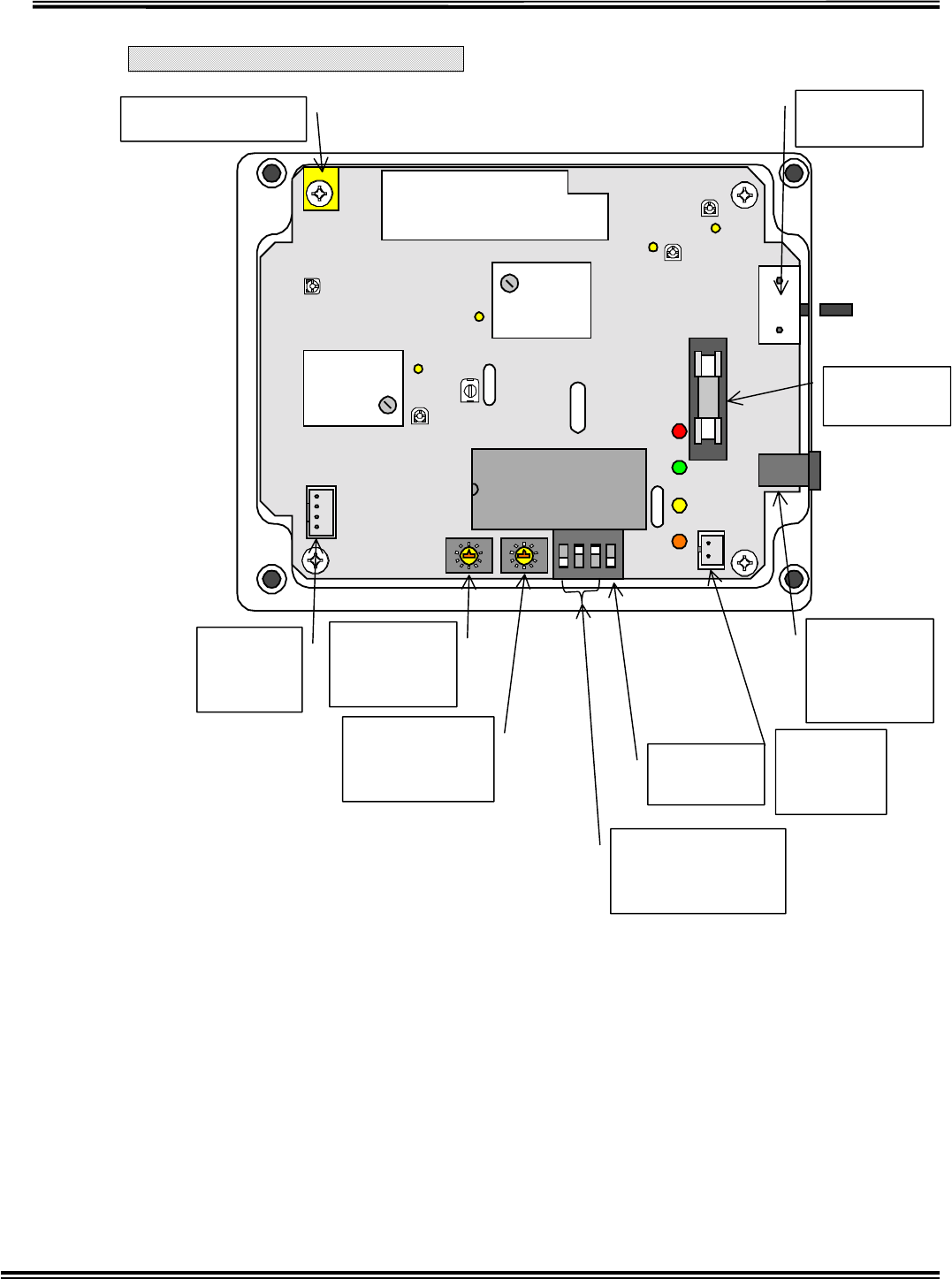
Receiver Inside View
Receiver ANT CN2
Cloning
Port SW2
Power SW
CN1
EXT Power
Supply
Input 9V
F1
Fuse 1A
CN3
Battery
Connect
Battery
4.8V
CN6
To Display
Connect
SW1
Pager Controller Set
SW3
Receiving Channel
Select
Power
RX
LOW BATTERY
BT CLEAR
TRANSMITTER ID
COM
TX BATTERY
TX BATTERY SW
Warning LED for Transmitter Battery Shutoff.
A
cknowledge button for Transmitter Battery
Shutoff
BT CLEAR SW
ID Reset button for Transmitter
Battery Shutoff
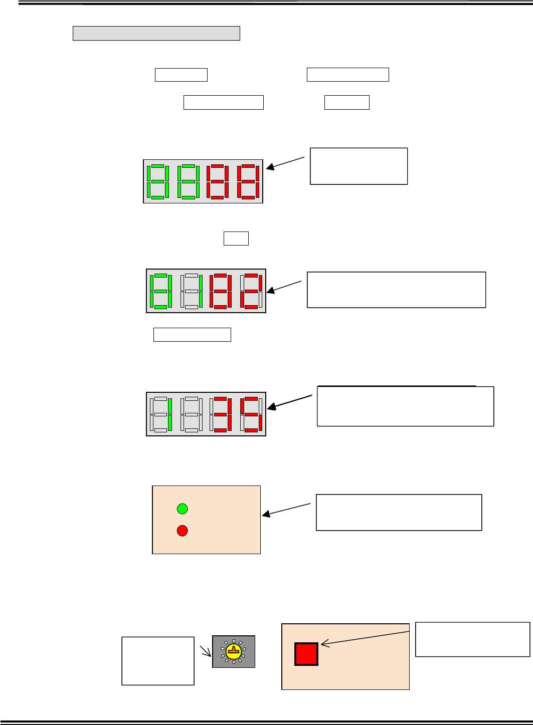
RX-W1 Page 20
Receiver Test Mode 1
TESTMODESELECT
When Power SW is ON in pushing BT CLEAR SW on Front Panel, it will be
Test MODE 1.
First, when BT CLEAR SW is pushing is displayed in 7segment LED
for 1sec and then the LED of RX, COM and TXBATTERY is flashed
sequentially.
Second, it displays the receiving channel of transmitter and transponder which
are in memory, like 0102Transponder = 1CH, Transmitter = 2CH.
When BT CLEAR SW is released, it will be in Transponder receiving acknowledge
Mode. Transponder receiving channel is displayed in left side LED with green and RSSI
Levelradio field intensity is displayed in right side LED with red.
When RSSI is ONRSSI40, RXLED is flashed with green and when N-
DET is ON, COMLED is flashed with red.
To change the Transponder receiving channel is switching over SW3 of Rotary
Dip SW in the Main Board to target channel, and then push the TX BATTERY
SW in the Front Panel to memory the setting.
7 Seg. LED
A
ll Test Display
TRANSMITTER ID
TRANSMITTER ID
Transponder Receiving CH=1ch
Transmitter Receiving CH =2ch
TRANSMITTER ID
Transponder Receiving =1ch
RSSI Level=35
RX
COM
RSSI ON=RX LED ON
N-DET ON=COM LED ON
TX BATTERY
SW3
Receiving
Channel
Memory SW for
TX BATTERY SW
TRANSMITTER ID
Transponder Receiving CH =1ch
RSSI Level=35
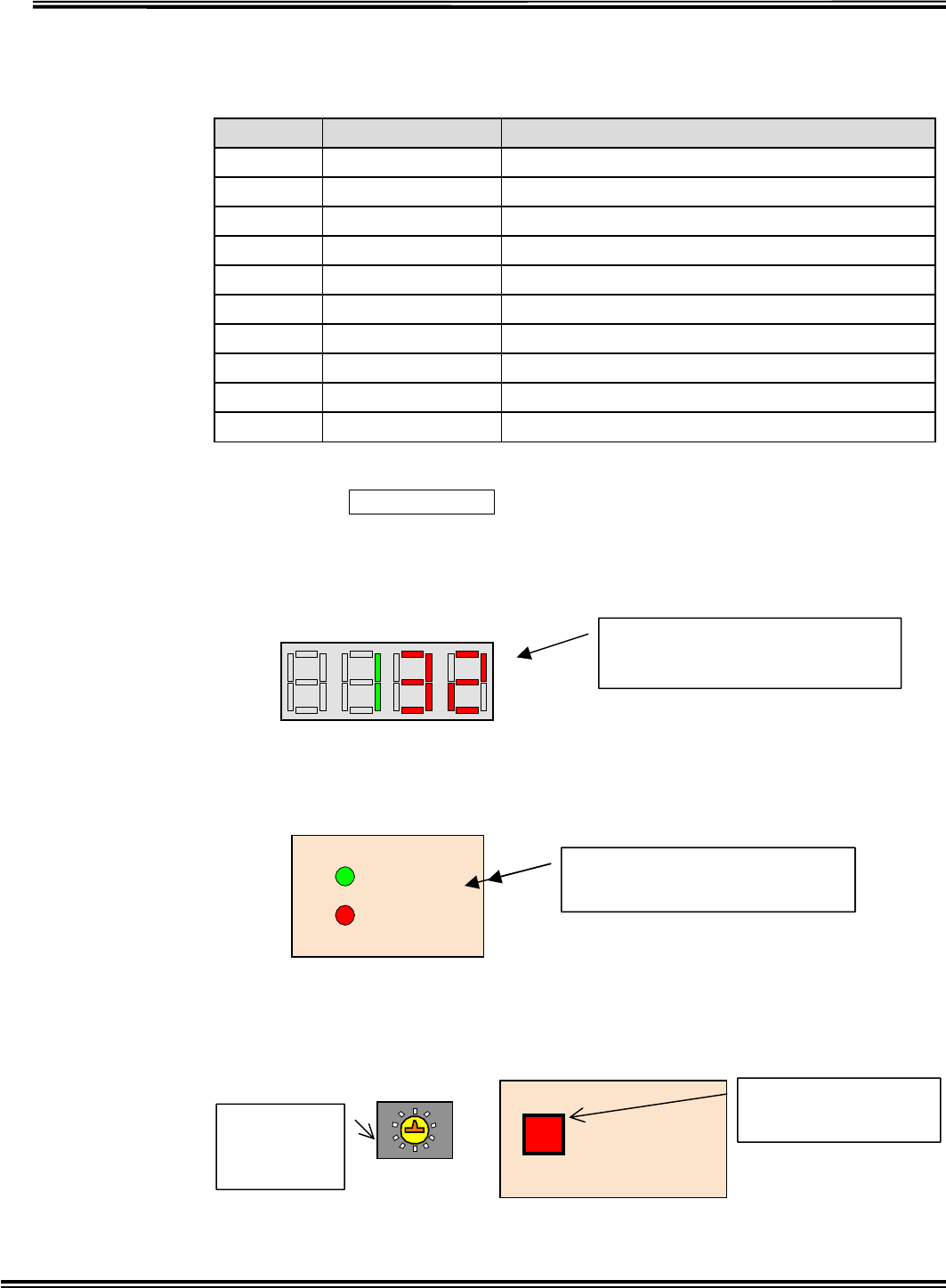
RX-W1 Page 21
Transponder Channel Select SW3
Transponder Channel means receiving frequency when receiving the signal
from Transponder.
SW1 Transponder CH Transponder Frequency
0 1 CH 314.500MHz
1 2 CH 314.525MHz
2 3 CH 314.550MHz
3 4 CH 314.575MHz
4 5 CH 314.600MHz
5 6 CH 314.625MHz
6 7 CH 314.650MHz
7 8 CH 314.675MHz
8 9 CH 314.700MHz
9 10 CH 314.725MHz
After pushing BT CLEAR SW in Front panel again, it will be in Transmitter
receiving acknowledging Mode. Current Transponder receiving channel is
displayed in left side LED with green and RSSI Levelradio field intensity
is displayed in right side LED with red.
When RSSI is ONRSSI40, RXLED is flashed with green and when N-
DET is ON, COMLED is flashed with red.
To change the Transponder receiving channel is switching over SW3 of Rotary
Dip SW in the Main Board to target channel, and then push the TX BATTERY
SW in the Front Panel to memory the setting.
TRANSMITTER ID
Transmitter CH = 1ch
RSSI Level=32
RSSI ON=RX LED ON
N-DET ON=COM LED ON
RX
COM
TX BATTERY
SW3
Receiving
Channel
Memory SW for
TX BATTERY SW
RSSI ON=RX LED ON
N-DET ON=COM LED ON

RX-W1 Page 22
Transmitter Receiving Channel Select SW3
Receiving channel means receiving frequency when receiving the signal from
Transmitter.
SW3 Receiving CH Transmitter Receiving Frequency
0 1 CH 318.125MHz
1 2 CH 318.500MHz
2 3 CH 318.875MHz
3 4 CH 319.250MHz
NOTE: It is impossible to receive the signal if the transmission wave has
no accordance with the receiving wave.
It returns to normal mode by restart.
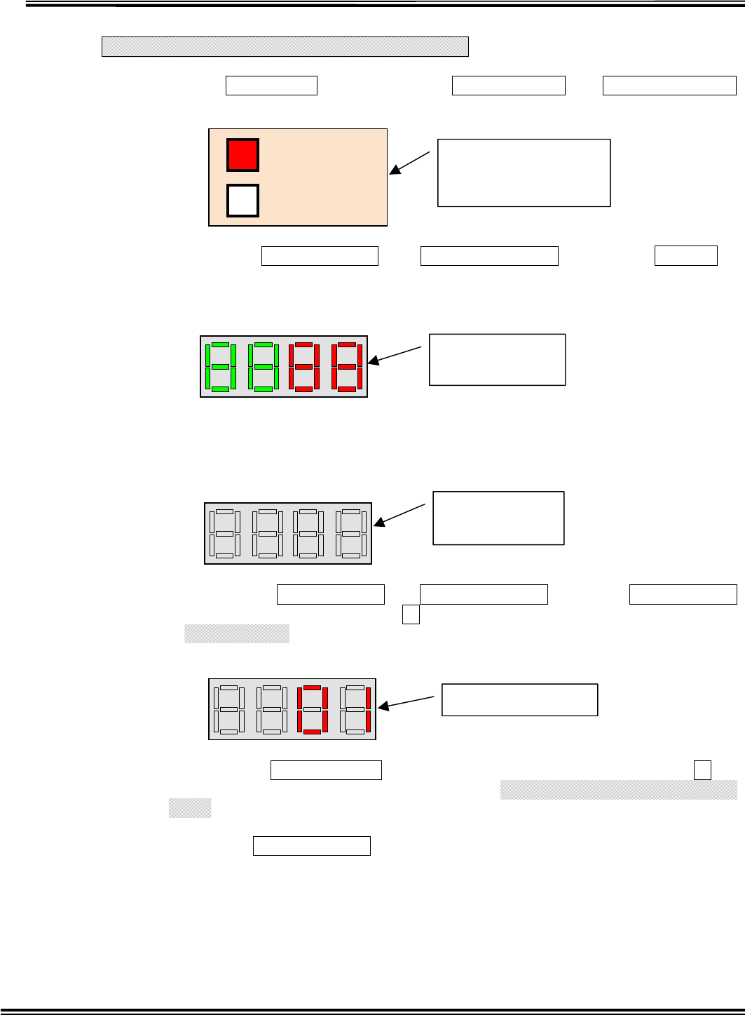
RX-W1 Page 23
Receiver Test Mode 2 (Melody Test)
WhenPOWER SW is ON in pushing BT CLEAR SW and TX BATTERY SW
on Front Panel simultaneously, it will enter into Test MODE 2.
First, when BT CLEAR SW and TX BATTERY SW is pushing, is
displayed in 7segment LED for 1sec and then the LED of RX, COM and
TXBATTERY is flashed sequentially.
The display of Seg. LED is cleared after 2sec.
Second, release BT CLEAR SW and TX BATTERY SW , and push BT CLEAR SW
once. It displays Melody Number 01 in7 seg. LED with red and sounds the melody
of Yankee Doodle from a loudspeaker only once except that Volume Control is OFF
In addition, if BT CLEAR SW is pushed again, it displays Melody Number 02 in7
seg. LED with red and sounds the melody of Oh Bury Me Not On The Lone
Prairie only once.
Each time BT CLEAR SW is pushed, it sounds 16 melodies and 1 audible
alarm to test these sounds.
It returns to normal mode by restart.
TRANSMITTER ID
TRANSMITTER ID
7 Seg. LED
A
ll Delete
BT CLEAR
TX BATTERY
BT CLEAR SW
TX BATTERY SW
Same time Push
TRANSMITTER ID
01=Yankee Doodle
7 Seg. LED
A
ll Test Display
TRANSMITTER ID
RX-W1 Page 24
PagerControllerProtocol
In case of using PAGERCONTROLLER, SW1 in Main Board should be ON.
If the SW1 is ON without connecting Pager Controller by mistake or Pager Controller
power is OFF, it alarms sound each 30sec.
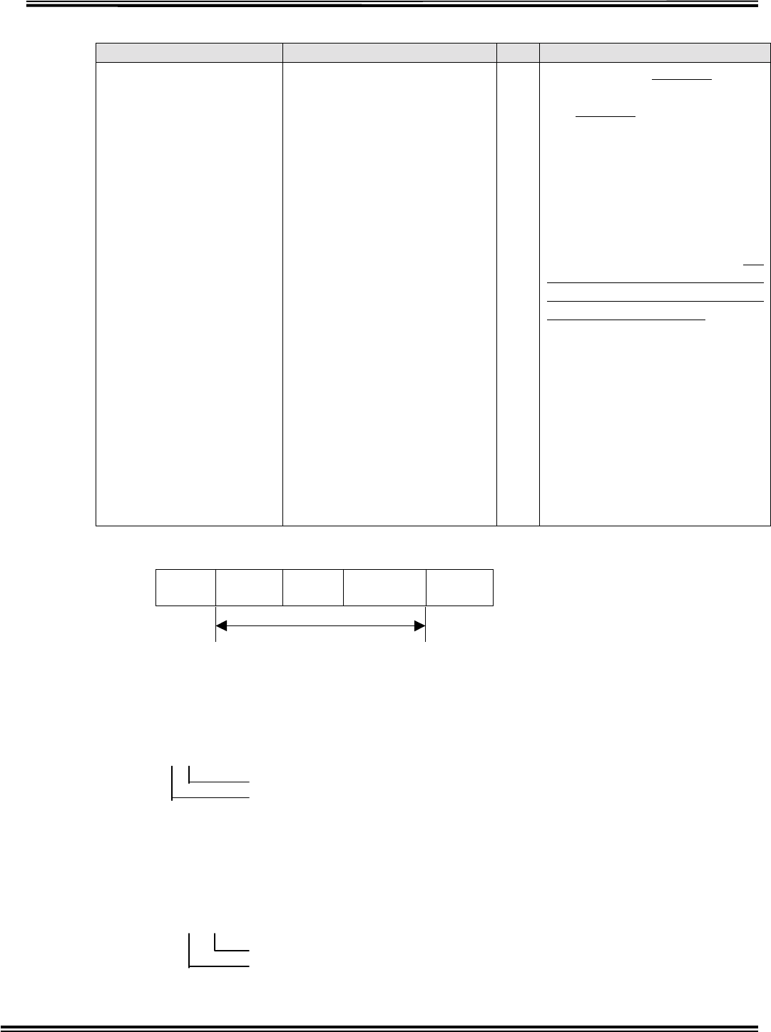
1. Pager Controller communicationForm
BAUD RATE 9600BPS
DATA BIT 8-BIT
PARITY NONE
STOP BIT 1BIT
2.Data Format
Start
BIT
(1bit)
DATA
(8bit) Stop
BIT
(1bit)
3.RS-232-C Connector
SW1
PAGERCONTROLLERON
Receiver(9Pin) PC(9Pin
1 CD
2 SD
3 RD
4 DTR
5 SG
6 DSR
7 RTS
8 CTS
9 RI
1 CD
2 RD
3 SD
4 DTR
5 SG
6 DSR
7 RTS
8 CTS
9 RI
RX-W1 Page 25
4.Cominucations Protocol
[PC] [Receiver]
[ Sensing Data
Transfer]
The Receiver
transfers sensing
information and
battery shutoff
information.
It transfers the
data periodically
each 5sec.
…
[BCC][CR]
Transmitter ID (4-
digits) which is sensing
moisture or battery
shutoff is transferred
after [:][K], and then
Transmitter status (”1”
= Sensing moisture, ”2”
= Battery shutoff, “3” =
“1” and “2”) is
transferred as single-
digit. When multiple
IDs or status is
transferred, they are
broken by and added
[BCC][CR] at the end.
When there are nothing
of transmitting
information,
[K][BCC][CR] are
transferred.
BCC Calculating Methods
:
(STX) K
(CMD) 0101
(ID) 1
(DATA) CN
(BCC)
Calculating Range
It gets the SUM from CMD to DATA and divides into MSB 4bits and LSB 4bits, and
then adds 40H and converts into 2 bytes word as hexadecimal.
Example 1
‘’‘’‘’
414243
LSB
MSB
Example 2
‘’‘’‘’‘’‘’‘’‘’‘’‘’‘’‘’
LSB
MSB
RX-W1 Page 26
ID Types
Transmitter ID
Transmitter ID “0608” is 4-digit number, first 2-digit is Area ID and last two-digit is
individual unique ID.
16 types of Area ID“01””16”(“01””10”[Hex])
99 types of Unique ID“01””99”(“01””63”[Hex])
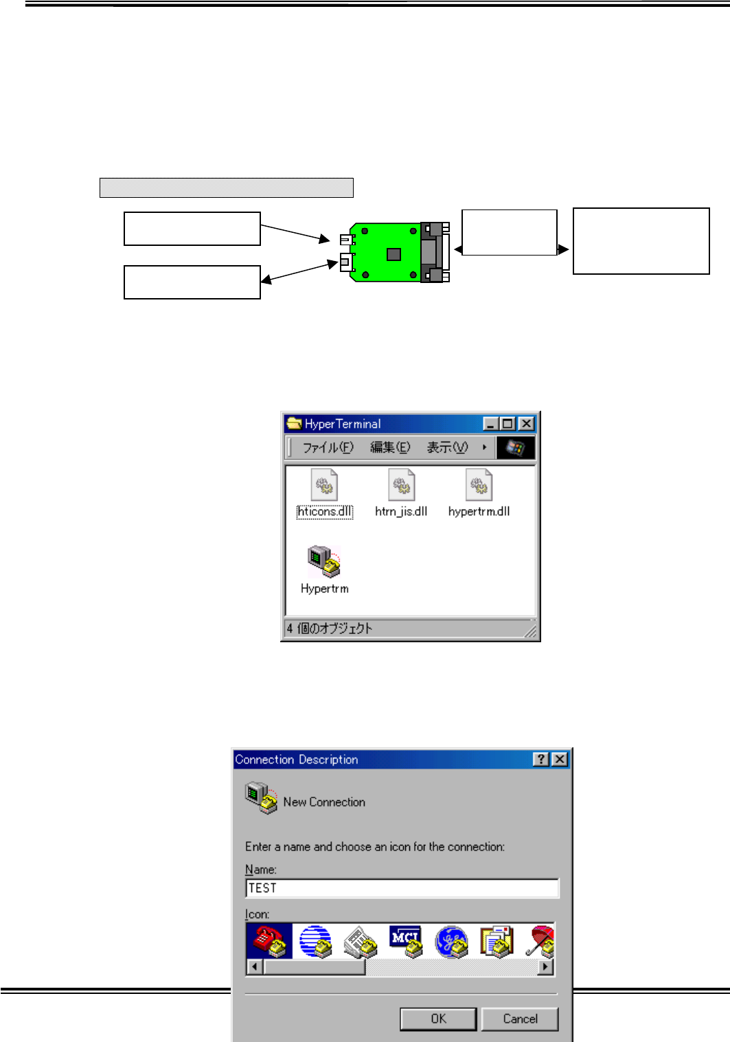
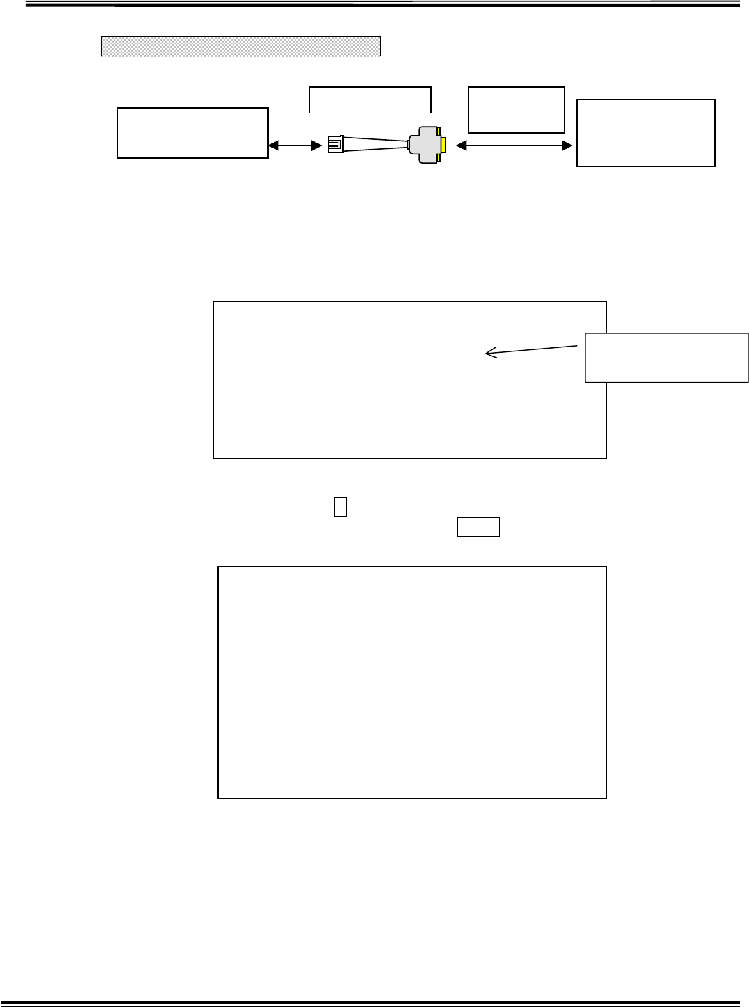
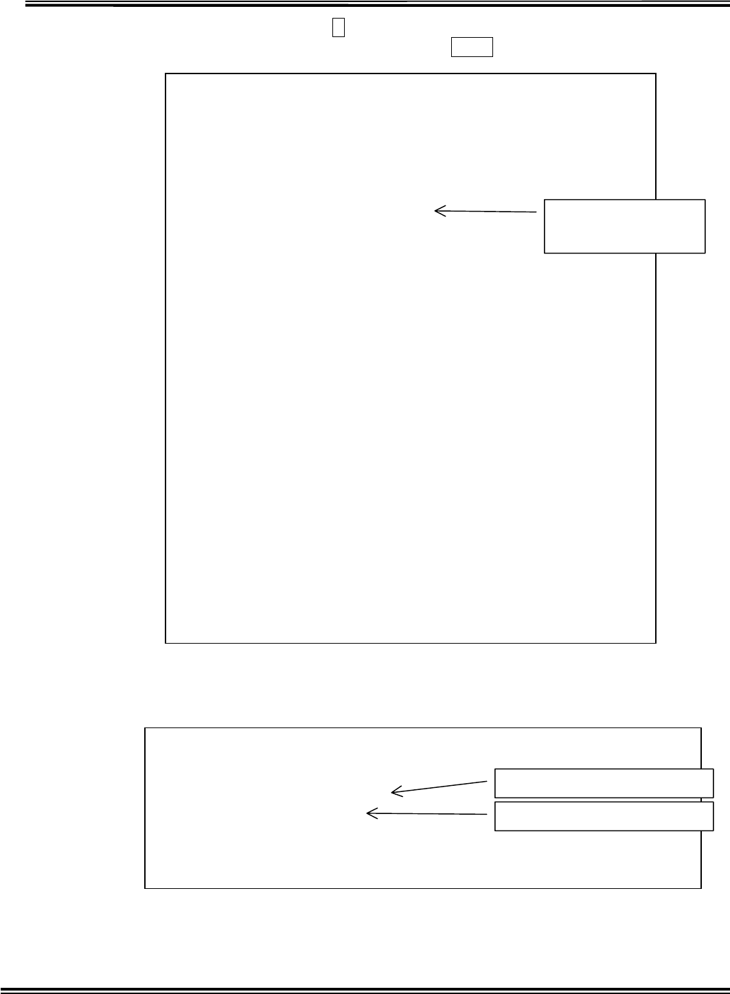
Transmitter Clone Mode
Fig.4-1 CONNECTION OF CLONING UNIT
Connect the cloning unit like above chart, and start up PC and then run “Hyper
Terminal” of Windows accessory.
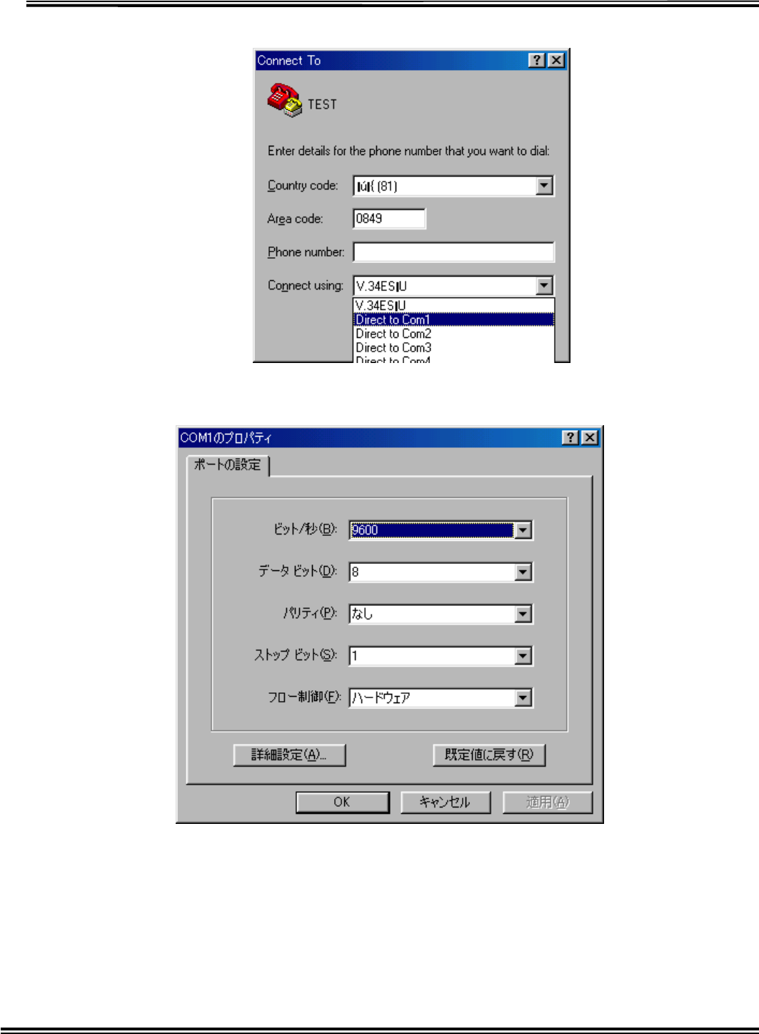
Fig.4.2 Initial window of Hyper Terminal
After running Hyper Terminal, the following window will open. Set as below.
TRANSMITTER
PC under
Windows 95 or
98
RS232C
Strai
g
ht cable
DC
V

RX-W1 Page 27
Fig.4-3-1 Start-up window of Hyper Terminal
RX-W1 Page 28
Fig.4-3-2 Setting window of COM PORT
Fig.4-3-3 Setting window of COM PORT
RX-W1 Page 29
The following Transmitter start-up screen (Fig.4-4) will be displayed after setting
Communication Port and Communication protocol and insert a battery.
Fig.4-4 Transmitter start-up screen
At this point when pushing C key within 5sec, the following screen (Fig.4-5) is
displayed and Mode Set can be changed. Pushing Enter key terminates the setting.
Fig.4-5Mode Set for Transmitter
#
##### TX69W01 Ver.1.0 ######
**** << Current Mode Status >> ****
Current Detection=[ Capacitor ]
1.ID No. = 0112
2.Resistor Detection Time = 3 (s)
3.Capacitor Detection Time = 10 (s)
4.Transmission Qty = 01
5.STOP Time = 10 (s)
6.Serial Modulation Qty = 06
Change Mode Set = [C] ? Execute = [Enter] ?
(Note: No Key, Auto Execute after 5 sec.)
Current setting status
of Transmitter
**** << Current Mode Status >> ****
Current Detection=[ Capacitor ]
1.ID No. = 0112
2.Resistor Detection Time = 3 (s)
3.Capacitor Detection Time = 10 (s)
4.Transmission Qty = 01
5.STOP Time = 10 (s)
6.Serial Modulation Qty = 06
**** << Mode Set >> ****
[1] = Country Select
[2] = ID No.
[3] = Resistor Detection Time
[4] = Capacitor Detection Time
[5] = Transmission Qty
[6] = STOP Time
[7] = Serial Modulation Qty
[0] = END
Select [1]-[7],[0] and Press [Enter]
>
Mode Set for
Transmitter
RX-W1 Page 30
Country Set (Select [] in Fig. 4-5)
Fig.4-6Country Set
Transmitter ID Set (Select [] in Fig.4-5)
Fig.4-7Transmitter ID Set
Setting of Resistor Detection Time. (Select [] in Fig.4-5)
Fig.4-8 Setting of Resistor Detection Time
Setting of Capacitor Detection Time. (Select [] in Fig.4-5)
Fig.4-9 Setting of Capacitor Detection Time
**** << Country Set >> **** [ESC]=STOP
Country = USA
[1]=USA [2]=JAPAN
Input [1]or[2] ? and Press [Enter]
>1
Current country
Country changed
**** << ID No. Set >> **** [ESC]=STOP
ID No. = 0112
Input ID No. [0000]-[9999] ? and Press [Enter]
>0101
Current ID
ID changed
**** << Resistor Detection Time Set >> ****
[ESC]=STOP
Resistor Detection Time = 3 (s)
Input [1]-[9] ? and Press [Enter]
>2
Current Detection Time
Detection Time changed
unit: [sec]
**** << Capacitor Detection Time Set >> ****
[ESC]=STOP
Capacitor Detection Time = 10 (s)
Input [01]-[99] ? and Press [Enter]
>09
Current Detection Time
Detection Time changed
unit: [sec]
RX-W1 Page 31
Setting of Transmission number of times. (Select [] in Fig.4-5)
Fig.4-10 Setting of Transmission number of times
Setting of Transmission Stop Time. (Select [] in Fig.4-5)
Fig.4-11 Setting of Transmission Stop Time
Setting of Modulation number of times. (Select [] in Fig.4-5)
Fig.4-12 Setting of Modulation number of times
Select [] in Fig. 4-5, and then CLONING MODE will be terminated.
After terminated CLONINGMODE, it returns to Normal Mode.
Fig.4-13 CLONINGMODE Termination
**** << Transmission Qty Set >> **** [ESC]=STOP
Transmission Qty = 01
Input [01] ? and Press [Enter]
>01
Current Transmission
number of times
In case of USA, Transmissio
n
number of times is only one, an
d
it is impossible to change.
**** << Stop Time Set >> **** [ESC]=STOP
Stop Time = 10 (s)
Input [10]-[99] ? and Press [Enter]
>11
Current Stop Time
In case of USA, Stop time can be
changed from 10sec to 99sec.
**** << Serial Modulation Qty Set >> **** [ESC]=STOP
Serial Modulation Qty = 06
Input [01]-[06] ? and Press [Enter]
>05
Current Modulation
number of times
In case of USA, Modulatio
n
number of times can be change
d
from 01 to 06.
Select [1]-[7],[0] and Press [Enter]
>0
**** << End of Mode Set >> ****
RX-W1 Page 32
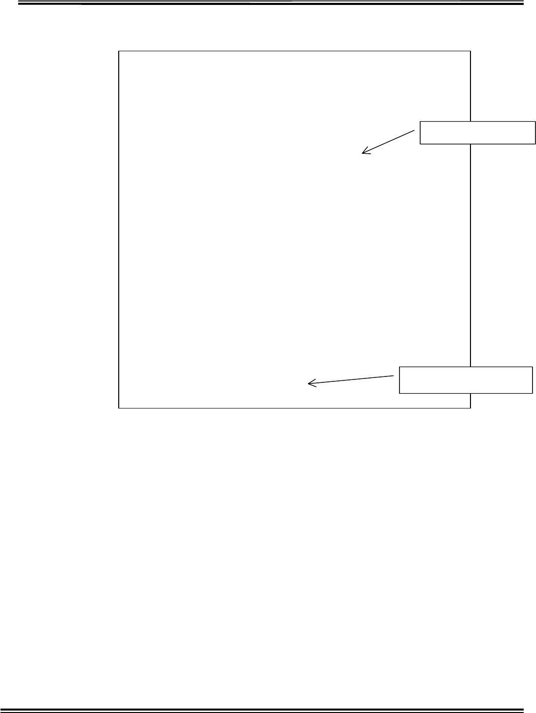
Transponder Clone Mode
Fig.4-14 CONNECTION OF CLONING UNIT
Connect the cloning unit like above chart, and start up PC and then run “Hyper
Terminal” of Windows accessory.
When TRANSPONDER turned ON, the following screen (Fig.4-15) is displayed.
Fig.4-15 Transponder set-up screen
At this point when pushing C key within 5sec, the following screen (Fig.4-16) is
displayed and Mode Set can be changed. Pushing Enter key terminates the setting.
Fig.4-16Setting for Transponder
Insert to CN2 o
f
TRANSPONDER
PC under
Windows 95 or
98
RS232C
Straight Cable
Conversion Cable
#
##### RP69W01 Ver.1.0 ######
1. Repeater Retry Qty = [3] (x10sec)
Change Mode Set = [C] ? Execute = [Enter] ?
Note: No Key, Auto Execute after 5 sec.
Current Status o
f
Transponder setting
**** << Current Mode Status >> ****
1. Repeater Retry Qty = [3] (x10sec)
**** << Mode Set >> ****
[1] = Repeater Retry Qty Set
[0] = END
Select [1],[0] and Press [Enter]
>1

RX-W1 Page 33
Setting of Transponder Re-try number of times (Select [] in Fig.4-16)
It means even the signal from Transponder is aborted, it holds IDs for re-try
number of times multiplied by 10sec.
Fig.4-17 Setting of Transponder Re-try number of times
Select [] in Fig. 4-5, and then CLONING MODE will be terminated.
After terminated CLONINGMODE, it returns to Normal Mode.
Fig.4-18 CLONINGMODE Termination
>1
Repeater Retry Qty = [3]
Repeater Retry Qty [1]-[9]x10s =4
Current Retry number of times
Retry number of times changed.
unit: [10sec]
**** << Mode Set >> ****
[1] = Repeater Retry Qty Set
[0] = END
Select [1],[0] and Press [Enter]
>0
Mode set end.
RX-W1 Page 34
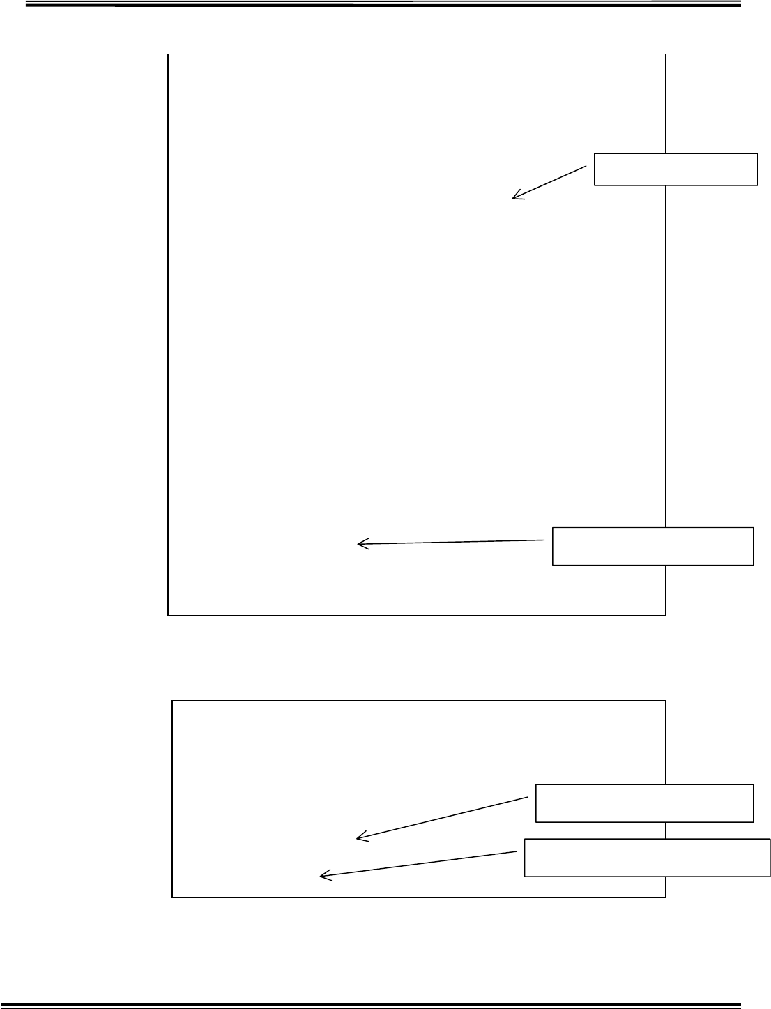
Receiver Clone Mode
Fig.4-19 CONNECTION OF CLONING UNIT
Connect the cloning unit like above chart, and start up PC and then run “Hyper
Terminal” of Windows accessory.
When Receiver turned ON, the following screen (Fig.4-20) is displayed.
Fig.4-20 Initial screen of Receiver
RECEIVER PC under
Windows 95 or
98
RS232C
Strai
g
h
t
#
##### RX69W01 Ver.1.0 ######
1. Melody Channel for Area Id
Area Id 1 = Melody [01] (Ch)
Area Id 2 = Melody [02] (Ch)
Area Id 3 = Melody [03] (Ch)
Area Id 4 = Melody [04] (Ch)
Area Id 5 = Melody [05] (Ch)
Area Id 6 = Melody [06] (Ch)
Area Id 7 = Melody [07] (Ch)
Area Id 8 = Melody [08] (Ch)
Area Id 9 = Melody [09] (Ch)
Area Id 10 = Melody [03] (Ch)
Area Id 11 = Melody [03] (Ch)
Area Id 12 = Melody [02] (Ch)
Area Id 13 = Melody [01] (Ch)
Area Id 14 = Melody [14] (Ch)
Area Id 15 = Melody [15] (Ch)
Area Id 16 = Melody [16] (Ch)
2. Melody Output = Repeat
3. Display switching time for multiple alarmed ID'S = [3]x0.5 (sec)
4. Dispaly holding time for alarmed ID = [3]x10 (sec)
Change Mode Set = [C] ? Execution = [Enter] ?
Note: No Key, Auto Execution after 5 sec.
Current Status o
f
Receiver setting
RX-W1 Page 35
At this point when pushing C key within 5sec, the following screen (Fig.4-5) is
displayed and Mode Set can be changed. Pushing Enter key terminates the setting.
Fig.4-21 Mode Set for Receiver
Setting Melody Channel for Area ID (Select [] in Fig.4-21)
Fig.4-22 Setting Melody Channel for Area ID
**** << Current Mode Status >> ****
1. Melody Channel for Area Id
Area Id 1 = Melody [01] (Ch)
Area Id 2 = Melody [02] (Ch)
Area Id 3 = Melody [03] (Ch)
Area Id 4 = Melody [04] (Ch)
Area Id 5 = Melody [05] (Ch)
Area Id 6 = Melody [06] (Ch)
Area Id 7 = Melody [07] (Ch)
Area Id 8 = Melody [08] (Ch)
Area Id 9 = Melody [09] (Ch)
Area Id 10 = Melody [03] (Ch)
Area Id 11 = Melody [03] (Ch)
Area Id 12 = Melody [02] (Ch)
Area Id 13 = Melody [01] (Ch)
Area Id 14 = Melody [14] (Ch)
Area Id 15 = Melody [15] (Ch)
Area Id 16 = Melody [16] (Ch)
2. Melody Output = Repeat
3. Display switching time for multiple alarmed ID'S = [3]x0.5 (sec)
4. Dispaly holding time for alarmed ID = [3]x10 (sec)
**** << Set of Mode >> **** Cancel=ESC
[1] = Melody Channel for Area Id
[2] = Melody Output
[3] = Display switching time for multiple alarmed IDS
[4] = Display holding time for alarmed ID
Select [1]-[4] and Press [Enter]
>1
Current Status o
f
Receiver setting
**** << Change Melody for Area Id & confirm each Melodies >> ****
Cancel=ESC
[1] = Change Melody for Area Id
[2] = Confirm each melodies
Select [1]-[2] and Press [Enter]
>1
Confirm Melody
Change Melody

RX-W1 Page 36
Change Melody for Area Id (Select [] in Fig.4-22)
Fig.4-23 Setting Melody Channel for Area ID
**** << Change Melody for Area Id >> **** Cancel=ESC
[01] = Setting Area Id 1
[02] = Setting Area Id 2
[03] = Setting Area Id 3
[04] = Setting Area Id 4
[05] = Setting Area Id 5
[06] = Setting Area Id 6
[07] = Setting Area Id 7
[08] = Setting Area Id 8
[09] = Setting Area Id 9
[10] = Setting Area Id 10
[11] = Setting Area Id 11
[12] = Setting Area Id 12
[13] = Setting Area Id 13
[14] = Setting Area Id 14
[15] = Setting Area Id 15
[16] = Setting Area Id 16
Select [01]-[16] and Press [Enter]
>01
A
rea ID for changing
RX-W1 Page 37
Change Melody for Area Id (Select [] in Fig.4-23)
Fig.4-24 Setting Melody Channel for Area ID
**** << Change Melody for Area Id >> **** Cancel=ESC
**** << Melody Name >> ****
[01] = Yankee Doodle
[02] = Oh Bury Me Not On The Lone Prairie
[03] = Oh! Susanna
[04] = Under The Spreading Chestnut Tree
[05] = Grandfathers Clock
[06] = Chitty Chitty Bang Bang
[07] = De Camptown Races
[08] = If Youre Happy And You Know It, Clap Your Hands
[09] = Mary Had A Little Lamb
[10] = Edelweiss
[11] = Bridge Over Troubled Water
[12] = I have Been Working On The Railroad
[13] = Do-Re-Mi
[14] = One Sunny Day
[15] = Aloha Oe
[16] = Battle Hymn of The Republic
[17] = Alarm
Select [01]-[17] and Press [Enter]
Area Id 1 = Melody [01] (Ch)
Melody Channel for Area Id 1 =>01
List of Melody name
Melody ID No. changed
RX-W1 Page 38
Confirm each melodies (Select [] Confirm in Fig.4-22)
Fig.4-24 Melody Confirmation
Setting of Melody Output Method (Select [] in Fig.4-21)
Fig.4-25 Melody output method Set
**** << Confirm each melodies >> **** Cancel=ESC
**** << Melody Name >> ****
[01] = Yankee Doodle
[02] = Oh Bury Me Not On The Lone Prairie
[03] = Oh! Susanna
[04] = Under The Spreading Chestnut Tree
[05] = Grandfathers Clock
[06] = Chitty Chitty Bang Bang
[07] = De Camptown Races
[08] = If Youre Happy And You Know It, Clap Your Hands
[09] = Mary Had A Little Lamb
[10] = Edelweiss
[11] = Bridge Over Troubled Water
[12] = I have Been Working On The Railroad
[13] = Do-Re-Mi
[14] = One Sunny Day
[15] = Aloha Oe
[16] = Battle Hymn of The Republic
[17] = Alarm
Select [01]-[17] and Press [Enter]
Current Melody Ch= [01]
Request Melody Ch=>01
List of Melody name
Melody number confirme
d
**** << Melody Output >> **** Cancel=ESC
[0] = One Shot
[1] = Repeat
Select [0]-[1] and Press [Enter]
Melody Output = Repeat
Melody Output =>1
Current Melody output metho
d
Melody Output method for changing
RX-W1 Page 39
Display switching time for multiple ID’s Set (Select [] in Fig.4-21)
Fig.4-26 Changing Display holding time for Multiple IDs
Display holding time for alarmed ID Set (Select [] in Fig.4-21)
Fig.4-27 Changing Display holding time
**** << Display switching time for multiple alarmed IDS >> ****
Cancel=ESC
[1] = 0.5 Sec
[2] = 1.0 Sec
[3] = 1.5 Sec
[4] = 2.0 Sec
[5] = 2.5 Sec
[6] = 3.0 Sec
[7] = 3.5 Sec
[8] = 4.0 Sec
[9] = 4.5 Sec
Select [1]-[9] and Press [Enter]
Display switching time for multiple alarmed IDS = [3]x0.5 (sec)
Display switching time for multiple alarmed IDS =>6
Current holding time for displa
y
Holding time for display change
d
**** << Display holding time for alarmed ID >> **** Cancel=ESC
[1] = 10 Sec
[2] = 20 Sec
[3] = 30 Sec
[4] = 40 Sec
[5] = 50 Sec
[6] = 60 Sec
[7] = 70 Sec
[8] = 80 Sec
[9] = 90 Sec
Select [1]-[9] and Press [Enter]
Display holding time for alarmed ID = [3]x10 (sec)
Display holding time for alarmed ID =>3
Current holding time for displa
y
Holding time for display change
d

RX-W1 Page 40
Push [Esc] in Fig. 4-21, and then CLONING MODE will be terminated.
After terminated CLONINGMODE, it returns to Normal Mode.
Fig.4-28 CLONINGMODE Termination
**** << Set of Mode >> **** Cancel=ESC
[1] = Melody Channel for Area Id
[2] = Melody Output
[3] = Display switching time for multiple alarmed IDS
[4] = Display holding time for alarmed ID
Select [1]-[4] and Press [Enter]
>
**** << End of Mode Set >> ****