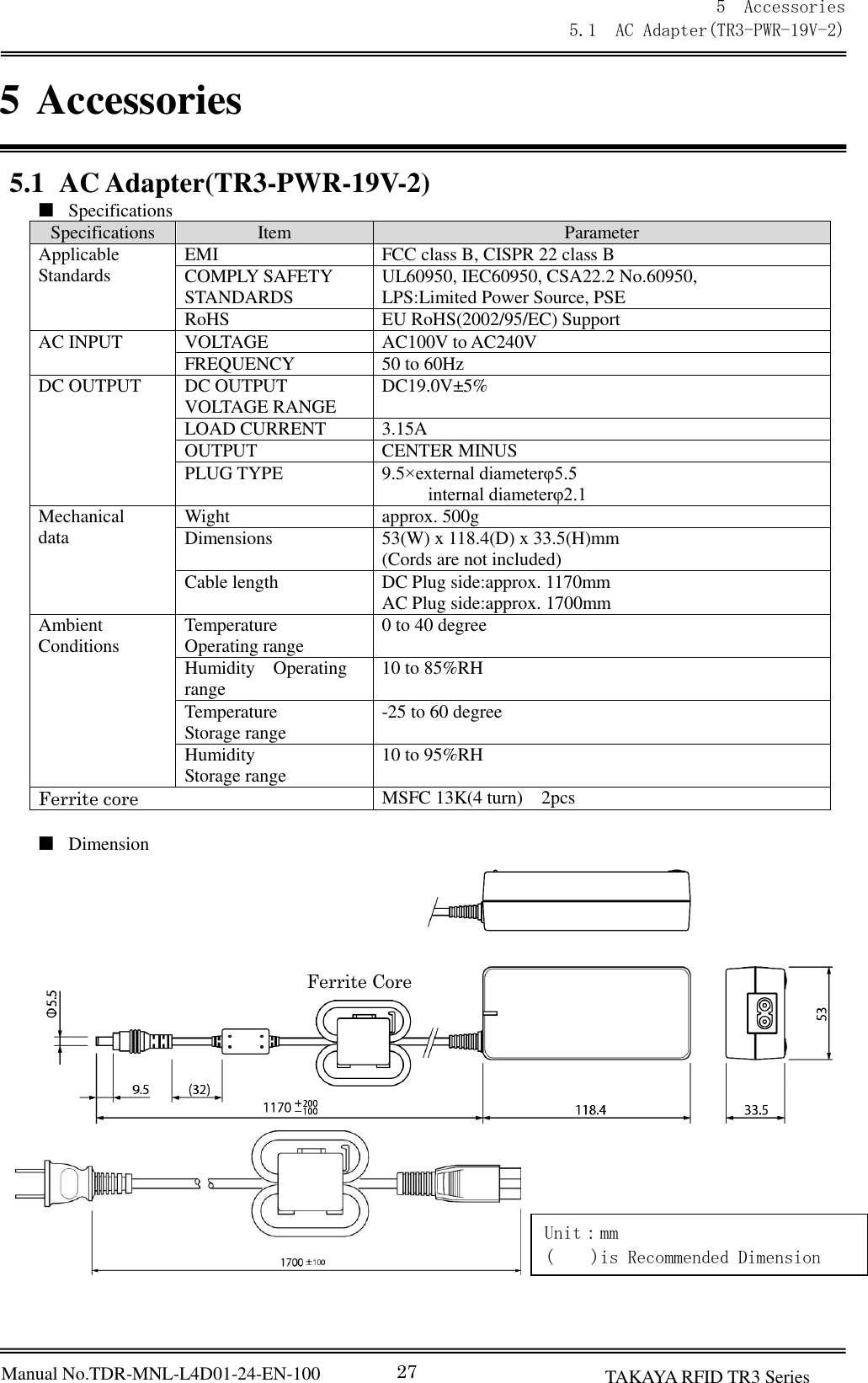
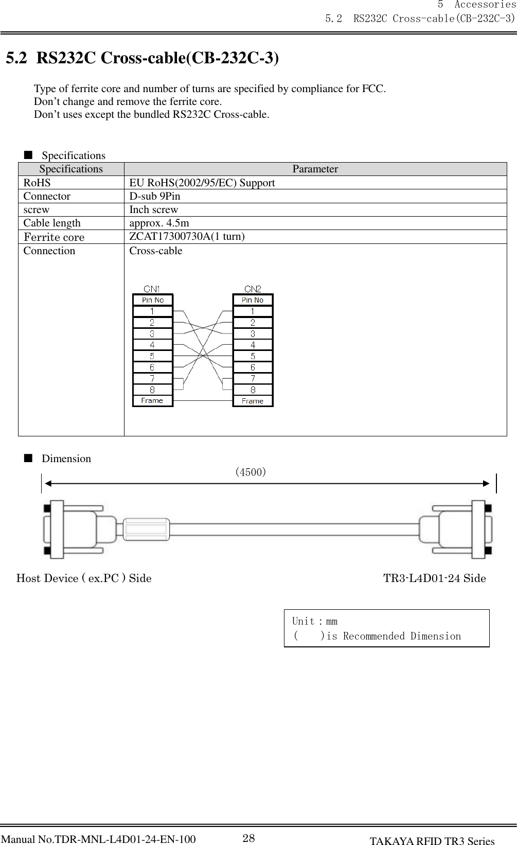
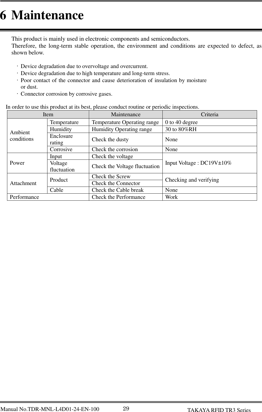
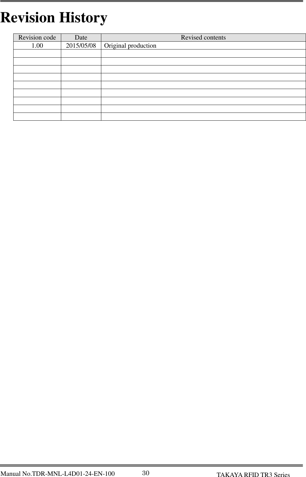
TAKAYA TR3-L4D01-24 RFID READER/WRITER User Manual Rev 2
TAKAYA Corporation RFID READER/WRITER Users Manual Rev 2
UserManual.wiki
>
TAKAYA
>
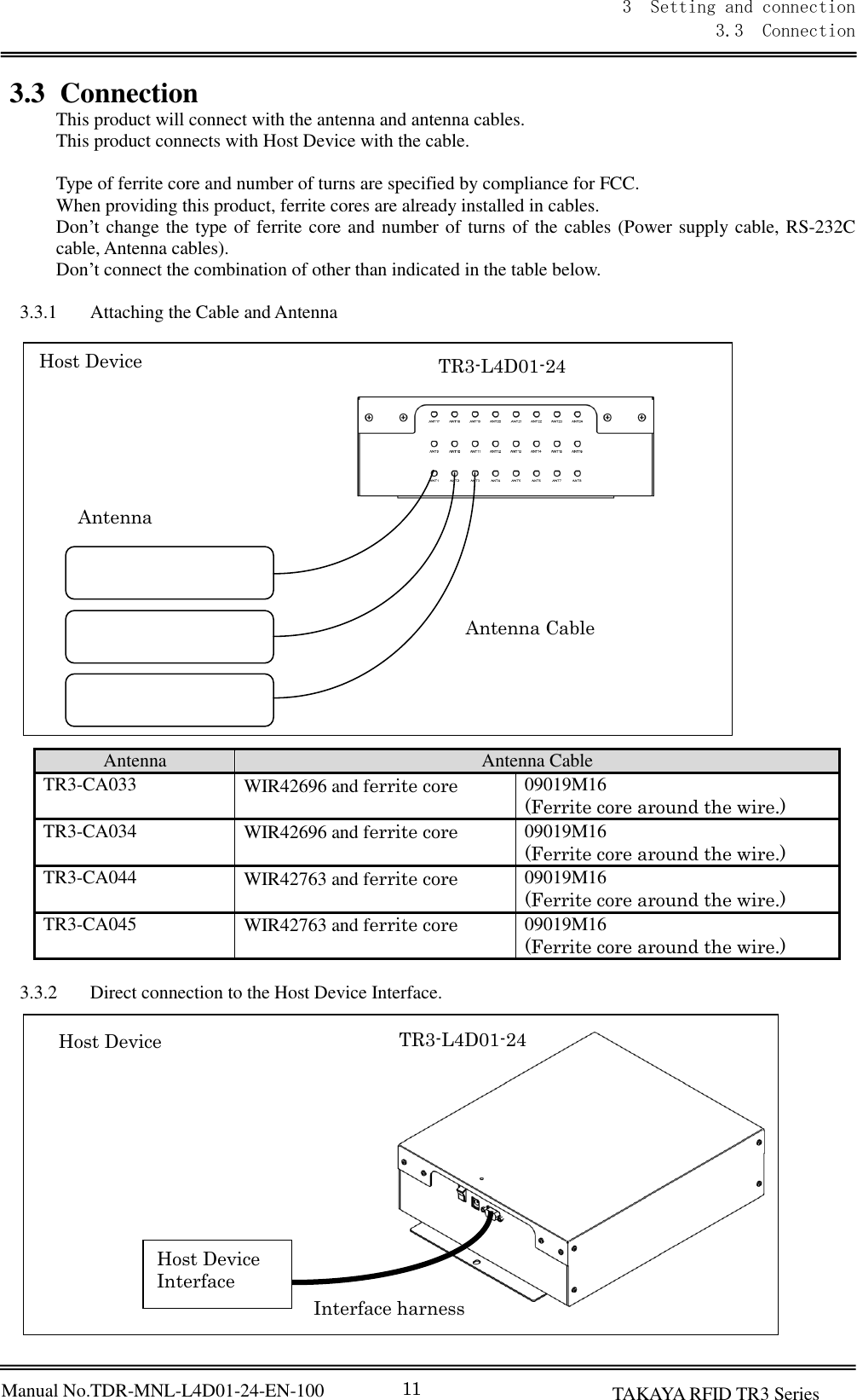
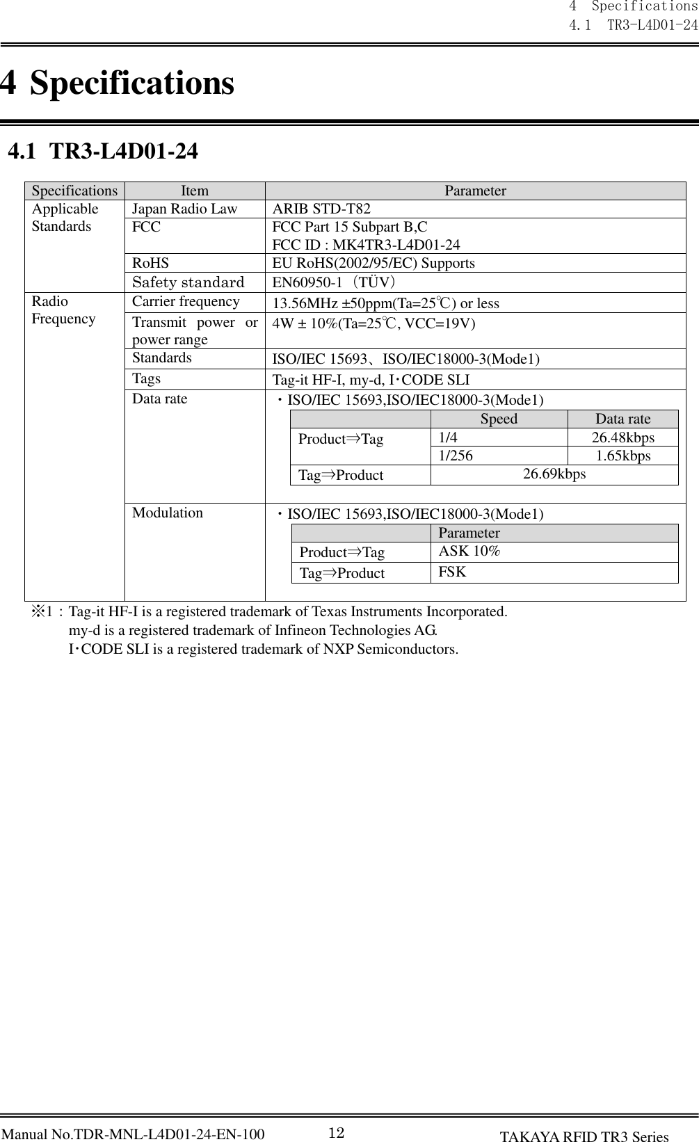
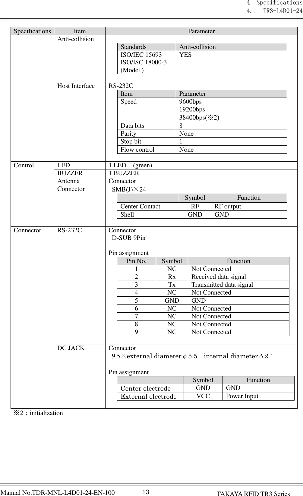
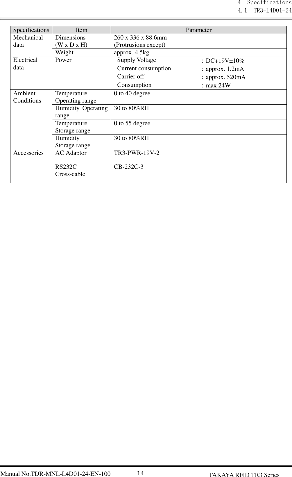
TR3 L4D01 24 User Manual
Users Manual Rev 2
Navigation menu
Upload a User Manual
Namespaces
Wiki Guide
HTML
PDF
Info
Views
User Manual
Discussion / Help
Navigation
![31 [URL] http://www.takaya.co.jp/ [Mail] rfid@takaya.co.jp](https://usermanual.wiki/TAKAYA/TR3-L4D01-24/User-Guide-2619071-Page-37.png)