TAKAYA TR3-L4D01-24 RFID READER/WRITER User Manual Rev 2
TAKAYA Corporation RFID READER/WRITER Users Manual Rev 2
TAKAYA >
Users Manual Rev 2

User’s Manual
TR3-L4D01-24
Manual No.TDR-MNL-L4D01-24-EN-100

Manual No.TDR-MNL-L4D01-24-EN-090
TAKAYA RFID TR3 Series
Introduction
Thank you for purchasing a TR3-L4D01-24 RFID READER/WRITER.
Be sure to read this manual before using the product.
After reading it, store the manual in a convenient place for future reference.

Manual No.TDR-MNL-L4D01-24-EN-090
TAKAYA RFID TR3 Series
Regulations and Standards
FCC
This product is conform to the FCC standards.
FCC Rules (Federal Communications Commission)
This product complies with Part 15 Subpart B and C of the FCC Rules.
FCC ID : MK4TR3-L4D01-24
FCC NOTICE
This equipment has been tested and found to comply with the limits for a Class B digital device,
pursuant to part 15 of the FCC Rules. These limits are designed to provide reasonable protection
against harmful interference in a residential installation. This equipment generates, uses and can
radiate radio frequency energy and, if not installed and used in accordance with the instructions,
may cause harmful interference to radio communications. However, there is no guarantee that
interference will not occur in a particular installation. If this equipment does cause harmful
interference to radio or television reception, which can be determined by turning the equipment
off and on, the user is encouraged to try to correct the interference by one or more of the following
measures:
- Reorient or relocate the receiving antenna.
- Increase the separation between the equipment and receiver.
- Connect the equipment into an outlet on a circuit different from that to which the receiver is
connected.
- Consult the dealer or an experienced radio/TV technician for help.
FCC WARNING
Changes or modifications not expressly approved by the party responsible for compliance could void
the user's authority to operate the equipment.
This equipment must be professionally installed to ensure compliance with Part 15.
Antennas not allowed are strictly prohibited for use with This equipment.
This equipment is to be professionally installed by professional service trained personnel only.
SMB sockets are provided in the equipment for connecting the external antenna.
The following sentence has to be displayed on the outside of the device in which the transmitter module
is installed : “Contains FCC ID: MK4TR3-L4D01-24”
This equipment complies with FCC radiation exposure limits set forth for an uncontrolled environment.
The antenna(s) used for this transmitter must not be collocated or operating in conjunction with any
other antenna or transmitter within a host device,
except in accordance with FCC multi-transmitter product procedures.
The final system integrator must ensure there is no instruction provided in the user manual or customer
documentation indicating how to install or remove the transmitter module except such device has
implemented two-ways authentication between module and the host system.
FCC §15.27 b) - Special Accessories –
If a device requiring special accessories is installed by or under the supervision of the party marketing
the device, it is the responsibility of that party to install the equipm ent using the special accessories.
For equipment requiring professional installation, it is not necessary for the responsible party to market
the special accessories with the equipment.
However, the need to use the special accessories m ust be detailed in the instruction manual, and it is
the responsibility of the installer to provide and to install the required accessories.

Manual No.TDR-MNL-L4D01-24-EN-090
TAKAYA RFID TR3 Series
Japan Radio Law
Equipment using high frequencies: Inductive Reading/Writing Communications Equipment
Conforming standards: Inductive Reading/Writing Communications Equipment;
Standard: ARIB STD-T82
RoHS is support
Restriction of Hazardous Substances
Waste
Dispose of the Products as industrial waste.
Manual No.TDR-MNL-L4D01-24-EN-090
TAKAYA RFID TR3 Series
Safety Precautions
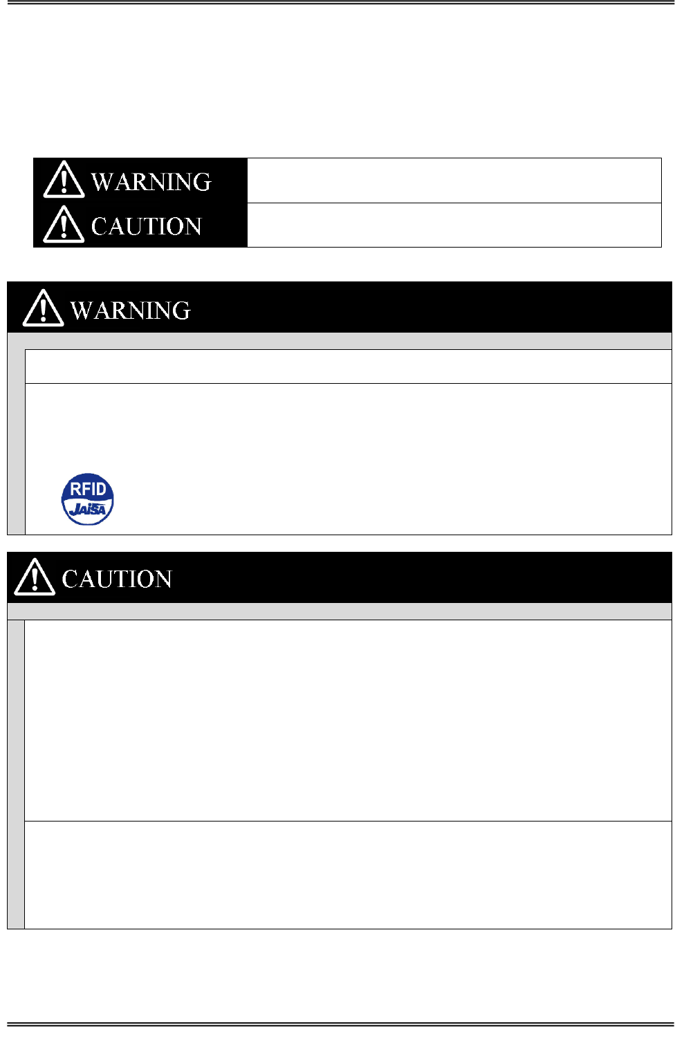
The following symbols are used in this manual to indicate precautions that must be observed to ensure safe use of
this product. The precautions provided here contain important safety information. Be sure to observe these
precautions.
The following signal words are used in this manual.
Failure to comply with a WARNING may result in serious injury or
death.
Failure to comply with a CAUTION may result in injury to the
operator, or damage to the items involved.
Be sure to observe the following precautions to ensure safe use of the Products.
Decomposition of this product and cable, repair, remodeling, please strictly prohibited. There is the
possibility of fire or electric shock injuries.
This product is using the RFID reader writer radio equipment. Therefore, depending on where the
applications you use may affect medical equipment. To minimize the impact of medical equipment for use,
please observe the following countermeasure. The Japan Automatic Identification Systems Association
(JAISA) guidelines are as follows: RFID antennas from implanted cardiac pacemakers or other medical
devices please 22cm apart. We recommend that you paste "RFID sticker" at equipment.
Be sure to observe the following precautions to ensure safe use of the Products.
Installation and storage environment
1. Do not use the Products in sunlight.
2. Do not use the Products in environment of spray of water, oil or chemicals.
3. Do not use the Products in environments with flammable, explosive, or corrosive gasses.
4. Do not use the Products in environment of hot humid.
5. Do not use the Products in environment of vibration or shock.
6. Do not use the Products in environment of condensation.
7. Do not use the Products in environment of around the metal is covered.
8. Do not use the Products in environment of high temperature.
9. Do not use the Products in environment that has a device that generates magnetic field and shock voltage.
10. Do not use the Products in unstable place.
11. If there is failure, discontinue use immediately, please contact us or the distributor.
Installation
1. Turn off the power before installation or removing.
2. The following effects may not work correctly.
・ Near 13.56MHz radio device
・ Near speakers , Inverter, motor and Plasma Display
3. The communication range may vary due to environment and conditions.
← RFID Sticker

Manual No.TDR-MNL-L4D01-24-EN-090
TAKAYA RFID TR3 Series
Contents
1 Product Overview ...................................................................................................... 1
1.1 Features .............................................................................................................................................. 1
2 Names of Parts and Functions ..................................................................................... 2
2.1 TR3-L4D01-24 .................................................................................................................................... 2
2.2 Antenna .............................................................................................................................................. 4
3 Setting and connection ................................................................................................ 8
3.1 Setting ................................................................................................................................................. 8
3.1.1 DeskTop ........................................................................................................................................... 8
3.1.2 Wall Mounting .................................................................................................................................. 8
3.2 Antenna installation into a host device ................................................................................................. 9
3.2.1 Installation example by Screw holes ................................................................................................... 9
3.3 Connection ......................................................................................................................................... 11
3.3.1 Attaching the Cable and Antenna ....................................................................................................... 11
3.3.2 Direct connection to the Host Device Interface. .................................................................................. 11
4 Specifications ........................................................................................................... 12
4.1 TR3-L4D01-24 .................................................................................................................................. 12
4.2 Antenna ............................................................................................................................................ 16
4.2.1 TR3-CA033 .................................................................................................................................... 16
4.2.2 TR3-CA034 .................................................................................................................................... 18
4.2.3 TR3-CA044 .................................................................................................................................... 20
4.2.4 TR3-CA045 .................................................................................................................................... 22
4.3 Coupler Cable ................................................................................................................................... 24
4.4 Antenna Cable................................................................................................................................... 25
4.4.1 WIR42696 ...................................................................................................................................... 25
4.4.2 WIR42763 ...................................................................................................................................... 25
4.4.3 09019M16 ...................................................................................................................................... 26
5 Accessories .............................................................................................................. 27
5.1 AC Adapter(TR3-PWR-19V-2) .......................................................................................................... 27
5.2 RS232C Cross-cable(CB-232C-3) ...................................................................................................... 28
6 Maintenance ............................................................................................................ 29
Revision History ............................................................................................................. 30
Manual No.TDR-MNL-L4D01-24-EN-100
1 Product Overview
1.1 Features
1
TAKAYA RFID TR3 Series
1 Product Overview
1.1 Features
This product uses the 13.56MHz frequency. This product is the electromagnetic induction type non-contact
IC can read and write RFID tag data.
This Product is designed to be embedded and integrated within OEM devices and finished products such as label
printers, cashless payment terminals or any other device that can benefit from integrated RFID capabilities.
■ Conform to international standards
ISO/IEC15693 and ISO/IEC18000-3(Mode1) is supports.
■ Software
TR3-series common communication protocol
Software Development Kit
■ Multiplexer
Select the RF output.
■ Useful
Continuous inventory mode
UID of the tag automatically sends Host Device.
RDLoop mode
UID or User Data of the tag automatically sends Host Device.
For more information please refer to the TR3-PROTOCOL manual.
■ Environmentally
EU RoHS(2002/95/EC) Support
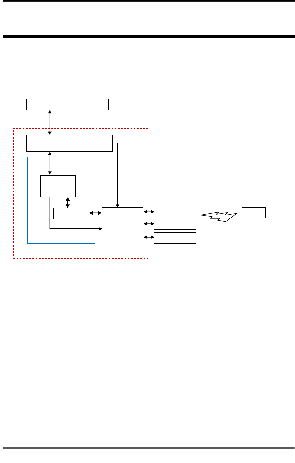
Antenna
CPU
RF-ASIC
TR3-L201W4(READER/WRITER)
Module)
LED/BUZZER
Interface Module
Tags
Host Device Interface
RS-232C
Communications
UART(CMOS Level)
TR3-L4D01-24
Block Diagram
Host Device Interface
Multiplexer
Antenna
Antenna
Manual No.TDR-MNL-L4D01-24-EN-100
2 Names of Parts and Functions
2.1 TR3-L4D01-24
2
TAKAYA RFID TR3 Series
2 Names of Parts and Functions
2.1 TR3-L4D01-24
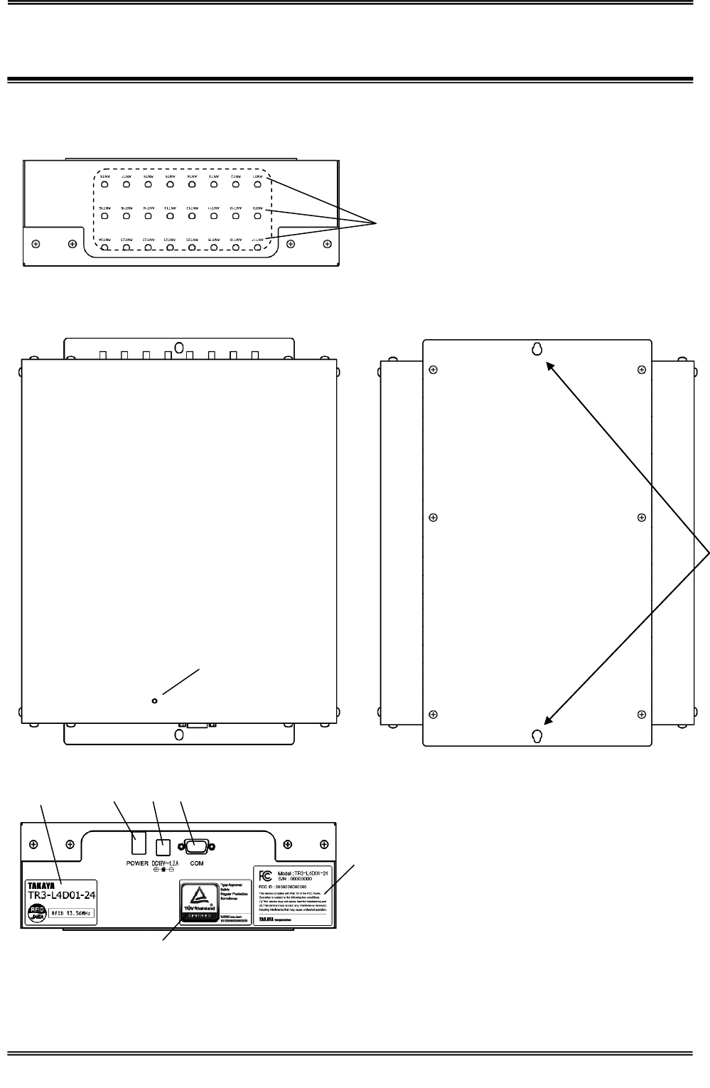
⑨
①
②
⑥
④
⑤
⑦
⑨
③

Manual No.TDR-MNL-L4D01-24-EN-100
2 Names of Parts and Functions
2.1 TR3-L4D01-24
3
TAKAYA RFID TR3 Series
No
Name
Description
①
LED
Displays the status of this product.
②
Nameplate
RFID sticker
Production numbers.
Specify that the RFID radio waves are radiated.
③
ANT1 to ANT24
Connect the Antenna cable.
Please connect from ANT1.
④
Power Button
Power ON/OFF.
⑤
DC Jack
DC +19V input.
⑥
Connector
Connect the RS-232C cable.
⑦
FCC ID sticker
Production numbers, will be 8-digit serial number.
⑧
TÜV mark
TÜV certification mark
⑨
Screw holes
6.5mm×13mm mounting holes.
Model Name
Serial number:********
Manual No.TDR-MNL-L4D01-24-EN-100
2 Names of Parts and Functions
2.2 Antenna
4
TAKAYA RFID TR3 Series
2.2 Antenna
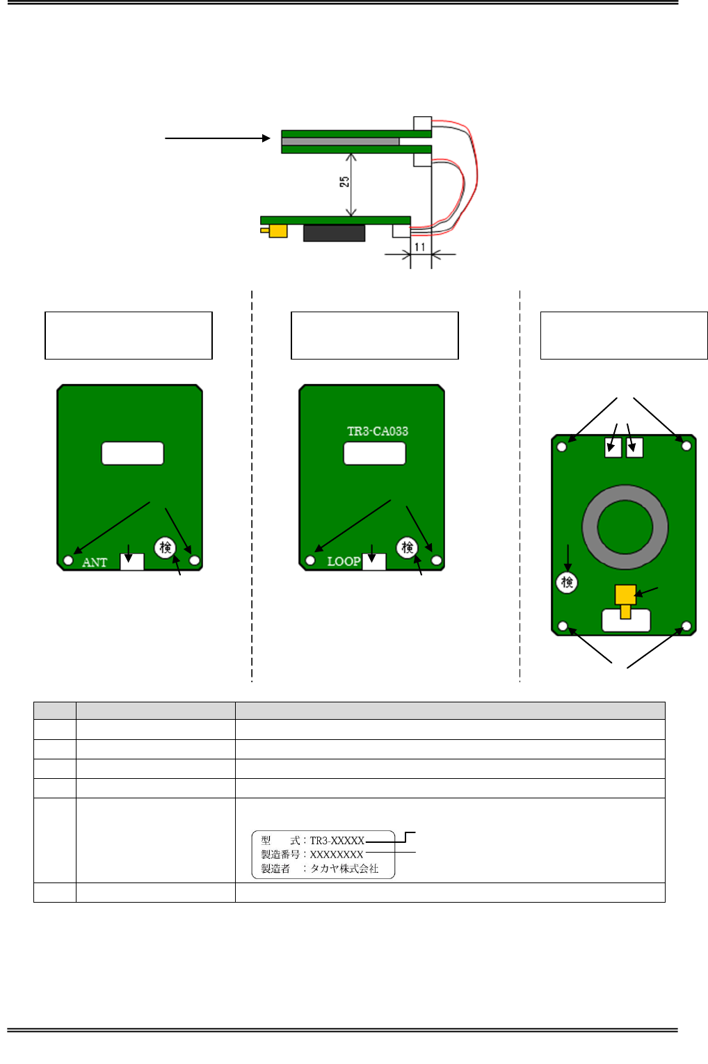
2.2.1 TR3-CA033
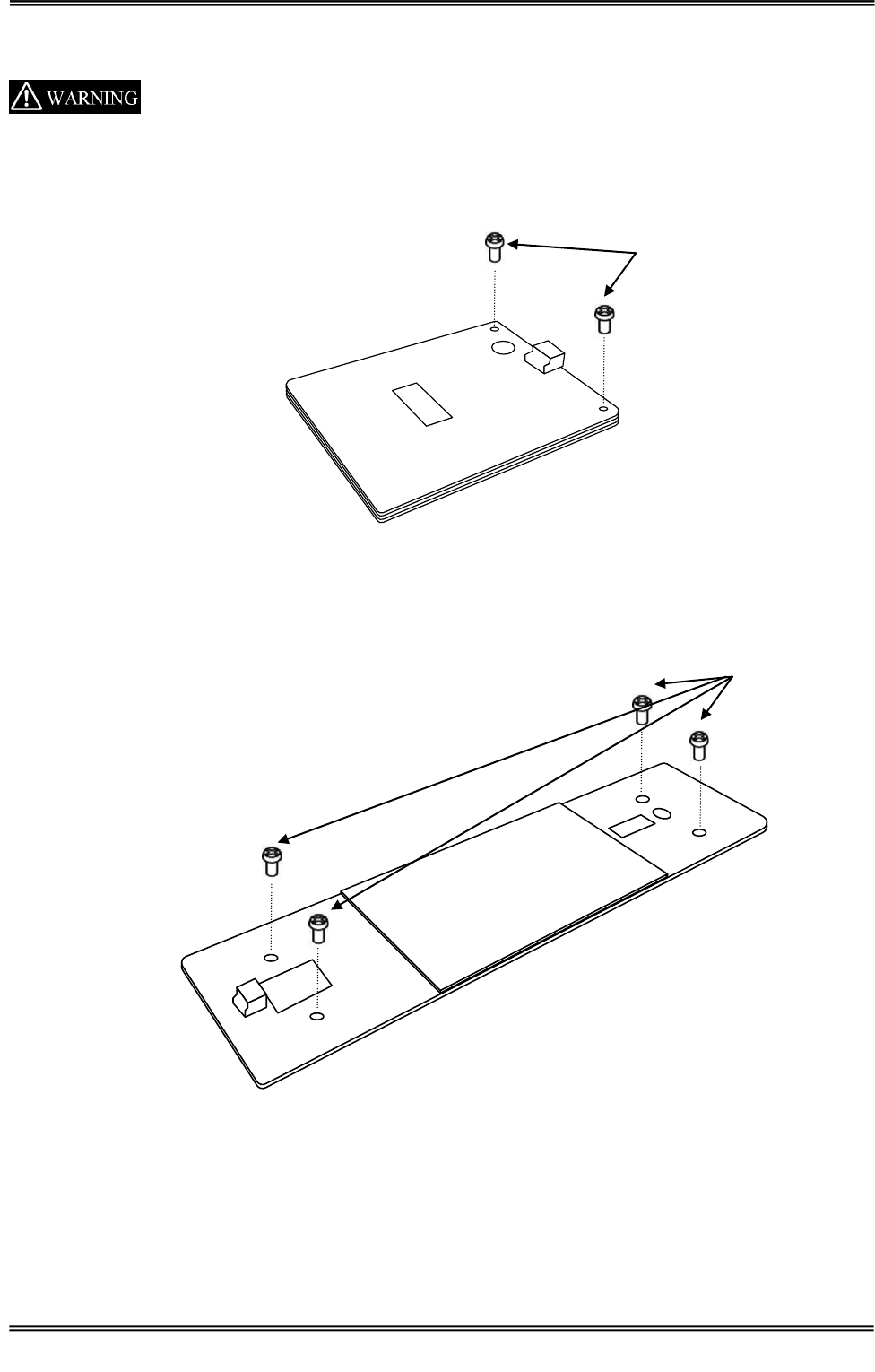
CA033 is combined by 2 loop sub antennas and a coupler board.
No
Name
Description
①
Screw holes
M3 holes.
②
CN (PH)
Connect the coupler board.
③
CN (SMA)
Connect the antenna cable.
④
ferrite sheet
Paste on TR3-CA033-1 reverse side.
⑤
Nameplate
Production numbers, will be 8-digit serial number.
⑥
Inspection mark
Sub Antenna 1
TR3-CA033-1
Sub Antenna 2
TR3-CA033-2
Coupler Board
09019P04
①
①
①
①
②
②
②
③
④
⑤
⑤
⑤
⑥
⑥
⑥
Model Name
Serial number:********
Manual No.TDR-MNL-L4D01-24-EN-100
2 Names of Parts and Functions
2.2 Antenna
5
TAKAYA RFID TR3 Series
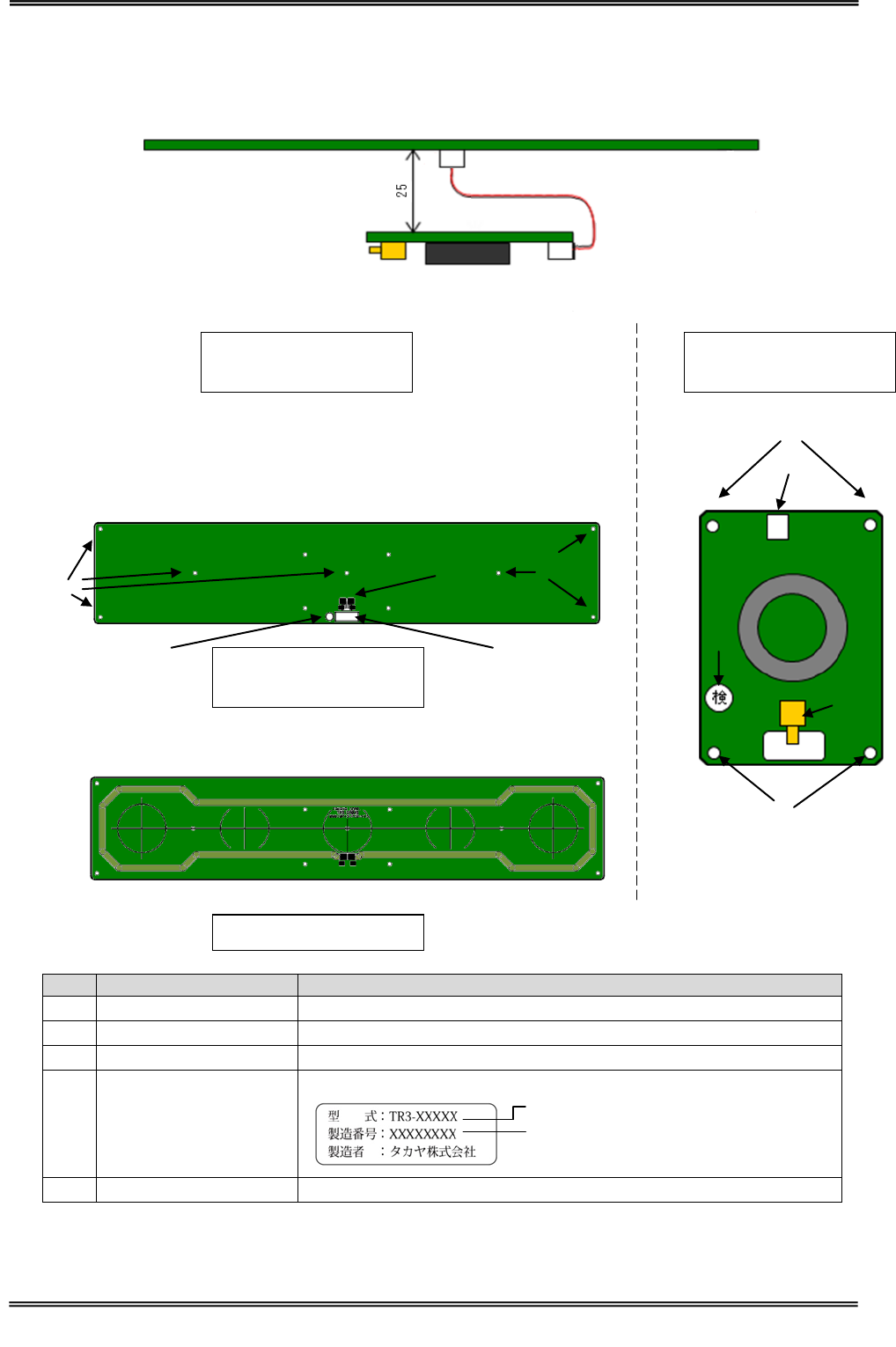
2.2.2 TR3-CA034
TR3-CA034 is combined by loop antenna and a coupler board.
No
Name
Description
①
Screw holes
M3 holes.
②
CN (PH)
Connect the coupler board.
③
CN (SMA)
Connect the antenna cable.
④
ferrite sheet
Paste on TR3-CA034 surface side.
⑤
Nameplate
Production numbers, will be 8-digit serial number.
⑥
Inspection mark
Antenna
TR3-CA034
Coupler board
09019P05
①
①
②
③
⑤
④
⑥
①
①
⑤
⑥
②
Model Name
Serial number:********
Antenna
TR3-CA034
Reverse side
Manual No.TDR-MNL-L4D01-24-EN-100
2 Names of Parts and Functions
2.2 Antenna
6
TAKAYA RFID TR3 Series
2.2.3 TR3-CA044
TR3-CA044 is combined by loop antenna and a coupler board.
No
Name
Description
①
Screw holes
M3 holes.
②
CN (PH)
Connect the coupler board.
③
CN (SMA)
Connect the antenna cable.
④
Nameplate
Production numbers, will be 8-digit serial number.
⑤
Inspection mark
Antenna
TR3-CA044
Coupler board
09019P16
①
①
②
③
④
④
⑤
①
②
⑤
Antenna
TR3-CA044
Reverse side
①
Model Name
Serial number:********
Manual No.TDR-MNL-L4D01-24-EN-100
2 Names of Parts and Functions
2.2 Antenna
7
TAKAYA RFID TR3 Series
2.2.4 TR3-CA045
TR3-CA045 is combined by loop antenna and a coupler board.
No
Name
Description
①
Screw holes
M3 holes.
②
CN (PH)
Connect the coupler board.
③
CN (SMA)
Connect the antenna cable.
④
Nameplate
Production numbers, will be 8-digit serial number.
⑤
Inspection mark
Antenna
TR3-CA045
Coupler board
09019P14
①
①
②
③
④
④
⑤
①
②
⑤
Antenna
TR3-CA045
Reverse side
①
Model Name
Serial number:********
Manual No.TDR-MNL-L4D01-24-EN-100
3 Setting and connection
3.1 Setting
8
TAKAYA RFID TR3 Series
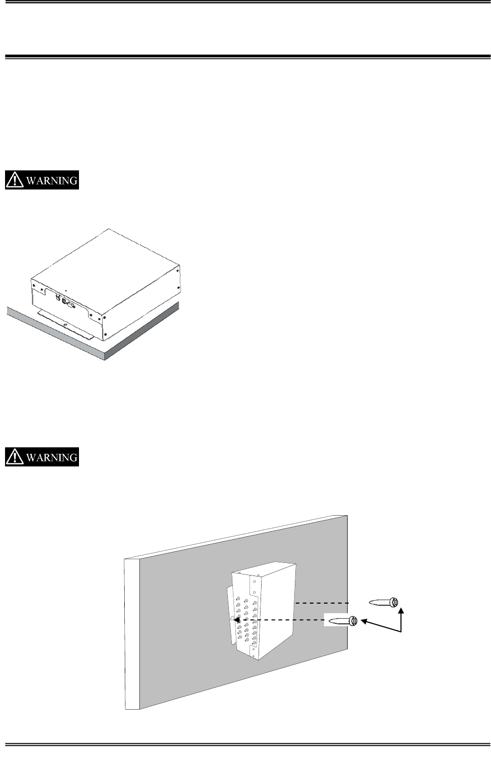
3 Setting and connection
This RFID Reader/Writer product is to be professionally installed by authorized,
qualified and service-trained installation personnel only.
3.1 Setting
3.1.1 DeskTop
Don’t drop the product. . Injury may result if the product falls or is dropped.
3.1.2 Wall Mounting
Must be fastened securely the product with the screws.
Don’t install to the high place. Injury may result if the product falls or is dropped.
Screw
Manual No.TDR-MNL-L4D01-24-EN-100
3 Setting and connection
3.2 Antenna installation into a host device
9
TAKAYA RFID TR3 Series
3.2 Antenna installation into a host device
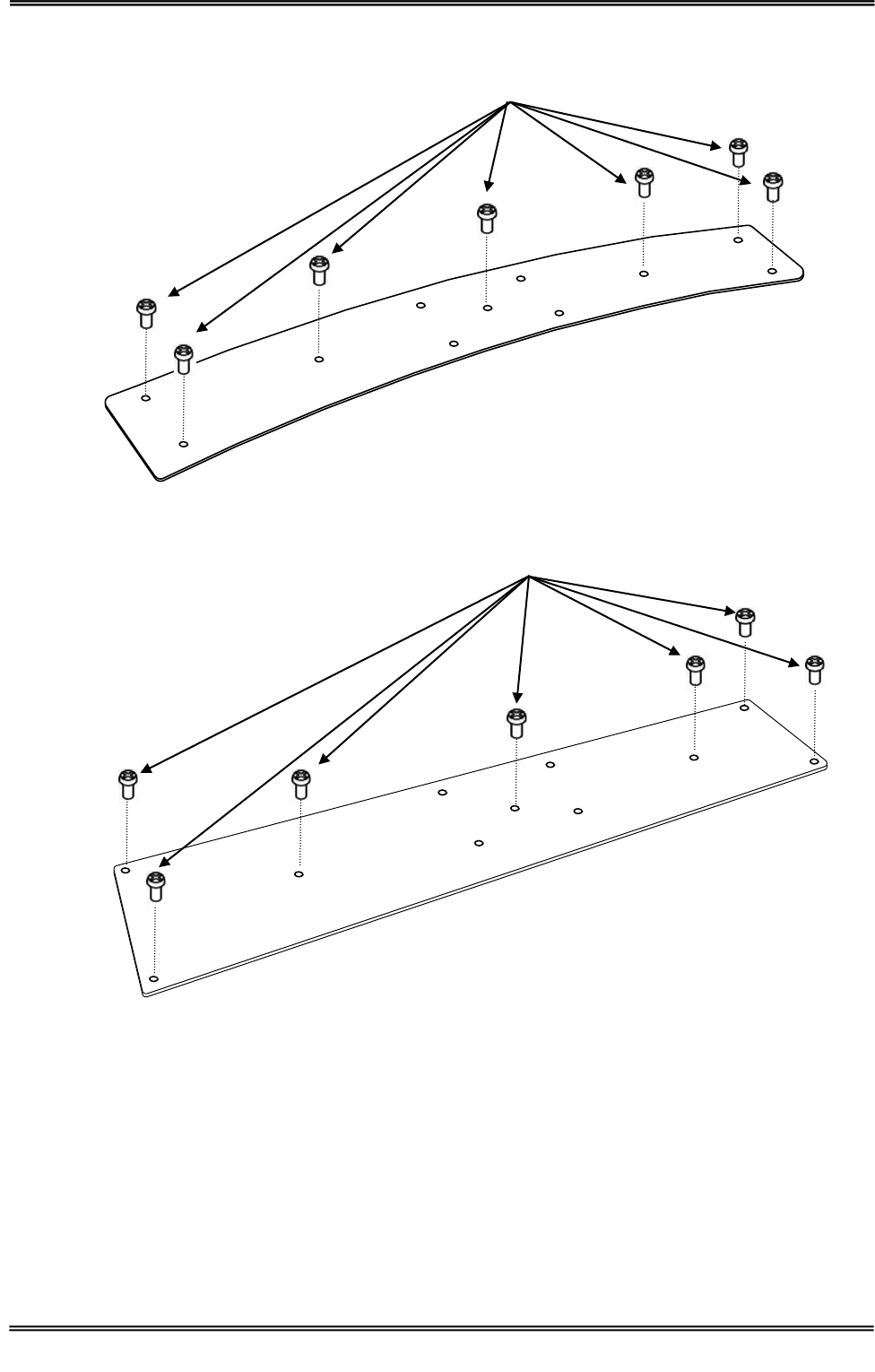
Incorporate the antenna in enclosure by all means.
3.2.1 Installation example by Screw holes
・TR3-CA033
・TR3-CA034
M3 Screw
M3 Screw
Manual No.TDR-MNL-L4D01-24-EN-100
3 Setting and connection
3.2 Antenna installation into a host device
10
TAKAYA RFID TR3 Series
・TR3-CA044
・TR3-CA045
M3 Screw
M3 Screw
Manual No.TDR-MNL-L4D01-24-EN-100
3 Setting and connection
3.3 Connection
11
TAKAYA RFID TR3 Series
3.3 Connection
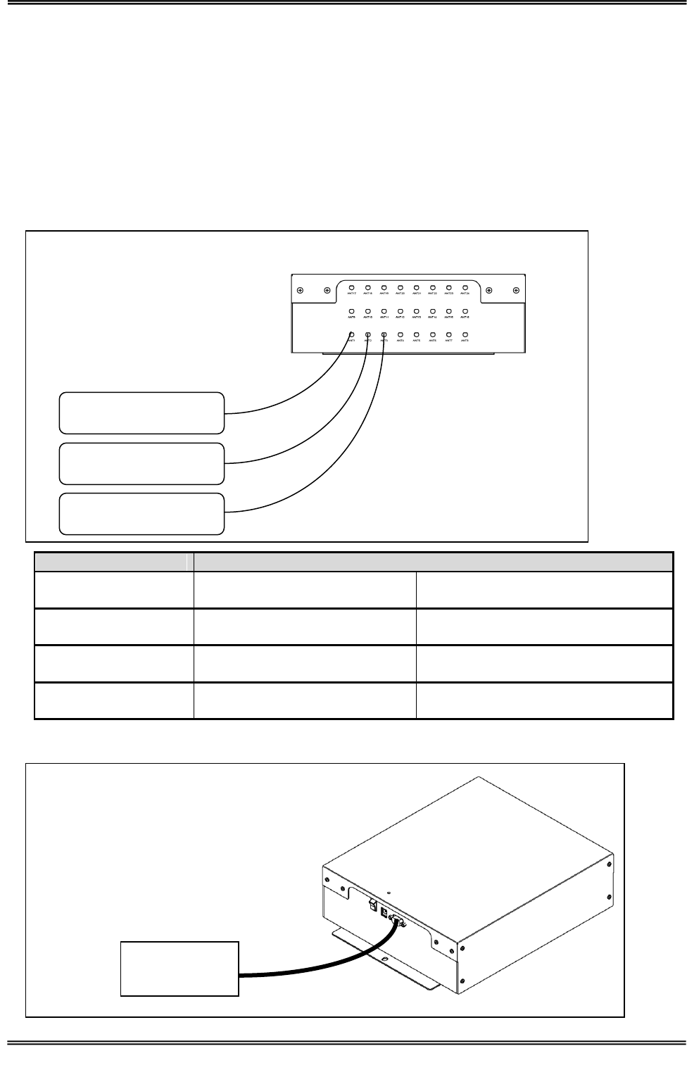
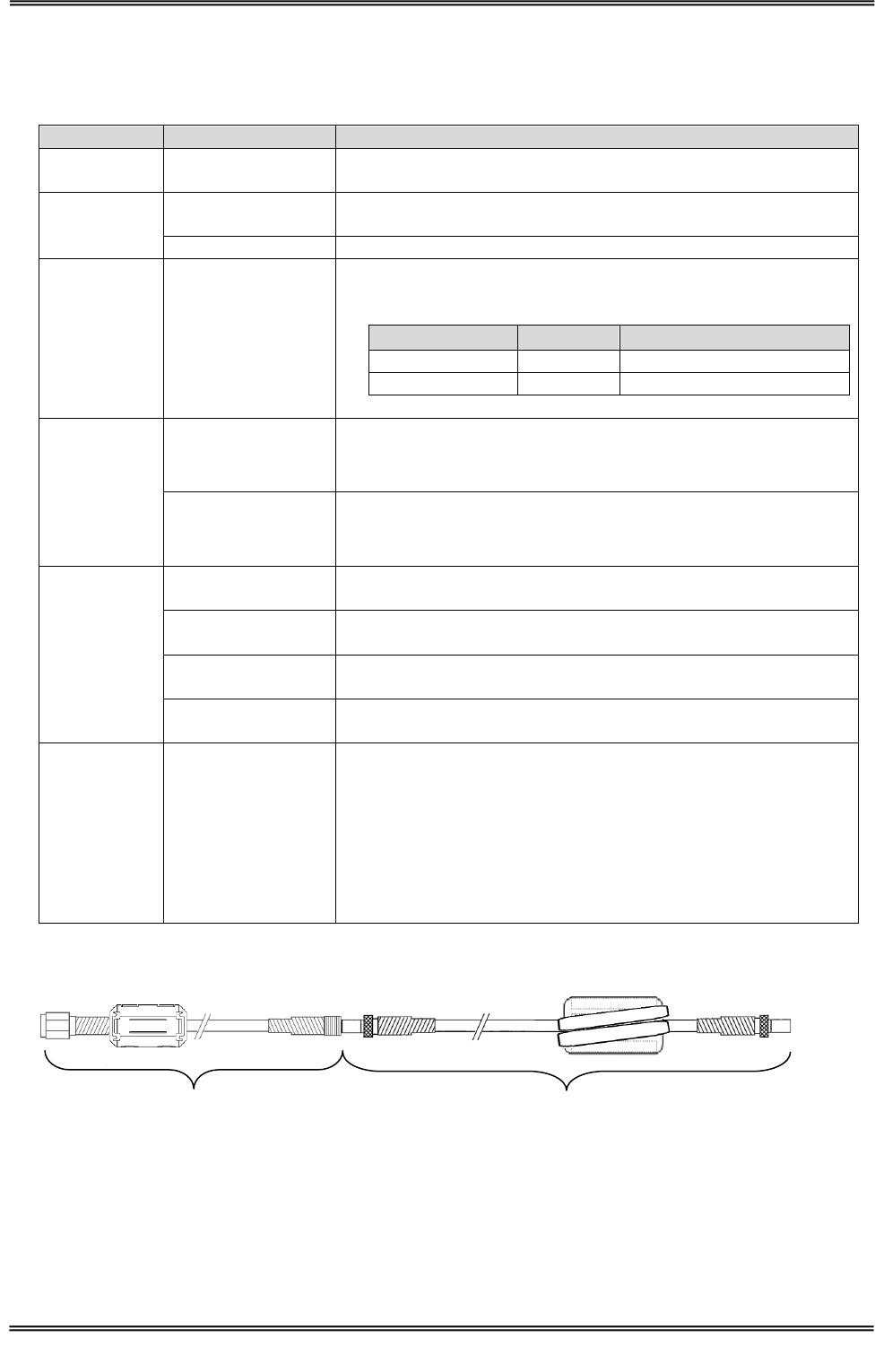
This product will connect with the antenna and antenna cables.
This product connects with Host Device with the cable.
Type of ferrite core and number of turns are specified by compliance for FCC.
When providing this product, ferrite cores are already installed in cables.
Don’t change the type of ferrite core and number of turns of the cables (Power supply cable, RS-232C
cable, Antenna cables).
Don’t connect the combination of other than indicated in the table below.
3.3.1 Attaching the Cable and Antenna
Antenna
Antenna Cable
TR3-CA033
WIR42696 and ferrite core
09019M16
(Ferrite core around the wire.)
TR3-CA034
WIR42696 and ferrite core
09019M16
(Ferrite core around the wire.)
TR3-CA044
WIR42763 and ferrite core
09019M16
(Ferrite core around the wire.)
TR3-CA045
WIR42763 and ferrite core
09019M16
(Ferrite core around the wire.)
3.3.2 Direct connection to the Host Device Interface.
TR3-L4D01-24
Antenna
Antenna Cable
Host Device
Host Device
Interface
Host Device
Interface harness
TR3-L4D01-24
Manual No.TDR-MNL-L4D01-24-EN-100
4 Specifications
4.1 TR3-L4D01-24
12
TAKAYA RFID TR3 Series
4 Specifications
4.1 TR3-L4D01-24
Specifications
Item
Parameter
Applicable
Standards
Japan Radio Law
ARIB STD-T82
FCC
FCC Part 15 Subpart B,C
FCC ID : MK4TR3-L4D01-24
RoHS
EU RoHS(2002/95/EC) Supports
Safety standard
EN60950-1(TÜV)
Radio
Frequency
Carrier frequency
13.56MHz ±50ppm(Ta=25℃) or less
Transmit power or
power range
4W ± 10%(Ta=25℃, VCC=19V)
Standards
ISO/IEC 15693、ISO/IEC18000-3(Mode1)
Tags
Tag-it HF-I, my-d, I・CODE SLI
Data rate
・ISO/IEC 15693,ISO/IEC18000-3(Mode1)
Speed
Data rate
Product⇒Tag
1/4
26.48kbps
1/256
1.65kbps
Tag⇒Product
26.69kbps
Modulation
・ISO/IEC 15693,ISO/IEC18000-3(Mode1)
Parameter
Product⇒Tag
ASK 10%
Tag⇒Product
FSK
※1:Tag-it HF-I is a registered trademark of Texas Instruments Incorporated.
my-d is a registered trademark of Infineon Technologies AG.
I・CODE SLI is a registered trademark of NXP Semiconductors.
Manual No.TDR-MNL-L4D01-24-EN-100
4 Specifications
4.1 TR3-L4D01-24
13
TAKAYA RFID TR3 Series
Specifications
Item
Parameter
Anti-collision
Standards
Anti-collision
ISO/IEC 15693
ISO/ISC 18000-3
(Mode1)
YES
Host Interface
RS-232C
Item
Parameter
Speed
9600bps
19200bps
38400bps(※2)
Data bits
8
Parity
None
Stop bit
1
Flow control
None
Control
LED
1 LED (green)
BUZZER
1 BUZZER
Antenna
Connector
Connector
SMB(J)×24
Symbol
Function
Center Contact
RF
RF output
Shell
GND
GND
Connector
RS-232C
Connector
D-SUB 9Pin
Pin assignment
Pin No.
Symbol
Function
1
NC
Not Connected
2
Rx
Received data signal
3
Tx
Transmitted data signal
4
NC
Not Connected
5
GND
GND
6
NC
Not Connected
7
NC
Not Connected
8
NC
Not Connected
9
NC
Not Connected
DC JACK
Connector
9.5×external diameterφ5.5 internal diameterφ2.1
Pin assignment
Symbol
Function
Center electrode
GND
GND
External electrode
VCC
Power Input
※2:initialization

Manual No.TDR-MNL-L4D01-24-EN-100
4 Specifications
4.1 TR3-L4D01-24
14
TAKAYA RFID TR3 Series
Specifications
Item
Parameter
Mechanical
data
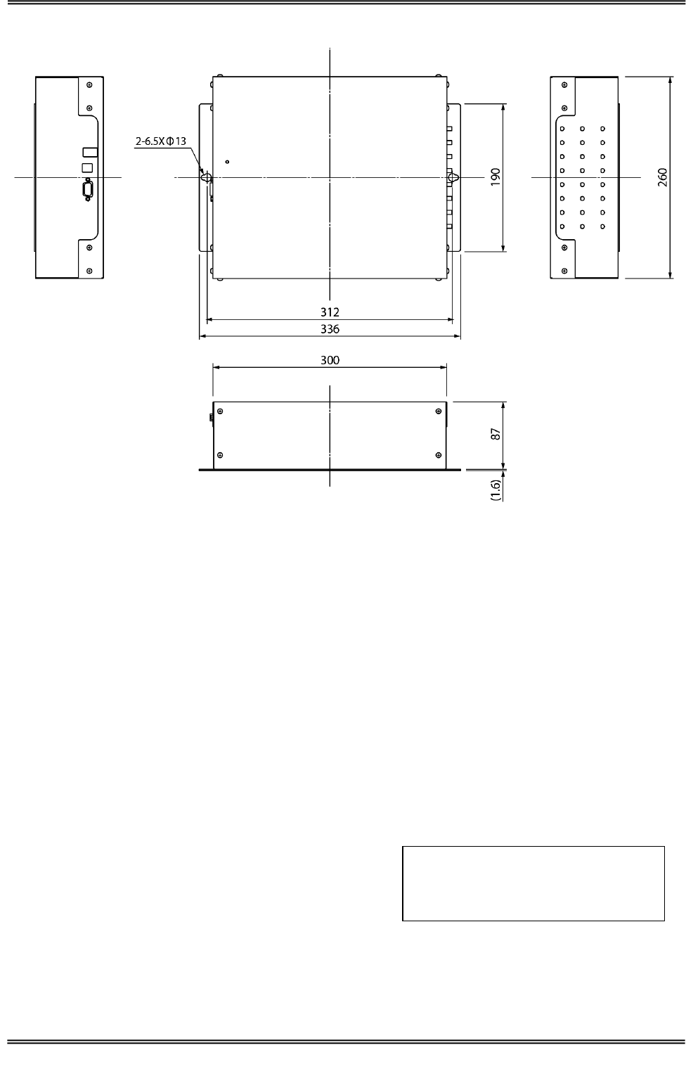
Dimensions
(W x D x H)
260 x 336 x 88.6mm
(Protrusions except)
Weight
approx. 4.5kg
Electrical
data
Power
Supply Voltage
:DC+19V±10%
Current consumption
:approx. 1.2mA
Carrier off
:approx. 520mA
Consumption
:max 24W
Ambient
Conditions
Temperature
Operating range
0 to 40 degree
Humidity Operating
range
30 to 80%RH
Temperature
Storage range
0 to 55 degree
Humidity
Storage range
30 to 80%RH
Accessories
AC Adaptor
TR3-PWR-19V-2
RS232C
Cross-cable
CB-232C-3
Manual No.TDR-MNL-L4D01-24-EN-100
4 Specifications
4.1 TR3-L4D01-24
15
TAKAYA RFID TR3 Series
■ Dimensions
Unit:mm
Tolerance:±1.0mm
( )is Recommended Dimension
Manual No.TDR-MNL-L4D01-24-EN-100
4 Specifications
4.2 Antenna
16
TAKAYA RFID TR3 Series
4.2 Antenna
4.2.1 TR3-CA033
■ Specifications
Specifications
Item
Parameter
Applicable
Standards
RoHS
EU RoHS(2002/95/EC) Support
Antenna
Resonant
frequency
13.56MHz(Ta=25℃)
Antenna Type
LOOP ANTENNA
Connector
CN1
Connector : SMA(J)
Pin assignment
Symbol
Function
Center Contact
RF
RF input
Shell
GND
GND
Mechanical
data
Dimensions
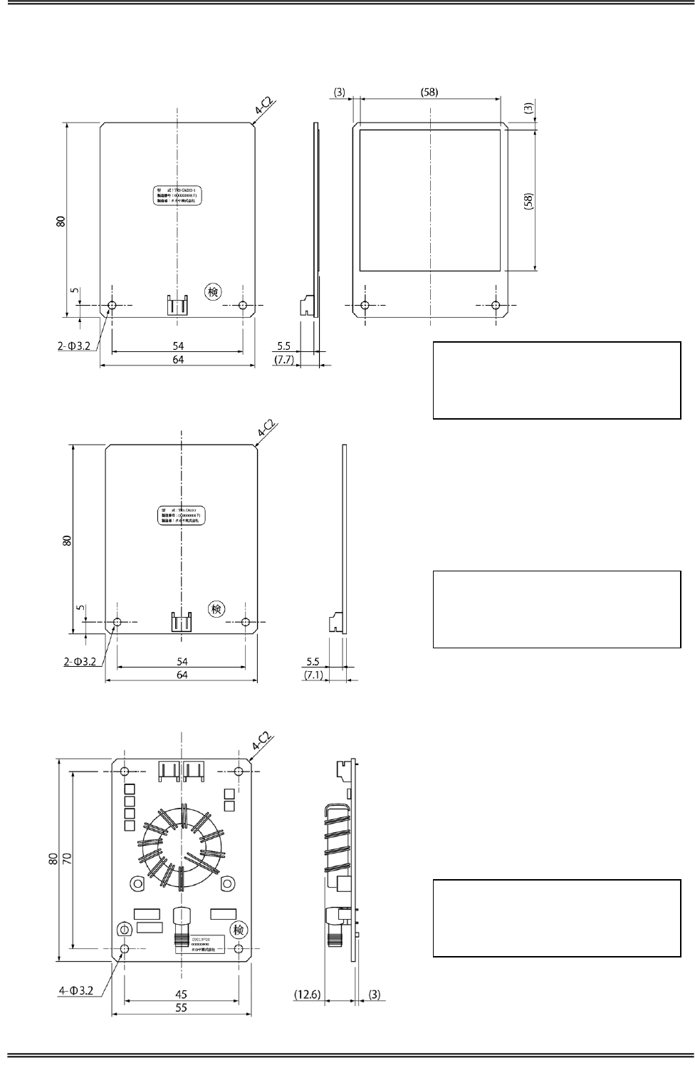
(W x D x H)
TR3-CA033-1:64 (W)×80(D)×7.7(H)mm
TR3-CA033-2:64 (W)×80(D)×7.1(H)mm
09019P04:55 (W)×80(D)×15.6(H)mm
Weight
TR3-CA033-1:25g
TR3-CA033-2:17g
09019P04:47g
Ambient
Conditions
Temperature
Operating range
0 to 40 degree
Humidity Operating
range
30 to 80%RH
Temperature
Storage range
0 to 55 degree
Humidity
Storage range
30 to 80%RH
Other
Accessories
Two Twisted pare cables
Model Name : TR3-AC-1A-120
①1.5D-2V SMA(P)-SMB(J) + Ferrite core
Model Name : WIR42696 + ZCAT13250530A(1 turn)
②1.5D-2V SMB(P)-SMB(P) + Ferrite core
Model Name : 09019M16 ( E04SR0200935A (3 turn))
①
②
Manual No.TDR-MNL-L4D01-24-EN-100
4 Specifications
4.2 Antenna
17
TAKAYA RFID TR3 Series
■ Dimensions
○TR3-CA033-1
○TR3-CA033-2
○09019P04
Unit:mm
Tolerance:±1mm
Substrate thickness : 1.6mm
Unit:mm
Tolerance:±1mm
Substrate thickness : 1.6mm
Unit:mm
Tolerance:±1mm
Substrate thickness : 1.6mm
Manual No.TDR-MNL-L4D01-24-EN-100
4 Specifications
4.2 Antenna
18
TAKAYA RFID TR3 Series
4.2.2 TR3-CA034
■ Specifications
Specifications
Item
Parameter
Applicable
Standards
RoHS
EU RoHS(2002/95/EC) Support
Antenna
Resonant
frequency
13.56MHz(Ta=25℃)
Antenna Type
LOOP ANTENNA
Connector
CN1
Connector : SMA(J)
Pin assignment
Symbol
Function
Center Contact
RF
RF input
Shell
GND
GND
Mechanical
data
Dimensions
(W x D x H)
TR3-CA034:238 (W)×68(D)×7.7(H)mm
09019P05:55 (W)×80(D)×15.6(H)mm
Weight
TR3-CA034:65g
09019P05:47g
Ambient
Conditions
Temperature
Operating range
0 to 40 degree
Humidity Operating
range
30 to 80%RH
Temperature
Storage range
0 to 55 degree
Humidity
Storage range
30 to 80%RH
Other
Accessories
Two Twisted pare cables
Model Name : TR3-AC-1A-120
①1.5D-2V SMA(P)-SMB(J) + Ferrite core
Model Name : WIR42696 + ZCAT13250530A(1 turn)
②1.5D-2V SMB(P)-SMB(P) + Ferrite core
Model Name : 09019M16 ( E04SR0200935A (3 turn))
①
②
Manual No.TDR-MNL-L4D01-24-EN-100
4 Specifications
4.2 Antenna
19
TAKAYA RFID TR3 Series
■ Dimensions
○TR3-CA034
○09019P05
Unit:mm
Tolerance:±1mm
Substrate thickness : 1.6mm
Unit:mm
Tolerance:±1mm
Substrate thickness : 1.6mm
Manual No.TDR-MNL-L4D01-24-EN-100
4 Specifications
4.2 Antenna
20
TAKAYA RFID TR3 Series
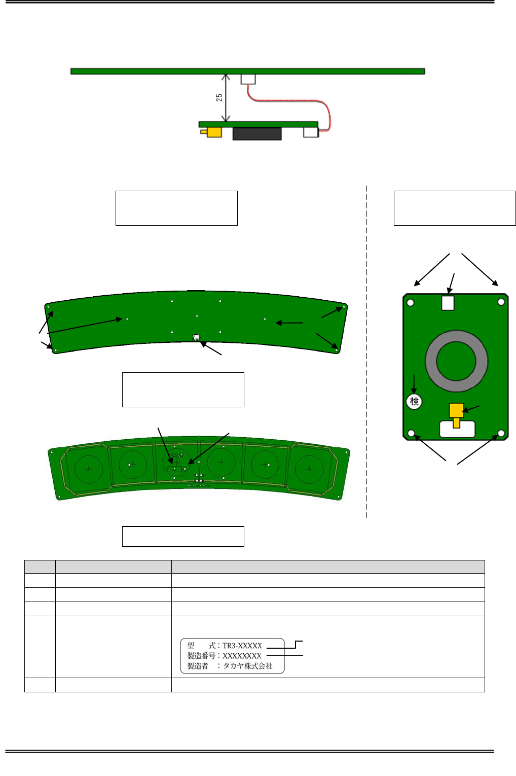
4.2.3 TR3-CA044
■ Specifications
Specifications
Item
Parameter
Applicable
Standards
RoHS
EU RoHS(2002/95/EC) Support
Antenna
Resonant
frequency
13.56MHz(Ta=25℃)
Antenna Type
LOOP ANTENNA
Connector
CN1
Connector : SMA(J)
Pin assignment
Symbol
Function
Center Contact
RF
RF input
Shell
GND
GND
Mechanical
data
Dimensions
(W x D x H)
TR3-CA044:433.2 (W)×91.1(D)×7.1(H)mm
09019P16:55 (W)×80(D)×15.6(H)mm
Weight
TR3-CA044:96g
09019P16:47g
Ambient
Conditions
Temperature
Operating range
0 to 40 degree
Humidity Operating
range
30 to 80%RH
Temperature
Storage range
0 to 55 degree
Humidity
Storage range
30 to 80%RH
Other
Accessories
Twisted pare cables
Model Name : TR3-AC-1A-090
①1.5D-2V SMA(P)-SMB(J) + Ferrite core
Model Name : WIR42763 + E04SR241336A(3 turn)
②1.5D-2V SMB(P)-SMB(P) + Ferrite core
Model Name : 09019M16 ( E04SR0200935A (3 turn))
①
②
Manual No.TDR-MNL-L4D01-24-EN-100
4 Specifications
4.2 Antenna
21
TAKAYA RFID TR3 Series
■ Dimensions
○TR3-CA044
11-Φ3.2
200
4-R5
433.23
91.11
(7.1)
5.5
○09019P16
Unit:mm
Tolerance:±1mm
Substrate thickness : 1.6mm
Unit:mm
Tolerance:±1mm
Substrate thickness : 1.6mm
Manual No.TDR-MNL-L4D01-24-EN-100
4 Specifications
4.2 Antenna
22
TAKAYA RFID TR3 Series
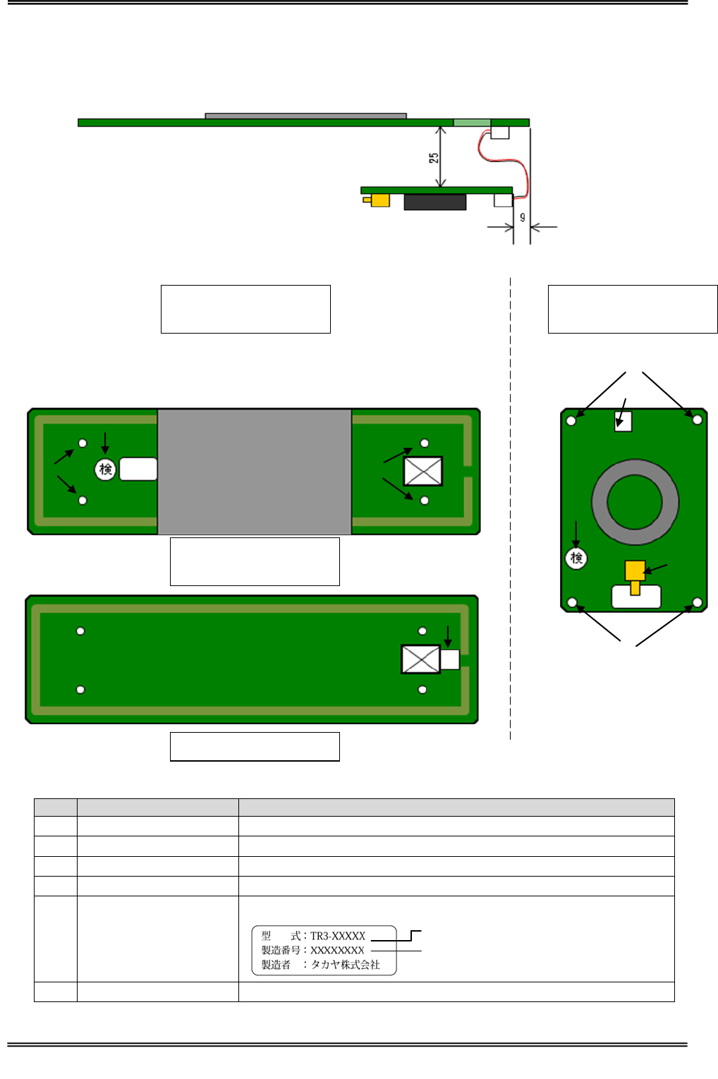
4.2.4 TR3-CA045
■ Specifications
Specifications
Item
Parameter
Applicable
Standards
RoHS
EU RoHS(2002/95/EC) Support
Antenna
Resonant
frequency
13.56MHz(Ta=25℃)
Antenna Type
LOOP ANTENNA
Connector
CN1
Connector : SMA(J)
Pin assignment
Symbol
Function
Center Contact
RF
RF input
Shell
GND
GND
Mechanical
data
Dimensions
(W x D x H)
TR3-CA045:424 (W)×84(D)×8.2(H)mm
09019P14:55 (W)×80(D)×15.6(H)mm
Weight
TR3-CA045:108g
09019P14:47g
Ambient
Conditions
Temperature
Operating range
0 to 40 degree
Humidity Operating
range
30 to 80%RH
Temperature
Storage range
0 to 55 degree
Humidity
Storage range
30 to 80%RH
Other
Accessories
Twisted pare cables
Model Name : TR3-AC-1A-090
①1.5D-2V SMA(P)-SMB(J) + Ferrite core
Model Name : WIR42763 + E04SR200935A(2 turn)
②1.5D-2V SMB(P)-SMB(P) + Ferrite core
Model Name : 09019M16 ( E04SR0200935A (3 turn))
①
②
Manual No.TDR-MNL-L4D01-24-EN-100
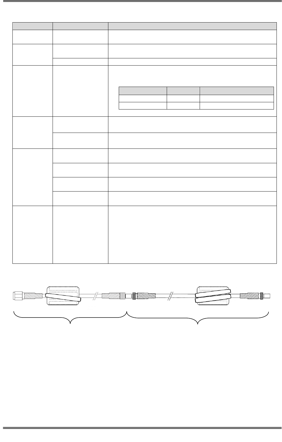
4 Specifications
4.2 Antenna
23
TAKAYA RFID TR3 Series
■ Dimensions
○TR3-CA045
6.6
(8.2)
424
4-R3
84
○09019P14
Unit:mm
Tolerance:±1mm
Substrate thickness : 1.6 mm
Unit:mm
Tolerance:±1mm
Substrate thickness : 1.6mm
Manual No.TDR-MNL-L4D01-24-EN-100
4 Specifications
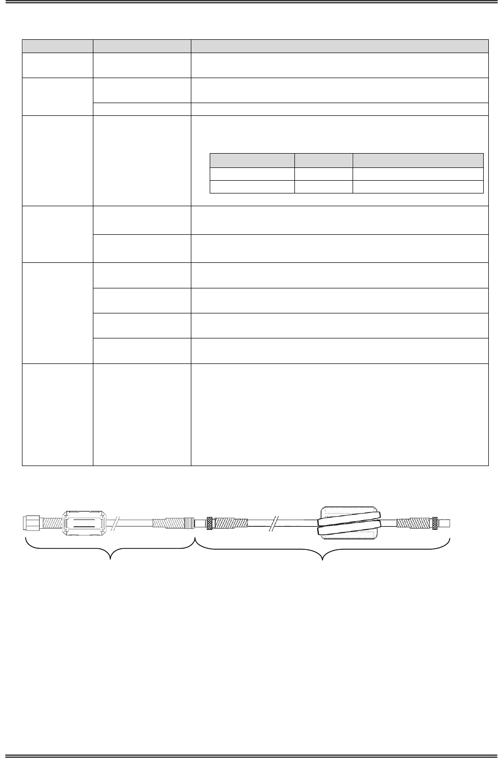
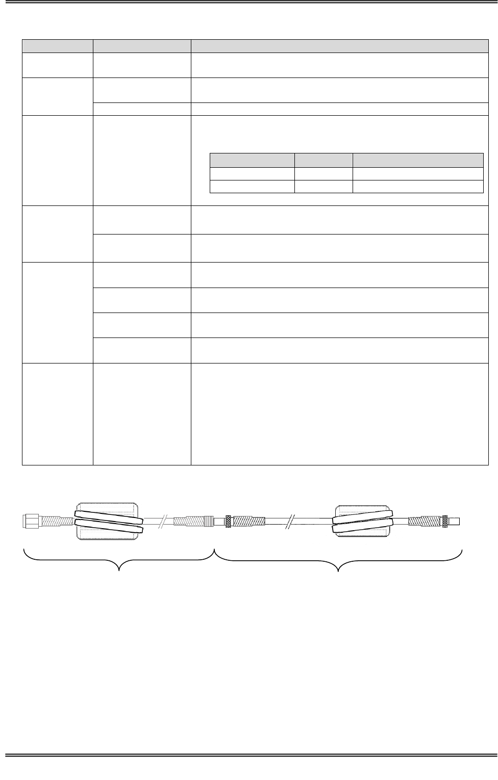
4.3 Coupler Cable
24
TAKAYA RFID TR3 Series
4.3 Coupler Cable
Coupler Cable (between Antenna to coupler board)
TR3-AC-1A-***
Enter the cable length
90mm : 090
120mm : 120
■ Specifications
item
Parameter
RoHS
EU RoHS(2002/95/EC) Support
Linetype
AWG26
Connector
PH-PH
Cable loss
90mm : approx. 0.061dB
120mm : approx. 0.081dB
■ Dimensions
(Cable Length)
( )is Recommended Dimension
Manual No.TDR-MNL-L4D01-24-EN-100
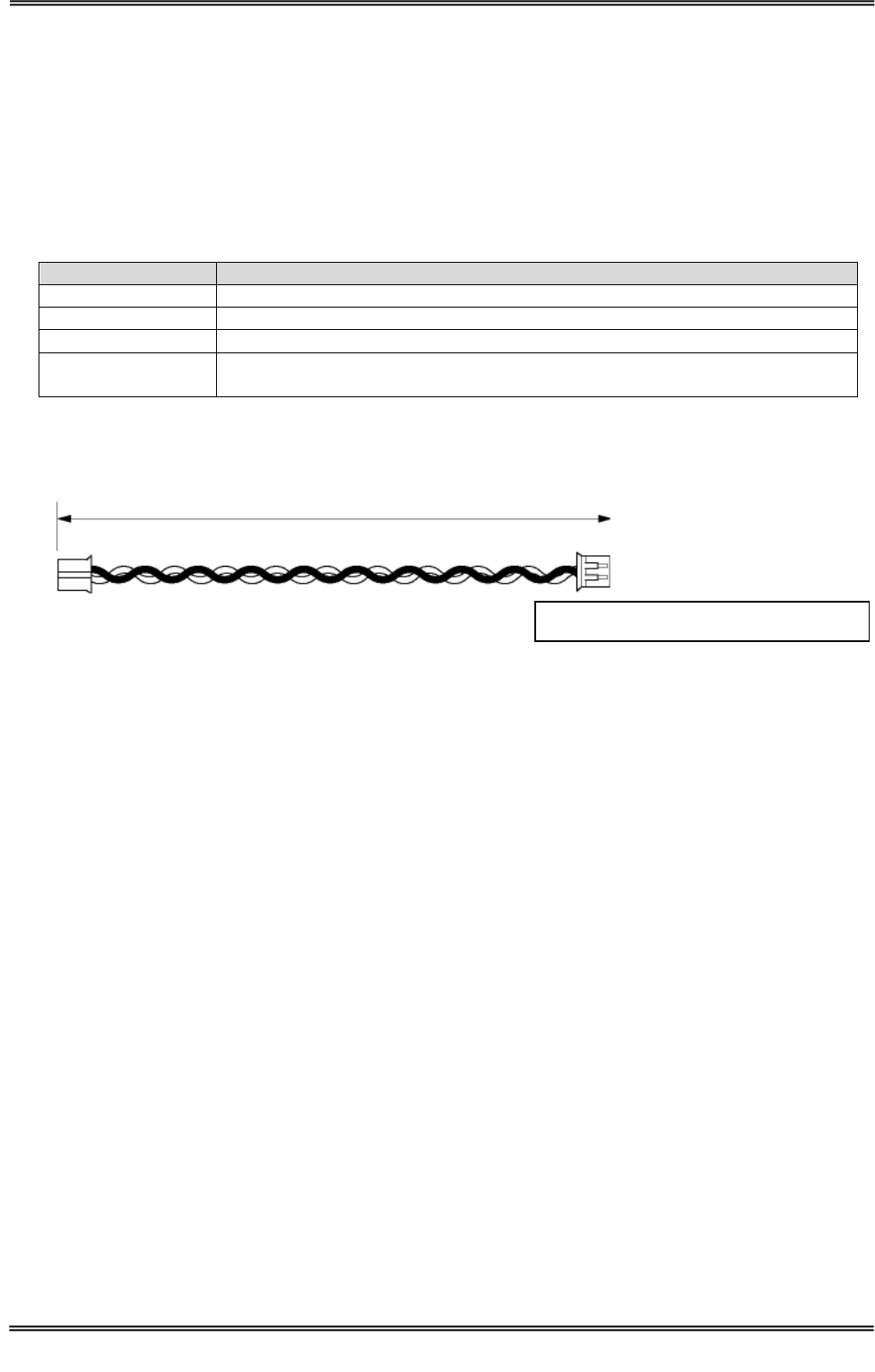
4 Specifications
4.4 Antenna Cable
25
TAKAYA RFID TR3 Series
4.4 Antenna Cable
4.4.1 WIR42696
■ Specifications
item
Parameter
RoHS
EU RoHS(2002/95/EC) Support
Linetype
Coaxial cable 1.5D-2V
Connector
SMA(P)-SMB(J)
Cable loss
approx. 0.043dB
■ Dimensions
4.4.2 WIR42763
■ Specifications
Item
Parameter
RoHS
EU RoHS(2002/95/EC) Support
Linetype
Coaxial cable 1.5D-2V
Connector
SMA(P)-SMB(J)
Cable loss
approx. 0.051dB
■ Dimensions
500
Unit:mm
600
Unit:mm
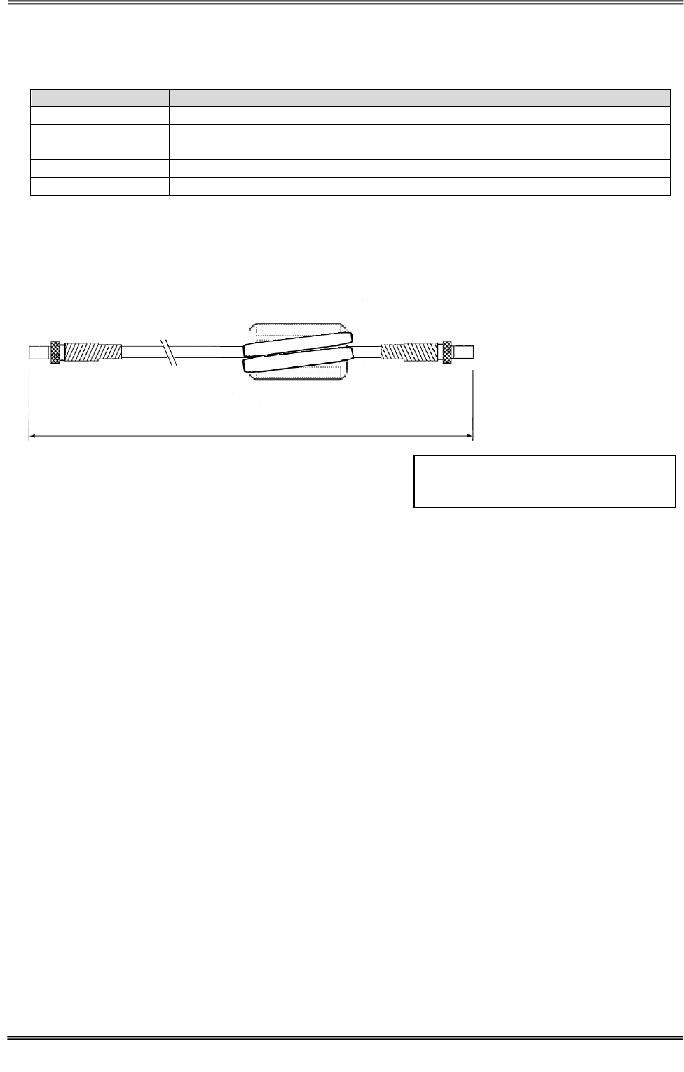
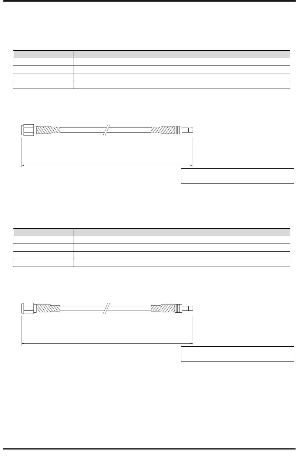
Manual No.TDR-MNL-L4D01-24-EN-100
4 Specifications
4.4 Antenna Cable
26
TAKAYA RFID TR3 Series
4.4.3 09019M16
■ Specifications
Item
Parameter
RoHS
EU RoHS(2002/95/EC) Support
Linetype
Coaxial cable 1.5D-2V
Connector
SMB(P)-SMB(P)
Cable loss
approx. 0.16dB
Ferrite core
E04SR0200935A(3 turn)
■ Dimensions
(1730)
Unit:mm
( )is Recommended Dimension
TR3-L4D01-24 Side
WIR42696 or
WIR42763 Side
Manual No.TDR-MNL-L4D01-24-EN-100
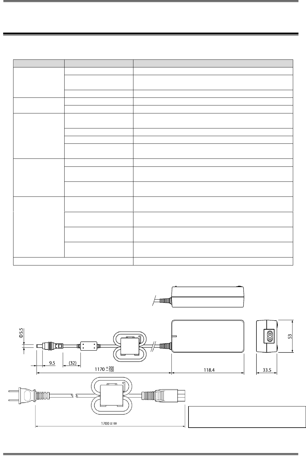
5 Accessories
5.1 AC Adapter(TR3-PWR-19V-2)
27
TAKAYA RFID TR3 Series
5 Accessories
5.1 AC Adapter(TR3-PWR-19V-2)
■ Specifications
Specifications
Item
Parameter
Applicable
Standards
EMI
FCC class B, CISPR 22 class B
COMPLY SAFETY
STANDARDS
UL60950, IEC60950, CSA22.2 No.60950,
LPS:Limited Power Source, PSE
RoHS
EU RoHS(2002/95/EC) Support
AC INPUT
VOLTAGE
AC100V to AC240V
FREQUENCY
50 to 60Hz
DC OUTPUT
DC OUTPUT
VOLTAGE RANGE
DC19.0V±5%
LOAD CURRENT
3.15A
OUTPUT
CENTER MINUS
PLUG TYPE
9.5×external diameterφ5.5
internal diameterφ2.1
Mechanical
data
Wight
approx. 500g
Dimensions
53(W) x 118.4(D) x 33.5(H)mm
(Cords are not included)
Cable length
DC Plug side:approx. 1170mm
AC Plug side:approx. 1700mm
Ambient
Conditions
Temperature
Operating range
0 to 40 degree
Humidity Operating
range
10 to 85%RH
Temperature
Storage range
-25 to 60 degree
Humidity
Storage range
10 to 95%RH
Ferrite core
MSFC 13K(4 turn) 2pcs
■ Dimension
Unit:mm
( )is Recommended Dimension
Ferrite Core
Manual No.TDR-MNL-L4D01-24-EN-100
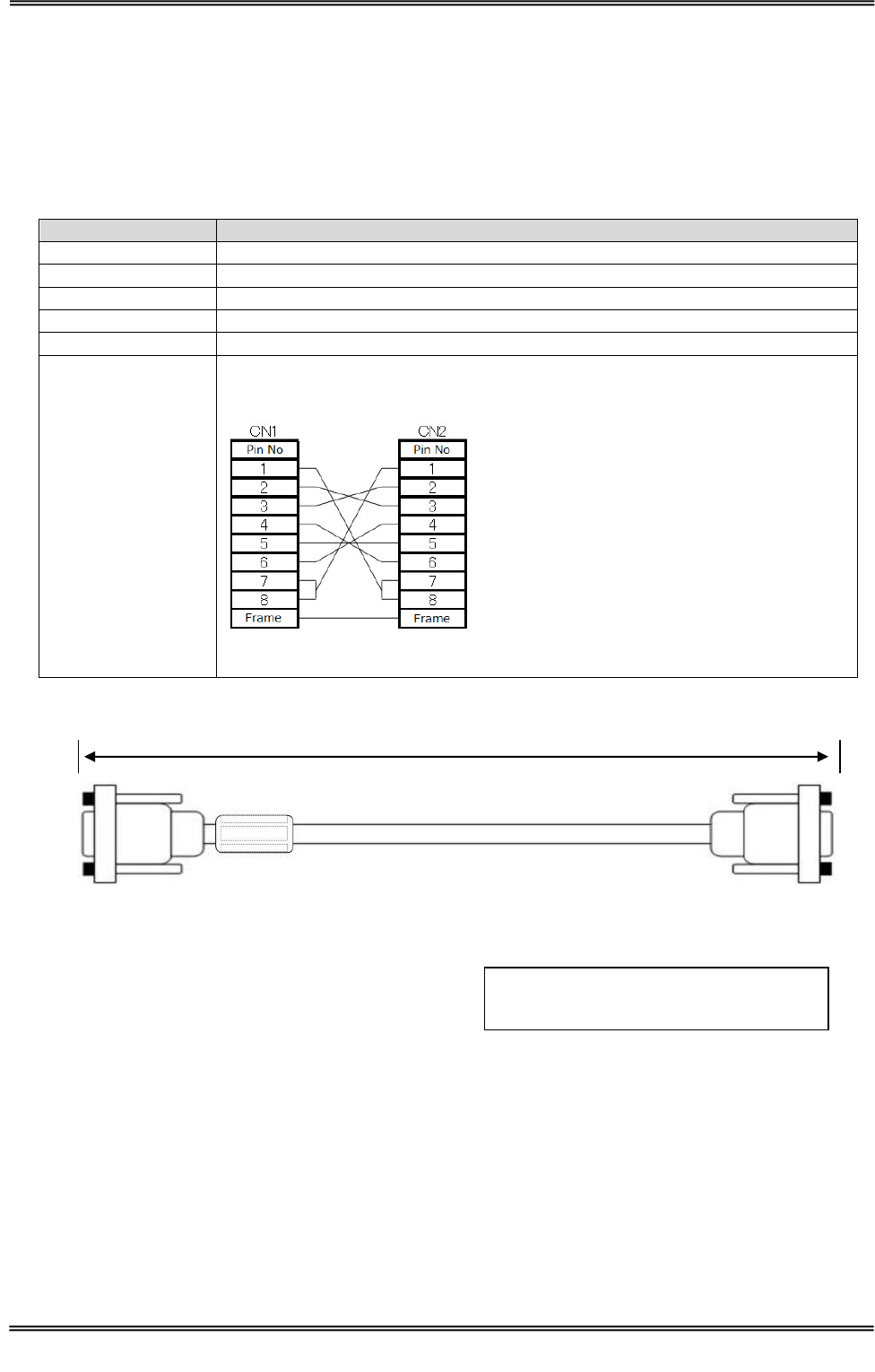
5 Accessories
5.2 RS232C Cross-cable(CB-232C-3)
28
TAKAYA RFID TR3 Series
5.2 RS232C Cross-cable(CB-232C-3)
Type of ferrite core and number of turns are specified by compliance for FCC.
Don’t change and remove the ferrite core.
Don’t uses except the bundled RS232C Cross-cable.
■ Specifications
Specifications
Parameter
RoHS
EU RoHS(2002/95/EC) Support
Connector
D-sub 9Pin
screw
Inch screw
Cable length
approx. 4.5m
Ferrite core
ZCAT17300730A(1 turn)
Connection
Cross-cable
■ Dimension
(4500)
Unit:mm
( )is Recommended Dimension
Host Device ( ex.PC ) Side
TR3-L4D01-24 Side
Manual No.TDR-MNL-L4D01-24-EN-100
29
TAKAYA RFID TR3 Series
6 Maintenance
This product is mainly used in electronic components and semiconductors.
Therefore, the long-term stable operation, the environment and conditions are expected to defect, as
shown below.
• Device degradation due to overvoltage and overcurrent.
• Device degradation due to high temperature and long-term stress.
• Poor contact of the connector and cause deterioration of insulation by moisture
or dust.
• Connector corrosion by corrosive gases.
In order to use this product at its best, please conduct routine or periodic inspections.
Item
Maintenance
Criteria
Ambient
conditions
Temperature
Temperature Operating range
0 to 40 degree
Humidity
Humidity Operating range
30 to 80%RH
Enclosure
rating
Check the dusty
None
Corrosive
Check the corrosion
None
Power
Input
Check the voltage
Input Voltage : DC19V±10%
Voltage
fluctuation
Check the Voltage fluctuation
Attachment
Product
Check the Screw
Checking and verifying
Check the Connector
Cable
Check the Cable break
None
Performance
Check the Performance
Work

Manual No.TDR-MNL-L4D01-24-EN-100
30
TAKAYA RFID TR3 Series
Revision History
Revision code
Date
Revised contents
1.00
2015/05/08
Original production