TDK SESUB BU 14808 Bluetooth SMART Transceiver User Manual TDK SESUB General Introduction Standard Ver
TDK Corporation SESUB BU Bluetooth SMART Transceiver TDK SESUB General Introduction Standard Ver
UserManual.wiki
>
TDK SESUB BU
>
14808 User Manual
Users Manual
Navigation menu
Upload a User Manual
Namespaces
Wiki Guide
HTML
PDF
Info
Views
User Manual
Discussion / Help
Navigation

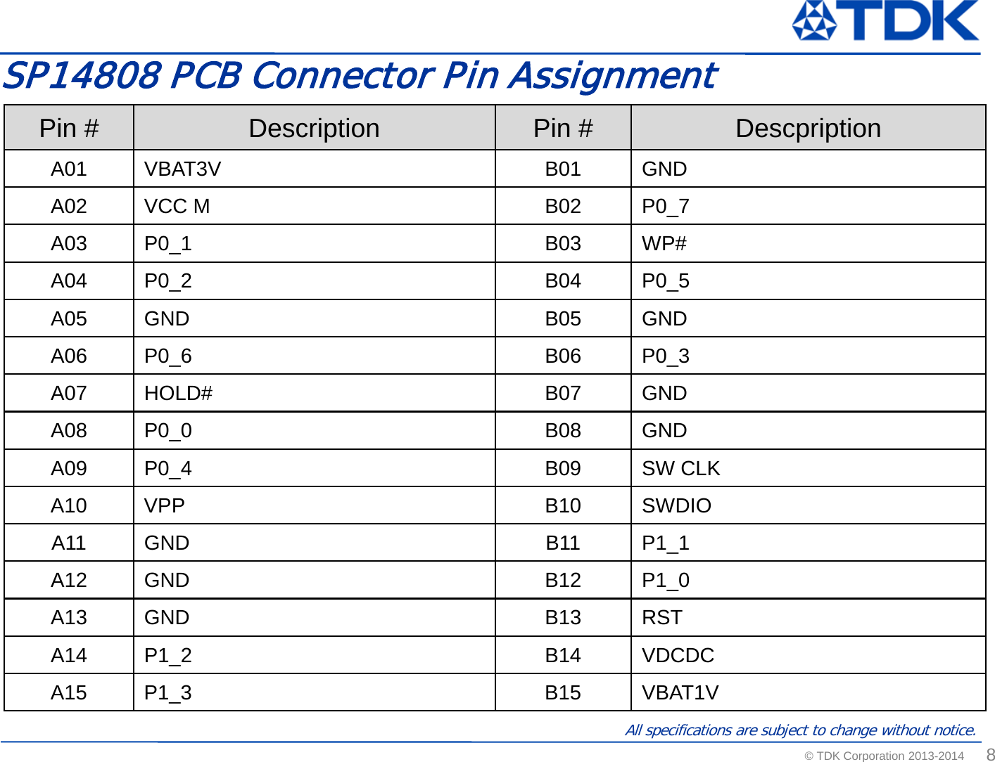
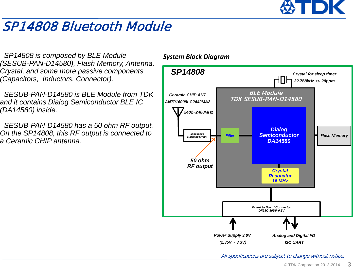
![© TDK Corporation 2013-2014 2 All specifications are subject to change without notice. SP14808 is a Bluetooth Smart compliant Module which is composed by world smallest size of TDK module SESUB-PAN-D14580 and Chip Antenna. SP14808 equips a 2.4GHz band chip antenna, a 32.768kHz sleep clock resonator. It is covered with a metal shield case on top. SP14808 Bluetooth Module SP14808 Connector DF23C-30DS-0.5V(92) [Hirose] 12.0 14.0 Covered with a metal shield case Ready for radio certification SP14808 006-x xxxxx xxxxxxx R Metal shield case Top View Bottom View Inside View (Under Metal shield case) SESUB-PAN-D14580](https://usermanual.wiki/TDK-SESUB-BU/14808/User-Guide-2526388-Page-2.png)

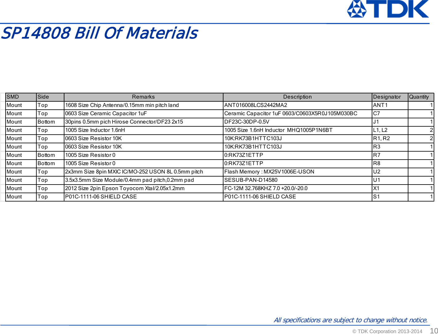
![© TDK Corporation 2013-2014 7 All specifications are subject to change without notice. General Performance Measured on SP14801 EM board with the condition of Ta=25℃+/-10℃ and VDD = 3.0V, fc=2440MHz Item Condition Value Unit Min Typ Max Tx Output power Maximum output power setting 0 - dBm Tx Frequency accuracy Maximum output power setting -150 0 +150 kHz Tx modulation characteristics Delta F1 225 275 kHz Receiver sensitivity level [measured by Packet Error Rate] Packet error rate : ≦30.8% -70 dBm RF Characteristics](https://usermanual.wiki/TDK-SESUB-BU/14808/User-Guide-2526388-Page-7.png)