TDK SESUB BU 14808 Bluetooth SMART Transceiver User Manual TDK SESUB General Introduction Standard Ver
TDK Corporation SESUB BU Bluetooth SMART Transceiver TDK SESUB General Introduction Standard Ver
Users Manual
© TDK Corporation 2013-2014
1
All specifications are subject to change without notice.
TDK Corporation
Thin Film Device Center
SESUB BU
Revision FC
2015.1.1
SP14808 Bluetooth Module User’s Guide
An Integrated 2.4GHz Bluetooth SMART Compliant Transceiver Module
© TDK Corporation 2013-2014
2
All specifications are subject to change without notice.
SP14808 is a Bluetooth Smart compliant Module which is composed by world smallest size of
TDK module SESUB-PAN-D14580 and Chip Antenna.
SP14808 equips a 2.4GHz band chip antenna, a 32.768kHz sleep clock resonator.
It is covered with a metal shield case on top.
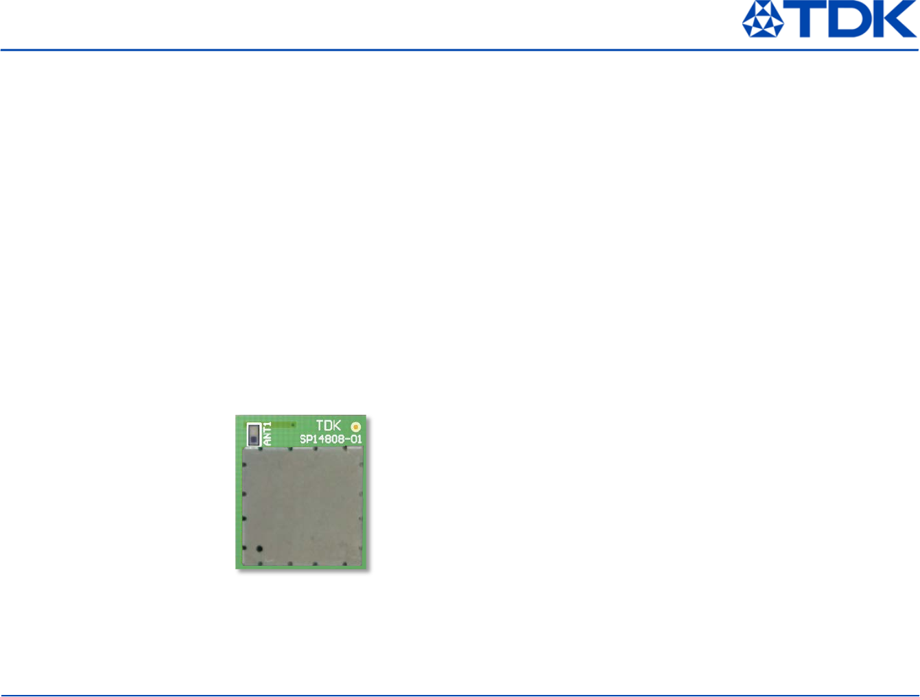
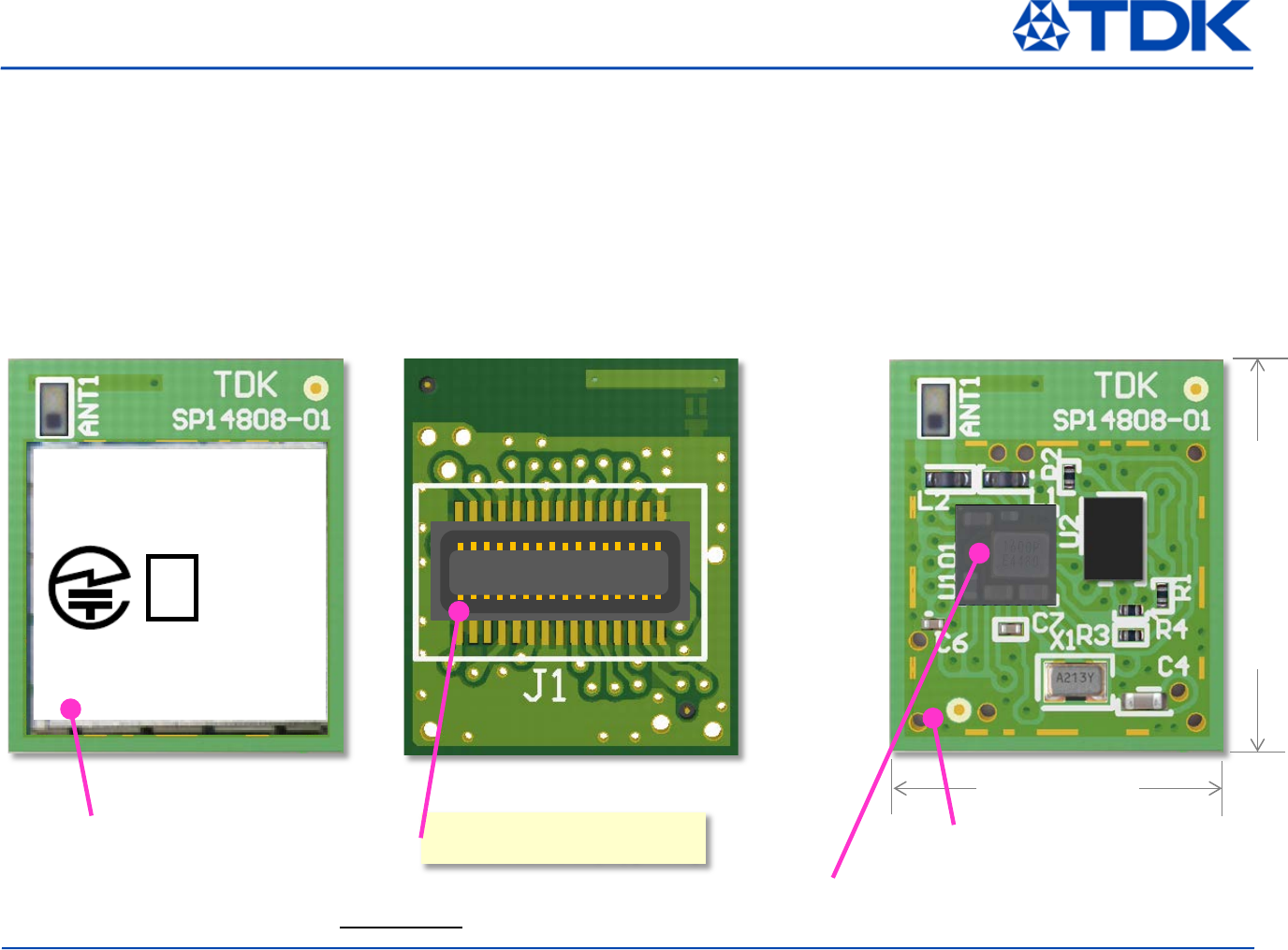
SP14808 Bluetooth Module
SP14808
Connector
DF23C-30DS-0.5V(92) [Hirose]
12.0
14.0
Covered with a metal shield case
Ready for radio certification
SP14808
006-x
xxxxx
xxxxxxx
R
Metal shield case
Top View Bottom View Inside View
(Under Metal shield case)
SESUB-PAN-D14580
© TDK Corporation 2013-2014
3
All specifications are subject to change without notice.
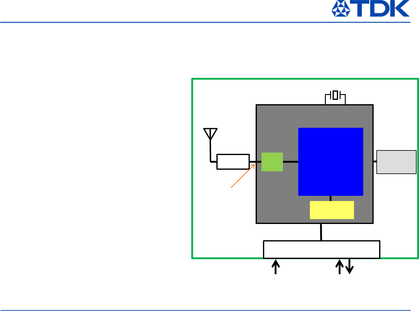
BLE Module
TDK SESUB-PAN-D14580
Ceramic CHIP ANT
ANT016008LC2442MA2
Board to Board Connector
DF23C-30DP-0.5V
SP14808
2402~2480MHz
Power Supply 3.0V
(2.35V ~ 3.3V)
Crystal for sleep timer
32.768kHz +/- 20ppm
Analog and Digital I/O
I2C UART
Filter
Impedance
Matching Circuit
Dialog
Semiconductor
DA14580
Crystal
Resonator
16 MHz
Flash Memory
System Block Diagram
SP14808 is composed by BLE Module
(SESUB-PAN-D14580), Flash Memory, Antenna,
Crystal, and some more passive components
(Capacitors, Inductors, Connector).
SESUB-PAN-D14580 is BLE Module from TDK
and it contains Dialog Semiconductor BLE IC
(DA14580) inside.
SESUB-PAN-D14580 has a 50 ohm RF output.
On the SP14808, this RF output is connected to
a Ceramic CHIP antenna.
50 ohm
RF output
SP14808 Bluetooth Module
© TDK Corporation 2013-2014
4
All specifications are subject to change without notice.
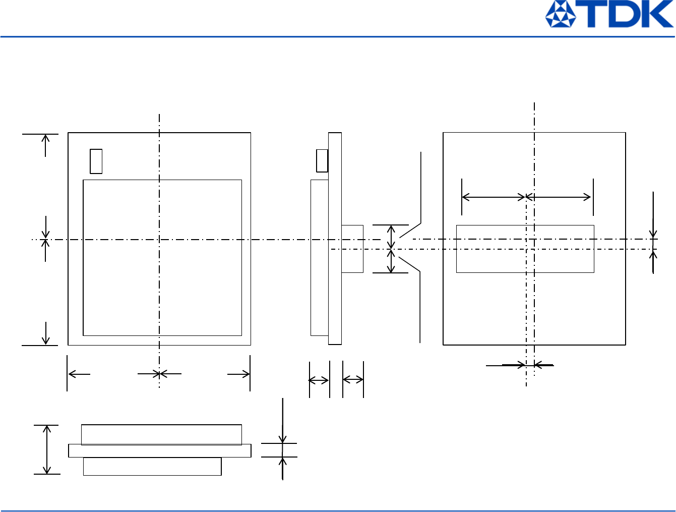
6.0
7.0
1.0±0.2
0.8
1.2
1.25
1.05
4.5
Unit in mm
Tolerance ±0.15mm unless otherwise noted.
3.1±0.2
CL
CL
4.5
CL
7.0
CL
6.0
1.05
0.8±0.1
SP14808 Mechanical Dimensions
© TDK Corporation 2013-2014
5
All specifications are subject to change without notice.
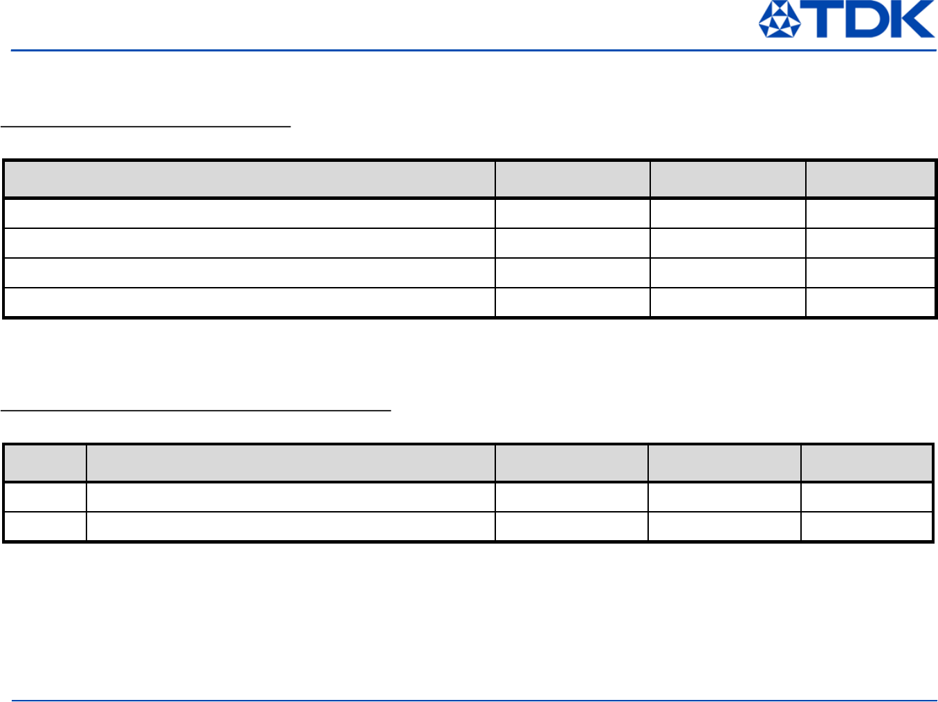
General Requirement under Operation
Over operating free-air temperature range (unless otherwise noted)
Item Min Max Unit
Supply voltage range -0.1 3.6 V
Storage temperature range -40 +85 ℃
ESD (charged Device Model) - 500 V
ESD (Human Body Model) - 1000 V
Absolute Maximum Ratings
Over operating free-air temperature range (unless otherwise noted)
Nr Item Min Max Unit
1 Operating supply voltage range 2.35 3.3 V
2 Operating ambient temperature range, Ta -20 +70 ℃
Recommended Operating Conditions
© TDK Corporation 2013-2014
6
All specifications are subject to change without notice.
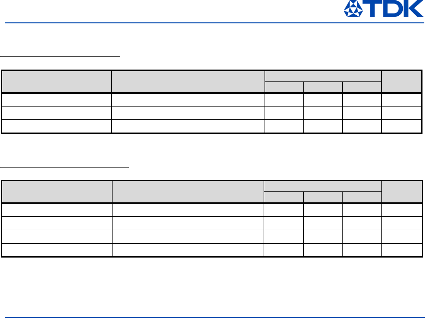
General Performance
Measured on SP14801 EM board with the condition of Ta=25℃+/-10℃ and VBAT = 3.0V
Item Condition Value Unit
Min Typ Max
Operational frequency range 2402 2480 MHz
Channel spacing 2 MHz
Number of RF Channels 40 Ch
RF Port impedance 50 Ohm
General RF Characteristics
Measured on SP14801 EM board with the condition of Ta=25℃+/-10℃ and VBAT = 3.0V
Item Condition Value Unit
Min Typ Max
Rx mode Current DCDC converter assumed ideal 5.0 mA
Tx mode Current DCDC converter assumed ideal 5.0 mA
Deep sleep current 8kB retention RAM active 0.9 μA
Electrical Characteristics
© TDK Corporation 2013-2014
7
All specifications are subject to change without notice.
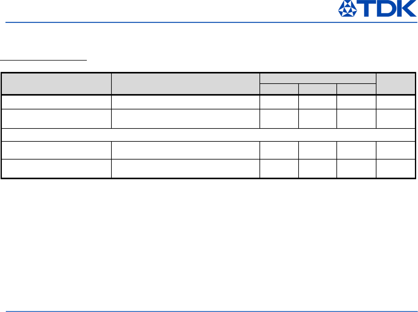
General Performance
Measured on SP14801 EM board with the condition of Ta=25℃+/-10℃ and VDD = 3.0V, fc=2440MHz
Item Condition Value Unit
Min Typ Max
Tx Output power Maximum output power setting 0 - dBm
Tx Frequency accuracy Maximum output power setting -150 0 +150 kHz
Tx modulation characteristics
Delta F1 225 275 kHz
Receiver sensitivity level
[measured by Packet Error Rate] Packet error rate : ≦30.8% -70 dBm
RF Characteristics
© TDK Corporation 2013-2014
8
All specifications are subject to change without notice.
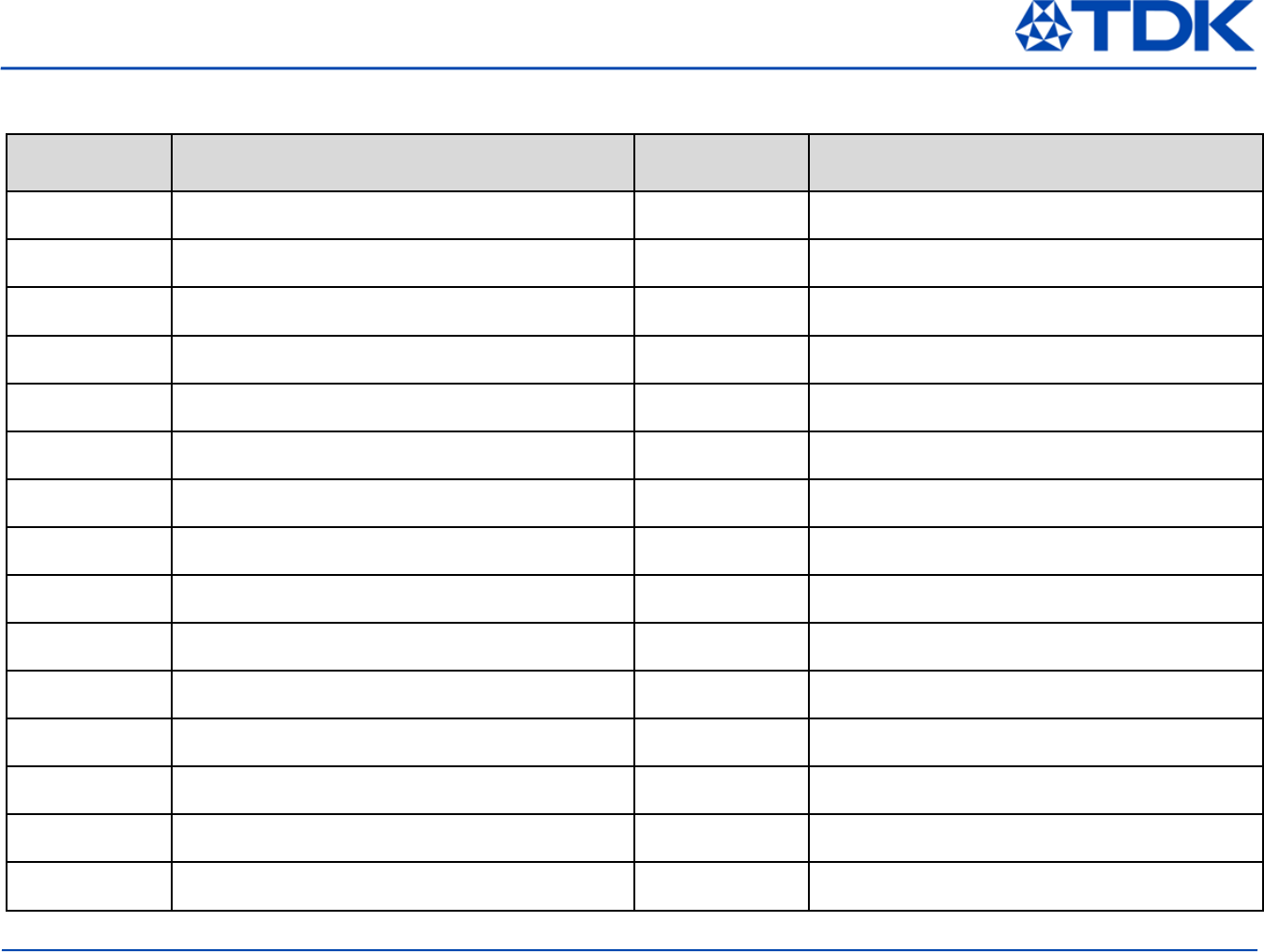
SP14808 PCB Connector Pin Assignment
Pin # Description Pin # Descpription
A01 VBAT3V B01 GND
A02 VCC M B02 P0_7
A03 P0_1 B03 WP#
A04 P0_2 B04 P0_5
A05 GND B05 GND
A06 P0_6 B06 P0_3
A07 HOLD# B07 GND
A08 P0_0 B08 GND
A09 P0_4 B09 SW CLK
A10 VPP B10 SWDIO
A11 GND B11 P1_1
A12 GND B12 P1_0
A13 GND B13 RST
A14 P1_2 B14 VDCDC
A15 P1_3 B15 VBAT1V
© TDK Corporation 2013-2014
9
All specifications are subject to change without notice.
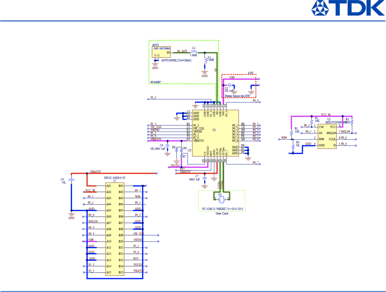
SP14808 SESUB-PAN-D14580 EM Schematic
© TDK Corporation 2013-2014
10
All specifications are subject to change without notice.
SP14808 Bill Of Materials
SMD Side Remarks Description Designator Qua ntity
Mount Top 1608 Size Chip Antenna/0.15mm min pitch land ANT016008LCS2442MA2 ANT1 1
Mount Top 0603 Size Ceramic Capacitor 1uF Ceramic Capacitor 1uF 0603/C0603X5R0J105M030BC C7 1
Mount Bo ttom 30pins 0.5mm pich Hirose Connector/DF23 2x15 DF23C-30DP-0.5V J1 1
Mount Top 1005 Size Inductor 1.6nH 1005 Size 1.6nH Inductor MHQ1005P1N6BT L1, L2 2
Mount Top 0603 Size Resistor 10K 10K:RK73B1HTTC103J R1, R2 2
Mount Top 0603 Size Resistor 10K 10K:RK73B1HTTC103J R3 1
Mount Bo ttom 1005 Size Resistor 0 0:RK73Z1ETTP R7 1
Mount Bo ttom 1005 Size Resistor 0 0:RK73Z1ETTP R8 1
Mount Top 2x3mm Size 8pin MXIC IC/MO-252 USON 8L 0.5mm pitch Flash Memory : MX25V1006E-USON U2 1
Mount Top 3.5x3.5mm Size Module/0.4mm pad pitch,0.2mm pad SESUB-PAN-D14580 U1 1
Mount Top 2012 Size 2pin Epson Toyocom Xtal/2.05x1.2mm FC-12M 32.768KHZ 7.0 +20.0/-20.0 X1 1
Mount Top P01C-1111-06 SHIELD CASE P01C-1111-06 SHIELD CASE S1 1

© TDK Corporation 2013-2014
11
All specifications are subject to change without notice.
Reference Information
1. Bluetooth Core Technical Specification document, version 4.1
https://www.bluetooth.org/en-us/specification/adopted-specifications
https://www.bluetooth.org/DocMan/handlers/DownloadDoc.ashx?doc_id=282159
2. Dialog Semiconductor DA14580 Low Power Bluetooth Smart System-on-Chip Datasheet
3. Dialog Semiconductor DA14580 Software Development Guide (UM-B-003)
4. Dialog Semiconductor DA14580 Peripheral Drivers User manual (UM-B-004)
5. Dialog Semiconductor DA14580 Bluetooth Low Energy Software Development Kit (SDK)
6. Dialog Semiconductor DA14580 End product testing and programming guidelines (AN-B-020)
7. Dialog Semiconductor DA14580 supply current measurements (AN-B-015)
8. Keil Embedded Workbench for ARM Cortex-M series devices programming
http://www.keil.com
9. For all other related technical documents, visit Texas Instruments Low-Power RF web site.
http://support.dialog-semiconductor.com/

© TDK Corporation 2013-2014
12
All specifications are subject to change without notice.
Certain Instructions.
User shall operate SP14808 within TDK’s recommended specifications and environmental considerations per the user’s guide, accompanying
documentation, and any other applicable requirements. Exceeding the specified ratings (including but not limited to input and output voltage,
current, power, and environmental ranges) for SP14808 may cause property damage, personal injury or death.
If there are questions concerning these ratings, user should contact a TDK field representative prior to connecting interface electronics
including input power and intended loads.
Any loads applied outside of the specified output range may result in unintended and/or inaccurate operation and/or possible permanent
damage to the SP14808 and/or interface electronics.
Please consult the applicable user's guide prior to connecting any load to the SP14808 output. If there is uncertainty as to the load
specification, please contact a TDK field representative.
Agreement to Defend, Indemnify and Hold Harmless.
User agrees to defend, indemnify, and hold TDK, its directors, officers, employees, agents, representatives, affiliates, licensors and their
representatives harmless from and against any and all claims, damages, losses, expenses, costs and liabilities (collectively, "Claims") arising out
of, or in connection with, any handling and/or use of SP14808.
User’s indemnity shall apply whether Claims arise under law of tort or contract or any other legal theory, and even if SP14808 fail to perform as
described or expected.
Safety-Critical or Life-Critical Applications.
User agrees that SP14808 shall not be used as, or incorporated into, all or any part of safety critical applications (such as life support),
and a failure of a TDK product considered for purchase by user for use in user’s product would reasonably be expected to cause severe
personal injury or death such as devices which are classified as FDA Class III or similar classification.

© TDK Corporation 2013-2014
13
All specifications are subject to change without notice.
REGULATORY COMPLIANCE INFORMATION
Caution
This device complies with part 15 of the FCC Rules.
Operation is subject to the following two conditions:
(1) This device may not cause harmful interference, and
(2) this device must accept any interference received, including interference that may cause undesired operation.
Changes or modifications not expressly approved by the party responsible for compliance could void the user's authority to operate the
equipment.
FCC Radio-Frequency Exposure and Approval Conditions:
1. This equipment complies with FCC radiation exposure limits set forth for an uncontrolled environment. The antenna(s) used for this
transmitter must not be collocated or operating in conjunction with any other antenna or transmitter within a host device,
except in accordance with FCC multi-transmitter product procedures..
2. The regulatory label on the final system must include the statement: “Contains FCC ID:2ACNB14808” or using electronic labeling method as
documented in KDB784748.
3. The final system integrator must ensure there is no instruction provided in the user manual or customer documentation indicating how to
install or remove the transmitter module except such device has implemented two-ways authentication between module and the host
system.