THALES DIS AlS Deutschland MC55I-W Quadband GSM/GPRS Module User Manual hio
Gemalto M2M GmbH Quadband GSM/GPRS Module hio
UserManual.wiki
>
THALES DIS AlS Deutschland
>
MC55I W User Manual
08 user guide
Navigation menu
Upload a User Manual
Namespaces
Wiki Guide
HTML
PDF
Info
Views
User Manual
Discussion / Help
Navigation
![MC55i-W Hardware Interface Overview1 Introduction14MC55i-W_HIO_v01.301 Page 6 of 30 2011-3-8Confidential / Released1 IntroductionThis document1 describes the hardware of the MC55i-W module that connects to the cellulardevice application and the air interface. It helps you quickly retrieve interface specifications,electrical and mechanical details and information on the requirements to be considered for in-tegrating further components.1.1 Related documents[1] MC55i-W AT Command Set[2] MC55i-W Release NotesPrior to using the MC55i-W modules or upgrading to a new firmware release, please carefullyread the latest product information.For further information visit the Cinterion Wireless Modules Website:http://www.cinterion.com1. The document is effective only if listed in the appropriate Release Notes as part of the technicaldocumentation delivered with your Cinterion Wireless Modules product.](https://usermanual.wiki/THALES-DIS-AlS-Deutschland/MC55I-W/User-Guide-1427668-Page-6.png)
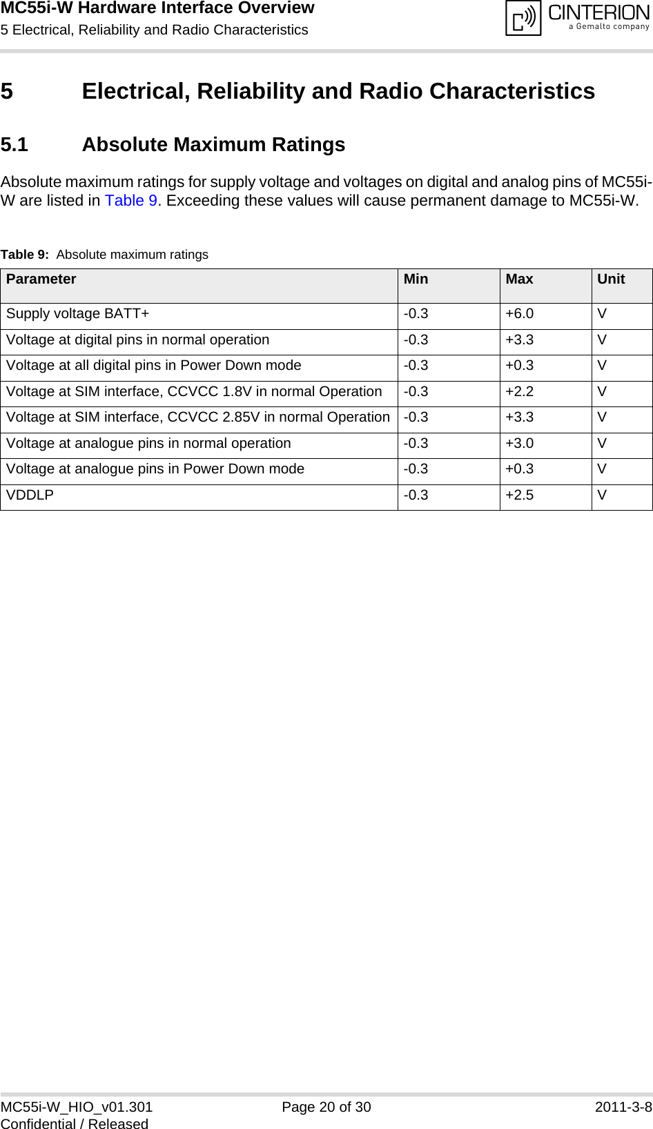
![MC55i-W Hardware Interface Overview5.2 Operating Temperatures25MC55i-W_HIO_v01.301 Page 21 of 30 2011-3-8Confidential / Released5.2 Operating TemperaturesPlease note that the module’s lifetime, i.e., the MTTF (mean time to failure) may be reduced, ifoperated outside the restriced temperature range. A special URC reports whether the moduleenters or leaves the restriced temperature range (see [1]; AT^SCTM).Note that within the specified operating temperature ranges the board temperature may varyto a great extent depending on operating mode, used frequency band, radio output power andcurrent supply voltage. When data are transmitted over GPRS the quad band module variant automatically reverts toa lower Multislot Class if the temperature rises to the limit specified for normal operation and,vice versa, returns to the higher Multislot Class if the temperature is back to normal. Table 10: Board temperatureParameter Min Typ Max UnitNormal operation -30 +25 +85 °CRestricted operation -40 to -30 +85 to +90 °CAutomatic shutdown1Temperature measured on MC55i-W board1. Due to temperature measurement uncertainty, a tolerance of ±3°C on the thresholds may occur.<-40 --- >+90 °CTable 11: Ambient temperature according to IEC 60068-2 (w/o forced air circulation)Parameter Min Typ Max UnitGSM Call @ max. RF-Power -40 +75 °CGPRS Class 8 @ max. RF-Power -40 +75 °CGPRS Class 10 @ max. RF-Power (quad band only) -40 +60 °CTable 12: Ambient temperature with forced air circulation (air speed 0.9m/s)Parameter Min Typ Max UnitGSM Call @ max. RF-Power -40 +80 °CGPRS Class 8 @ max. RF-Power -40 +80 °CGPRS Class 10 @ max. RF-Power (quad band only) -40 +70 °C](https://usermanual.wiki/THALES-DIS-AlS-Deutschland/MC55I-W/User-Guide-1427668-Page-21.png)