TRANE Package Units(both Units Combined) Manual L0905299
User Manual: TRANE TRANE Package Units(both units combined) Manual TRANE Package Units(both units combined) Owner's Manual, TRANE Package Units(both units combined) installation guides
Open the PDF directly: View PDF ![]() .
.
Page Count: 20

ITALLATIO
OPERATION
INT CE
WCX-IOM-1D
18-BB33D7-5
ALL phases of this installation must comply with
NATIONAL, STATE AND LOCAL CODES
Model:
WCX024G1
WCX030GI
WCX036G 1,3,4
WCX042G 1,3
WCX048G1,3,4
WCX060G1,3,4
Single Package Heat Pump
12 SEER Convertible
BAYLIFT002AA 2 " 5 TOn
LIFTING LUG KIT
IMPORTANT--This Document is customer propertyand is to remain with this unit. Please return to service information pack upon completion of work.
SAVINGTHEEARTH. SAVINGYOURMONEY.
All phases dthis installation must comply with the NATIONAL,
STATE & LOCAL CODES, In the absence of local codes, the
installation must conform with National Electric Code -- ANSI/
NFPA 70 or "LATEST REVISION."
Since The Trane Companyhas a policy of continuous product and product data
improvement, it reserves the right to change design and specification without notice.
NOTICE
Warnings and Cautions appear at appro-
priate locations throughout this manual.
Read these carefully.
_WARNING: Indicates a potentially haz-
ardous situation which, if not avoided, could
result in death or serious injury.
,_CAUTION" Indicates a potentially haz-
ardous situation which, if not avoided, may
result in minor or moderate injury. It may also
be used to alert against unsafe practices
and where property=damage=only accidents
could occur.
© 2002 American Standard Inc. All rights reserved o7/o2
GENERAL INFORMATION
IMPORTANT: Read this entire manual before beginning instal-
lation procedures.
SAFETY NOTICE• THIS INFORMATION IS INTENDED FOR
USE BY INDIVIDUALS POSSESSING ADEQUATE BACK-
GROUNDS OF ELECTRICAL AND MECHANICAL EXPERI-
ENCE. ANY ATTEMPT TO REPAIR A CENTRAL AIR CONDI-
TIONING PRODUCT MAY RESULT IN PERSONAL INJURY
AND/OR PROPERTY DAMAGE. THE MANUFACTURER OR
SELLER CANNOT BE RESPONSIBLE FOR THE INTERPRE-
TATION OF THIS INFORMATION, NOR CAN IT ASSUME
LIABILITY IN CONNECTION WITH ITS USE•
IMPORTANT: RECONNECT ALL GROUNDING DEVICES•
ALL PARTS OF THIS PRODUCT CAPABLE OF CONDUCTING
ELECTICAL CURRENT ARE GROUNDED. IF GROUNDING
WIRES, SCREWS, STRAPS, CLIPS NUTS OR WASHERS
USED TO COMPLETE A PATH TO GROUND ARE REMOVED
FOR SERVICE. THEY MUST BE RETURNED TO THIER ORIGI-
NAL POSITION AND PROPERLY FASTENED.
IMPORTANT: ALL POWER LEGS MAY NOT BE BROKEN BY
CONTACTORS. SEE WIRING DIAGRAM ON UNIT CONTROL
BOX COVER.
BEFORE STARTING THE COMPRESSOR, THE CRANKCASE
HEATER SHOULD BE ENERGIZED FOR EIGHT HOURS
Read this manual carefully before attempting to install, operate, or
perform maintenance on this unit. Installation and maintenance
should be performed by qualified service technicians only.
NOTE: "Warnings" and "Cautions" appear at appropriate
places in this manual Your personal safety and the proper
operation of this air conditioning product require that you follow
them carefully. The manufacturer assumes no liability for
installations or servicing performed by unqualified personnel.
INSPECTION
1. Check for damage after the unit is unloaded. Report promptly,
to the carrier, any damage found to the unit. Do not drop the unit.
IMPORTANT: The use of"spreader bars" is required when |
3
hoisting the unit ( to prevent damage to sides and top ). i
2. Check the unit's nameplate to determine if the unit is correct for
the intended application. The power supply must be adequate
for both the unit and all accessories.
3. Check to be sure the refrigerant charge has been retained during
shipment. Access to 1/4" flare pressure taps may be gained by
removing the furnace compartment access panel.
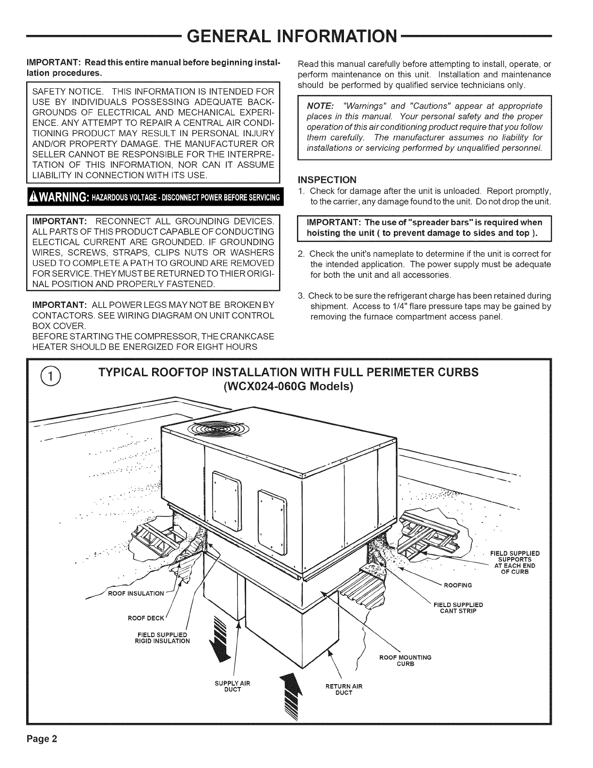
©TYPICAL ROOFTOP INSTALLATION WITH FULL PERIMETER CURBS
(WCX024=060G Models)
FIELD SUPPLIED
SUPPORTS
AT EACH END
OF CURB
ROOF
FIELD SUPPLIED
RIGIDINBULATION
SUPPLY AIR
DUCT RETURN AIR
DUCT
ROOF MOUNTING
CURB
FIELD SUPPLIED
CANT STRIP
Page 2
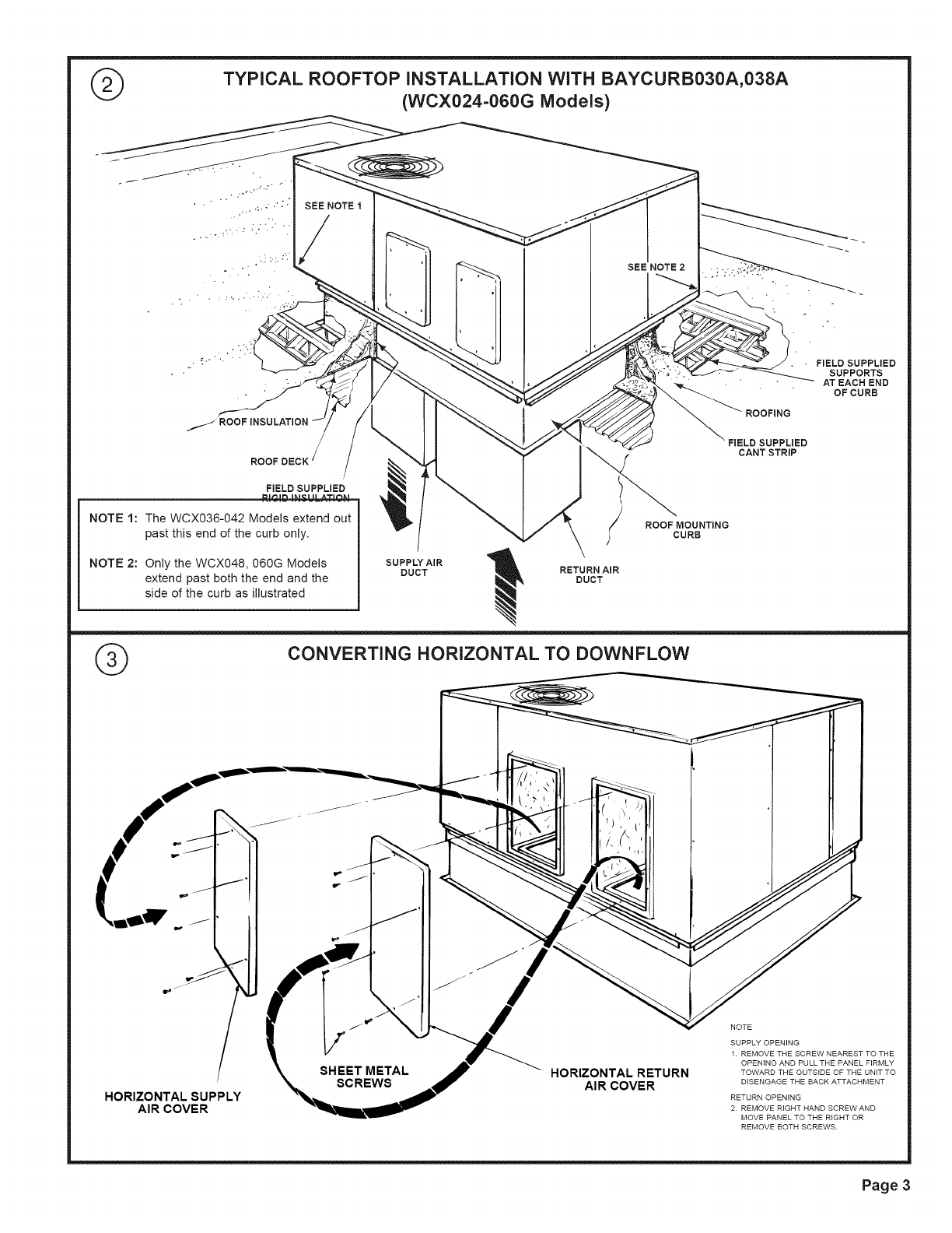
@TYPICAL ROOFTOP iNSTALLATiON WiTH BAYCURB030A,038A
(WCX024-060G IVlodels)
SEE NOTE 1
SEE NOTE2
._ROOFINSULATION
ROOF
FIELD SUPPLIED
NOTE 1: The WCX036-042 Models extend out
past this end of the curb only.
NOTE 2: Only the WCX048, 060G Models
extend past both the end and the
side of the curb as illustrated
SUPPLY AIR
DUCT
ROOF MOUNTING
)CURB
RETURN AiR
DUCT
®CONVERTING HORIZONTAL TO DOWNFLOW
ROOFING
FIELD SUPPLIED
CANTSTRIP
FIELD SUPPLIED
SUPPORTS
ATEACH END
OFCURB
o
HORIZONTAL SUPPLY
AIR COVER
SHEET METAL
SCREWS HORIZONTAL RETURN
AIR COVER
NOTE
SUPPLY OPENING
1. REMOVE THE SCREW NEAREST TO THE
OPENING AND PULL THE PANEL FIRMLY
TOWARD THE OUTSIDE OF THE UNIT TO
DISENGAGE THE BACK ATTACHMENT
RETURN OPENING
2. REMOVE RIGHT HAND SCREW AND
MOVE PANEL TO THE RIGHT OR
REMOVE BOTH SCREWS
Page 3
DiMENSiONAL DATA
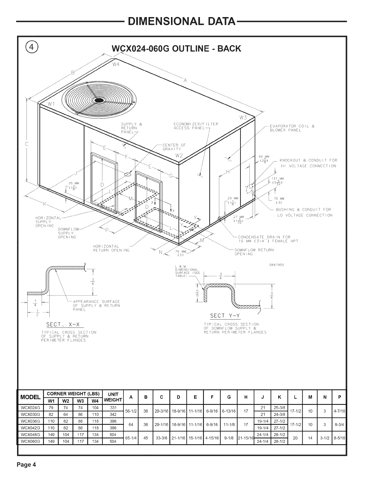
@ _ W_X024-060G OUTLINE =BACK
_r_ A
EVAPORA[OR CO I L &
_owER_ANE_
SUPPLY < <_- "_'_'-.'.,,,. /[! .52}
\\ ............................................................ I
1 __ .........APP/ ARANC_ _r_ r_ /I
YPICA[ (}ROSS S]CIION RETURN PER METER FLANGES
MODEL CORNER WEIGHT (LBS) UNIT A B C D E F G H J K L M N P
W1 W2 W3 W4 WEIGHT
WCX024G 79 74 74 104 331 21 25-3/8
56-1/2 36 29-3/16 18-9/16 11-1/16 6-9/16 6-13/16 17 17-1/2 10
WCX030G 82 64 86 110 342 21 24-3/8 3 4-7/16
WCX036G 110 82 88 118 398
WCX042G 110 82 88 118 398
19-1/4 27-1/2
64 36 29-1/16 18-9/16 11-1/16 6-9/16 11-1/8 17 17-1/2 10 3 8-3/4
19-1/4 27-1/2
WCX048G 149 104 117 134
WCX060G 149 104 117 134
504 24-1/4 28-1/2
65-1/4 45 33-3/8 21-1/16 15-1/16 4-15/16 9-1/8 21-15/1_ 20
504 24-1/4 28-1/2 14 3-1/2 8-5/16
Page 4
DiMENSiONAL DATA
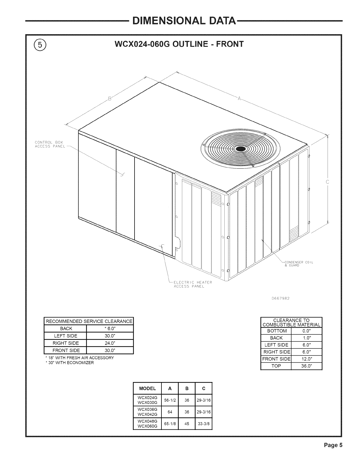
WCX024=060G OUTLINE = FRONT
CONTRO. BOX
ACC SS _AN£L
_C©NDENSER COIL
& GUARD
\ ELECTRIC HEAIER
ACCESS PANEL
D66Y982
RECOMMENDED SERVICE CLEARANCE
BACK * 6.0"
LEFT SIDE 30.0"
RIGHT SIDE 24.0"
FRONT SIDE 30.0"
18"WITH FRESHAIR ACCESSORY
30" WITH ECONOMIZER
CLEARANCE TO
COMBUSTIBLE MATERIAL
BOTTOM 0.0"
BACK 1.0"
LEFT SIDE 6.0"
RIGHT SIDE 6.0"
FRONT SIDE 12.0"
TOP 36.0"
MODEL A B C
WCX024G 56-1/2 36 29-3/16
WCX030G
WCX036G 64 36 29-3/16
WCX042G
WCX048G 65-1/8 45 33-3/8
WCX060G
Page 5
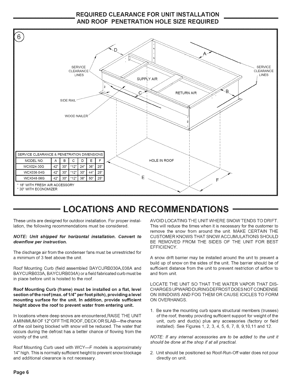
REQUIRED CLEARANCE FOR UNiT iNSTALLATiON
AND ROOF PENETRATION HOLE SiZE REQUIRED
SERVOE SERVOE
SIDE RAIL /'"//._
woo
I I I E
I E E
I E E
E
SERVICE CLEARANCE & PENETRATION DIMENSIONS __ _J_ Ii I
MODEL NO. A B C D E F HOLE IN ROOF
WCX024-30G 42" 30" "12" 24" 36" 25" _ I
WCX036-04G 42" 30" "12" 30" 44" 25" _ _i_
WCX048-06G 42" 30" "12" 36" 50" 25" E
* 18" WITH FRESH AIR ACCESSORY
* 30" WITH ECONOMIZER _
LOCATIONS AND RECOMMENDATIONS
These units are designed for outdoor installation. For proper instal-
lation, the following recommendations must be considered.
NOTE: Unit shipped for horizontal installation. Convert to
downflow per instruction.
The discharge air from the condenser fans must be unrestricted for
a minimum of 3 feet above the unit.
Roof Mounting Curb (field assembled BAYCURB030A,038A and
BAYCU RB033A, BAYCU RB034A) or a field fabricated curb must be
in place before unit is hoisted to the roof.
Roof Mounting Curb (frame) must be installed on a flat, level
section of the roof(max, of 1/4" per foot pitch), providing alevel
mounting surface for the unit. In addition, provide sufficient
height above the roof to prevent water from entering unit.
In locations where deep snows are encountered,RAiSE THE UNIT
A MINIMUM OF 12" OFF THE ROOF, DECK OR SLAB--the chance
of the coil being blocked with snow wilt be reduced. The water that
occurs during the defrost has a better chance of flowing from the
vicinity of the unit.
Roof Mounting Curb used with WCY--F models is approximately
14" high. This is normally sufficient height to prevent snow blockage
and additional clearance is not necessary.
AVOID LOCATING THE UNIT WHERE SNOW TENDS TO DRIFT.
This will reduce the times when it is necessary for the customer to
remove the snow from around the unit. MAKE CERTAIN THE
CUSTOMER KNOWS THAT SNOW ACCUMULATIONS SHOULD
BE REMOVED FROM THE SIDES OF THE UNIT FOR BEST
EFFICIENCY.
A snow drift barrier may be installed around the unit to prevent a
build up of snow on the sides of the unit. The barrier should be of
sufficient distance from the unit to prevent restriction of airflow to
and from unit.
LOCATE THE UNIT SO THAT THE WATER VAPOR THAT DIS-
CHARGES UPWARD DURING DEFROST DOES NOT CONDENSE
ON WINDOWS AND FOG THEM OR CAUSE ICICLES TO FORM
ON OVERHANGS.
1. Be sure the mounting curb spans structural members (trusses)
of the roof, thereby providing sufficient support for weight of the
unit, curb and duct(s) plus any accessories (factory or field
installed). See Figures 1, 2, 3, 4, 5, 6, 7, 8, 9,10,11 and 12.
NOTE. If any internal accessories are to be added to the unit it
should be done at the shop if at all practical.
2. Unit should be positioned so Roof-Run-Off water does not pour
directly on unit.
Page 6
3. For"RoofTop Application," unit must be elevated above roof with
a mounting Curb or Frame.
4. Exhaust vents or other sources of contaminated air should not be
near unit air inlet if outside air is to be introduced as a make-up
air or the economizer ventilation feature is to be used.
5. Check the handling facilities to insure the safety of personnel and
the unit(s).
6. CAUTION MUST BE TAKEN AT ALL TIMES TO AVOID PER-
SONAL INJURIES AND/OR DAMAGE TO EQUIPMENT.
7. The unit must be mounted level for proper drainage of defrost
water through the holes in the base pan.
8. Flexible duct connectors must be of a flame retardant material. All
duct work outside of the structure must be insulated and weath-
erproofed in accordance with local codes.
9. Roof flashing must be installed to seal the roof curb cavity and
must conform to local building codes.
10. Holes through exterior walls must be sealed in accordance with
local codes.
11. Access and service clearances for the unit must be given careful
consideration when locating the duct entrance openings. Fig-
ures 6 and 8 provide unit dimensions.
12. All fabricated outdoor ducts should be as short as possible.
13. Be sure the hole in the structure for the ducts is large enough to
accommodate the fabricated ducts and the insulation surrounding
them. (See Figure 6.)
CLEARANCES
1. The recommended clearances for single-unit installations are
illustrated in Figures 5 and 6. These minimum requirements are not
only an important consideration when determining unit placement,
but they are also essential to ensure adequate serviceability,
maximum capacity, and peak operating efficiency.
2. Any reduction of the unit clearances indicated in this illustration
may result in condenser coil starvation, or the recirculation of warm
condenser air. Actual clearances which appear to be inadequate
should be reviewed with a local sales engineer.
IMPORTANT!: To convert to downflow remove covers from
the downflow supply and return air openings and place them
over the horizontal supply and return air openings (painted
side out) and secure with sheet metal screws.
INSTALLATION
UNIT SUPPORT
If unit is to be roof mounted, check building codes for weight
distribution requirements. Refer to accessory roof curb mounting
instructions. Check unit nameplate for supply voltage required.
Determine if adequate electrical power is available. Refer to speci-
fication sheet.
LOCATION AND CLEARANCES
Installation of the unit should conform to local building codes or, in
the absence of local codes, to the ANSI/N FPA No. 70-1987 National
Electrical Code or "Latest Revision." Canadian installations must
conform to CSA and local codes.
IMPORTANT!: DO NOT LIFT THE UNIT WITHOUT TEST-
LIFTING FOR BALANCE AND RIGGING.DO NOT LIFT THE
UNIT IN WINDY CONDITIONS OR ABOVE PERSONNEL. DO
NOT LIFT THE UNIT BY ATTACHING A CLEVIS, HOOKS,
PINS OR BOLTS TO THE UNIT CASING, CASING HARD-
WARE, ANGLES, TABS OR FLANGES. FAILURE TO OB=
SERVE THESE WARNINGS MAY RESULT IN EQUIPMENT
DAMAGE.
4. When the curb and air ducts have been properly installed, the unit
is ready to be hoisted to the roof and set in position.
IMPORTANT!: "Spreader Bars" must be used when
hoisting unit.
5. IMPORTANT: The unit must be lowered into position P.V.C.
rubber tape on the curb flange permits the unit to be
repositioned if required without destroying the P.V.C. rub-
ber seals affixed to mounting curb.
Select a location that will permit unobstructed airflow into the
condenser coil and away from the fan discharge and permit unob-
structed service access into the compressor compartment. Sug-
gested airflow clearances and service clearances are given in
Figure 5.
PLACING AND RiGGiNG
1. Before preparing the unit for lifting, check the outline drawing for
center of gravity for lifting safety. Because of placement of
internal components, the unit weight may be unevenly distrib-
uted. Approximate unit weights are given in outline drawing on
page 3.
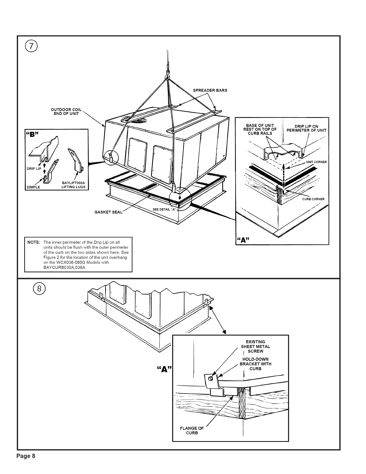
NOTE. Accessory BA YLIFTOO2M Four (A) lifting lugs are recom-
mended for rigging the unit for hoisting. See Figure 7 insert "B".
2. Insert the four lifting tugs in openings provided in drip lip on
perimeter of unit. See Figure 7 insert "B".
3. Before hoisting the unit, be sure that the proper method of rigging
is used, with straps or slings and spreader bars for protection
during lifting.
6. PLACING UNIT ON MOUNTING CURB--The unit is designed
with a perimeter drip lip that is lower than the unit base ban, see
Figure 7 insert "A".
7, Position the unit drip tip down over and in contact with the outside
corner of the curb, as illustrated in Figure 7 insert "A". Continue
to lower unit on top of curb, with the unit drip tip astraddle and in
contact with both the end and side rail of curb, the unit is now
resting on top of curb.
8. Take the two (2) hold down brackets shipped with curb and secure
unit to curb with hold down brackets as illustrated in Figure 8
insert "A".
Page 7
©
SPREADER BARS
OUTDOORCOIL
END OFUNIT
P_ BAYLIFT002A
DIMPLE LIFTING LUGS
GASKET SEAL'
NOTE: The inner perimeter of the Drip Lip on all
units should be flush with the outer perimeter
of the curb on the two sides shown here. See
Figure 2 for the location of the unit overhang
on the WCX036-060G Models with
BAYCU RB030A,038A.
BASE OF UNIT
REST ON TOP OF
CURB RAILS
DRIP LIP ON
PERIMETER OF UNIT
I
CURB CORNER
J
®
FLANGE OF
CURB
EXISTING
SHEET METAL
ISCREW
HOLD-DOWN
WITH
CURB
Page 8
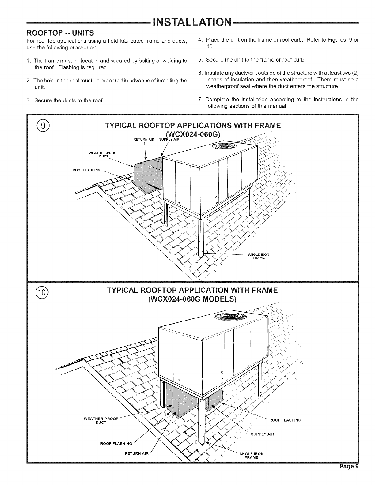
iNSTALLATiON
ROOFTOP ==UNITS
For roof top applications using a field fabricated frame and ducts, 4. Place the unit on the frame or roof curb. Refer to Figures 9 or
use the following procedure: 10.
1. The frame must be located and secured by bolting or welding to
the roof. Flashing is required.
2. The hole in the roof must be prepared in advance of installing the
unit.
5. Secure the unit to the frame or roof curb.
6. Insulate any ductwork outside of the structure with at least two (2)
inches of insulation and then weatherproof. There must be a
weatherproof seal where the duct enters the structure.
3. Secure the ducts to the roof. 7. Complete the installation according to the instructions in the
following sections of this manual.
®TYPICAL ROOFTOP APPLICATIONS WITH FRAME
lwcxo24-O6OG) , .
RETURN AIR SUP _ •
WEATHER-PROOF
DUCT
ROOF FLASHING
ANGLEIRON
FRAME
®TYPICAL ROOFTOP APPLICATION WITH FRAME
(WCX024=060G MODELS) /
DUCT
ROOF FLASHING
RETURN AIR
ROOF FLASHING
SUPPLY AIR
FRAME
Page 9
iNSTALLATiON
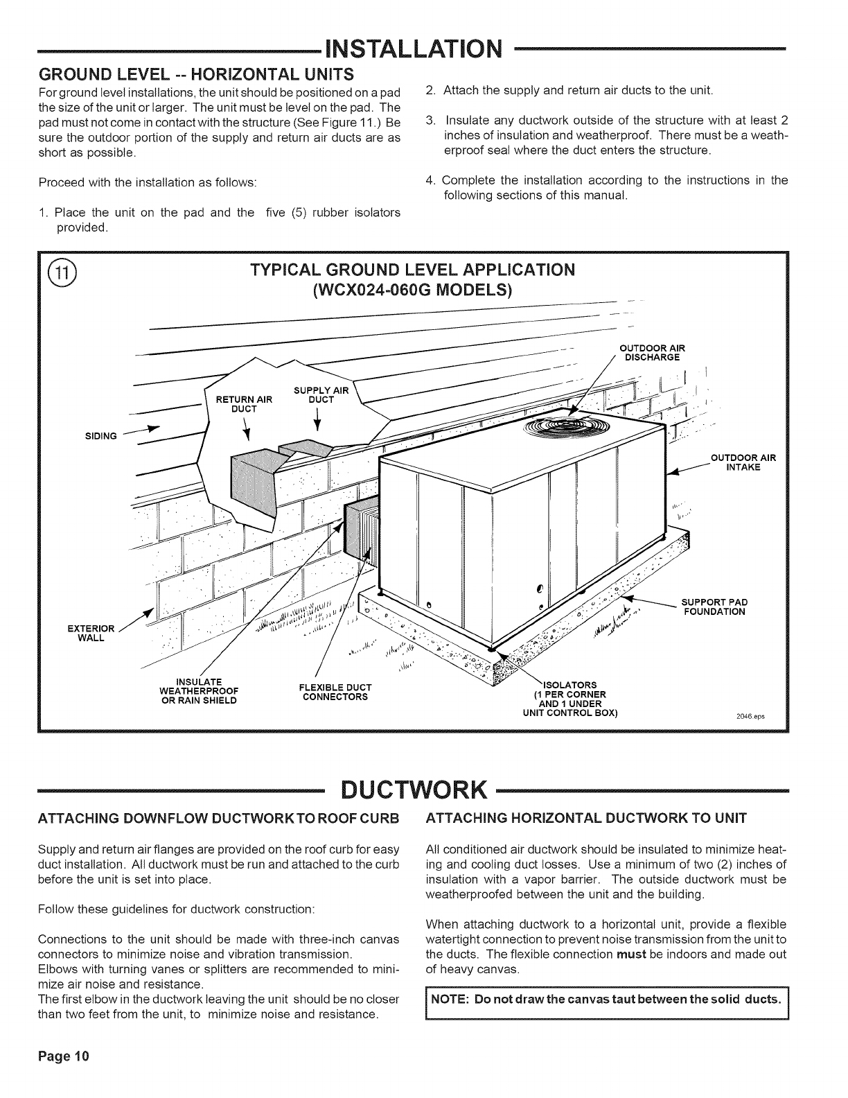
GROUND LEVEL ==HORIZONTAL UNITS
For ground level installations, the unit should be positioned on a pad
the size of the unit or larger• The unit must be level on the pad. The
pad must not come in contact with the structure (See Figure 11 .) Be
sure the outdoor portion of the supply and return air ducts are as
short as possible•
2. Attach the supply and return air ducts to the unit•
3. Insulate any ductwork outside of the structure with at least 2
inches of insulation and weatherproof• There must be a weath-
erproof seal where the duct enters the structure•
Proceed with the installation as follows:
1. Place the unit on the pad and the five (5) rubber isolators
provided•
4. Complete the installation according to the instructions in the
following sections of this manual•
®TYPICAL GROUND LEVEL APPLICATION
(WCX024-060G MODELS)
SUPPLY AIR
RETURN AIR DUCT
DUCT
SIDING I_P"
OUTDOOR AIR
DISCHARGE
I
'l
I '
EXTERIOR
WALL
OUTDOOR AIR
INTAKE
SUPPORT PAD
FOUNDATION
INSULATE
WEATHERPROOF FLEXIBLE DUCT ISOLATORS
OR RAIN SHIELD CONNECTORS (1 PER CORNER
AND 1 UNDER
UNIT CONTROL BOX) 2046eps
DUCTWORK
ATTACHING DOWNFLOW DUCTWORKTO ROOF CURB ATTACHING HORIZONTAL DUCTWORK TO UNiT
Supply and return air flanges are provided on the roof curb for easy
duct installation• All ductwork must be run and attached to the curb
before the unit is set into place•
Follow these guidelines for ductwork construction:
Connections to the unit should be made with three-inch canvas
connectors to minimize noise and vibration transmission•
Elbows with turning vanes or splitters are recommended to mini-
mize air noise and resistance•
The first elbow in the ductwork leaving the unit should be no closer
than two feet from the unit, to minimize noise and resistance•
All conditioned air ductwork should be insulated to minimize heat-
ing and cooling duct losses• Use a minimum of two (2) inches of
insulation with a vapor barrier• The outside ductwork must be
weatherproofed between the unit and the building•
When attaching ductwork to a horizontal unit, provide a flexible
watertight connection to prevent noise transmission from the unit to
the ducts• The flexible connection must be indoors and made out
of heavy canvas•
NOTE: Do not draw the canvas taut between the solid ducts. }
Page 10

®
FLANGE _FIELD DUCT
DUCT ATTACHMENT METHODS
AIR PROOF \
THIS SEAM
BASE
FIELD DUCT,ql X
U 'UNIT DUCT
FLANGE
/AIR PROOF
_THIS SEAM
FIELDDUCT4L _TBASE
Lt UNIT DUCT FLANGE
I
/AIR PROOF
UNITFLANGEDUCT_UNIT BASE
"FIELD DUCT
UNIT BASE
UNIT DUCT
FLANGE
WITH BUTYL OR
SILICONE
NOT RECOMMENDED FIELD DUCT
DOWNFLOW
/I_,. THIS SEAM
UNIT DUCT u _
FLANGE FIELD DUCT
HORIZONTAL
The following warning complies with State of California law, Proposition 65.
AWARNING: This product contains
fiberglass wool insulation! Fiberglass dust and ceramic
fibers are believed by the State of California to cause
cancer through inhalation. Glasswool fibers may also
cause respiratory, skin, or eye irritation.
CONDENSATE DRAIN PiPiNG
A 3/4-inch female NPT condensate drain connection is pro-
vided on the evaporator access panel end of the unit. See
Figure 4. Provide a trap and fill it with water before starting the
unit to avoid air from being drawn through. Follow local codes
and standard piping practices when running the drain line.
Pitch the line downward away from the unit, Avoid long
horizontal runs, See Figure 13.
NOTE: Do not use reducing fittings in the drain lines. The
condensate drain must be:
• Made of 3/4" pipe size.
• Pitched 1/4" per foot to provide free drainage to
convenient drain system,
• Trapped.
• Must not be connected to closed drain system.
TYPICAL CONDENSATE DRAIN PiPiNG
3/4" PVC OR COPPER
TUBING AND F
1-1/2" MIN.
Page 11
FILTER INSTALLATION
TABLE 1
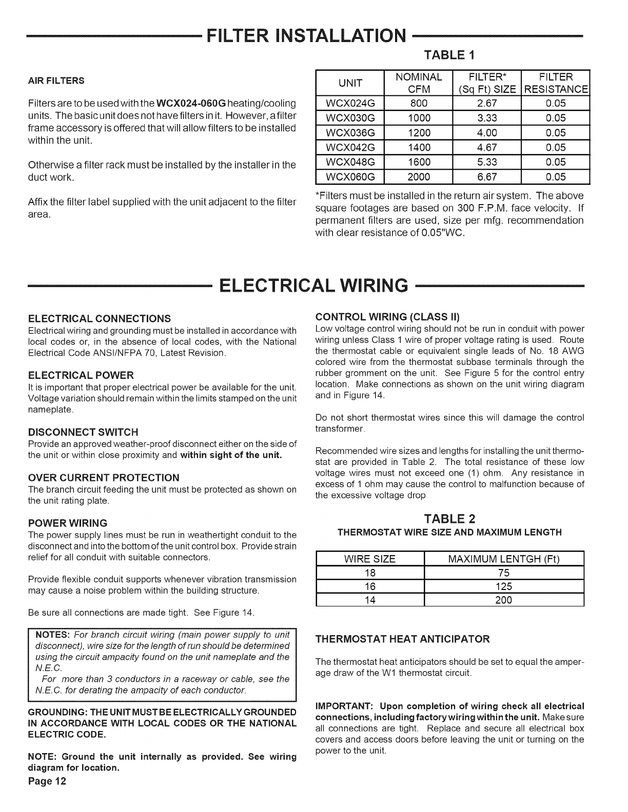
AiR FILTERS
Filters are to be used with the WCX024-060G heating/cooling
units. The basic unit does not have filters in it. However, afilter
frame accessory is offered that will allow filters to be installed
within the unit.
Otherwise a filter rack must be installed by the installer in the
duct work.
Affix the filter label supplied with the unit adjacent to the filter
area.
NOMINAL FILTER* FILTER
UNIT CFM (Sq Ft) SIZE RESISTANCE
WCX024G 800 2.67 0.05
WCX030G 1000 3.33 0.05
WCX036G 1200 4.00 0.05
WCX042G 1400 4.67 0.05
WCX048G 1600 5.33 0.05
WCX060G 2000 6.67 0.05
*Filters must be installed in the return air system. The above
square footages are based on 300 F.P.M. face velocity. If
permanent filters are used, size per mfg. recommendation
with clear resistance of 0.05"WC.
ELECTRICAL WIRING
ELECTRICAL CONNECTIONS
Electrical wiring and grounding must be installed in accordance with
local codes or, in the absence of local codes, with the National
Electrical Code ANSI/NFPA 70, Latest Revision.
ELECTRICAL POWER
It is important that proper electrical power be available for the unit.
Voltage variation should remain within the limits stamped on the unit
nameplate.
DISCONNECT SWITCH
Provide an approved weather-proof disconnect either on the side of
the unit or within close proximity and within sight of the unit.
OVER CURRENT PROTECTION
The branch circuit feeding the unit must be protected as shown on
the unit rating plate.
POWER WIRING
The power supply lines must be run in weathertight conduit to the
disconnect and into the bottom of the unit control box. Provide strain
relief for all conduit with suitable connectors.
Provide flexible conduit supports whenever vibration transmission
may cause a noise problem within the building structure.
Be sure all connections are made tight. See Figure 14.
NOTES: For branch circuit wiring (main power supply to unit
disconnect), wire size for the length of run should be determined
using the circuit ampacity found on the unit nameplate and the
N.E.C.
For more than 3 conductors in a raceway or cable, see the
N.E.C. for derating the ampacity of each conductor.
GROUNDING: THE UNiT MUST BE ELECTRICALLY GROUNDED
IN ACCORDANCE WITH LOCAL CODES OR THE NATIONAL
ELECTRIC CODE.
NOTE: Ground the unit internally as provided. See wiring
diagram for location.
Page 12
CONTROL WIRING (CLASS II)
Low voltage control wiring should not be run in conduit with power
wiring unless Class 1 wire of proper voltage rating is used. Route
the thermostat cable or equivalent single leads of No. 18 AWG
colored wire from the thermostat subbase terminals through the
rubber gromment on the unit. See Figure 5 for the control entry
location. Make connections as shown on the unit wiring diagram
and in Figure 14.
Do not short thermostat wires since this will damage the control
transformer.
Recommended wire sizes and lengths for installing the unit thermo-
stat are provided in Table 2. The total resistance dthese low
voltage wires must not exceed one (1) ohm. Any resistance in
excess of 1 ohm may cause the control to malfunction because of
the excessive voltage drop
TABLE 2
THERMOSTAT WIRE SIZE AND MAXIMUM LENGTH
WIRE SIZE MAXIMUM LENTGH (Ft)
18 75
16 125
14 200
THERMOSTAT HEAT ANTICIPATOR
The thermostat heat anticipators should be set to equal the amper-
age draw of the Wl thermostat circuit.
IMPORTANT: Upon completion of wiring check all electrical
connections, including factorywiringwithinthe unit. Make sure
all connections are tight. Replace and secure all electrical box
covers and access doors before leaving the unit or turning on the
power to the unit.
Afterallelectricalwiringiscomplete,setthethermostatsystem
switch in the OFF position so that the compressor will not run
and then apply power by closing the system main disconnect switch.
This will activate the compressor sump heat. Do not change the
Thermostat System Switch until power has been applied long
enough to evaporate any liquid R-22 in the compressor. It is
recommended that the sump heater be energized for eight (8) hours
prior to starting.
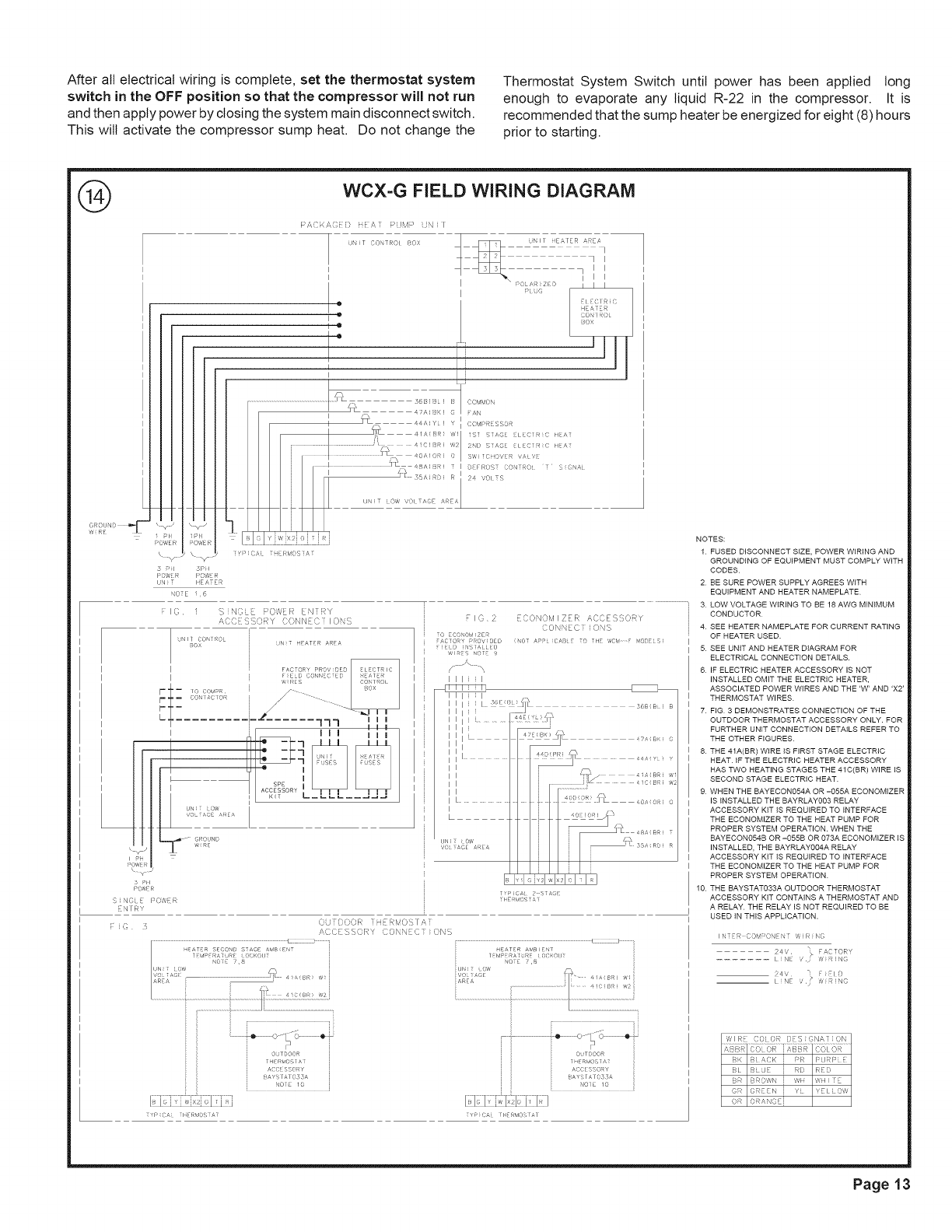
®WCX=G FIELD WIRING DIAGRAM
P/,,CKA( ) ii#' PUvIP N I
] T CO TRCI UQX
v -_
pl
_OwE nai,}E
< _i 5p I
c,4:R , _,,,,R
UN}T I EATER
CTE 1,6
I
I
I
" 1
o
Io
e
I
i
.........................................................................._L , 56B(BL) [
I
I' C(BR) 'A2
i{ ..........
j I /[ 35A( 0:, R
UN T O_ '/OI T/,GE #RE,",
i Y' ;/,[ [ Rb05? a;
':OM_,< '\
/,N
(}O'qF>FRi SSOR
1S] S /,©E [li(IR (1 II A
DEFROST ¢ONTRO_ T S_GN_i
24 VOt TS
i I
F
I
I
111............
vOL A©E AkEA
GIOUND
,?RE
y ,
5 Pii
PO'¢4R
NTRY
(" {
F IC I SINCLE PO,VEF_ ENiRY
AC C E S S C)R Y C C)N N E:C [ I 0 N S
-uNI_ CO_RCL
BOX UNiT HEATER AREA
....... 177
_2_ I
F I O 2 ECONOMI ZER ACCES C,SY
CONNEC ! ONS
_ _ (NOT APP CAB E TO TItE wc_/ F rODE S
[) NS]A I)
,,,<1 NO
liil
liil
II I
[44: .....
I I J I _' 'R £_'
I I................................................ ] • OA 01,:,
L ,_ ......
!,£ ,2_,,....... 4:!-...........
I I I,dxq{I,I I
TYP C# 2 S _GE
C,t DC}OR .... ,r,q _ ,
A,CCESSQRY 3ONN ,3T 'ONS
P c_ liER',O Ai
o JTDOOR
ACCE SSO_Y
BAY IA I O53A
NOIE 10
NOTES:
1 FUSED DISCONNECT SIZE, POWER WIRING AND
GROUNDING OF EQUIPMENT MUST COMPLY WITH
CODES
2 BE SURE POWER SUPPLY AGREES WITH
EQUIPMENT AND HEATER NAMEPLATE
3 LOW VOLTAGE WIRING TO BE 18 AWG MINIMUM
CONDUCTOR.
4 SEE HEATER NAMEPLATE FOR CURRENT RATING
OF HEATER USED.
5 SEE UNIT AND HEATER DIAGRAM FOR
ELECTRICAL CONNECTION DETAILS,
6 IF ELECTRIC HEATER ACCESSORY IS NOT
INSTALLED OMIT THE ELECTRIC HEATER,
ASSOCIATED POWER WIRES AND THE 'W' AND 'X2'
THERMOSTAT WIRES
7 FIG 3 DEMONSTRATES CONNECTION OF THE
OUTDOOR THERMOSTAT ACCESSORY ONLY, FOR
FURTHER UNIT CONNECTION DETAILS REFER TO
THE OTHER FIGURES
8 THE 41A(BR) WIRE IS FIRST STAGE ELECTRIC
HEAT IF THE ELECTRIC HEATER ACCESSORY
HAS TWO HEATING STAGES THE 41C(BR) WIRE IS
SECOND STAGE ELECTRIC HEAT,
9 WHEN THE BAYECON054A OR -055A ECONOMIZER
IS INSTALLED THE BAYRLAY003 RELAY
ACCESSORY KIT IS REQUIRED TO INTERFACE
THE ECONOMIZER TO THE HEAT PUMP FOR
PROPER SYSTEM OPERATION, WHEN THE
BAYECON054B OR -055B OR 073A ECONOMIZER IS
INSTALLED, THE BAYRLAY004A RELAY
ACCESSORY KIT IS REQUIRED TO INTERFACE
THE ECONOMIZER TO THE HEAT PUMP FOR
PROPER SYSTEM OPERATION
10 THE BAYSTAT033A OUTDOOR THERMOSTAT
ACCESSORY KIT CONTAINS A THERMOSTAT AND
A RELAY THE RELAY IS NOT REQUIRED TO BE
USED IN THIS APPLICATION,
i N ER COM OqE N i f ;Ix(
24¸','¸ _ FACTORY
....... I iNE ' v',' R i NG
24v' _ [ iEI D
__ " / ?_ R NO
L NE ;
W I I_r COl ()R J)E S SNA 1 i ON
BK _ ,'_CK j PR I:LJRI:_ E
BI _1 LJL J RD RF[
BR BROWN WH WHI IF
OR ©RF N i Y YI I[ OW
(DR o _ANCFi
Page 13
START -UP
PRE-START QUICK CHECKLIST
•Is the unit properly located and level with the proper clearance?
See Figure 5.
• Is the duct work correctly sized, run, taped, insulated, and
weatherproofed with proper unit arrangement. See Ductwork
Installation section.
• Is the condensate line properly sized, run, trapped, and pitched?
• Isthe filter of the correct size and number? Is it clean and in place?
• Is the wiring properly sized and run according to the unit wiring
diagram?
• Are all the wiring connections, including those in the unit, tight?
• Has the unit been properly grounded and fused with the recom-
mended fuse size? See Wiring Data.
• Isthe thermostat level, correctly wired, welt located, and set for the
proper heat anticipation?
• Have the air conditioning systems been checked at the service
ports for charge and leak tested if necessary?
To start the unit in the cooling mode, set the thermostat system
switch to COOL and move the thermostat COOL indicator to a
setting below room temperature. The condenser (outdoor) fan
motor compressor and evaporator (indoor) fan motor will operate
automatically.
OPERATING PRESSURES
After the unit has operated in the cooling mode for a short period of
time, install pressure gauges on the gauge ports of the discharge
and suction line valves. Check the suction and discharge pressures
and compare them to the normal operating pressures provided in
the unit's SERVICE FACTS.
NOTE: Do not use the pressures from the unff's SERVICE FACTS
to determh_e the unit refrigerant charge. The correct charge is
shown on the unit nameplate. To charge the system accurately,
weigh in tlhe charge according to the unit nameplate.
VO LTAG E
With the compressor operating, check the line voltage at the unit.
The voltage should be within the range shown on the unit name-
plate. If low voltage is encountered, check the size and length of the
supply line from the main disconnect to the unit. The line may be
undersized for the length of the run.
•Do the condenser fan and indoor blower turn free without rubbing,
and are they tight on the shafts?
•Has the indoor blower speed been determined and the proper
speed been set? See the Unit Wiring Diagram.
•Has all work been done in accordance with applicable local and
national codes?
•Are all covers and access panels in place to prevent air loss and
safety hazards?
STARTING THE UNIT IN THE COOLING MODE
CAUTION: Before starting the system on the cooling cycle, turn the
thermostat switch to OFF and close the unit disconnect switch. This
procedure energizes the compressor crankcase heater, vaporizing
any liquid refrigerant in the crankcase. This is a precaution against
foaming at startup which could damage the compressor bearings.
Allow the heater to operate a minimum of eight (8) hours.
NOTE: See the section on "Sequence of Operation" for a descrip-
tion of the cooling operating sequence.
COOLING SHUT DOWN
Place the system selector in the OFF position or reset thermostat at
a setting above room temperature.
Do not de-energize the main power disconnect except when unit it
to be serviced. Power is required to keep the heat pump compres-
sor warm and boil off refrigerant in the compressor.
STARTING THE UNIT IN THE HEATING MODE
NOTE: See the section on "Sequence of Operation" for a descrip-
tion of the heat pump heating operating sequence.
Check to make sure all grilles an registers are open an all unit
access doors are closed before start-up.
Slowly set the thermostat above rom temperature until achieving a
first stage call for heat and place the fan switch in the AUTO or ON
position.
HEATING SHUT-DOWN
Place the system selector switch at OFF or place the heating
selector lever at a setting below room temperature.
WARNING: DO NOT OPERATE THE UNIT
WITHOUT THE EVAPORATOR FAN ACCESS PANEL IN
PLACE. REINSTALL THE ACCESS PANEL AFTER
PERFORMING ANY MAINTENANCE PROCEDURES ON THE
FAN. OPERATING THE UNIT WITHOUT THE ACCESS
PANEL PROPERLY INSTALLED MAY RESULT IN SEVERE
PERSONAL INJURY OR DEATH.
Page 14
SEQUENCE OF OPERATION
GENERAL
Operation of the unit heating and cooling cycles is automatic for
HEAT and COOL functions. (The optional automatic changeover
thermostat, when in the AUTO position, automatically changes to
heat or cool with sufficient room temperature change.) The fan
switch can be placed in either the ON position, causing continuous
evaporator (indoor) fan operation, or the AUTO position causing fan
operation to coincide with heating or cooling run cycles.
COOLING MODE
(NOTE: TSH & TSC are contacts internal to the indoor thermostat.)
With the disconnect switch in the ON position, current is supplied to
the compressor crankcase heater and control transformer. (The
outdoor fan relay (ODF) relay is energized through normally closed
contacts on the defrost timer control (DFC) on the 460V and 600V
units only.) The cooling cycle is enabled through the low voltage
side of the control transformer to the "R" terminal on the indoor
thermostat. With the system switch in the AUTO position and TSC-
1 contacts closed, power is supplied to the "O" terminal on the
indoor thermostat to the switchover valve coil (SOV). This energizes
the switch-over valve (SOV) and places it in the cooling position (it
is in the heating position when de-energized).
When the indoor temperature rises 1-1/2 degrees, TSC-2 contacts
close, supplying power to the "Y" terminal on the indoor thermostat,
and to the compressor contactor (CC). This starts the outdoor fan
motor and compressor. The TSC-2 contacts also provide power to
the "G" terminal which provides power to the fan relay (F) starting
the indoor fan motor.
HEATING MODE
With the disconnect switch in the "ON" position, current is supplied
to the compressor crankcase heater and control transformer. (The
outdoor fan relay (ODF) is energized through normally closed
contacts on the defrost timer control (DFC) on the 460V and 600V
units.) Starting at the "R" terminal on the indoor thermostat, current
goes through the system switch (which is in "AUTO" position) to the
TSH=I contacts. When closed, these contacts supply power to
terminal "Y" on the indoor thermostat as well as to the heating
anticipator. The switch-over valve will not energize because of the
high resistance of the heating anticipator in the thermostat. Power
is provided from "Y" to the compressor contactor (CC) which starts
the compressor and outdoor fan motor. The indoor thermostat
contact TSH=I also provides power to "G" terminal on the indoor
thermostat energizing the fan relay (F), which starts the indoor fan
motor.
SUPPLEMENTARY NEAT
The supplementary electric heat is brought on when the indoor
temperature drops 1-1/2 degrees below the thermostat setting.
TSN=2 contacts close providing power to the "W" terminal on the
indoor thermostat and to the supplementary heater control circuit.
NOTE. The fan relay (F) must have been energized. An outdoor
thermostat may have been added to disallow the second stage (if
provided) of electric heat above a selected outdoor temperature. If
the outdoor temperature falls below the setting on the outdoor
thermostat, this additional heater stage will come on. When the
outdoor air temperature rises, and the outdoor T-stat setpoint is
reached, the system will revert back to first stage electric heating.
When the indoor ambient is satisfied, TSH=2 contacts will open and
the unit will revert back to the compressor only heating mode and
then off. For emergency heat (use of supplementary electric heat
only), an emergency (EMERG) heat switch is provided within the
thermostat. When placed in the emergency heat position, it will
disable the compressor, bypass the outdoor thermostats, if pro-
vided, and engage the supplementary electric heaters and indoor
fan.
DEMAND DEFROST OPERATION
During the heating cycle, the outdoor coil may require a defrost
cycle which is determined by the demand defrost control (DFC).
This control continuously measures the outdoor coil temperature
(CBS) and the outdoor ambient temperature (ODS-B) and calcu-
lates the difference or detta-T measurement. When the calculated
detta-T is met, the demand defrost control (DFC) opens the circuit
to the outdoor fan motor (ODM) and energizes the switch-over valve
(SOV), placing the unit in the cooling mode to defrost the outdoor
coil. The outdoor coil temperature sensor (CBS) terminates the
defrost cycle, or times off after twelve minutes in defrost, the (DFC)
energizes the outdoor fan motor (ODM) and twelve seconds later
de-energizes the (SOV), which returns the unit to the heating mode.
Supplementary electric heat, if provided, is brought on to control
indoor temperature during the defrost cycle.
ICM FAN MOTOR ADJUSTMENTS (WCX060G ONLY)
If the airflow needs to be increased or decreased, see the Airflow
Table in the Service Facts. Information on changing the speed of the
blower motor for the WCY060F is in the Blower Performance Table.
Blower speed changes are made on the ICM Fan Control mounted
in the control box. The ICM Fan Control controls the variable speed
motor.
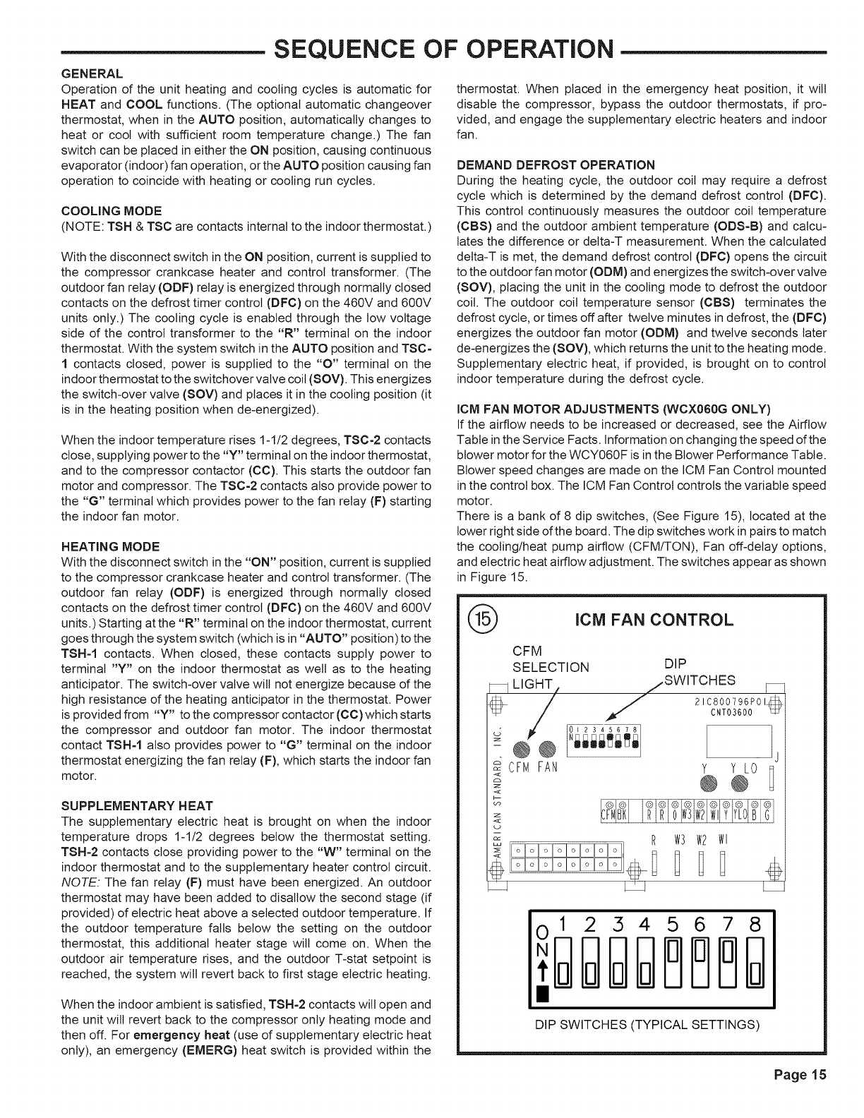
There is a bank of 8 dip switches, (See Figure 15), located at the
lower right side of the board. The dip switches work in pairs to match
the cooling/heat pump airflow (CFM/TON), Fan off-delay options,
and electric heat airflow adjustment. The switches appear as shown
in Figure 15.
®ICM FAN CONTROL
CFM FAN
<
<
CFM
SELECTION DIP
LIG_ .SWITCHES _
/21C800796P01_
._CNT03600 qz
Y Y LO
R W3 W2 Wl
12345678
DIP SWITCHES (TYPICAL SETTINGS)
Page 15
DEMAND DEFROST SYSTEM
DEFROST CONTROL
The demand defrost control measures heat pump outdoor ambient
temperature with a sensor located outside the outdoor coil. A
second sensor located on the outdoor coil is used to measure the
coil temperature. The difference between the ambient and the
colder coil temperature is the difference or detta-T measurement.
This detta-T measurement is representative of the operating state
and relative capacity of the heat pump system. By measuring the
change in delta-T, we can determine the need for defrost. The coil
sensor also serves to sense outdoor coil temperature for termina-
tion of the defrost cycle.
FAULT DETECTION
A fault condition is indicated by the flashing light on the defrost
control inside the heat pump control box.
In normal operation, the defrost control light wilt flash once each
second. If the light is flashing more than once per second or not-at-
all, refer to the service manual for that unit.
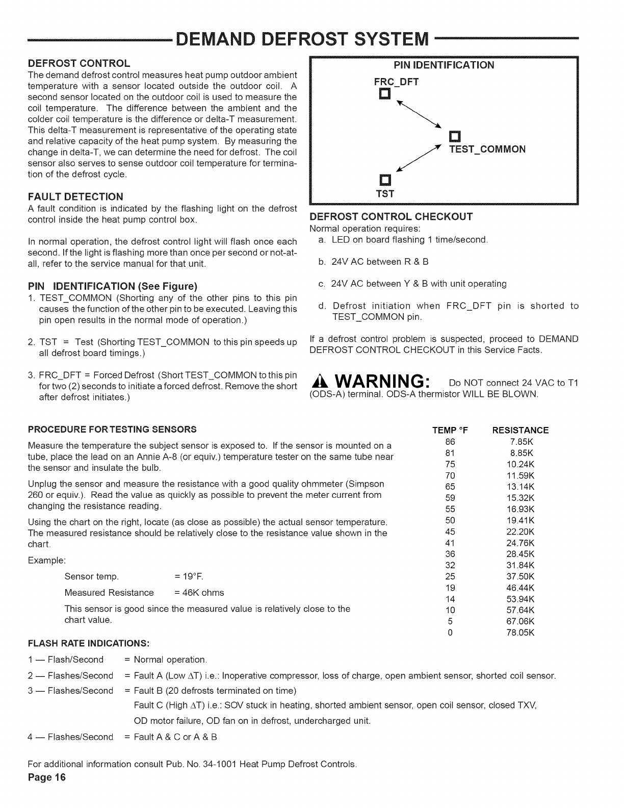
PiN IDENTIFICATION
FRC DFT
[]
S
D
TST
D
TEST COMMON
DEFROST CONTROL CHECKOUT
Normal operation requires:
a. LED on board flashing 1 time/second.
b. 24V AC between R & B
PIN IDENTIFICATION (See Figure)
1. TEST_COMMON (Shorting any of the other pins to this pin
causes the function of the other pin to be executed. Leaving this
pin open results in the normal mode of operation.)
2. TST = Test (Shorting TEST_COMMON to this pin speeds up
all defrost board timings.)
c. 24V AC between Y & B with unit operating
d. Defrost initiation when FRC_DFT pin is shorted to
TEST_COMMON pin.
If a defrost control problem is suspected, proceed to DEMAND
DEFROST CONTROL CHECKOUT in this Service Facts.
3. FRC_DFT = Forced Defrost (Short TEST_COMMON to this pin
for two (2) seconds to initiate a forced defrost. Remove the short
after defrost initiates.)
WARNING: DONOTconnect24VACtoTI
(ODS-A) terminal. ODS-A thermistor WILL BE BLOWN.
PROCEDURE FORTESTING SENSORS
Measure the temperature the subject sensor is exposed to. If the sensor is mounted on a
tube, place the lead on an Annie A-8 (or equiv.) temperature tester on the same tube near
the sensor and insulate the bulb.
Unplug the sensor and measure the resistance with a good quality ohmmeter (Simpson
260 or equiv.). Read the value as quickly as possible to prevent the meter current from
changing the resistance reading.
Using the chart on the right, locate (as close as possible) the actual sensor temperature.
The measured resistance should be relatively close to the resistance value shown in the
chart.
Example:
Sensor temp. = 19°F.
Measured Resistance = 46K ohms
This sensor is good since the measured value is relatively close to the
chart value.
FLASH RATE INDICATIONS:
TEMP °F RESISTANCE
86 7.85K
81 8.85K
75 10.24K
70 11.59K
65 13.14K
59 15.32K
55 16.93K
50 19.41K
45 22.20K
41 24.76K
36 28.45K
32 31.84K
25 37.50K
19 46.44K
14 53.94K
10 57.64K
5 67.06K
0 78.05K
I -- Flash/Second =
2-- Flashes/Second =
3-- Flashes/Second =
Normal operation.
Fault A (Low AT) i.e.: Inoperative compressor, toss of charge, open ambient sensor, shorted coil sensor.
Fault B (20 defrosts terminated on time)
Fault C (High AT) i.e.: SOV stuck in heating, shorted ambient sensor, open coil sensor, closed TXV,
OD motor failure, OD fan on in defrost, undercharged unit.
4--Flashes/Second = FaultA&CorA&B
For additional information consult Pub. No. 34-1001 Heat Pump Defrost Controls.
Page 16
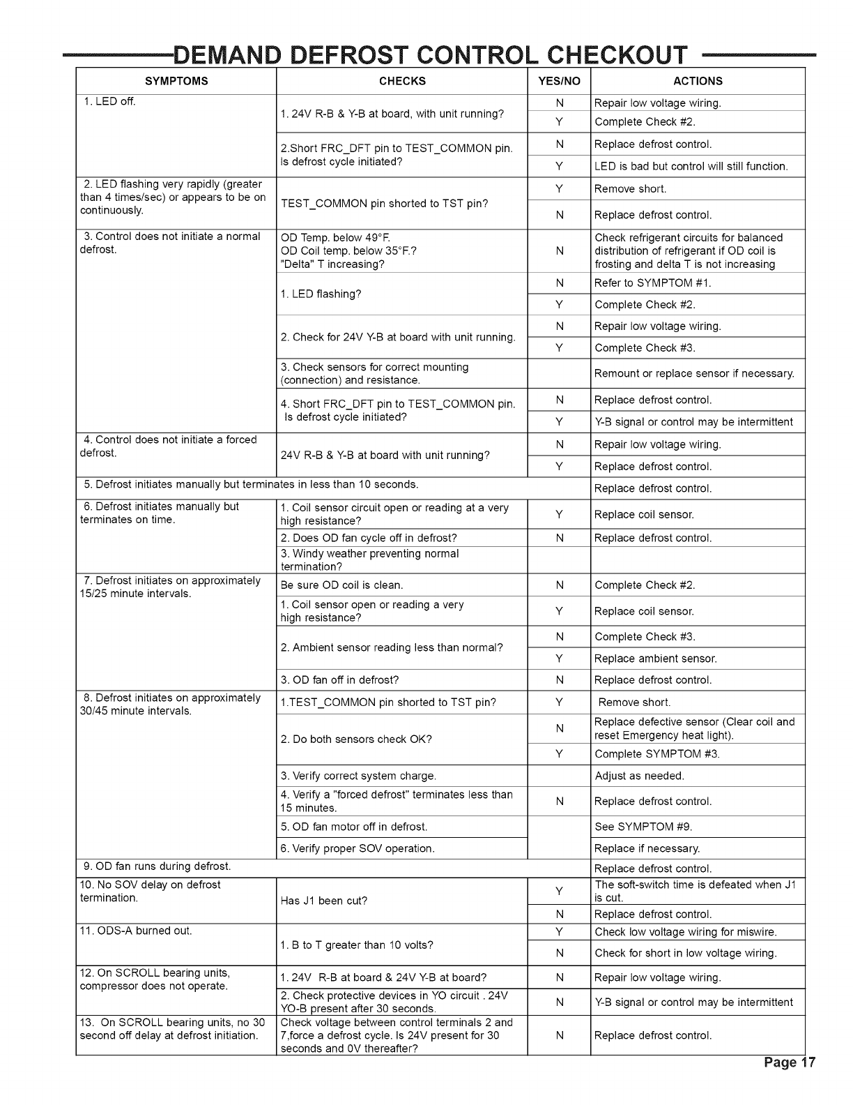
1. LED off.
DEMAND
SYMPTOMS
2. LED flashing very rapidly (greater
than 4 times/sec) or appears to be on
continuously.
3. Control does not initiate a normal
defrost.
DEFROST CONTROL CHECKOUT
CHECKS
1.24V R-B & Y-B at board, with unit running?
2.Short FRC_DFT pin to TEST_COMMON pin.
Is defrost cycle initiated?
TEST_COMMON pin shorted to TST pin?
OD Temp. below 49°E
OD Coil temp. below 35°F.?
"Delta" T increasing?
1. LED flashing?
2. Check for 24V Y-B at board with unit running.
3. Check sensors for correct mounting
(connection) and resistance.
4. Control does not initiate a forced
defrost.
4. Short FRC_DFT pin to TEST_COMMON pin.
Is defrost cycle initiated?
24V R-B & Y-B at board with unit running?
5. Defrost initiates manually but terminates in less than 10 seconds.
6. Defrost initiates manually but
terminates on time.
7. Defrost initiates on approximately
15/25 minute intervals.
8. Defrost initiates on approximately
30/45 minute intervals.
1. Coil sensor circuit open or reading at a very
high resistance?
2. Does OD fan cycle off in defrost?
3. Windy weather preventing normal
termination?
Be sure OD coil is clean.
1. Coil sensor open or reading a very
high resistance?
2. Ambient sensor reading less than normal?
3. OD fan off in defrost?
1.TEST_COMMON pin shorted to TST pin?
2. Do both sensors check OK?
3. Verify correct system charge.
4. Verify a "forced defrost" terminates less than
15 minutes.
5. OD fan motor off in defrost.
6. Verify proper SOV operation.
Has J1 been cut?
1. B to T greater than 10 volts?
9. OD fan runs during defrost.
10. No SOV delay on defrost
termination.
1.24V R-B at board & 24V Y-B at board?
2. Check protective devices in YO circuit. 24V
YO-B present after 30 seconds.
Check voltage between control terminals 2 and
7,force a defrost cycle. Is 24V present for 30
seconds and 0V thereafter?
11. ODS-A burned out.
YES/NO
N
Y
N
Y
Y
N
N
N
Y
N
Y
N
Y
N
Y
Y
N
N
Y
N
Y
N
Y
N
Y
N
Y
N
Y
N
N
N
12. On SCROLL bearing units,
compressor does not operate.
ACTIONS
Repair low voltage wiring.
Complete Check #2.
Replace defrost control.
LED is bad but control will still function.
Remove short.
Replace defrost control.
Check refrigerant circuits for balanced
distribution of refrigerant if OD coil is
frosting and delta T is not increasing
Refer to SYMPTOM #1.
Complete Check #2.
Repair low voltage wiring.
Complete Check #3.
Remount or replace sensor if necessary.
Replace defrost control.
Y-B signal or control may be intermittent
Repair low voltage wiring.
Replace defrost control.
Replace defrost control.
Replace coil sensor.
Replace defrost control.
Complete Check #2.
Replace coil sensor.
Complete Check #3.
Replace ambient sensor.
Replace defrost control.
Remove short.
Replace defective sensor (Clear coil and
reset Emergency heat light).
Complete SYMPTOM #3.
Adjust as needed.
Replace defrost control.
See SYMPTOM #9.
Replace if necessary.
Replace defrost control.
The soft-switch time is defeated when J1
is cut.
Replace defrost control.
Check low voltage wiring for miswire.
Check for short in low voltage wiring.
Repair low voltage wiring.
Y-B signal or control may be intermittent
13. On SCROLL bearing units, no 30
second off delay at defrost initiation. N Replace defrost control.
Page
MAINTENANCE
ROUTINE MAINTENANCE BY OWNER
You can do some of the periodic maintenance functions for
your WCX-G unit yourself; this includes replacing the dispos-
able or cleaning the permanent air filters, cleaning the unit
cabinet, clearing the condenser coil, and conducting ageneral
unit inspection on a regular basis.
Be sure to inspect them at least once each month when
the system is in constant operation. (In new homes, check
the filters every week for the first four (4) weeks.)
MAINTENANCE PERFORMED BY SERVICEMAN--
HEATING SEASON
Complete the unit inspections and service routines described below
at the beginning of each heating season.
• Visually inspect the unit to ensure that the airflow required for
condenser coil is not obstructed from the unit.
• Inspect the control panel wiring to verify that all electrical
connections are tight and that the wire insulation is intact.
If you have disposable-type filters, replace them with new
filters of the same type and size. Do not attempt to clean
disposable filters.
Permanent-type filters can be cleaned by washing them with
a mild detergent and water. Make sure that the filters are
thoroughly dry before re-installing them in the unit (or duct
system).
NOTE: It may be necessary to replace permanent filters
annually if washing fails to clean the filter or if the filter shows
signs of deterioration. Be sure to use the same type and size
as was originally installed.
CONDENSER COIL
Unfiltered air circulates through the unit's condenser coil and
can cause the coil's surface to become clogged with dust, dirt,
etc. To clean the coil, vertically (i.e., with the fins) stroke the
coil surface with a soft-bristled brush.
Be sure to keep all vegetation away from the condenser coil
area.
MAINTENANCE PERFORMED BY SERVICEMAN--
COOLING SEASON
To keep your unit operating safely and efficiently, the manu-
facturer recommends that a qualified serviceman check the
entire system at least once each year and any other time that
you feel one is needed. Your serviceman should examine
these areas of your WCY-F unit:
• filters (for cleaning or replacement)
• motors and drive system components
• gaskets (for possible replacement)
• safety controls (for mechanical cleaning)
• electrical components and wiring (for possible replacement and
connection tightness)
• condensate drain (for cleaning)
• unit duct connections (to see that they are physically sound and
sealed to the unit casing)
• unit mounting support (for structural integrity)
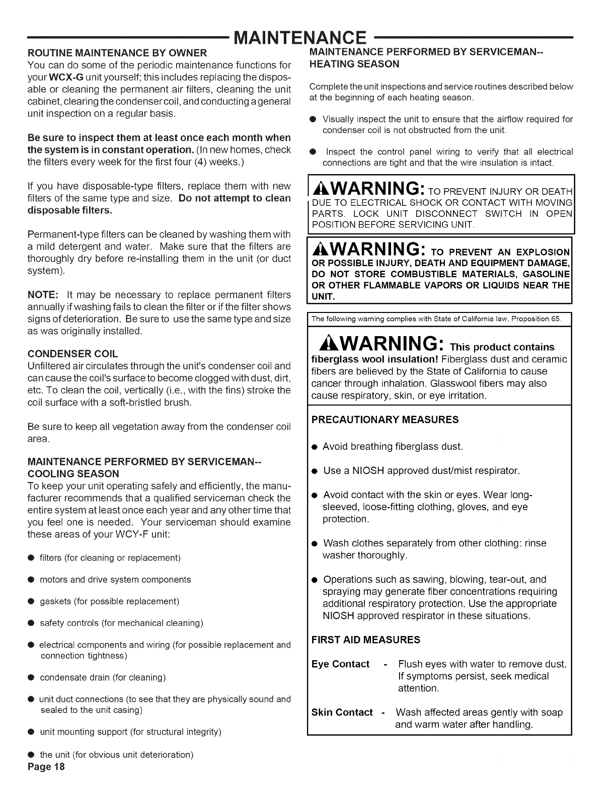
WARNING: TO PREVENT INJURY OR DEATH
DUE TO ELECTRICAL SHOCK OR CONTACT WITH MOVING
PARTS. LOCK UNIT DISCONNECT SWITCH IN OPEN
POSITION BEFORE SERVICING UNIT.
WARNING: TO PREVENT AN EXPLOS,ON I
OR POSSIBLE INJURY, DEATH AND EQUIPMENT DAMAGE,
DO NOT STORE COMBUSTIBLE MATERIALS, GASOLINEI
OR OTHER FLAMMABLE VAPORS OR LIQUIDS NEAR THEI
I
UNIT. l
The following warning complies with State of California law, Proposition 65.
WARNING: This product contains
fiberglass wool insulation! Fiberglass dust and ceramic
fibers are believed by the State of California to cause
cancer through inhalation. Glasswool fibers may also
cause respiratory, skin, or eye irritation.
PRECAUTIONARY MEASURES
•Avoid breathing fiberglass dust.
• Use a NIOSH approved dust/mist respirator.
• Avoid contact with the skin or eyes. Wear long-
sleeved, loose-fitting clothing, gloves, and eye
protection.
• Wash clothes separately from other clothing: rinse
washer thoroughly.
Operations such as sawing, blowing, tear-out, and
spraying may generate fiber concentrations requiring
additional respiratory protection. Use the appropriate
NIOSH approved respirator in these situations.
FIRST AID MEASURES
Eye Contact Flush eyes with water to remove dust.
If symptoms persist, seek medical
attention.
Skin Contact Wash affected areas gently with soap
and warm water after handling.
• the unit (for obvious unit deterioration)
Page 18
LiMiTED WARRANTY
HiGH EFFiCiENCY HEAT PUMP
WCZ, WCY AND WCX
Models Less Than 20 Tons for Residential Use*
(Parts Only)
This limited warranty is extended by American Standard Inc., to the original purchaser and to any
succeeding owner of the real property to which the Heat Pump is originally affixed, and applies to
3roducts purchased and retained for use within the U.S.A. and Canada.
If any part of your Heat Pump fails because of a manufacturing defect within five years from the date of
the original purchase, Warrantor will furnish without charge the required replacement part. Any local
transportation, related service labor, diagnosis calls, refrigerant and related items are not included.
In addition, if the sealed motor-compressor(s) fail(s) or the outdoor coil* should become defective, either
or both events occurring because of a manufacturing defect within the sixth through tenth year from the
date of original purchase, Warrantor will furnish without charge the required replacement compressor
and/or outdoor coil. Any local transportation, related service labor, diagnosis calls, refrigerant and
related items are not included.
*NOTE: If your Heat Pump is installed within one mile of salt water, including but not limited to seacoasts
and inland waterways, your outdoor coil warranty as stated above is limited to five years from the date
of original purchase.
This limited warranty does not cover failure of your Heat Pump if it is damaged while in your
3ossession, damage caused by unreasonable use of the Heat Pump and/or damage from failure to
properly maintain the Heat Pump as set forth in the Use and Care manual (see Proper
Maintenance section).
This limited warranty applies to product installed on or after 10/1/2001 where product is manufactured
after 1/1/2000.This limited warranty is not retroactive to any installations prior to 10/1/2001 or on product
3roduced prior to 2000.
THE LIMITED WARRANTY AND LIABILITY SET FORTH HEREIN ARE IN LIEU OF ALL OTHER
WARRANTIES AND LIABILITIES, WHETHER IN CONTRACT OR IN NEGLIGENCE, EXPRESS OR
IMPLIED, IN LAW OR IN FACT, INCLUDING BUT NOT SPECIFICALLY LIMITEDTO IMPLIED
WARRANTIES OF MERCHANTABILITY AND FITNESS FOR PARTICULAR USE, AND IN NO
EVENT SHALL WARRANTOR BE LIABLE FOR ANY INCIDENTAL OR CONSEQUENTIAL
DAMAGES.
Some states do not allow limitations on how long an implied limited warranty lasts or do not allow the
exclusion or limitation of incidental or consequential damages, so the above limitation or exclusion may
not apply to you.This limited warranty gives you specific legal rights, and you may also have other
rights which vary from state to state.
Parts will be provided by our factory organization through an authorized service organization in your
area listed in the yellow pages. If you wish further help or information concerning this limited warranty,
contact:
American Standard Inc.
Troup Highway
Tyler, TX 75711-9010
Attention: Manager, After Sales Support
GW-624-1802
Page 19
equipment is used for a commercial application. A commercial use is any application where the end
purchaser uses the product for other than personal, family or household purposes.
LiMiTED WARRANTY
HiGH EFFiCiENCY HEAT PUMP
WCZ, WCY, WCX, WCC, WCD, WCH, WCM AND WSC
Models Less Than 20 Tons for Commercial Use*
(Parts Only)
This warranty is extended by American Standard Inc., to the original purchaser and to any
succeeding owner of the real property to which the Heat Pump is originally affixed, and applies to
products purchased and retained for use within the U.S.A. and Canada. There is no warranty
against corrosion, erosion or deterioration.
If any part of your Heat Pump fails because of a manufacturing defect within one year from the
date of the original purchase, Warrantor will furnish without charge the required replacement part.
In addition, if the sealed motor-compressor fails because of a manufacturing defect within the
second through fifth year from the date of original purchase, Warrantor will furnish without charge
the required replacement compressor. Warrantor's obligations and liabilities under this warranty
are limited to furnishing EO.B. Warrantor factory or warehouse replacement parts for Warrantor's
products covered under this warranty. Warrantor shall not be obligated to pay for the cost of lost
refrigerant. No liability shall attach to Warrantor until products have been paid for and then liability
shall be limited solely to the purchase price of the equipment under warranty shown to be
defective.
THE WARRANTY AND LIABILITY SET FORTH HEREIN ARE IN LIEU OF ALL
OTHER WARRANTIES AND LIABILITIES, WHETHER IN CONTRACT OR IN
NEGLIGENCE, EXPRESS OR IMPLIED, IN LAW OR IN FACT, INCLUDING
IMPLIED WARRANTIES OF MERCHANTABILITY AND FITNESS FOR
PARTICULAR USE, AND IN NO EVENT SHALL WARRANTOR BE LIABLE FOR
ANY INCIDENTAL OR CONSEQUENTIAL DAMAGES.
Some states do not allow limitations on how long an implied warranty lasts or do not allow the
exclusion or limitation of incidental or consequential damages, so the above limitation or exclusion
may not apply to you. This warranty gives you specific legal rights, and you may also have other
rights which vary from state to state.
American Standard Inc.
Troup Highway
Tyler, TX 75711-9010
Attention: Manager, After Sales Support
GW-604-4800
* This warranty is for commercial usage of said equipment and not applicable when the equipment
is used for a residential application. Commercial use is any application where the end purchaser
uses the product for other than personal, family or household purposes.
Since The Trane Company has a policy of continuous product and product data
improvement, it reserves the right to change design and specification without notice,
The Trane Company
Unitary Products Group
6200 Troup Highway
Tyler, TX 75707-9010
An American-Standard Company
Page 20
o( )osTechnical Literature -Printed in U.S.A.
