TRENDNET TEW654TR 802.11n Draft 2.0 Three Mode Wireless Pocket AP User Manual Manual Part 1
TRENDNET, INC. 802.11n Draft 2.0 Three Mode Wireless Pocket AP Manual Part 1
TRENDNET >
Contents
- 1. Manual Part 1
- 2. Manual Part 2
Manual Part 1

Wireless Travel Router2Wireless Travel Router2
Table of Contents
CHAPTER 1: PRODUCT OVERVIEW
1.1 Features ..............................................................................................................5
1.2 Package Contents ...............................................................................................6
1.3 Hardware Overview .............................................................................................7
1.3.1 LED Indicators ..........................................................................................7
1.3.2 Connectors ................................................................................................8
1.4 Travel Router Modes ...........................................................................................9
1.4.1 Switching Modes .......................................................................................10
1.5 Making Connections ............................................................................................11
1.5.1 Connecting the Power Adapter .................................................................11
1.5.2 Connecting the Dual Head USB Cable .....................................................11
1.5.3 Connecting the Ethernet Cable .................................................................12
1.6 System Requirements .........................................................................................12
1.6.1 Conguring Connections ...........................................................................12
CHAPTER 2: AP MODE
2.1 Installation ...........................................................................................................14
2.2 Web-Based Conguration ...................................................................................15
2.2.1 Wizard .......................................................................................................16
2.2.2 Setup .........................................................................................................18
Wireless Network Settings ........................................................................18
Local Area Network (LAN) Settings ..........................................................21
Dynamic IP (DHCP) .................................................................................21
Static IP ....................................................................................................21
Wi-Fi Protected Setup (WPS) Settings .....................................................22
2.2.3 Advanced ..................................................................................................23
Advanced Wireless Network Settings .......................................................23
Access Control ..........................................................................................24
2.2.4 System ......................................................................................................25
Admin ........................................................................................................25
Settings .....................................................................................................25
Firmware ...................................................................................................26
Time ..........................................................................................................26

Wireless Travel Router 3Wireless Travel Router 3
2.2.5 Status ........................................................................................................27
Device Info ................................................................................................27
Logs ..........................................................................................................27
Statistics ....................................................................................................27
Wireless ....................................................................................................27
CHAPTER 3: CLIENT MODE
3.1 Installation ...........................................................................................................29
3.1.1 Infrastructure Mode ...................................................................................29
3.1.2 Ad-Hoc Mode ............................................................................................30
3.2 Web-Based Conguration ...................................................................................31
3.2.1 Wizard .......................................................................................................32
3.2.2 Setup .........................................................................................................34
Wireless AP/ AP Client Settings ................................................................34
Local Area Network (LAN) Settings ..........................................................39
Dynamic IP (DHCP) ..................................................................................39
Static IP .....................................................................................................39
Wi-Fi Protected Setup (WPS) Settings .....................................................40
3.2.3 Advanced ..................................................................................................40
Advanced Wireless Network Settings .......................................................40
3.2.4 System ......................................................................................................41
Admin ........................................................................................................41
Settings .....................................................................................................41
Firmware ...................................................................................................42
Time ..........................................................................................................42
3.2.5 Status ........................................................................................................43
Device Info ................................................................................................43
Logs ..........................................................................................................43
Statistics ....................................................................................................43
CHAPTER 4: ROUTER MODE
4.1 Installation ...........................................................................................................45
4.2 Web-Based Conguration ...................................................................................46
4.2.1 Wizard .......................................................................................................47
4.2.2 Setup .........................................................................................................50
Wireless Network Settings ........................................................................50

Wireless Travel Router4Wireless Travel Router4
Local Area Network (LAN) Settings ..........................................................53
Wide Area Network (WAN) Settings ..........................................................54
Dynamic IP (DHCP) ..................................................................................54
Static IP .....................................................................................................54
PPPoE ......................................................................................................55
PPTP .........................................................................................................56
L2TP .........................................................................................................57
Wi-Fi Protected Setup (WPS) Settings .....................................................58
Dynamic DNS Settings .............................................................................59
4.2.3 Advanced ..................................................................................................60
Access Control ..........................................................................................60
IP Filter ......................................................................................................61
Parental Control ........................................................................................62
Virtual Server ............................................................................................63
Special AP .................................................................................................64
DMZ ..........................................................................................................65
Firewall Settings ........................................................................................66
Advanced Network Settings ......................................................................67
Advanced Wireless Network Settings .......................................................68
4.2.4 System ......................................................................................................69
Admin ........................................................................................................69
Settings .....................................................................................................69
Firmware ...................................................................................................70
Time ..........................................................................................................70
Ping Test ...................................................................................................71
4.2.5 Status ........................................................................................................71
Device Info ................................................................................................71
Statistics ....................................................................................................72
Wireless ....................................................................................................72
Logs ..........................................................................................................72
Appendix A: Regulatory & Safety Information ...........................................................73
Appendix B: Specications .......................................................................................77
Appendix C: Limited Warranty ..................................................................................78

Wireless Travel Router 5
Product
Overview
1
Congratulations on your purchase of the 3-in-1 Travel Router. The Travel Router
functions as an Access Point for wireless connections, an Access Point Client for
wired devices to have wireless connections, and a Router to share resources such as
computers, printers, les and other devices.
This User Manual will guide you on how to install and set up the Travel Router. Read
it carefully and keep it for future reference.
1.1 Features
3-in-1 Operation Mode: Supports AP, Router, and AP Client modes
Smallest Networking Device
Fast Wireless Networking: Provides fast data rate connection up to 300Mbps for
802.11n devices
Full range compatibility: Compatible with IEEE 802.11n, 802.11g, 802.11b and
802.3u devices
Low Power Consumption: Consumes less than 2.5 watts
USB Bus Powered: Provides better mobility.
Quick and Easy Setup with Web-based Management Utility
Strong Network Security - Supports the following features:
•
•
•
•
•
•
•
•
WPA, WPA-PSK, WPA2, and WPA2-PSK security standars
WPS button for Wi-Fi WPS conguration
PPPoE/PPTP/L2TP protocol for DSL connections
Firewall protection
→
→
→
→
Wireless Travel Router6Wireless Travel Router6
1. PRODUCT OVERVIEW
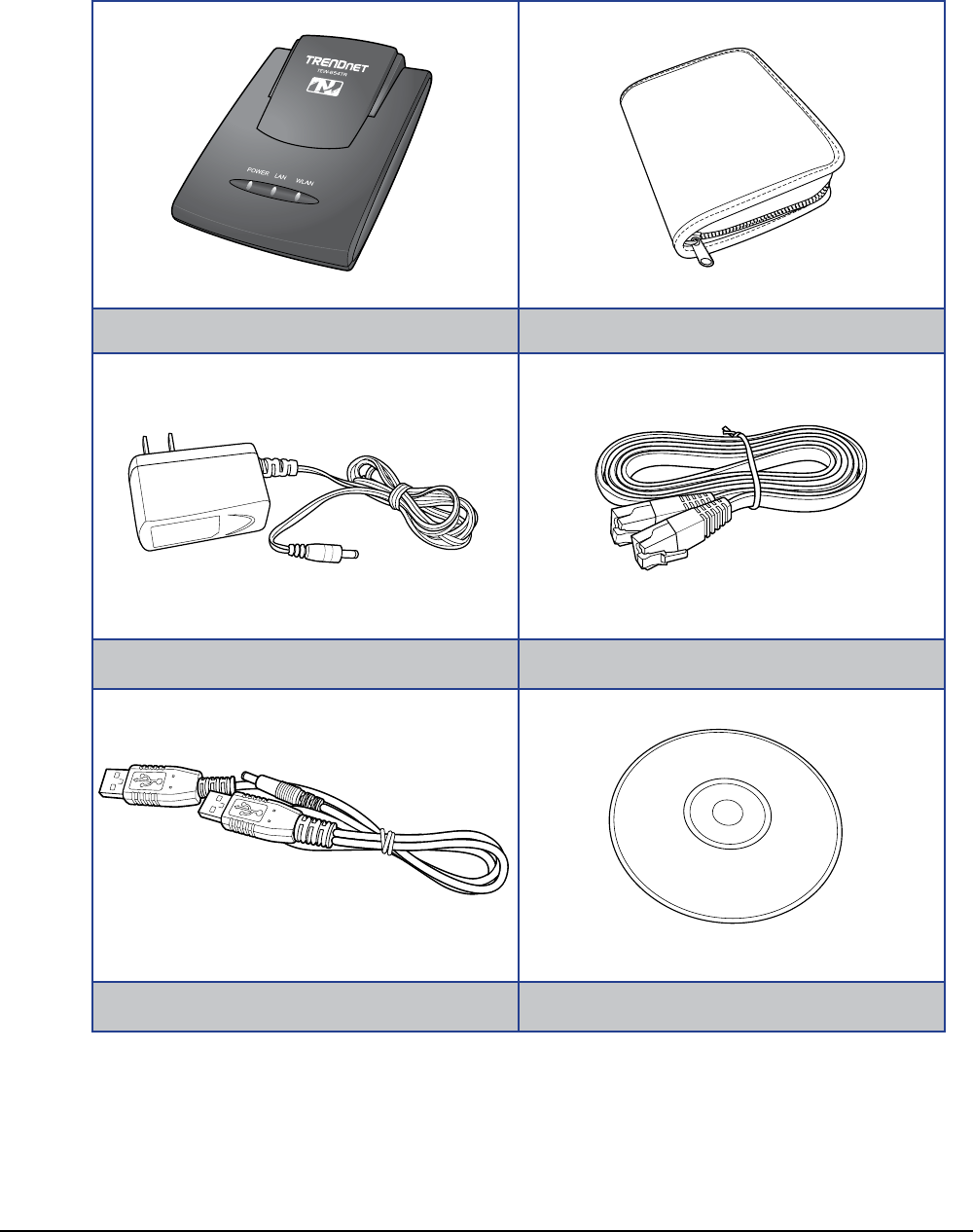
1.2 Package Contents
Check if your package comes with the following items. If any of them is missing or
appears damaged, please contact your retailer.
Travel Router Pouch
Power Adapter Ethernet Cable
Dual Head USB Cable CD-ROM
Wireless Travel Router 7Wireless Travel Router 7
1. PRODUCT OVERVIEW
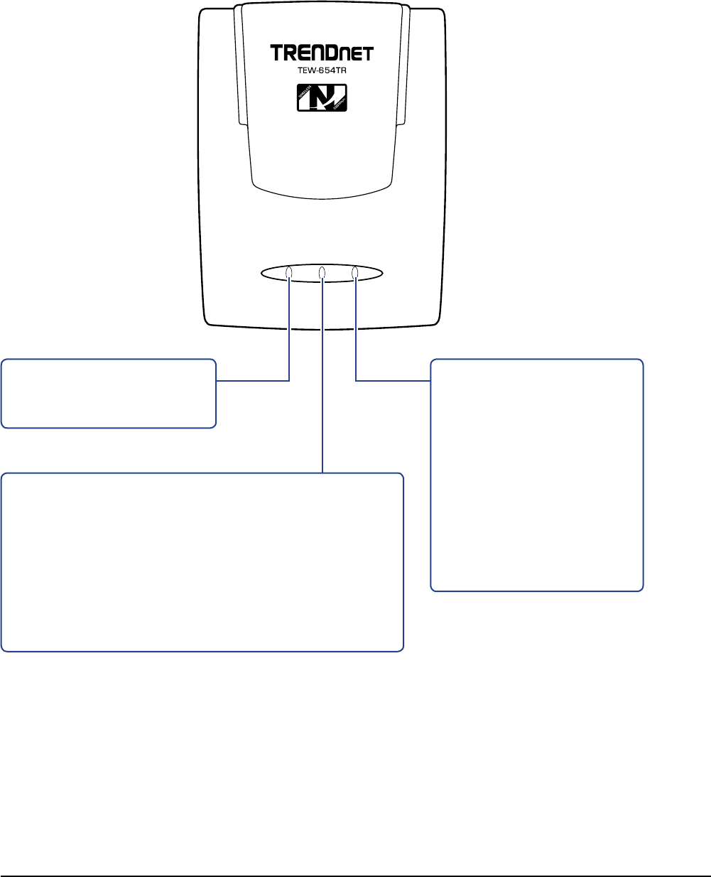
POWER WLANLAN
Power LED
Lights when the power is
connected.
WLAN / WPS LED
Flashes to indicate activity.
GREEN
Blinks when a wireless
device is connected.
Blinks when data
transfer is in progress.
AMBER
Blinks when WPS is
enabled.
•
•
•
LAN / WAN LED
GREEN (solid)
Lights when LAN/WAN port is connected to a DSL
or cable modem successfully.
GREEN (blinks)
Blinks when transmitting or receiving data through
the LAN / WAN connection.
•
•
1.3 Hardware Overview
1.3.1 LED Indicators
Wireless Travel Router8Wireless Travel Router8
1. PRODUCT OVERVIEW
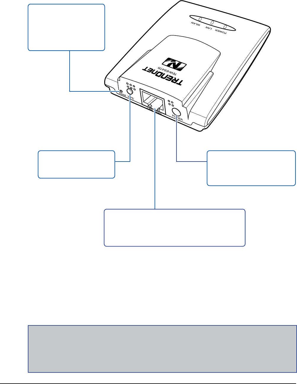
1.3.2 Connectors
Note:
A wireless network normally requires a network name (SSID) and WPA security key to prevent
unwanted access to the network. This process requires users to have knowledge of WiFi devices
and their congurations. But with WPS enabled, the network name (SSID) and WPA security key of
the devices are automatically congured.
WPS Button
Press to enable Wi-Fi
Protected Setup.
LAN / WAN Port
Connect to a wired network or a DSL modem,
a computer, or other device such as a switch
or a hub using the Ethernet cable.
Reset Button
Press and hold for 5
seconds to reboot the
device and restore the
factory default settings.
Power Port
Connect the power adapter
or the USB cable to this
port.
Wireless Travel Router 9Wireless Travel Router 9
1. PRODUCT OVERVIEW
1.4 Travel Router Modes
Before using the travel router, determine the type of mode you want to use:
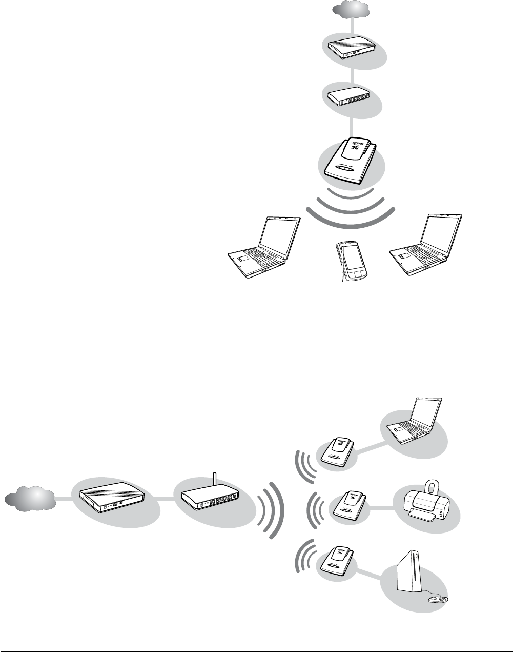
Access Point (AP) Mode
With AP mode, you can use the
travel router as an access point for
wireless clients to connect to the
local area network (LAN) and to
other wireless clients.
•
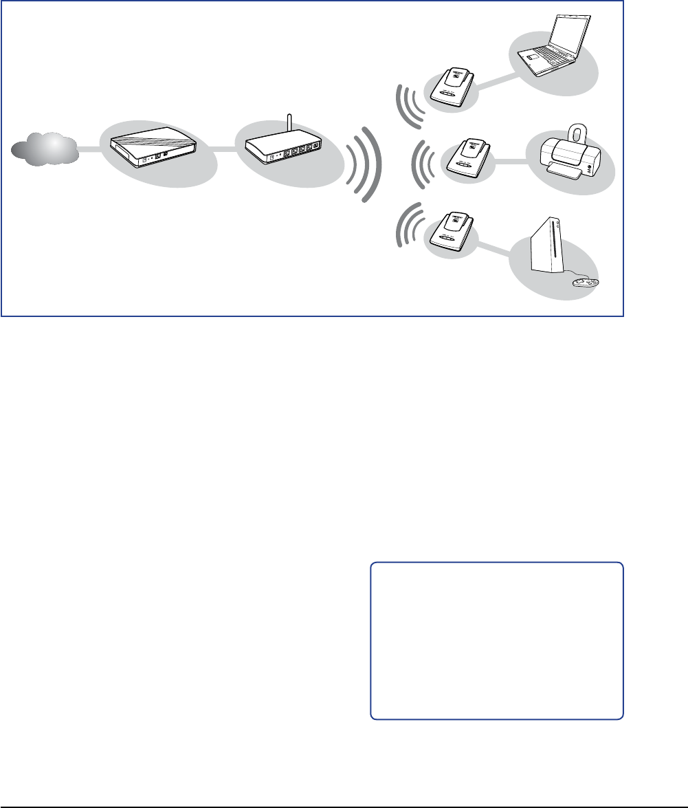
Client Mode
Switch to this AP-Client mode to connect a device to the travel router using an RJ-
45 cable and use the travel router as a wireless adapter. This mode enables the
Ethernet-connected device to have wireless function over a network.
•
Internet
ADSL /
Cable Modem
WLAN AP /
Router
Wireless Station
Printer
Game Console
Internet
DSL /
Cable Modem
Wireless Station
Mobile PDA
Wireless Station
Broadband
Router
Wireless Travel Router10 Wireless Travel Router10
1. PRODUCT OVERVIEW
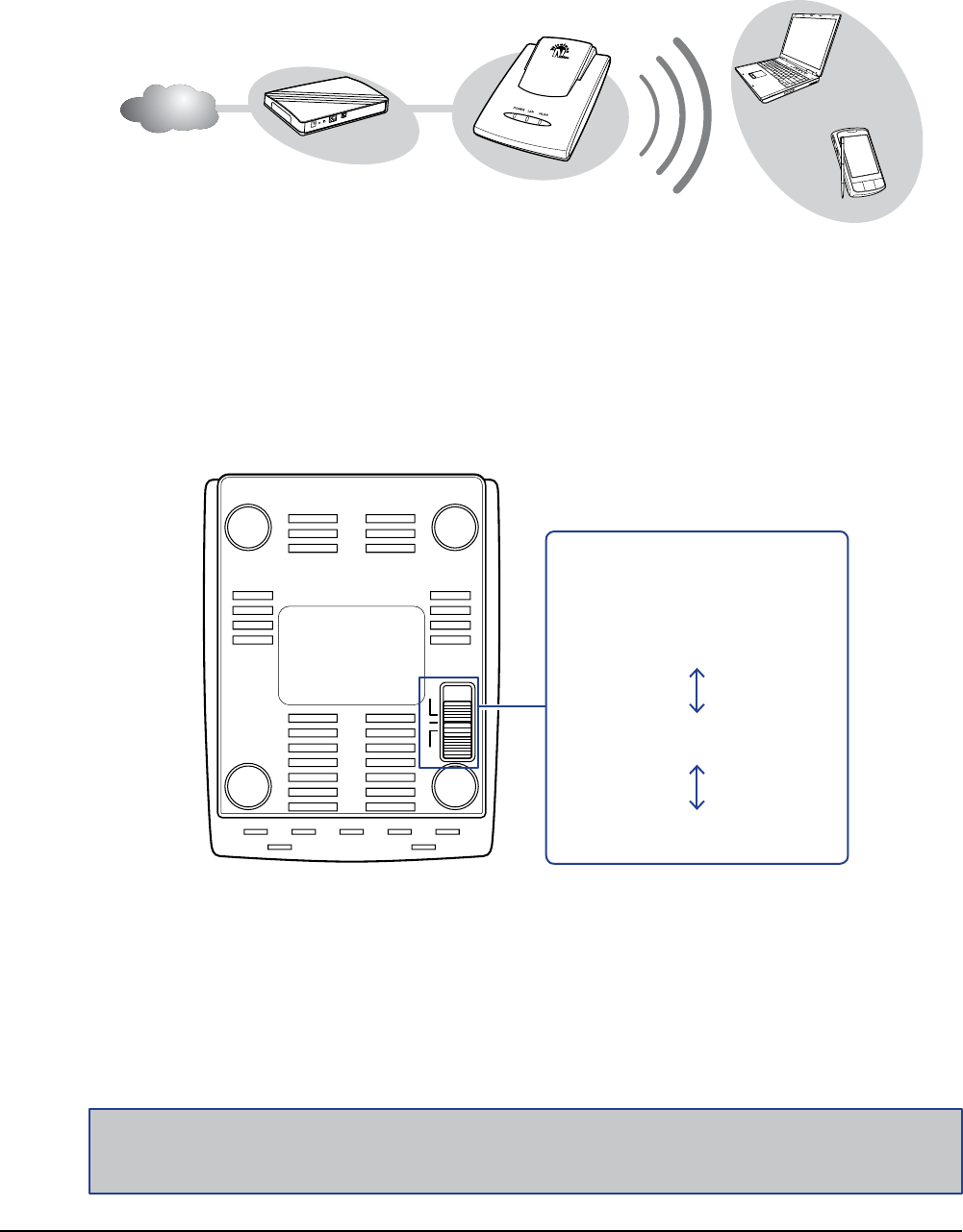
Note:
Make sure to unplug the power source from the power port rst before switching modes.
AP RT
Client
Mode Switch
Adjust the switch to change
modes:
AP
Client
Router
1 Unplug the power source (power adapter or USB cable) if it is connected.
2 Adjust the switch to desired mode.
3 Re-connect the power source to the power port.
1.4.1 Switching Modes
Use the mode switch at the bottom of the travel router to change modes.
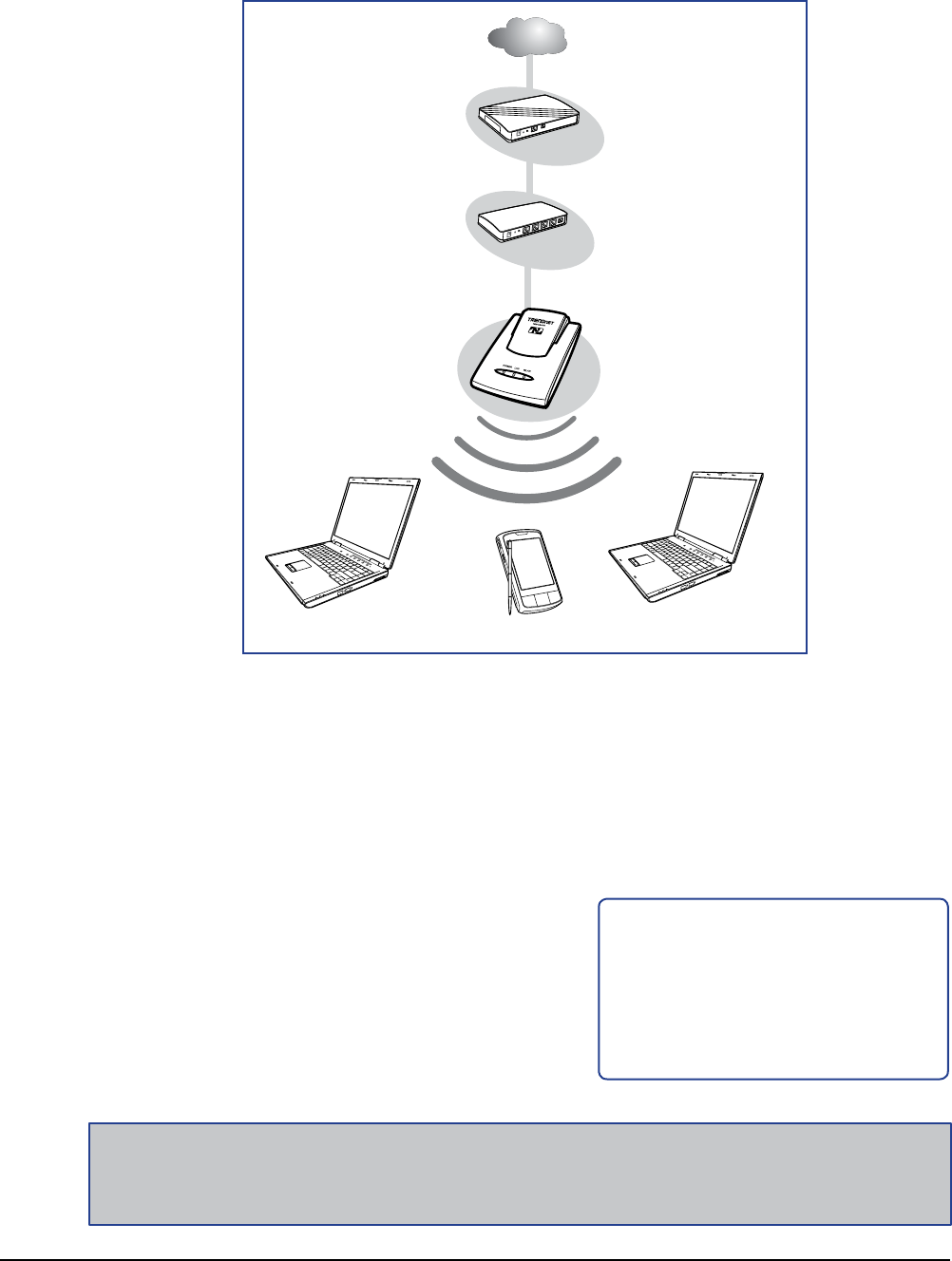
Router Mode
Use this mode to connect the travel router to a DSL or cable modem. With this
mode, wireless clients connect to the Internet through the travel router using one
account and one IP address.
•
Internet
ADSL /
Cable Modem
Wireless Station
Mobile PDA
Wireless Travel Router 11Wireless Travel Router 11
1. PRODUCT OVERVIEW
1.5 Making Connections
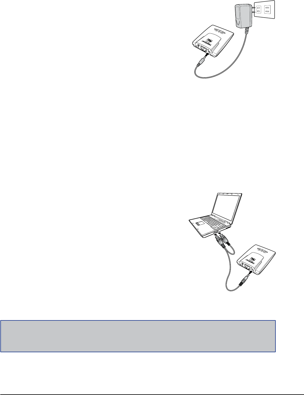
1.5.1 Connecting the Power Adapter
Use the power adapter to directly connect to a
power outlet.
1 Connect the power adapter to the power
port of the travel router.
2 Plug the power adapter to an outlet or power
strip.
1.5.2 Connecting the Dual Head USB Cable
1 Connect the two heads of the USB cable to
your computer.
2 Plug the other end to the power port of the
travel router.
Some computers have over-current protection capability. This means that when the
current of a USB port goes over 500mA, the connected device will not be accessed
by the computer. To avoid this risk, use the dual head USB cable supplied with your
travel router.
To connect, follow the steps below:
Note:
Make sure you connect the dual head USB cable to the computer rst before connecting the travel
router.
Wireless Travel Router12
Wireless Travel Router12
1. PRODUCT OVERVIEW
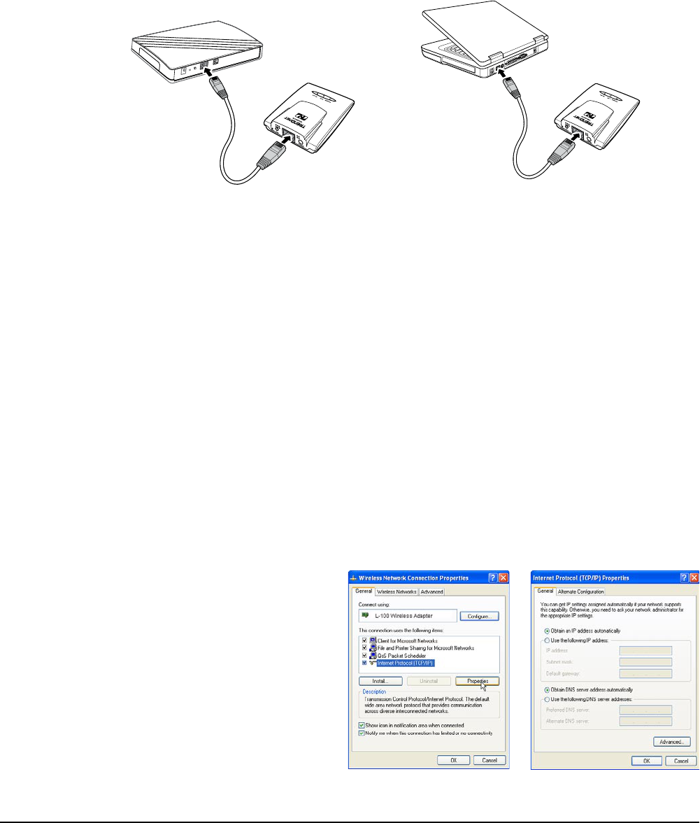
Use the Ethernet (RJ-45) cable to connect to a computer for wired connection or
connect to a DSL or cable modem for internet connection.
1 Connect one end of the Ethernet cable to your computer or a DSL or cable
modem.
2 Plug the other end to the LAN port of the travel router.
1.5.3 Connecting the Ethernet Cable
Cable modem connection Wired computer connection
1.6 System Requirements
Operating systems: Windows XP, Vista
Microsoft Internet Explorer 5.5 or higher
At least one RJ-45 Ethernet network
•
•
•
1.6.1 Conguring Connections
To properly detect the connections, congure your computer’s network settings rst.
The following instructions are based on Windows XP. Non-Windows XP users will
see similar screens.
1 For Windows XP, click Start > Control Panel > Network Connections. Right
click on a connection, then select Properties.
2 Highlight Internet Protocol
(TCP/IP), then click
Properties.
3 Click Obtain an IP address
automatically and Obtain
DNS server address
automatically.
4 Click OK and OK again.

Wireless Travel Router 13
AP Mode
2
Before You Begin
With AP mode, you can use the travel router as an access point of your wireless
device.
Checklist
A valid network or Internet connection.
A DSL / cable modem provided by the ISP as part of the broadband connection
installation.
A broadband router that connects to the DSL / cable modem for internet
connection sharing.
√
√
√
You need to connect...
Connect the travel router to your router or network that has a DHCP server. The
travel router will obtain an IP address from the network automatically.
Connect the LAN port of the travel router to the LAN port on your network then
plug in the power adapter.
Use wireless adapters to connect to the ravel router (default SSID TRENDnet654).
•
•
•
Wireless Travel Router14 Wireless Travel Router14
2. AP MODE
2.1 Installation
Internet
DSL /
Cable Modem
Wireless Station
Mobile PDA
Wireless Station
Broadband
Router
Network Diagram
The following LED
indicators should be lit...
Power LED (solid)
LAN LED (solid)
√
√
1 Adjust the switch to AP mode.
2 Connect one end of the RJ-45 cable to the travel router and the other end to
the DSL or cable modem.
3 Turn on or plug in the DSL / cable modem and the broadband router.
4 Connect the power adapter to the travel router and plug to an outlet or power
strip. Wait for the travel router to boot.
5 Check the LED indicators to verify
connection.
6 Enable the wireless function of the
wireless clients or devices.
Note:
Make sure you remove the power source from the travel router rst before adjusting the mode
switch.
Wireless Travel Router 15Wireless Travel Router 15
2. AP MODE
2.2 Web-Based Conguration
After making all the required connections, congure the travel router using the web-
based conguration utility.
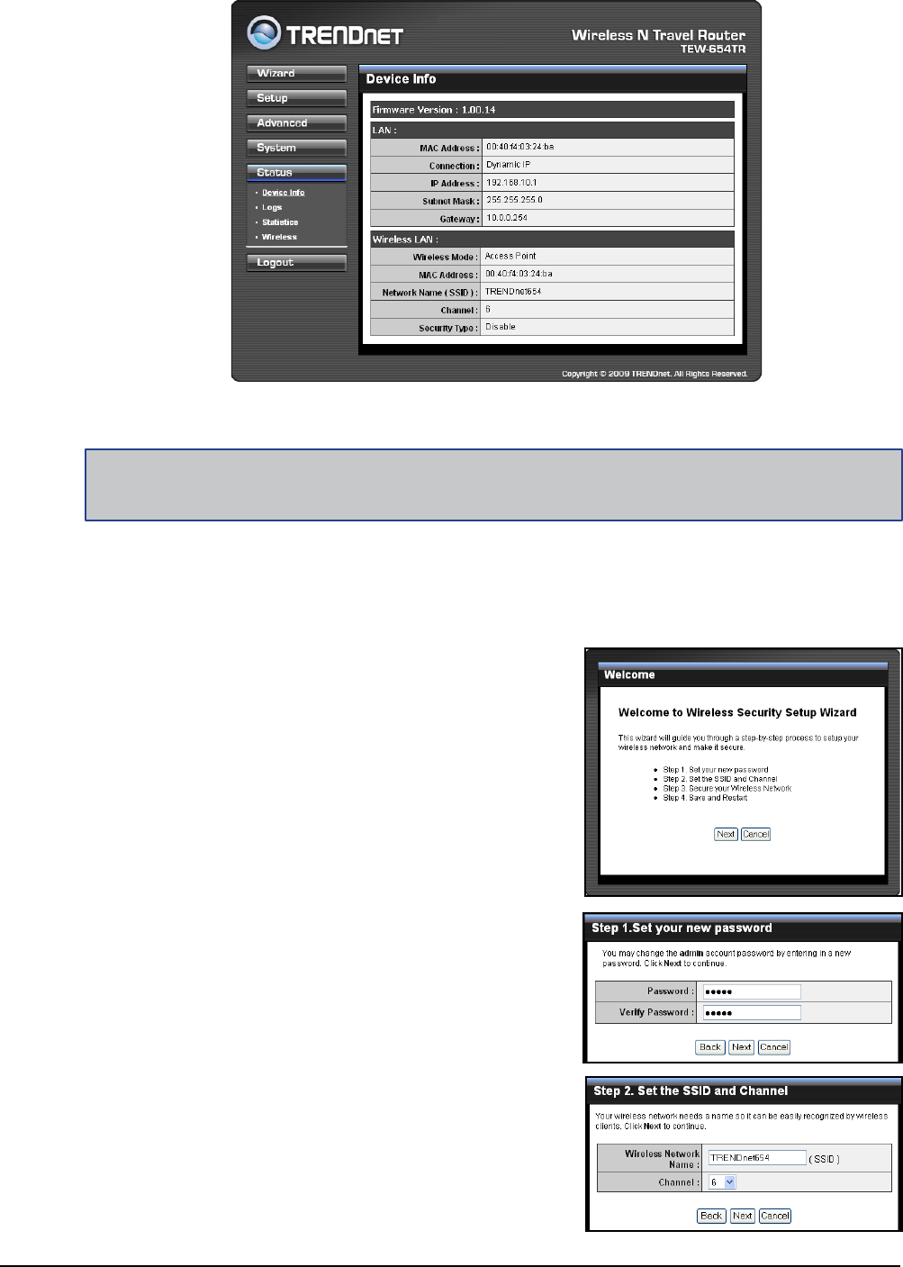
How to Access the Conguration Utility
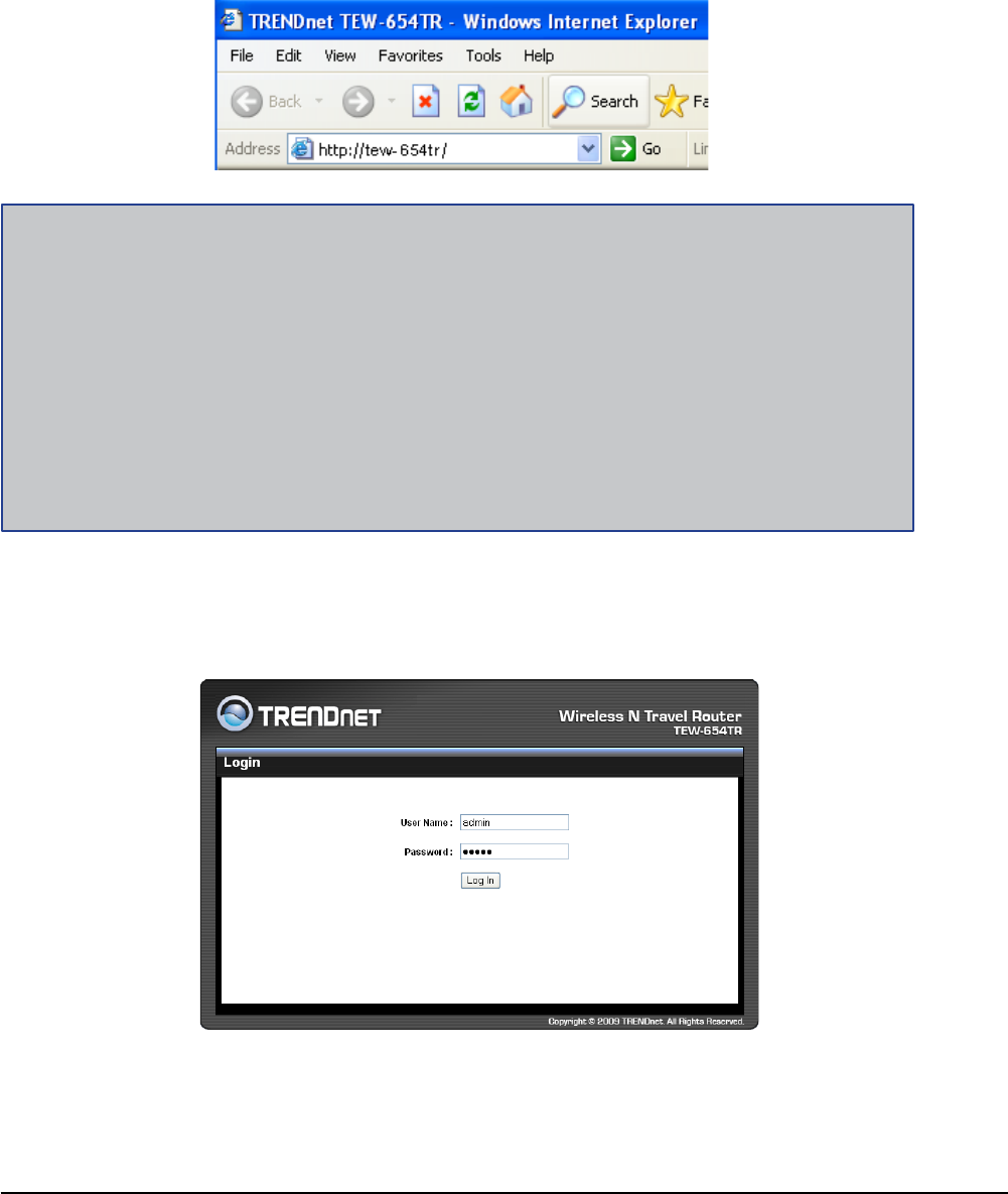
1 Open a web-browser and enter the default address: http://tew-654tr/.
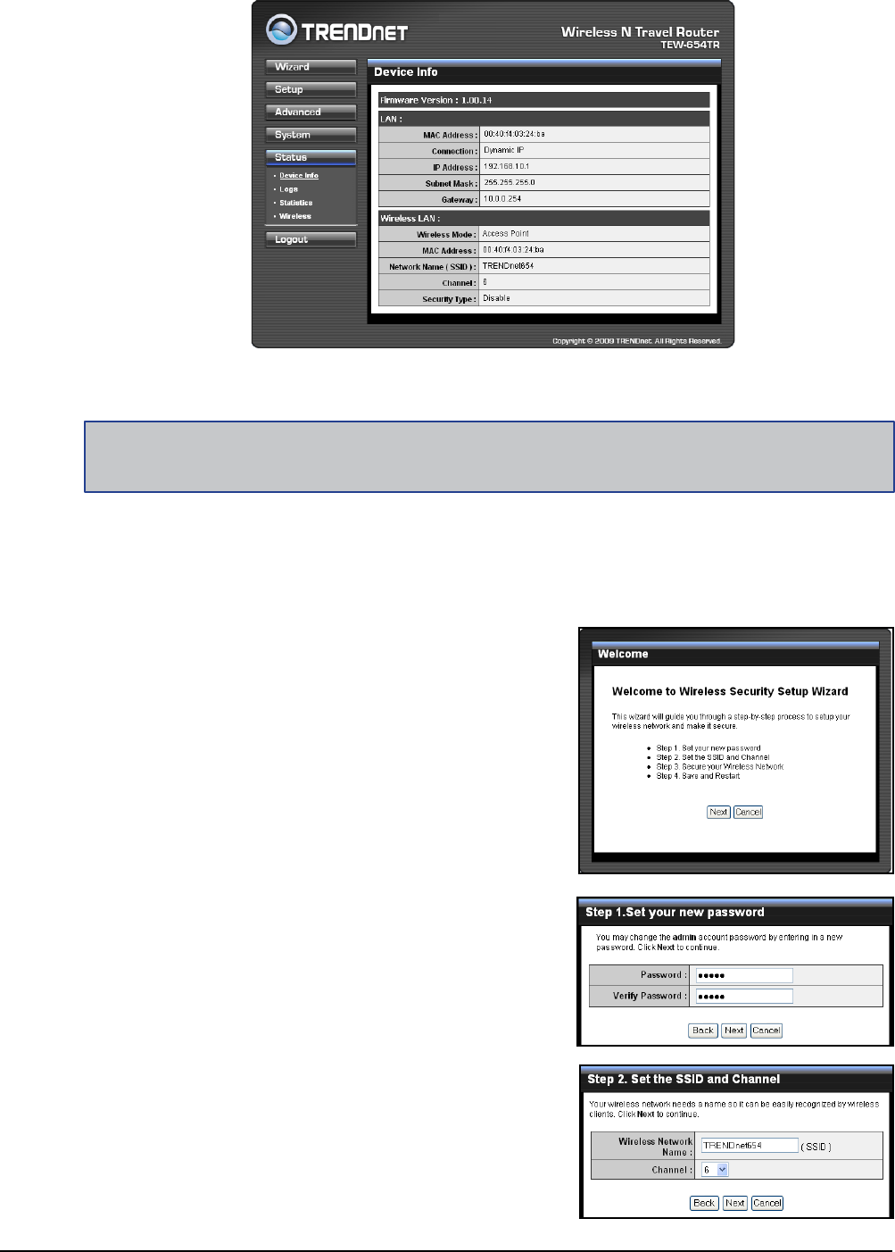
2 Enter the default User Name and Password: admin.
Notes:
You can also access the web-based conguration by any of the following ways:
1. If your LAN connection uses DHCP, the travel router can obtain an IP address from the DHCP
server. You can either enter that IP address or the default address http://tew-654tr/ on the
browser’s address eld to open the web-based conguration utility.
2. If your LAN connection uses Static IP, You can either enter http://tew-654tr/ or that static IP
address on the browser’s address eld. The default IP address is 192.168.10.1.
If you cannot access the conguration utility:
Disable the Internet security software on the computer. The rewall may block access to the
conguration page. Check the software rewall documentation for help.
•
Wireless Travel Router16 Wireless Travel Router16
2. AP MODE
2.2.1 Wizard
Click the Wizard button to congure the travel router using the setup wizard.
1 Click Next to continue.
2 Create a new Password, then click
Next to continue.
3 Create a new Wireless Network Name
and select the Channel (6 by default).
Click Next to continue.
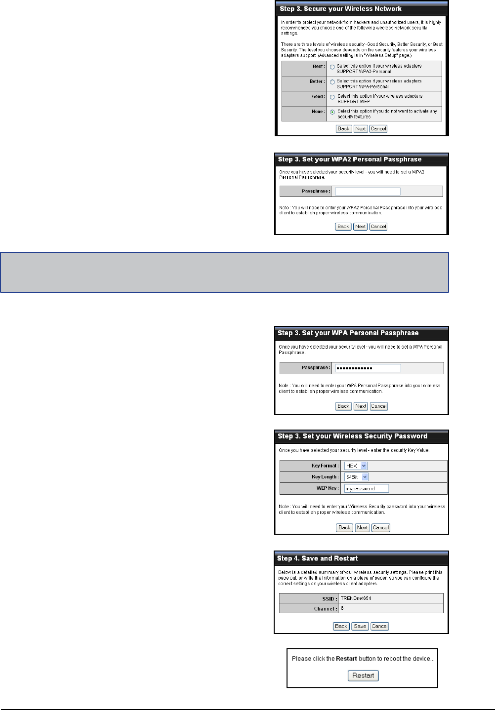
After login, the Status > Device Info page is displayed.
Note:
For novice users, it is recommended to use the Setup Wizard to congure the travel router.
To access a page, click the buttons on the right.
To logout, click Logout.
Wireless Travel Router 17Wireless Travel Router 17
2. AP MODE
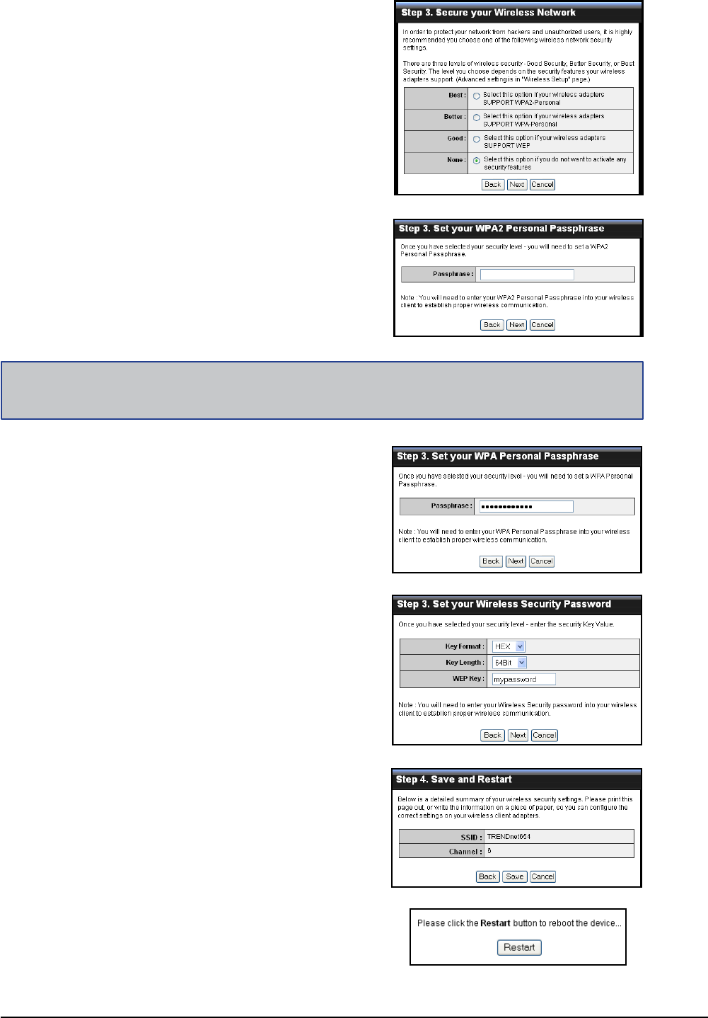
5 The wireless security setting is displayed.
Take note of the information then click
Save.
The information shown varies depending
on the selected security level.
6 Click Restart to reboot the access point
and the device.
If you select Better...
Enter the Passphrase, then click Next to
continue.
Skip to step 5.
If you select Good...
Select the Key Format and Key Length.
Enter the WEP Key, then click Next to
continue.
4 Select the type of security, then click
Next to continue.
If you select None, skip to step 5.
If you select Best...
Enter the Passphrase, then click Next to
continue.
Skip to step 5.
Note:
The Passphrase must be 8-63 ASCII characters or 64 hexadecimal characters.
Wireless Travel Router18 Wireless Travel Router18
2. AP MODE
2.2.2 Setup
The Setup menu allows you to congure basic router settings. Click the Setup button
then the submenu to view page.
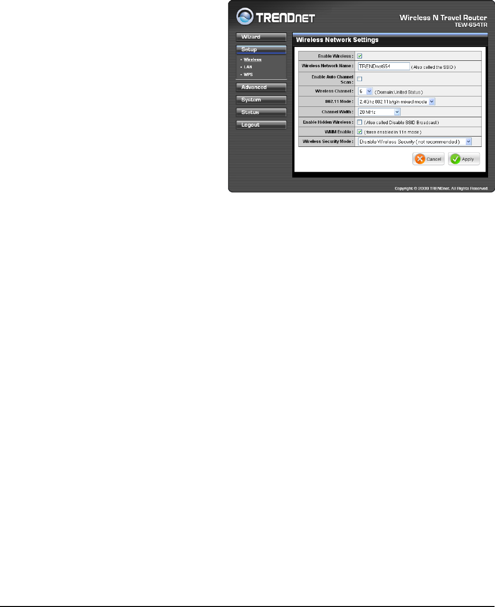
Wireless Network Settings
Enable Wireless
Check the box to enable
wireless function. Uncheck to
disable it.
Wireless Network Name
The name of your wireless
network, also called Service Set
Identier (SSID).
Enter up to 32 characters.
Enable Auto Channel Scan
Auto channel scan selects the
channel with the least amount of
interference. Check to enable auto channel scan.
Wireless Channel
Manually select the channel from the list. By default, the channel is set to 6. If Enable
Auto Channel Scan is checked, this box is grayed out.
802.11 Mode
Limit the type of wireless clients to allow connection with. Select any of the following
modes if your clients are:
2.4Ghz 802.11b/g mixed mode: a mix of 802.11b and 11g wireless devices.
2.4Ghz 802.11b/g/n mixed mode: a mix of 802.11b, 11g, 11n wireless devices.
2.4Ghz 802.11n only mode: all 802.11n wireless devices.
Channel Width
Select the appropriate channel width:
20 MHz (Default): Select if your wireless clients are not 802.11n.
Auto 20/40 MHz: Select if your wireless clients are a mix of 802.11b, 11g, 11n
wireless clients. If you are not sure which wireless clients you are using, select
Auto.
Enable Hidden Wireless
Check to hide the SSID of your wireless network to be broadcasted when wireless
clients scan for wireless networks. To display the router’s SSID, keep the box
unchecked (default).
WMM Enable
Wi-Fi Multimedia (WMM) improves the quality of video and voice applications
•
•
•
•
•
Wireless Travel Router 19Wireless Travel Router 19
2. AP MODE
transmitted over a wireless network. This function is commonly used with multimedia
applications such as a game console. Check the box to enable WMM.
Wireless Security Mode
Select the security level for your wireless network. Select the wireless security mode
from the list:
Disable Wireless Security: (Default) Select if you do not want to use any wireless
security.
Enable WEP Wireless Security (basic)
Enable WPA Wireless Security (enhanced)
Enable WPA-2 Wireless Security (enhanced)
Enable WPA-Auto Wireless Security (enhanced): Select if you are unsure which
WPA wireless security to use.
The required settings vary depending on the selected mode.
•
•
•
•
•
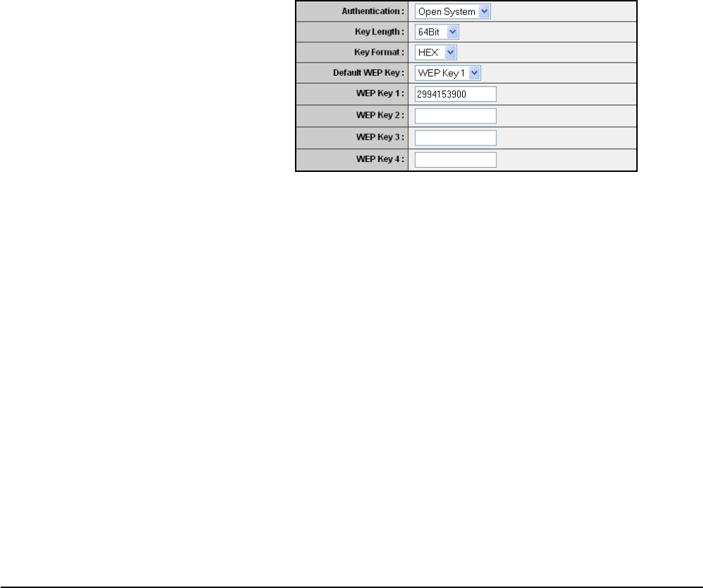
WEP
WEP (Wired Equivalent Privacy) is the basic encryption method. With WEP
encryption, all wireless clients must enter the same key to connect to the access
point.
Authentication
Select the type of authentication:
Open system: Allows public
access to the travel router via
wireless communications.
Shared Key: Requires users
to enter the same WEP key
to exchange data with other
wireless devices.
Auto: Select Auto if you are
•
•
•
unsure which authentication suits best for your wireless clients.
Key Length
Select the key length or the level of encryption:
64Bit: Select to enter 10 hexadecimal characters with any combination of 0-9 or
A-F
128Bit: Select to enter 26 hexadecimal characters with any combination of 0-9
or A-F
Key Format
Select the key format:
ASCII: Select to enter ASCII characters.
HEX: Select to enter hexadecimal characters.
Default WEP Key
The travel router supports up to 4 sets of WEP keys. Select which WEP Key is
used as the default key from the list.
•
•
•
•
Wireless Travel Router20 Wireless Travel Router20
2. AP MODE
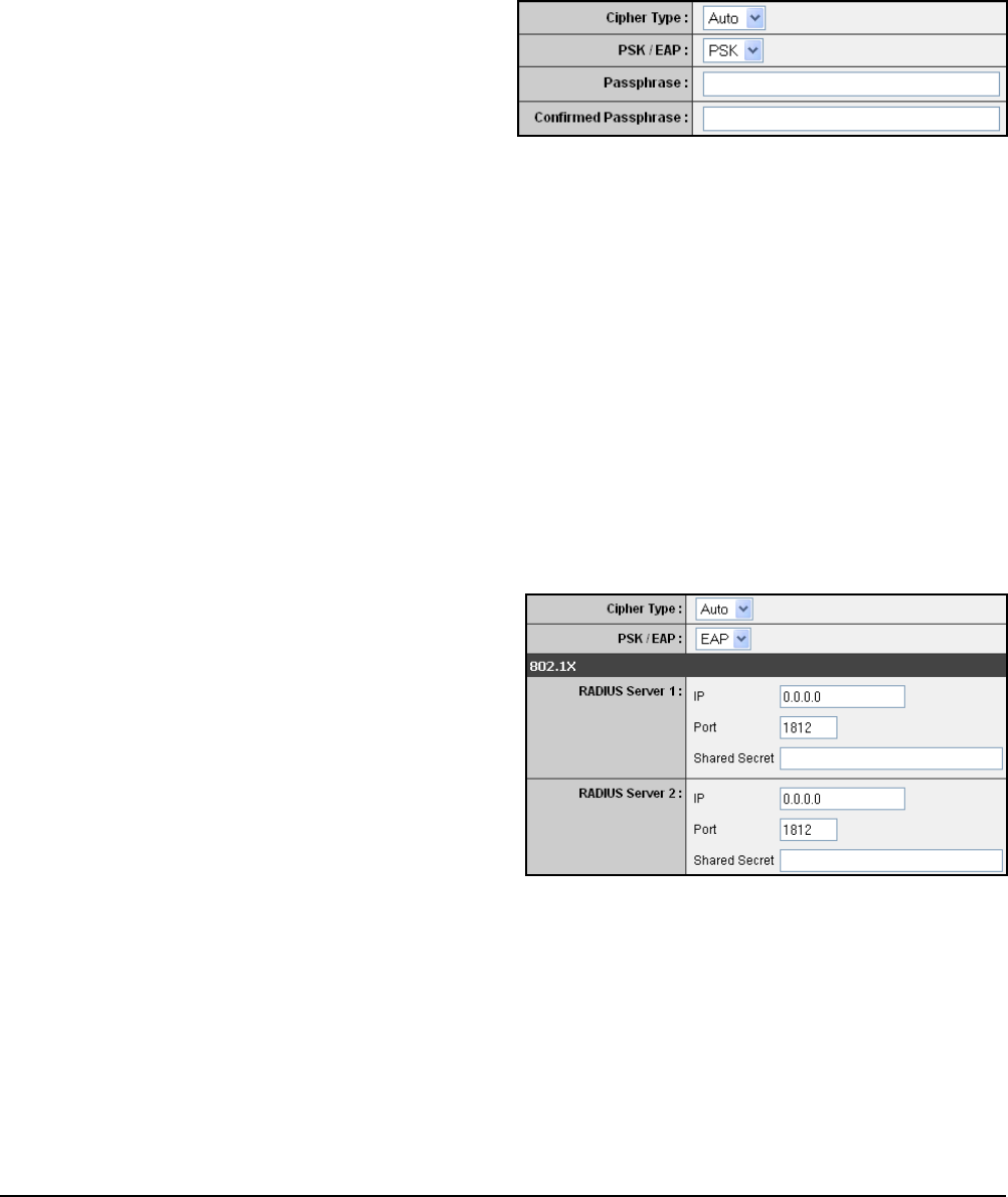
WPA / WPA-2 / WPA-Auto
WPA (Wi-Fi Protected Access) uses high grade encryption and authentication
which is designed to improve WEP encryption. WPA / WPA-2 / WPA-Auto uses a
passphrase to authenticate wireless connections.
Cipher Type
Select the encryption method:
TKIP: Temporal Key Integrity
Protocol.
AES: Advanced Encyption
Standard.
•
•
WEP KEY 1-4
Manually enter a set of WEP key for each box. Select the default WEP key from
the Default WEP Key list.
Auto: Select Auto if you are unsure which method is suitable for your wireless
clients.
PSK/EAP
Select the authentication method:
PSK: Select to use a passphrase for authentication.
•
•
Passphrase
Create a passphrase. The passphrase must be 64 hexadecimal or 8-63
ASCII characters.
Conrm Passphrase
Re-enter passphrase.
EAP: Select to use Extensible Authentication Protocol (EAP). This should only
be used when a Radius server is connected to the travel router. You can have
up to 2 Radius server settings.
•
IP
Enter the IP address of the
Radius server.
Port
Enter the port number of the
Radius server. The default
value is 1812.
Shared Secret
Enter the secret key shared
between the travel router and
the Radius server.
Once conguration is complete, click Apply to save and apply settings, or click
Cancel to cancel changes. The travel router will restart for new settings to take effect.
Wireless Travel Router 21Wireless Travel Router 21
2. AP MODE
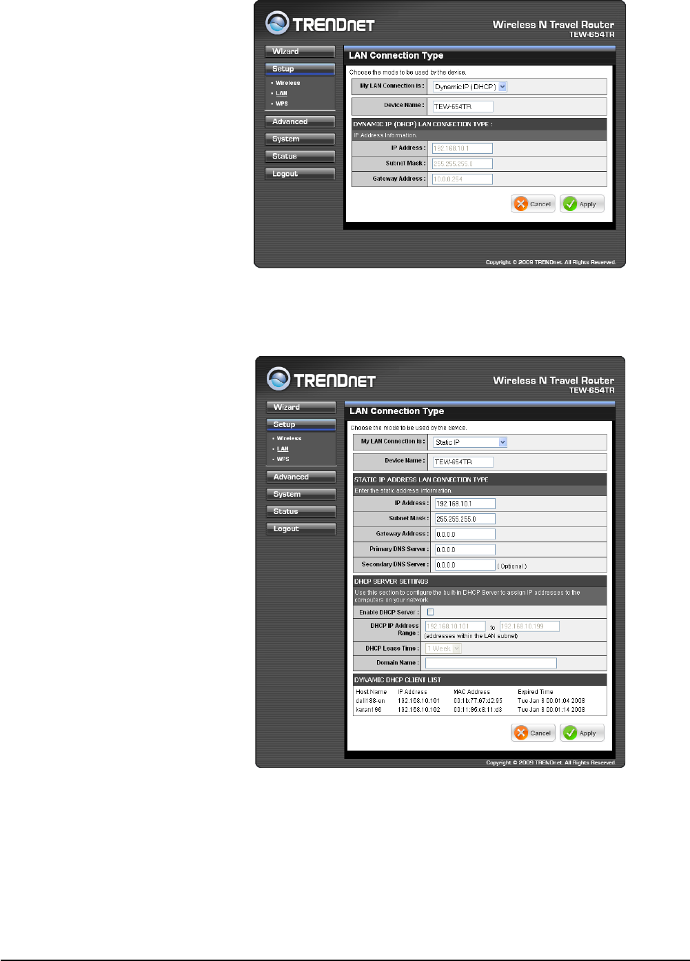
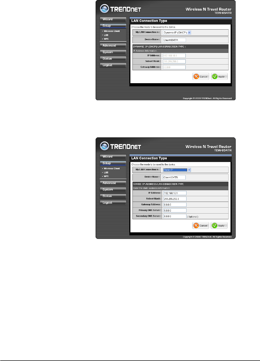
Dynamic IP (DHCP)
My LAN Connection is
Select Dynamic IP (DHCP) to
obtain the IP address information
automatically from your ISP. The
IP Address, Subnet Mask, and
Gateway Address are shown on
the page.
Device Name
Displays the default device
name.
Static IP
My LAN Connection is
Select Static IP if you are required to use a permanent IP address to connect to the
Internet. You need to manually enter the information provided by your ISP.
IP Address
Enter the IP address provided by
your ISP.
Subnet Mask
Enter the subnet mask provided
by your ISP.
Gateway Address
Enter the gateway address
provided by you ISP.
Primary / Secondary DNS
Server
Enter the DNS server addresses
provided by your ISP.
Enable DHCP Server
Check the box to use the travel
router as a DHCP server for
your network. A DHCP server
automatically assigns an IP
address to each client on your network. This function is disabled by default.
DHCP IP Address Range
Enter the starting and ending range of IP addresses that can be assigned to clients
on your network.
DHCP Lease Time
Select the length of time to “lease” the dynamic IP address from the list. The default
time is 1 Week.
Local Area Network (LAN) Settings
Wireless Travel Router22 Wireless Travel Router22
2. AP MODE
Domain Name
Enter the domain name (optional).
Dynamic DHCP Client List window
Displays the list of DHCP clients.
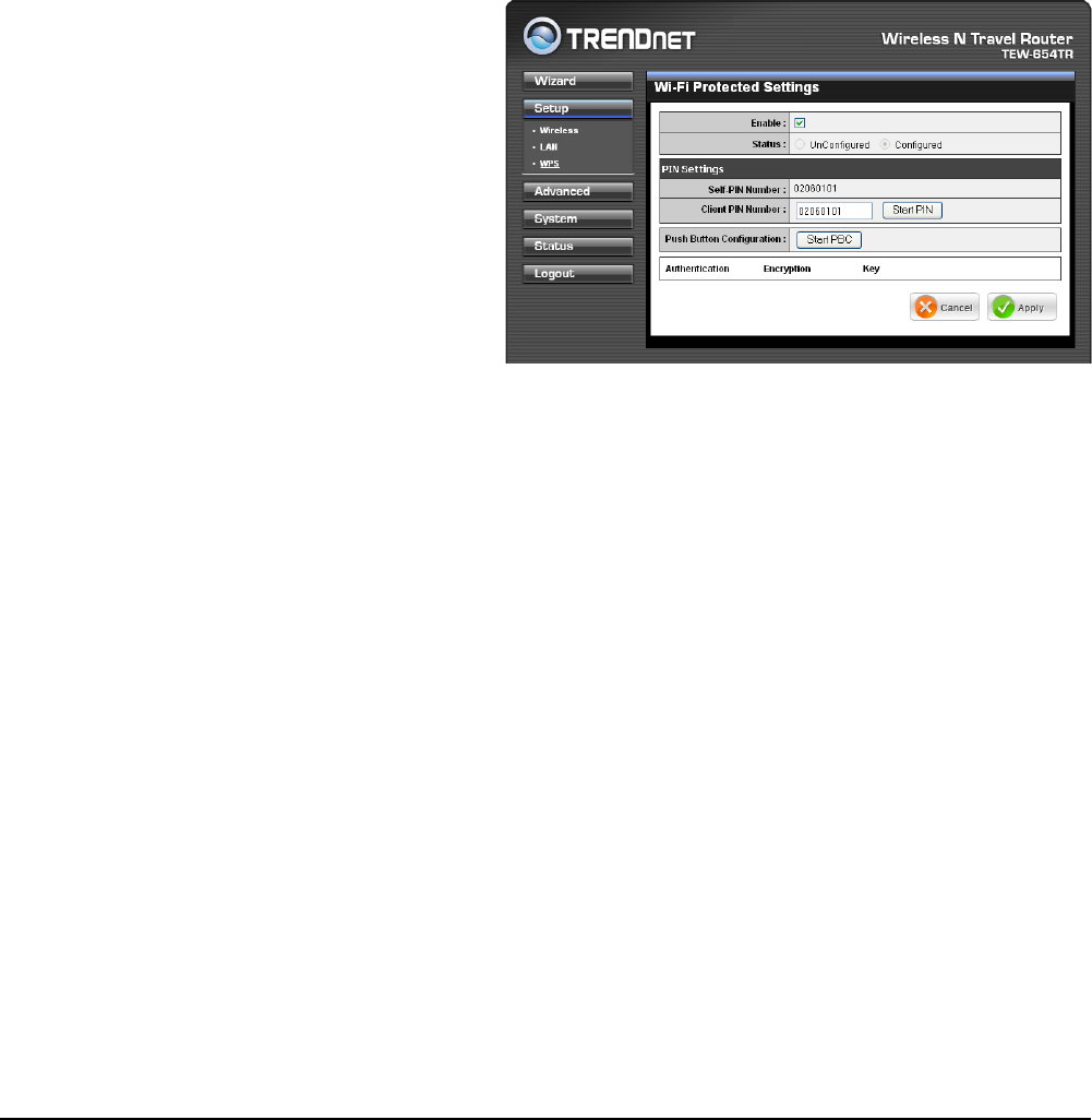
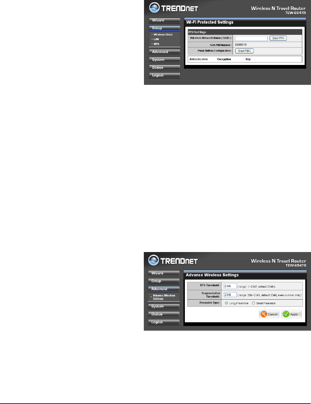
Enable
Check the box to enable WPS
function.
Status
Displays WPS status:
UnCongured or Congured.
Wi-Fi Protected Setup (WPS) Settings
Wi-Fi Protected Setup (WPS) is an optional certication program from the Wi-Fi
Alliance that is designed to ease the task of setting up and conguring security on a
wireless network.
Push Button: If the client device has a WPS button.
PIN Number: If the client device has a WPS PIN number.
Self-PIN Number
Displays the default PIN number of the travel router.
Client PIN Number
Enter the client’s PIN number. This PIN number will be used to communicate with the
travel router to connect to the network.
Start PIN
Click this button to start WPS conguration process if the client device has a WPS
PIN number.
Push Button Conguration
Click the Start PBC button to start WPS conguration process if the client device has
a WPS button.
•
•
There are 2 methods used in WPS conguration:
Once conguration is complete, click Apply to save and apply settings, or click
Cancel to cancel changes. The travel router will restart for new settings to take effect.
Once conguration is complete, click Apply to save and apply settings, or click
Cancel to cancel changes. The travel router will restart for new settings to take effect.
Wireless Travel Router 23Wireless Travel Router 23
2. AP MODE
2.2.3 Advanced
The Advanced menu congurations greatly affect the operating performance of the
travel router. This menu is intended for advanced users. It is recommended to retain
the default settings. Do not change any of congurations if you are unsure about it.
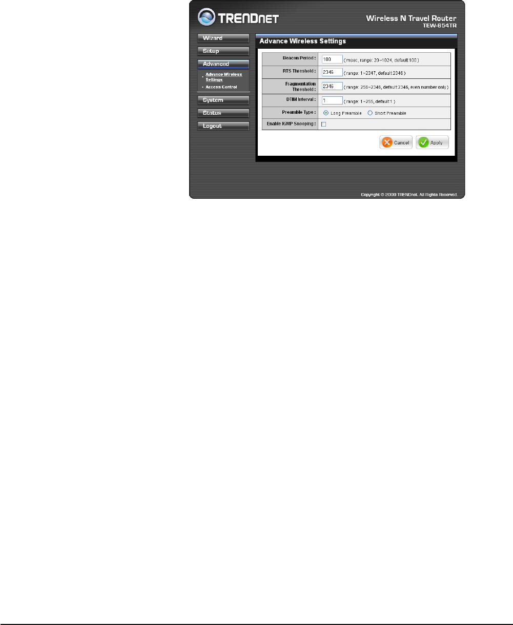
Advanced Wireless Network Settings
Beacon Period
Enter the interval period of time
for the access point to send
out beacons to synchronize the
wireless network. The default
value is 100 milliseconds.
RTS Threshold
The default and the
recommended value is
2346. Should you encounter
inconsistent data ow, only
minor adjustments should be
made.
Fragmentation Threshold
Fragmentation threshold refers to the amount of packets that will be fragmented
before transmission. The default and recommended value is 2346 bytes.
DTIM Interval
This value indicates the interval of Delivery Trafc Indication Message (DTIM).
A DTIM is a countdown eld informing clients of the next window for listening to
broadcast and multicast messages. The default value is 1.
Preamble Type
Preamble is use to limit the packets of data for transmission. When the connection is
bad, it is recommended to use the Short Preamble.
Enable IGMP Snooping
Check the box to enable Internet Group Management Protocol (IGMP) snooping.
This function restrains multicast trafc in a switched network.
Once conguration is complete, click Apply to save and apply settings, or click
Cancel to cancel changes. The travel router will restart for new settings to take effect.
Wireless Travel Router24 Wireless Travel Router24
2. AP MODE
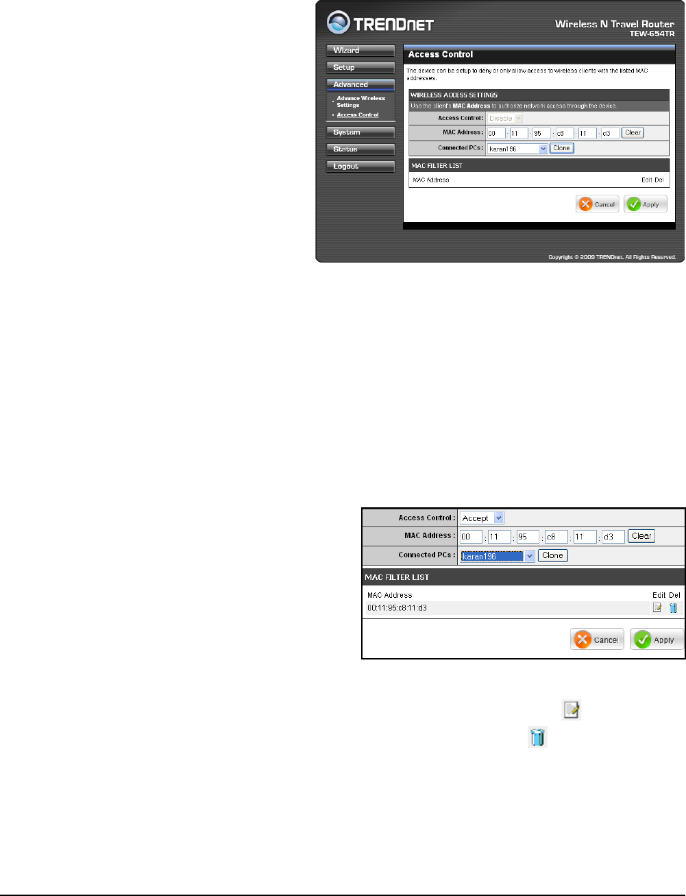
Access Control
The Access Control menu allows you deny or only allow access to certain wireless
clients by ltering their MAC addresses.
Access Control
Select the type of access from
the list:
Disable: Disable access
control.
Reject: Deny the MAC
addresses shown on the
list to access the wireless
network.
Accept: Only allow the MAC
addresses shown on the list
to access to wireless network.
MAC Address
•
•
•
1 Select the client from the Connected PCs list, then click Clone. The cloned
MAC address is displayed in the MAC Address eld.
2 Click Apply to add MAC address in the MAC Filter List. The system will
reboot.
Displays the cloned MAC address. To clear the MAC address, click Clear.
Connected PCs
Select the name of the connected client that you want to clone. Click Clone to clone
its MAC address.
To grant or block access:
3 After rebooting, select the
Access Control option:
Disable, Reject or Accept.
4 Click Apply to save setting. The
system will reboot for changes
to take effect.
5 To add more MAC addresses,
repeat steps 1-4.
To edit the access control of a MAC address, click its corresponding icon.
To delete the MAC address from the list, click its corresponding icon.

Wireless Travel Router 25Wireless Travel Router 25
2. AP MODE
2.2.4 System
The System menu provides password conguration, backup and restore settings,
rmware update and date and time settings.
Admin
The Admin submenu allows you to change the default user name and password
which are use to login.
New User Name
Enter the new user name here.
New / Conrm Password
Enter the password.
Click Apply to save and apply settings, or click Cancel to cancel changes. The travel
router will restart for new settings to take effect.
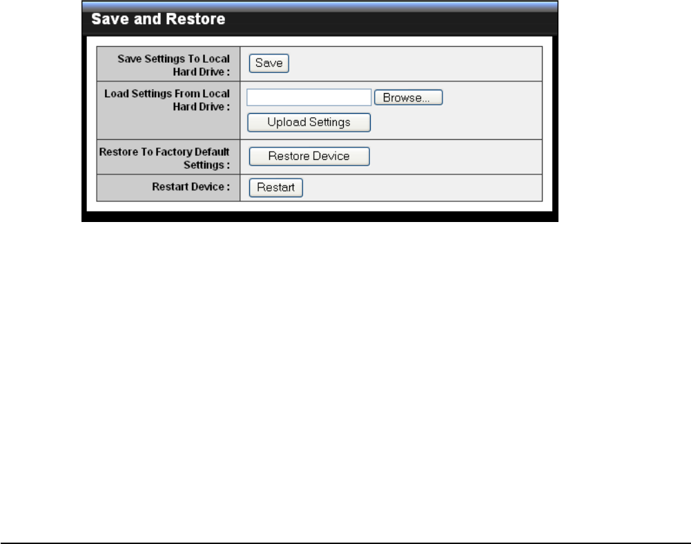
Settings
The Settings submenu provides backup and restore setting functions.
Save Settings to Local Hard Drive
Use this function to save the current conguration settings to your local hard drive.
Click Save, then select the folder where you want to save the le.
Load Settings From Local Hard Drive
Use this function to retrieve saved conguration settings from the local hard drive.
1 Click Browse to locate the le.
2 Click Upload Settings to transfer and apply the settings to the travel router.
Restore to Factory Default Settings
Click Restore Device to restore all congurations to the factory default settings. All
changes in conguration will be deleted.
Restart Device
Click Restart to reboot the travel router.

Wireless Travel Router26 Wireless Travel Router26
2. AP MODE
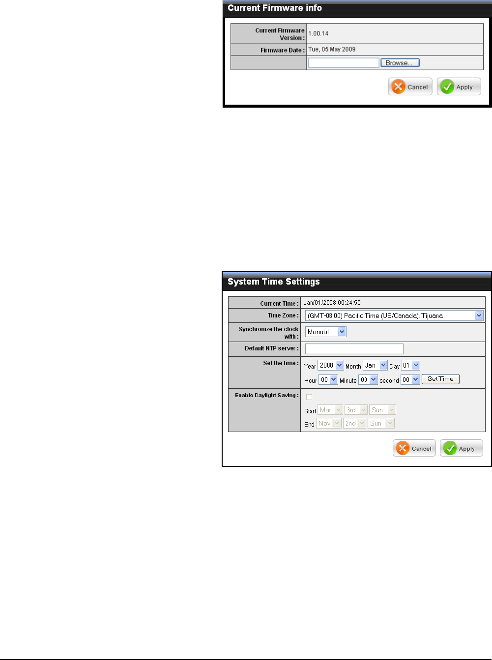
Firmware
The Firmware submenu allows you to upgrade the rmware to the latest version.
Current Firmware Version
Displays the current rmware
version.
Firmware Date
Displays the date when the
rmware was last updated.
Time
The Time submenu allows you to manually adjust the system time settings or
synchronize it with a server.
Current Time
Displays the current date and
time settings.
Time Zone
Select the time zone in your
area.
Synchronize the clock with
Select:
Manual: To manually adjust
the date and time.
Automatic: To synchronize
date and time with the server.
•
•
Default NTP Server
Enter the NTP server address to synchronize the date and time with.
Set the Time
Use this option to manually set the date and time. This option is only available when
Synchronize the clock with is set to Automatic.
Enable Daylight Saving
Check the box to enable daylight saving time. Use the Start and End eld boxes to
specify the starting and ending dates.
Click Apply to save and apply settings, or click Cancel to cancel changes. The travel
router will restart for new settings to take effect.
1 Download the latest rmware from the manufacturer’s website, and save it
to a disk.
2 Click Browse to locate the le.
3 Click Apply to start rmware update. The system will reboot to complete
update.
Wireless Travel Router 27Wireless Travel Router 27
2. AP MODE
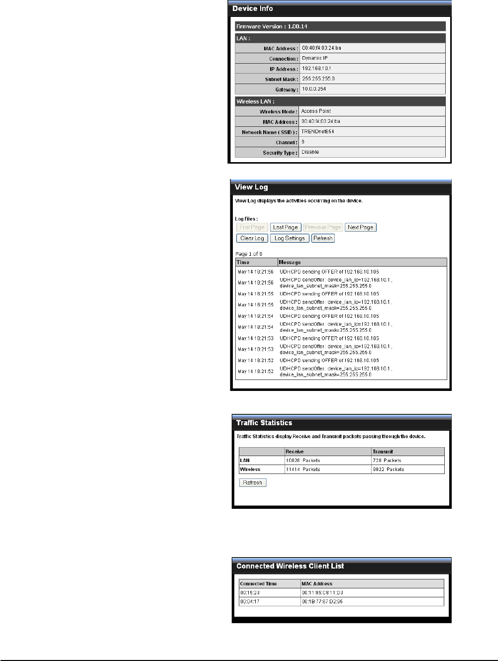
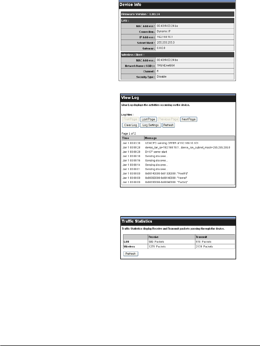
2.2.5 Status
The Status menu displays device, logs, trafc, and connection information.
Logs
This page displays the recorded events
that occur within the wireless network.
Click the following buttons to view the
First Page, Last Page, Previous Page,
and Next Page.
To delete log data, click Clear Log.
To change log settings, click Log
Settings.
To refresh list, click Refresh.
Statistics
This page displays the trafc statistics
of received and transmitted packets that
passed through the travel router.
Click Refresh to refresh table.
Wireless
This page displays the information of
connected wireless clients such as
the time of connection and their MAC
addresses.
Device Info
This page displays the Firmware
Version, LAN and Wireless LAN
information.

Wireless Travel Router28
3
Client Mode
Before You Begin
With Client mode, you can transform Ethernet-enabled devices to have wireless
function using the travel router.
Checklist
A valid network or Internet connection.
A DSL / cable modem provided by the ISP as part of the broadband connection
installation.
A broadband router that connects to the DSL / cable modem for internet
connection sharing.
√
√
√
You need to connect...
Connect the travel router to your router or network that has a DHCP server. The
travel router will obtain an IP address from the network automatically.
Connect the LAN port of the travel router to the LAN port on your network then
plug in the power adapter.
Use wireless adapters to connect to the ravel router (default SSID TRENDnet654).
•
•
•
Wireless Travel Router 29Wireless Travel Router 29
3. CLIENT MODE
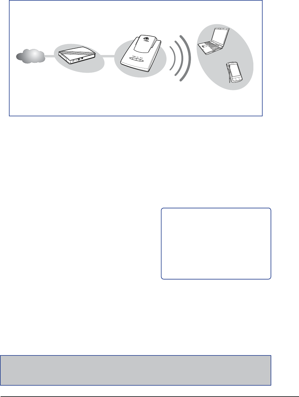
3.1 Installation
Internet
ADSL /
Cable Modem
WLAN AP /
Router
Wireless Station
Printer
Game Console
Network Diagram
The following LED
indicators should be lit...
Power LED (solid)
LAN LED (solid)
WLAN LED (ashing green)
√
√
√
1 Adjust the switch to Client mode.
2 Connect one end of the RJ-45 cable to the travel router and the other end to
the LAN port of the computer or other device.
3 Turn on or plug in the DSL / cable modem and the wireless router.
4 Connect the power adapter to the travel router and plug to an outlet or power
strip. Wait for the travel router to boot.
5 Check the LED indicators to verify connection.
3.1.1 Infrastructure Mode
With infrastructure mode, all clients connect to a central access point (AP), all data
pass through this access point.

Wireless Travel Router30 Wireless Travel Router30
3. CLIENT MODE
3.1.2 Ad-Hoc Mode
Ad-Hoc is a client setting that provides independent peer-to-peer connectivity in a
wireless LAN. With this mode, devices communicate directly with each other. A good
example is the communication between two game consoles. See diagram below.
1 Adjust the switch to Client mode.
2 Connect one end of the RJ-45 cable to the travel router and the other end to
the game console or other devices.
3 Connect the power adapter to the travel router and plug to an outlet or power
strip. Wait for the travel router to boot.
Network Diagram
Game Console
Game Console
The following LED
indicators should be lit...
Power LED (solid)
LAN LED (solid)
WLAN LED (ashing green)
√
√
√
Wireless Travel Router 31Wireless Travel Router 31
3. CLIENT MODE
3.2 Web-Based Conguration
After making all the required connections, congure the travel router using the web-
based conguration utility.
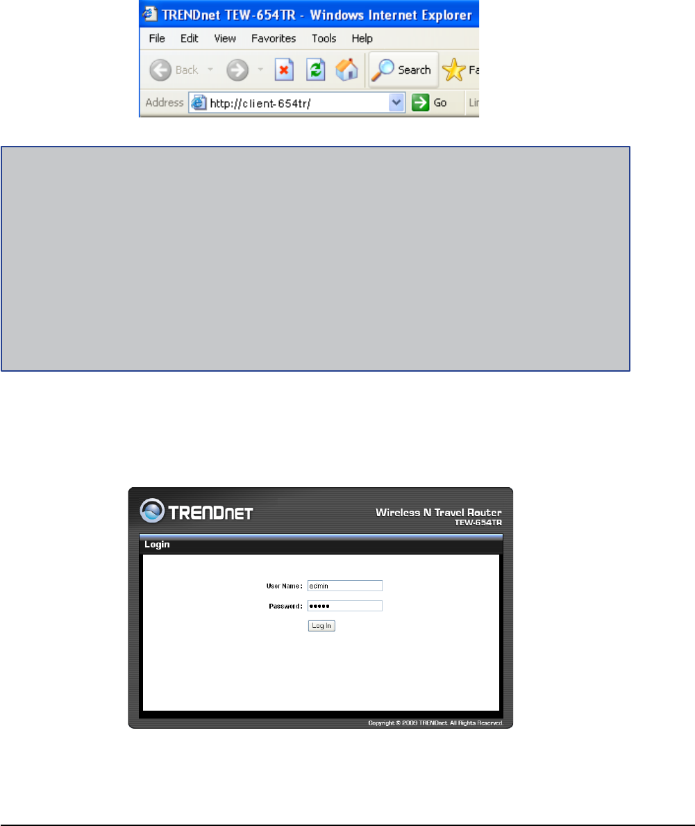
How to Access the Conguration Utility
1 Open a web-browser and enter default address: http://client-654tr/.
2 Enter the default User Name and Password: admin.
Notes:
You can also access the web-based conguration by any of the following ways:
1. If your LAN connection uses DHCP, the travel router can obtain an IP address from the DHCP
server. You can either enter that IP address or the default address http://client-654tr/ on the
browser’s address eld to open the web-based conguration utility.
2. If your LAN connection uses Static IP, You can either enter http://client-654tr/ or that static IP
address on the browser’s address eld. The default IP address is 192.168.10.1.
If you cannot access the conguration utility:
Disable the Internet security software on the computer. The rewall may block access to the
conguration page. Check the software rewall documentation for help.
•
Wireless Travel Router32 Wireless Travel Router32
3. CLIENT MODE
3.2.1 Wizard
Click the Wizard button to congure the travel router using the setup wizard.
1 Click Next to continue.
2 Create a new Password, then click
Next to continue.
3 Create a new Wireless Network Name
and select the Channel (6 by default).
Click Next to continue.
After login, the Status > Device Info page is displayed.
Note:
For novice users, it is recommended to use the Setup Wizard to congure the travel router.
To access a page, click the buttons on the right.
To logout, click Logout.
Wireless Travel Router 33Wireless Travel Router 33
3. CLIENT MODE
5 The wireless security setting is displayed.
Take note of the information then click
Save.
The information shown varies depending
on the selected security level.
6 Click Restart to reboot the access point
and the device.
If you select Better...
Enter the Passphrase, then click Next to
continue.
Skip to step 5.
If you select Good...
Select the Key Format and Key Length.
Enter the WEP Key, then click Next to
continue.
4 Select the type of security, then click
Next to continue.
If you select None, skip to step 5.
If you select Best...
Enter the Passphrase, then click Next to
continue.
Skip to step 5.
Note:
The Passphrase must be 8-63 ASCII characters or 64 hexadecimal characters.
Wireless Travel Router34 Wireless Travel Router34
3. CLIENT MODE
3.2.2 Setup
The Setup menu allows you to congure basic router settings. Click the Setup button
then the submenu to view page.
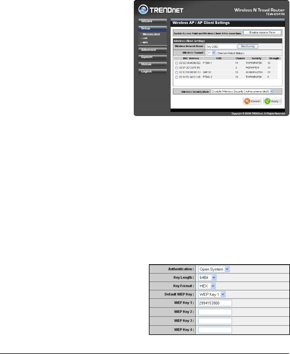
Wireless AP/ AP Client Settings
Enable Access Point
Click this button to access
Wireless Network Settings page.
See page 36.
Site Survey
Click this button to scan for
available networks. Available
networks are listed on the table.
To select a network, click on the
network’s radio button.
Wireless Network Name
Displays the name of the
selected wireless network, also
called Service Set Identier (SSID).
Wireless Channel
Displays the wireless channel of the selected network.
Wireless Security Mode
Displays the security mode of the selected network.
Disable Wireless Security: No wireless security is set.
Enable WEP Wireless Security (basic)
Enable WPA Wireless Security (enhanced)
Enable WPA-2 Wireless Security (enhanced)
The required settings vary depending on the wireless security mode.
•
•
•
•
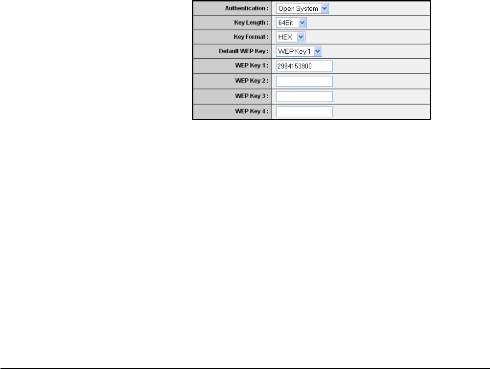
WEP
WEP (Wired Equivalent Privacy) is the basic encryption method. With WEP
encryption, all wireless clients must enter the same key to connect to the access
point.
Authentication
Select the type of authentication:
Open system: Allows public
access to the travel router via
wireless communications.
Shared Key: Requires users
to enter the same WEP key
to exchange data with other
wireless devices.
•
•
Wireless Travel Router 35Wireless Travel Router 35
3. CLIENT MODE
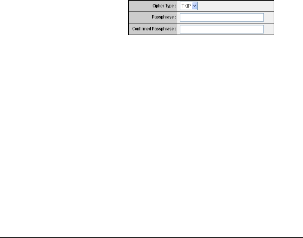
WPA / WPA-2
Cipher Type
Select the encryption method:
TKIP: Temporal Key Integrity
Protocol.
AES: Advanced Encyption
Standard.
•
•
Passphrase
Enter the required passphrase to connect to the selected network. The
passphrase must be 64 hexadecimal or 8-63 ASCII characters.
Conrm Passphrase
Re-enter passphrase.
Click Apply to save and apply settings, or click Cancel to cancel changes. The travel
router will restart for new settings to take effect.
Auto: Select Auto if you are unsure.
Key Length
Select the key length or the level of encryption:
64Bit: Select to enter 10 hexadecimal characters with any combination of 0-9 or
A-F
128Bit: Select to enter 26 hexadecimal characters with any combination of 0-9
or A-F
Key Format
Select the key format:
ASCII: Select to enter ASCII characters.
HEX: Select to enter hexadecimal characters.
Default WEP Key
Select which WEP Key is used as the default key from the list.
WEP KEY 1-4
Manually enter a set of WEP key for each box. Select the default WEP key from
the Default WEP Key list.
•
•
•
•
•

Wireless Travel Router36 Wireless Travel Router36
3. CLIENT MODE
client at the same time.
Enable Access Point
Check the box to enable access point
function. Uncheck to disable it.
Wireless Network Name
The name of your wireless network,
also called Service Set Identier
(SSID). Enter up to 32 characters.
Enable Auto Channel Scan
Auto channel scan selects the channel with the least amount of interference. Check
to enable auto channel scan.
Wireless Channel
Manually select the channel from the list. By default, the channel is set to 6. If Enable
Auto Channel Scan is checked, this box is grayed out.
802.11 Mode
Limit the type of wireless clients to allow connection with. Select any of the following
modes if your clients are:
2.4Ghz 802.11b/g mixed mode: a mix of 802.11b and 11g wireless devices.
2.4Ghz 802.11b/g/n mixed mode: a mix of 802.11b, 11g, 11n wireless devices.
2.4Ghz 802.11n only mode: all 802.11n wireless devices.
Channel Width
Select the appropriate channel width:
20 MHz (Default): Select if your wireless clients are not 802.11n.
Auto 20/40 MHz: Select if your wireless clients are a mix of 802.11b, 11g, 11n
wireless clients. If you are not sure which wireless clients you are using, select
Auto.
Enable Hidden Wireless
Check to hide the SSID of your wireless network to be broadcasted when wireless
clients scan for wireless networks. To display the router’s SSID, keep the box
unchecked (default).
WMM Enable
Wi-Fi Multimedia (WMM) improves the quality of video and voice applications
transmitted over a wireless network. This function is commonly used with multimedia
applications such as a game console. Check the box to enable WMM.
Enable WISP Mode
Check the box to enable Wireless Internet Service Provider (WISP). WISP is
commonly used in wireless hotspots, such as coffee shops, airports. etc. When the
travel router is connected to a wireless hotspot, it connects with a WISP account
•
•
•
•
•
Wireless Network Settings
Use this page to enable and setup the travel router as an access point and wireless
Wireless Travel Router 37Wireless Travel Router 37
3. CLIENT MODE
and is assigned a public IP address. This account and public IP address are then
shared and used by all connected clients. The connected clients receive private IP
addresses from the travel router. If WISP is disabled, the travel router does not share
the WISP account, instead, connected clients must connect to the wireless network
directly.
Wireless Security Mode
Select the security level for your wireless network. Select the wireless security mode
from the list:
Disable Wireless Security: (Default) Select if you do not want to use any wireless
security.
Enable WEP Wireless Security (basic)
Enable WPA Wireless Security (enhanced)
Enable WPA-2 Wireless Security (enhanced)
Enable WPA-Auto Wireless Security (enhanced): Select if you are unsure which
WPA wireless security to use.
The required settings vary depending on the selected mode.
WEP
WEP (Wired Equivalent Privacy) is the basic encryption method. With WEP
encryption, all wireless clients must enter the same key to connect to the access
point.
•
•
•
•
•
Authentication
Select the type of authentication:
Open system: Allows public
access to the travel router via
wireless communications.
Shared Key: Requires users
to enter the same WEP key
to exchange data with other
wireless devices.
Auto: Select Auto if you are
•
•
•
unsure which authentication suits best for your wireless clients.
Key Length
Select the key length or the level of encryption:
64Bit: Select to enter 10 hexadecimal characters with any combination of 0-9 or
A-F
128Bit: Select to enter 26 hexadecimal characters with any combination of 0-9
or A-F
Key Format
Select the key format:
ASCII: Select to enter ASCII characters.
HEX: Select to enter hexadecimal characters.
Default WEP Key
The travel router supports up to 4 sets of WEP keys. Select which WEP Key is
used as the default key from the list.
•
•
•
•
Wireless Travel Router38 Wireless Travel Router38
3. CLIENT MODE
WEP KEY 1-4
Manually enter a set of WEP key for each box. Select the default WEP key from the
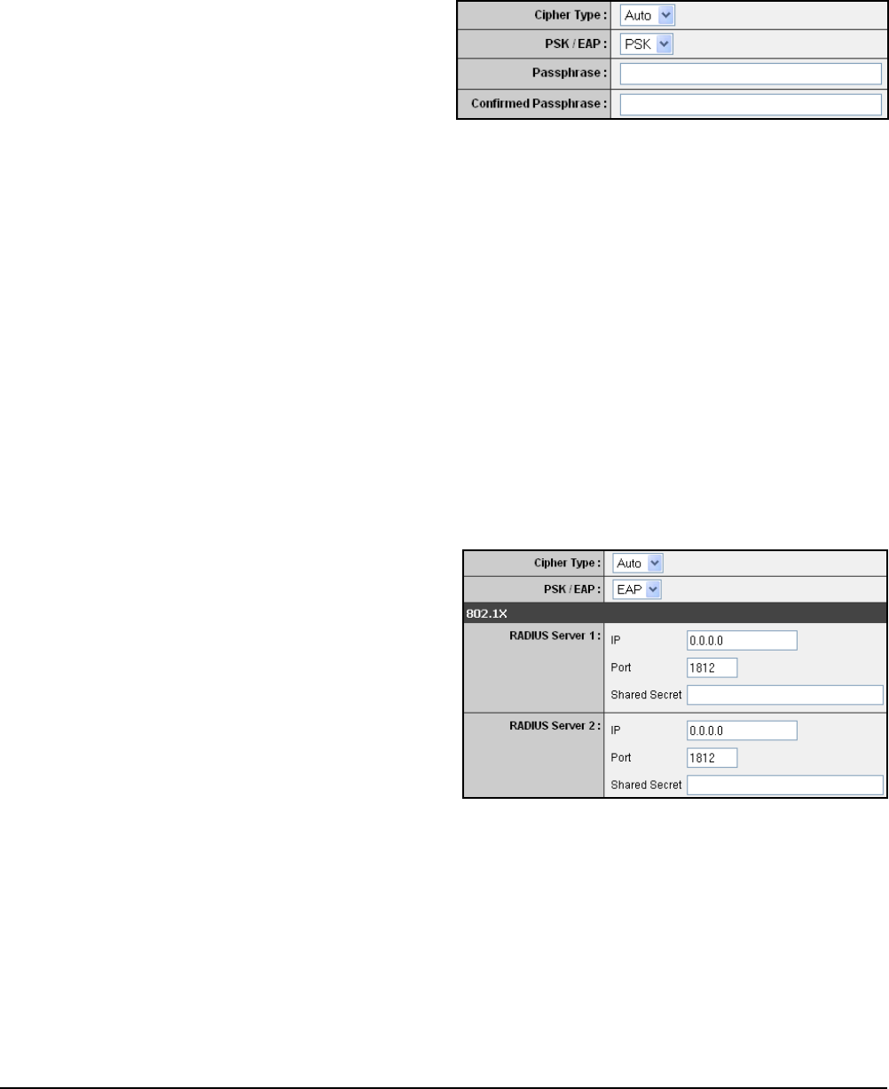
Default WEP Key list.WPA / WPA-2 / WPA-Auto
WPA (Wi-Fi Protected Access) uses high grade encryption and authentication
which is designed to improve WEP encryption. WPA / WPA-2 / WPA-Auto uses a
passphrase to authenticate wireless connections.
Cipher Type
Select the encryption method:
TKIP: Temporal Key Integrity
Protocol.
AES: Advanced Encyption
Standard.
•
•
Auto: Select Auto if you are unsure which method is suitable for your wireless
clients.
PSK/EAP
Select the authentication method:
PSK: Select to use a passphrase for authentication.
•
•
EAP: Select to use Extensible Authentication Protocol (EAP). This should only
be used when a Radius server is connected to the travel router. You can have
up to 2 Radius server settings.
•
IP
Enter the IP address of the
Radius server.
Port
Enter the port number of the
Radius server. The default
value is 1812.
Shared Secret
Enter the secret key shared
between the travel router and
the Radius server.
Once conguration is complete, click Apply to save and apply settings, or click
Cancel to cancel changes. The travel router will restart for new settings to take effect.
Passphrase
Create a passphrase. The passphrase must be 64 hexadecimal or 8-63
ASCII characters.
Conrm Passphrase
Re-enter passphrase.
Wireless Travel Router 39Wireless Travel Router 39
3. CLIENT MODE
Dynamic IP (DHCP)
My LAN Connection is
Select Dynamic IP (DHCP) to
obtain the IP Address information
automatically from your ISP. The
IP Address, Subnet Mask, and
Gateway Address are shown on
the page.
Device Name
Displays the default device
name.
Static IP
My LAN Connection is
Select Static IP if you are required to use a permanent IP Address to connect to the
Internet. You need to manually enter the information provided by your ISP.
IP Address
Enter the IP address provided by
your ISP.
Subnet Mask
Enter the subnet mask provided
by your ISP.
Gateway Address
Enter the gateway address
provided by you ISP.
Primary / Secondary DNS
Server
Enter the DNS server addresses
provided by your ISP.
Local Area Network (LAN) Settings
Once conguration is complete, click Apply to save and apply settings, or click
Cancel to cancel changes. The travel router will restart for new settings to take effect.
Wireless Travel Router40 Wireless Travel Router40
3. CLIENT MODE
Wireless Network Name (SSID)
The name of the wireless
network you want to PIN, also
called Service Set Identier
(SSID).
Start PIN
Click this button to start WPS
conguration process if the client
device has a WPS PIN number.
Wi-Fi Protected Setup (WPS) Settings
Wi-Fi Protected Setup (WPS) is an optional certication program from the Wi-Fi
Alliance that is designed to ease the task of setting up and conguring security on a
wireless network.
Self-PIN Number
Displays the default PIN number of the travel router.
Push Button Conguration
Click the Start PBC button to start WPS conguration process if the client device has
a WPS button.
Once conguration is complete, click Apply to save and apply settings, or click
Cancel to cancel changes. The travel router will restart for new settings to take effect.
3.2.3 Advanced
The Advanced menu congurations greatly affect the operating performance of the
travel router. This menu is intended for advanced users. It is recommended to retain
the default settings. Do not change any of congurations if you are unsure about it.
Advanced Wireless Network Settings
RTS Threshold
The default and the
recommended value is
2346. Should you encounter
inconsistent data ow, only
minor adjustments should be
made.
Fragmentation Threshold
Fragmentation threshold refers to the amount of packets that will be fragmented
before transmission. The default and recommended value is 2346 bytes.
Preamble Type
Preamble is use to limit the packets of data for transmission. When the connection is
bad, it is recommended to use the Short Preamble.
Wireless Travel Router 41Wireless Travel Router 41
3. CLIENT MODE
3.2.4 System
The System menu provides password conguration, backup and restore settings,
rmware update and date and time settings.
Admin
The Admin submenu allows you to change the default user name and password
which are use to login.
New User Name
Enter the new user name here.
New / Conrm Password
Enter the password.
Click Apply to save and apply settings, or click Cancel to cancel changes. The travel
router will restart for new settings to take effect.
Settings
The Settings submenu provides backup and restore setting functions.
Save Settings to Local Hard Drive
Use this function to save the current conguration settings to your local hard drive.
Click Save, then select the folder where you want to save the le.
Load Settings From Local Hard Drive
Use this function to retrieve saved conguration settings from the local hard drive.
1 Click Browse to locate the le.
2 Click Upload Settings to transfer and apply the settings to the travel router.
Restore to Factory Default Settings
Click Restore Device to restore all congurations to the factory default settings. All
changes in conguration will be deleted.
Restart Device
Click Restart to reboot the travel router.
Wireless Travel Router42 Wireless Travel Router42
3. CLIENT MODE
Firmware
The Firmware submenu allows you to upgrade the rmware to the latest version.
Current Firmware Version
Displays the current rmware
version.
Firmware Date
Displays the date when the
rmware was last updated.
Time
The Time submenu allows you to manually adjust the system time settings or
synchronize it with a server.
Current Time
Displays the current date and
time settings.
Time Zone
Select the time zone in your
area.
Synchronize the clock with
Select:
Manual: To manually adjust
the date and time.
Automatic: To synchronize
date and time with the server.
•
•
Default NTP Server
Enter the NTP server address to synchronize the date and time with.
Set the Time
Use this option to manually set the date and time. This option is only available when
Synchronize the clock with is set to Automatic.
Enable Daylight Saving
Check the box to enable daylight saving time. Use the Start and End eld boxes to
specify the starting and ending dates.
Click Apply to save and apply settings, or click Cancel to cancel changes. The travel
router will restart for new settings to take effect.
1 Download the latest rmware from the manufacturer’s website, and save it
to a disk.
2 Click Browse to locate the le.
3 Click Apply to start rmware update. The system will reboot to complete
update.
Wireless Travel Router 43Wireless Travel Router 43
3. CLIENT MODE
3.2.5 Status
The Status menu displays device, logs, trafc, and connection information.
Logs
This page displays the recorded events
that occur within the wireless network.
Click the following buttons to view the
First Page, Last Page, Previous Page,
and Next Page.
To delete log data, click Clear Log.
To change log settings, click Log
Settings.
To refresh list, click Refresh.
Statistics
This page displays the trafc statistics
of received and transmitted packets that
passed through the travel router.
Click Refresh to refresh table.
Device Info
This page displays the Firmware
Version, LAN and Wireless Client
information.

Wireless Travel Router44
4
Router Mode
Before You Begin
With Router mode, you can connect and share Internet connections, les, printers,
etc. between computers on the network.
Note:
Although you can connect the DSL or cable modem directly to your computer’s network card, it is
recommend to use a broadband router as an intermediary device to delegate the handling of the
Internet connection and to easily congure and share the Internet connection with other computers
on a home network.
Checklist
A broadband Internet connection.
A DSL / cable modem provided by the ISP as part of the broadband connection
installation.
A broadband router that connects to the DSL / cable modem for internet
connection sharing.
√
√
√
You need to connect...
Connect the DSL / cable modem to the WAN port or Internet port of the broadband
router using an RJ-45 Ethernet cable.
If you are currently connected to a network, disable that network connection before
you connect and congure the travel router.
Congure your computer’s Internet protocol (TCP/IP) settings. See “1.6.1
Conguring Connections”.
•
•
•
Wireless Travel Router 45Wireless Travel Router 45
4. ROUTER MODE
4.1 Installation
Internet
ADSL /
Cable Modem
Wireless Station
Mobile PDA
Network Diagram
The following LED
indicators should be lit...
Power LED (solid)
LAN LED (solid)
WLAN LED (ashing green)
√
√
√
1 Adjust the switch to Router mode.
2 Connect one end of the RJ-45 Ethernet cable to the travel router and the other
end to the broadband router.
3 Turn on or plug in the DSL / cable modem and the broadband router.
4 Connect the power adapter to the travel router and plug to an outlet or power
strip. Wait for the travel router to boot.
5 Check the LED indicators to verify
connection.
6 Enable the wireless function of the
wireless clients or devices.
Note:
Make sure you remove the power source from the travel router rst before adjusting the mode
switch.