TRENDNET TEW676APBO HIGH POWER WIRELESS OUTDOOR ACCESS POINT User Manual
TRENDNET, Inc. HIGH POWER WIRELESS OUTDOOR ACCESS POINT
UserManual.wiki
>
TRENDNET
>
TEW676APBO User Manual
>
Users Manual 2
Contents
1.
Users Manual 1
2.
Users Manual 2
Users Manual 2
Navigation menu
Upload a User Manual
Namespaces
Wiki Guide
HTML
PDF
Info
Views
User Manual
Discussion / Help
Navigation

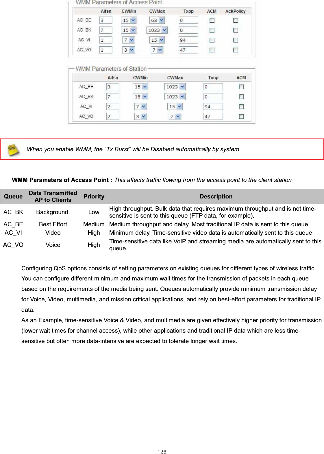


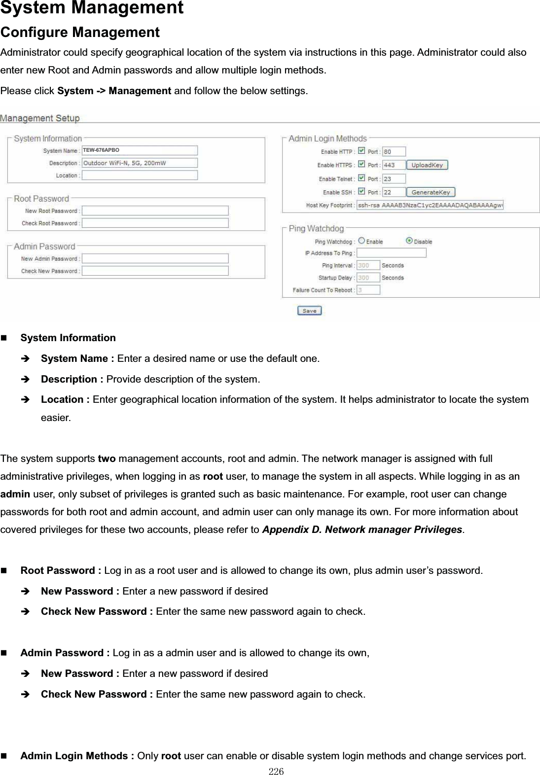

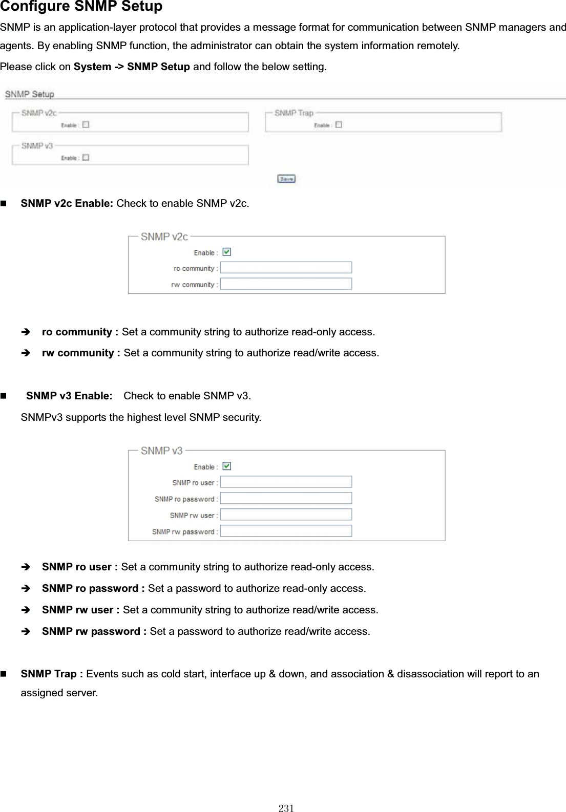

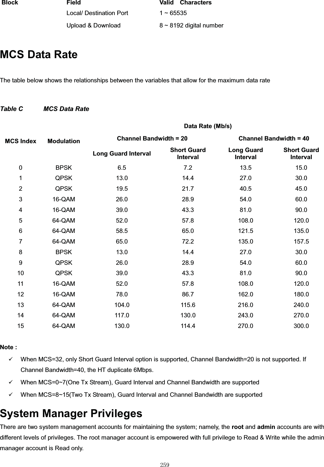
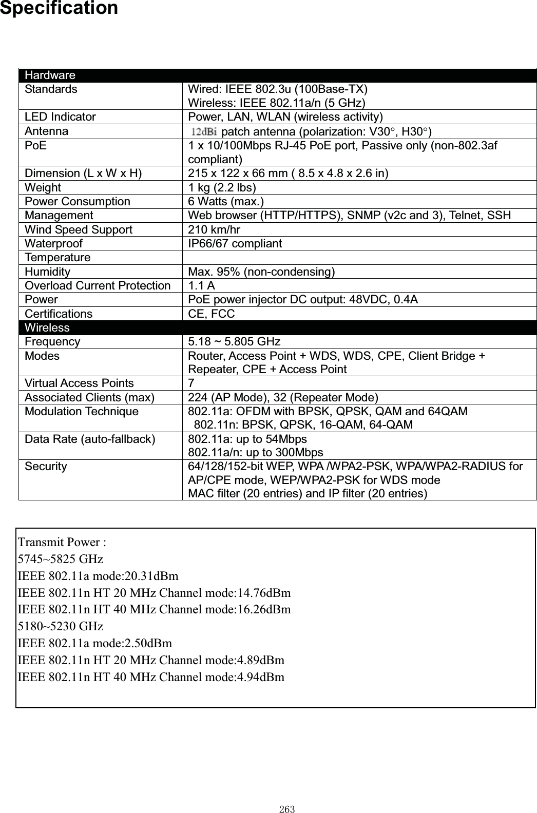
![㻞㻡㻢WEB GUI Valid Characters Table B WEB GUI Valid CharactersBlock Field Valid CharactersLAN IP Address IP Format; 1-254IP Netmask 128.0.0.0 ~ 255.255.255.252IP GatewayIP Format; 1-254Primary DNSIP Format; 1-254Secondary DNSIP Format; 1-254Hostname Length : 320-9, A-Z, a-z~ ! @ # $ % ^ * ( ) _ + - { } | : < > ? [ ] / ; ` , . =WAN Manual MAC Address 12 HEX charsIP Address IP Format; 1-254IP Netmask 128.0.0.0 ~ 255.255.255.252IP GatewayIP Format; 1-254Hostname Length : 320-9, A-Z, a-z~ ! @ # $ % ^ * ( ) _ + - { } | : < > ? [ ] / ; ` , . =User name Length : 320-9, A-Z, a-z~ ! @ # $ % ^ * ( ) _ + - { } | : < > ? [ ] / ; ` , . =PasswordMTU 576 ~ 1492 for PPPoE; 1400 ~ 1460 for PPTPIdle Time 0 ~ 60 minutesPrimary DNSIP Format; 1-254Secondary DNSIP Format; 1-254DDNS Hostname Length : 320-9, A-Z, a-z@-_ .User Name Length : 32](https://usermanual.wiki/TRENDNET/TEW676APBO.Users-Manual-2/User-Guide-1543773-Page-133.png)
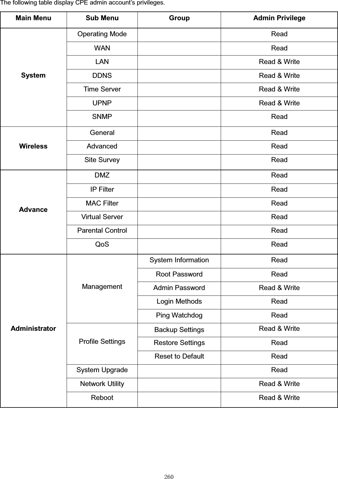
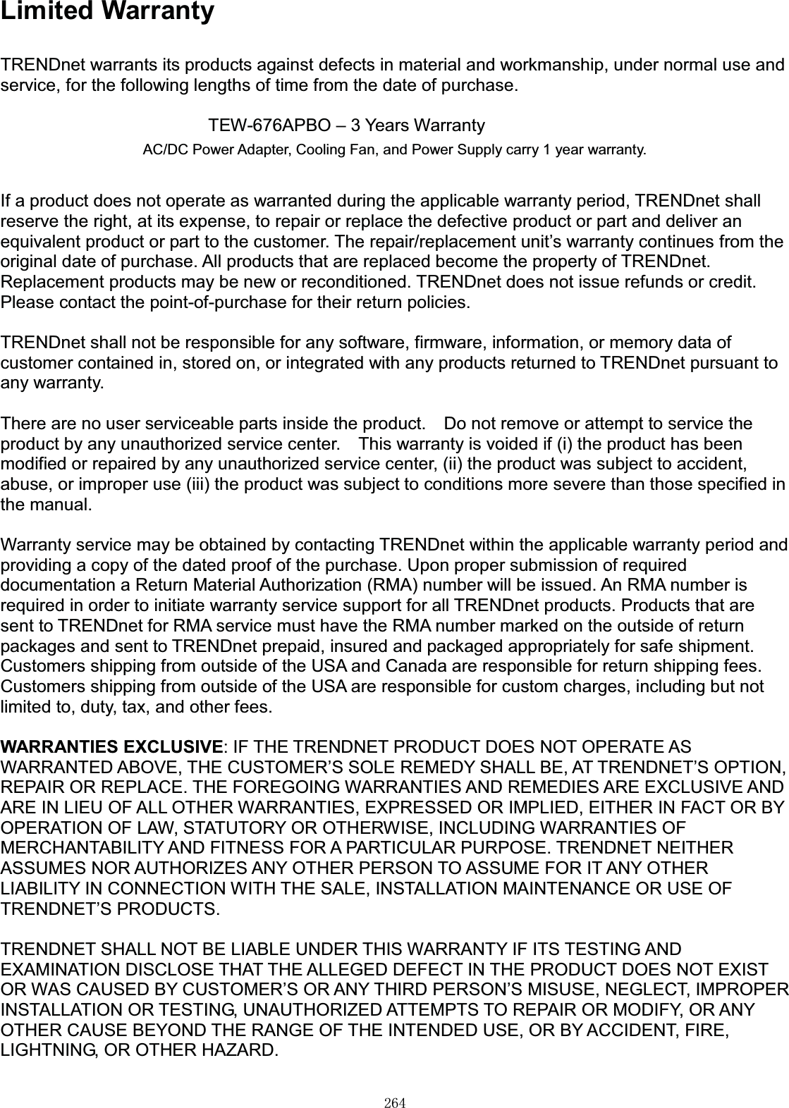
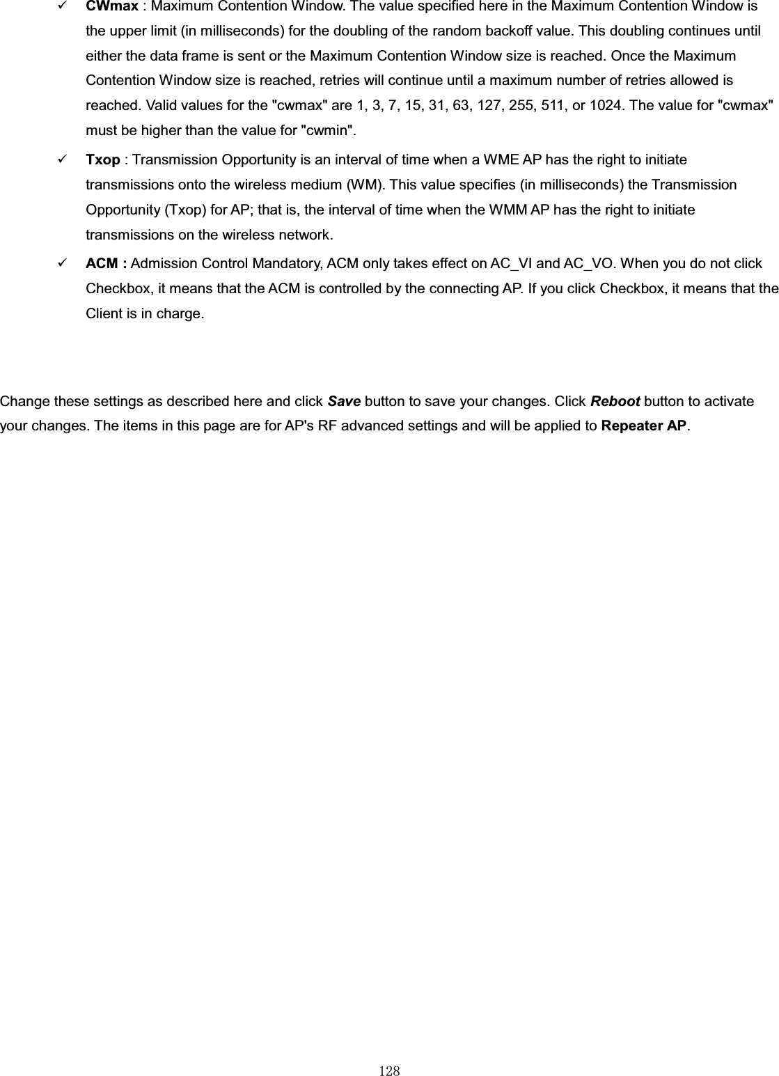
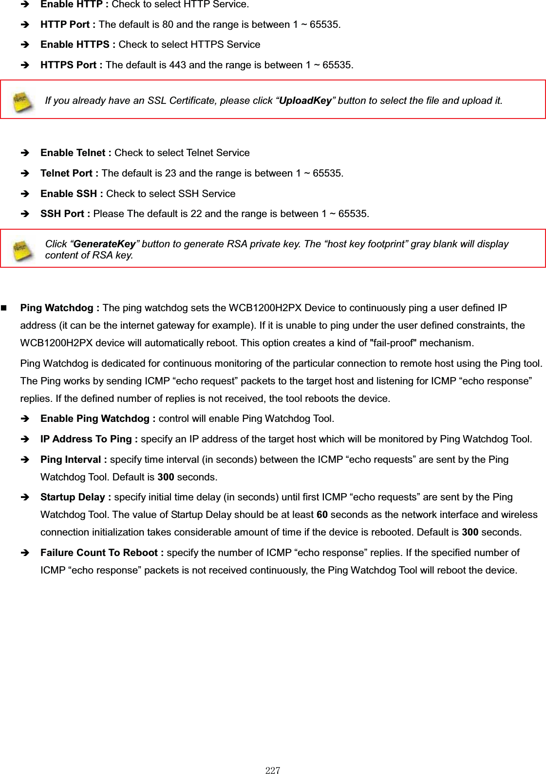
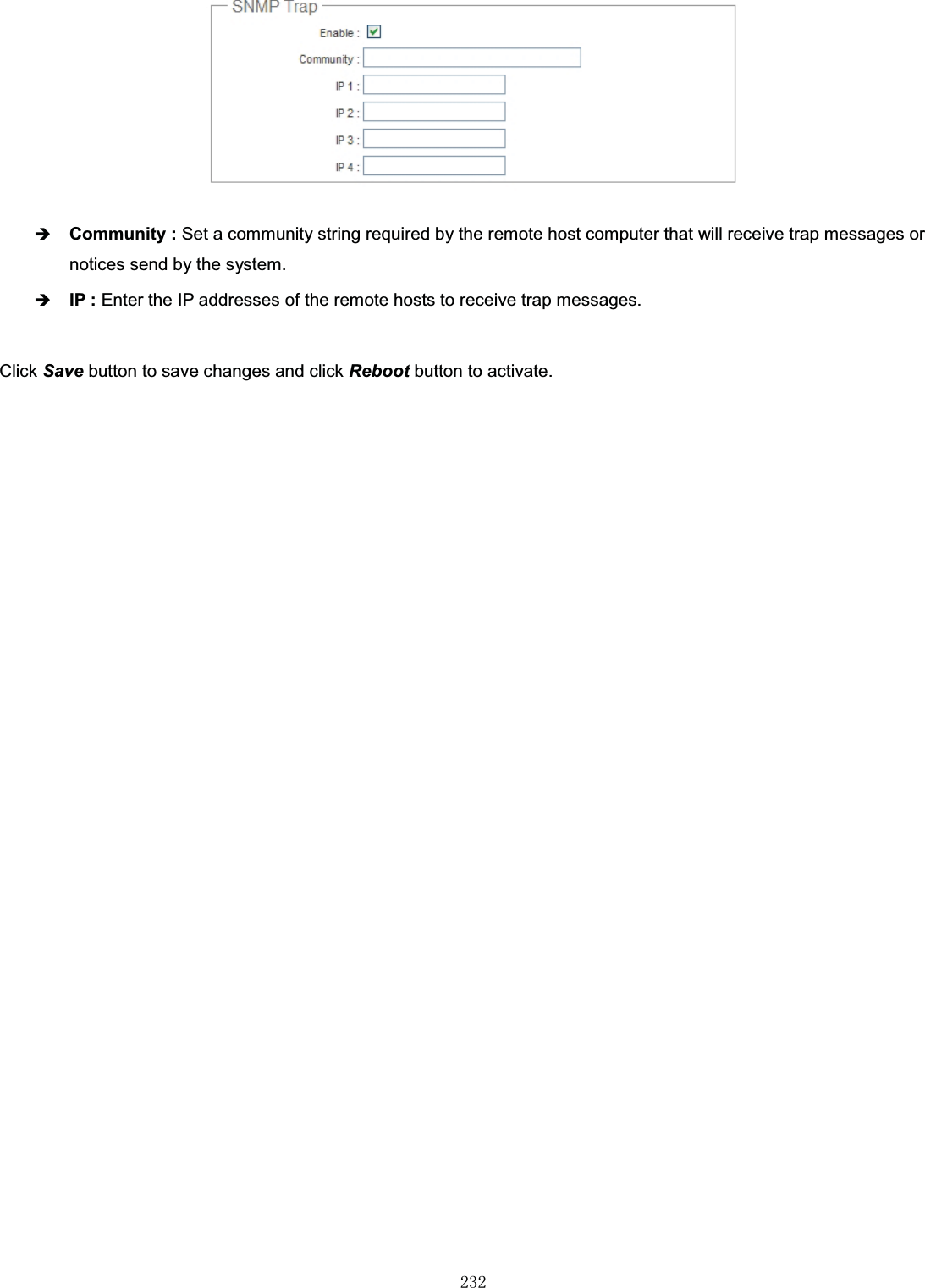
![㻞㻡㻣Password 0-9, A-Z, a-z~!@#$%^*() + {}|:<>?[]/;`=DHCP Server Start IP IP Format; 1-254End IP IP Format; 1-254DNS1 IP IP Format; 1-254DNS2 IP IP Format; 1-254WINS IP IP Format; 1-254Domain Length : 320-9, A-Z, a-z~ ! @ # $ % ^ * ( ) _ + - { } | : < > ? [ ] / ; ` , . =Lease Time 600 ~ 99999999Table B WEB GUI Valid Characters (continued)Block Field Valid CharactersManagement System Name/ Location Length : 320-9, A-Z, a-zSpace~ ! @ # $ % ^ * ( ) _ + - { } | : < > ? [ ] / ; ` , . =Description 32 charsPassword Length : 4 ~ 300-9, A-Z, a-z~ ! @ # $ % ^ * ( ) _ + - { } | : < > ? [ ] / ; ` , . =HTTP/ HTTPS Port 1 ~ 65535Telnet/ SSH Port 1 ~ 65535SNMP RO/RW community Length : 320-9, A-Z, a-z~ ! @ # $ % ^ * ( ) _ + - { } | : < > ? [ ] ; ` , . =RO/RW user Length : 310-9, A-Z, a-z~ ! @ # $ % ^ * ( ) _ + - { } | : < > ? [ ] ; ` , . =RO/RW password Length : 8 ~ 320-9, A-Z, a-z~ ! @ # $ % ^ * ( ) _ + - { } | : < > ? [ ] ; ` , . =Community Length : 320-9, A-Z, a-z~ ! @ # $ % ^ * ( ) _ + - { } | : < > ? [ ] ; ` , . =IP IP Format; 1-254General Setup Tx Power 1-100 %Wireless Profile Profile Name32 charsESSID Length : 31Space0-9, A-Z, a-z~ ! @ # $ % ^ * ( ) _ + - { } | : < > ? [ ] / ; ` , . =WEP Key 10, 26 HEX chars or 5, 13 ASCII charsPre-shared Key 8 ~ 63 ASCII chars; 64 HEX charsAdvanced Setup Beacon Interval20 ~ 1024](https://usermanual.wiki/TRENDNET/TEW676APBO.Users-Manual-2/User-Guide-1543773-Page-134.png)
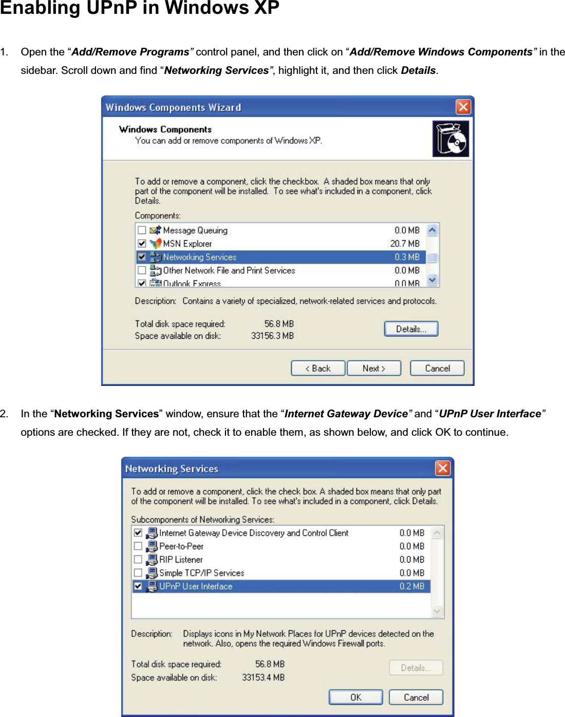
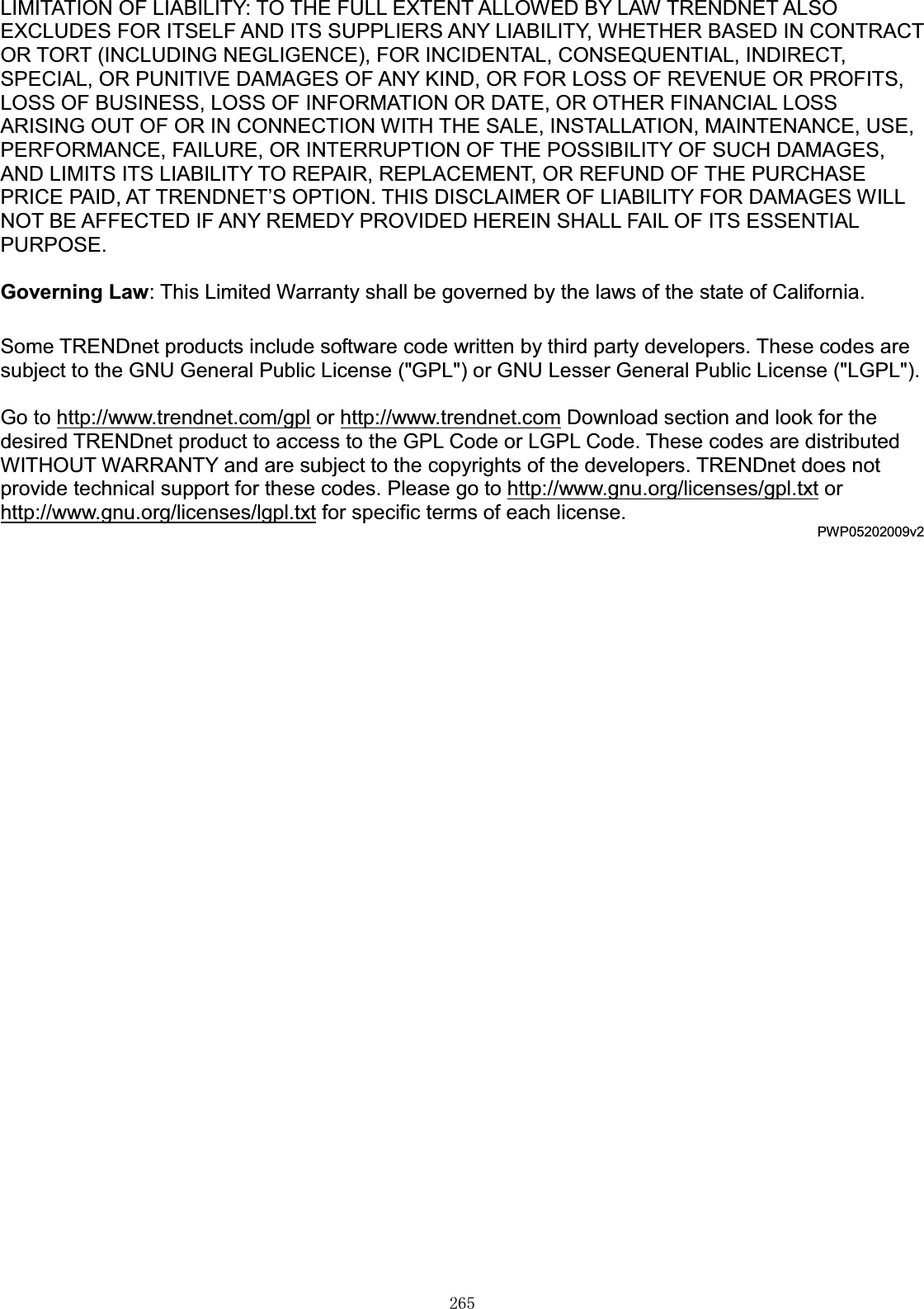
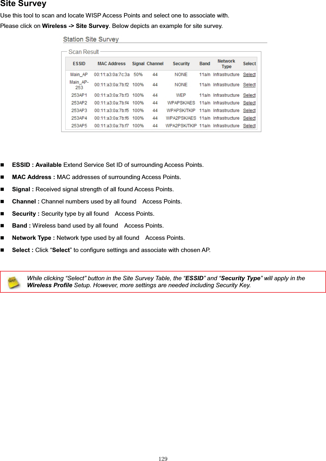
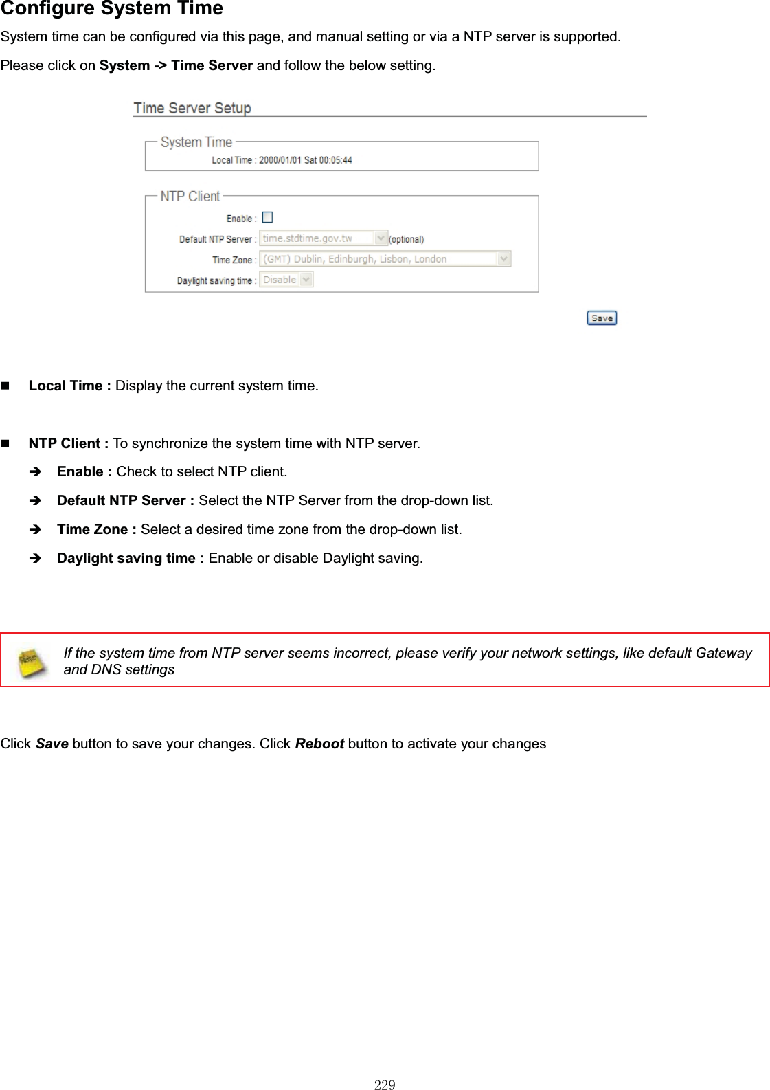
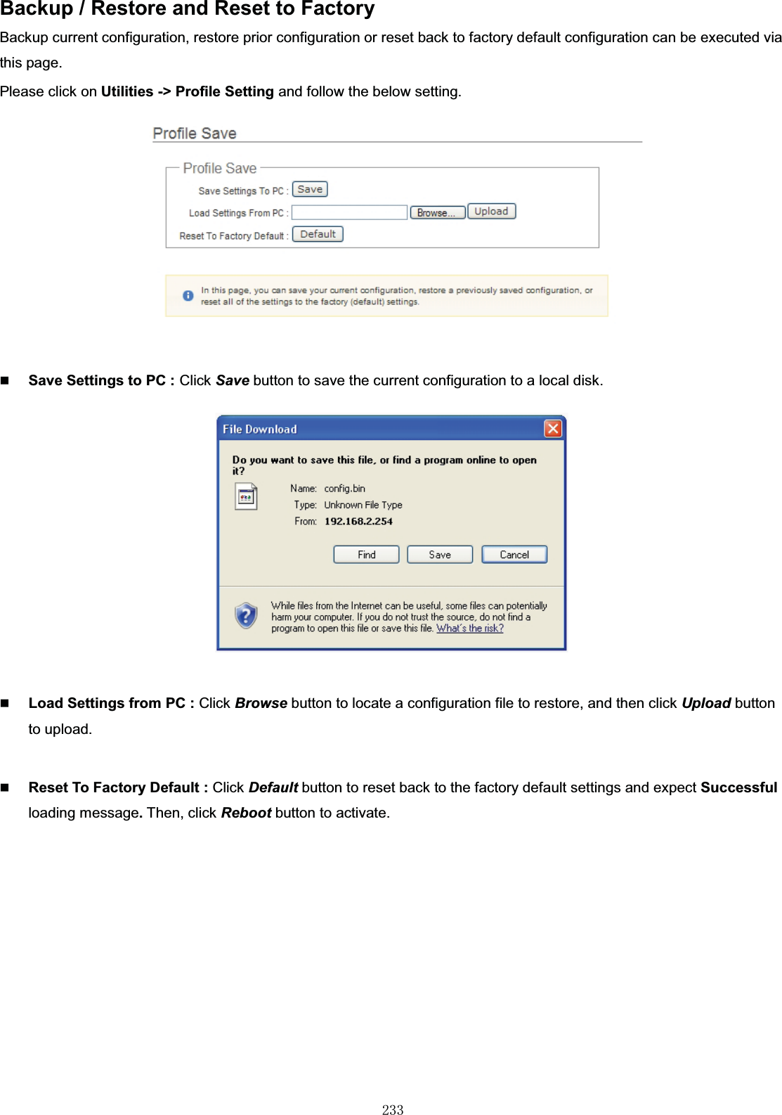
![㻞㻡㻤Block Field Valid CharactersDate Beacon Rate 1 ~ 255Fragment Threshold 256 ~ 2346RTS Threshold 1 ~ 2347Table B WEB GUI Valid Characters (continued)Block Field Valid CharactersVirtual AP Setup ESSID Length : 31Space0-9, A-Z, a-z~ ! @ # $ % ^ * ( ) _ + - { } | : < > ? [ ] / ; ` , . =Maximum Clients 1 ~ 32VLAN ID 1 ~ 4094WEP Key 10, 26 HEX chars or 5, 13 ASCII charsGroup Key Update Period >=60 secondsPMK Cache Period > 0 minutePre-Shared Key 8 ~ 63 ASCII chars; 64 HEX charsRadius Server IP IP Format; 1-254Radius Port 1 ~ 65535Shared Secret 8 ~ 64 charactersSession Timeout >= 60 seconds; 0 is disableWDS Setup WEP Key 10, 26 HEX chars or 5, 13 ASCII charsTKIP Key 8 ~ 63 ASCII chars; 64 HEX charsAES Key 8 ~ 63 ASCII chars; 64 HEX charsPeer's MAC Address 12HEX charsDescription 32 charsIP Filter Source Address IP Format; 1-254Source Mask 0 ~ 32Source Port 1 ~ 65535Destination Address IP Format; 1-254Destination Mask 0 ~ 32Destination Port 1 ~ 65535MAC Filter MAC address MAC Format; 12HEX charsVirtual Server Description 32 charsPrivate IP IP Formate; 1-254Private/ Public Port 1 ~ 65535DMZ IP Address IP Format; 1-254QoS/Parental ControlComment 32 charsMAC Address MAC Format; 12 HEX charsLocal/ Destination IP IP Formate; 1-254](https://usermanual.wiki/TRENDNET/TEW676APBO.Users-Manual-2/User-Guide-1543773-Page-135.png)