TSC Auto ID Technology RFWRN WiFi abgn module User Manual Manual
TSC Auto ID Technology Co., Ltd. WiFi abgn module Manual
UserManual.wiki
>
TSC Auto ID Technology
>
RFWRN User Manual
>
Manual
Contents
1.
Manual
2.
User Manual
3.
User Manual_Updated
4.
User Manual_V1
5.
(RF-WRN) UserMan_20161115
Manual
Navigation menu
Upload a User Manual
Namespaces
Wiki Guide
HTML
PDF
Info
Views
User Manual
Discussion / Help
Navigation
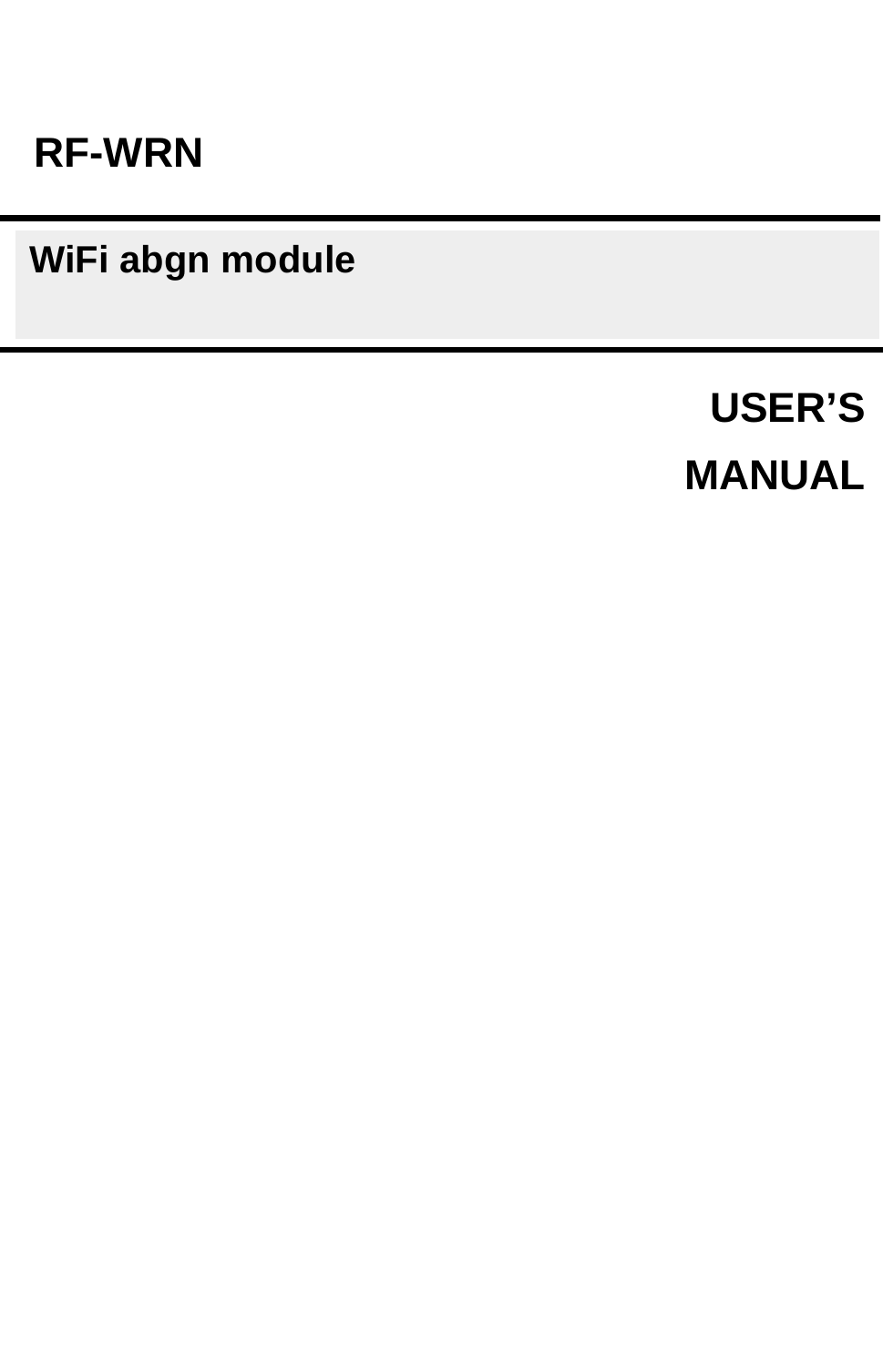
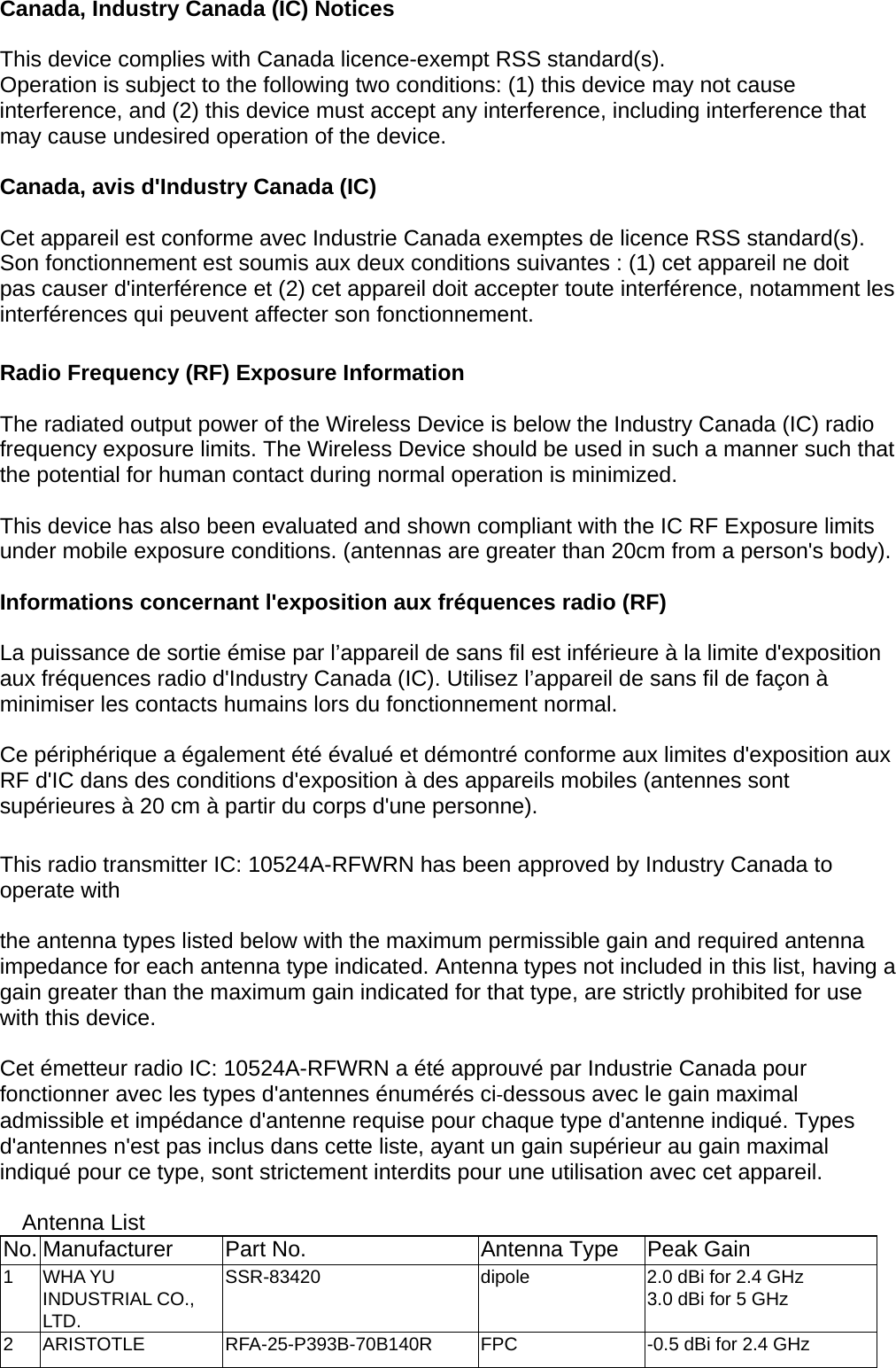

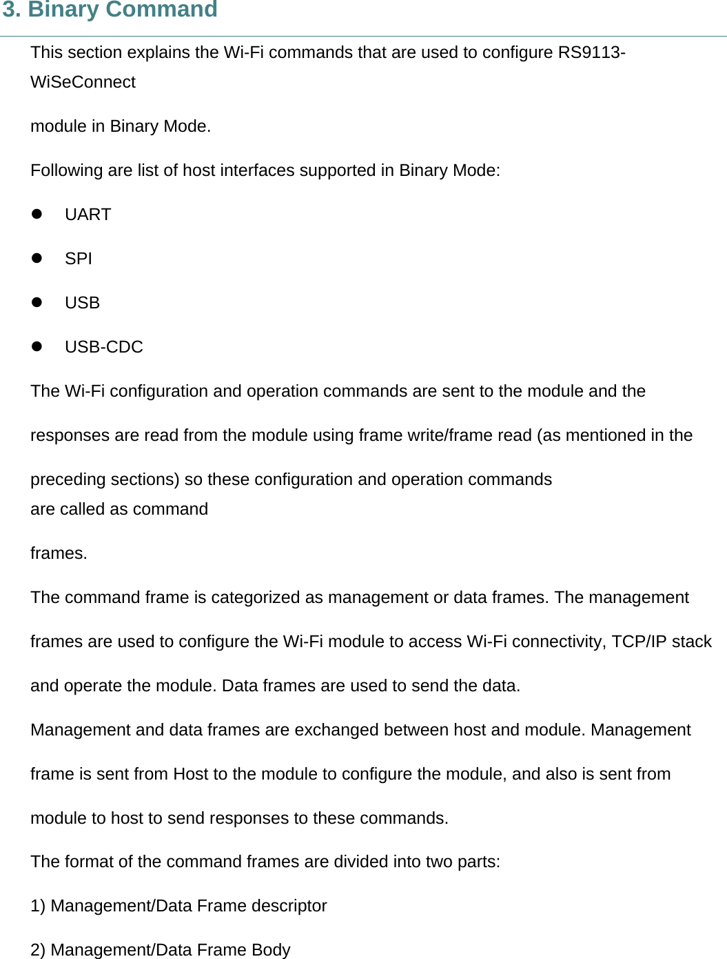
![2. AT command The Wi-Fi AT command set represents the frames that are sent from the Host to operate the RS9113-WiSeConnect Module. The command set resembles the standard AT command interface used for modems. All AT commands start with “at” and are terminated with a carriage return(‘\r’) and a new line(‘\n’) character. The AT command set for the RS9113-WiSeConnect Module starts with “at+rsi_” followed by the name of the command and any relevant parameters. In some commands, a ‘?’ character is used after the command to query data from the module. AppendixA:SampleFlowofCommandsforWi‐FioverUARTcaptures sample flow of commands to configure the module in various functional modes. Syntax of AT command: at+rsi_<command_name>[=][parameters][?]\r\n Example: at+rsi_command=< parameter1 >,< parameter2 >,< parameter3 >\r\n Each parameter should be separated by comma (,). NOTE:1)AllcommandsareissuedfromHosttomoduleasasequenceofASCIIcharacters.AllreturnmessagesfrommoduletoHostconsistofOKorERRORstrings,alongwithsomereturnparameters.ThereturnparametersmaybeASCIIorHexonacasebycasebasis.ERRORisaccompaniedby<Errorcode>.2)AcommandshouldNOTbeissuedbytheHostbeforereceivingtheresponseofapreviouslyissuedcommandfromthemodule.](https://usermanual.wiki/TSC-Auto-ID-Technology/RFWRN.Manual/User-Guide-2785661-Page-9.png)
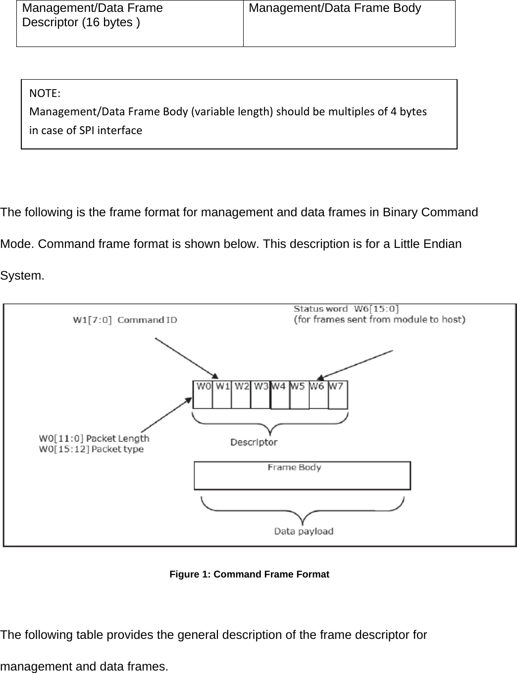
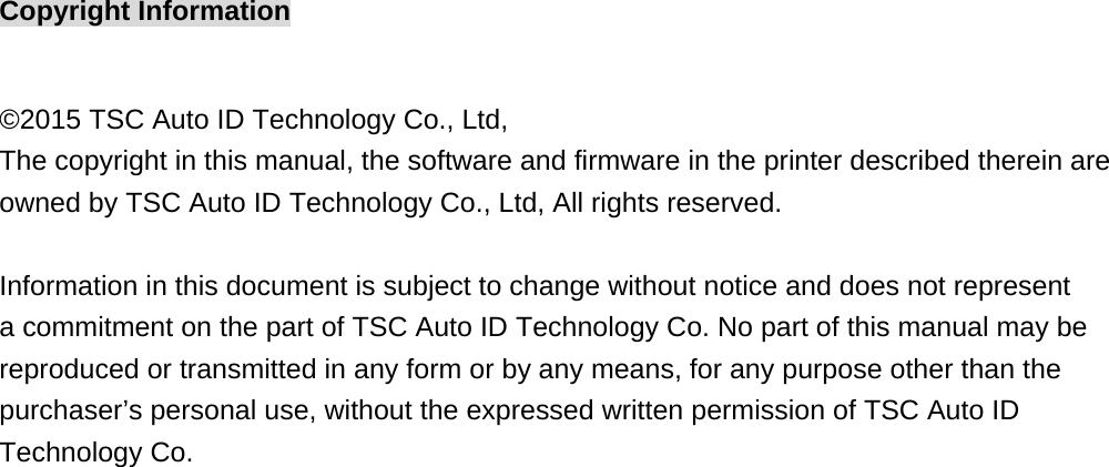
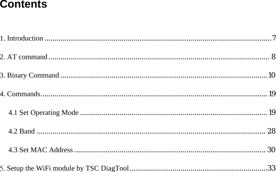
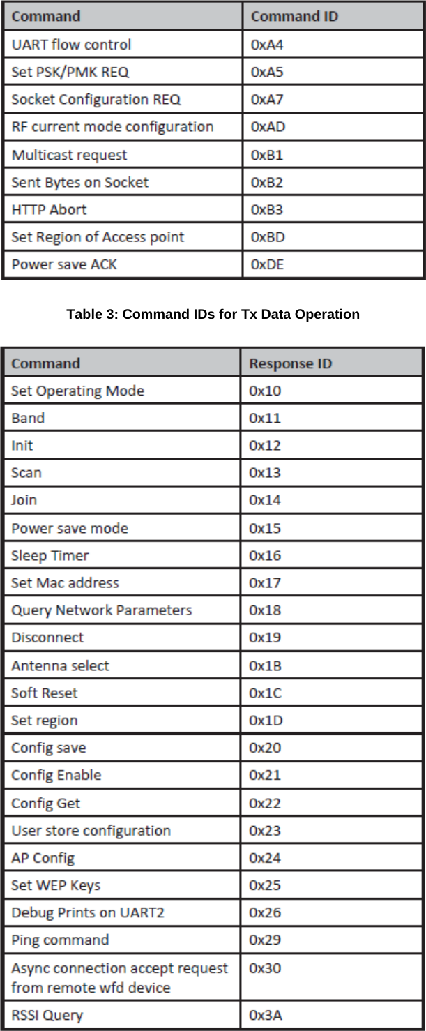
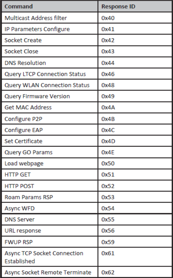
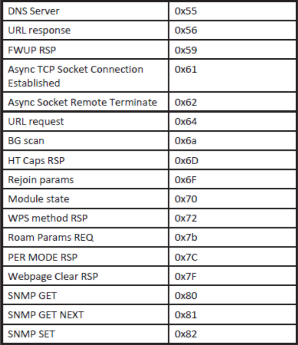
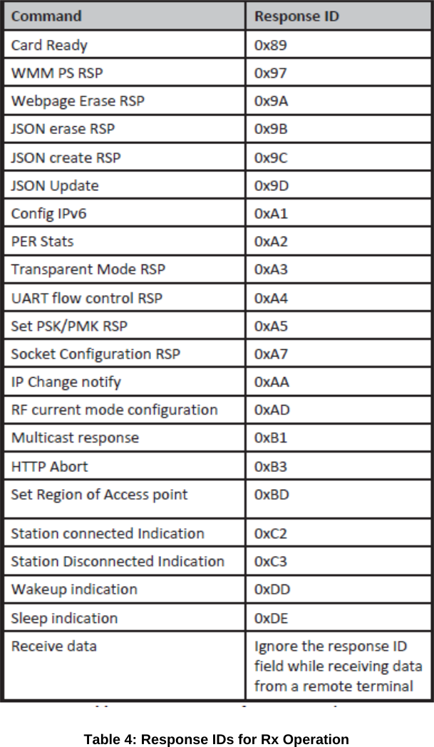
![Table 2: Frame Descriptor for Management/Data Frames in Binary Mode The management frames represent the command frames that are sent from the Host to the RS9113-WiSeConnect Module to configure for Wi-Fi access. These are frame write commands. The following are the types of management requests and responses and the corresponding codes. The first table below is applicable when the Host sends the frames to the module; the second table below is applicable when the module sends the frames to the host. The corresponding code is to be filled in W1 [7:0] mentioned in the table above.](https://usermanual.wiki/TSC-Auto-ID-Technology/RFWRN.Manual/User-Guide-2785661-Page-13.png)
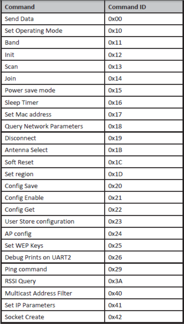
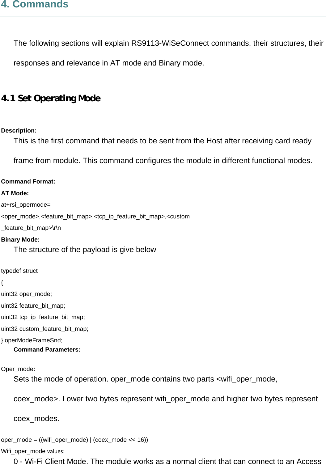
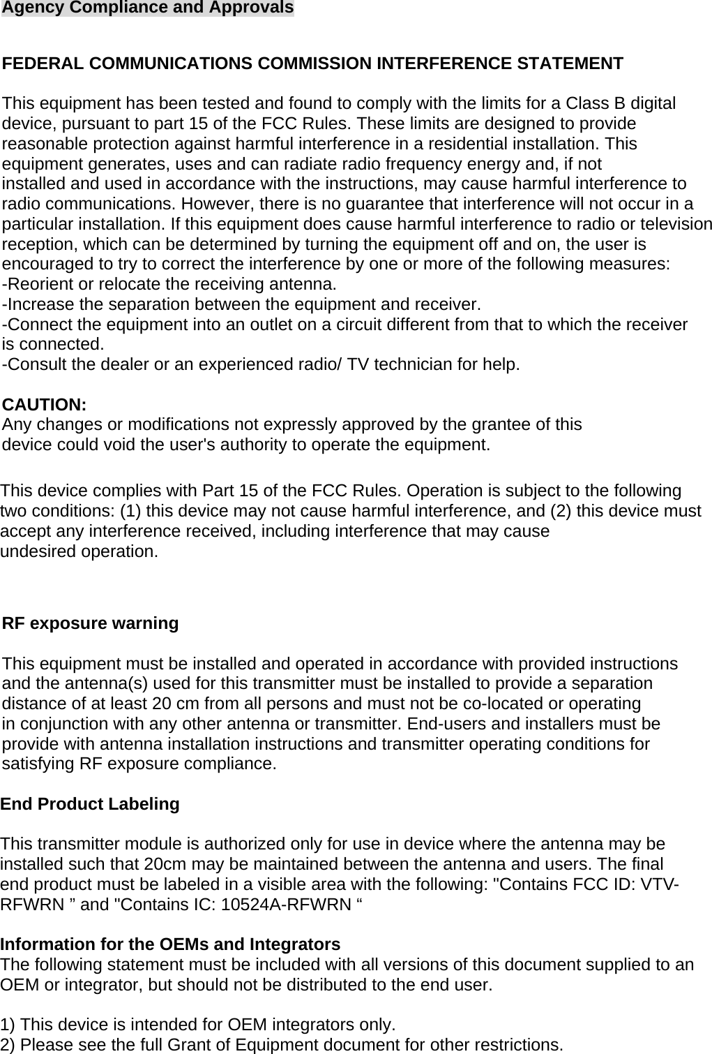
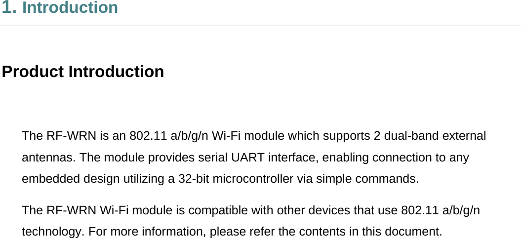
![BIT 3 : Enable/Disable BTLE mode. 0 – Disable BTLE mode 1 – Enable BTLE mode NOTE: In BTLE mode, need to enable BT mode also. Following table represents possible coex modes supported: feature_bit_map: this bitmap is used to enable following WLAN features: feature_bit_map[0]- To enable open mode 0 - Open Mode Disabled 1- Open Mode enabled (No Security) feature_bit_map[1]- To enable PSK security 0 - PSK security disabled 1 - PSK security enabled feature_bit_map[2]-To enable Aggregation 0-Aggregation disabled 1-Aggregation enabled feature_bit_map[3]-To enable LP GPIO hand shake 0 – LP GPIO hand shake disabled 1 – LP GPIO hand shake enabled feature_bit_map[4]-To enable ULP GPIO hand shake 0 – ULP GPIO hand shake disabled NOTE:Incoexistencemode(3,5,13)modulesupportsonlyWLANclientmode(Openmode,PSKsecurity).EmbeddedTCP/IPstackisnotsupportedinWLAN+BTmode.NOTE:InWLAN+BLEmodemaximumnumberofsocketssupportedare2NOTE:InWLAN+ZBmodemaximumnumberofsocketssupportedare8NOTE:Incoexistencemode(0)modulesupportsallWLANmodesandembeddedTCP/IPstack.](https://usermanual.wiki/TSC-Auto-ID-Technology/RFWRN.Manual/User-Guide-2785661-Page-22.png)
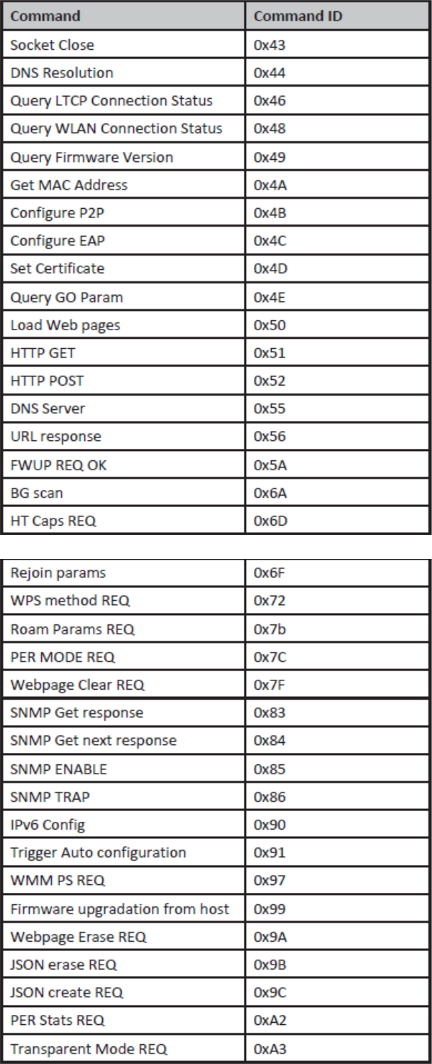
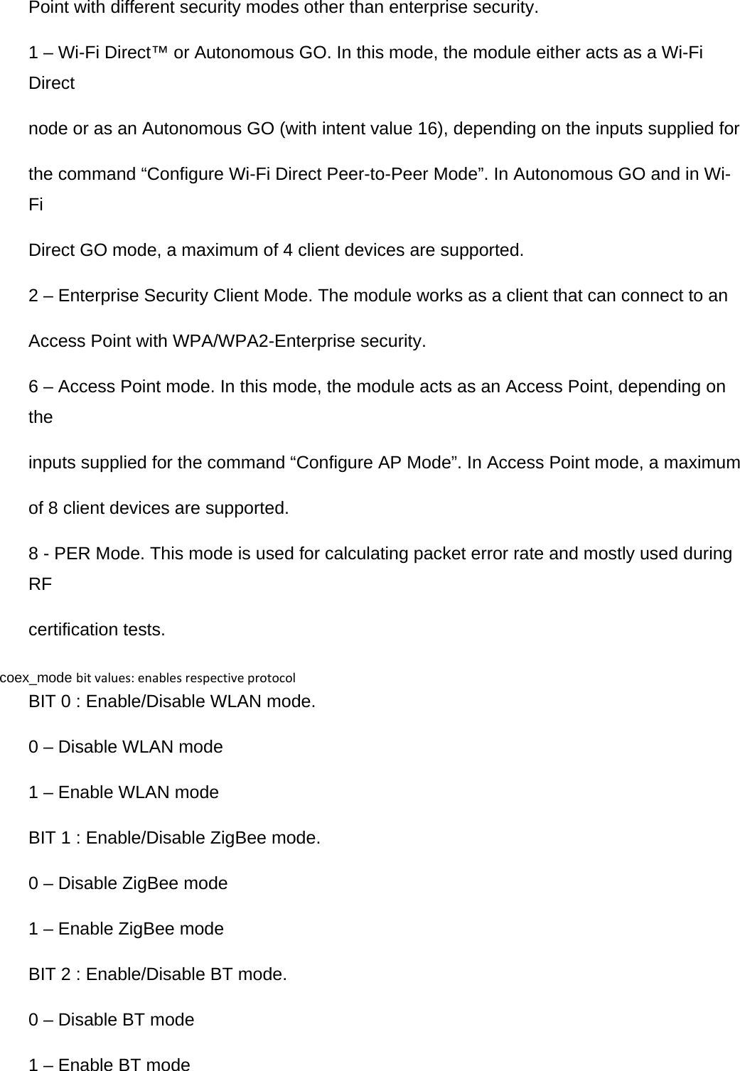
![1 – ULP GPIO hand shake enabled feature_bit_map[5]-To select module to host wakeup pin 0 – GPIO_21 is used as module to host wakeup pin 1 – ULP_GPIO_1 is used as module to host wakeup pin feature_bit_map[6]-To select RF supply voltage 0 – RF voltage is set to 1.9V 1 – RF voltage is set to 3.3V feature_bit_map[7:31]- Reserved. Should set to be ‘0’ tcp_ip_feature_bit_map: To enable TCP/IP related features. tcp_ip_feature_bit_map[0]- To enable TCP/IP bypass 0 - TCP/IP bypass mode disabled 1 - TCP/IP bypass mode enabled tcp_ip_feature_bit_map[1]- To enable http server 0 - HTTP server disabled 1 - HTTP server enabled tcp_ip_feature_bit_map[2]- To enable DHCPv4 client 0 - DHCPv4 client disabled 1 - DHCPv4 client enabled tcp_ip_feature_bit_map[3]- To enable DHCPv6 client 0 - DHCPv6 client disabled 1 - DHCPv6 client enabled tcp_ip_feature_bit_map[4]- To enable DHCPv4 server 0 - DHCPv4 server disabled 1 - DHCPv4 server enabled tcp_ip_feature_bit_map[5]- To enable DHCPv6 server 0 - DHCPv6 server disabled 1 - DHCPv6 server enabled tcp_ip_feature_bit_map[6]- To enable Dynamic update of web pages (JSON objects) 0 - JSON objects disabled 1 - JSON objects enabled tcp_ip_feature_bit_map[7]- To enable HTTP client 0 - To disable HTTP client 1 - To enable HTTP client tcp_ip_feature_bit_map[8]- To enable DNS client 0 - To disable DNS client NOTE:feature_bit_map[0], feature_bit_map[1] arevalidonlyinWi‐Ficlient](https://usermanual.wiki/TSC-Auto-ID-Technology/RFWRN.Manual/User-Guide-2785661-Page-23.png)
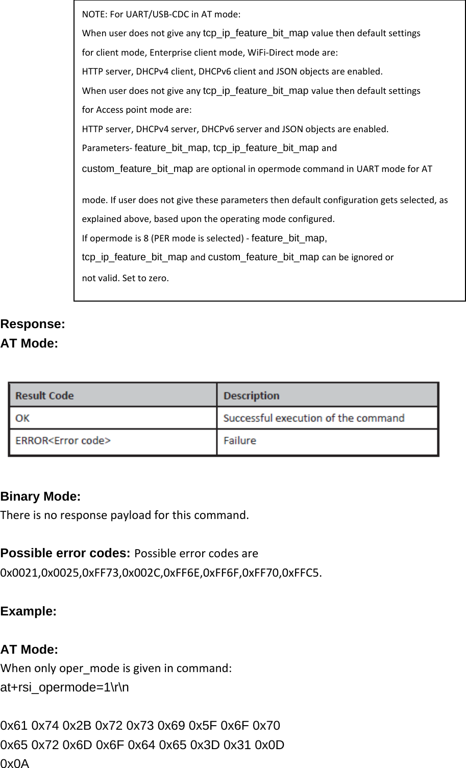
![1 - To enable DNS client tcp_ip_feature_bit_map[9]- To enable SNMP agent 0 - To disable SNMP agent 1 - To enable SNMP agent tcp_ip_feature_bit_map[10]- To enable SSL 0 - To disable SSL 1 - To enable SSL tcp_ip_feature_bit_map[11]- To enable PING from module(ICMP) 0 - To disable ICMP 1 - To enable ICMP tcp_ip_feature_bit_map[12]- To enable HTTPS Server 0 - To disable HTTPS Server 1 - To enable HTTPS Server tcp_ip_feature_bit_map[14]- To send configuration details to host on submitting configurations on wireless configuration page 0 - Do not send configuration details to host 1 - Send configuration details to host tcp_ip_feature_bit_map[15]- To enable FTP client 0 - To disable FTP client 1 - To enable FTP client tcp_ip_feature_bit_map[16]- To enable SNTP client 0 - To disable SNTP client 1 - To enable SNTP client tcp_ip_feature_bit_map[17]- To enable IPv6 mode 0 - To disable IPv6 mode 1 - To enable IPv6 mode IPv6 will also get enabled if DHCP v6 client/DHCP v6 server is enabled irrespective of tcp_ip_feature_bit_map[17].tcp_ip_feature_bit_map[19]- To MDNS and DNS-SD 0 - To disable MDNS and DNS-SD 1 - To Enable MDNS and DNS-SD tcp_ip_feature_bit_map[13], tcp_ip_feature_bit_map[18], tcp_ip_feature_bit_map[20:31]-All set to ‘0’. NOTE: SSL(tcp_ip_feature_bit_map[10], tcp_ip_feature_bit_map[12]) is supported only in opermode 0 NOTE: tcp_ip_features supported in coex mode WLAN+BT:TCPIPBypassWLAN+BLE:TCPIPBypass,DHCPV4Client,HTTPClient,DNSClient,FTPClientWLAN+ZB:TCPIPBypass,HTTPServer,DHCPV4Client,DHCPV6Client,HTTPClient,DNSClient,SNMPclient,FTPClientcustom_feature_bit_map:](https://usermanual.wiki/TSC-Auto-ID-Technology/RFWRN.Manual/User-Guide-2785661-Page-24.png)
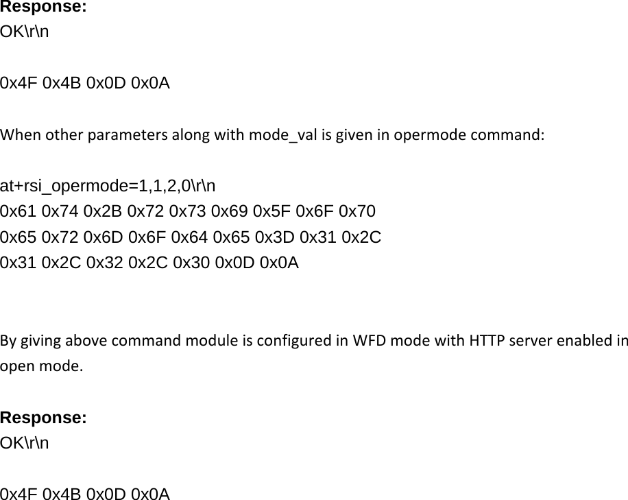
![This bitmap used to enable following custom features: BIT[2]: If this bit is set to ‘1’, the DHCP server behavior, when the module is in AP mode, changes. The DHCP server, when it assigns IP addresses to the client nodes, does not send out a Gateway address, and sends only the assigned IP and Subnet values to the client. It is highly recommended to keep this value at ‘0’ as the changed behavior is required in only very specialised use cases and not in normal AP functionality. The default value of this bit is ‘0’. BIT[5]: If this bit is set to ‘1’, Hidden SSID is enabled in case of AP mode. The default value of this bit is ‘0’. BIT[6]:To enable/disable DNS server IP address in DHCP offer response in AP mode. 1- In AP mode, DHCP server sends DNS server IP address in DHCP offer 0- Not to include DNS server address in DHCP offer response BIT[8]: ‐ Enable/Disable DFS channel passive scan support 1- Enable 0-Disable BIT[9] : –To Enable/disable LED(GPIO_16) after module initialization(INIT). 1- Enable LED support 0– Disable LED support BIT[10]: Used to enable/disable Asynchronous messages to host to indicate the module state. 1- Enable asynchronous message to host 0-Disable asynchronous message to host BIT[11] :To enable/disable packet pending (Wakeon wireless) indication in UART mode 1 – Enable packet pending indication 0- Disable packet pending indication BIT[12]:Used to enable or disable AP blacklist feature in client mode during roaming or rejoin. By default module maintains AP blacklist internally to avoid some access points. 1 – Disable AP black list feature 0 – Enable AP black list feature BIT[13-16]:Used to set the maximum number of stations or client to support in AP or Wi-Fi Direct mode. Possible values are 1 to 8 in AP mode and 1 to 4 in Wi-Fi Direct mode. Note1: If these bits are not set, default maximum clients supported is set to 4. BIT[17] :to select between de-authentication or Null data (with power management bit set) based roaming, Depending on selected method station will send deauth or Null data to connected AP when roam from connected AP to newly selected AP. 0 – To enable de-authentication based roaming 1 – To enable Null data based roaming BIT[18]: Reserved BIT[19]: Reserved BIT[20]: Used to start/stop auto connection process on bootup, until host triggers it using Trigger Auto Configuration command](https://usermanual.wiki/TSC-Auto-ID-Technology/RFWRN.Manual/User-Guide-2785661-Page-25.png)
![1 – Enable 0 – Disable BIT[22]: Used to enable per station power save packet buffer limit in AP mode. When enabled, only two packets per station will be buffered when station is in power save 1 – Enable 0 – Disable BIT[23] :To enable/disable HTTP/HTTPs authentication 1 - Enable 0 – Disable BIT[24]: To enable/disable higher clock frequency in module to improve throughputs 1 - Enable 0 – Disable BIT[25]: To give HTTP server credentials to host in get configuration command 1 – To include HTTP server credentials in get configuration command response 0 – To exclude HTTP server credentials in get configuration command response BIT[26]:To accept or reject new connection request when maximum clients are connected in case of LTCP. 1 - Reject 0 – Accept By default this bit value is zero. When BIT[26] is zero: For a LTCP socket when maximum clients are connected if a new connection request is received, then this connection request will not be rejected. Instead module will maintain this connection request in LTCP pending list. This request will be served when any of the connected client is disconnected. When BIT[26] is set: For a LTCP socket when maximum clients are connected if a new connection request is received, then this connection request will be rejected immediately. Module will not maintain this connection request in LTCP pending list. BIT[0:1],BIT[3:4],BIT[7],BIT[21],BIT[31:27]: Reserved, should be set to all ‘0’.](https://usermanual.wiki/TSC-Auto-ID-Technology/RFWRN.Manual/User-Guide-2785661-Page-26.png)
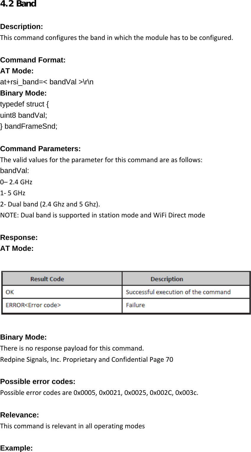
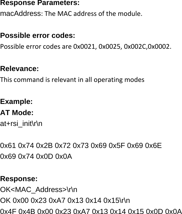
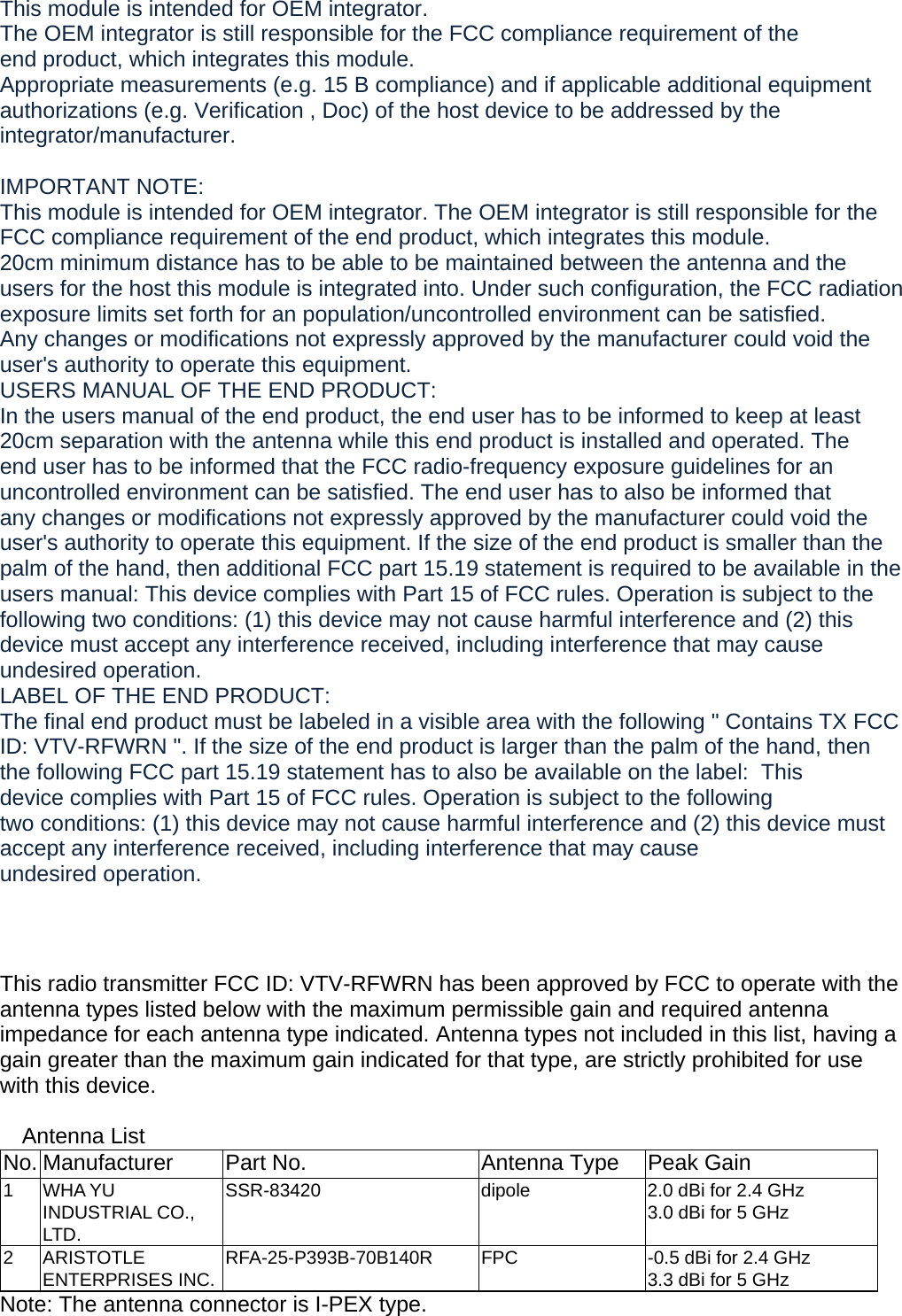
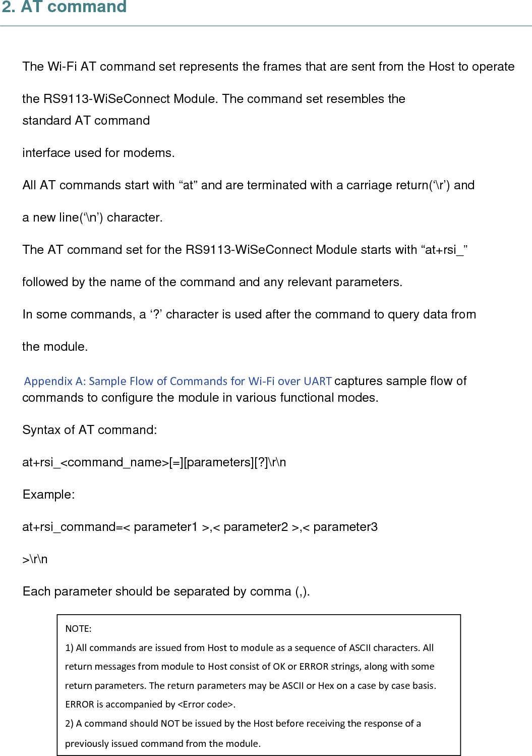
![4.3 Set MAC Address Description: Thiscommandsetsthemodule’sMACaddress.Thiscommandhastobeissuedbeforebandcommand. Command: AT Mode: at+rsi_setmac=< macAddr >\r\n Binary Mode: typedef struct { uint8 macAddr[6]; }setMacAddrFrameSnd; Command Parameters: macAddr –Macaddresstobesetformodule. Response: AT Mode: Binary Mode: Thereisnoresponsepayloadforthiscommand. Possible error codes: Possibleerrorcodesare0x0021,0x0025,0x002C. Relevance: Thiscommandisrelevantinalloperatingmodes. Example:](https://usermanual.wiki/TSC-Auto-ID-Technology/RFWRN.Manual/User-Guide-2785661-Page-31.png)
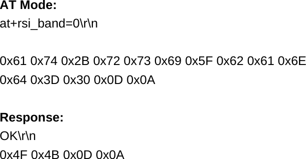
![AT Mode: at+rsi_setmac=001122334455\r\n 0x61 0x74 0x2B 0x72 0x73 0x69 0x5F 0x73 0x65 0x74 0x6D 0x61 0x63 0x3D 0x30 0x30 0x31 0x31 0x32 0x32 0x33 0x33 0x34 0x34 0x35 0x35 0x0D 0x0A Response: OK\r\n 0x4F 0x4B 0x0D 0x0A 8.4 Init Description: Thiscommandprogramsthemodule’sBasebandandRFcomponentsandreturnstheMACaddressofthemoduletothehost. Command: AT Mode: at+rsi_init\r\n Binary Mode: NoPayloadrequired. Command Parameters: NoparametersResponse: AT Mode: Binary Mode: typedef struct { uint8 macAddress[6]; }rsi_initResponse;](https://usermanual.wiki/TSC-Auto-ID-Technology/RFWRN.Manual/User-Guide-2785661-Page-32.png)