Tagmaster LRXX RFID Communicator User Manual DS S1500
Tagmaster AB RFID Communicator DS S1500
Contents
Data sheets
Copyright
The copyright/ownership of this document is and will remain ours. The document must not be used without our authorization or brought to the knowledge of a third party. TagMaster AB.
Disclaimer
The information in this document is subject to change without notice. While the information contained herein is assumed to be accurate, TagMaster AB assumes no responsibility for any errors
or omissions.
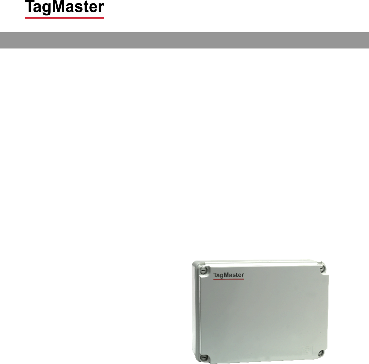
S1500 / S1501 Reader
User programmable Read/Write station
DATA SHEET
DOC NO. 06-xxx 01
TagMaster AB S1500 / S1501 Reader Data Sheet Issue 01
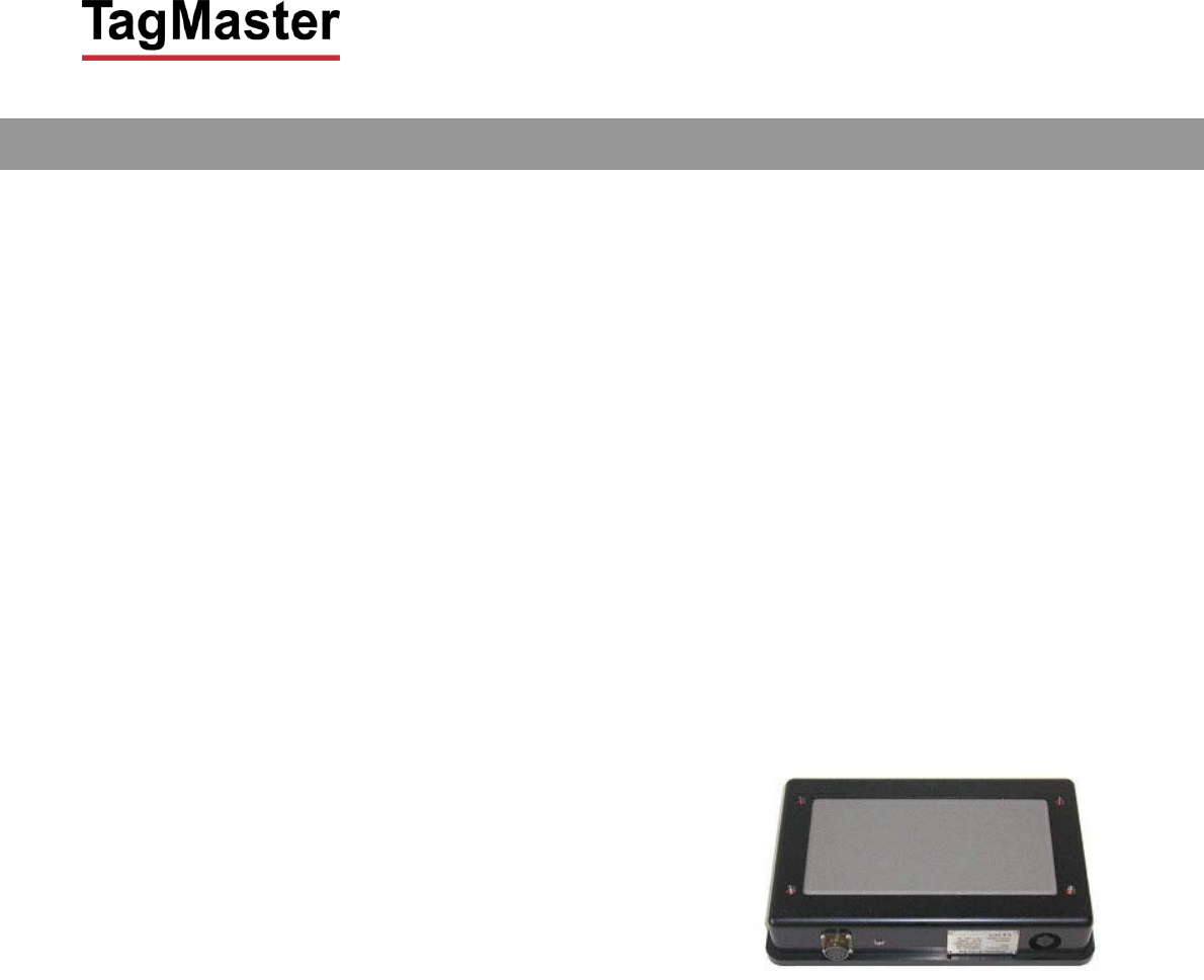
Functional description
S1500 readers are a 2.45 GHz circular polarised
read/write station for TagMaster RFID tags.
Reading distance is typically up to 6 metres. The
reader has 99 RF channels to eliminate
interference of other nearby readers. Transmitted
power and reception sensitivity is also adjustable
with SW commands for optimising any
installation.
S1500 has a movement detection function for
detecting people and vehicles, or even smaller
objects, even if not using a tag. It can determine
their moving speed in approaching or retreating
directions.
S1500 is user programmable and has a large
memory for application programs and built in
database functions for fast, customised and
efficient stand-alone operation. User software is
downloaded and saved in EEPROM through a
serial communication line. If user programming is
not required, there is a ready-to-use standard
application SW in the reader.
A local database in EEPROM can be loaded with
over 15,000 tag entries for extremely fast read-
validate-activate response times.
The ConfiTalk protocol is used for serial
communication in a polled RS485 network or
point-to-point in RS232 connections. There are
ConfiTalk communication drivers available for
95/98/ME and NT/2000/XP with interface for
C/C++, Delphi and Visual Basic.
S1500 has two serial ports, a DTMF port for
keypads, LED interfaces, relay, parallel I/O
(emulating magcard data as an option).
A control panel with a 7-segment LED display,
two push buttons, a three colour LED, a buzzer
and a reset button is available for local
configuration and start up of test programs as
installation aids. The unit can also be configured
using a hand held computer or terminal
connected locally.
S1500 is sealed from water spray and dust. Non-
corrosive materials are used in external parts.
Connections are made through rubber bushings,
or via cable glands in a steel back plane.
Jackable screw connectors connect the wires.
Built in DC/DC converters tolerate noisy voltages,
provide low power consumption (3W) and can be
set to 24 as well as 12 VDC
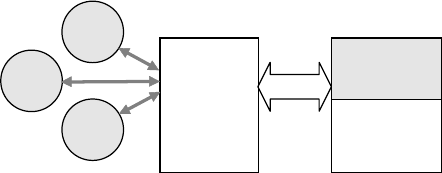
Microwave/Antenna block
Processor block
I/O block
DC supply
RS 485
RS 232a
RS 232b
DTMF/LED
Relay
Opto I/O
Radiated 2.45 GHz signal
6 m reading range
R
ange/channel setting by SW
Tag programming
M
ovement detection at up to 5 m
3-colour LED and buzzer
R
S232 and 2/4 wire RS485
3 parallel in, 2 parallel out
optoisolated. Relay and
tamper switches
E
MI tolerant DC/DC conv.
24V or 12V powering
User programmable
C, Delphi and VB drivers
Flash EEPROM database
D
TMF and LED interface
M
aintenance functions
TagMaster AB S1500 / S1501 Reader Data Sheet Issue 01
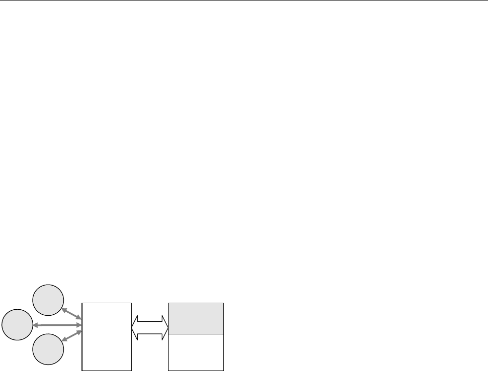
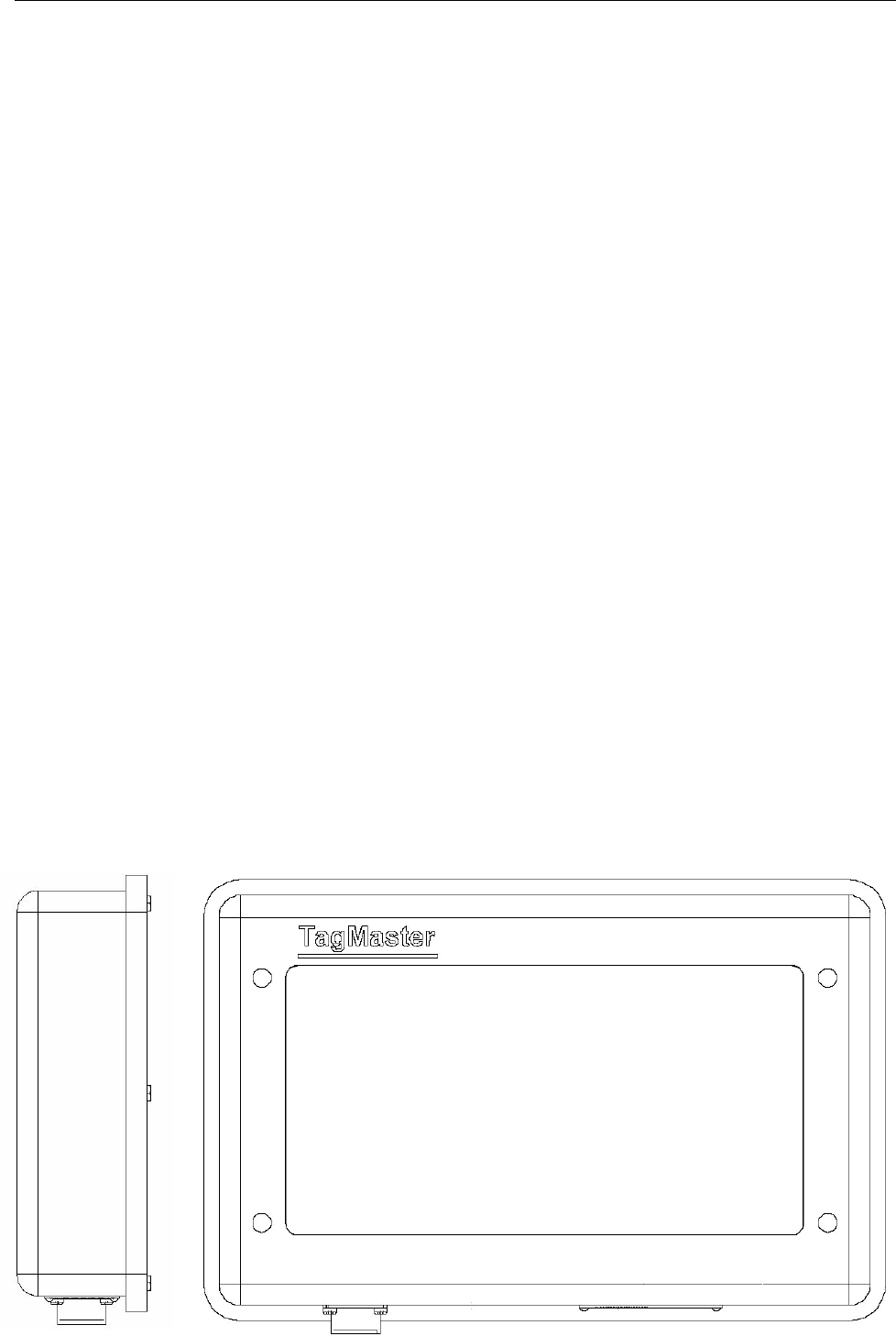
General
S1500 comprises a plastic cover and a metal
chassis for two PC boards, where the upper
position carries a standard board and the
lower is for an option board. A rubber gasket
seals the unit.
The standard board includes a Processor and
I/O block with analogue and digital circuits,
and is integrated with a Microwave and
Antenna block.
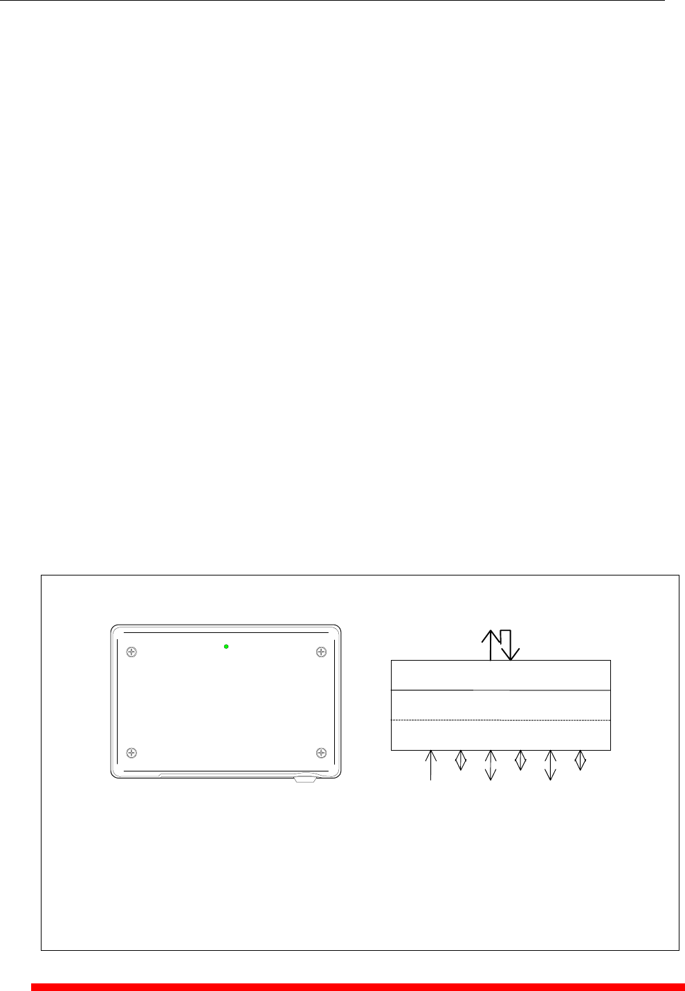
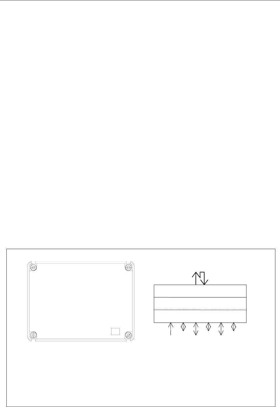
The antenna system is circular polarised and
radiates through the front cover, with a lobe
that is directed perpendicularly to the front
surface of S1500. The lobe shape can be
described as an ellipsoid with a circular cross
section, as shown in the figure below.
CONFIDENT
The reading and writing distances depend on
the tag type and on the power and sensitivity
SW settings. Typically, S1500 can read
TagMaster tags at up to 6 m distance. See
Reading/Writing range for details.
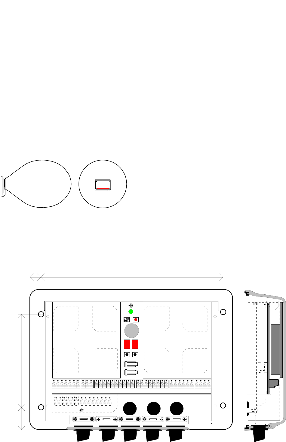
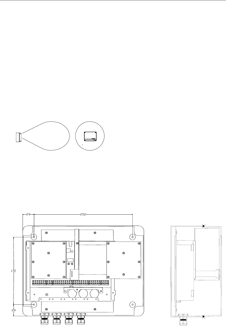
When dismounting the cover, it separates
from the cable inlets to conveniently operate
the unit also without cover. Screw connectors
are jackable and in logical groups, i.e. it is not
needed to disconnect each wire to replace the
electronics.
J1 DTMF, LED, external tamper line
J2 RS232 for terminal
J3 RS232 and RS 485 for host
J4 Parallel out and relay
J5 Parallel in
J6 DC supply
To hide the cables, S1500 can be connected
via cable glands in the back plane. Dual
tamper switches monitor that the cover is
closed. When removed, a software as well as
hardware alarm is generated.
For service and setup purposes there is a
control panel with a 7-segment LED display, 2
control buttons, a reset button, a LED and a
buzzer. There are also jumpers for RS232/485
and 12/24V selection.
A corrosion resistant mounting bracket that
gives additional sealing for rough
environments is separately available. It fits the
mounting holes of S1500, and has a flexible
joint for easy adjustment to different mounting
angles.
J1 J2 J3 J4 J5 J6
8,7 236,6
120,0
23,7
Diameter of holes: 4,2 mm
TagMaster AB S1500 / S1501 Reader Data Sheet Issue 01
Copyright
The copyright/ownership of this document is and will remain ours. The document must not be used without our authorization or brought to the knowledge of a third party. TagMaster
AB.
Disclaimer
The information in this document is subject to change without notice. While the information contained herein is assumed to be accurate, TagMaster AB assumes no responsibility for
any errors or omissions.
Reading/writing range
The maximum reading or writing range is defined
as the maximum distance along the radiation axis
where the tag can be communicated when the tag
and reader face each other and when there is free
space in between.
The free space reading range for S1500 is up to
more than 6 m (20 Ft).
In a typical installation the reading range is up to
4m (13 Ft)
Writing range is up to 0.25 m (0.8 Ft)
The reading range depends on the tag reflectivity,
the data speed (high/low), power output and
sensitivity settings.
If using low power and/or low sensitivity the
reading range is reduced according to the
following table.
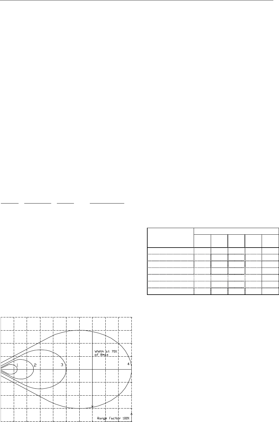
Range Sensitivity Power Range factor
4 HIGH HIGH 100%
3 HIGH LOW 50%
2 LOW HIGH 25%
1 LOW LOW 12%
Writing must be done at high power. The writing
range is normally not affected by speed and
sensitivity settings.
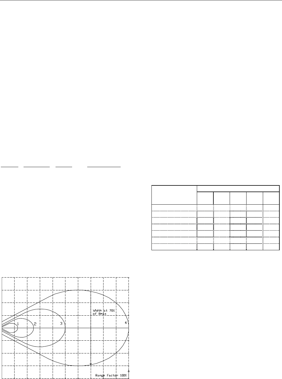
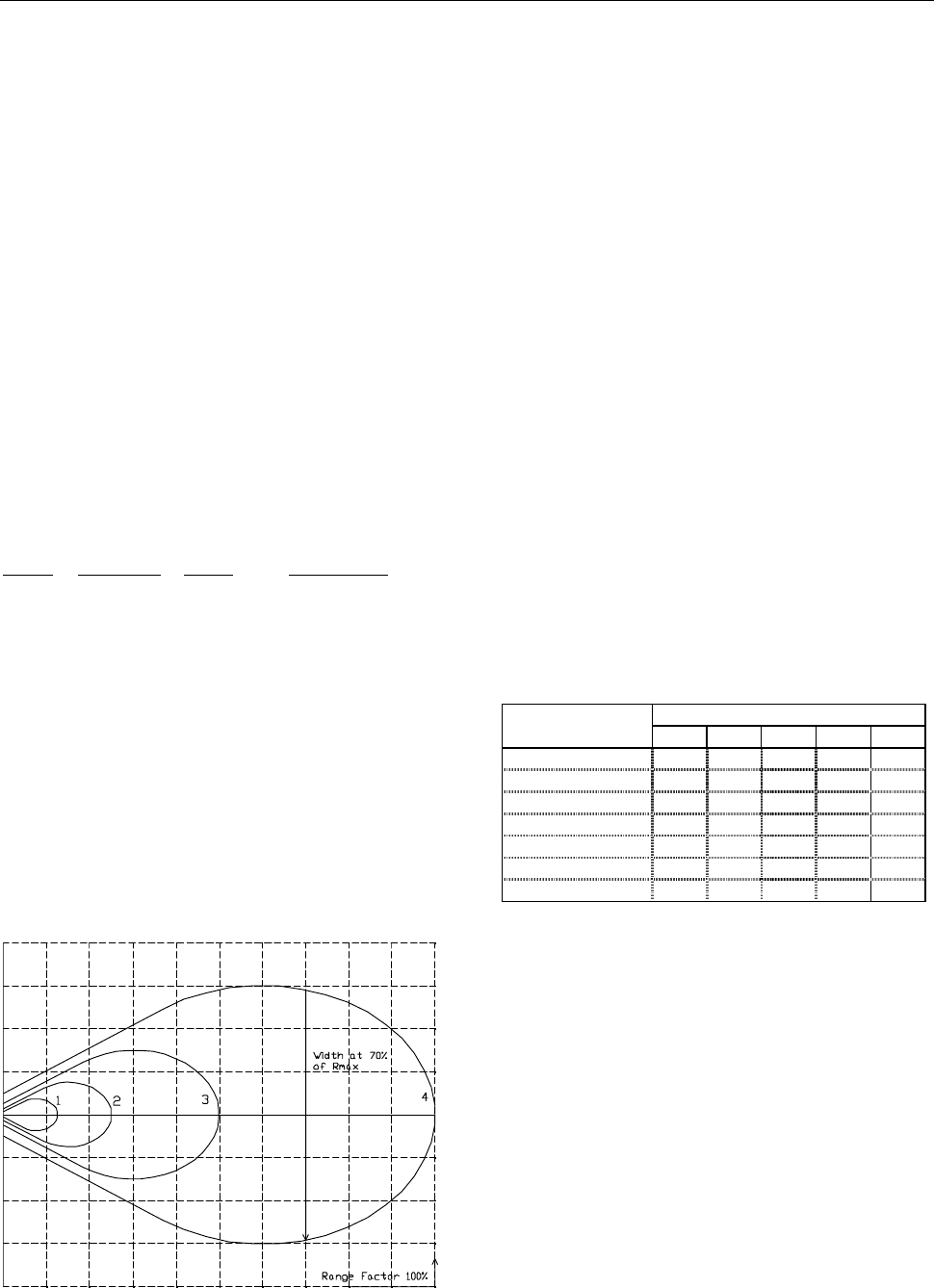
Lobe width
The lobe diagram shows, in a proportional scale,
the approximate lobe shapes of the S1500 and
S1501 readers.
Curves 4, 3, 2 and 1 show areas for safe reading
for the four different combinations of power and
sensitivity.
Example: Your reading range has been calculated
to 4.0 meters, meaning each square in the
diagram is 4.0/10=0.4 meters. The lobe width at
70% range is then 5.5 squares * 0.4 = 2.2 meters.
The diagram concerns a free space installation,
and does not take into account possible
influences from signal reflections or attenuating
structures.
For reliability reasons, it is recommended that
tags are passing at 70 % or less of specified
reading and writing range.
Reading/writing time
The time for reading and writing tags are specified
in the tag data sheets. Please refer to the data
sheet of the specific tag concerned.
Passage speed
The table shows the maximum allowed passage
speed in km/h for combinations of tag reading
time and lobe widths.
Lobe width [m]
Reading time
[ms]
1 1.5 2.0 2.5 3.0
20 180 270 360 450 540
50 72 108 144 180 216
70 51 77 103 129 154
100 36 54 72 90 108
130 28 42 56 69 83
150 24 36 48 60 72
200 18 27 36 45 54
Tag orientation
Thanks to the circular polarisation, the reading
and writing ranges are independent from the
rotational orientation around the radiation axis.
The reading time for the tag, can be found in the
tag datasheets. If the ID tag is tilted in relation to
the reader, a range reduction may occur. Since
this effect depends mainly on the specific
installation, it is recommended that a test is made.
S1500 can be set to a "read beep" mode to
conveniently check out the reading range.
Movement detection
S1500 detects a moving person or car at up to 5
meters (16Ft) distance, even when moving slowly.
The reader senses if the object is approaching or
moving away from the reader, and at what radial
TagMaster AB S1500 / S1501 Reader Data Sheet 2006-06-07
speed. The detection threshold can be set to
different sensitivity levels.
Software
The readers are delivered with the pre-installed
software Pyramid for standard applications.
However, you can easily develop your own
application software to be executed inside the
reader. This will give you the full power of
controlling the reader operation for flexible
solutions and fast response times.
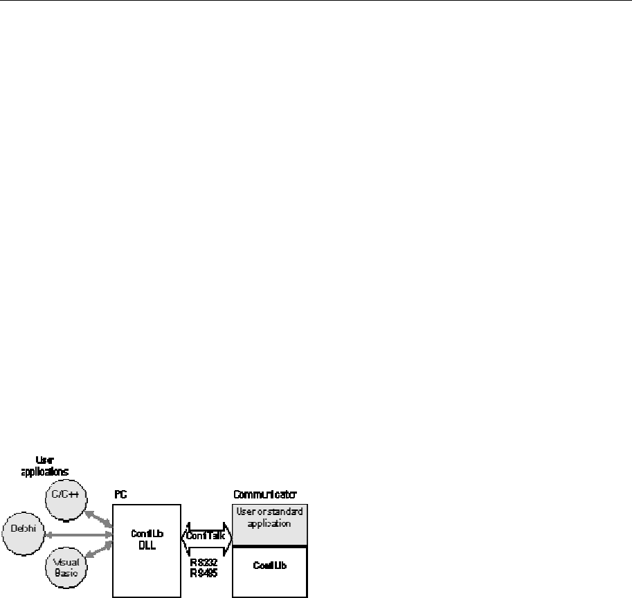
User application development
For user application development there are
complete software development kits (SDK)
including compilers, loaders, tools, drivers and
libraries supporting the complete development
phase for reader applications as well as PC
applications.
ConfiLib
ConfiLib
DLL
User or standard
application
Delphi
Visual
Basic
C/C++
User
applications
PC Communicator
ConfiTalk
RS232
RS485
Reader applications are developed in a PC
environment with the cross compiler ConfiComp
and can be executed in the PC for testing and
debugging. The complete software is finally
downloaded, using ConfiLoad, to the reader for
permanent storage in EEPROM. PC applications
are developed with any PC software development
tool. For application programmers a ConfiTalk
Commander is available for training and low level
communications management.
ConfiLib
ConfiLib is a function library with hundreds of
functions for reader management and ConfiTalk
protocol handling. ConfiLib exist in versions both
for readers and PC environments including DOS,
Windows 3.1, 95/98/ME and NT/2000/XP.
The reader version of ConfiLib is a function library
package in C language. For PC environments, the
ConfiLib API comes as dynamic link libraries
(DLL) with C/C++ interface. There are also
separate interface modules for Visual Basic and
Delphi available. Typical functions include
read/write/format tags, read/write/search
database, HW/SW configuration, read/write I/O,
ConfiTalk send/receive, timers, buffers, mail
management, etc.
ConfiTalk
ConfiTalk is the standard serial communications
protocol used by the readers. The protocol
transfers data to and from a reader and handles
flow control, retransmissions, checksums and
data transparency. It can be used both for point-
to-point and multidrop networks, using a polling
procedure.
ConfiTalk can also be replaced by a user defined
protocol.
Pyramid application
Pyramid application operates stand-alone reading
tags, validating according to a downloaded
database white list, activating relays for valid tags
and producing logs for a PC to collect on- or off-
line. Pyramid can also sense movements of
people and vehicles using the movement
detection.
Events
Following events may trig actions:
• A tag is read
• A tag is read and found in the database
(validated)
• A movement is detected
Actions
For each event following actions may be
specified:
• The event is logged
• The relay is pulled
• The buzzer is turned on
• The LED is set to different colours
Alarms
Following alarms can be generated:
• Tamper switch alarm
• Reset alarm
Database
The database in S1500 stores more than 15.000
tag identities.
Movement detection
When enabled, this feature can sense movements
5 meters away or at reduced ranges.
Timer
Relay activation time and tag timeout can be set.
Logging
All events and alarms are logged to be retrieved
by a PC on- or off-line. Log size is 250-1000
events.
Terminal
For serial port configuration and local operating at
installation time, an optional terminal can be
connected to the terminal interface Check SW.
Pyramid may also be set to Off mode without any
stand-alone operation. Instead, all ConfiLib
commands are available on the serial port
interface for a PC controller.

TagMaster AB S1500 / S1501 Reader Data Sheet 2006-06-07
Control panel setup
Under the cover of the S1500 there is a control
panel available for local configuration and
operation without the need of a terminal or PC.
The left black button is used for parameter
selection and the right black button is used for
value selection.
Example to change the ConfiTalk address: Push
the left button repeatedly until ‘Ad’ is displayed.
Push the right button to display the current
address. Repeat pushing the right button until the
wanted address is displayed. Press the left button
to save the configuration. When there are
unsaved changes, the LED is red.
The configuration is stored in non-volatile
memory, and is retained after a power failure.
To reset the reader to default configuration and
erase the database, keep the two black buttons
pushed while pressing the red reset button. .
Release the buttons when the LED blinks yellow.
Push the red button again.
To invoke the terminal interface Check SW in
S1500, keep one of the two black buttons pushed
while pressing the red button.
Hardware
Processor block
The processor block includes a 16 bit
microprocessor, 384 kByte Flash EEPROM, 100
byte EEPROM, 128 kByte SRAM and a bus
interface for an external option board. Option
boards are inserted in the lower position slot.
Flash EEPROM is used for program code and
databases while the small EEPROM may be used
for configuration data. This information is retained
even after DC power interruption for any period of
time. Programs and configuration can therefore
be downloaded at production time and remains
unchanged even after transportation.
The SRAM memory is used for program data, tag
reading logs, reader mail messages, etc.
The processor block includes a real time clock
(RTC) and a watchdog for automatic restart in
case of software failure.
A rechargeable backup battery for SRAM and
RTC is automatically charged as soon as the unit
is under voltage, and retains its voltage during two
weeks after loss of power provided that the
battery jumper is in the on position.
Jumper settings
There are jumpers for selecting if the second
serial port should be RS232 or RS485 and if the
RAM backup battery shall be connected. See
figure below.
Host RS232 (Tx)
Host RS232 (Rx)
Host RS485 (Tx)
Host RS485 (Rx)
Battery on Battery off
Under the rightmost antenna, additional jumpers
are available for setting the unit to 12 or 24 volt
operation. Markings on the PC board indicate how
to set these jumpers. The factory setting is 24 V.
TagMaster AB S1500 / S1501 Reader Data Sheet 2006-06-07
Rtnspl 1
Rtnspl 2
Spl 1
Spl 2
Gnd485r
Gnd485t
Tx+/Rx+485
Tx-/Rx-485
Gnd 232b
Rx232b
Tx232b
Standard IC
Standard IC
Standard IC
CGnd
Gnd 232a
Rx232a
Tx232a
Standard IC
Tamp b
Tamp a
RtnDTMF
SDTMF
GndLED
LED 2
LED
DTMF
470 470
100
receiver
100
100
J1: 1
2
3
4
5
6
7
J2: 1
2
3
J3: 1
2
3
4
5
6
7
8
9
10
In 3c
In 3a
In 2c
In 2a
In 1c
In 1a
2,2 k
2,2 k
2,2 k
J5: 1
2
3
4
5
6
R1m
R1b
R1c
Out 2e
Out 2c
Out
Out 1c
Outspl1J4: 1
2
3
4
5
6
7
8
J6: 1
2
3
4
Cover on
DC/DC converter
or linear regulator
Rx485-
Rx485+
Hardware interface
The I/O block comprise the following interface.
DTMF
2-wire interface to receive a dual tone signal and
to power a DTMF device.
Parameter Min Max Unit
Line volt. @ 10 mA 4.1 4.5 V
Tone level -26 0 dBm
RS 232 - host and terminal
Default: 9600 bps, 8 bits, no parity, 1 stop bit,
ConfiTalk address 1
Parameter Min Max Unit
Baud rate 1.2 19.2 kbits/s
Data bits 7 8 bits
Stop bits 1 2 bits
Parity no - odd - even
RS 485 - host
Full (4 wire) or half duplex (2 wire). Default: 9600
bps, 8 bits, no parity, 1 stop bit, ConfiTalk address
1
Parameter Min Max Unit
Baud rate 1.2 38.4 kbits/s
Data bits 7 8 bits
Stop bits 1 2 bits
Parity no - odd - even
Optocoupler inputs
Parameter Min Max Unit
High voltage 2,4 30 V
Low voltage 0.0 0.2 V
Open collector outputs
Parameter Min Max Unit
Allowed voltage 1 30 V
Sink current Out 1 0 500 mA
Sink current Out 2 0 100 mA
Relay
Parameter Min Max Unit
Switch current 2 A
Switch voltage DC 220 V
Switch voltage AC 125 V
Switch power 50 W
Power
The S1500 is set for 24 VDC when delivered from
factory. By changing the top jumper settings, the
unit can also be supplied with 12 VDC.
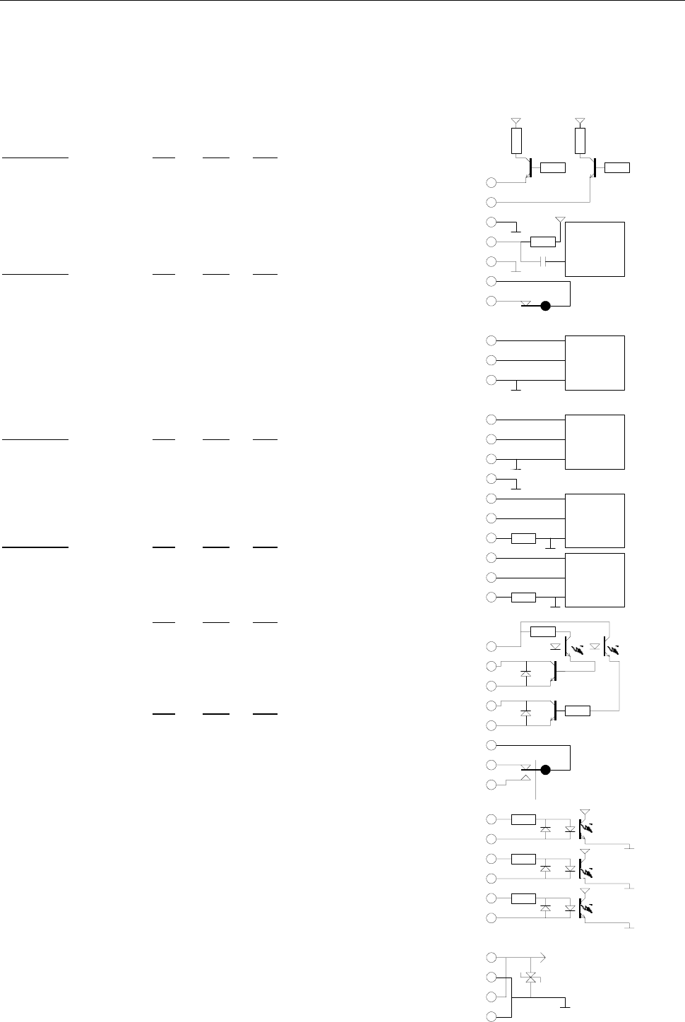
Connection diagram
The electrical interface is shown in the diagram
below. J1, J2 etc. represent different logical (as
well as physical) connectors, which can all be
individually disconnected.
TagMaster AB S1500 / S1501 Reader Data Sheet 2006-06-07
Installation aspects
Microwaves penetrate most non-metallic materials,
such as gypsum, wood, plastics, glass, dirt and
snow. The unit should however if possible be
installed and used so that free space is available
between the ID tag and the reader.
If large reflecting surfaces are present in the
reading zone, the antenna diagram may be
distorted. In such a case, it is recommended to
shorten the distance to the ID tag to achieve a
stronger signal. The system works safely at all
distances down to zero.
If the reader is installed with a low grazing angle to
a reflecting surface such as a road or floor, the
multipath effect can increase the reading distance.
Since the multipath effect may reduce the lobe
width, a test is recommended to check the reader
in such installations, e.g. with the ”Read Beep” test
function available at the control panel.
In the control panel, push the left black button until
”OP” is displayed. Press the right button until ”rb”
is displayed. Press the left button again. In the
read beep operation mode, a short beep is
sounded from the buzzer every time a tag is read,
thus helping to verify the actual reading zone at
installation time.
Restore the reader to normal operation mode by
pressing the right button until ”On” is displayed and
then press the left button.
If several readers are to be operated close to
each other, it is recommended to use different RF
channels to avoid interference. There are 100
channels available.
If tags are passing at a close distance from the
reader it might be a recommendation to reduce
the reading range to avoid unwanted readings of
a remote tag. The range is reduced by setting of
the power and sensitivity parameters.
If the reader is to be used in wet conditions, the
cable inlets should be oriented downwards. It is
recommended to protect the reader from direct
water spray or rain.
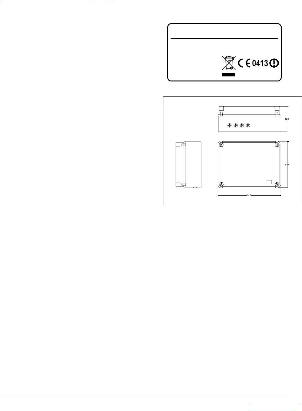
Screened cables shall be used with the screens
clamped according to the figure below.
Note. The DTMF input may be disturbed if the
DTMF cable is exposed to signals in the 1 - 3
MHz region and the prescribed test level (ETS
301 489) for conducted interference is exceeded.
Warning: To comply with the FCC RF
exposure limits, it is recommended that the reader
is installed so that a separation distance of at
least 20 cm (8 inches) from all persons is
provided.
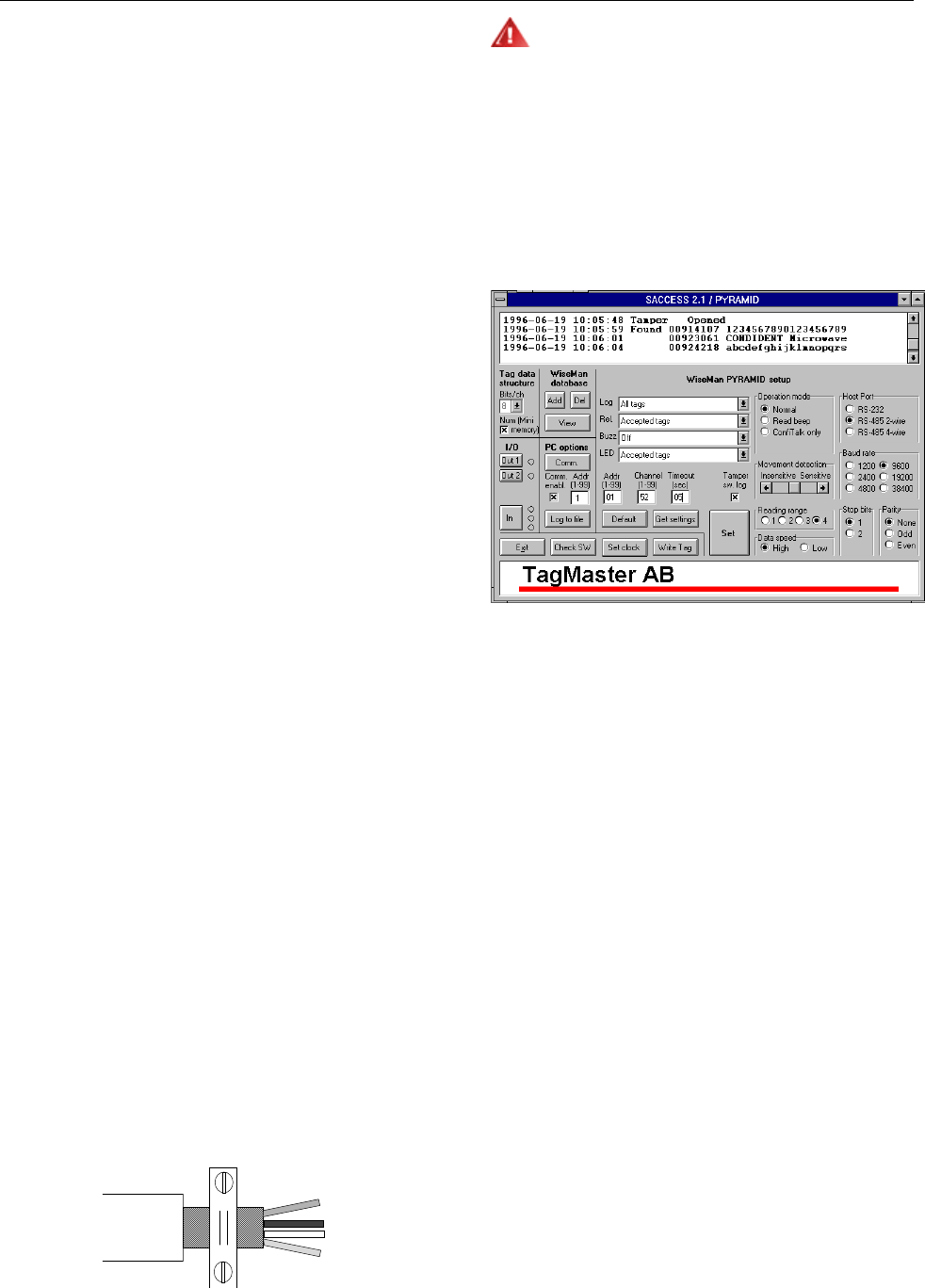
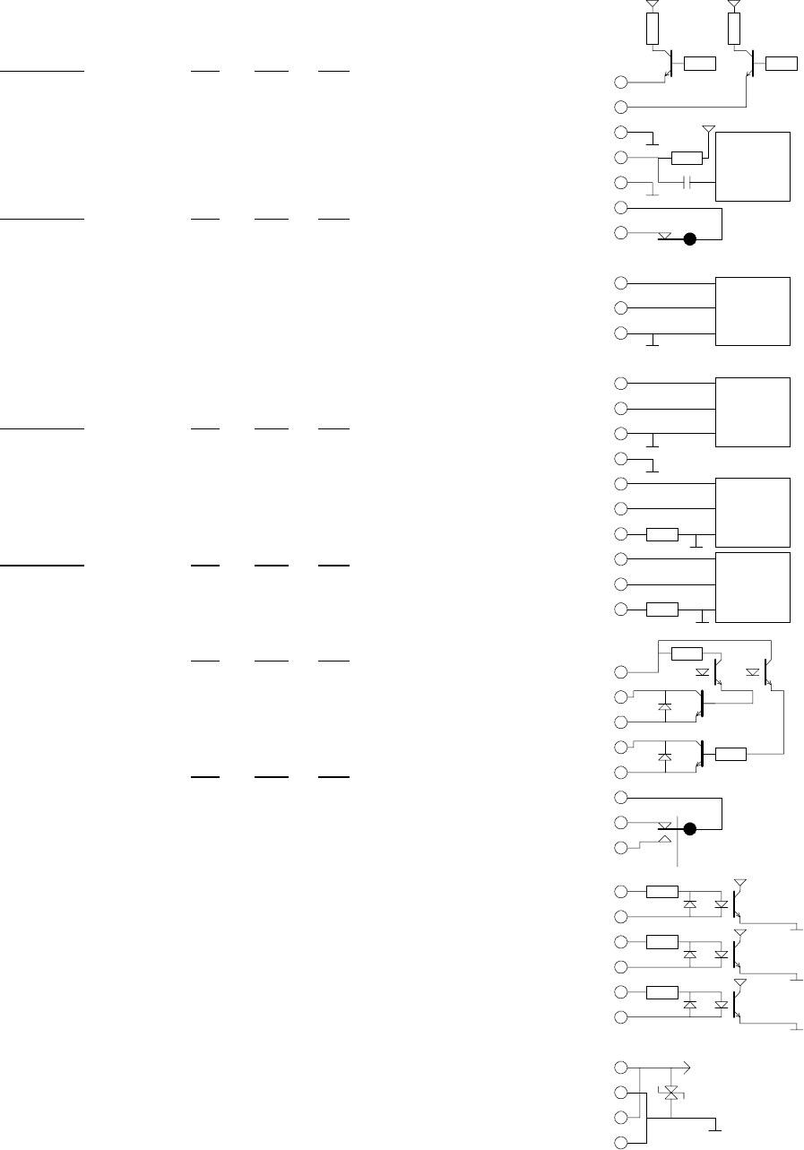
Saccess
To enable a quick start to TAGMASTER, the
SACCESS Windows application is available for
demonstration purposes.
The main functionality is:
• Tag reading
• Tag writing
• Stand alone capability with tag validation and
relay activation
• Database update
• Event and action configuration
• Logging events on screen and file
• Reader serial port and address configuration
S1501 stripped down version
The Reader S1501 is a stripped down version of
the S1500. It is based on the same hardware with
the following differences.
• Application SW: Solid which is used for host
controlled applications.
• 128 Kbyte Flash EEPROM for SW (No
EEPROM database).
• No 7-segment display.
• No buzzer.
• No HW support for 4 wire RS485.
• 12V supply only. Standard voltage regulator
instead of DC/DC converter.
• No real time clock. ConfiLib emulates a real
time clock in software with less accuracy.
TagMaster AB S1500 / S1501 Reader Data Sheet 2006-06-07
S1500/00 Rev 05
TagMaster AB
COMMUNICATOR
FCC ID: M39LRXX
yy
mm nnnnn
DC 24V MAX 1A
Electrical data
Data regards the temperature range -20 to 60 °C.
Parameter Value Unit
DC Supply voltage 20 - 28 V
(selectable by jumper) 10 - 14 V
Consumption 12 V 500 mA
Consumption 24 V 150 mA
Radiation frequency 2435 – 2465 MHz
Output power 10 mW e.i.r.p
Polarisation circular
Tx modulation ASK
Number of RF channels 99
Radiation reduction -12 dB
Sensitivity reduction -24 dB
Reading data speed, high 16 kbit/s
Reading data speed, low 4 kbit/s
Writing data speed 4 kbit/s
Movement det., min speed 0,3 m/s
Movement det., max speed 9,2 m/s
Movement det. max range 5 m
Communication range
data
Reading range typical inst.: 0 to 4 m (13 Ft)
Reading range up to: 6 m (20 Ft)
Writing range : 0 to 0,25 m (0.8
Ft)
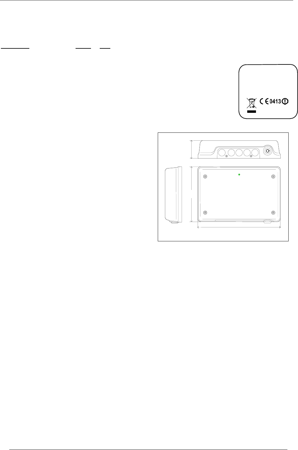
Mechanical data
Product information according to the figure below
is marked on the cover of S1500. A marking
sticker is also placed inside the unit to avoid
mixing up covers and chassis.
Example of marking label:
54 mm
(2,13 In)
263mm (10,35In)
176 mm
(6,93 In)
Weight 1,8 kg
Dimensions (WxLxH): 176 x 263 x 54 mm
Front colour Light grey
Front material Polycarbonate
Back material Stainless steel
Sealing method Rubber gasket
Environmental data
Cold -20ºC (-4ºFh)
IEC68-2-1 Ad
Heat +60ºC(+140ºFh)
IEC68-2-2 Bd
Sealing IP 54
IEC 529
Shock 50 G, 6 ms,
IEC68-2-27 Ea 10x 3 dir
Bump 25 G 6 ms,
IEC68-2-29 Eb 1000x 3 dir
Sine vibration 5G/0,55mm,
IEC68-2-6 Fc 500Hz, 10m,
4 worst freq
Random Vibration
IEC 60068-2-64
Immunity Acc. to CE
leg.
ETSI EN 301 489-3
v1.2.1(0208)
Emission Acc. to CE
leg.
ETSI EN 300 440-1
v1.3.1(0109)
Solar radiation 1120 W/sqm
IEC68-2-5 Sa C 56 days
Safety Electrical and Radio
EN 60950 and EN 60215

TagMaster AB S1500, S1501 Reader Data Sheet Issue 01
10
TagMaster AB Telephone +46 8 632 1950 E-mail support@tagmaster.se
Kronborgsgränd 1 Fax +46 8 750 5362 Website www.tagmaster.com
SE-164 87 KISTA, Sweden
Copyright
The copyright/ownership of this document is and will remain ours. The document must not be used without our authorization or brought to the knowledge of a third party. TagMas-
ter AB.
Disclaimer
The information in this document is subject to change without notice. While the information contained herein is assumed to be accurate, TagMaster AB assumes no responsibility
for any errors or omissions.
S1513/S1514 LR Reader
User programmable Longe
Range Read/Write Station
DATA SHEET
DOC NO. 06-xxx 01
TagMaster AB S1513/S1514 Long Range Reader Data Sheet 2006-06-07
2
Functional description
S1513 Long Range communicator is a 2.45 GHz
circular polarised read/write station for TagMaster
RFID tags. Reading distance is up to 12 meters
(40 Ft). The communicator has 400 RF channels
to eliminate risk for interference of other nearby
communicators. Transmitted power and reception
sensitivity is also adjustable with SW commands
for optimising the installation.
S1513 has a movement detection function for de-
tecting people and vehicles, or even smaller ob-
jects, even if not using a tag. It can determine
their moving speed in approaching or retreating
directions.
S1513 is user programmable and has a large
memory for application programs and built in da-
tabase functions for fast, customised and efficient
stand-alone operation. User software is
downloaded and saved in EEPROM through a
serial communication line. If user programming is
not required, there is a ready-to-use standard
application SW in the communicator.
A local database in EEPROM can be loaded with
over 15,000 tag entries for extremely fast read-
validate-activate response times.
The ConfiTalk protocol is used for serial commu-
nication in a polled RS485 network or point-to-
point in RS232 connections. There are ConfiTalk
communication drivers available for Microsoft
Windows for PC with interface for C/C++, Delphi
and Visual Basic.
S1513 has two serial ports, a DTMF port for key-
pads, LED interfaces, relay, parallel I/O (emulat-
ing magcard data as an option).
In S1513 a control panel with a 7-segment LED
display, two push buttons, a three colour LED, a
buzzer and a reset button is available for local
configuration and start up of test programs as in-
stallation aids. The unit can also be configured
using a hand held computer or terminal con-
nected locally.
S1513 is sealed from water spray and dust. Non
corrosive materials are used in external parts.
Connections are made through rubber bushings,
or via cable glands. Jackable screw connectors
connect the wires. Built in DC/DC converters tol-
erate noisy voltages, provide low power con-
sumption (3W) and accept 24 as well as 12 VDC
Microwave/Antenna block
Processor block
I/O block
DC supply
RS 485
RS 232a
RS 232b
DTMF/LED
Relay
Opto I/O
Radiated 2.45 GHz signal
8 m (26.25 Ft) reading range
Range/channel setting by SW
Tag programming
Movement detection at up to 5 m
(16.4 Ft)
3-colour LED and buzzer
RS232 and 2/4 wire RS485
3 parallel in, 2 parallel out
Relay and tamper switches
EMI tolerant DC/DC conv.
24V or 12V powering
User programmable
C, Delphi and VB drivers
Flash EEPROM database
DTMF and LED interface
Maintenance functions
TagMaster AB S1513/S1514 Long Range Reader Data Sheet 2006-06-07
3
General
S1513 comprises a plastic cover and within a
metal chassis for two PC boards, where the
upper position carries a standard board and
the lower is for an option board. A rubber gas-
ket seals the unit.
The standard board includes a Processor and
I/O block with analog and digital circuits, and
is integrated with a Microwave and Antenna
block.
The antenna system is circular polarised and
radiates through the front cover, with a lobe
that is directed perpendicularly to the front
surface of S1513. The lobe shape can be de-
scribed as an ellipsoid with a circular cross
section, as shown in the figure below.
The reading and writing distances depend on
the tag type and on the power and sensitivity
SW settings. Typically, S1513 can read Tag-
Master tags at up to 12 m (39 Ft) distance.
See Reading/Writing range for reference.
When dismounting the cover, it separates
from the cable inlets to conveniently operate
the unit also without cover. Screw connectors
are jackable and in logical groups, i.e. it is not
needed to disconnect each wire to replace the
electronics.
J1 DTMF, LED, external tamper line
J2 RS232 for terminal
J3 RS232 and RS 485 for host
J4 Parallel out and relay
J5 Parallel in
J6 DC supply
Dual tamper switches monitor that the cover is
closed. When removed, a software as well as
hardware alarm is generated.
For service and setup purposes there is a
control panel with a 7-segment LED display, 2
control buttons, a reset button, a LED and a
buzzer. There are also jumpers for RS232/485
and 12/24V selection.
TagMaster AB S1500 / S1501 Reader Data Sheet Issue 01
Copyright
The copyright/ownership of this document is and will remain ours. The document must not be used without our authorization or brought to the knowledge of a third party. TagMaster AB.
Disclaimer
The information in this document is subject to change without notice. While the information contained herein is assumed to be accurate, TagMaster AB assumes no responsibility for any errors or
omissions.
Reading/writing range
The maximum reading or writing range is defined
as the maximum distance along the radiation axis
where the tag can be communicated when the tag
and communicator face each other and when
there is free space in between.
The free space reading range for S1513 is up to
more than 12 m (39 Ft).
In a typical installation the reading range is up to 8
m (26 Ft)
Writing range is up to 1.2 m (4 Ft)
The reading range depends on the tag reflectivity,
the data speed (high/low), power output and sen-
sitivity settings.
If using low power and/or low sensitivity the read-
ing range is reduced according to the following
table.
Range Sensitivity Power Range factor
4 HIGH HIGH 100%
3 HIGH LOW 50%
2 LOW HIGH 25%
1 LOW LOW 12%
Writing must be done at high power. The writing
range is normally not affected by speed and sen-
sitivity settings.
Lobe width
The lobe diagram shows, in a proportional scale,
the approximate lobe shapes of the S1513 and
S1514 readers.
Curves 4, 3, 2 and 1 show areas for safe reading
for the four different combinations of power and
sensitivity.
Example: Your reading range has been calculated
to 8.0 meters, meaning each square in the dia-
gram is 8.0/10=0.8 meters. The lobe width at 70%
range is then 5.5 squares * 0.8 = 4.4 meters.
The diagram concerns a free space installation,
and does not take into account possible influ-
ences from signal reflections or attenuating struc-
tures.
For reliability reasons, it is recommended that
tags are passing at 70 % or less of maximum
reading and writing range.
Reading/writing time
The time for reading and writing tags are specified
in the tag data sheets. Please refer to the data
sheet of the specific tag concerned.
Passage speed
The table shows the maximum allowed passage
speed in km/h for combinations of tag reading
time and lobe widths.
Lobe width [m]
Reading time [ms] 1 1.5 2.0 2.5 3.0
20 180 270 360 450 540
50 72 108 144 180 216
70 51 77 103 129 154
100 36 54 72 90 108
130 28 42 56 69 83
150 24 36 48 60 72
200 18 27 36 45 54
Tag orientation
Thanks to the circular polarisation, the reading
and writing ranges are independent from the rota-
tional orientation around the radiation axis. How-
ever, if the ID tag is very tilted in relation to the
communicator, a range reduction may occur.
Since this effect depends mainly on the specific
installation, it is recommended that a test is made.
S1513 can be set to a "read beep" mode to con-
veniently check out the reading range.
Movement detection
S1513 detects a moving person or car at up to 10
m (33 Ft) distance, even when moving slowly. The
communicator senses if the object is approaching
or moving away from the communicator, and at
5
what radial speed. The detection threshold can be
set to different sensitivity levels.
6
Software
The communicators are delivered with the pre-
installed software Pyramid for standard applica-
tions. However, you can easily develop your own
application software to be executed inside the
communicator. This will give you the full power of
controlling the communicator operation for flexi-
ble solutions and fast response times.
User application development
For user application development there are com-
plete software development kits (SDK) including
compilers, loaders, tools, drivers and libraries
supporting the complete development phase for
communicator applications as well as PC applica-
tions.
ConfiLib
ConfiLib
DLL
User or standard
application
Delphi
Visual
Basic
C/C++
User
applications
PC Communicator
ConfiTalk
RS232
RS485
Communicator applications are developed in a PC
environment with the cross compiler ConfiComp
and can be executed in the PC for testing and de-
bugging. The complete software is finally
downloaded, using ConfiLoad, to the communica-
tor for permanent storage in EEPROM. PC appli-
cations are developed with any PC software de-
velopment tool. For application programmers a
ConfiTalk Commander is available for training and
low level communications management.
ConfiLib
ConfiLib is a function library with hundreds of
functions for communicator management and
ConfiTalk protocol handling. ConfiLib exist in ver-
sions both for communicators and Microsoft Win-
dows for PC.
The communicator version of ConfiLib is a func-
tion library package in C language. For PC envi-
ronments, the ConfiLib API comes as dynamic
link libraries (DLL) with C/C++ interface. There
are also separate interface modules for Visual
Basic and Delphi available. Typical functions in-
clude read/write/format tags, read/write/search
database, HW/SW configuration, read/write I/O,
ConfiTalk send/receive, timers, buffers, mail man-
agement, etc.
ConfiTalk
ConfiTalk is the standard serial communications
protocol used by the communicators. The protocol
transfers data to and from a communicator and
handles flow control, retransmissions, checksums
and data transparency. It can be used both for
point-to-point and multidrop networks, using a
polling procedure.
ConfiTalk can also be replaced by a user defined
protocol.
Pyramid application
Pyramid application operates stand-alone reading
tags, validating according to a downloaded data-
base white list, activating relays for valid tags and
producing logs for a PC to collect on- or off-line.
Pyramid can also sense movements of people
and vehicles using the movement detection.
Events
Following events may trig actions:
• A tag is read
• A tag is read and found in the database (vali-
dated)
• A movement is detected
Actions
For each event following actions may be speci-
fied:
• The event is logged
• The relay is pulled
• The buzzer is turned on
• The LED is set to different colours
Alarms
Following alarms can be generated:
• Tamper switch alarm
• Reset alarm
Database
The database in S1513 stores more than 15.000
tag identities.
Movement detection
When enabled, this feature can sense movements
5 meters (16.39 Ft) away or at reduced ranges.
Timer
Relay activation time and tag timeout can be set.
Logging
All events and alarms are logged to be retrieved
by a PC on- or off-line. Log size is 250-1000
events.
Terminal
For serial port configuration and local operating at
installation time, an optional terminal can be con-
nected to the terminal interface Check SW.
Pyramid may also be set to Off mode without any
stand-alone operation. Instead, all ConfiLib com-
mands are available on the serial port interface for
a PC controller.

7
Control panel setup
Under the cover of the S1513 there is a control
panel available for local configuration and opera-
tion without the need of a terminal or PC.
The left black button is used for parameter selec-
tion and the right black button is used for value
selection.
Example to change the ConfiTalk address: Push
the left button repeatedly until ‘Ad’ is displayed.
Push the right button to display the current ad-
dress. Repeat pushing the right button until the
wanted address is displayed. Press the left button
to save the configuration. When there are
unsaved changes, the LED is red.
The configuration is stored in non-volatile mem-
ory, and is retained after a power failure.
To reset the communicator to default configura-
tion and erase the database, keep the two black
buttons pushed while pressing the red reset but-
ton. Release the buttons when the LED blinks yel-
low. Push the red button again.
To invoke the terminal interface Check SW in
S1513, keep one of the two black buttons pushed
while pressing the red button.
Hardware
Processor block
The processor block includes a 16 bit microproc-
essor, 384 kByte Flash EEPROM, 100 byte
EEPROM, 128 kByte SRAM and a bus interface
for an external option board. Option boards are
inserted in the lower position slot.
Flash EEPROM is used for program code and da-
tabases while the small EEPROM may be used
for configuration data. This information is retained
even after DC power interruption for any period of
time. Programs and configuration can therefore
be downloaded at production time and remains
unchanged even after transportation.
The SRAM memory is used for program data, tag
reading logs, communication mail messages, etc.
The processor block includes a real time clock
(RTC) and a watchdog for automatic restart in
case of software failure.
A rechargeable backup battery for SRAM and
RTC is automatically charged as soon as the unit
is under voltage, and retains its voltage during two
weeks after loss of power provided that the bat-
tery jumper is in the on position.
Jumper settings
There are jumpers for selecting if the second se-
rial port should be RS232 or RS485 and if the
RAM backup battery shall be connected. See fig-
ure below.
Host RS232 (Tx)
Host RS232 (Rx)
Host RS485 (Tx)
Host RS485 (Rx)
Battery on Battery off
Under the rightmost antenna, additional jumpers
are available for setting the unit to 12 or 24 volt
operation. Markings on the PC board indicate how
to set these jumpers. The factory setting is 24 V.
8
Hardware interface
The I/O block comprise the following interface.
DTMF
2-wire interface to receive a dual tone signal and
to power a DTMF device.
Parameter Min Max Unit
Line volt. @ 10 mA 4.1 4.5 V
Tone level -26 0 dBm
RS 232 - host and terminal
Default: 9600 bps, 8 bits, no parity, 1 stop bit,
ConfiTalk address 1
Parameter Min Max Unit
Baud rate 1.2 19.2 kbits/s
Data bits 7 8 bits
Stop bits 1 2 bits
Parity no - odd - even
RS 485 - host
Full (4 wire) or half duplex (2 wire). Default: 9600
bps, 8 bits, no parity, 1 stop bit, ConfiTalk address
1
Parameter Min Max Unit
Baud rate 1.2 38.4 kbits/s
Data bits 7 8 bits
Stop bits 1 2 bits
Parity no - odd - even
Optocoupler inputs
Parameter Min Max Unit
High voltage 2,4 30 V
Low voltage 0.0 0.2 V
Open collector outputs
Parameter Min Max Unit
Allowed voltage 1 30 V
Sink current Out 1 0 500 mA
Sink current Out 2 0 100 mA
Relay
Parameter Min Max Unit
Switch current 2 A
Switch voltage DC 220 V
Switch voltage AC 125 V
Switch power 50 W
Connection diagram
The electrical interface is shown in the diagram
below. J1, J2 etc. represent different logical (as
well as physical) connectors, which can all be in-
dividually disconnected.
Rtnspl 1
Rtnspl 2
Spl 1
Spl 2
Gnd485r
Gnd485t
Tx+/Rx+485
Tx-/Rx-485
Gnd 232b
Rx232b
Tx232b
Standard IC
Standard IC
Standard IC
CGnd
Gnd 232a
Rx232a
Tx232a
Standard IC
Tamp b
Tamp a
RtnDTMF
SDTMF
GndLED
LED 2
LED
1
DTMF
470 470
100
receiver
100
100
J1: 1
2
3
4
5
6
7
J2: 1
2
3
J3: 1
2
3
4
5
6
7
8
9
10
In 3c
In 3a
In 2c
In 2a
In 1c
In 1a
2,2 k
2,2 k
2,2 k
J
5: 1
2
3
4
5
6
R1m
R1b
R1c
Out 2e
Out 2c
Out 1e
Out 1c
Outspl1
J
4: 1
2
3
4
5
6
7
8
J
6: 1
2
3
4
Cover on
DC/DC converter
or linear regulator
Rx485-
Rx485+
9
Installation aspects
Microwaves penetrate most non metallic materials,
such as gypsum, wood, plastics, glass, dirt and
snow. The unit should however if possible be in-
stalled and used so that free space is available be-
tween the ID tag and the communicator.
If large reflecting surfaces are present in the read-
ing zone, the antenna diagram may be distorted. In
such a case, it is recommended to shorten the dis-
tance to the ID tag to achieve a stronger signal.
The system works safely at all distances down to
zero.
If the communicator is installed with a low grazing
angle to a reflecting surface such as a road or
floor, the multipath effect can increase the reading
distance. Since the multipath effect may reduce
the lobe width, a test is recommended to check the
communication in such installations, e.g. with the
”Read Beep” test function available at the control
panel.
In the control panel, push the left black button until
”OP” is displayed. Press the right button until ”rb”
is displayed. Press the left button again. In the
read beep operation mode, a short beep is
sounded from the buzzer every time a tag is read,
thus helping to verify the actual reading zone at
installation time.
Restore the communicator to normal operation
mode by pressing the right button until ”On” is dis-
played and then press the left button.
If several communicators are to be operated close
to each other, it is recommended to use different
RF channels to avoid interference. There are 100
channels available.
If tags are passing at a close distance from the
communicator it might be a recommendation to
reduce the reading range to avoid unwanted read-
ings of a remote tag. The range is reduced by set-
ting of the power and sensitivity parameters.
If the communicator is to be used in wet condi-
tions, the cable inlets should be oriented down-
wards. It is recommended to protect the commu-
nicator from direct water spray or rain.
Screened cables shall be used with the screens
clamped according to the figure below.
Note. The DTMF input may be disturbed if the
DTMF cable is exposed to signals in the 1 - 3
MHz region and the prescribed test level (ETS
300 683) for conducted interference is exceeded.
Warning: To comply with the FCC RF expo-
sure limits, it is recommended that the reader is
installed so that a separation distance of at least
20 cm (8 inches) from all persons is provided.
Saccess
To enable a quick start to TagMaster products,
the SACCESS Windows application is available
for demonstration purposes.
The main functionality is:
• Tag reading
• Tag writing
• Stand alone capability with tag validation and
relay activation
• Database update
• Event and action configuration
• Logging events on screen and file
• Communicator serial port and address configu-
ration
S1514 stripped down version
The Reader S1514 is a stripped down version of
the S1513. It is based on the same hardware with
the following differences.
• Application SW: Solid which is used for host
controlled applications.
• 128 Kbyte Flash EEPROM for SW (No
EEPROM database).
• No 7-segment display.
• No buzzer.
• No HW support for 4 wire RS485.
• 12V supply only. Standard voltage regulator
instead of DC/DC converter.
• No real time clock. ConfiLib emulates a real
time clock in software with less accuracy.
10
S1503/00
TagMaster AB
Communicator
Revision 05
FCC ID: M39LRXX
yymmnnnnn DC 24V MAX 1A
Electrical data
Data regards the temperature range -20 to 60 °C.
Parameter Value Unit
DC Supply voltage 20 - 28 V
(selectable by jumper) 10 - 14 V
Consumption 12 V 500 mA
Consumption 24 V 150 mA
Radiation frequency 2435 – 2465 MHz
Output power 10 mW e.i.r.p
Polarisation circular
Tx modulation ASK
Number of RF channels 99
Radiation reduction -12 dB
Sensitivity reduction -24 dB
Reading data speed, high 16 kbit/s
Reading data speed, low 4 kbit/s
Writing data speed 4 kbit/s
Movement det., min speed 0,3 m/s
Movement det., max speed 9,2 m/s
Movement det. max range 5 m
Communication range
data
Reading range typical inst.: 0 to 4 m (13 Ft)
Reading range up to: 6 m (20 Ft)
Writing range : 0 to 0,25 m (0.8
Ft)
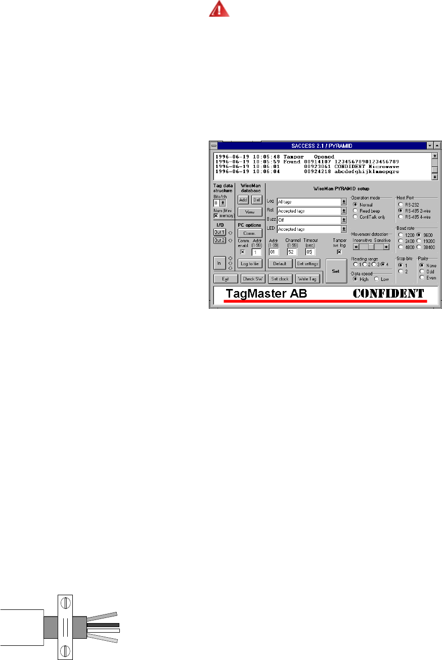
Mechanical data
Product information according to the figure below
is marked on the cover of S1500. A marking
sticker is also placed inside the unit to avoid mix-
ing up covers and chassis.
Example of marking label:
Weight 1,8 kg
Dimensions (WxLxH): 315 x 234 x 128 mm
Front colour Light grey
Front material Polycarbonate
Back material Stainless steel
Sealing method Rubber gasket
Environmental data
Cold -20ºC (-4ºFh)
IEC68-2-1 Ad
Heat
+60ºC(+140ºFh)
IEC68-2-2 Bd
Sealing IP 54
IEC 529
Shock 50 G, 6 ms,
IEC68-2-27 Ea 10x 3 dir
Bump 25 G 6 ms,
IEC68-2-29 Eb 1000x 3 dir
Sine vibration 5G/0,55mm,
IEC68-2-6 Fc 500Hz, 10m,
4 worst freq
Random Vibration
IEC 60068-2-64
Immunity Acc. to CE
leg.
ETSI EN 301 489-3
v1.2.1(0208)
Emission Acc. to CE
leg.
ETSI EN 300 440-1
v1.3.1(0109)
Solar radiation 1120 W/sqm
IEC68-2-5 Sa C 56 days
Safety Electrical and Radio
EN 60950 and EN 60215
TagMaster AB Telephone +46 8 632 1950 E-mail support@tagmaster.se
Kronborgsgränd 1 Fax +46 8 750 5362 Website www.tagmaster.com
11
SE-164 87 KISTA, Sweden
Copyright
The copyright/ownership of this document is and will remain ours. The document must not be used without our authorization or brought to the knowledge of a third party. TagMaster AB.
Disclaimer
The information in this document is subject to change without notice. While the information contained herein is assumed to be accurate, TagMaster AB assumes no responsibility for any errors
or omissions.
S1566 Heavy Duty Reader
DATA SHEET
DOC NO. xxx
Special features
• Long read-range, up to 6m (20ft)
• Extremely tolerant to high
electromagnetic fields
• Complying with railway standards
• Specially designed for tough demanding
environments
• 2.45 GHz licence free band
• Easy integration with controlling system
• User-programmable for adaptation or
standalone-operation
• High passage speed, up to 400 km/h
TagMaster AB S1566 HD Reader Data Sheet 2006-06-07
2
General
The Heavy Duty Reader S1566 is a read/write
unit intended for RFID applications with very
high requirements on electrical and
mechanical endurance.
The unit is designed to withstand railway
requirements, being vehicle mounted in high
power electromagnetic field.
Mounting on underground train close to the
power pick-up rail is an example where the
S1566 is the ultimate choice.
S1566 is a microwave based read/write
heavy-duty station for RFID operating in the
2.45 GHz band which is possible to use all
over the world.
It communicates with ID-tags through
antennas and communicates with host via
standard interfaces.
It is designed according to existing regulations
for RFID equipment and railway standards.
The reader is capable of reading TagMaster ID-
tags at a distance up to 6 m. The receiver
circuitry uses digital processing techniques,
which enables use in high-speed applications,
such as for train or other vehicle identification, up
to 400 km/h.
The unit is DC powered from an external source.
The design is made for installation in harsh
environments and its construction protects it
from water spray, dust and other environmental
conditions.
The Reader has a high performance
synthesized frequency generator and a selective
receiver. Tx/Rx parameters such as frequency,
output power and sensitivity are software
controlled, and the reception circuitry uses
digital processing techniques.
The Heavy Duty Reader S1566 operates at the
2.45 GHz ISM frequency band (Industrial,
Scientific and Medical). This is widely used over
the world without license requirement. On this
high frequency (2.45 GHz) the communication is
not affected by ignition and other electromagnetic
disturbances that are generated from engines or
electric equipment.
TagMaster AB S1566 HD Reader Data Sheet 2006-06-07
3
Reading/writing
range
The maximum reading or writing range is
defined as the maximum distance along the
radiation axis where the tag can be
communicated when the tag and reader face
each other and when there is free space in
between.
The free space reading range for S1566 is up
to more than 6 m (20 Ft).
In a typical installation the reading range is up
to 4m (13 Ft)
Writing range is up to 0.25 m (0.8 Ft)
The reading range depends on the tag
reflectivity, the data speed (high/low), power
output and sensitivity settings.
If using low power and/or low sensitivity the
reading range is reduced according to the
following table.
Range Sensitivity Power Range factor
4 HIGH HIGH 100%
3 HIGH LOW 50%
2 LOW HIGH 25%
1 LOW LOW 12%
Writing must be done at high power. The
writing range is normally not affected by speed
and sensitivity settings.
Lobe width
The lobe diagram shows, in a proportional
scale, the approximate lobe shapes of the
S1566 readers.
Curves 4, 3, 2 and 1 show areas for safe
reading for the four different combinations of
power and sensitivity.
Example: Your reading range has been
calculated to 4.0 meters, meaning each square
in the diagram is 4.0/10=0.4 meters. The lobe
width at 70% range is then 5.5 squares * 0.4 =
2.2 meters.
The diagram concerns a free space
installation, and does not take into account
possible influences from signal reflections or
attenuating structures.
For reliability reasons, it is recommended that
tags are passing at 70 % or less of specified
reading and writing range.
Reading/writing time
The time for reading and writing tags are
specified in the tag data sheets. Please refer to
the data sheet of the specific tag concerned.
Passage speed
The table shows the maximum allowed
passage speed in km/h for combinations of tag
reading time and lobe widths.
Lobe width [m]
Reading time
[ms]
1 1.5 2.0 2.5 3.0
20 180 270 360 450 540
50 72 108 144 180 216
70 51 77 103 129 154
100 36 54 72 90 108
130 28 42 56 69 83
150 24 36 48 60 72
200 18 27 36 45 54
Tag orientation
Thanks to the circular polarisation, the reading
and writing ranges are independent from the
rotational orientation around the radiation axis.
The reading time for the tag, can be found in
the tag datasheets. If the ID tag is very tilted in
relation to the reader, a range reduction may
occur. Since this effect depends mainly on the
specific installation, it is recommended that a
test is made.
TagMaster AB S1566 HD Reader Data Sheet 2006-06-07
4
Software
The readers are delivered with the pre-
installed TagMaster software Solid software for
standard applications. Should the option real-
time clock, built-in database or I/O be selected,
the reader can be pre-installed with TagMaster
Pyramid software. The software platform in the
reader allows the user to develop their own
application software However, you can
develop your own application software which
can be downloaded and to be executed inside
the reader. This will give youwill give the user
the full power control overof controlling the
reader’s operation for flexible solutions and
fast response times.
User application development
For user application development there is a
complete software development kits (SDK)
including compilers, loaders, tools, drivers and
libraries supporting the complete development
phase for reader applications as well as PC
applications.
Reader applications are developed in a PC
and the complete software is downloaded,
using ConfiLoad, to the reader for permanent
storage in EEPROM. PC applications are
developed with any PC software development
tool. For application programmers a ConfiTalk
Commander is available for training and low
level communications management.
ConfiLoad
ConfiLoad is Windows software that
“downloads” a reader application to the reader
over standard RS232. This provides the
possibility to easily upgrade readers without
replacing the EEPROM.
ConfiLib
ConfiLib is a function library with hundreds of
functions for reader management and
ConfiTalk protocol handling. ConfiLib exists in
versions both for readers and PC
environments including DOS, Windows 3.1,
95/98/ME and NT/2000/XP. The reader
version of ConfiLib is a function library
package in C language. For PC environments,
the ConfiLib API comes as dynamic link
libraries (DLL) with C/C++ interface. There are
also separate interface modules for Visual
Basic and Delphi available.
ConfiTalk
ConfiTalk is the standard serial
communications protocol used by the readers.
The protocol transfers data to and from a
reader and handles flow control,
retransmissions, checksums and data
transparency. It can be used both for point-to-
point and multidrop networks, using a polling
procedure.
TagMaster AB S1566 HD Reader Data Sheet 2006-06-07
5
Communication
interface
RS 485 Interface
The RS 485 interface is compatible with the
RS 485 standard. This interface is normally
connected to a host computer.
Configuration parameters for the RS 485
interface are controlled by software. The
following settings are possible (bold settings
are default):
Baud rate 150 - 9600 - 38400 *
Data bits 7 or 8
Parity Odd, even or No parity
Stop bits 1 or 2
The communication is in half (2-wire) duplex. A
shielded data cable shall be used with twisted
pairs with the following characteristics:
Impedance 120 ohm
Capacitance (max) 66 pF/m
Resistivity (max) 80 ohm/m
RS 232 Interface
The RS 232 interface is compatible with the
RS 232 standard. This interface is normally
used as a service interface.
Configuration parameters for the RS 232
interface are controlled by software. The
following settings are possible (bold settings
are default):
Baud rate 150 - 9600 - 38400 *
Data bits 7 or 8
Parity Odd, even or No parity
Stop bits 1 or 2
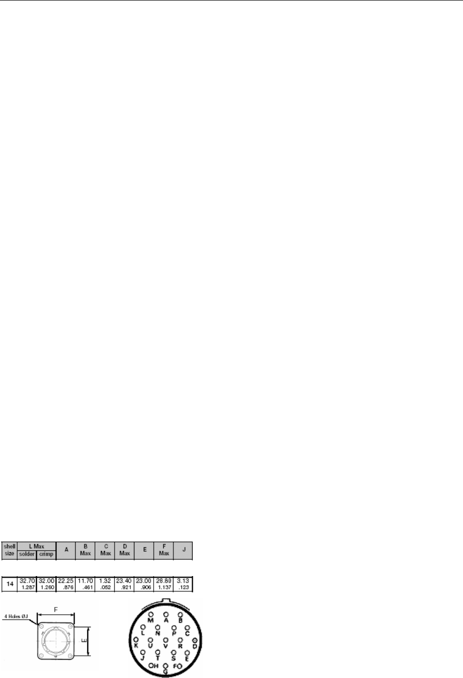
Connector
The readers means of connection to the host
system is via a 19-pole jackable size 14
military type connector (FCI / Souriau part no:
FCI-851 02R 14-19 S50) selected to make a
connection unexposed to dust, wet and
insensitive to vibrations.
Pin configuration
Power Supply
Connector
PIN P DC power. (12 V or 24 V)
PIN R DC power. (0 V)
DC Ground (via a “Y” capacitor and a resistor
to casing)

TagMaster AB S1566 HD Reader Data Sheet 2006-06-07
6
Pin configuration
Power Supply
Connector
PIN P DC power. (12 V)
PIN R DC power. (0 V)
DC Ground (via a “Y” capacitor and a resistor
to casing)
RS232 communication port A
Connector
PIN A Tx/232A.
PIN B Rx/232A.
PIN C GND/232A
RS485 communication port B
Connector
PIN H Tx+/Rx-485: Transmit (and
receive when 2-wire is used),
low wire.
PIN J Tx-/Rx+485: Transmit (and
receive when 2-wire is used),
high wire.
PIN K Gnd485: Shield ground for
transmits wires. Note: Signal
ground, Interface ground are
separated from chassis.
Alternative RS232 communication port B
Connector
PIN H Tx/232B
PIN J Rx/232B
PIN K GND/232B
TagMaster AB S1566 HD Reader Data Sheet 2006-06-07
7
Electrical data
Data regards the temperature range -20 to 60
°C.
Parameter Value Unit
DC Supply voltage 10-14 V
(available as option) 20 - 28 V
Consumption 12 V 500 mA
Consumption 24 V 150 mA
Radiation frequency 2435 – 2465 MHz
Output power 10 mW e.i.r.p
Polarisation circular
Tx modulation ASK
Number of RF channels 99
Radiation reduction -12 dB
Sensitivity reduction -24 dB
Reading data speed, high 16 kbit/s
Reading data speed, low 4 kbit/s
Writing data speed 4 kbit/s
Mechanical Data
Weight: 3600 grams
Casing: Aluminium
Antenna cover: Polycarbonate Fire class V-2
(UL 94); Halogen free.
Colour: Black with grey cover over
antennas
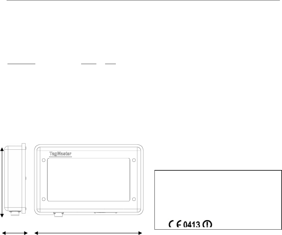
Dimensions:
L x W x H: 310 x 200 x 61 mm.
Marking: The Reader is marked with a label.
Example of label specifying:
Mounting
The unit is intended for front mounting using a
mounting bracket. There is a special mounting
fixture for mounting on each train type.
Suitable screw dimensions: M8x16. The reader
has 4 mounting holes on the front face.
Manufacturer TagMaster AB
Type S1566 rev 05
Serial number year – week – nr -----
FCC ID M39LRXX
Power supply rating 12V 24V DC, 500 150
mA
0413
310mm
200mm
61mm

TagMaster AB S1566 HD Reader Data Sheet Issue 03
TagMaster AB Telephone +46 8 632 1950 E-mail support@tagmaster.se
Kronborgsgränd 1 Fax +46 8 750 5362 Website www.tagmaster.com
SE-164 87 KISTA, Sweden
8
Climatic
Temperature -25°C..+ 60°C
Protection class IP 65
Damp heat cyclic IEC68-2-30 : 1983
Change of temperature IEC 60068-2-14
Mechanical
Bump IEC 68-2-29 Eb
15g 6ms, 2x1000 bumpbs per 3 axis
Shock IEC 68-2-27 EA
Orientation Peak acceleration Nominal
duration
A m/s2 D ms
Vertical 30 30
Transverse 30 30
Longitudinal 50 30
3+ 3 shocks per 3 axis
Random Vibration IEC 68-2-34 Fd
RIA20 Freq span 5-150 Hz (table 2)
Orientation RMS m/s2 Frequency range
Vertical 1.00 2
Transverse 0,45 2
Longitudinal 0,70 2
Simulated Long Life BRB/LUL/RIA
Specification no.20
Random vibration 5 hours each direction axis x 3
Orientation RMS 5 hrs
test period m/s2 Frequency range
Vertical 7,90 2
Transverse 3,50 2
Longitudinal 5,50 2
Electrical
EMC 301 489-3:2000
Railway applications EMC DD ENV 50121-4 1996
El. Safety EN 60 950
Health 1999/519/EC
Radio EN 300 440:2001
Supply related surge BRB/RIA12
Variation of voltage supply DD ENV 50121-3-2
(1996)
EN 50155
Indirect Transient BRB/RIA 12 EN50155
Radio RFI susceptibility RIA 18DD ENV 50 121-
3-2 1996,
EN 50155:1995,
EN 301 489-3, EN 50
204
Radio frequency emission RIA 18, EN 50155:1995
DD ENV 50121-3-2
ETS 300 827,EN 300
440V 1.2.1
Conducted emission DD ENV 50121-3-2:
1996
ETS 300 827, EN 301
489-3
Transient immunity DD ENV 50121-3-2:
1996
Surges DD ENV 50121-3-2:
1996
Conducted radio frequency DD ENV 50121-3-2:1996
ESD DD ENV 50121-3-2
(1996),
EN 301 489-3
E.I.R.P EN 300 440V 1.2.1
Frequency range EN 300 440V 1.2.1
Surges and burst EN 301 489-1 V1.4.1
S1566 complies with EC directives for EMC;
89/336/EEC (with additional directive 92/31/EEC)
R&TTE directive 1999/5/EC
Reliability
The expected MTBF is 1 000 000 hours for stationary
a
pp
lications and 150 000 hours for mobile a
pp
lications.
Environmental data
Warning: To comply with the FCC RF exposure limits, it is recommended that the reader is installed so
that a separation distance of at least 20 cm (8 inches) from all persons is provided.

TagMaster AB S1566 HD Reader Data Sheet Issue 02
9