Tagmaster LRXX RFID Communicator User Manual DS S1500
Tagmaster AB RFID Communicator DS S1500
UserManual.wiki
>
Tagmaster
>
LRXX User Manual
>
Data sheets
Contents
1.
Installation guide
2.
Data sheets
3.
Installation manual
4.
User manual
Data sheets
Navigation menu
Upload a User Manual
Namespaces
Wiki Guide
HTML
PDF
Info
Views
User Manual
Discussion / Help
Navigation
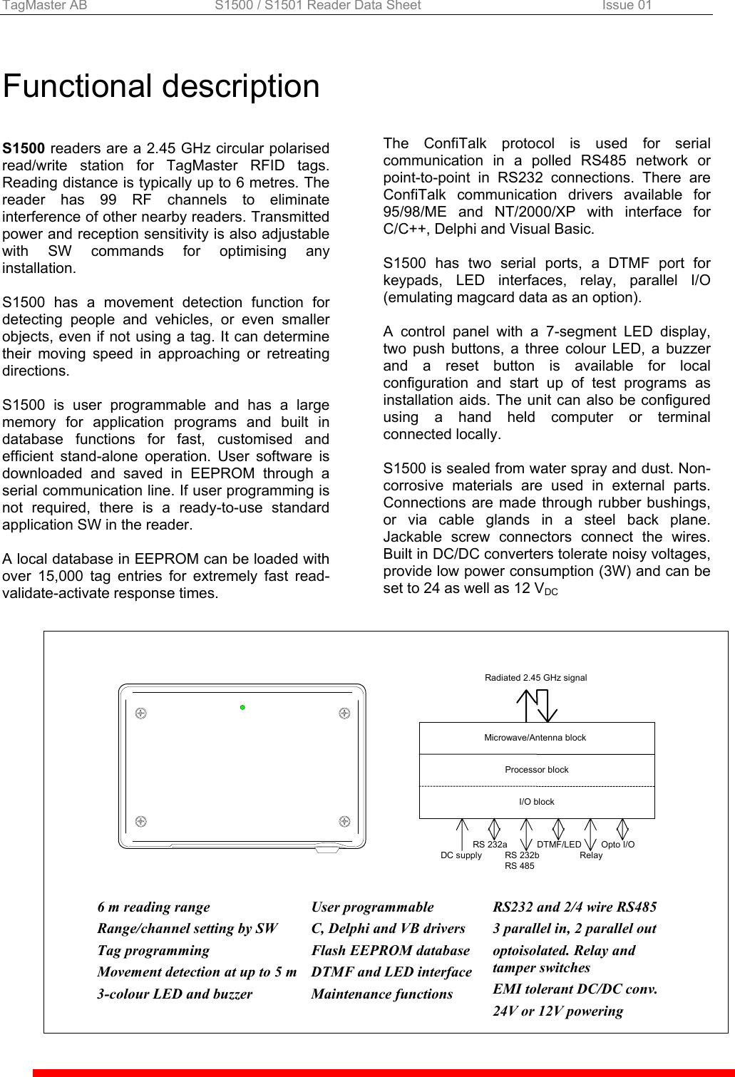
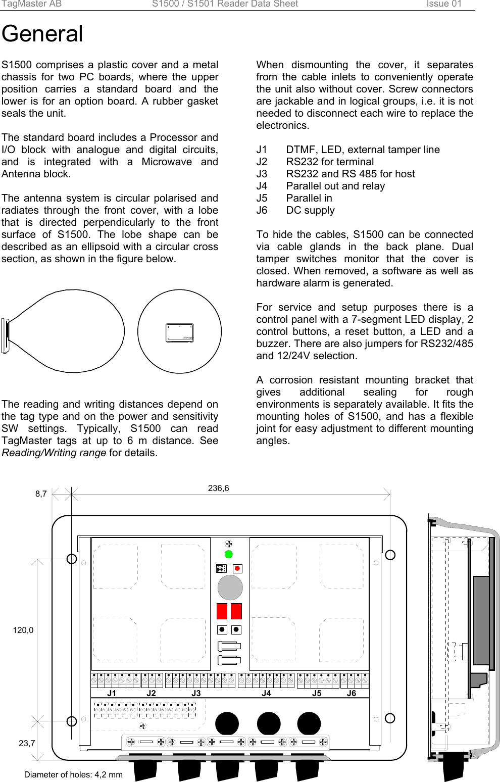
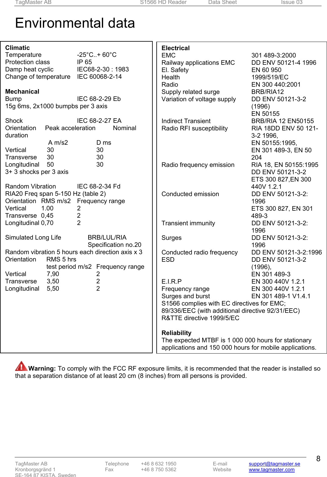
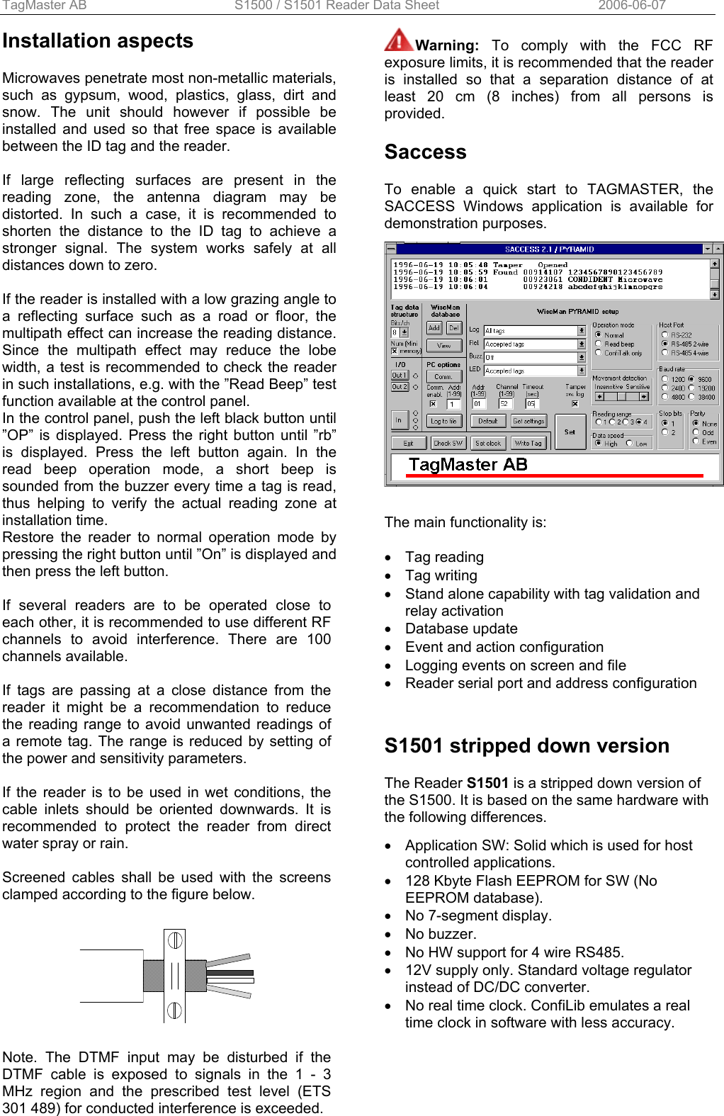
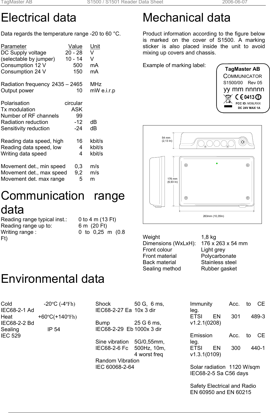
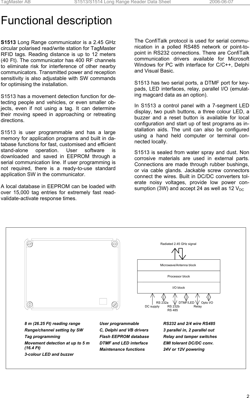
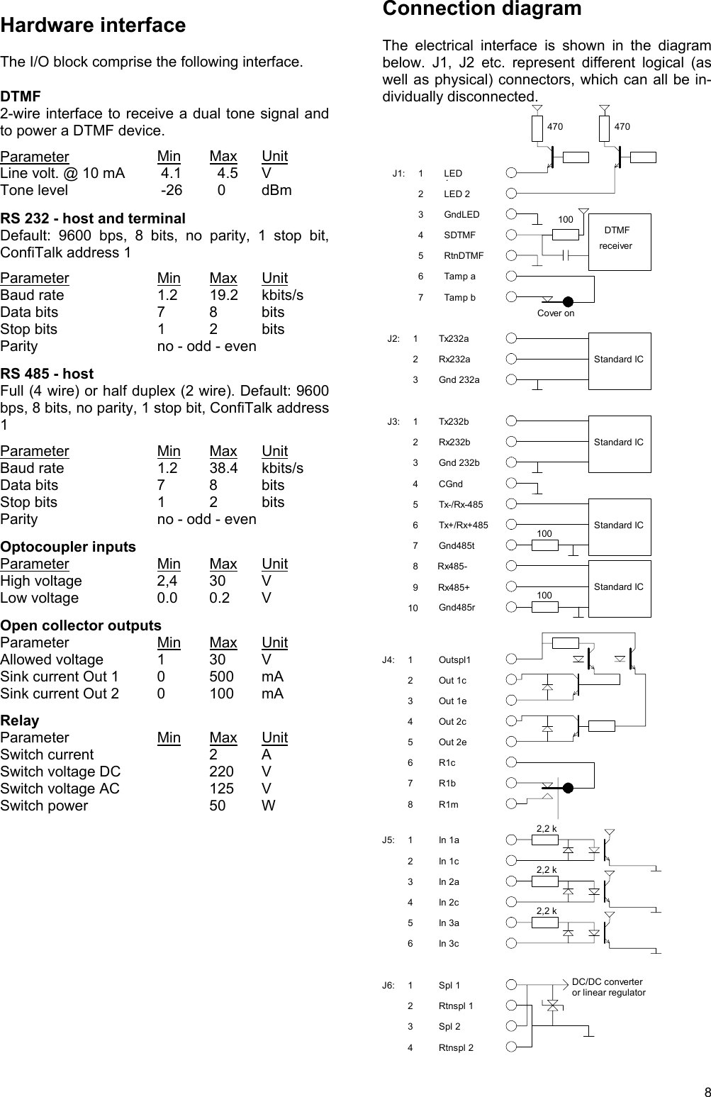
![TagMaster AB S1500 / S1501 Reader Data Sheet Issue 01 Copyright The copyright/ownership of this document is and will remain ours. The document must not be used without our authorization or brought to the knowledge of a third party. TagMaster AB. Disclaimer The information in this document is subject to change without notice. While the information contained herein is assumed to be accurate, TagMaster AB assumes no responsibility for any errors or omissions. Reading/writing range The maximum reading or writing range is defined as the maximum distance along the radiation axis where the tag can be communicated when the tag and reader face each other and when there is free space in between. The free space reading range for S1500 is up to more than 6 m (20 Ft). In a typical installation the reading range is up to 4m (13 Ft) Writing range is up to 0.25 m (0.8 Ft) The reading range depends on the tag reflectivity, the data speed (high/low), power output and sensitivity settings. If using low power and/or low sensitivity the reading range is reduced according to the following table. Range Sensitivity Power Range factor 4 HIGH HIGH 100% 3 HIGH LOW 50% 2 LOW HIGH 25% 1 LOW LOW 12% Writing must be done at high power. The writing range is normally not affected by speed and sensitivity settings. Lobe width The lobe diagram shows, in a proportional scale, the approximate lobe shapes of the S1500 and S1501 readers. Curves 4, 3, 2 and 1 show areas for safe reading for the four different combinations of power and sensitivity. Example: Your reading range has been calculated to 4.0 meters, meaning each square in the diagram is 4.0/10=0.4 meters. The lobe width at 70% range is then 5.5 squares * 0.4 = 2.2 meters. The diagram concerns a free space installation, and does not take into account possible influences from signal reflections or attenuating structures. For reliability reasons, it is recommended that tags are passing at 70 % or less of specified reading and writing range. Reading/writing time The time for reading and writing tags are specified in the tag data sheets. Please refer to the data sheet of the specific tag concerned. Passage speed The table shows the maximum allowed passage speed in km/h for combinations of tag reading time and lobe widths. Lobe width [m] Reading time [ms] 1 1.5 2.0 2.5 3.0 20 180 270 360 450 540 50 72 108 144 180 216 70 51 77 103 129 154 100 36 54 72 90 108 130 28 42 56 69 83 150 24 36 48 60 72 200 18 27 36 45 54 Tag orientation Thanks to the circular polarisation, the reading and writing ranges are independent from the rotational orientation around the radiation axis. The reading time for the tag, can be found in the tag datasheets. If the ID tag is tilted in relation to the reader, a range reduction may occur. Since this effect depends mainly on the specific installation, it is recommended that a test is made. S1500 can be set to a "read beep" mode to conveniently check out the reading range. Movement detection S1500 detects a moving person or car at up to 5 meters (16Ft) distance, even when moving slowly. The reader senses if the object is approaching or moving away from the reader, and at what radial](https://usermanual.wiki/Tagmaster/LRXX.Data-sheets/User-Guide-687361-Page-4.png)
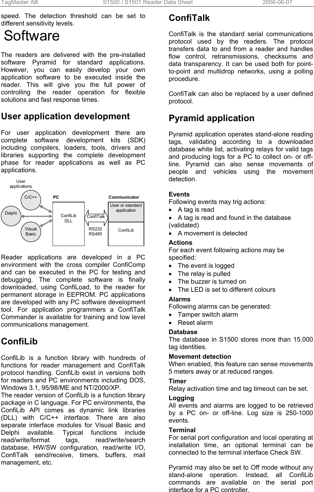
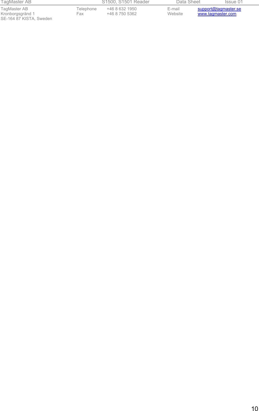
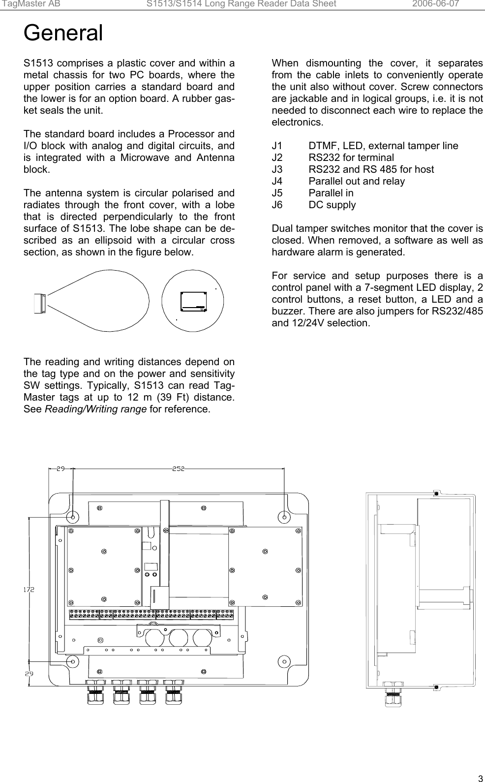
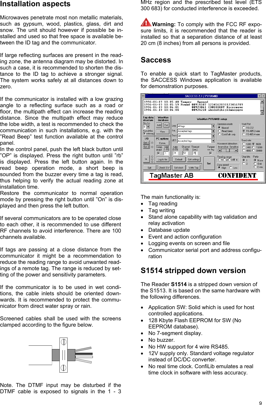
![TagMaster AB S1500 / S1501 Reader Data Sheet Issue 01 Copyright The copyright/ownership of this document is and will remain ours. The document must not be used without our authorization or brought to the knowledge of a third party. TagMaster AB. Disclaimer The information in this document is subject to change without notice. While the information contained herein is assumed to be accurate, TagMaster AB assumes no responsibility for any errors or omissions. Reading/writing range The maximum reading or writing range is defined as the maximum distance along the radiation axis where the tag can be communicated when the tag and communicator face each other and when there is free space in between. The free space reading range for S1513 is up to more than 12 m (39 Ft). In a typical installation the reading range is up to 8 m (26 Ft) Writing range is up to 1.2 m (4 Ft) The reading range depends on the tag reflectivity, the data speed (high/low), power output and sen-sitivity settings. If using low power and/or low sensitivity the read-ing range is reduced according to the following table. Range Sensitivity Power Range factor 4 HIGH HIGH 100% 3 HIGH LOW 50% 2 LOW HIGH 25% 1 LOW LOW 12% Writing must be done at high power. The writing range is normally not affected by speed and sen-sitivity settings. Lobe width The lobe diagram shows, in a proportional scale, the approximate lobe shapes of the S1513 and S1514 readers. Curves 4, 3, 2 and 1 show areas for safe reading for the four different combinations of power and sensitivity. Example: Your reading range has been calculated to 8.0 meters, meaning each square in the dia-gram is 8.0/10=0.8 meters. The lobe width at 70% range is then 5.5 squares * 0.8 = 4.4 meters. The diagram concerns a free space installation, and does not take into account possible influ-ences from signal reflections or attenuating struc-tures. For reliability reasons, it is recommended that tags are passing at 70 % or less of maximum reading and writing range. Reading/writing time The time for reading and writing tags are specified in the tag data sheets. Please refer to the data sheet of the specific tag concerned. Passage speed The table shows the maximum allowed passage speed in km/h for combinations of tag reading time and lobe widths. Lobe width [m] Reading time [ms] 1 1.5 2.0 2.5 3.0 20 180 270 360 450 540 50 72 108 144 180 216 70 51 77 103 129 154 100 36 54 72 90 108 130 28 42 56 69 83 150 24 36 48 60 72 200 18 27 36 45 54 Tag orientation Thanks to the circular polarisation, the reading and writing ranges are independent from the rota-tional orientation around the radiation axis. How-ever, if the ID tag is very tilted in relation to the communicator, a range reduction may occur. Since this effect depends mainly on the specific installation, it is recommended that a test is made. S1513 can be set to a "read beep" mode to con-veniently check out the reading range. Movement detection S1513 detects a moving person or car at up to 10 m (33 Ft) distance, even when moving slowly. The communicator senses if the object is approaching or moving away from the communicator, and at](https://usermanual.wiki/Tagmaster/LRXX.Data-sheets/User-Guide-687361-Page-14.png)

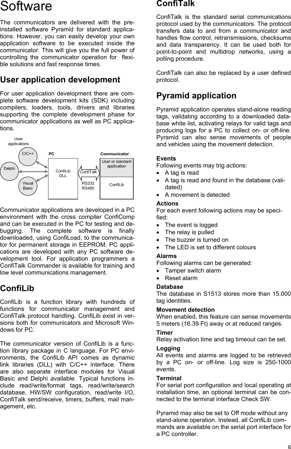
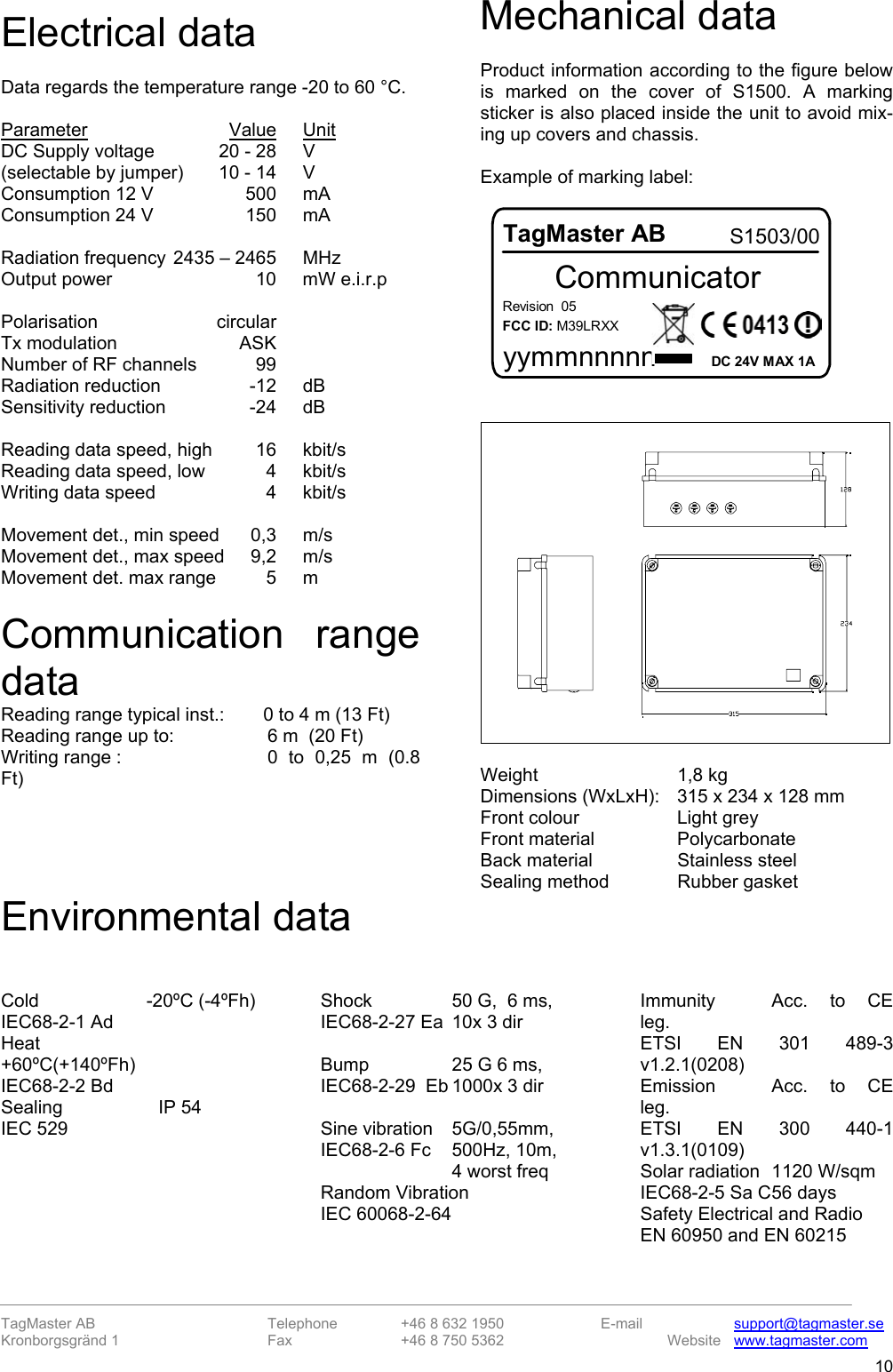

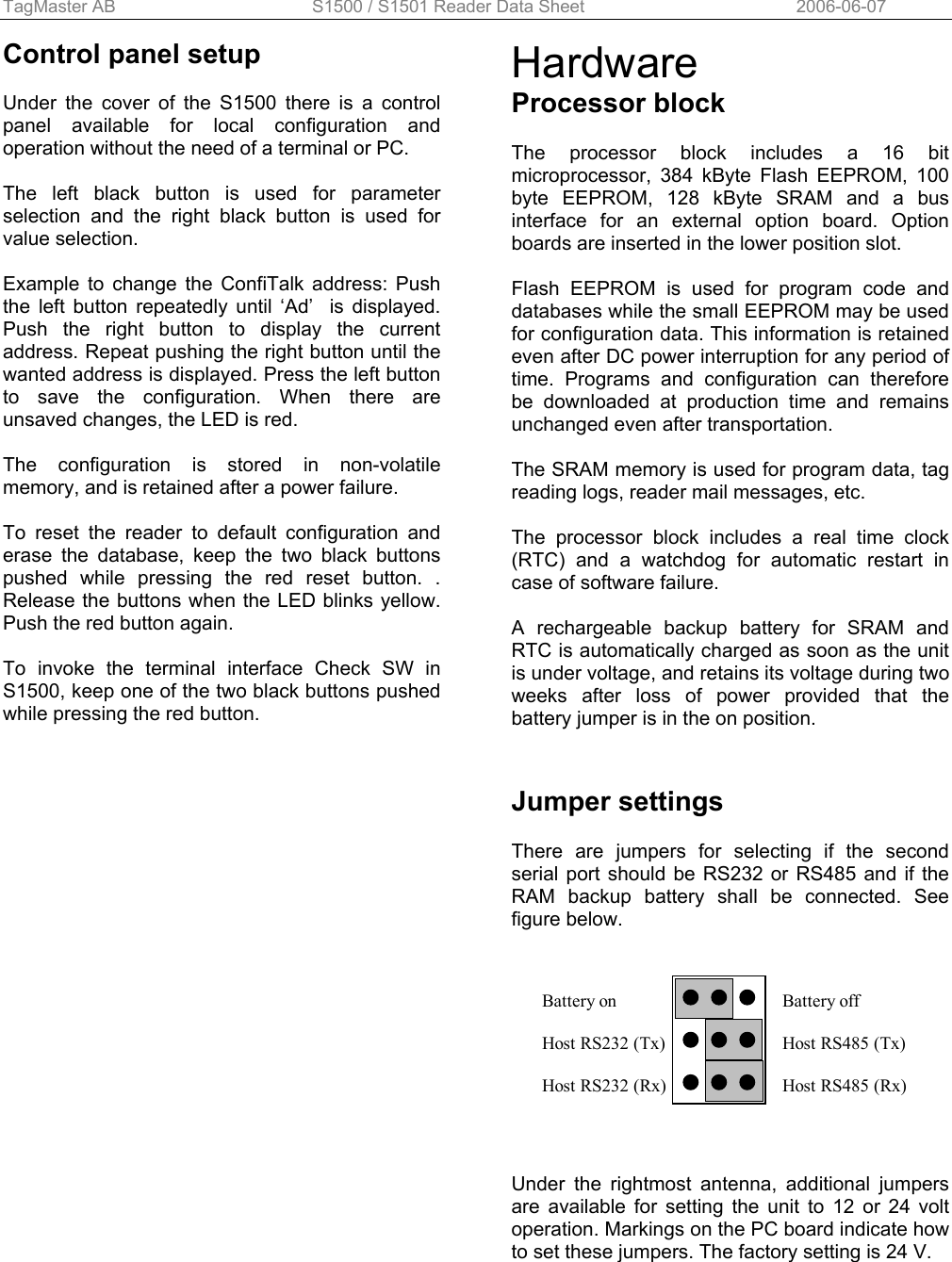
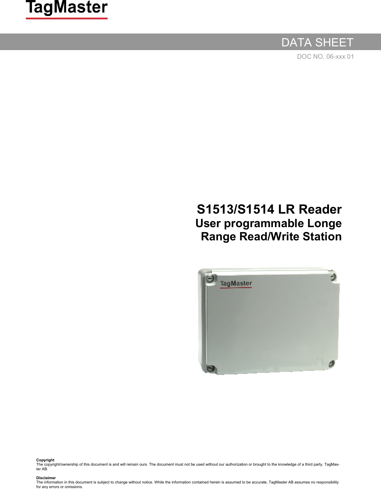
![TagMaster AB S1566 HD Reader Data Sheet 2006-06-07 3Reading/writing range The maximum reading or writing range is defined as the maximum distance along the radiation axis where the tag can be communicated when the tag and reader face each other and when there is free space in between. The free space reading range for S1566 is up to more than 6 m (20 Ft). In a typical installation the reading range is up to 4m (13 Ft) Writing range is up to 0.25 m (0.8 Ft) The reading range depends on the tag reflectivity, the data speed (high/low), power output and sensitivity settings. If using low power and/or low sensitivity the reading range is reduced according to the following table. Range Sensitivity Power Range factor 4 HIGH HIGH 100% 3 HIGH LOW 50% 2 LOW HIGH 25% 1 LOW LOW 12% Writing must be done at high power. The writing range is normally not affected by speed and sensitivity settings. Lobe width The lobe diagram shows, in a proportional scale, the approximate lobe shapes of the S1566 readers. Curves 4, 3, 2 and 1 show areas for safe reading for the four different combinations of power and sensitivity. Example: Your reading range has been calculated to 4.0 meters, meaning each square in the diagram is 4.0/10=0.4 meters. The lobe width at 70% range is then 5.5 squares * 0.4 = 2.2 meters. The diagram concerns a free space installation, and does not take into account possible influences from signal reflections or attenuating structures. For reliability reasons, it is recommended that tags are passing at 70 % or less of specified reading and writing range. Reading/writing time The time for reading and writing tags are specified in the tag data sheets. Please refer to the data sheet of the specific tag concerned. Passage speed The table shows the maximum allowed passage speed in km/h for combinations of tag reading time and lobe widths. Lobe width [m] Reading time [ms] 1 1.5 2.0 2.5 3.0 20 180 270 360 450 540 50 72 108 144 180 216 70 51 77 103 129 154 100 36 54 72 90 108 130 28 42 56 69 83 150 24 36 48 60 72 200 18 27 36 45 54 Tag orientation Thanks to the circular polarisation, the reading and writing ranges are independent from the rotational orientation around the radiation axis. The reading time for the tag, can be found in the tag datasheets. If the ID tag is very tilted in relation to the reader, a range reduction may occur. Since this effect depends mainly on the specific installation, it is recommended that a test is made.](https://usermanual.wiki/Tagmaster/LRXX.Data-sheets/User-Guide-687361-Page-24.png)