Tagmaster LRXX RFID Reader User Manual Installation manual
Tagmaster AB RFID Reader Installation manual
UserManual.wiki
>
Tagmaster
>
LRXX User Manual
>
Installation manual
Contents
1.
Installation guide
2.
Data sheets
3.
Installation manual
4.
User manual
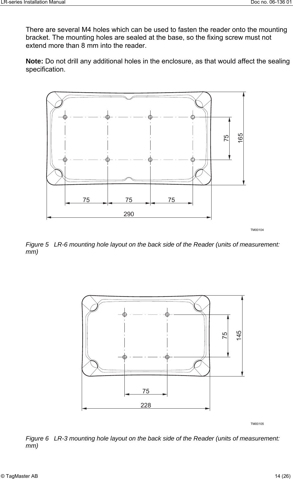
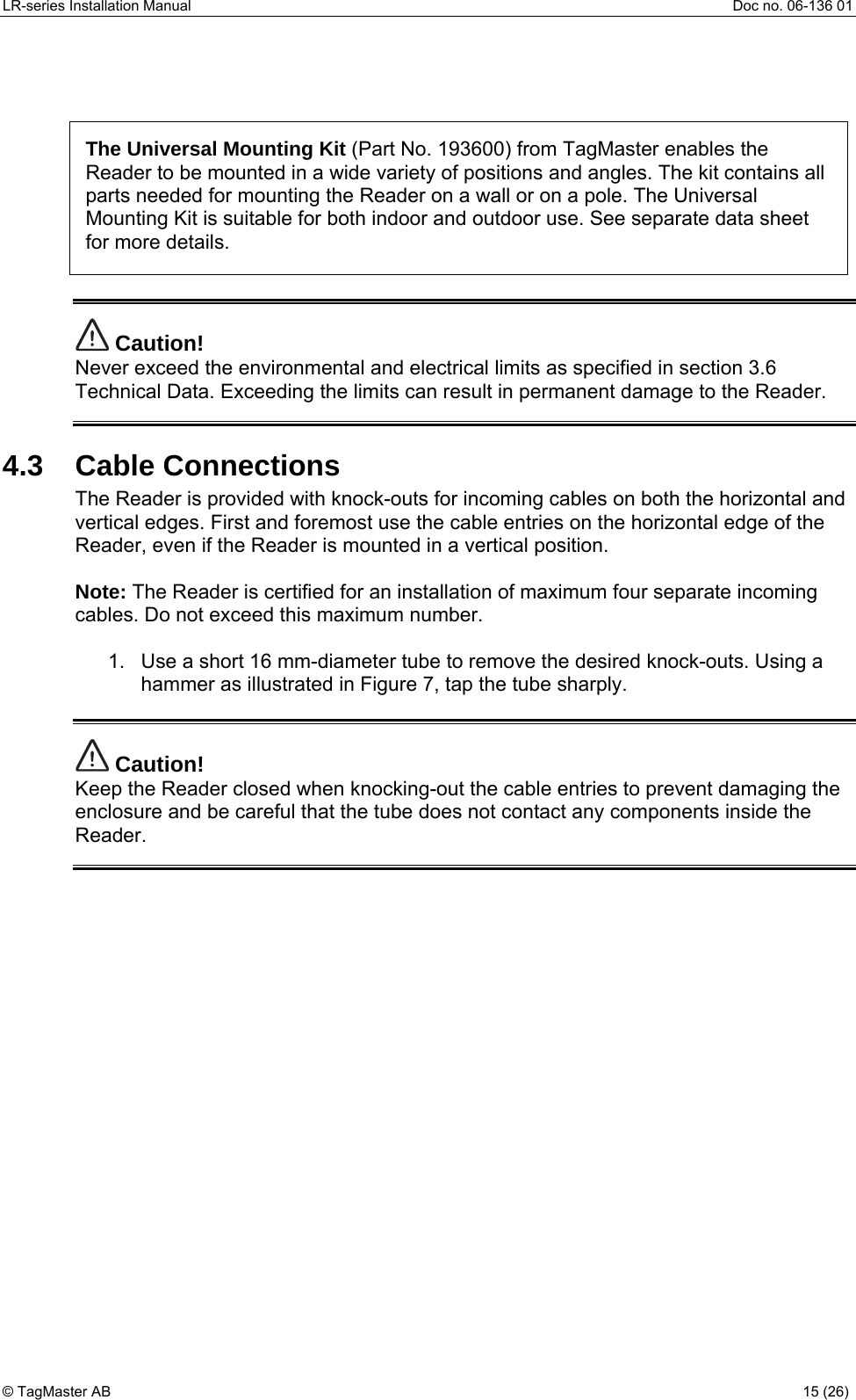
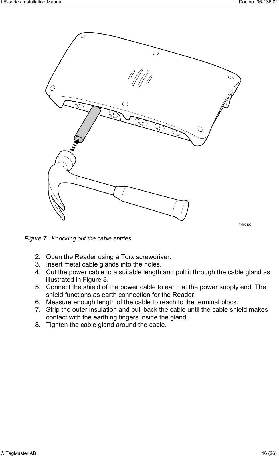
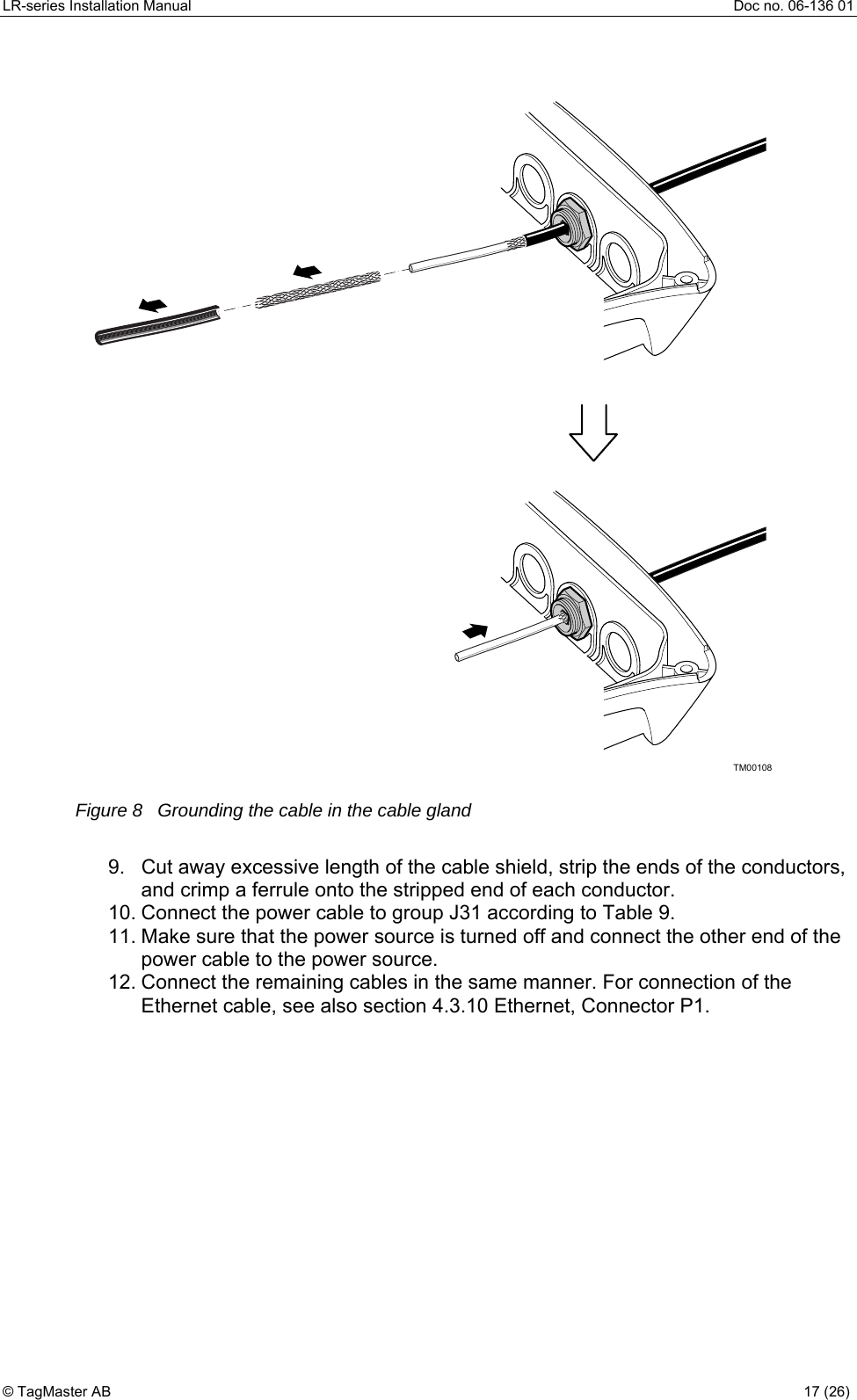
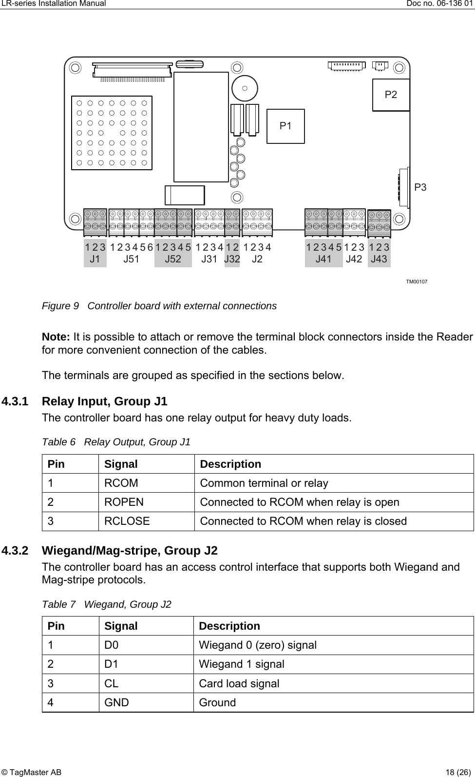
Installation manual
Navigation menu
Upload a User Manual
Namespaces
Wiki Guide
HTML
PDF
Info
Views
User Manual
Discussion / Help
Navigation