Tagsys CONVYRANT Conveyor Antenna User Manual ConveyAntInstall270
Tagsys S.A. Conveyor Antenna ConveyAntInstall270
UserManual.wiki
>
Tagsys
>
CONVYRANT User Manual
>
Installation Guide
Contents
1.
Installation
2.
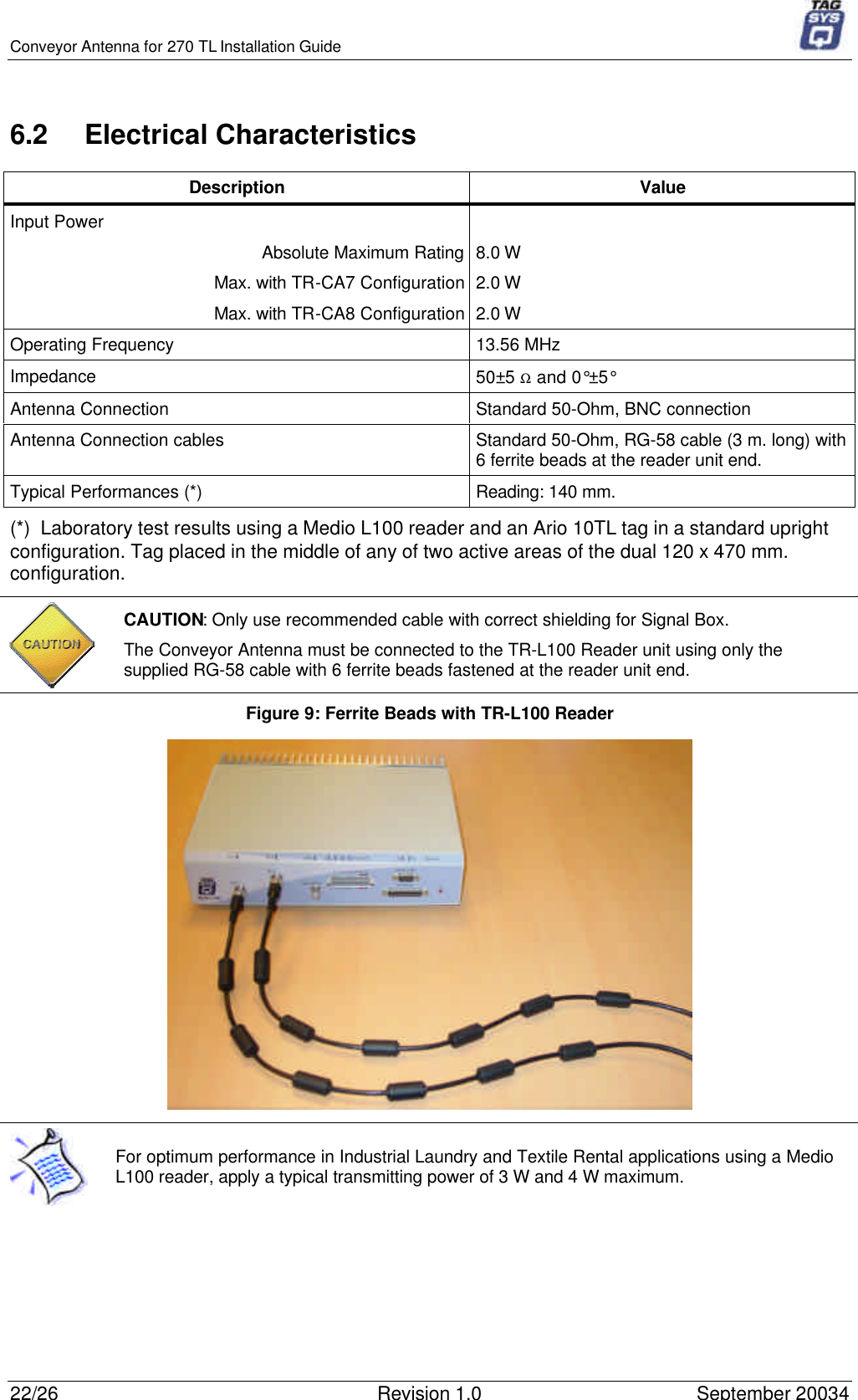
Installation Guide
Installation Guide
Navigation menu
Upload a User Manual
Namespaces
Wiki Guide
HTML
PDF
Info
Views
User Manual
Discussion / Help
Navigation