Tagsys MEDIOP101WIFI RFID Tag Reader User Manual Manual
Tagsys S.A. RFID Tag Reader Manual
UserManual.wiki
>
Tagsys
>
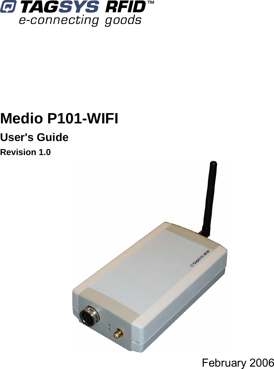
MEDIOP101WIFI User Manual
>
Manual
Contents
1.
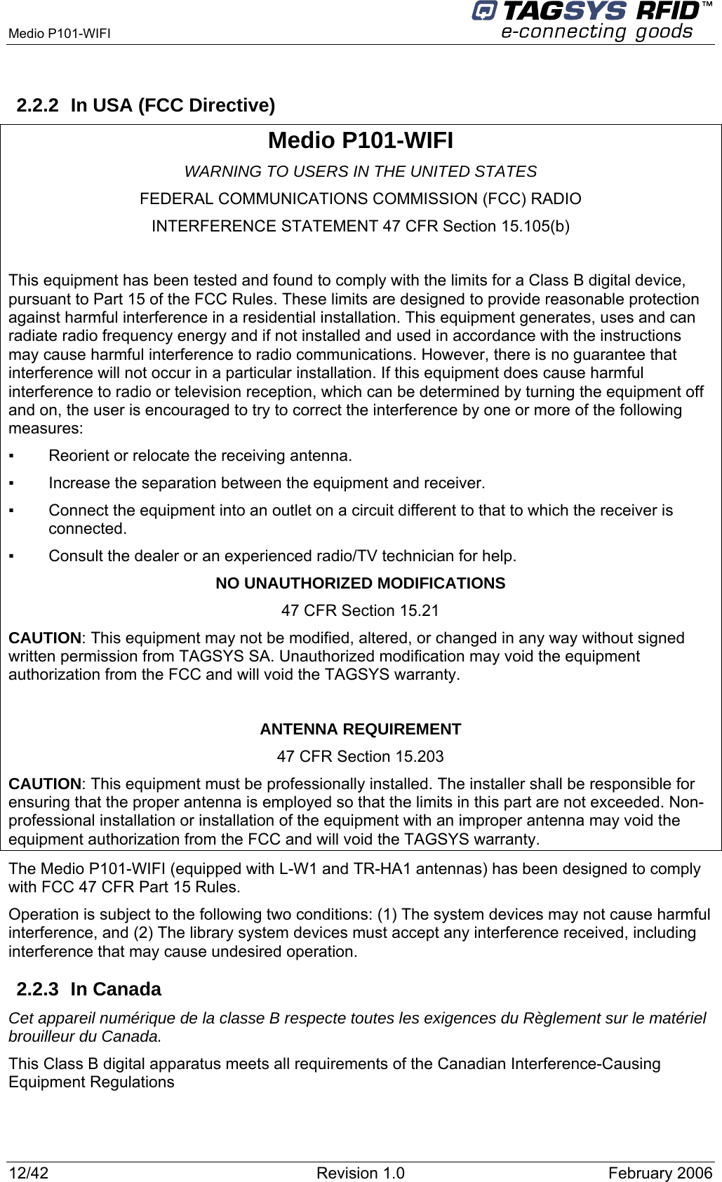
FCC Statement
2.
Manual
Manual
Navigation menu
Upload a User Manual
Namespaces
Wiki Guide
HTML
PDF
Info
Views
User Manual
Discussion / Help
Navigation