Tait TBBH5A Base Station Transceiver User Manual TB7100 Installation and Operation Manual
Tait Limited Base Station Transceiver TB7100 Installation and Operation Manual
Tait >
Exhibit D Users Manual per 2 1033 c3

TB7100 base station
Installation and
Operation Manual
MBB-00001-02
Issue 2
December 2005

2TB7100 Installation and Operation Manual
© Tait Electronics Limited December 2005
Tait Contact Information
Tait Radio Communications
Corporate Head Office
Tait Electronics Ltd
P.O. Box 1645
Christchurch
New Zealand
For the address and telephone number of
regional offices, refer to the TaitWorld
website:
Website: http://www.taitworld.com
Technical Support
For assistance with specific technical issues,
contact Technical Support:
E-mail: support@taitworld.com
Website: http://support.taitworld.com
To our European customers:
Tait Electronics Limited is an environmentally responsible company which
supports waste minimization and material recovery. The European Union’s
Waste Electrical and Electronic Equipment Directive requires that this
product be disposed of separately from the general waste stream when its
service life is over. Please be environmentally responsible and dispose
through the original supplier, your local municipal waste “separate
collection” service, or contact Tait Electronics Limited.

TB7100 Installation and Operation Manual 3
© Tait Electronics Limited May 2005
Contents
Preface . . . . . . . . . . . . . . . . . . . . . . . . . . . . . . . . . . . . . . . . . . . . . . . . . . . . . 7
Scope of Manual . . . . . . . . . . . . . . . . . . . . . . . . . . . . . . . . . . . . . . . . . . . . . . . . . . . .7
Enquiries and Comments . . . . . . . . . . . . . . . . . . . . . . . . . . . . . . . . . . . . . . . . . . . . . .7
Updates of Manual and Equipment . . . . . . . . . . . . . . . . . . . . . . . . . . . . . . . . . . . . . . .7
Copyright . . . . . . . . . . . . . . . . . . . . . . . . . . . . . . . . . . . . . . . . . . . . . . . . . . . . . . . . .7
Disclaimer . . . . . . . . . . . . . . . . . . . . . . . . . . . . . . . . . . . . . . . . . . . . . . . . . . . . . . . . .7
Document Conventions . . . . . . . . . . . . . . . . . . . . . . . . . . . . . . . . . . . . . . . . . . . . . . .8
Associated Documentation . . . . . . . . . . . . . . . . . . . . . . . . . . . . . . . . . . . . . . . . . . . . .8
Publication Record . . . . . . . . . . . . . . . . . . . . . . . . . . . . . . . . . . . . . . . . . . . . . . . . . .9
1 Introduction . . . . . . . . . . . . . . . . . . . . . . . . . . . . . . . . . . . . . . . . . . . . . . 11
1.1 Frequency Bands . . . . . . . . . . . . . . . . . . . . . . . . . . . . . . . . . . . . . . . . . . . . . . . 12
1.2 RF Output Power . . . . . . . . . . . . . . . . . . . . . . . . . . . . . . . . . . . . . . . . . . . . . . 12
1.3 Power Supply Options . . . . . . . . . . . . . . . . . . . . . . . . . . . . . . . . . . . . . . . . . . . 13
1.4 Mechanical Configurations . . . . . . . . . . . . . . . . . . . . . . . . . . . . . . . . . . . . . . . . 13
1.5 Product Codes . . . . . . . . . . . . . . . . . . . . . . . . . . . . . . . . . . . . . . . . . . . . . . . . . 14
2 Mechanical Description . . . . . . . . . . . . . . . . . . . . . . . . . . . . . . . . . . . . . . 15
2.1 Tray. . . . . . . . . . . . . . . . . . . . . . . . . . . . . . . . . . . . . . . . . . . . . . . . . . . . . . . . . 16
2.2 UI Board . . . . . . . . . . . . . . . . . . . . . . . . . . . . . . . . . . . . . . . . . . . . . . . . . . . . . 16
2.3 Receiver Module . . . . . . . . . . . . . . . . . . . . . . . . . . . . . . . . . . . . . . . . . . . . . . . 17
2.4 Transmitter Module . . . . . . . . . . . . . . . . . . . . . . . . . . . . . . . . . . . . . . . . . . . . . 18
2.5 SI Board. . . . . . . . . . . . . . . . . . . . . . . . . . . . . . . . . . . . . . . . . . . . . . . . . . . . . . 19
2.6 AC Power Supply Unit. . . . . . . . . . . . . . . . . . . . . . . . . . . . . . . . . . . . . . . . . . . 20
3 Functional Description. . . . . . . . . . . . . . . . . . . . . . . . . . . . . . . . . . . . . . . 21
3.1 Receiver Operation . . . . . . . . . . . . . . . . . . . . . . . . . . . . . . . . . . . . . . . . . . . . . 23
3.1.1 RF Hardware . . . . . . . . . . . . . . . . . . . . . . . . . . . . . . . . . . . . . . . . . . 23
3.1.2 Digital Baseband Processing. . . . . . . . . . . . . . . . . . . . . . . . . . . . . . . . 24
3.1.3 Audio Processing and Signalling. . . . . . . . . . . . . . . . . . . . . . . . . . . . . 25
3.2 Transmitter Operation . . . . . . . . . . . . . . . . . . . . . . . . . . . . . . . . . . . . . . . . . . . 26
3.2.1 Audio Processing and Signalling. . . . . . . . . . . . . . . . . . . . . . . . . . . . . 26
3.2.2 Frequency Synthesizer. . . . . . . . . . . . . . . . . . . . . . . . . . . . . . . . . . . . 27
3.2.3 RF Power Amplifier . . . . . . . . . . . . . . . . . . . . . . . . . . . . . . . . . . . . . 30
3.3 User Interface Operation. . . . . . . . . . . . . . . . . . . . . . . . . . . . . . . . . . . . . . . . . . 32
3.4 System Interface Operation . . . . . . . . . . . . . . . . . . . . . . . . . . . . . . . . . . . . . . . . 35
3.4.1 Internal Power Distribution . . . . . . . . . . . . . . . . . . . . . . . . . . . . . . . . 37
3.4.2 Serial Data . . . . . . . . . . . . . . . . . . . . . . . . . . . . . . . . . . . . . . . . . . . . 38
3.4.3 General Purpose IO. . . . . . . . . . . . . . . . . . . . . . . . . . . . . . . . . . . . . . 38
3.4.4 Receiver Audio Processing . . . . . . . . . . . . . . . . . . . . . . . . . . . . . . . . 38
3.4.5 Tone On Idle . . . . . . . . . . . . . . . . . . . . . . . . . . . . . . . . . . . . . . . . . . 38
3.4.6 Transmitter Audio Processing. . . . . . . . . . . . . . . . . . . . . . . . . . . . . . . 38
4TB7100 Installation and Operation Manual
© Tait Electronics Limited May 2005
3.4.7 Opto Isolated Keying . . . . . . . . . . . . . . . . . . . . . . . . . . . . . . . . . . . . 39
3.4.8 Relay Output. . . . . . . . . . . . . . . . . . . . . . . . . . . . . . . . . . . . . . . . . . 39
3.4.9 Fan Control . . . . . . . . . . . . . . . . . . . . . . . . . . . . . . . . . . . . . . . . . . . 39
3.4.10 RSSI . . . . . . . . . . . . . . . . . . . . . . . . . . . . . . . . . . . . . . . . . . . . . . . . 39
3.4.11 Receiver Gate. . . . . . . . . . . . . . . . . . . . . . . . . . . . . . . . . . . . . . . . . . 39
3.4.12 Receiver Inhibit . . . . . . . . . . . . . . . . . . . . . . . . . . . . . . . . . . . . . . . . 39
3.5 Fan Operation . . . . . . . . . . . . . . . . . . . . . . . . . . . . . . . . . . . . . . . . . . . . . . . . . 40
4 Installation . . . . . . . . . . . . . . . . . . . . . . . . . . . . . . . . . . . . . . . . . . . . . . . 41
4.1 Personal Safety. . . . . . . . . . . . . . . . . . . . . . . . . . . . . . . . . . . . . . . . . . . . . . . . . 41
4.1.1 Lethal Voltages . . . . . . . . . . . . . . . . . . . . . . . . . . . . . . . . . . . . . . . . . 41
4.1.2 Explosive Environments . . . . . . . . . . . . . . . . . . . . . . . . . . . . . . . . . . 42
4.1.3 Proximity to RF Transmissions . . . . . . . . . . . . . . . . . . . . . . . . . . . . . 42
4.1.4 High Temperatures. . . . . . . . . . . . . . . . . . . . . . . . . . . . . . . . . . . . . . 42
4.2 Equipment Safety. . . . . . . . . . . . . . . . . . . . . . . . . . . . . . . . . . . . . . . . . . . . . . . 42
4.2.1 ESD Precautions. . . . . . . . . . . . . . . . . . . . . . . . . . . . . . . . . . . . . . . . 42
4.2.2 Antenna Load. . . . . . . . . . . . . . . . . . . . . . . . . . . . . . . . . . . . . . . . . . 43
4.2.3 Equipment Grounding . . . . . . . . . . . . . . . . . . . . . . . . . . . . . . . . . . . 43
4.2.4 Installation and Servicing Personnel . . . . . . . . . . . . . . . . . . . . . . . . . . 43
4.3 Regulatory Information . . . . . . . . . . . . . . . . . . . . . . . . . . . . . . . . . . . . . . . . . . 43
4.3.1 Distress Frequencies . . . . . . . . . . . . . . . . . . . . . . . . . . . . . . . . . . . . . 43
4.3.2 FCC Compliance . . . . . . . . . . . . . . . . . . . . . . . . . . . . . . . . . . . . . . . 44
4.3.3 Unauthorised Modifications. . . . . . . . . . . . . . . . . . . . . . . . . . . . . . . . 44
4.3.4 Health, Safety and Electromagnetic Compatibility in Europe. . . . . . . . 44
4.4 Environmental Conditions . . . . . . . . . . . . . . . . . . . . . . . . . . . . . . . . . . . . . . . . 45
4.4.1 Operating Temperature Range . . . . . . . . . . . . . . . . . . . . . . . . . . . . . 45
4.4.2 Humidity . . . . . . . . . . . . . . . . . . . . . . . . . . . . . . . . . . . . . . . . . . . . . 45
4.4.3 Dust and Dirt . . . . . . . . . . . . . . . . . . . . . . . . . . . . . . . . . . . . . . . . . . 45
4.5 Grounding and Lightning Protection. . . . . . . . . . . . . . . . . . . . . . . . . . . . . . . . . 45
4.5.1 Electrical Ground . . . . . . . . . . . . . . . . . . . . . . . . . . . . . . . . . . . . . . . 45
4.5.2 Lightning Ground. . . . . . . . . . . . . . . . . . . . . . . . . . . . . . . . . . . . . . . 45
4.6 Recommended Tools. . . . . . . . . . . . . . . . . . . . . . . . . . . . . . . . . . . . . . . . . . . . 46
4.7 Ventilation. . . . . . . . . . . . . . . . . . . . . . . . . . . . . . . . . . . . . . . . . . . . . . . . . . . . 46
4.7.1 Cabinet and Rack Ventilation . . . . . . . . . . . . . . . . . . . . . . . . . . . . . . 46
4.8 Installing the Base Station . . . . . . . . . . . . . . . . . . . . . . . . . . . . . . . . . . . . . . . . . 49
4.8.1 Unpacking the Equipment. . . . . . . . . . . . . . . . . . . . . . . . . . . . . . . . . 49
4.8.2 Identifying the Mechanical Configuration . . . . . . . . . . . . . . . . . . . . . 49
4.8.3 Power Supply Options . . . . . . . . . . . . . . . . . . . . . . . . . . . . . . . . . . . 50
4.8.4 Setting the AC Mains Input Voltage . . . . . . . . . . . . . . . . . . . . . . . . . 50
4.8.5 Mounting the Base Station . . . . . . . . . . . . . . . . . . . . . . . . . . . . . . . . 51
4.8.6 Cabling . . . . . . . . . . . . . . . . . . . . . . . . . . . . . . . . . . . . . . . . . . . . . . 52
4.8.7 Accessories . . . . . . . . . . . . . . . . . . . . . . . . . . . . . . . . . . . . . . . . . . . . 52
5 Replacing Modules . . . . . . . . . . . . . . . . . . . . . . . . . . . . . . . . . . . . . . . . . 53
5.1 Removing the Base Station and Opening the Tray. . . . . . . . . . . . . . . . . . . . . . . 54
5.2 Replacing the UI Board . . . . . . . . . . . . . . . . . . . . . . . . . . . . . . . . . . . . . . . . . . 55
5.3 Replacing the Receiver Module . . . . . . . . . . . . . . . . . . . . . . . . . . . . . . . . . . . . 56
5.4 Replacing the Transmitter Module . . . . . . . . . . . . . . . . . . . . . . . . . . . . . . . . . . 57
TB7100 Installation and Operation Manual 5
© Tait Electronics Limited May 2005
5.5 Replacing the SI Board. . . . . . . . . . . . . . . . . . . . . . . . . . . . . . . . . . . . . . . . . . . 58
5.6 Replacing the Transmitter and Receiver Fans . . . . . . . . . . . . . . . . . . . . . . . . . . 59
5.7 Replacing the Fan Power Board . . . . . . . . . . . . . . . . . . . . . . . . . . . . . . . . . . . . 60
5.8 Replacing the Temperature Sensor Board . . . . . . . . . . . . . . . . . . . . . . . . . . . . . 60
5.9 Replacing the AC Power Supply Unit, Fan and Filter Module . . . . . . . . . . . . . .61
5.10 Replacing the Speaker . . . . . . . . . . . . . . . . . . . . . . . . . . . . . . . . . . . . . . . . . . . 62
5.11 Final Reassembly . . . . . . . . . . . . . . . . . . . . . . . . . . . . . . . . . . . . . . . . . . . . . . . 63
6 Connections . . . . . . . . . . . . . . . . . . . . . . . . . . . . . . . . . . . . . . . . . . . . . . 65
6.1 External Connectors . . . . . . . . . . . . . . . . . . . . . . . . . . . . . . . . . . . . . . . . . . . . . 66
6.2 Internal Connectors . . . . . . . . . . . . . . . . . . . . . . . . . . . . . . . . . . . . . . . . . . . . . 71
6.2.1 Transmitter and Receiver Connectors . . . . . . . . . . . . . . . . . . . . . . . . 71
6.2.2 SI Board Connectors. . . . . . . . . . . . . . . . . . . . . . . . . . . . . . . . . . . . . 73
6.2.3 UI Board Connectors . . . . . . . . . . . . . . . . . . . . . . . . . . . . . . . . . . . . 75
7 Preparation for Operation. . . . . . . . . . . . . . . . . . . . . . . . . . . . . . . . . . . . . 77
7.1 Introduction. . . . . . . . . . . . . . . . . . . . . . . . . . . . . . . . . . . . . . . . . . . . . . . . . . . 77
7.2 Mode of Operation. . . . . . . . . . . . . . . . . . . . . . . . . . . . . . . . . . . . . . . . . . . . . . 77
7.3 Line-controlled Base. . . . . . . . . . . . . . . . . . . . . . . . . . . . . . . . . . . . . . . . . . . . . 78
7.3.1 Test Equipment Required . . . . . . . . . . . . . . . . . . . . . . . . . . . . . . . . . 78
7.3.2 Test Equipment Setup. . . . . . . . . . . . . . . . . . . . . . . . . . . . . . . . . . . . 79
7.3.3 Link Settings. . . . . . . . . . . . . . . . . . . . . . . . . . . . . . . . . . . . . . . . . . . 80
7.3.4 Applying Power . . . . . . . . . . . . . . . . . . . . . . . . . . . . . . . . . . . . . . . . 81
7.3.5 Programming . . . . . . . . . . . . . . . . . . . . . . . . . . . . . . . . . . . . . . . . . . 82
7.3.6 Receiver Audio Level Adjustment . . . . . . . . . . . . . . . . . . . . . . . . . . . 83
7.3.7 Receiver Functional Testing . . . . . . . . . . . . . . . . . . . . . . . . . . . . . . . 84
7.3.8 Transmitter Audio Level Adjustment . . . . . . . . . . . . . . . . . . . . . . . . . 85
7.3.9 Transmitter Functional Testing . . . . . . . . . . . . . . . . . . . . . . . . . . . . .86
7.4 Talk Through Repeater . . . . . . . . . . . . . . . . . . . . . . . . . . . . . . . . . . . . . . . . . . 88
7.4.1 Test Equipment Required . . . . . . . . . . . . . . . . . . . . . . . . . . . . . . . . . 88
7.4.2 Test Equipment Setup. . . . . . . . . . . . . . . . . . . . . . . . . . . . . . . . . . . . 89
7.4.3 Link Settings. . . . . . . . . . . . . . . . . . . . . . . . . . . . . . . . . . . . . . . . . . . 89
7.4.4 Applying Power . . . . . . . . . . . . . . . . . . . . . . . . . . . . . . . . . . . . . . . . 90
7.4.5 Programming . . . . . . . . . . . . . . . . . . . . . . . . . . . . . . . . . . . . . . . . . . 90
7.4.6 Audio Level Adjustment . . . . . . . . . . . . . . . . . . . . . . . . . . . . . . . . . . 91
7.4.7 Talk Through Repeater Functional Testing . . . . . . . . . . . . . . . . . . . . 91
7.4.8 Alternate Talk Through Repeater Configuration . . . . . . . . . . . . . . . . 92
7.5 RF Modem . . . . . . . . . . . . . . . . . . . . . . . . . . . . . . . . . . . . . . . . . . . . . . . . . . . 93
7.5.1 Test Equipment Required . . . . . . . . . . . . . . . . . . . . . . . . . . . . . . . . . 93
7.5.2 Test Equipment Setup. . . . . . . . . . . . . . . . . . . . . . . . . . . . . . . . . . . . 94
7.5.3 Link Settings. . . . . . . . . . . . . . . . . . . . . . . . . . . . . . . . . . . . . . . . . . . 94
7.5.4 Applying Power . . . . . . . . . . . . . . . . . . . . . . . . . . . . . . . . . . . . . . . . 95
7.5.5 Programming . . . . . . . . . . . . . . . . . . . . . . . . . . . . . . . . . . . . . . . . . . 96
7.5.6 Audio Level Adjustment . . . . . . . . . . . . . . . . . . . . . . . . . . . . . . . . . . 96
7.5.7 Programming for FFSK Operation. . . . . . . . . . . . . . . . . . . . . . . . . . . 96
7.5.8 Programming for THSD Operation . . . . . . . . . . . . . . . . . . . . . . . . . . 98
7.5.9 Verification. . . . . . . . . . . . . . . . . . . . . . . . . . . . . . . . . . . . . . . . . . . 100
6TB7100 Installation and Operation Manual
© Tait Electronics Limited May 2005
7.6 Data Repeater . . . . . . . . . . . . . . . . . . . . . . . . . . . . . . . . . . . . . . . . . . . . . . . . 101
7.6.1 Link Settings. . . . . . . . . . . . . . . . . . . . . . . . . . . . . . . . . . . . . . . . . . 102
7.6.2 Applying Power . . . . . . . . . . . . . . . . . . . . . . . . . . . . . . . . . . . . . . . 103
7.6.3 Programming . . . . . . . . . . . . . . . . . . . . . . . . . . . . . . . . . . . . . . . . . 103
7.6.4 Audio Level Adjustment . . . . . . . . . . . . . . . . . . . . . . . . . . . . . . . . . 103
7.6.5 Data Repeater Functional Testing . . . . . . . . . . . . . . . . . . . . . . . . . . 104
7.7 TaitNet Trunking . . . . . . . . . . . . . . . . . . . . . . . . . . . . . . . . . . . . . . . . . . . . . 104
7.8 Programmable Features. . . . . . . . . . . . . . . . . . . . . . . . . . . . . . . . . . . . . . . . . . 105
7.8.1 Connecting to the PC. . . . . . . . . . . . . . . . . . . . . . . . . . . . . . . . . . . 105
7.8.2 TB7100 Programming Application . . . . . . . . . . . . . . . . . . . . . . . . . 105
7.8.3 Mandatory Settings . . . . . . . . . . . . . . . . . . . . . . . . . . . . . . . . . . . . . 107
7.8.4 User-defined Settings . . . . . . . . . . . . . . . . . . . . . . . . . . . . . . . . . . . 108
7.8.5 Recommended Settings. . . . . . . . . . . . . . . . . . . . . . . . . . . . . . . . . . 112
7.8.6 Function Keys. . . . . . . . . . . . . . . . . . . . . . . . . . . . . . . . . . . . . . . . . 113
7.9 Additional Settings . . . . . . . . . . . . . . . . . . . . . . . . . . . . . . . . . . . . . . . . . . . . . 115
7.10 Adding Subaudible Signalling . . . . . . . . . . . . . . . . . . . . . . . . . . . . . . . . . . . . . 115
7.10.1 Enabling Subaudible Signalling . . . . . . . . . . . . . . . . . . . . . . . . . . . . 115
7.10.2 Testing Subaudible Signalling . . . . . . . . . . . . . . . . . . . . . . . . . . . . . 116
7.10.3 Multiple Subaudible Tones . . . . . . . . . . . . . . . . . . . . . . . . . . . . . . . 117
7.11 Soft Off (Tx Tail Time) . . . . . . . . . . . . . . . . . . . . . . . . . . . . . . . . . . . . . . . . . 118
7.11.1 Link Settings. . . . . . . . . . . . . . . . . . . . . . . . . . . . . . . . . . . . . . . . . . 118
7.12 Tone On Idle (TOI). . . . . . . . . . . . . . . . . . . . . . . . . . . . . . . . . . . . . . . . . . . . 118
7.12.1 Link Settings. . . . . . . . . . . . . . . . . . . . . . . . . . . . . . . . . . . . . . . . . . 119
7.13 Fan Operation . . . . . . . . . . . . . . . . . . . . . . . . . . . . . . . . . . . . . . . . . . . . . . . . 120
7.13.1 Link Settings. . . . . . . . . . . . . . . . . . . . . . . . . . . . . . . . . . . . . . . . . . 120
7.14 Channel ID . . . . . . . . . . . . . . . . . . . . . . . . . . . . . . . . . . . . . . . . . . . . . . . . . . 122
7.14.1 Link Settings. . . . . . . . . . . . . . . . . . . . . . . . . . . . . . . . . . . . . . . . . . 122
7.15 Relay Polarity . . . . . . . . . . . . . . . . . . . . . . . . . . . . . . . . . . . . . . . . . . . . . . . . 123
7.15.1 Link Settings. . . . . . . . . . . . . . . . . . . . . . . . . . . . . . . . . . . . . . . . . . 123
7.16 Channel Increment and Decrement by Function Keys . . . . . . . . . . . . . . . . . . . 123
7.17 Carrier Wave Identification (CWID). . . . . . . . . . . . . . . . . . . . . . . . . . . . . . . . 124
7.17.1 Station ID. . . . . . . . . . . . . . . . . . . . . . . . . . . . . . . . . . . . . . . . . . . . 124
7.17.2 Station ID 2/Message . . . . . . . . . . . . . . . . . . . . . . . . . . . . . . . . . . . 124
7.17.3 Tone Frequency . . . . . . . . . . . . . . . . . . . . . . . . . . . . . . . . . . . . . . . 124
7.17.4 ID Repeat Time. . . . . . . . . . . . . . . . . . . . . . . . . . . . . . . . . . . . . . . 124
7.17.5 Speed (Words per Minute) . . . . . . . . . . . . . . . . . . . . . . . . . . . . . . . 124
7.17.6 Wait Period after Loss of COR/COS/CTCSS Input Before IDing. . 124
7.17.7 Transmit Key-Up Delay . . . . . . . . . . . . . . . . . . . . . . . . . . . . . . . . . 124
7.17.8 Transmit Time Out Time . . . . . . . . . . . . . . . . . . . . . . . . . . . . . . . . 125
7.17.9 Transmit PTT Drop Out Time . . . . . . . . . . . . . . . . . . . . . . . . . . . . 125
7.17.10Output Control . . . . . . . . . . . . . . . . . . . . . . . . . . . . . . . . . . . . . . . 125
8 Maintenance Guide . . . . . . . . . . . . . . . . . . . . . . . . . . . . . . . . . . . . . . . . .127
Glossary. . . . . . . . . . . . . . . . . . . . . . . . . . . . . . . . . . . . . . . . . . . . . . . . . . . .129
Directive 1999/5/EC Declaration of Conformity . . . . . . . . . . . . . . . . . . . . . . . .141

TB7100 Installation and Operation Manual 7
© Tait Electronics Limited December 2005
Preface
Scope of Manual
Welcome to the TB7100 Installation and Operation Manual. This manual
provides information on installing and operating the TB7100 base station.
Also included in this manual are a high-level circuit description, a functional
description and a maintenance guide.
Enquiries and Comments
If you have any enquiries regarding this manual, or any comments,
suggestions and notifications of errors, please contact Technical Support
(refer to “Tait Contact Information” on page 2).
Updates of Manual and Equipment
In the interests of improving the performance, reliability or servicing of the
equipment, Tait Electronics Limited reserves the right to update the
equipment or this manual or both without prior notice.
Copyright
All information contained in this manual is the property of
Tait Electronics Limited. All rights are reserved. This manual may not, in
whole or in part, be copied, photocopied, reproduced, translated, stored, or
reduced to any electronic medium or machine-readable form, without prior
written permission from Tait Electronics Limited.
Disclaimer
There are no warranties extended or granted by this manual.
Tait Electronics Limited accepts no responsibility for damage arising from
use of the information contained in the manual or of the equipment and
software it describes. It is the responsibility of the user to ensure that use of
such information, equipment and software complies with the laws, rules and
regulations of the applicable jurisdictions.

8TB7100 Installation and Operation Manual
© Tait Electronics Limited December 2005
Document Conventions
“File > Open” means “click File on the menu bar, then click Open on the
list of commands that pops up”. “Channel Setup > Channels > Detailed”
means “in the navigation pane find the Channel Setup group, and select
Channels from it, on the Channels page select the Detailed tab”.
Within this manual, four types of alerts are given to the reader: Warning,
Caution, Important and Note. The following paragraphs illustrate each type
of alert and its associated symbol.
Warning!! This alert is used when there is a potential risk
of death or serious injury.
Caution This alert is used when there is a risk of minor or
moderate injury to people.
Important This alert is used to warn about the risk of equipment dam-
age or malfunction.
Note This alert is used to highlight information that is required to
ensure procedures are performed correctly.
Associated Documentation
The following associated documentation is available for this product:
■MBB-00002-xx TB7100 Specifications Manual
■MBB-00003-xx TB7100 Installation Guide
■MBB-00005-xx TB7100 Service Manual
■MBA-00013-xx TBA0STU/TBA0STP Calibration and Test Unit
Operation Manual
The characters xx represent the issue number of the documentation.
All available documentation is provided on the CD (406-00047-xx)
supplied with the base station. Updates may also be published on the Tait
support website.
Technical notes are published from time to time to describe applications for
Tait products, to provide technical details not included in manuals, and to
offer solutions for any problems that arise.

TB7100 Installation and Operation Manual 9
© Tait Electronics Limited December 2005
Publication Record
Issue Publication Date Description
1 May 2005 First release
2 December 2005 Internal AC power supply, A4 and D1 bands
added.
10 TB7100 Installation and Operation Manual
© Tait Electronics Limited December 2005
TB7100 Installation and Operation Manual Introduction 11
© Tait Electronics Limited December 2005
1Introduction
The TB7100 is a software and hardware link-configured base station which
is designed for operation in a large variety of standard frequency ranges.
It makes extensive use of digital and DSP technology. Many operating
parameters such as channel spacing, audio bandwidth and signalling are
controlled by software.
This manual includes the information required for installing and operating
the base station.
This section describes the different options available for:
■frequency bands
■RF output power
■power supply
■mechanical configurations
■product codes
For specifications, refer to the specifications manual or the area on the
TaitWorld website reserved for TB7100 products.
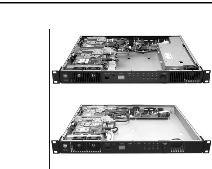
Figure 1.1 TB7100 base stations
Configuration with provision for internal AC power supply*
Configuration without provision for internal AC power supply* *cover removed

12 Introduction TB7100 Installation and Operation Manual
© Tait Electronics Limited December 2005
1.1 Frequency Bands
The base station is available in the following frequency bands:
■66 to 88MHz (A4)
■136 to 174MHz (B1)
■216 to 266 MHz (D1)
■400 to 470MHz (H5)
■450 to 530MHz (H6)
■450 to 520MHz (H7)
The RF band of the base station is implemented by the frequency band of
the transmitter and receiver modules.
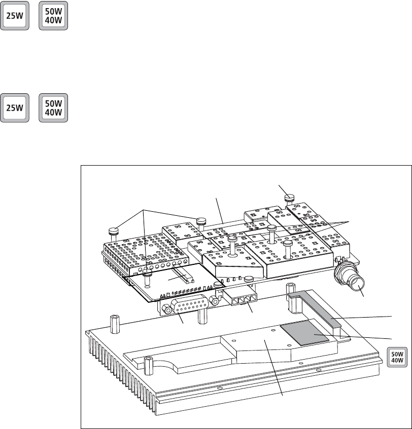
1.2 RF Output Power
The base station is available with 25W and 50W/40W RF output power.
The RF output power options are implemented by different transmitter and
receiver modules.
The 25W base station is available in the following frequency bands:
■A4
■B1
■D1
■H5
■H6
The 50W/40W base station is available in the following frequency bands:
■B1 (50W)
■H5 (40W)
■H7 (40W)

TB7100 Installation and Operation Manual Introduction 13
© Tait Electronics Limited December 2005
1.3 Power Supply Options
The base station is available with or without an internal AC power supply.
All base stations have an external DC input power connector which is used
as main power supply when no internal AC power supply is fitted.
When the internal AC power supply is fitted, the DC input can be used as
a DC backup power option. In case of AC mains failure the base station will
automatically and seamlessly switch to DC power input.
If no internal AC power supply is fitted, an external Tait T809-10-87xx
power supply can be used to supply the DC voltage required.
Warning!! The internal AC power supply unit contains
voltages that may be lethal. Refer to the ratings
label on the rear of the base station. The internal
AC power supply contains no user-servicable
parts.
Important Wrong mains voltage! Before connecting to the AC power
connector, ensure that the internal 115V/230V voltage
mains selector switch is set to the correct mains voltage.
1.4 Mechanical Configurations
The base station is available in two different mechanical configurations—
with or without provision for an internal AC power supply unit.
The mechanical configuration with provision for an internal AC power
supply has the following distinguishing features:
■larger air intake on the right-hand side of the front panel
■provision for AC connector on the left-hand side of the rear panel (refer
to Figure 1.1 on page 11)
■ground point on the right-hand side of the rear panel rather than on the
left-hand side
■different SI board and internal cables.
The mechanical configuration without provision for an internal AC power
supply unit cannot be upgraded with an internal AC power supply unit.
The product codes of the base station (see below) do not distinguish
between the mechanical configurations.
14 Introduction TB7100 Installation and Operation Manual
© Tait Electronics Limited December 2005
1.5 Product Codes
This section describes the product codes used to identify products of the
TB7100 base station product line.
The product codes of the TB7100 base station product line has the format:
TBBaabb-cde-ff
where:
■aa identifies the frequency band of the receiver:
A4=66 to 88MHz, B1=136 to 174MHz, D1=216 to 266 MHz,
H5=400 to 470MHz, H6=450 to 530MHz, H7=450 to 520MHz
■bb identifies the frequency band of the transmitter:
A4=66 to 88MHz, B1=136 to 174MHz, D1=216 to 266 MHz,
H5=400 to 470MHz, H6=450 to 530MHz, H7=450 to 520MHz
■c identifies the RF output power and digital architecture:
A=25W, level-1 digital architecture
B=35W to 50W, level-1 digital architecture
C=25W, level-2 digital architecture
D=35W to 50W, level-2 digital architecture
E=25W, level-3 digital architecture
F=35W to 50W, level-3 digital architecture
■d identifies the power supply option:
0=DC only
1=internal AC power supply unit, factory preset to 115VAC
2=internal AC power supply unit, factory preset to 230VAC
■e identifies the AC power cable:
1 = Australia/New Zealand
2 = United Kingdom
3 = Europe
4 = USA
■ff identifies base station options:
00=no options
TB7100 Installation and Operation Manual Mechanical Description 15
© Tait Electronics Limited December 2005
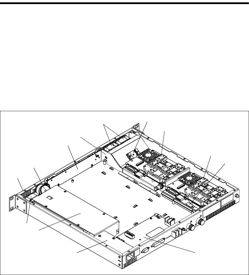
2 Mechanical Description
Overview The base station consists of the following main modules:
■tray b
■UI board (user interface) d
■receiver module h
■transmitter module i
■SI board (system interface) 1)
■internal AC power supply unit 1@ (if fitted).
All modules and boards are mounted from above into the 1U tray b.
The modules are secured by screws or clips into standoffs on the tray chassis,
and are easily removed for replacement.
The base station includes two cooling fans f and a fan duct e in front of
the receiver and transmitter modules, a speaker c mounted behind the front
panel, a fan power board g mounted on the fan duct, and a temperature
sensor board j mounted on the heatsink of the transmitter module i.
If the internal AC power supply unit 1@ is fitted, the base station includes an
additional fan 1# and an AC filter module 1!.
The modules and components are interconnected by looms and cables.
Figure 2.1 Parts of the base station (configuration with internal AC power supply unit shown)
1!
g
i
1)
b
c
d
f
e
h
j
1@
1#
16 Mechanical Description TB7100 Installation and Operation Manual
© Tait Electronics Limited December 2005
2.1 Tray
The 1U tray consists of a mild steel folded chassis and a flat cover (not
shown) which is fastened to the chassis with 15 Torx T10 screws. The tray
can be fitted into a standard 19 inch rack or cabinet using the two rack
mounting brackets.
The front panel has holes to accommodate the controls and the
microphone/programming connector of the UI board.
The rear panel has holes to accommodate the connectors and the fuse holder
of the SI board, the antenna connectors, and a ground terminal.
For more information on the connections, refer to “Connections” on
page 65.
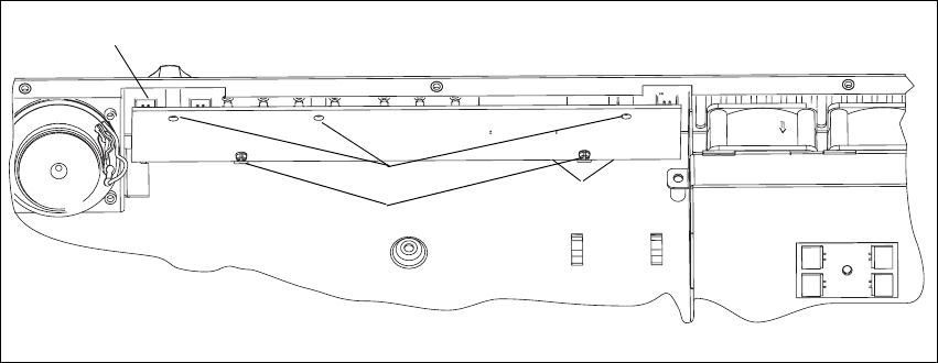
2.2 UI Board
The UI board is mounted behind the front panel with three Torx T10
screws c and two spring clips D. The UI board is connected to the
transmitter and receiver modules via the two Micro-MaTch connectors e
and the two UI cables (not shown). The UI board also has a speaker
connector b.
A volume knob is fitted to the shaft of the volume-control potentiometer.
Figure 2.2 UI board
e
d
c
b
Cables not shown.
TB7100 Installation and Operation Manual Mechanical Description 17
© Tait Electronics Limited December 2005
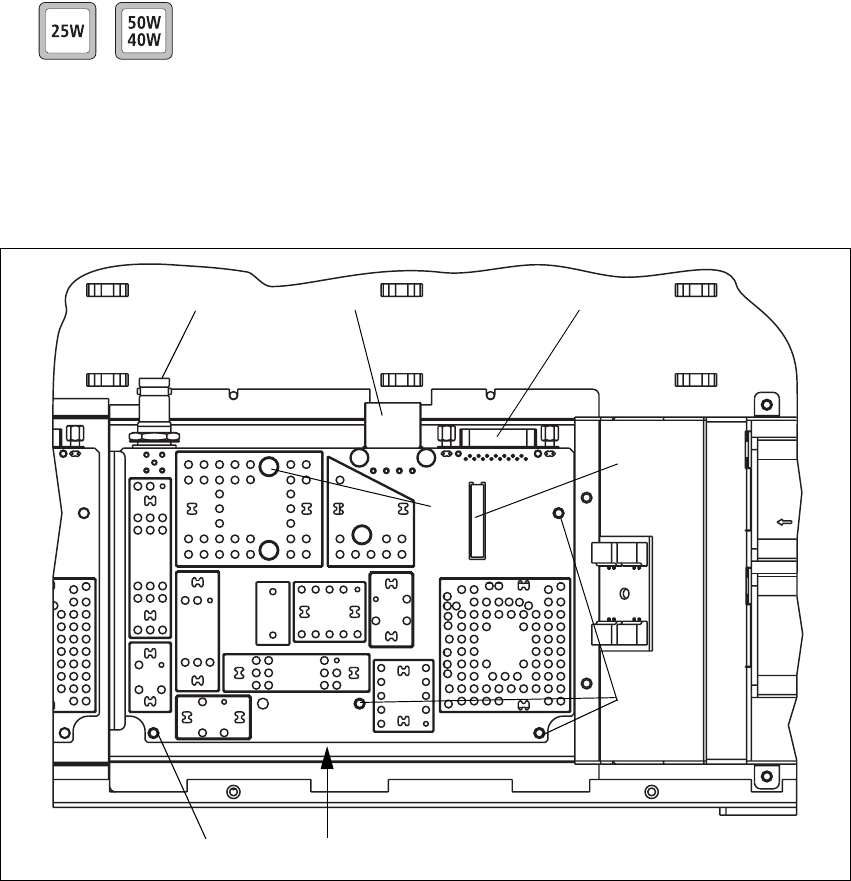
2.3 Receiver Module
The receiver module is mounted in the front left of the tray with five Torx
T10 screws g.
The receiver module is a printed circuit board in SMT design with
components on the top and bottom sides. A digital board is reflow-soldered
to the receiver. Most components are shielded by metal cans.
There are different boards for each frequency band and each RF output
power configuration.
The RF b, DC power c, auxiliary d, and user interface f connectors are
located on the bottom side of the board. The internal options connector e
and a factory connector (not shown) for factory use are located on the top
side of the board.
For compliance reasons, there are different variants of the receiver module
for use in the 25W and 50W/40W base stations. The 25W version has a
white DC power connector C and the 50W/40W version has a black DC
power connector.
For more information on the connectors, refer to “Connections” on
page 65.
Figure 2.3 Receiver module
g
g
f
bcd
g
e
18 Mechanical Description TB7100 Installation and Operation Manual
© Tait Electronics Limited December 2005
2.4 Transmitter Module
The transmitter module consisting of a transmitter board f mounted on a
purpose-designed heatsink 1) is mounted in the left rear of the tray with
four Torx T10 screws (not shown).
The transmitter board is a printed circuit board in SMT design with
components on the top and bottom sides. A digital board is reflow-soldered
to the board. Most components are shielded by metal cans. There are
different boards for each frequency band and each RF output power
configuration.
The RF b, DC power c, auxiliary d, and user interface f connectors are
located on the bottom side of the board. The internal options connector e
and a factory connector (not shown) for factory use are located on the top
side of the board.
The 50W/40W version has a black DC power connector C and the 25W
version has a white DC power connector. For more information on the
connectors, refer to “Connections” on page 65.
The board f is mounted to the heatsink 1) with seven Torx T10 screws
fand g.
An L-shaped gap pad i and (with the 50W/40W version) a rectangular gap
pad j are fitted between the board f and the heatsink 1) to improve heat
transfer.
Figure 2.4 Transmitter module
g
h
g
c
f
1)
D
b
e
j
i
TB7100 Installation and Operation Manual Mechanical Description 19
© Tait Electronics Limited December 2005
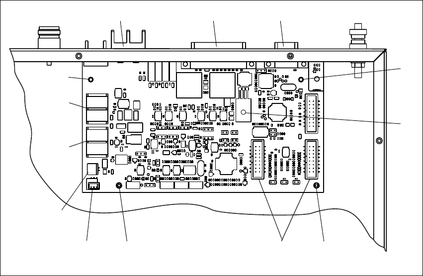
2.5 SI Board
The SI board is mounted in the rear right of the tray with two Torx T10
screws 1), one Pozidriv screw j, and two spring clips 1!.
The SI board has the following external connectors:
■13.8V DC power connector (labelled 12V DC) b
■system connector (labelled SYSTEM) c
■serial data connector (labelled IOIOI) D.
The SI board has the following internal connectors:
■two system interface connectors e (to transmitter and receiver)
■one DC input connector h, if fitted (from internal AC power supply)
■one DC output connector i (to transmitter and receiver)
■fan control connector f (to fan power board on fan duct)
■temperature control connector g (to temperature sensor on transmitter
heatsink).
For more information on the connectors, refer to “Connections” on
page 65.
Figure 2.5 SI board
g
i
bc d
1) 1)
j
1!1! ef
h
20 Mechanical Description TB7100 Installation and Operation Manual
© Tait Electronics Limited December 2005
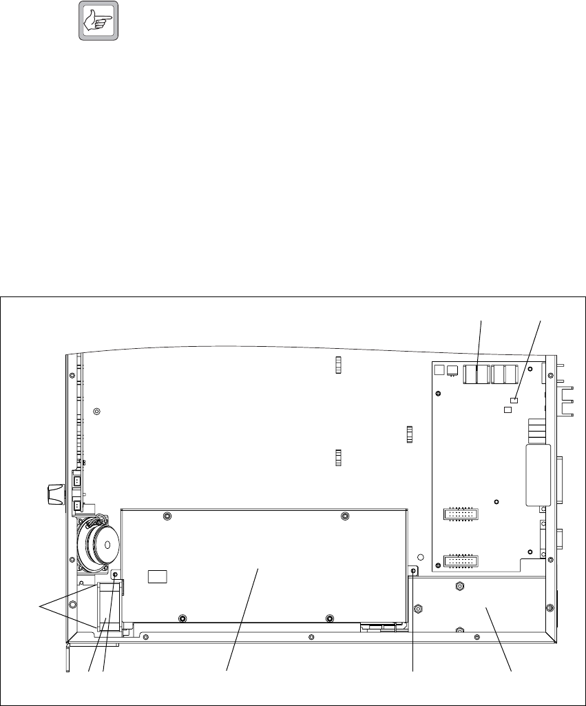
2.6 AC Power Supply Unit
The base station may be fitted with an internal AC power supply unit f, an
AC filter module d, and an additional fan g.
The AC filter module has a standard AC connector that fits into a provision
on the rear of the tray. The AC filter module slides into securing tabs on the
tray floor and is held in place by the AC power supply unit.
Note Mechanical configurations without the provision for a standard
AC connector cannot be upgraded with the internal AC power
supply unit.
The AC power supply unit is held in place by two screws e. The fan is
attached to the AC power supply unit by two screws h.
The AC power supply unit is connected to the AC filter module via a cable
connector (not shown).
The DC output of the AC power supply unit is connected to the SI board
b. The AC power supply unit also has a cable to provide a mains failure
signal to the SI board c. In case of a mains failure, this signal will cause the
power circuitry on the SI board to switch to DC external input.
Figure 2.6 AC power supply unit, filter module and fan
h
e dfe
bc
g
TB7100 Installation and Operation Manual Functional Description 21
© Tait Electronics Limited December 2005
3 Functional Description
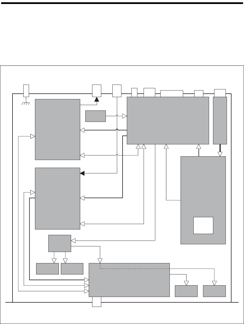
This section describes some principles of the base station operation.
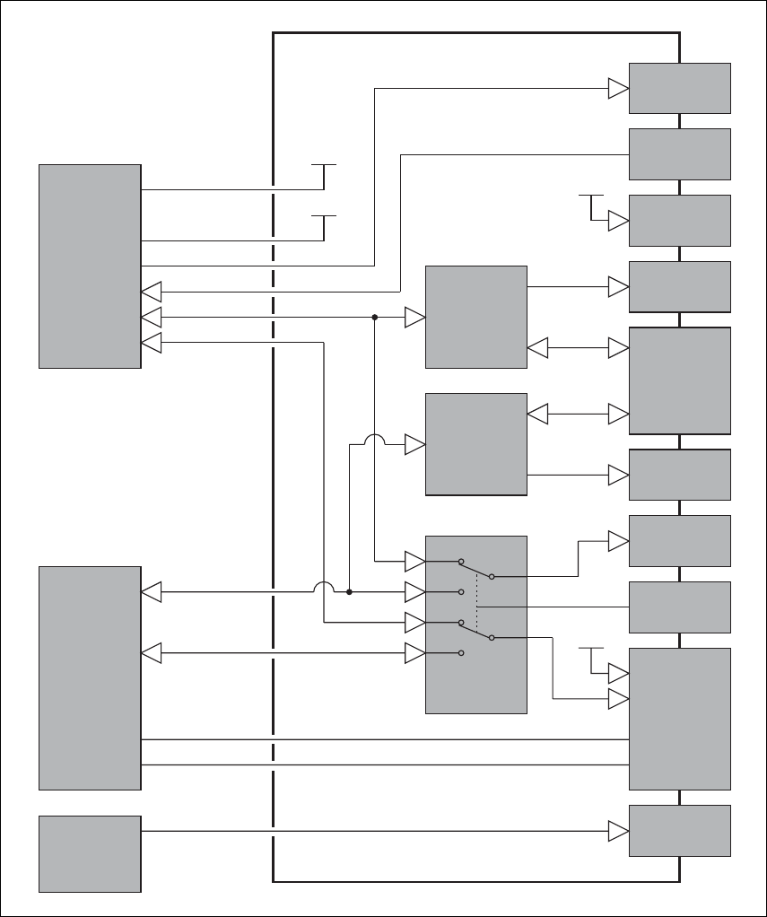
Figure 3.1 shows the high-level block diagram of the base station.
Figure 3.1 Base station high-level block diagram
DC Input
Connector System
Connector Serial Data
Connector AC Input
Connector
Rx
Connector
Tx/Ant
Connector
Ground
Point
Transmitter
Module
Receiver
Module
UI Board
AC
Power Supply
Unit
Fan
FanFan
Fan Power
Board
Speaker
Temperature
Sensor
Prog/Mic
Connector
Receiver/SI
Internal power
RF
Transmitter/SI
Internal power
RF
UI/Receiver
Internal power
UI/Transmitter
Internal power
AC Input Filter
Module
115V/230V
Selector
Switch
SI Board
Fuse
Mains fail signal
22 Functional Description TB7100 Installation and Operation Manual
© Tait Electronics Limited December 2005
The block diagram illustrates the main inputs and outputs for power, RF
and control signals, as well as the interconnection between modules:
■program data and audio from the PROG/MIC socket on the UI board to and
from the transmitter and receiver modules
■audio and signalling from the SYSTEM connector to and from the
transmitter and receiver modules
■RS-232 data from the serial data connector (IOIOI) to and from the
transmitter and receiver modules
■fan power and control from the SI board
■power distribution from the AC and DC power input connectors to the
transmitter and receiver modules, and from the receiver module to the
UI board.
The circuitry of the individual modules that make up the base station is
described in more detail in the following sections.
Frequency Bands
and Sub-bands The circuitry of the transmitter and receiver modules is similar for all
frequency bands and is therefore covered by a single description in this
manual. Where the circuitry differs between bands, separate descriptions are
provided for each frequency band. For more information on frequency
bands, refer to the specifications manual.
RS-232 Signals External data communications all occur directly between the connected
computer (or other electrical equipment) and the transmitter and receiver
modules over the RS-232 serial lines.
Fan Signals The power and ground signals for the fans are routed from the SI board to
the fans behind the front panel. These signals are electrically isolated from
all other system signals to ensure fan noise is not transferred to other sensitive
system components.
If there is a fault in the fan circuitry, the transmitter module is protected from
overheating by its internal foldback circuitry.
Speaker Signal Received audio is sent from the receiver module to the UI board.
The volume is controlled by the volume potentiometer on the UI board.
The audio signal is routed through the UI board to the speaker for
monitoring purposes.
Power and Ground The SI board provides power to the transmitter and receiver modules.
The receiver modules provides power to the UI board.
TB7100 Installation and Operation Manual Functional Description 23
© Tait Electronics Limited December 2005
3.1 Receiver Operation
Parts of Receiver
Board The main circuit parts of the receiver modules are:
■receiver
■frequency synthesizer
■CODEC (coder-decoder) and audio circuitry
■power supply
■interface circuitry
Software plays a prominent role in the functioning of the radio.
When describing the operation of the radio the software must be included
with the above. This is considered further below.
These functional parts are described in detail below.
3.1.1 RF Hardware
Front End Circuitry
and First IF The front-end hardware amplifies and image filters the received RF
spectrum, then down-converts the desired channel frequency to a first
intermediate frequency IF1 of 45.1MHz (UHF) or 21.4MHz (VHF) where
coarse channel filtering is performed. The first LO (local oscillator) signal is
obtained from the frequency synthesizer and is injected on the low side of
the desired channel frequency for all bands except A4. When receiving the
modulation to the frequency synthesizer is muted. The output of the first IF
(intermediate frequency) stage is then down-converted using an image-
reject mixer to a low IF of 64kHz.
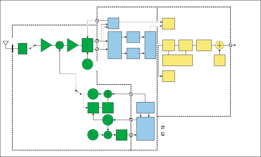
Figure 3.2 Receiver high-level block diagram
IF:
UHF: 45.1 MHz
VHF: 21.4 MHz
Digital
down-
converter
Squelch
Front
end
1st
IF
Channel
LPF
Channel
LPF
RSSI
Second LO
UHF: 90.328 MHz
VHF: 42.928 MHz
FM
Demod
Quad
Demod
RX
AGC
Analogue-to-digital conversion
2nd IF:
64 kHz
Audio
filtering
De-
emphasis
Optional
processing
Data and signalling
decoders
Side
tones
System Interface
or User Interface
Phase
locked to
TCXO
LPF
ANT
Mag.
PLL
Loop
filter
Loop
filter
Frequency
control
Triple-point
Equalisation
TCXO:
13.000 MHz
VCO
VCXO
CUSTOM-
LOGIC
BLOCK
HARDWARE BLOCK
Digital-to-analogue conversion
KEY
NOTES
(1) Noise blanker not shown
DSP
BLOCK
24 Functional Description TB7100 Installation and Operation Manual
© Tait Electronics Limited December 2005
Quadrature
Demodulator The LO for the image-reject mixer (quadrature demodulator) is synthesized
and uses the TCXO (temperature-compensated crystal oscillator) as a
reference. This ensures good centring of the IF filters and more consistent
group-delay performance. The quadrature demodulator device has an
internal frequency division of 2 so the second LO operates at
2x(IF1 + 64kHz). The quadrature output from this mixer is fed to a pair
of ADCs (analog-to-digital converters) with high dynamic range where it is
oversampled at 256kHz and fed to the custom logic device.
Automatic Gain
Control The AGC (automatic gain control) is used to limit the maximum signal level
applied to the image-reject mixer and ADCs in order to meet the
requirements for intermodulation and selectivity performance. Hardware
gain control is performed by a variable-gain amplifier within the quadrature
demodulator device driven by a 10-bit DAC (digital-to-analog converter).
Information about the signal level is obtained from the IQ (in-phase and
quadrature) data output stream from the ADCs. The control loop is
completed within custom logic. The AGC will begin to reduce gain when
the combined signal power of the wanted signal and first adjacent channels
is greater than about –70dBm. In the presence of a strong adjacent-channel
signal it is therefore possible that the AGC may start acting when the wanted
signal is well below –70dBm.
3.1.2 Digital Baseband Processing
Custom Logic The remainder of the receiver processing up to demodulation is performed
by custom logic. The digitised quadrature signal from the RF hardware is
digitally down-converted to a zero IF, and channel filtering is performed at
base-band. Different filter shapes are possible to accommodate the various
channel spacings and data requirements. These filters provide the bulk of
adjacent channel selectivity for narrow-band operation. The filters have
linear phase response so that good group-delay performance for data is
achieved. The filters also decimate the sample rate down to 48kHz. Custom
logic also performs demodulation, which is multiplexed along with AGC
and amplitude data, and fed via a single synchronous serial port to the DSP.
The stream is demultiplexed and the demodulation data used as an input for
further audio processing.
Noise Squelch The noise squelch process resides in the DSP. The noise content above and
adjacent to the voice band is measured and compared with a preset
threshold. When a wanted signal is present, out-of-band noise content is
reduced and, if below the preset threshold, is indicated as a valid wanted
signal.
Received Signal
Strength Indication Received signal strength is measured by a process resident in the DSP.
This process obtains its input from the demodulator (value of RF signal
magnitude) and from the AGC (value of present gain). With these two
inputs and a calibration factor, the RF signal strength at the antenna can be
accurately calculated.
TB7100 Installation and Operation Manual Functional Description 25
© Tait Electronics Limited December 2005
Calibration The following items within the receiver path are calibrated in the Factory:
■front-end tuning
■AGC
■noise squelch
■RSSI (received signal strength indication)
Information on the calibration of these items is given in the on-line help
facility of the calibration application.
3.1.3 Audio Processing and Signalling
Audio Processing Raw demodulated data from the receiver is processed within the DSP. The
sample rate at this point is 48kHz with signal bandwidth limited only by the
IF filtering. Scaling (dependent on the bandwidth of the RF channel) is then
applied to normalise the signal level for the remaining audio processing.
The sample rate is decimated to 8kHz and bandpass audio filtering (0.3 to
3kHz) is applied. The base station takes the audio from the receiver mode
at Tap R4 by default; this point has no de-emphasis. This tap point can be
changed if required, for example, for trunking applications.
Data and Signalling
Decoders The data and signalling decoders obtain their signals from various points
within the audio processing chain. The point used depends on the
bandwidth of the decoders and whether de-emphasis is required. Several
decoders may be active simultaneously.
Side Tones Side tones are summed in at the end of the audio-processing chain.
These are tones that provide some form of alert or give the user confidence
an action has been performed. The confidence tones may be generated in
the receiver. The side-tone level is a fixed proportion (in the order of
–10dB) relative to full scale in the receive path. By default, all audible
indicators are turned off.
CODEC The combined audio and side-tone signal is converted to analog form by a
16-bit DAC with integral anti-alias filtering. This is followed by a
programmable-gain amplifier with a range of 45dB in 1.5dB steps.
The amplifier performs muting. The DAC is part of the same CODEC
device (AD6521).
Output to Speakers The output of the CODEC is fed to an audio power amplifier and to the
UI board via a buffer amplifier. The output configuration of the audio
power amplifier is balanced and drives an internal speaker. The power
delivered to the speaker is limited by its impedance. The speaker has 16Ω
impedance.
26 Functional Description TB7100 Installation and Operation Manual
© Tait Electronics Limited December 2005
3.2 Transmitter Operation
Parts of Transmitter
Board The main circuit parts of the transmitter board are:
■transmitter
■frequency synthesizer
■CODEC (coder-decoder) and audio circuitry
■power supply
■interface circuitry
Software plays a prominent role in the functioning of the board.
When describing the operation of the radio the software must be included
with the above. This is considered further below.
These functional parts are described in detail below.
3.2.1 Audio Processing and Signalling
Microphone Input The input to the transmitter path begins at either the SI board or the
PROG/MIC connector of the UI board. Only electret-type microphones are
supported. The audio input is then applied to tap point T8 on the
transmitter board (the tap point is user-selectable).
Analog Processing
of Microphone
Signal
The CODEC (AD6521) performs microphone selection and amplification.
The microphone amplifier consists of an amplifier with a fixed gain of 16dB
followed by a programmable-gain amplifier with 0dB to 22dB gain.
The amplified microphone signal is converted to a digital stream by a 16-bit
ADC with integral anti-alias filtering (0.1 to 3.2kHz). The digital stream is
transported to the DSP for further audio processing.
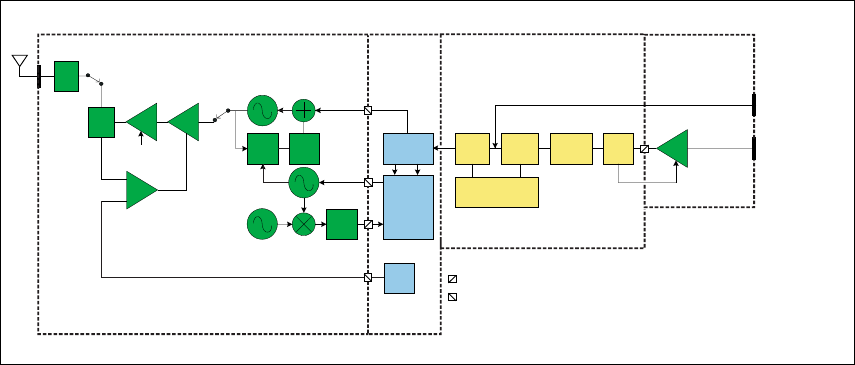
Figure 3.3 Transmitter high-level block diagram
Analog-to-digital conversion
LPF
ANT
PLL
Loop
filter
Loop
filter
Frequency
control
Triple-point
Equalisation
Audio
filtering
Pre-
emphasis
Optional
processing
Data and signalling
encoders
ALC Mic
PGA
Dir.
Coup. Fin Drv
/Ex
Pwr
Crtl
Ramp
control
TCXO:
13.000 MHz
VCO
VCXO
Bias
CUSTOM
LOGIC
BLOCK
HARDWARE
BLOCK
HARDWARE BLOCK
Digital-to-analog conversion
KEY
PROG/MIC connector
DSP
BLOCK
SYSTEM connector
Tap point T8
TB7100 Installation and Operation Manual Functional Description 27
© Tait Electronics Limited December 2005
Automatic Level
Control The ALC (automatic level control) follows, and is used to effectively increase
dynamic range by boosting the gain of the microphone pre-amplifier under
quiet conditions and reducing the gain under noisy acoustic conditions.
The ALC function resides in the DSP and controls the microphone
programmable-gain amplifier in the CODEC. The ALC has a fast-attack
(about 10ms) and slow-decay (up to 2s) characteristic. This characteristic
ensures that the peak signal level is regulated near full scale to maximise
dynamic range.
DSP Audio
Processing The output of the automatic level control provides the input to the DSP
audio-processing chain at a sample rate of 8kHz. Optional processing such
as encryption or companding is done first if applicable. Pre-emphasis, if
required, is then applied. The pre-emphasised signal is hard limited to
prevent over deviation, and filtered to remove high-frequency components.
The sample rate is then interpolated up to 48kHz and scaled to be suitable
for the frequency synthesizer.
Data and Signalling
Encoders The data and signalling encoders inject their signals into various points
within the audio-processing chain. The injection point depends on the
bandwidth of the encoders and whether pre-emphasis is required.
3.2.2 Frequency Synthesizer
Main Parts of
Synthesizer The frequency synthesizer consists of two main parts:
■FCL (frequency control loop)
■RF PLL (phase-locked loop)
The FCL and RF PLL are described briefly below. Note that patents are
pending for several aspects of the synthesizer design.
Frequency Control
Loop The FCL consists of the following:
■TCXO
■mixer
■loop filter
■VCXO (voltage-controlled crystal oscillator)
■frequency control block
The FCL provides the reference frequency for the RF PLL. It generates a
high-stability reference frequency that can be both modulated and offset in
fine resolution steps.
28 Functional Description TB7100 Installation and Operation Manual
© Tait Electronics Limited December 2005
RF PLL The RF PLL consists of the following:
■RF PLL device
■loop filter
■VCO (voltage-controlled oscillator)
■VCO output switch
The RF PLL has fast-locking capability but coarse frequency resolution.
The above combination of control loops creates improved frequency
generation and acquisition capabilities.
Operation of
Control Loop The RF PLL is a conventional integer-N design with frequency resolution
of 25kHz. In transmit mode the loop locks to the transmit frequency.
Initially, the VCO generates an unregulated frequency in the required range.
This is fed to the PLL device (ADF4111) and divided down by a
programmed ratio to approximately 25kHz. The reference frequency input
from the FCL is also divided down to approximately 25kHz. The phase of
the two signals is compared and the error translated into a DC voltage by a
programmable charge pump and dual-bandwidth loop filter. This DC signal
is used to control the VCO frequency and reduce the initial error. The loop
eventually settles to a point that minimises the phase error between divided-
down reference and VCO frequencies. The net result is that the loop locks
to a programmed multiple of the reference frequency.
The FCL generates an output of 13.012±0.004MHz. Initially a VCXO
produces a quasi-regulated frequency in the required range. The VCXO
output is fed to a mixer where it is mixed with the 13.000MHz TCXO
frequency. The mixer, after low-pass filtering to remove unwanted products,
produces a nominal frequency of 12kHz. This is converted to digital form
and transported to the frequency-control block in custom logic.
The frequency-control block compares the mixer output frequency with a
reference generated by the digital clock and creates a DC error signal. A
programmed offset is also added. This error signal is converted to analog
form and used to control the VCXO frequency and reduce the initial error.
Once settled, the loop locks to the TCXO frequency with a programmed
offset frequency. The FCL output therefore acquires the TCXO’s frequency
stability.
Modulation The full bandwidth modulation signal is obtained from the DSP in digital
form at a sample rate of 48kHz. In traditional dual-point modulation
systems the modulation is applied, in analog form, to both the frequency
reference and the VCO in the RF PLL, combining to produce a flat
modulation response down to DC. Reference modulation is usually applied
directly to the TCXO.
TB7100 Installation and Operation Manual Functional Description 29
© Tait Electronics Limited December 2005
In the system employed in the transmitter board, the frequency reference is
generated by the FCL, which itself requires dual-point modulation injection
to allow modulation down to DC. With another modulation point required
in the RF PLL, this system therefore requires triple-point modulation.
The modulation signals applied to the FCL are in digital form, whereas for
the RF PLL (VCO) the modulation signal is applied in analog form.
The modulation cross-over points occur at approximately 30 and 300Hz as
determined by the closed loop bandwidths of the FCL and RF PLL
respectively.
Frequency
Generation The RF PLL has a frequency resolution of 25kHz. Higher resolution cannot
be achieved owing to acquisition-time requirements and so for any given
frequency the error could be as high as ±12.5kHz. This error is corrected
by altering the reference frequency to the RF PLL. The FCL supplies the
reference frequency and is able to adjust it up to ±300ppm with better than
0.1ppm resolution (equivalent to better than 50Hz resolution at the RF
frequency).
Fast Frequency
Settling Both the FCL and RF PLL employ frequency-acquisition speed-up
techniques to achieve fast frequency settling. The frequency-acquisition
process of the FCL and RF PLL is able to occur concurrently with minimal
loop interaction owing to the very large difference in frequency step size
between the loops.
Frequency
Acquisition
of RF PLL
In the RF PLL the loop bandwidth is initially set high by increasing the
charge pump current and reducing time constants in the loop filter. As a
result settling to within 1kHz of the final value occurs in under 4ms. In
order to meet noise performance requirements the loop parameters are then
switched to reduce the loop bandwidth. There is a small frequency kick as
the loop bandwidth is reduced. Total settling time is under 4.5ms.
Frequency
Acquisition
of FCL
The FCL utilises self-calibration techniques that enable it to rapidly settle
close to the final value while the loop is open. The loop is then closed and
settling to the final value occurs with an associated reduction in noise.
The total settling time is typically less than 4 ms.
Calibration The following items are calibrated in the frequency synthesizer:
■nominal frequency
■KVCO
■KVCXO
■VCO deviation
Calibration of the nominal frequency is achieved by adding a fixed offset to
the FCL nominal frequency; the TCXO frequency itself is not adjusted.
The items KVCO and KVCXO are the control sensitivities of the RF VCO
(in MHz/V) and VCXO (in kHz/V) respectively. The latter has temperature
compensation.

30 Functional Description TB7100 Installation and Operation Manual
© Tait Electronics Limited December 2005
3.2.3 RF Power Amplifier
RF Power Amplifier
and Switching
(50W/40W Version)
The RF power amplifier and exciter of the 50W/40W radio is a five-stage
line-up with approximately 40dB of power gain. The output of the
frequency synthesizer is first buffered to reduce kick during power ramping.
The buffer output goes to a discrete exciter that produces approximately 300
to 400mW output. This is followed by an LDMOS driver producing up to
8W output that is power-controlled. The final stage consists of two parallel
LDMOS devices producing enough power to provide 40 to 50W at the RF
connector.
RF Power Amplifier
and Switching
(25W Version)
The RF power amplifier of the 25W version is a four-stage line-up with
approximately 37dB of power gain. The output of the frequency synthesizer
is first buffered to reduce kick during power ramping. The buffer output
goes to a broad-band exciter IC that produces approximately 200mW
output. This is followed by an LDMOS driver producing up to 2W output
that is power-controlled. The final stage consists of two parallel LDMOS
devices producing enough power to provide 25W at the RF connector.
Output of RF
Power Amplifier The output of the RF PA passes through a dual-directional coupler, used for
power control and monitoring. Finally, the output is low-pass-filtered to
bring harmonic levels within specification.
Power Control The steady-state power output of the transmitter is regulated using a
hardware control loop. The forward power output from the RF PA is sensed
by the directional coupler and fed back to the power control loop. The PA
output power is controlled by varying the driver gate bias voltage that has a
calibrated maximum limit to prevent overdrive. The power control signal is
supplied by a 13-bit DAC driven by custom logic.
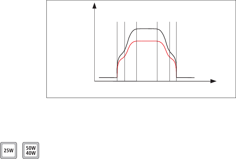
Ramping Power ramp-up consists of two stages:
■bias
■power ramping
The timing between these two stages is critical to achieving the correct
overall wave shape in order to meet the specification for transient ACP
(adjacent channel power). A typical ramping waveform is shown in
Figure 3.4.
TB7100 Installation and Operation Manual Functional Description 31
© Tait Electronics Limited December 2005
Bias Ramp-up The steady-state final-stage bias level is supplied by an 8-bit DAC
programmed prior to ramp-up but held to zero by a switch on the DAC
output under the control of a TX INHIBIT signal. Bias ramp-up begins upon
release by the TX INHIBIT signal with the ramping shape being determined by
a low-pass filter. Owing to power leakage through the PA chain, ramping
the bias takes the PA output power from less than –20dBm for the
50W/40W version or –10dBm for the 25W version to approximately
25dB below steady-state power.
Power Ramp-up The power ramp signal is supplied by a 13-bit DAC that is controlled by
custom logic. The ramp is generated using a look-up table in custom logic
memory that is played back at the correct rate to the DAC to produce the
desired waveform. The ramp-up and ramp-down waveforms are produced
by playing back the look-up table in forward and reverse order respectively.
For a given power level the look-up table values are scaled by a steady-state
power constant so that the ramp waveform shape remains the same for all
power levels.
Figure 3.4 Typical ramping waveforms
Power
ramp
High power
powerLow
Power
Time
Bias
ramp
Bias
ramp Power
ramp
32 Functional Description TB7100 Installation and Operation Manual
© Tait Electronics Limited December 2005
3.3 User Interface Operation
This section describes the programming/microphone connector and the
controls of the user interface, and the function of the UI board.
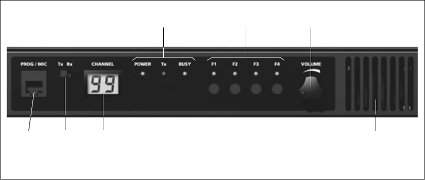
Figure 3.5 shows the controls and indicators of the user interface.
Programming/
Microphone
Connector
The PROG/MIC connector can be used to connect a handset or a programming
cable.
TX/RX Switch The TX/RX switch changes the LCD display to show either the transmitter or
the receiver channel. The TX/RX switch also determines which board will be
programmed by the programming or calibration applications.
The programming application is a program on a PC that is connected to the
base station via the PROG/MIC connector. The programming application
enables the user to program the base station with the required channels and
subaudible signalling settings. The transmitter and receiver modules are
programmed individually according to the setting of the TX/RX switch.
The calibration application is a program on a PC that is connected to the
base station via the PROG/MIC connector. The transmitter and receiver
modules are designed to be totally electronically tuned. No physical tuning
is required, as all tuning is done by electronic trimming. The calibration
application can assist in the tuning of:
■AD6521 CODEC voltage reference
■TCXO frequency
■receiver front end
■transmitter driver and final gate bias limit
■transmitter power control
■deviation and squelch.
Figure 3.5 User interface
volume controlfunction keys and LEDs
internal speaker
status LEDs
2-digit LCD
display
Tx/Rx
switch
programming/
microphone
connector
TB7100 Installation and Operation Manual Functional Description 33
© Tait Electronics Limited December 2005
Function Keys Pressing the function keys will activate the functions assigned using the
programming application. Function keys may have functions assigned to
both short and long key presses. A short key press is less than one second,
and a long key press is more than one second.
Volume Control and
Internal Speaker Rotate the volume control potentiometer clockwise to increase the speaker
volume and counterclockwise to decrease the volume. By default, the base
station is programmed not to generate any audible indicators.
UI Board The UI board is connected to the receiver and transmitter modules via
separate 18-way ribbon cables. The internal speaker is connected to the
UI board via a cable with a mating connector for easy disconnection.
If an internal AC Power supply is fitted, a fan power signal is routed from
the fan power board to the fan via the UI board. For more information on
the connectors and their signals, refer to “UI Board Connectors” on
page 75.
Figure 3.6 on page 34 shows a block diagram of the UI board.
The UI board does not include a microprocessor. A synchronous bi-
directional serial interface provides communication of key status, LCD and
LED-indicator data between the transmitter/receiver modules and the UI
board. The serial data is converted to or from a parallel form by a number
of shift registers for the function keys and indicators. For the LCD, the serial
data is fed to a driver IC that converts the serial data to a form suitable for
the LCD. The keys are scanned and the LCD and LED indicators updated
approximately every 50ms. The TX/RX switch controls what is displayed on
the LCD and also whether the transmitter module or the receiver module
will be programmed.
34 Functional Description TB7100 Installation and Operation Manual
© Tait Electronics Limited December 2005
Figure 3.6 UI board block diagram
Receiver
Module
+13V8
+3V3
SpeakerAudio
Volume Level (DC)
Rx SPI Data
Rx Prog Data
Receiver
SPI Shift
Registers
+13V8
+3V3
Transmitter
SPI Shift
Registers
Transmitter
Module Electronic
Switching
Rx SPI Data
Rx Prog Data
Speaker
Function
Keys and
LEDs
Volume
Control
Power
LED
Busy
LED
Tx
LED
LCD
Tx/Rx
Switch
Prog/Mic
Connector
Fan
Connector
+13V8
PTT
MicAudio
Fan Power
Board
Fan Power
+3V3
UI Board
TB7100 Installation and Operation Manual Functional Description 35
© Tait Electronics Limited December 2005
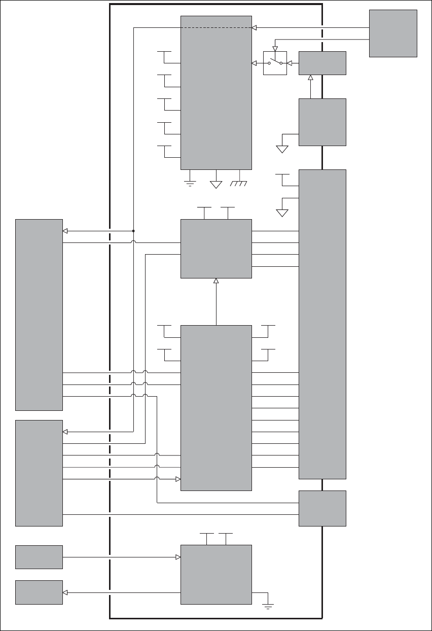
3.4 System Interface Operation
This section describes the functioning of the system interface. The system
interface provides:
■internal power distribution
■internal AC/external DC switching
■serial data connection (THSD or FFSK)
■fan control
■general purpose IO
■receiver audio processing
■transmitter audio processing
■opto-isolated keying
■relay output
■received signal strength indication (RSSI)
■receiver gate output
■receiver inhibit input
■13.8VDC (1.5A) output
■tone on idle (TOI).
These functional parts are described in detail below.
36 Functional Description TB7100 Installation and Operation Manual
© Tait Electronics Limited December 2005
Figure 3.7 SI board block diagram
13.8V
9V
4.5V
3.3V
13.8V out
Power Supplies
9V 4.5V
RXAUDIO OUT
RX LINE OUT
TX INAUDIO
TX LINE IN
TOITONE
AUD IN
13.8V
13.8V
9V
4.5V
3.3V
Audio
Control
and
Signalling
AUX IO
TX KEY
TX DATA
AUX IO
RX GATE
RSSI
RX DATA
AUD OUT
Transmitter
Module
Receiver
Module
Temperature
Sensor
Fan Power
Board
Fan Control
Serial Data
Connector
RXD
TXD
13.8V out
System
Connector
13.8V 3.3V
RSSI
RX GATE
DIG IO
OPTO
RELAY DRIVER
RX INHIBIT
TX KEY
TX DIG IO
RX DIG IO
DC Power
Connector
Mains fail signal
13.8V
AC Power
Supply Unit
Fuse
13.8V
13.8V
AGND IN
SI Board
TB7100 Installation and Operation Manual Functional Description 37
© Tait Electronics Limited December 2005
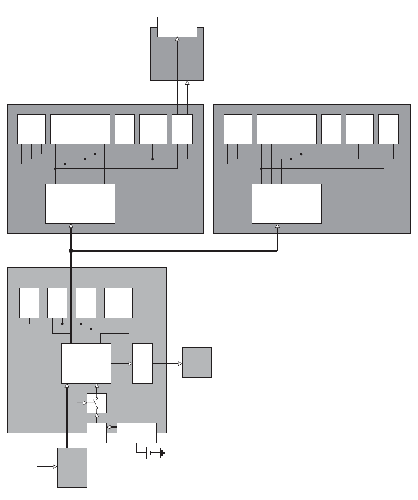
3.4.1 Internal Power Distribution
This section details how the input power feed is distributed throughout the
base station to power its various sub-systems. Refer to Figure 3.8 for more
information.
13.8V DC This is from either the DC input on the rear of the base station, or from an
optional internal AC power supply unit. When AC mains is present, power
will not be drawn from the DC input. The DC power input of the base
station is protected by a rear panel fuse. The 13.8V is distributed directly to
Figure 3.8 Power distribution
Data
Circuitry
Control
Circuitry
Audio
Circuitry
CWID
Power
Supply
Circuitry
Fan Control
Circuitry
AC Power
Supply Unit Mains fail signal
DC
Power
Source
13.8V
Fuse
DC Power
Connector
SI Board
Fan
Power
Board
Receiver
Module
4.5V
3.3V
9V
13.8V Power
Supply
Circuitry
13.8V
9V
6V
3.3V
Frequency
Synthesizer
CODEC
andAudio
Receiver
Digital
Board
Interface
3V
2.5V
Transmitter
Module
Power
Supply
Circuitry
13.8V
9V
6V
3.3V
Frequency
Synthesizer
CODEC
andAudio
Transmitter
Digital
Board
Interface
3V
2.5V
Prog/Mic
Connector
UI Board
AC
Power
Source

38 Functional Description TB7100 Installation and Operation Manual
© Tait Electronics Limited December 2005
the receiver and transmitter boards and to the 13.8VDC output on the
SYSTEM connector, rated at 1.5A. The 13.8VDC is also used to power the
fans, via control circuitry.
Note The UI board obtains 13.8V and 3.3V from the receiver module
and outputs 13V8_SW to the PROG/MIC connector.
3.3V, 4.5V, 9V, 13.8V The other voltages derived on the SI board are used only on the SI board.
3.4.2 Serial Data
THSD Tait High Speed Data (THSD) is a proprietary protocol of Tait Electronics
Limited that can be used with the base station. This allows the base station
configured in either data repeater or data modem modes to pass data speeds
up to 12kbps on a narrow-band channel and 19.2kbps on a wide-band
channel. 1200-baud Fast Frequency Shift Keyed (FFSK) data is also available
as an option.
3.4.3 General Purpose IO
The transmitter and receiver boards can be programmed to act upon signals
from the SI board and also outputs signals for certain conditions.
These settings are discussed in “Preparation for Operation” on page 77.
3.4.4 Receiver Audio Processing
The SI board provides an external 600Ω balanced 4-wire line for connecting
4-wire circuits of which two are used by the receiver for receive audio.
The SI board provides an unbalanced audio output for connecting to other
devices. Output levels can be set via the rear panel.
3.4.5 Tone On Idle
The tone-on-idle (TOI) frequency is generated by the SI board and fed
directly to the receiver line out. It is enabled using links on the SI board.
These settings are discussed in “Preparation for Operation” on page 77.
If enabled, the output of the TOI is switched by the receiver gate.
3.4.6 Transmitter Audio Processing
The SI board provides an external 600Ω balanced 4-wire line for connecting
4-wire circuits of which two are used by the transmitter for transmit audio.
TB7100 Installation and Operation Manual Functional Description 39
© Tait Electronics Limited December 2005
The SI board provides an unbalanced audio input and output for connecting
to other devices.
3.4.7 Opto Isolated Keying
External keying of the base station can be achieved using the current
regulated optically isolated keying connections.
3.4.8 Relay Output
The SI board can provide a relay output with a load voltage of 350V or load
current of 120mA continuous. The SI board can also provide a relay driver
output. Both these options are configurable and these settings are discussed
in “Preparation for Operation” on page 77.
3.4.9 Fan Control
There are three modes of operation for the fans. The modes are:
■on continuous
■on when transmitting
■on at a pre-defined temperature.
The modes of operation are selected by links on the SI board. These settings
are discussed in “Preparation for Operation” on page 77.
3.4.10 RSSI
A received signal strength indication (RSSI) voltage is developed by the
receiver module and applied directly to the SI board rear panel.
3.4.11 Receiver Gate
The receiver gate signal is used by the SI board to control TOI and a relay
output. The receiver gate output on the SYSTEM connector can be used for
external equipment such as TaitNet trunking controllers.
3.4.12 Receiver Inhibit
The receiver inhibit input on the SYSTEM connector is used to control the
receiver gate signal. This may be used in linking applications to prevent
unwanted receiver audio signals from appearing at the SI board output
connector.
40 Functional Description TB7100 Installation and Operation Manual
© Tait Electronics Limited December 2005
3.5 Fan Operation
The cooling fans are mounted behind the front panel. All fans in the chassis
must be of the same type.
Dissipation of Heat Heat needs to be dissipated from a number of components within the
internal AC power supply unit, transmitter and receiver modules, including
the following:
■9V regulator
■RF PA
■driver for RF PA
■audio PA
The mechanisms by which the heat is conducted away in each case are
described below.
Dissipation of Heat
from Transmitter The transmitter board is mounted directly onto a heatsink through which
the forced air from the fans is ducted.
Dissipation of Heat
from Regulator and
Audio PA
Heat from the audio PA and 9V regulator on the receiver board is conducted
away by a small aluminium heatsink and mounting boss. The heatsink and
boss contact the underside of the board where the components are mounted
and thermal paste ensures a good thermal transfer between the two surfaces.
Dissipation of Heat
from RF PAs and
Driver
Heat from the RF PAs and driver is conducted to the heatsink through a
copper separator plate. The copper plate is fixed to the underside of the
board and the components soldered directly to it. The copper plate is
mounted directly to the main heatsink boss and a coating of thermal paste
ensures good thermal transfer between these two surfaces.
Dissipation of Heat
from Internal AC
Power Supply Unit
Air is forced round major components within the internal AC power supply
unit to keep them cool. Some air is passed through a small heatsink to keep
the current-carrying semiconductor devices cool.
TB7100 Installation and Operation Manual Installation 41
© Tait Electronics Limited December 2005
4 Installation
This section describes how to install the base station in a standard 19-inch
rack or cabinet. It also provides some general information on safety
precautions and site requirements. We recommend that you read the entire
section before beginning the installation.
4.1 Personal Safety
4.1.1 Lethal Voltages
The base station may be fitted with an internal AC power supply unit. If an
internal AC power supply unit is fitted, a standard ICE AC power connector
is fitted in the rear panel of the base station (refer to “AC Power
Connection” on page 66).
Warning!! The internal AC power supply unit contains
voltages that may be lethal. Refer to the ratings
label on the rear of the base station. The internal
AC power supply contains no user-servicable
parts.
Important Wrong mains voltage! Before connecting to the AC power
connector, ensure that the internal 115V/230V voltage
mains selector switch is set to the correct mains voltage.
The voltage selector switch is located under the base station cover. (Refer to
“Setting the AC Mains Input Voltage” on page 50.)
The base station must be installed so that the rear of the base station is
located in a service access area. The internal AC power supply unit must be
connected to the mains supply source by trained personnel in accordance
with local and national regulations.
Ensure that all power sources (AC and DC) are disconnected
before opening the base station.

42 Installation TB7100 Installation and Operation Manual
© Tait Electronics Limited December 2005
4.1.2 Explosive Environments
Warning!! Do not operate base station equipment near
electrical blasting caps or in an explosive
atmosphere. Operating the equipment in these
environments is a definite safety hazard.
4.1.3 Proximity to RF Transmissions
Do not operate the transmitter when someone is standing within 90cm (3ft)
of the antenna. Do not operate the transmitter unless you have checked that
all RF connectors are secure.
4.1.4 High Temperatures
Take care when handling a base station which has been operating recently.
Under extreme operating conditions (+60°C [+140°F] ambient air
temperature) or high duty cycles the external surfaces of the base station can
reach temperatures of up to +80°C (+176°F).
4.2 Equipment Safety
4.2.1 ESD Precautions
Important This equipment contains devices which are susceptible to
damage from static charges. You must handle these devices
carefully and according to the procedures described in the
manufacturers’ data books.
We recommend you purchase an antistatic bench kit from a reputable
manufacturer and install and test it according to the manufacturer’s
instructions. Figure 4.1 shows a typical antistatic bench set-up.
You can obtain further information on antistatic precautions and the dangers
of electrostatic discharge (ESD) from standards such as ANSI/ESD
S20.20-1999 or BS EN 100015-4 1994.
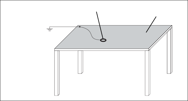
TB7100 Installation and Operation Manual Installation 43
© Tait Electronics Limited December 2005
4.2.2 Antenna Load
The base station has been designed to operate safely under a wide range of
antenna loading conditions. However, damage will occur if the load is
removed while the base station is transmitting. Transmitting into a low
VSWR will maximise the power delivered to the antenna.
4.2.3 Equipment Grounding
To ensure safe operation, the base station must be correctly grounded as
described in these installation instructions.
4.2.4 Installation and Servicing Personnel
The base station should be installed and serviced only by qualified
personnel.
4.3 Regulatory Information
4.3.1 Distress Frequencies
The 406 to 406.1MHz frequency range is reserved worldwide for use by
Distress Beacons. Do not program transmitters to operate in this frequency
range.
Figure 4.1 Typical antistatic bench set-up
common point ground
(building ground or
mains ground via
1MΩ series resistor)
conductive wrist strap dissipative rubber
bench mat

44 Installation TB7100 Installation and Operation Manual
© Tait Electronics Limited December 2005
4.3.2 FCC Compliance1
This device complies with part 15 of the FCC Rules. Operation is subject
to the condition that this device does not cause harmful interference.
4.3.3 Unauthorised Modifications
Any modifications you make to this equipment which are not authorised by
Tait Electronics Ltd. may invalidate your compliance authority’s approval to
operate the equipment.
4.3.4 Health, Safety and Electromagnetic Compatibility in Europe
In the European Community, radio and telecommunications equipment is
regulated by Directive 1999/5/EC, also known as the Radio and
Telecommunications Terminal Equipment (R&TTE) directive.
The requirements of this directive include protection of health and safety of
users, as well as electromagnetic compatibility.
Intended Purpose of
Product This product is an FM radio transceiver. Its intended purpose is for radio
communication in Private Mobile Radio (PMR) services or Public Access
Mobile Radio (PAMR) services.
Important This product can be programmed for frequencies or emis-
sions that may make its use illegal. A license must be
obtained before this product is used. All license require-
ments must be observed. Limitations may apply to transmit-
ter power, operating frequency, channel spacing, and emis-
sion.
Declaration of
Conformity Brief Declarations of Conformity appear on page 141. You can download
the formal Declaration of Conformity from http://eudocs.taitworld.com/.
You can also obtain a signed and dated paper copy of the Declaration of
Conformity from Tait Europe Ltd.
1. Refer to the specifications manual for more information on the compliance standards to which
the base station has been tested and approved.
TB7100 Installation and Operation Manual Installation 45
© Tait Electronics Limited December 2005
4.4 Environmental Conditions
4.4.1 Operating Temperature Range
The operating temperature range is –30°C to +60°C (–22°F to +140°F)
ambient temperature for the 25W base station and –30°C to +50°C (–22°F
to +122°F) ambient temperature for the 50W and 40W base stations.
Ambient temperature is defined as the temperature of the air at the intake to
the cooling fans.
4.4.2 Humidity
The humidity should not exceed 95% relative humidity through the
specified operating temperature range.
4.4.3 Dust and Dirt
For uncontrolled environments, the level of airborne particulates must not
exceed 100µg/m3.
4.5 Grounding and Lightning Protection
4.5.1 Electrical Ground
The base station modules are grounded by physical contact between the
module mounting points and the chassis. To ensure a good ground
connection you must tighten each module securely (for the correct torque
refer to “Replacing Modules” in the installation and operation manual).
A threaded grounding connector is provided on the rear of the tray for
connection to the site ground point (for more details refer to “Connections”
on page 65).
4.5.2 Lightning Ground
It is extremely important for the security of the site and its equipment that
you take adequate precautions against lightning strike. Because it is outside
the scope of this manual to provide comprehensive information on this
subject, we recommend that you conform to your country's standards
organisation or regulatory body.

46 Installation TB7100 Installation and Operation Manual
© Tait Electronics Limited December 2005
4.6 Recommended Tools
It is beyond the scope of this manual to list every tool that an installation
technician should carry. However, the following tools are specifically
required for installing the base station:
■Philips #2 tip screwdriver used to connect the DC power cables to the
DC power terminals
■Pozidriv PZ3 screwdriver for the M6 screws used to secure the tray to
the cabinet in Tait factory-assembled systems
■Torx T10 screwdriver for the M3 pan head screws with captured shake-
proof washer and flat washer used to secure the modules in the tray
■Torx T10 screwdriver for the M3 countersunk screws used to secure the
cover and the heatsink channels to the tray
■Pozidriv PZ1 screwdriver for the M3 pan head self-tapping screws used
to secure the fans.
You can also obtain the TBA0ST2 tool kit from your nearest Tait dealer or
Customer Service Organisation. It contains the basic tools needed to install,
tune and service the base station.
4.7 Ventilation
Always ensure there is adequate ventilation around the base station. Do not
operate at high duty cycles in a sealed cabinet. You must keep the ambient
temperature within the specified range, and we strongly recommend you
ensure that the cooling airflow is not restricted.
Important The cooling fans are mounted behind the front panel.
To ensure adequate airflow through the base station, do not
operate it for more than a few minutes with the fans discon-
nected (e.g. for servicing purposes).
4.7.1 Cabinet and Rack Ventilation
Refer to Figure 4.2 on page 47.
Adequate cooling airflow is critical to the performance of the base station.
The cooling airflow for the base station enters through the front panel and
exits at the rear of the tray. For optimum thermal performance, the heated
air that has passed through a base station must not be allowed to re-enter the
air intakes on the front panel.
Each base station requires an unobstructed airflow of 18m3/h (11cfm).
To allow enough cooling airflow through a cabinet mounted base station
we recommend the following:
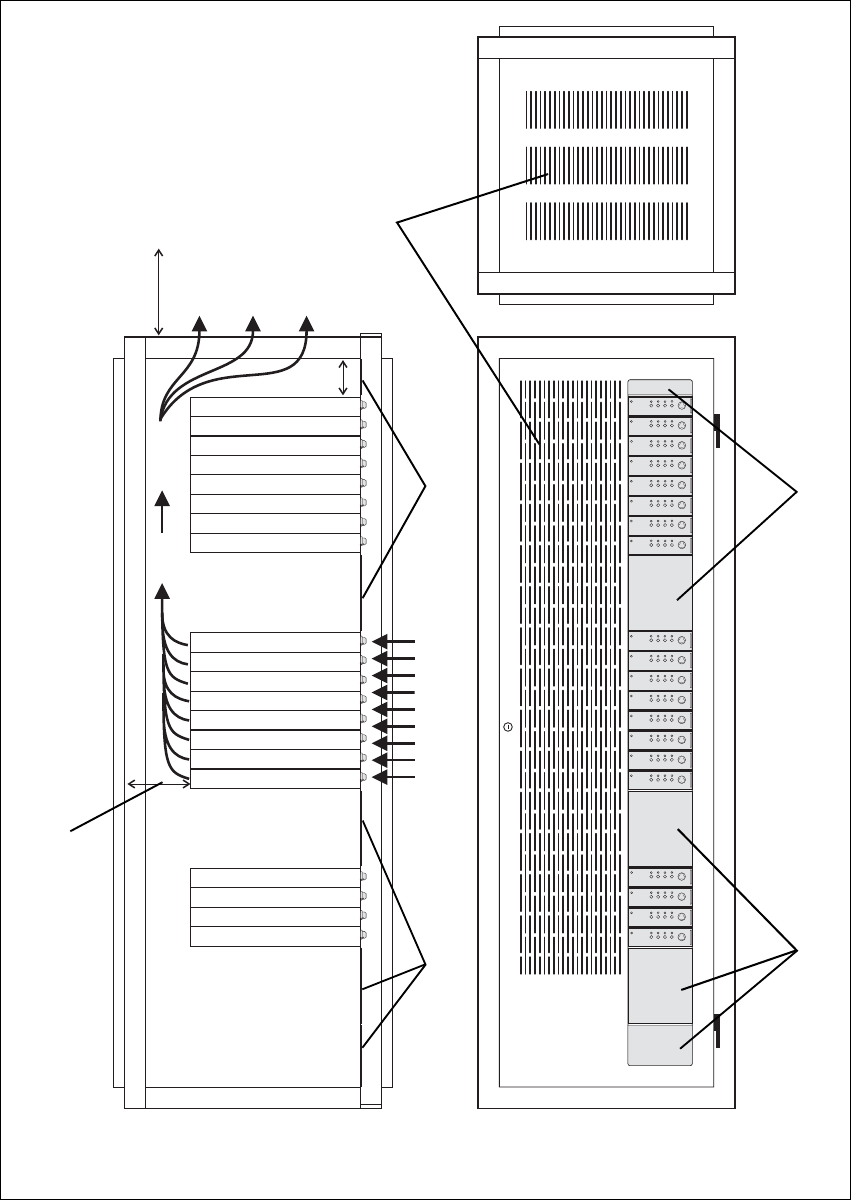
TB7100 Installation and Operation Manual Installation 47
© Tait Electronics Limited December 2005
Figure 4.2 Typical cabinet ventilation requirements
bventilation slots dairflow entry
cblanking panels eairflow exit
BUSY TF1 TF2 RF2
RF1 VOLUME
BUSY TF1 TF2 RF2
RF1 VOLUME
BUSY TF1 TF2 RF2
RF1 VOLUME
BUSY TF1 TF2 RF2
RF1 VOLUME
BUSY TF1 TF2 RF2
RF1 VOLUME
BUSY TF1 TF2 RF2
RF1 VOLUME
BUSY TF1 TF2 RF2
RF1 VOLUME
BUSY TF1 TF2 RF2
RF1 VOLUME
BUSY TF1 TF2 RF2
RF1 VOLUME
BUSY TF1 TF2 RF2
RF1 VOLUME
BUSY TF1 TF2 RF2
RF1 VOLUME
BUSY TF1 TF2 RF2
RF1 VOLUME
BUSY TF1 TF2 RF2
RF1 VOLUME
BUSY TF1 TF2 RF2
RF1 VOLUME
BUSY TF1 TF2 RF2
RF1 VOLUME
BUSY TF1 TF2 RF2
RF1 VOLUME
BUSY TF1 TF2 RF2
RF1 VOLUME
BUSY TF1 TF2 RF2
RF1 VOLUME
BUSY TF1 TF2 RF2
RF1 VOLUME
BUSY TF1 TF2 RF2
RF1 VOLUME
20cm
(8in)
2U
≥10cm
(≥4in)
side view front view
top view
c
c
d
e
b
c
c

48 Installation TB7100 Installation and Operation Manual
© Tait Electronics Limited December 2005
■a distance of 5cm minimum clearance to any obstruction to the front of
the tray.
■an open area of at least 50cm2 (8in2) per tray of ventilation slots or
louvres in front of the air intakes for the fans for each tray; for example
ten 6×85mm (0.25×3.3in) slots will allow the recommended airflow.
■a distance of 10cm minimum clearance to any obstruction to the rear of
the tray.
■an open area of at least 50cm2 (8in2) per tray of ventilation slots or
louvres in the top of the cabinet, or to the rear of each tray.
■a 2U gap at the top of the cabinet.
Note The ventilation opening must be unrestricted. If the slots or holes
are covered with a filter, mesh or grille, the open area must be
increased to allow the same airflow as an unrestricted opening.
The maximum ambient temperature entering the cabinet must not exceed
the maximum temperature specified for the base station.
If the base station is installed in a rack or cabinet with other equipment with
different ventilation requirements, we recommend that the base station be
positioned below this equipment.
Auxiliary Extractor
Fans If multiple base stations are fitted in a cabinet, auxiliary extractor fans may
be required to ensure adequate cooling. If fitted they should be capable of
extracting 18m3/h (11cfm) per base station in the cabinet.
If you have any other configuration, the performance of your system will
depend on how closely you comply with the base station airflow
requirements described above.
TB7100 Installation and Operation Manual Installation 49
© Tait Electronics Limited December 2005
4.8 Installing the Base Station
4.8.1 Unpacking the Equipment
Unpacking the
Base Station The base station is packed in a strong corrugated cardboard carton with top
and bottom foam cushions.
1. Cut the tape securing the flaps at the top of the carton and fold them
flat against the sides.
2. Rotate the carton carefully onto its side and then onto its top,
ensuring that none of the flaps is trapped underneath.
3. Slide the carton upwards over the foam cushions and lift it away.
Remove the cushion from the bottom of the base station.
4. Lift the base station clear of the remaining cushion.
Disposal of
Packaging If you do not need to keep the packaging, we recommend that you recycle
it according to your local recycling methods. The foam cushions are CFC-
and HCFC-free and may be burnt in a suitable waste-to-energy combustion
facility, or compacted in landfill.
4.8.2 Identifying the Mechanical Configuration
The base station is available in two different mechanical configurations—
with or without provision for an internal AC power supply unit.
The mechanical configuration with provision for an internal AC power
supply has the following distinguishing features:
■larger air intake on the right-hand side of the front panel
■provision for AC connector on the left-hand side of the rear panel (refer
to Figure 6.2 on page 66)
■ground point on the right-hand side of the rear panel rather than on the
left-hand side
■different SI board and internal cables.
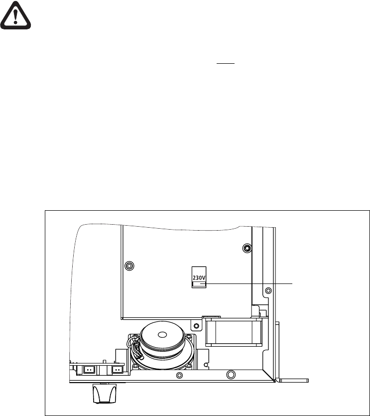
50 Installation TB7100 Installation and Operation Manual
© Tait Electronics Limited December 2005
4.8.3 Power Supply Options
The base station is available with or without an internal AC power supply
unit.
All base stations have an external DC input power connector which is used
as main power supply when no internal AC power supply unit is fitted.
When the internal AC power supply unit is fitted, the DC input can be used
as a DC backup power option. In case of AC mains failure the base station
will automatically and seamlessly switch to DC power input.
If no internal AC power supply unit is fitted, an external Tait T809-10-87xx
power supply can be used to supply the DC voltage required.
4.8.4 Setting the AC Mains Input Voltage
Warning!! The internal AC power supply unit contains
voltages that may be lethal. Refer to the ratings
label on the rear of the base station.
Ensure that all power sources (AC and DC) are disconnected
before opening the base station.
1. Disconnect all power sources before opening the base station.
2. Use a Torx T10 screwdriver to remove the 15 countersunk screws
securing the cover to the tray.
3. Set the 115V/230V AC mains voltage selector switch to the correct
AC mains input voltage (Figure 4.3).
Figure 4.3 115/230V AC mains voltage selector switch
115/230V AC mains
voltage selector switch
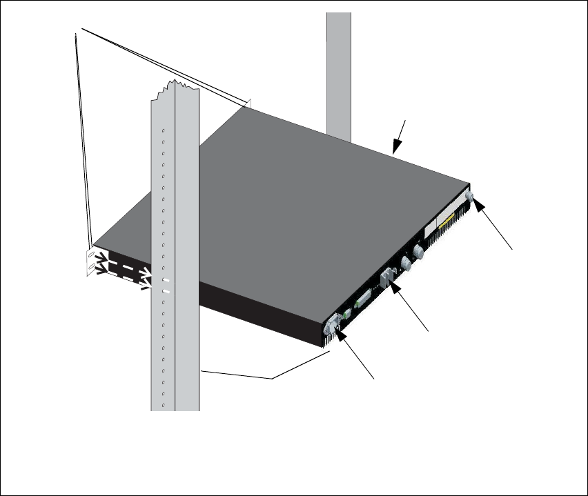
TB7100 Installation and Operation Manual Installation 51
© Tait Electronics Limited December 2005
4.8.5 Mounting the Base Station
1. Fit the base station into the cabinet or rack and secure it firmly with
an M6 (or 0.25in if you are using imperial fittings) screw, flat and
spring washer in each of the four main mounting holes b, as shown
in Figure 4.4 on page 51.
2. The base station can be wall-mounted by rotating the front mounting
brackets and fitting the optional rear brackets (TBBA03-01). When
the base station is wall-mounted ensure the airflow is from bottom to
top (front panel mounted down) or side to side.
3. For transport or in installations subject to vibration, the base station
should be supported at the rear using a transit bracket
(Tait recommends to use the TB7100 transit bracket, Tait part
number 302-05282-00).
Figure 4.4 Base station mounting points (configuration with AC power supply unit shown)
bmain mounting holes eDC power connector
cbase station fAC power connector
dground point Grack frame
G
E
c
b
f
D
52 Installation TB7100 Installation and Operation Manual
© Tait Electronics Limited December 2005
4.8.6 Cabling
We recommend that you route all cables to and from the base station along
the side of the cabinet so the cooling airflow is not restricted.
Cables should be well supported so that the connectors or terminals on the
base station and on the ends of the cables do not have to support the full
weight of the cables.
Cables must be routed so that they do not restrict the air outlets at the rear
of the base station.
4.8.7 Accessories
The base station can use the following accessories:
■T809-10-87xx power supply
■TBBA03-01 wall mounting kit
■
TBBA03-02 duplexer kit
(mechanical configuration without internal AC power supply unit)
■TBBA03-03 duplexer kit
(mechanical configuration with internal AC power supply unit)
■TMAA02-01 fist microphone.

TB7100 Installation and Operation Manual Replacing Modules 53
© Tait Electronics Limited December 2005
5 Replacing Modules
This section describes how to:
■remove and open and close the base station
■remove and fit the modules and components
General Important Before disassembling the base station, disconnect the base
station from any test equipment or power supply.
Disassemble only as much as necessary to replace the defective parts.
Inspect all disassembled parts for damage and replace them, if necessary.
Observe the torque settings indicated in the relevant figures.
Important To ensure adequate airflow through the base station, do not
cover the fan intake grill on the front panel. Do not operate
for more than a few minutes with the fan intake covered.
Important The transmitter and receiver modules must only be replaced
with base station modules.
Saving the Base
Station
Configuration
Before replacing a module in the base station, you should decide whether
you need to save its configuration data. If you are unsure whether you have
a record of the configuration, use the Programming Application to read the
base station and save the configuration files before removing any modules.
Once you have replaced the module, you will be able to restore the original
configuration by programming the saved configuration back into the base
station. If one or more of the modules is faulty, you may be unable to read
the base station. In this case, you will have to restore the configuration from
a back-up file. Refer to the section “Preparation for Operation” on page 77
for more information.
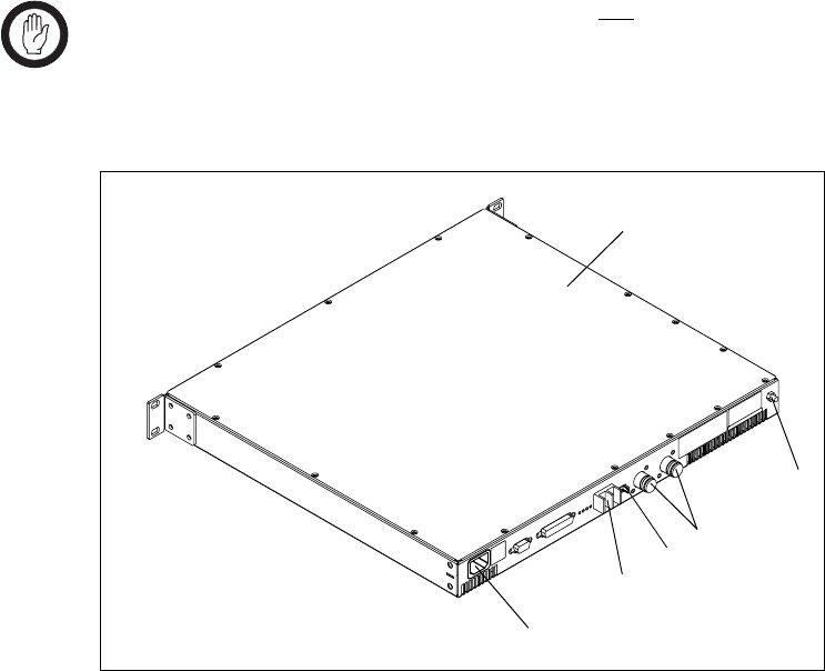
54 Replacing Modules TB7100 Installation and Operation Manual
© Tait Electronics Limited December 2005
5.1 Removing the Base Station and Opening the Tray
Important The modules in the base station are not hot-pluggable. It is
recommended the tray is removed from the rack before any
modules are replaced.
1. If an internal AC Power supply is fitted, disconnect the base station
from AC power g.
2. Remove the fuse e at the rear of the base station to disconnect the
base station from DC power.
3. Use a Philips #2 screwdriver to disconnect the cables from the DC
power connector f.
4. Disconnect the antenna connectors for transmit and receive d.
5. Disconnect any other connectors.
6. Disconnect the ground cable from the ground point c.
7. Use a PZ2 Pozidriv screwdriver to remove the four M6 screws, and
remove the base station from the rack.
8. Use a Torx T10 screwdriver to remove the 15 countersunk screws.
Remove the tray cover b.
Figure 5.1 Opening the tray
b
e
f
d
c
Configuration with internal AC power supply unit shown g
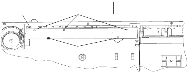
TB7100 Installation and Operation Manual Replacing Modules 55
© Tait Electronics Limited December 2005
5.2 Replacing the UI Board
Removal 1. Remove the volume knob by pulling slowly but firmly. The knob is
a friction fit and can leave the collet behind on the shaft. If this
happens, remove the collet from the shaft and place inside the knob.
2. Disconnect the speaker connector b.
3. Use a Torx T10 screwdriver to remove the three screws c together
with the spring washers and flat washers.
4. Insert the card remover tool (220-02034-xx) from the tool kit
(TBA0ST2), or a small flat-bladed screwdriver into the two small
holes at the bottom of the UI board. Lever the board completely off
the spring clips d.
5. Carefully slide the UI board towards the rear of the base station until
the volume-control shaft clears the front panel. Lift the UI board clear
of the chassis.
6. Disconnect the two Micro-MaTch connectors e.
Fitting 1. Plug the two Micro-MaTch connectors e into the UI board.
The Micro-MaTch connector for the transmitter is closest to the
edge of the UI board.
2. Align the volume-control shaft with the hole in the front panel, also
align the programming/microphone connector and function buttons
as the board is slid into place.
3. Gently slide the UI board into position so that the spring clips d are
engaged. Press firmly around the spring clips to ensure they are
engaged fully.
4. Use a Torx T10 screwdriver to fasten the three screws c to 4.5lb·in
(0.5N·m).
5. Plug the speaker connector b into the UI board.
6. Fit the volume knob onto the shaft and press firmly until fully seated.
Figure 5.2 Removing the UI board
e
d
c
b
Cables not shown.
Torx T10
4.5lb·in (0.5N·m)
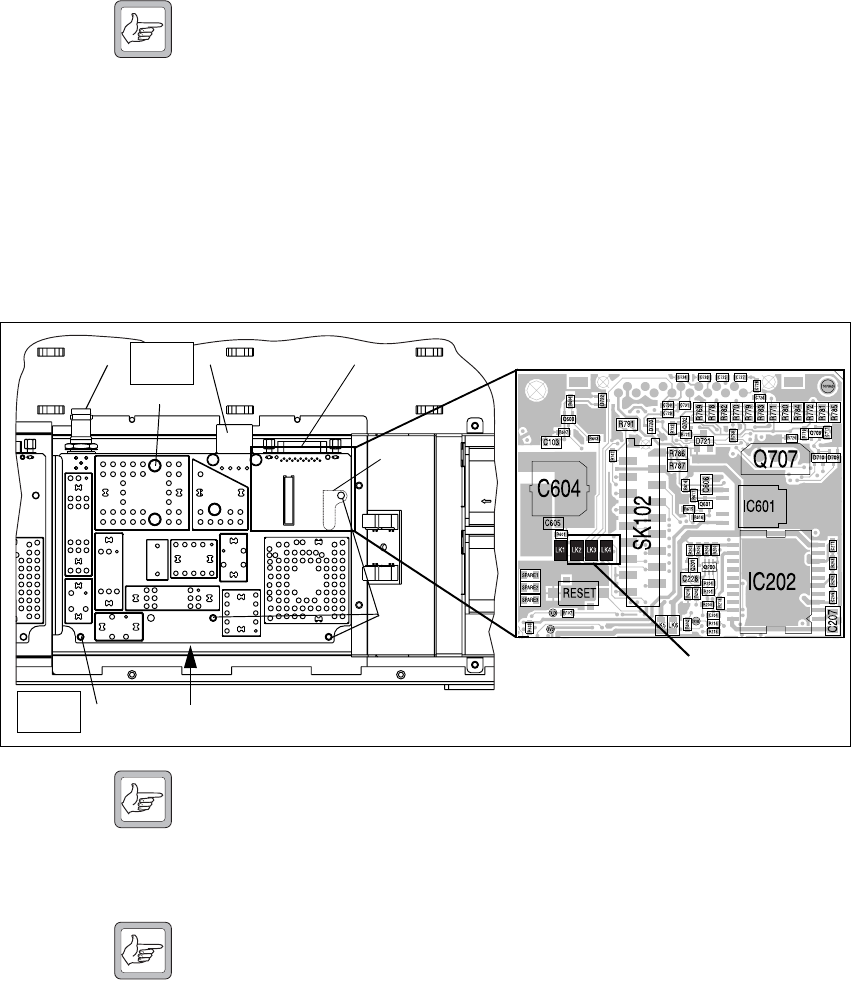
56 Replacing Modules TB7100 Installation and Operation Manual
© Tait Electronics Limited December 2005
5.3 Replacing the Receiver Module
Removal Note Release the latch underneath the DC power connector before
attempting to disconnect it.
1. Disconnect the cables to the RF b, DC power c, system interface
d, and the user interface e connectors.
2. Use a Torx T10 screwdriver to remove the five screws f and g
together with the spring washers and flat washers.
3. Lift the receiver module clear of the chassis.
4. Make sure not to lose the metal heatsink g for the audio PA.
Note Although the boards of the transmitter and receiver modules look
alike, the board on the transmitter module can not replace a
receiver module. There is no heat transfer plate on the receiver
module. Check that the replacement module has links LK2, LK3
and LK4 not fitted as shown in Figure 5.3.
Fitting Note Before fitting the receiver module, make sure that the metal heat-
sink h for the audio PA is fitted to the tray chassis.
1. Place one screw g into the hole above the metal heatsink plate by:
a. holding the module at a 60° angle
b. fitting the screw on the Torx driver
c. slipping it through the shield hole and into the board hole.
2. Position the receiver module inside the tray chassis.
3. Use a Torx T10 torque-driver to tighten the screws f and g to
4.5lbf·in (0.5N·m).
4. Connect the cables to the RF b, DC power c, system interface d,
and user interface e connectors.
Figure 5.3 Replacing the receiver module
f
g
e
bcd
f
Check that links LK2, LK3 and
LK4 are not fitted.
Torx T10
4.5lb·in
Torx T10
4.5lb·in
h
Cables not shown.
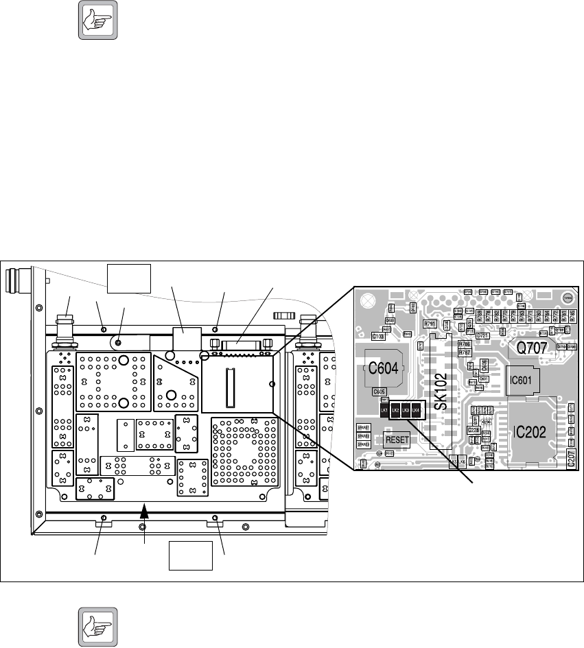
TB7100 Installation and Operation Manual Replacing Modules 57
© Tait Electronics Limited December 2005
5.4 Replacing the Transmitter Module
Removal Note Release the latch underneath the DC power connector before
attempting to disconnect it.
1. Disconnect the cables to the RF b, DC power c, system interface
d, and the user interface f connectors.
2. Use a Torx T10 screwdriver to remove the screw h fastening the
temperature sensor to the heatsink.
3. Use a Torx T10 screwdriver to remove the four screws g fastening
the heatsink to the tray chassis.
4. Lift the transmitter module clear of the tray chassis.
Fitting Note Although the boards of the transmitter and receiver modules look
alike, the board on the transmitter module can not replace a
receiver module. There is no heat transfer plate on the receiver
module. Check that the replacement module has links LK2, LK3
and LK4 not fitted as shown in Figure 5.4.
1. Position the transmitter module inside the tray chassis.
2. Use a Torx T10 torque-driver to fasten the four screws g to 4.5lbf·in
(0.5N·m).
3. Use a Torx T10 torque-driver to fasten the temperature sensor with
the screw h to 4.5lbf·in (0.5N·m).
4. Connect the cables to the RF b, DC power c, system interface d,
and the user interface f connectors.
Figure 5.4 Replacing the transmitter module
g
f
bcd
g
e
Check that links LK2, LK3 and
LK4 are not fitted.
g
g
gh
Torx T10
4.5lb·in
Torx T10
4.5lb·in Cables not shown.
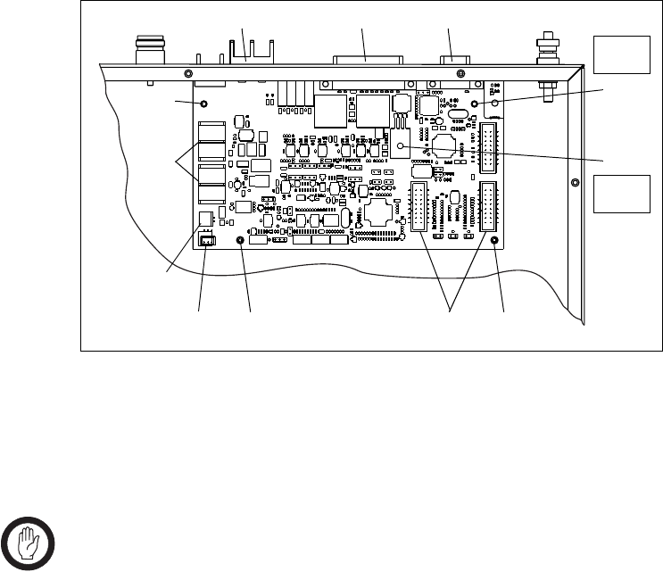
58 Replacing Modules TB7100 Installation and Operation Manual
© Tait Electronics Limited December 2005
5.5 Replacing the SI Board
Removal 1. Disconnect the system interface cables e to the transmitter and the
receiver, the fan control cable f, the temperature sensor cable g, and
the mains power present cable, and move them to one side.
2. Remove the DC power cables h and move them to one side.
Note the connection positions.
3. Use a Torx T10 screwdriver to remove the two screws j.
Use a PZ1 Pozidriv screwdriver to remove the screw i on the
heatsink of U406.
4. Carefully lift the front of the SI board off the spring clips 1).
5. Carefully slide the SI board towards the front of the base station until
the connectors b, c and d clear the rear panel. Lift the SI board
clear of the chassis.
Fitting 1. Slide the SI board into the tray chassis by fitting the connectors b, c
and d into the rear panel.
2. Press down firmly on the front of the SI board to engage the two
spring clips j.
Important Make sure that the thermal pad is fitted under and the
plastic insulating washer is fitted on U406.
3. Use a torque-driver to fasten the two screws j (Torx T10) the screw
i (PZ1) on the heatsink of U406 to 4.5lb·in (0.5N·m).
4. Connect the system interface cables e to the transmitter and the
receiver, the fan control cable f, the temperature sensor cable g, and
the DC power cables h.
Figure 5.5 Replacing the SI board
g
h
bc d
Torx T10
4.5lb·in
jj
i
1)
1) ef
PZ1
4.5lb·in
Cables not shown.
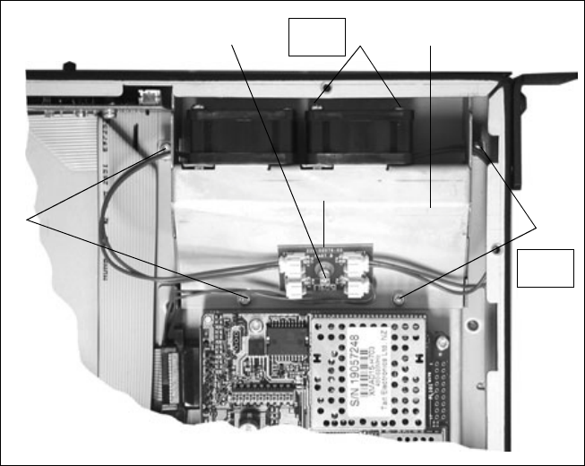
TB7100 Installation and Operation Manual Replacing Modules 59
© Tait Electronics Limited December 2005
5.6 Replacing the Transmitter and Receiver Fans
Removal 1. Use a Torx T10 screw driver to remove the four screws b securing
the fan duct d in the tray chassis.
2. Disconnect the fan control loom from the fan power board c.
Slide back the fan duct d and lift clear.
3. Unplug the fan to be replaced from the fan power board c on the
fan duct d.
4. Use a PZ1 Pozidriv screwdriver to remove the two M3×25mm
screws e and remove the fan.
Fitting 1. Place the fan into position on the fan duct e and use a PZ1
screwdriver to fasten the two M3×25 screws e to 4.5lb·in (0.5N·m).
2. Thread the fan cable through the hole in the side of the fan duct.
Plug the fan into the fan power board c.
3. Slide the fan duct d into the chassis. Plug the fan control loom into
the fan power board c.
4. Use a Torx T10 screwdriver to fasten the four screws b to 4.5lb·in
(0.5N·m).
Figure 5.6 Replacing the transmitter and receiver fans
b
b
c
def
Torx T10
4.5lb·in
PZ1
4.5lb·in

60 Replacing Modules TB7100 Installation and Operation Manual
© Tait Electronics Limited December 2005
5.7 Replacing the Fan Power Board
Note The fan power board is manufactured as part of the UI board and
cannot be ordered separately. For more information, refer to
“Spare Parts” in the service manual.
The circled numbers in this section refer to the items in Figure 5.6 on
page 59.
1. Disconnect the fan control cable and the fan cables from the fan
power board c.
2. Use a Torx T10 screwdriver to remove the screw f attaching the fan
power board c to the fan duct d.
3. Fitting is carried out in reverse order.
5.8 Replacing the Temperature Sensor Board
Note The temperature sensor board is manufactured as part of the
SI board and cannot be ordered separately. For more information,
refer to “Spare Parts” in the service manual.
1. Disconnect the temperature sensor cable from the SI board
(Figure 5.5, g).
2. Use a Torx T10 screwdriver to remove the screw (Figure 5.4, h)
attaching the temperature sensor board to the transmitter module.
3. Fitting is carried out in reverse order.
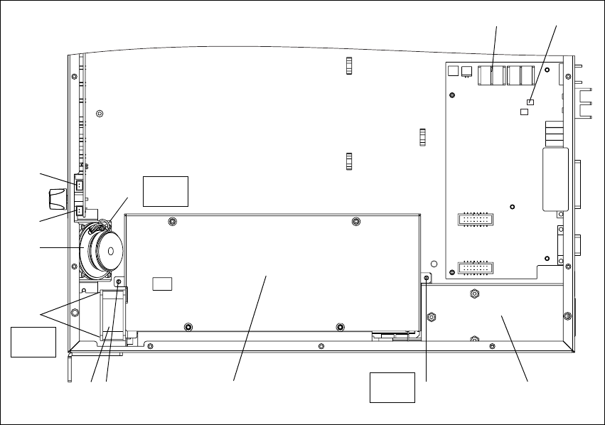
TB7100 Installation and Operation Manual Replacing Modules 61
© Tait Electronics Limited December 2005
5.9 Replacing the AC Power Supply Unit, Fan and Filter
Module
Removal 1. Disconnect the base station from AC mains power.
2. Remove the fuse at the rear of the base station to disconnect the base
station from DC power.
3. Disconnect the fan g at connector PL7 1! of the UI board.
4. Use a Torx T10 screwdriver to remove the two screws e that hold
the AC power supply f unit to the main chassis.
5. Slide the AC power supply unit from its position to gain access to the
fan.
6. Use a PZ1 Posidriv screwdriver to remove the two M3 x 25mm
screws h that hold the fan in place, and remove the fan.
7. Disconnect the cable for the mains fail signal at J110 c and the
DC power cable at J102 b of the SI board.
8. Disconnect the connection (not shown) from the AC filter module
d to the AC power supply unit, and remove the AC power supply
unit.
9. Slide the AC filter module from its position and remove it.
Figure 5.7 Replacing the AC power supply unit, fan, filter module, and speaker
h
e
Torx T10
4.5lb·in dfe
1)
bc
g
PZ1
4.5lb·in
i
1!
jTorx T10
4.5lb·in
Cables not shown.
62 Replacing Modules TB7100 Installation and Operation Manual
© Tait Electronics Limited December 2005
Fitting 1. Slide the AC filter module d into the securing tabs at the rear of the
tray.
2. Place the fan g into position on the AC power supply unit f and
use a PZ1 screwdriver to fasten the two M3×25 screws h to 4.5lb·in
(0.5N·m).
3. Connect the AC power supply unit to the AC filter module.
4. Slide the AC power supply unit into position on the tray and connect
the fan to connector PL7 1! on the UI board.
5. Use a Torx T10 screwdriver to fasten the two screws e that hold the
AC power supply unit in place to 4.5lb·in (0.5N·m).
6. Connect the cable for the mains fail signal at J110 c and the DC
power cable at J102 b of the SI board.
5.10 Replacing the Speaker
The circled numbers in this section refer to the items in Figure 5.7 on
page 61.
1. Disconnect the speaker cable from connector PL2 1) on the
UI board.
2. Use a Torx T10 screw driver to remove the two screws and washers
i securing the speaker i to the tray.
3. Fitting is carried out in reverse order. The torque for the Torx T10
screws i is 4.5lb·in (0.5N·m).
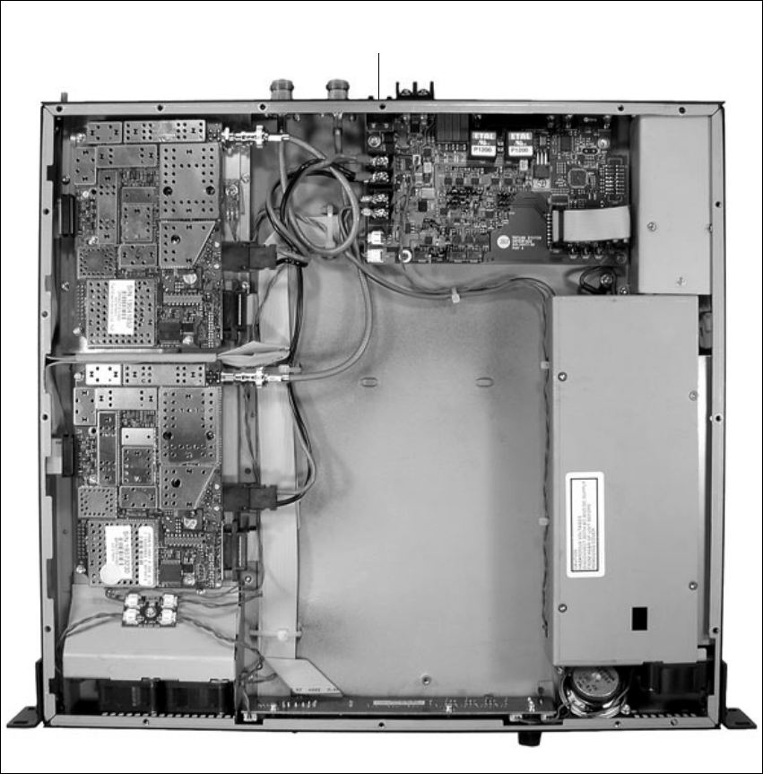
TB7100 Installation and Operation Manual Replacing Modules 63
© Tait Electronics Limited December 2005
5.11 Final Reassembly
Figure 5.8 shows the assembled configuration with internal AC power
supply unit. Figure 5.9 shows the assembled configuration without internal
AC power supply unit.
1. Ensure all internal cables are connected correctly as shown below.
2. Place the tray cover onto the chassis.
3. Use a Torx T10 torque-driver to fasten the tray cover with the 15
countersunk screws to 4.5lb·in (0.5N·m).
4. Fit the fuse b at the rear of the base station.
Figure 5.8 Final reassembly (configuration with internal AC power supply unit)
Fuse
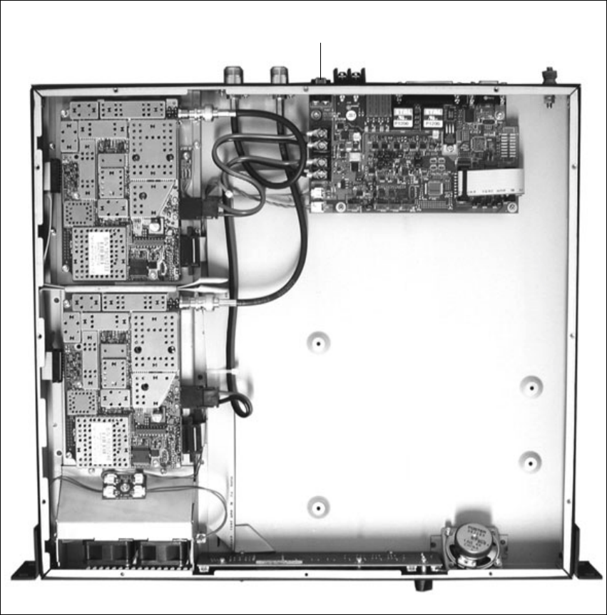
64 Replacing Modules TB7100 Installation and Operation Manual
© Tait Electronics Limited December 2005
Figure 5.9 Final reassembly (configuration without internal AC power supply unit)
Fuse
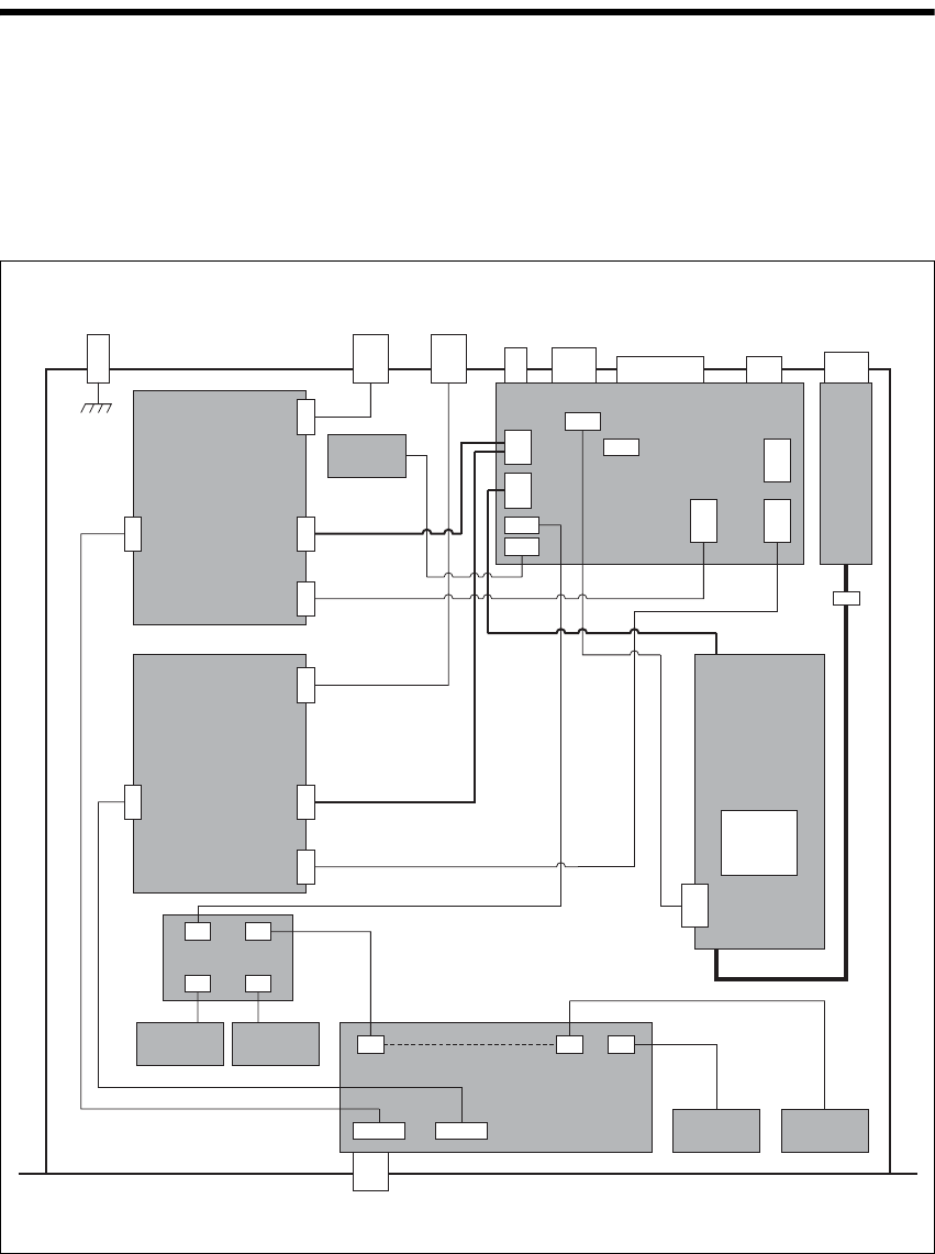
TB7100 Installation and Operation Manual Connections 65
© Tait Electronics Limited December 2005
6 Connections
Overview This section gives an overview of looms and cables, and describes the
specifications and pinouts of the external and internal connectors.
Figure 6.1 provides an overview of the connections.
For information on the factory connector and the internal options
connector of the transmitter and receiver, refer to the PCB information.
Figure 6.1 Connectors, looms and cables
DC Input
Connector System
Connector Serial Data
Connector AC Input
Connector
Rx
Connector
Tx/Ant
Connector
Ground
Point
Transmitter
Module
UI Board
AC
Power Supply
Unit
Fan
FanFan
Fan Power Board
Speaker
Temperature
Sensor
Prog/Mic
Connector
Receiver/SI
DC power
RF
Transmitter/SI
RF
Receiver/UI
Transmitter/UI
AC Input Filter
Module
115V/230V
Selector
Switch
SI Board
Fuse
Mains fail signal
SK100
PL100 SK101 SK103
SK100
PL100 SK101 SK103
RF connector
DC power
connector
Auxiliary
connector
User interface
connector
Receiver
Module
RF connector
DC power
connector
Auxiliary
connector
User interface
connector
J102 J103
J105 J106 J104
J201
J200
J110
J100 J202
J101
DC power
Fan power
SK1
SK3
SK2
PL2PL7PL8
PL4
PL3
PL5
PL6
Factory
only
PL101
J600
DC Output
AC power
Configuration with internal AC power supply unit shown
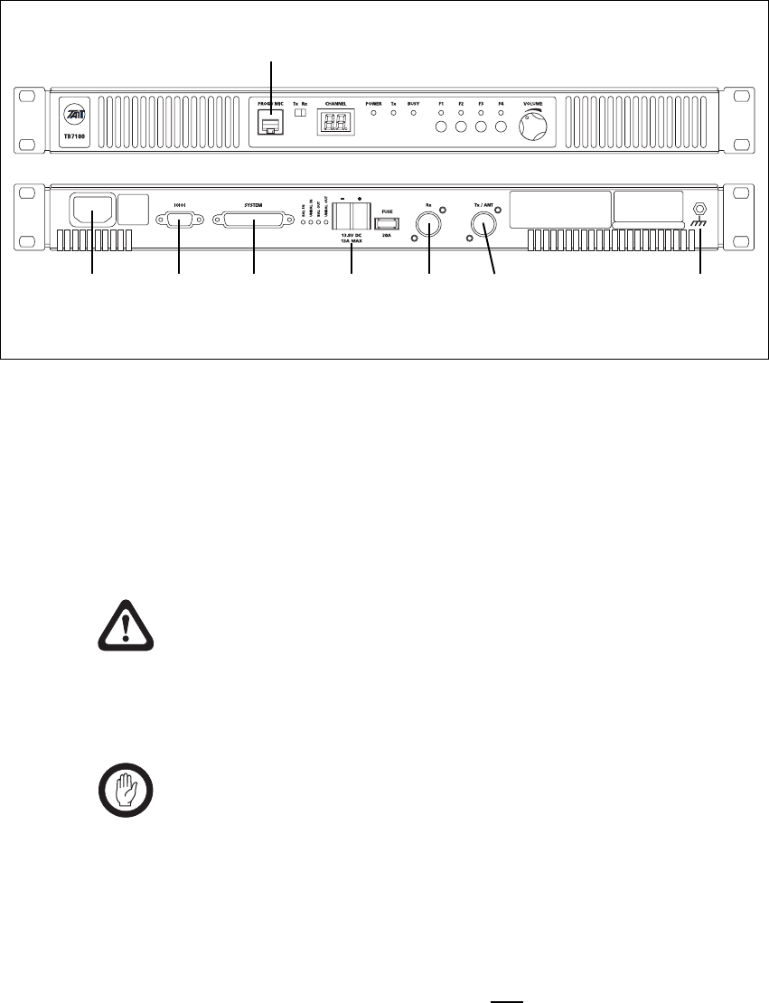
66 Connections TB7100 Installation and Operation Manual
© Tait Electronics Limited December 2005
6.1 External Connectors
Figure 6.2 shows the external connectors:
AC Power
Connection If an internal AC power supply unit is fitted, AC power is available in
195VAC to 264VAC or 99VAC to 135VAC. The voltage selector switch is
located under the base station cover. (Refer to “Setting the AC Mains Input
Voltage” on page 50.)
The AC power connector at the rear of the base station is a standard 3-way
AC pin connector.
Warning!! The internal AC power supply unit contains
voltages that may be lethal. Refer to the ratings
label on the rear of the base station. The internal
AC power supply contains no user-servicable
parts.
Important Wrong mains voltage! Before connecting to the AC power
connector, ensure that the internal 115V/230V voltage
mains selector switch is set to the correct mains voltage.
The base station must be installed so that the rear of the base station is
located in a service access area. The internal AC power supply unit must be
connected to the mains supply source by trained personnel in accordance
with local and national regulations.
Ensure that all power sources (AC and DC) are disconnected
before opening the base station.
Figure 6.2 External connectors (configuration with internal AC Power supply unit shown)
programming/microphone
connector (PROG/MIC)
ground
point
serial data
connector
(IOIOI)
system
connector
(SYSTEM)
DC power
connector
(13.8VDC
13A MAX)
receiver
antenna
connector
(RX)
transmitter
antenna
connector
(TX/ANT)* *Tx/ANT is Tx and Rx, if the duplexer is fitted.
AC power
connector
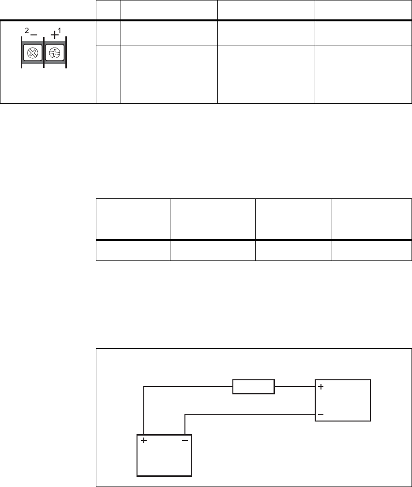
TB7100 Installation and Operation Manual Connections 67
© Tait Electronics Limited December 2005
DC Power
Connection The base station is designed to accept a nominal 13.8V DC, with negative
ground.
The DC power connector (J105) at the rear of the base station is a heavy-
duty M4 screw terminal connector suitable for many forms of connection.
You must connect the DC supply from the battery to the base station via a
readily accessible disconnect device such as a fuse or DC-rated circuit
breaker with the appropriate rating, as shown in the table below. The DC
input leads should be of a suitable gauge to ensure less than 0.2V drop at
maximum load over the required length of lead.
Terminate the DC input leads with a suitable crimp connector for attaching
to the J105 M4 screws.
Ground Point The ground point is a terminal for grounding the tray to the mounting rack.
Pin Signal Name Signal Type Notes
1 13.8VDC input
2 ground input
external view
Nominal Supply
Voltage Input Voltage
Range
Circuit
Breaker/Fuse
Rating
Recommended
Wire Gaugea
a. For a length of 1.5m to 2m (5ft to 6.5ft) (typical).
13.8VDC 10VDC to 16VDC 20A 8AWG / 8.35mm2
Figure 6.3 Recommended DC power connection
Battery
TB7100
base station
Circuit Breaker
or Fuse

68 Connections TB7100 Installation and Operation Manual
© Tait Electronics Limited December 2005
RF Connections
(RXand TX/ANT)The RF input to the base station is via the RX connector (N-type) on the
rear panel of the base station. The RF output is via the TX/ANT connector
(N-type) on the rear panel of the base station.
The RF connector is an N-type connector with an impedance of 50Ω.
Important The maximum RF input level is +27dBm. Higher levels
may damage the radio.
Pin Signal Name Signal Type Notes
1 RF RF analog
2 GND RF ground
BC
rear view

TB7100 Installation and Operation Manual Connections 69
© Tait Electronics Limited December 2005
System Connector
(SYSTEM)The system connector (J106) at the rear of the base station is a 25-way
standard-density D-range socket.
Pin Signal Name Signal Type Notes
1 Rx line output + audio output transformer isolated line <6dBm
2 Tx/Rx digital input 1
(AUX_GPI1) input high ≥1.7 V, low ≤0.7 V
3 Tx/Rx digital input 2
(AUX_GPI2)
4 Rx line output – audio output transformer isolated line
5 Tx line input + audio input transformer isolated line
6 Tx/Rx digital input 3
(AUX_GPI3) input high ≥1.7 V, low ≤0.7 V
7 Tx/Rx digital input 4
(AUX_GPIO4) input output: high ≥3.1 V (no load),
low <0.6 V (10mA sink)
input: high ≥1.7 V, low ≤0.7 V
8 Tx line input – audio input transformer isolated line
9 RSSI output DC signal, 0.6 to 2.5V
10 Tx digital in/out 1
(TX_AUX_GPIO5) input/output output: high ≥3.1 V (no load),
low <0.6 V (10mA sink)
input: high ≥1.7 V, low ≤0.7 V
11 Tx audio input audio input
12 Tx digital in/out 2
(TX_AUX_GPIO6) input/output output: high ≥3.1 V (no load),
low <0.6 V (10mA sink)
input: high ≥1.7 V, low ≤0.7 V
13 ground ground
14 Rx gate output open collector
15 Tx key input active low
16 Rx relay (comm) output opto-isolated
17 Rx relay (NO or NC) output
18 Rx Inhibit input 0 to 3.3V, active low
19 Rx digital in/out 1
(RX_AUX_GPIO5) input/output output: high ≥3.1 V (no load),
low <0.6 V (10mA sink)
input: high ≥1.7 V, low ≤0.7 V
20 Tx Opto input + input input voltage range 10VDC to
60VDC
21 Tx Opto input – input
22 Rx digital in/out 2
(RX_AUX_GPIO6) input/output output: high ≥3.1 V (no load),
low <0.6 V (10mA sink)
input: high ≥1.7 V, low ≤0.7 V
23 Digital output/Tx relay output active low, sinks up to 250mA
24 Rx audio output output <4.4Vpp
25 13.8 volt output power output resetable SMD fuse 1.5A
external view
B
C
D
E
F
G
H
I
J
1)
1!
1@
1#
1$
1%
1^
1&
1*
1(
2)
2!
2@
2#
2$
2%
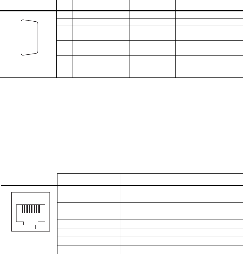
70 Connections TB7100 Installation and Operation Manual
© Tait Electronics Limited December 2005
Serial Data
Connector (IOIOI)The serial data connector (J1054) labelled IOIOI is a 9-way female D-range
connector, which provides a data connection to the base station.
Programming/Micro
phone Connector
(PROG/MIC)
The PC running the programming and calibration application is connected
to the base station via the programming/microphone connector (SK3) of
the UI board. The programming/microphone connector is an 8-way RJ45
socket.
Use the TPA-SV-006 or the T2000-A19 programming lead and a
TMAA20-04 adapter to connect the PC to the base station. It is possible to
plug the RJ11 directly into the RJ45 socket without the use of the adapter,
but this is not recommended. A microphone can also be connected to the
base station via this connector.
Pin Signal Name Signal Type Notes
1 not connected not used
2 receive data output data transmitted by TB7100
3 transmit data input data received by TB7100
4 not connected not used
5 ground ground
6 not connected not used
7 ready to transmit output request to send
8 clear to send input clear to send
9 not connected not used
h
j
bg
i
c
d
e
f
external view
Pin Signal Name Signal Type Notes
1 not connected not connected
2 +13V8_SW output +13.8V, 250mA
3 TXD input transmit data
4 PTT input PTT
5 MIC_AUD_IN input voice band (microphone) input
6 GND ground
7 RXD output receive data
8 not connected not connected
12345678
external view

TB7100 Installation and Operation Manual Connections 71
© Tait Electronics Limited December 2005
6.2 Internal Connectors
6.2.1 Transmitter and Receiver Connectors
The internal connectors of the transmitter and receiver are the same for both
modules.
Note The signals on the user interface connectors are different for the
transmitter and the receiver.
RF Connectors The RF connectors of the transmitter and the receiver are N-type
connectors with an impedance of 50Ω.
DC Power
Connectors The DC power connectors of the transmitter and the receiver are the
interface for the primary 13.8V power source. There are different
DC power connectors for the 50W/40W and 25W versions.
Pin Signal name Signal type Notes
1AGND ground
2 SPK– analog output not connected
3 SPK+ analog output not connected
4 13.8VDC DC power input
external view
50W/40W
1 2 3 4
external view
25W
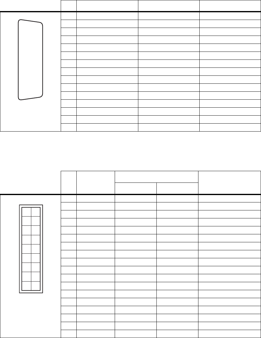
72 Connections TB7100 Installation and Operation Manual
© Tait Electronics Limited December 2005
Auxiliary
Connectors The auxiliary connectors of the transmitter and receiver are 15-way
standard-density D-range sockets.
User Interface
Connector The user interface connectors (SK100) of the transmitter and the receiver is
a 15-way moulded plastic connector.
Pin Signal Name Signal Type Notes
1 AUX GPIO7
2 AUX GPIO4
3 AUX RXD input
4 AUX GPI3
5 AUX GPI2
6 RSSI output
7 AUX TAP IN input
8 13.8VDC SW output
9 AUX GPIO6
10 AUX GPIO4
11 AUX TXD output
12 AUX GPI1
13 AUD TAP OUT output
14 AUX MIC AUD input
15 AGND ground
external view
J
B
C
D
E
F
G
H
I
1)
1!
1@
1#
1$
1%
Pin Signal Name Signal Type Notes
Transmitter Receiver
1 RX AUD no connection no connection no connection
2 13.8VDC no connection output +13V8DC for UI board
3 CH TXD input input programming data
4 CH PTT input no connection microphone PTT
5 CH MIC AUD input output audio from microphone
6 AGND ground ground analog ground
7 CH RXD output output programming data
8 DGND ground ground digital ground
9 CH ON OFF output output digital ground
10 VOL WIP DC input input volume control
11 CH SPI D0 output output
12 CH LE output output
13 CH GPIO1 output output digital ground
14 3.3VDC no connection output +3V3DC for UI board
15 CH SPI D1 input input
16 CH SPI CLK output output
17 SPK- no connection output speaker audio
18 SPK+ no connection output speaker audio
12
34
56
78
10
12
14
16
18
9
11
13
15
17
external view
pin 1 closest to PCB
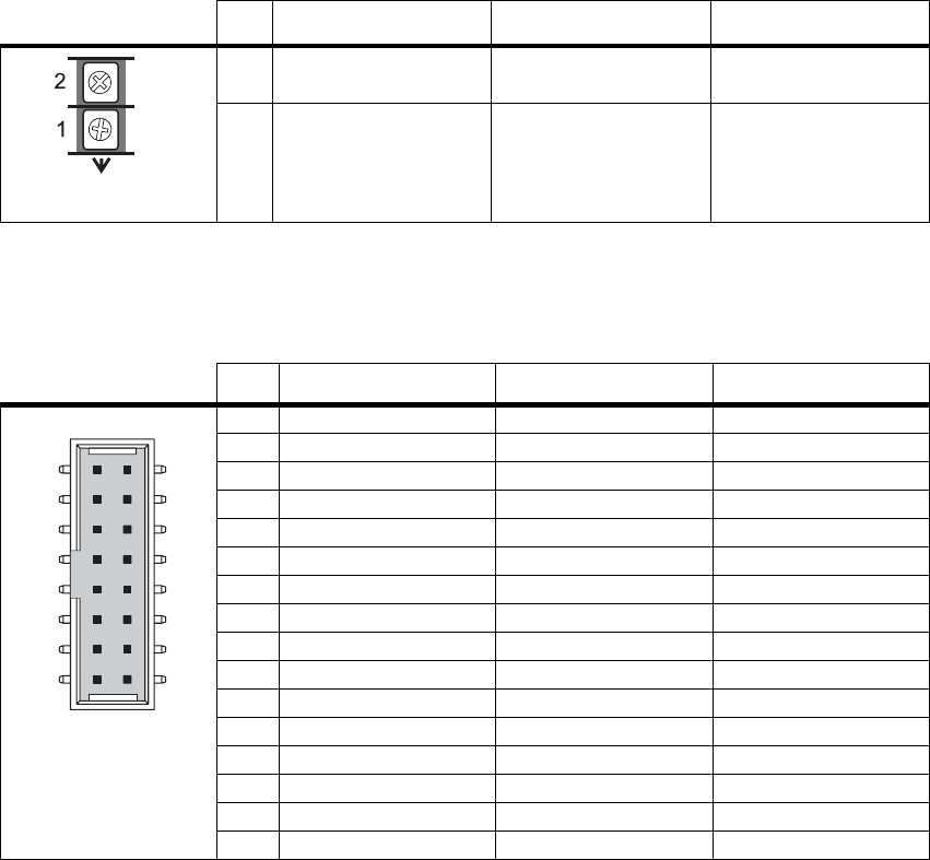
TB7100 Installation and Operation Manual Connections 73
© Tait Electronics Limited December 2005
6.2.2 SI Board Connectors
DC Power
Connectors The two DC power connectors (J102 and J103) on the SI board are heavy-
duty M4 screw terminals. J102 (if fitted) accepts power from the internal AC
power supply unit. J103 distributes the DC power to the transmitter and the
receiver.
System Interface
Connector to
Transmitter
The system interface connector (J101) to the transmitter is a 16-way surface-
mounted connector.
Pin Signal Name Signal Type Notes
1 Tx and Rx 13.8VDC J102 :input
J103: output
2 Tx and Rx ground J102 :input
J103: output
external view
Pin Signal Name Signal Type Notes
1 TX_AUX_GPIO7 output Tx key signal
2 TX_AUX_GPIO6 bidirectional digital input/output
3 TX_AUX_GPIO5 bidirectional digital input/output
4 TX_AUX_GPIO4 bidirectional digital input/output
5 TX_AUX_RXD input data
6 TX_AUX_TXD output data
7 TX_AUX_GPI3 input digital input
8 TX_AUX_GPI1 input digital input
9 TX_AUX_GPI2 input digital input
10 TX_AUD_TAP_OUT no connection
11 TX_RSSI no connection
12 TX_MIC_AUD output
13 TX_AUD_TAP_IN output Tx audio
14 TX_GND ground ground
15 TX_13V8 no connection
16 N/C no connection
external view
12
1615
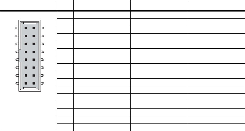
74 Connections TB7100 Installation and Operation Manual
© Tait Electronics Limited December 2005
System Interface
Connector to
Receiver
The system interface connector (J100) to the receiver is a 16-way surface-
mounted connector.
Pin Signal Name Signal Type Notes
1 RX_AUX_GPIO7 input gate signal
2 RX_AUX_GPIO6 bidirectional digital input/output
3 RX_AUX_GPIO5 bidirectional digital input/output
4 RX_AUX_GPIO4 bidirectional digital input/output
5 RX_AUX_RXD input data
6 RX_AUX_TXD output data
7 RX_AUX_GPI3 input digital input
8 RX_AUX_GPI1 input digital input
9 RX_AUX_GPI2 input digital input
10 RX_AUD_TAP_OUT input receive audio
11 RX_RSSI input RSSI
12 RX_MIC_AUD no connection
13 RX_AUD_TAP_IN no connection
14 RX_GND ground ground
15 RX_13V8 no connection
16 N/C no connection
12
1615
external view
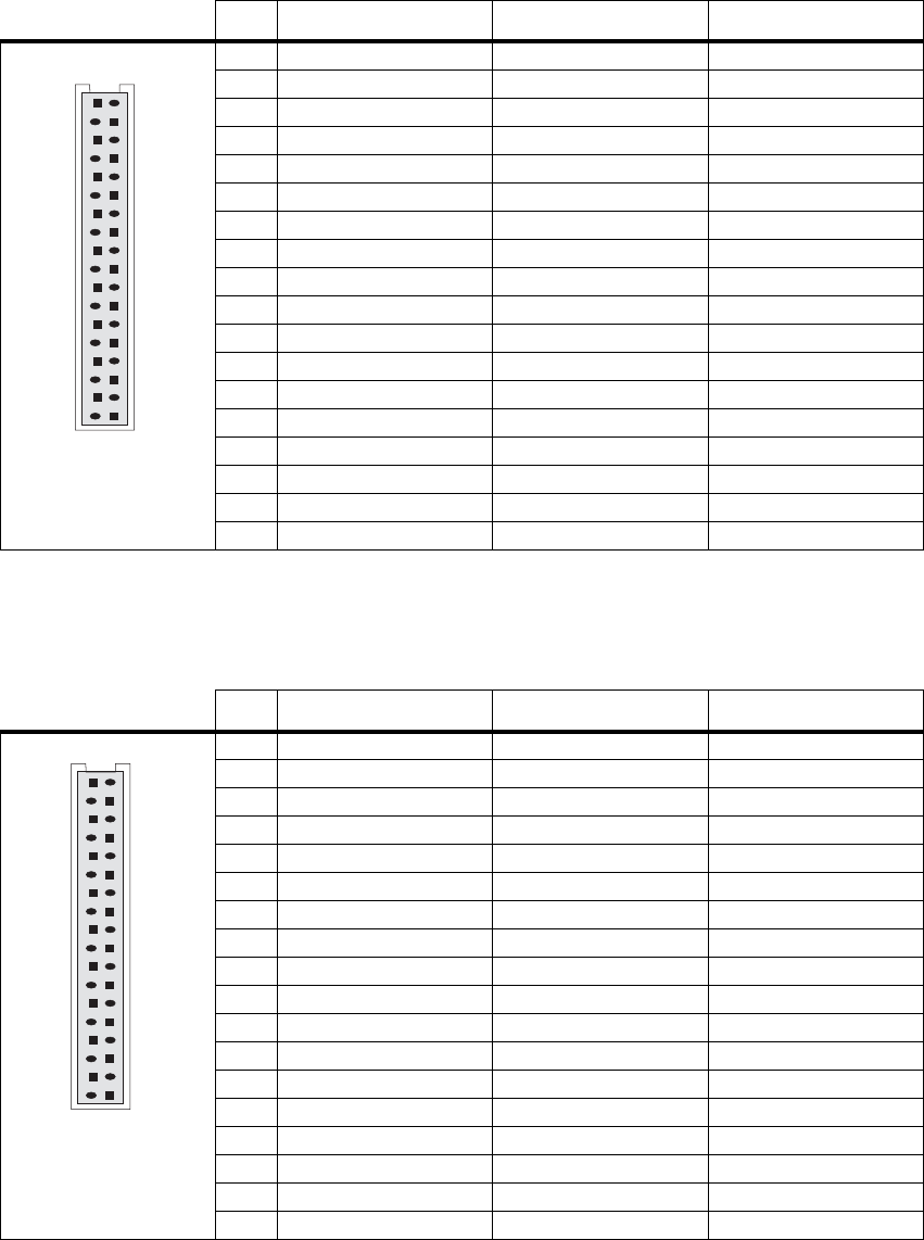
TB7100 Installation and Operation Manual Connections 75
© Tait Electronics Limited December 2005
6.2.3 UI Board Connectors
User Interface
Connector to
Transmitter
The user interface connector (SK1) to the transmitter is a 16-way
MicroMaTch connector.
.
User Interface
Connector to
Receiver
The user interface connector (SK2) to the receiver is a 16-way MicroMaTch
connector.
Pin Signal Name Signal Type Notes
1 TX_RX_AUD no connection no connection
2 TX_+13V8_SW no connection no connection
3 TX_CH_TXD output programming data
4 TX_CH_PTT output microphone PTT
5 TX_MIC_AUD_OUT output audio from microphone
6 TX_AGND ground analogue ground
7 TX_CH_RXD input programming data
8 TX_DGND ground digital ground
9 TX_CH_ON_OFF input digital ground
10 TX_VOL_WIP_DC output no connection
11 TX_CH_SPI_D0 input
12 TX_CH_LE input
13 TX_CH_SPIO1 input digital ground
14 TX_+3V3 no connection no connection
15 TX_CH_SPI_DI output
16 TX_CH_SPI_CLK input
17 TX_CH_SPK- no connection no connection
18 TX_CH_SPK+ no connection no connection
1
2
external view
Pin Signal Name Signal Type Notes
1 RX_RX_AUD no connection no connection
2 RX_+13V8_SW input +13V8DC for PCB
3 RX_CH_TXD output programming data
4 RX_CH_PTT no connection no connection
5 RX_MIC_AUD_OUT input no connection
6 RX_AGND ground analogue ground
7 RX_CH_RXD input programming data
8 RX_DGND ground digital ground
9 RX_CH_ON_OFF input digital ground
10 RX_VOL_WIP_DC output volume control
11 RX_CH_SPI_D0 input
12 RX_CH_LE input
13 RX_CH_GPIO1 input digital ground
14 RX_+3V3 input +3V3DC for PCB
15 RX_CH_SPI_DI output
16 RX_CH_SPI_CLK input
17 RX_CH_SPK- input speaker audio
18 RX_CH_SPK+ input speaker audio
external view
1
2
76 Connections TB7100 Installation and Operation Manual
© Tait Electronics Limited December 2005

TB7100 Installation and Operation Manual Preparation for Operation 77
© Tait Electronics Limited December 2005
7 Preparation for Operation
7.1 Introduction
The base station operation can be modified by the use of links and
programmable settings.
The base station can be configured for operation in the following basic
modes of operation:
■Line-controlled base: The base station transmit audio and key is derived
via the system interface. Audio response is link-selectable.
■Talk through repeater (voice): The receiver audio is directly connected
to the transmitter and the transmitter is keyed by the receiver gate.
Audio response in this mode is software-selectable.
■Data repeater: The received data line is connected to the transmit data
line. receiver gate and transmitter key signals are not used.
■RF modem: Data on the serial interface is connected to the transmitter
and the receiver.
■TaitNet trunking.
7.2 Mode of Operation
This section shows how to set up the base station for various modes of
operation.
Examples are:
■line-controlled base
■talk through repeater
■RF modem
■data repeater
■TaitNet trunking.
Where applicable, the procedure for setting any of the audio levels or other
adjustment points will be described, along with the procedure for measuring
a variety of parameters commonly monitored.
To verify the operation of the base station it is best to configure it as a line-
controlled base first. In this mode of operation the receiver and transmitter
modules can be independently tested because all the audio inputs and
outputs are accessible via the system interface connector. When the base
station has been tested as a line-controlled base, it is then a simple process to
change the links to the required mode of operation and perform any
additional functional testing required for that mode of operation.
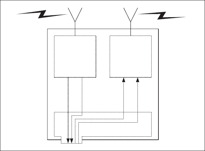
78 Preparation for Operation TB7100 Installation and Operation Manual
© Tait Electronics Limited December 2005
7.3 Line-controlled Base
In the line-controlled base mode the audio and control signals are routed
from the external 25-way D-range connector through the system interface
to the receiver and transmitter modules. External equipment is used to
control the operation of the base station.
7.3.1 Test Equipment Required
The following test equipment is used to setup the base station for line-
controlled base operation:
■TBA0STU calibration test unit (CTU) which includes the CTU adaptor
and CTU cable, or
■TBA0ST1 calibration test unit (CTU), TBB0STU-TBB CTU adaptor
(220-02068-xx) and CTU cable (219-02888-xx)
■PC, programming cables and the TB7100 programming application
■digital voltmeter
■DC power supply (not necessary with internal AC power supply unit
option)
■RF test set with:
■RF power meter
■modulation analyser
■RF signal generator
■sinad meter
■audio distortion meter
Figure 7.1 Line-controlled base
System Interface
Receiver Transmitter
RF In RF Out
Rx Audio
Rx Gate
Tx Audio
Tx Key

TB7100 Installation and Operation Manual Preparation for Operation 79
© Tait Electronics Limited December 2005
■audio level meter
■audio signal generator.
Calibration Test Unit
(CTU) The CTU is used to configure and test the base station. The same CTU is
used for TB8000 and TB9000 base station equipment, so only some of the
features on the CTU apply to the TB7100 base station. The CTU adaptor
is plugged into the system connector of the CTU. The CTU cable is
plugged into the system connector of the base station.
For more information on the CTU refer to the TBA0STU/TBA0STP
Calibration and Test Unit Operation Manual (MBA-00013-xx).
7.3.2 Test Equipment Setup
1. Connect the PC to the programming port on the front panel of the
base station. See “Connecting to the PC” on page 105.
2. Plug the adaptor into the system connector on the CTU. Connect the
adaptor cable to the system connector of the base station.
Note Connections between the CTU and the test equipment will vary
and are described in the relevant test steps.
3. Ensure all switches on the CTU are in the 1 or OFF position
(inactive).
4. Connect the receiver N-type connector to the RF test set (signal
generator) output port.
5. Connect the transmitter N-type connector to the RF test set (power
and modulation meter) input port, check the test set is rated for the
transmit power of the base station.
6. Connect the 13.8V power supply to the DC input on the base station,
ensuring correct polarity.

80 Preparation for Operation TB7100 Installation and Operation Manual
© Tait Electronics Limited December 2005
7.3.3 Link Settings
Remove the cover as detailed in “Removing the Base Station and Opening
the Tray” on page 54 and set the following links on the SI board.
Links of the mandatory settings must be in the position indicated. Links of
the optional settings must be in one of the positions listed. The defaults are
generally recommended.
Replace the cover as detailed in “Final Reassembly” on page 63.
Table 7.1 Line-controlled base—mandatory settings
LINK Name Pins Position Function Comments
J400 Tx Key
Source 3 1-2 Line-controlled Base mode External PTT signal to transmitter
J502 Tx Audio
Source 3 1-2 Line-controlled Base mode Balanced and unbalanced audio
inputs to transmitter
J503 Rx Audio
Destination 3 2-3 Line-controlled Base mode Received audio to balanced and
unbalanced audio outputs
W401
W402 TOI 9V Enable
TOI 4.5V Enable 2
2Not
fitted Tone on Idle disable Refer “Tone On Idle (TOI)” on
page 118 to enable idle tone.
Table 7.2 Line-controlled base—optional settings
LINK Name Pins Position Function Comments
J500 Line Out
Frequency
Response
31-2
2-3 Flat response
De-emphasis Default position is 2-3
J501 Line In
Frequency
Response
31-2
2-3 Flat response
De-emphasis Default position is 2-3
J507 Line In
Destination 31-2
2-3 Tx Line In to Aux Mic
Tx Line In to Audio Tap In Default position is 2-3.
Position 1-2 is usually used only
by trunking systems.
J206 Fan Control 1 3 1-2
2-3 Fan controlled by J207
Fan always on Default position is 1-2
J207 Fan Control 2 3 1-2
2-3 Fan Tx key-controlled
Fan temperature-controlled Default position is 2-3
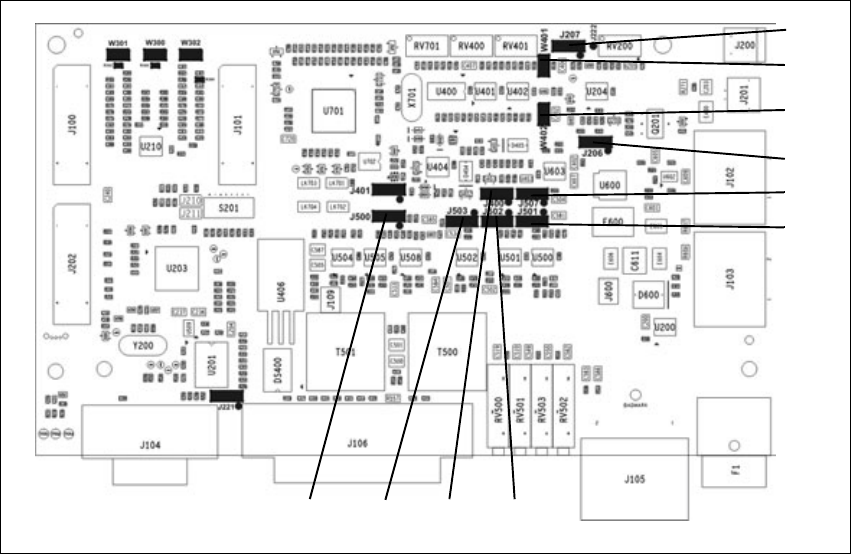
TB7100 Installation and Operation Manual Preparation for Operation 81
© Tait Electronics Limited December 2005
7.3.4 Applying Power
Before turning on the base station, check that:
■all looms and cables at the front and rear of the base station are fitted
correctly
■all connectors are secure
■the 20A fuse is fitted.
Turn on the power supply and check that the base station powers up
correctly:
■The power LED on the user interface lights up.
■The LCD indicates the current channel number.
Figure 7.2 System interface link positions
J400J500 J502J503
J207
W401
W402
J206
J507
J501
82 Preparation for Operation TB7100 Installation and Operation Manual
© Tait Electronics Limited December 2005
7.3.5 Programming
To program a base station for line-controlled base operation follow the
instructions below. Do not add CTCSS or any additional settings at this
stage. These are covered in “Programmable Features” on page 105. See
“Connecting to the PC” on page 105 before beginning.
Transmitter 1. Place the transmit/receive programming switch on the user interface
into the transmit position.
2. Read the transmitter or start with a new transmitter data file.
3. Use the reset to defaults command under the file menu to ensure all
the mandatory and recommended settings are in their correct default
states.
4. Open the specifications form and select the correct RF band, not
required if the transmitter file was read.
5. Open the channels form and add as many channels as are required.
For each channel enter the:
■transmit frequency
■Tx subaudible signalling value (leave as “None”)
■power level
■bandwidth.
6. Open the key settings form and select the required function for each
function key.
For example:
■FN1 = Preset Channel
■FN2 = Preset Channel
■FN3 = Preset Channel
■FN4 = None
7. Program the transmitter.
Receiver 1. Place the transmit/receive programming switch on the user interface
into the receive position.
2. Read the receiver or start with a new receiver data file.
3. Use the reset to defaults command under the file menu to ensure all
the mandatory and recommended settings are in their correct default
states.
4. Open the specifications form and select the correct RF band, not
required if the receiver file was read.
5. Open the channels form and add as many channels as are required.
For each channel enter:
TB7100 Installation and Operation Manual Preparation for Operation 83
© Tait Electronics Limited December 2005
■receive frequency
■Rx subaudible signalling value (leave as “None”)
■squelch setting
■bandwidth.
6. Open the key settings form and select the required function for each
function key.
For example:
■FN1 = Preset Channel (same as transmitter)
■FN2 = Preset Channel (same as transmitter)
■FN3 = Preset Channel (same as transmitter)
■FN4 = Monitor / Squelch override
7. Program the receiver.
7.3.6 Receiver Audio Level Adjustment
Unbalanced Line 1. Connect the unbalanced output from the CTU to the audio input
port on the test set and set up the test set to measure the audio level.
2. Set the RF signal generator to the correct RF frequency, modulated
with a 1kHz audio tone at 60% of full system deviation.
3. Set the RF output level to -70dBm.
4. Verify that the receiver gate opens and the busy LED turns on.
5. Adjust RV502 (UNBAL OUT) on the rear panel to set the
unbalanced output to the required level (typically 1Vp-p).
Balanced Line 1. Connect the line output from the CTU to the audio input port on
the test set and set up the test set to measure the audio level.
2. Turn the CTU 600 ohm switch on.
3. Set the RF signal generator to the correct RF frequency modulated
with a 1kHz audio tone at 60% of full system deviation.
4. Set the RF output level to -70dBm.
5. Verify that the receiver gate opens and the busy LED turns on.
6. Adjust RV503 (BAL OUT) on the rear panel to set the balanced
output to the required level (typically -10dBm).

84 Preparation for Operation TB7100 Installation and Operation Manual
© Tait Electronics Limited December 2005
7.3.7 Receiver Functional Testing
This section describes how to test some parameters which are commonly
monitored.
Sensitivity The sensitivity can be measured using either the balanced or unbalanced
audio output.
1. Connect the required audio output from the CTU to the audio input
port on the test set.
2. Connect the RF output from the test set to the Rx input on the rear
panel.
3. Set up the test set to measure the SINAD level.
4. Set the RF signal generator to the correct RF frequency, modulated
with a 1kHz audio tone at 60% of full system deviation.
5. Set the RF output level to -70dBm.
6. Verify that the receiver gate opens and the busy LED turns on.
7. Reduce the RF level until 12dB SINAD is obtained.
Note This level will vary depending on the bandwidth and frequency
response of the channel. Consult the specifications manual for val-
ues.
Note If the mute closes before 12dB SINAD is reached then squelch
override may be programmed to a function key.
Pressing this key will prevent the mute from closing.
RSSI Level 1. Connect a voltmeter to the RSSI test point on the CTU.
2. Set the RF signal generator to the correct RF frequency.
3. Set the RF level to -100dBm.
4. Verify the RSSI voltage is 1.1V±300mV.
Note If necessary adjust the RF level from –50dBm to –115dBm and
verify that the RSSI voltage changes at 25mV/dB.
Mute Thresholds The mute thresholds can be measured using either the balanced or
unbalanced output.
1. Connect the required audio output from the CTU to the audio input
port on the test set.
2. Set up the test set to measure the SINAD level.

TB7100 Installation and Operation Manual Preparation for Operation 85
© Tait Electronics Limited December 2005
3. Set the RF signal generator to the correct RF frequency, modulated
with a 1kHz audio tone at 60% of full system deviation.
4. Set the RF output level to –70dBm.
5. Verify that the receiver gate opens and the busy LED turns on.
6. Reduce the RF level until the mute closes. This RF level is the mute
close threshold.
7. Increase the RF level until the mute opens. This RF level is the mute
open threshold.
8. The difference between these two levels is the mute hysteresis.
Note The mute thresholds are determined by the squelch setting pro-
grammed in the receiver’s channel table.
Note If the thresholds are not suitable use the calibration application to
change the squelch setting on the channel table.
Distortion The Rx Distortion can be measured using either the balanced or unbalanced
output.
Note Before beginning this test verify the test set is rated to handle the
transmit power being tested.
1. Connect the required audio output from the CTU to the audio input
port on the test set.
2. Set up the test set to measure the distortion level.
3. Set the RF signal generator to the correct RF frequency, modulated
with a 1kHz audio tone at 60% of full system deviation.
4. Set the RF output level to –70dBm.
5. The measured distortion level should be within the receiver
specifications as detailed in the specifications manual.
7.3.8 Transmitter Audio Level Adjustment
Balanced Line 1. Set up the test set to measure the transmitter modulation level.
2. Connect the CTU line input to the audio output port on the test set.
3. Set up the test set audio output to be 1kHz at the required line level
(typically –10dBm).
4. Activate the Tx Key switch and verify that the transmission is at the
programmed power and frequency.

86 Preparation for Operation TB7100 Installation and Operation Manual
© Tait Electronics Limited December 2005
5. Adjust RV500 (BAL IN) on the rear panel to the required deviation
(typically 60% of full system deviation).
Unbalanced Line 1. Set up the test set to measure the transmitter modulation level.
2. Connect the CTU unbalanced input to the audio output port on the
test set.
3. Set up the test set audio output to be 1kHz at the required line level
(typically 1Vp-p).
4. Activate the Tx Key switch and verify that the transmission is at the
programmed power level and frequency.
5. Adjust RV501 (UNBAL IN) on the rear panel to the required
deviation (typically 60% of full system deviation).
7.3.9 Transmitter Functional Testing
This section describes how to test some parameters commonly found on RF
channel test sheets.
Tx Power and
Frequency 1. Set up the test set to measure frequency and power level.
2. Activate the Tx Key switch on the CTU.
3. Verify that the measured power level and frequency match the
programmed settings, within the expected accuracy of the test set and
taking into account cable losses.
Note If the measured value does not agree with the programmed set-
tings, the transmitter module is either faulty or needs recalibrating.
Audio Distortion When measuring the transmitter audio distortion, the audio input signal can
be via either the balanced or unbalanced audio input.
1. Connect the audio output from the test set to the required CTU
audio input.
2. Set up the modulation analyser in the test set to measure the
distortion of the modulated audio signal.
3. Set up the test set audio generator output to be 1kHz and at the level
required to produce 60% full system deviation (this is the same level
used in the audio level adjustment section).
4. Activate the Tx Key switch and verify that the measured deviation is
60% of full system deviation.
5. The measured distortion level should be within the transmitter
specifications as detailed in the specifications manual.

TB7100 Installation and Operation Manual Preparation for Operation 87
© Tait Electronics Limited December 2005
Note If the measured value does not agree with the programmed set-
tings, the transmitter module is either faulty or needs recalibrating.
Maximum
Deviation When measuring the maximum deviation, the audio input signal can be via
either the balanced or unbalanced audio input.
If CTCSS is to be added, this should be done before carrying out this test.
Refer to “Enabling Subaudible Signalling” on page 115 for instructions.
1. Set up the test set to measure the deviation of the RF signal.
2. Connect the audio output from the test set to the required CTU
audio input.
3. Set up the test set audio generator output to be 1kHz and at the
required level to produce 60% full system deviation (this is the level
used in the audio level adjustment section).
4. Activate the Tx Key switch and verify that the measured deviation is
60% of full system deviation.
5. Increase the test set audio generator output level by 20dB and sweep
the audio frequency from 100Hz to 4kHz.
6. The maximum measured deviation level should not exceed the full
system deviation programmed for the channel.
Note If the measured value exceeds the programmed settings, the trans-
mitter module is either faulty or needs recalibrating.
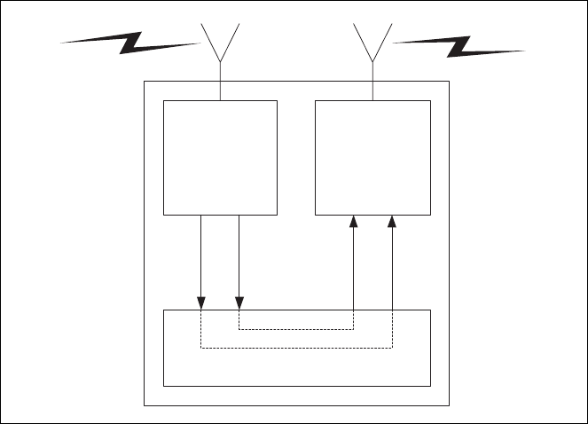
88 Preparation for Operation TB7100 Installation and Operation Manual
© Tait Electronics Limited December 2005
7.4 Talk Through Repeater
Once the base station has been set up and tested as a line-controlled base, it
is simple to convert it into a talk through repeater. In this mode of operation
the received audio and receiver gate from the receiver module are looped
back to the transmitter.
7.4.1 Test Equipment Required
The following test equipment is used to setup the base station for talk
through repeater operation:
■PC, programming cables and the TB7100 programming application
■digital voltmeter
■DC power supply
■RF test set with:
■RF power meter
■modulation analyser
■RF signal generator
■sinad meter
■audio distortion meter
■audio level meter
■audio signal generator.
Figure 7.3 Talk through repeater
Receiver Transmitter
System Interface
RF In RF Out
Rx Audio
Rx Gate
Tx Audio
Tx Key

TB7100 Installation and Operation Manual Preparation for Operation 89
© Tait Electronics Limited December 2005
7.4.2 Test Equipment Setup
1. Connect the PC to the programming port on the front panel of the
base station. See “Connecting to the PC” on page 105.
2. Connect the receiver N-type connector to the RF test set (signal
generator) output port.
3. Connect the transmitter N-type connector to the RF test set (power
and modulation meter) input port, check the test set is rated for the
transmit power of the base station.
4. Connect the 13.8V power supply to the DC input on the base station,
ensuring correct polarity.
7.4.3 Link Settings
Remove the cover as detailed in “Removing the Base Station and Opening
the Tray” on page 54 and set the following links on the SI board.
Links of the mandatory settings must be in the position indicated. Links of
the optional settings must be in one of the positions listed. The defaults are
generally recommended.
Replace the cover as detailed in “Final Reassembly” on page 63.
Table 7.3 Talk through repeater—mandatory settings
LINK Name Pins Position Function Comments
J400 Tx Key
Source 3 2-3 Talk Through Repeater
mode Receiver gate keys transmitter
J502 Tx Audio
Source 3 2-3 Talk Through Repeater
mode Transmitter audio taken from the
receiver
J503 Rx Audio
Destination 3 1-2 Talk Through Repeater
mode Received audio to the transmitter
W401
W402 TOI 9V Enable
TOI 4.5V Enable 2
2Not
fitted Tone on Idle disable Tone on idle not used in repeater
configuration
Table 7.4 Talk through repeater—optional settings
LINK Name Pins Position Function Comments
J507 Line In
Destination 31-2
2-3 Tx Line In to Aux Mic
Tx Line In to Audio Tap In Default position is 2-3
J206 Fan Control 1 3 1-2
2-3 Fan controlled by J207
Fan always on Default position is 1-2
J207 Fan Control 2 3 1-2
2-3 Fan Tx key-controlled
Fan temperature-controlled Default position is 2-3
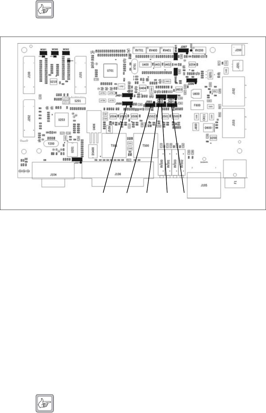
90 Preparation for Operation TB7100 Installation and Operation Manual
© Tait Electronics Limited December 2005
Note By default the audio frequency response will be flat.
7.4.4 Applying Power
Before turning on the base station, check that:
■all looms and cables at the front and rear of the base station are fitted
correctly
■all connectors are secure
■the 20A fuse is fitted.
Turn on the power supply and check that the base station powers up
correctly:
■The power LED on the user interface lights up.
■The LCD indicates the current channel number.
7.4.5 Programming
No changes to the values programmed for line-controlled base operation are
required. See “Programming” on page 82 for details.
Note If a soft tail setting is required see later in this chapter “Soft Off
(Tx Tail Time)” on page 118.
Figure 7.4 System interface link positions
J400J500 J502J503 J501

TB7100 Installation and Operation Manual Preparation for Operation 91
© Tait Electronics Limited December 2005
7.4.6 Audio Level Adjustment
There is no audio level adjustment necessary in repeater mode. The internal
linking is designed to produce a repeater with no talk through gain. If talk
through gain is required it can be implemented by linking back the audio
using a DB25 connector on the system interface and setting the audio levels
as required, see “Alternate Talk Through Repeater Configuration” on
page 92 for a more detailed explanation.
7.4.7 Talk Through Repeater Functional Testing
The basic operation of the base station has already been tested as a line-
controlled base. This section describes the additional functional tests
required to verify that the base station is operating correctly as a repeater.
Repeater Key With the test set in duplex mode:
1. Set up the test set to measure the transmitter power and frequency
output.
2. Set the RF signal generator to the correct frequency for the receiver.
Note If subaudible signalling has been added, also modulate the carrier
with the required signal.
3. Set the RF level to -70dBm.
4. The receiver busy LED turns on and the transmitter keys up and
transmits at the programmed power level and frequency. When the
RF source is removed, the transmitter will stop transmitting.
Talk Through With the test set in duplex mode:
1. Set up the test set to measure the modulation level and frequency.
2. Set the RF signal generator to the correct frequency for the receiver.
3. Modulate the RF carrier with a 1kHz audio tone at 60% full system
deviation.
Note If subaudible signalling has been added, also modulate the carrier
with the required signal.
4. Set the RF level to –70dBm.
5. The receiver busy LED turns on and the transmitter keys up and
transmits at the programmed power level and frequency.
The transmitted signal will be the same as received. If subaudible
signalling has been enabled, the required sub-tone will also be
transmitted.
6. Ensure the deviation is at the desired level.

92 Preparation for Operation TB7100 Installation and Operation Manual
© Tait Electronics Limited December 2005
7.4.8 Alternate Talk Through Repeater Configuration
Audio Frequency
Response When a talk through repeater is created by linking the audio path using links
J502 and J503, the default frequency response is flat audio. The pre/de-
emphasis links J500 and J501 are not in the audio path and have no effect.
Repeater Talk
Through Gain When a talk through repeater is created by linking the audio path using links
J502 and J503, the repeater will have no talk through gain. If talk through
gain is required internally link the base station for line-controlled base
operation. Then externally configure it to operate as a repeater by linking
the following pins on a 25pin male D-range connector and plugging the
connector into the system connector on the rear panel of the base station.
When configured as described above:
■The base station will operate as a repeater.
■The Talk through gain can be set by adjusting the line output level and
line input sensitivity RV500 (BAL IN) and RV503 (BAL OUT) on the
rear panel.
■The pre/de emphasis links J500 and J501 can be used to set the audio
frequency response.
Pins Function
1 to 5 Rx Line Out+ to Tx Line In+
4 to 8 Rx Line Out- to Tx Line In-
14 to 15 Rx Gate to Tx Key
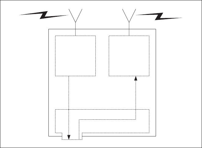
TB7100 Installation and Operation Manual Preparation for Operation 93
© Tait Electronics Limited December 2005
7.5 RF Modem
In RF modem mode the transmitter and receiver are connected to the serial
interface and any data on the serial interface is transmitted. Any data
received is forwarded to the PC.
7.5.1 Test Equipment Required
The following test equipment is used to setup the base station for RF
modem operation:
■TBA0STU calibration test unit (CTU) which includes the CTU adaptor
and CTU cable, or
■TBA0ST1 calibration test unit (CTU), TBB0STU-TBB CTU adaptor
(220-02068-xx) and CTU cable (219-02888-xx)
■PC, programming cables and the TB7100 programming application
■digital voltmeter
■DC power supply
■RF test set with:
■RF power meter
■modulation analyser
■RF signal generator
■sinad meter
■audio distortion meter
■audio level meter
■audio signal generator
Figure 7.5 RF modem
Serial Interface
Receiver Transmitter
RF In RF Out
Rx Data
Tx Data

94 Preparation for Operation TB7100 Installation and Operation Manual
© Tait Electronics Limited December 2005
Calibration Test Unit
(CTU) The CTU is used to configure and test the base station. The same CTU is
used for TB8000 and TB9000 base station equipment, so only some of the
features on the CTU apply to the TB7100 base station. The CTU adaptor
is plugged into the system connector of the CTU. The CTU cable is
plugged into the system connector of the base station.
For more information on the CTU refer to the TBA0STU/TBA0STP
Calibration and Test Unit Operation Manual (MBA-00013-xx).
7.5.2 Test Equipment Setup
1. Connect the PC to the programming port on the front panel of the
base station. See “Connecting to the PC” on page 105.
2. Connect the receiver N-type connector to the RF test set (signal
generator) output port.
3. Connect the transmitter N-type connector to the RF test set (power
and modulation meter) input port, check the test set is rated for the
transmit power of the base station.
4. Connect the 13.8V power supply to the DC input on the base
station, ensuring correct polarity.
7.5.3 Link Settings
Remove the cover as detailed in “Removing the Base Station and Opening
the Tray” on page 54 and set the following links on the SI board.
Links of the mandatory settings must be in the position indicated. Links of
the optional settings must be in one of the positions listed. The defaults are
generally recommended.
Replace the cover as detailed in “Final Reassembly” on page 63.
Table 7.5 RF modem—mandatory settings
LINK Name Pins Position Function Comments
J221 RS232 Loop
Back 3 1-2 RS-232 out data connector
J400 Tx Key
Source 3 1-2 External Tx key source Use this setting because the
transmitter will automatically key
up when there is data to send so
should not be keyed by the
receiver gate.
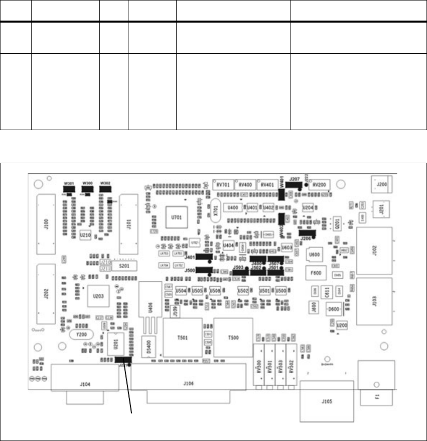
TB7100 Installation and Operation Manual Preparation for Operation 95
© Tait Electronics Limited December 2005
7.5.4 Applying Power
Before turning on the base station, check that:
■all looms and cables at the front and rear of the base station are fitted
correctly
■all connectors are secure
■the 20A fuse is fitted.
Turn on the power supply and check that the base station powers up
correctly:
■The power LED on the user interface lights up.
■The LCD indicates the current channel number.
Table 7.6 RF modem—optional settings
LINK Name Pins Position Function Comments
J206 Fan Control 1 3 1-2
2-3 Fan controlled by J207
Fan always on Default position is 1-2
J207 Fan Control 2 3 2-3 Fan temperature-controlled Do not use position 1-2 (Tx key-
activated fan). The transmitter will
automatically key up when there
is data to send. This will not
activate the Tx key line and
therefore will not activate the fan.
Figure 7.6 System interface link positions
J221
96 Preparation for Operation TB7100 Installation and Operation Manual
© Tait Electronics Limited December 2005
7.5.5 Programming
Please see the line-controlled base “Programming” on page 82 for details on
how to program the base station for RF modem operation.
7.5.6 Audio Level Adjustment
In this configuration the system interface connector is not used, so it is not
necessary to set the line output level or line input sensitivity.
7.5.7 Programming for FFSK Operation
To program a base station for FFSK operation:
Transmitter 1. Read the transmitter or start with a new transmitter data file.
2. Use the reset to defaults command under the file menu to ensure all
the mandatory and recommended settings are in their correct default
states.
3. Open the specifications form and select the correct RF band
4. Open the channels form summary tab. Add as many channels as are
required and for each channel enter the following:
■transmit frequency
■Tx subaudible signalling value
■power level
■bandwidth.
5. Open the channels form details tab and for each channel check the
Use channel for data check box.
6. Open the key settings form and select the required function for each
function key. For example:
■FN1 = Preset Channel
■FN2 = Preset Channel
■FN3 = Preset Channel
■FN4 = None.
7. Open the data form and in the general tab:
■In the command mode section disable all check boxes.
■In the transparent mode section select transparent mode enabled
and de-select the other check boxes.
■Set Power Up State to FFSK transparent mode.
8. Open the data form and in the serial communications tab:
■In the serial communications setup field set the FFSK transparent
TB7100 Installation and Operation Manual Preparation for Operation 97
© Tait Electronics Limited December 2005
mode baud rate to 1200, the Flow control to None and the data
port to the required data port.
■Ensure hardware flow control is set to None.
9. Open the data form RF modems tab. The THSD modem settings do
not apply and can be ignored. In the FFSK modem section set up the
following:
■Ignore CTCSS/DCS can be disabled (CTCSS/DCS is not used
in this example).
■Enable Check Packet Length.
■Disable FFSK Tone Blanking.
■FFSK Lead-In Delay default of 500ms is suitable but can be
changed.
■FFSK Lead-Out Delay default of 200ms is suitable but can be
changed.
10. Program the transmitter
Receiver 1. Read the receiver or start with a new receiver data file.
2. Use the reset to defaults command under the file menu to ensure all
the mandatory and recommended settings are in their correct default
states.
3. Open the specifications form and select the correct RF band.
4. Open the channels form summary tab. Add as many channels as are
required and for each channel enter the following:
■receive frequency
■Rx subaudible signalling value
■squelch setting
■bandwidth.
5. Open the channels form details tab and for each channel check the
use channel for data check box.
6. Open the key settings form and select the required function for each
function key. For example:
■FN1 = Preset Channel (same as transmitter)
■FN2 = Preset Channel (same as transmitter)
■FN3 = Preset Channel (same as transmitter)
■FN4 = Monitor / Squelch override
7. Open the data form and in the general tab:
■In the command mode section disable all check boxes.
■In the transparent mode section select transparent mode enabled
and de-select the other check boxes.
■Set Power Up State to FFSK transparent mode.
98 Preparation for Operation TB7100 Installation and Operation Manual
© Tait Electronics Limited December 2005
8. Open the data form and in the serial communications tab:
■In the serial communications setup field set the FFSK transparent
mode baud rate to 1200, the Flow control to None and the data
port to the required data port.
■Ensure hardware flow control is set to None.
9. Open the data form RF modems tab. The THSD modem settings do
not apply and can be ignored. In the FFSK modem section set up the
following:
■Ignore CTCSS/DCS can be disabled (CTCSS/DCS is not used
in this example).
■Enable Check Packet Length.
■Disable FFSK Tone Blanking.
■FFSK Lead-In Delay default of 500ms is suitable but can be
changed.
■FFSK Lead-Out Delay default of 200ms is suitable but can be
changed.
10. Program the receiver.
7.5.8 Programming for THSD Operation
Transmitter 1. Read the transmitter or start with a new transmitter data file.
2. Use the reset to defaults command under the file menu to ensure all
the mandatory and recommended settings are in their correct default
states.
3. Open the specifications form and select the correct RF band.
4. Open the channels form summary tab. Add as many channels as are
required and for each channel enter the following:
■transmit frequency
■Tx subaudible signalling value = Ignored in THSD Mode
■power level
■bandwidth.
5. Open the channels form details tab and for each channel check the
use channel for data check box.
6. Open the key settings form and select the required function for each
function key. For example:
■FN1 = Preset Channel
■FN2 = Preset Channel
■FN3 = Preset Channel
■FN4 = None
TB7100 Installation and Operation Manual Preparation for Operation 99
© Tait Electronics Limited December 2005
7. Open the data form and in the general tab:
■In the command mode section disable all check boxes.
■In the transparent mode section select transparent mode enabled
and THSD modem enabled and de-select the ignore escape
sequence check box.
■Set Power Up State to THSD transparent mode.
8. Open the data form and in the serial communications tab:
■In the serial communications setup field set the THSD transparent
mode baud rate to 9600, the Flow control to None and the data
port to the required data port.
■Ensure hardware flow control is set to None.
9. Open the data form RF modems tab. The FFSK modem settings do
not apply and can be ignored. In the THSD modem section set up
the following:
■Wide band modem enabled
■Layer 2 Protocol enabled
■Forward Error Correction disabled
■THSD Lead-in Delay default of 30ms is acceptable.
10. Program the transmitter.
Receiver 1. Read the receiver or start with a new receiver data file.
2. Use the reset to defaults command under the file menu to ensure all
the mandatory and recommended settings are in their correct default
states.
3. Open the specifications form and select the correct RF band.
4. Open the channels form summary tab. Add as many channels as are
required and for each channel enter the following:
■receive frequency
■Rx subaudible signalling value = Ignored in THSD Mode
■squelch setting
■bandwidth.
5. Open the channels form details tab and for each channel check the
use channel for data check box.
6. Open the key settings form and select the required function for each
function key. For example:
■FN1 = Preset Channel (same as transmitter)
■FN2 = Preset Channel (same as transmitter)
■FN3 = Preset Channel (same as transmitter)
■FN4 = Monitor / Squelch override.
100 Preparation for Operation TB7100 Installation and Operation Manual
© Tait Electronics Limited December 2005
7. Open the data form and in the general tab:
■In the command mode section disable all check boxes.
■In the transparent mode section select transparent mode enabled
and THSD modem enabled and de-select the ignore escape
sequence check box.
■Set Power Up State to THSD transparent mode.
8. Open the data form and in the serial communications tab:
■In the serial communications setup field set the THSD transparent
mode baud rate to 9600, the Flow control to None and the data
port to the required data port.
■Ensure hardware flow control is set to None.
9. Open the data form RF modems tab. The FFSK modem settings do
not apply and can be ignored. In the THSD modem section set up
the following:
■Wide band modem enabled
■Layer 2 Protocol enabled
■Forward Error Correction disabled
■THSD Lead-In Delay default of 30ms is acceptable.
10. Program the receiver.
7.5.9 Verification
In order to verify the correct operation as an RF modem a basic functional
test can be carried out by sending data between the TB7100 base station and
a TM8000 mobile radio.
The following equipment will be required:
■DC power supply
■antenna for receiver input
■dummy load for transmitter output
■a PC running the terminal application connected to the serial data port
on the base station with a 9-pin serial cable
■a second PC running the terminal application connected to a TM8000
mobile radio which has been programmed to send and receive the
required data modulation (FFSK or THSD).
The test setup is shown in “RF modem test setup” on page 101.
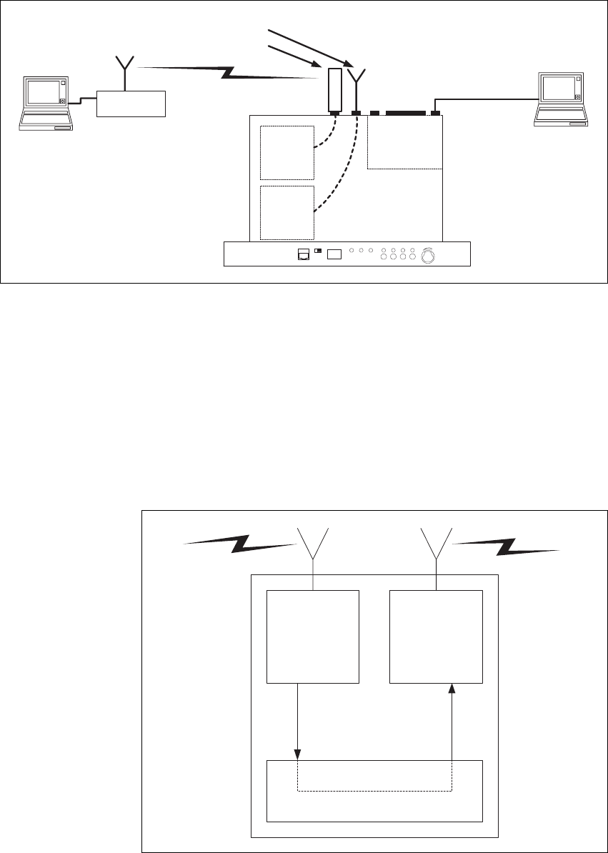
TB7100 Installation and Operation Manual Preparation for Operation 101
© Tait Electronics Limited December 2005
The correct operation of the base station as an RF modem can be verified
by transferring text files between the two PCs.
7.6 Data Repeater
In data repeater mode the base station will transmit all valid received data.
Figure 7.7 RF modem test setup
Receiver
Transmitter System Interface Terminal
Application
Dummy Load
Antenna
Terminal
Application
TM8000 Mobile
Radio
PROG/MIC Tx/Rx CHANNEL POWER Tx BUSY F1 F3 F4F2 VOLUME
Figure 7.8 Data repeater
Receiver Transmitter
System Interface
RF In RF Out
Rx Data
Tx Data

102 Preparation for Operation TB7100 Installation and Operation Manual
© Tait Electronics Limited December 2005
7.6.1 Link Settings
Remove the cover as detailed in “Removing the Base Station and Opening
the Tray” on page 54 and set the following links on the SI board.
Links of the mandatory settings must be in the position indicated. Links of
the optional settings must be in one of the positions listed. The defaults are
generally recommended.
Replace the cover as detailed in “Final Reassembly” on page 63.
Table 7.7 Data repeater—mandatory settings
LINK Name Pins Position Function Comments
J221 RS232 Loop
Back 3 2-3 RS-232 looped back
J400 Tx Key
Source 3 1-2 External Tx key source Use this setting because the
transmitter will automatically key
up when there is data to send so
should not be keyed by the
receiver gate.
Table 7.8 Data repeater—optional settings
LINK Name Pins Position Function Comments
J206 Fan Control 1 3 1-2
2-3 Fan controlled by J207
Fan always on Default position is 1-2
J207 Fan Control 2 3 2-3 Fan temperature-controlled Do not use position 1-2 (Tx key-
activated fan). The transmitter will
automatically key up when there
is data to send. This will not
activate the Tx key line and
therefore will not activate the fan.
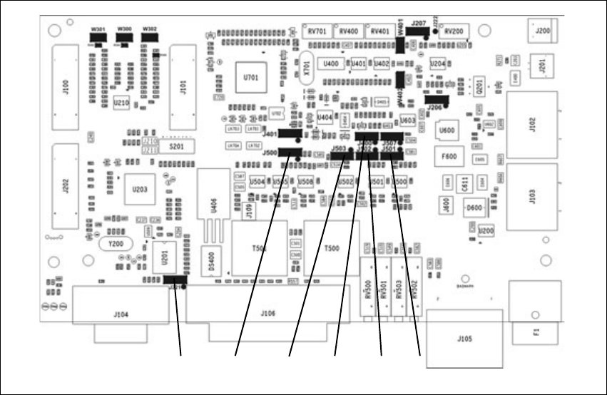
TB7100 Installation and Operation Manual Preparation for Operation 103
© Tait Electronics Limited December 2005
7.6.2 Applying Power
Before turning on the base station, check that:
■all looms and cables at the front and rear of the base station are fitted
correctly
■all connectors are secure
■the 20A fuse is fitted.
Turn on the power supply and check that the base station powers up
correctly:
■The power LED on the user interface lights up.
■The LCD indicates the current channel number.
7.6.3 Programming
Please see the line-controlled base “Programming” on page 82 for details on
how to program the base station for RF modem operation.
7.6.4 Audio Level Adjustment
In this configuration the system interface connector is not used, so it is not
necessary to set the line level or line Sensitivity.
Figure 7.9 System interface link positions
J400J500 J502J503 J501J221
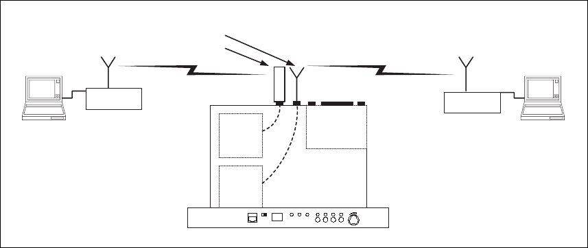
104 Preparation for Operation TB7100 Installation and Operation Manual
© Tait Electronics Limited December 2005
7.6.5 Data Repeater Functional Testing
In order to verify the correct operation as a data repeater a basic functional
test can be carried out. This involves sending data from one TM8000 mobile
radio to another TM8000 through the TB7100 base station.
The following equipment will be required:
■DC power supply
■antenna for receiver input
■dummy load for transmitter output
■two TM8000 mobile radios capable of sending and receiving the
required data format.
■two PCs running the terminal application.
■programming cables for the TM8000 mobile radios.
The test set-up is shown in Figure 7.10 on page 104.
The correct operation of the base station as an RF modem can be verified
by transferring text files between the two PCs.
7.7 TaitNet Trunking
The TB7100 base station can be configured to work with a T1810 or T1711
to form part of a TaitNet MPT1327 Trunking System.
For more information, refer to the technical note TN-1033-AN “Using the
Tait TB7100 in TaitNet MPT1327 Trunked Networks” available from
http://support.taitworld.com.
Figure 7.10 Data repeater test setup
Receiver
Transmitter System Interface
Dummy Load
Antenna
TM8000 Mobile
Radio
PROG/MIC Tx/Rx CHANNEL POWER Tx BUSY F1 F3 F4F2 VOLUME
TM8000 Mobile
Radio
Terminal
Application Terminal
Application

TB7100 Installation and Operation Manual Preparation for Operation 105
© Tait Electronics Limited December 2005
7.8 Programmable Features
The programmable features are applied to the transmitter and receiver
modules by using the TB7100 programming application.
7.8.1 Connecting to the PC
1. Plug the TPA-SV-006 or T2000-A19 programming lead into the
RS-232 serial port on a PC.
Note A USB-to-RS-232 adaptor can be used if the PC does not have a
built in serial port.
2. Connect the TMAA20-04 adaptor cable (RJ12 socket to RJ45 plug)
to the RJ12 plug on the TPA-SV-006 or T2000-A19 programming
lead.
3. Plug the RJ45 plug on the TMAA20-04 adaptor cable into the
PROG/MIC connector located on the front panel of the base station.
Select whether the TB7100 programming application communicates with
the transmitter or receiver module by using the receiver/transmitter
programming switch located on the user interface next to the PROG/MIC
connector.
7.8.2 TB7100 Programming Application
The TB7100 programming application allows the configuration parameters
of receiver or transmitter to be read out of a module, edited and written back
into the module. It is also possible the save the data files, so if a module ever
needs to be replaced, the previously saved data file can be programmed into
the new module. The model toolbar, indicates whether the data file is for a
receiver or transmitter module.
Appearance The TB7100 programming application has been optimised for mouse
navigation. Most features can be easily enabled and configured using a check
box or drop down list and the frequencies for each channel are simply typed
into a table.

106 Preparation for Operation TB7100 Installation and Operation Manual
© Tait Electronics Limited December 2005
Separate Data Files The base station has separate transmitter and receiver modules, which are
independently programmed with their required settings. This means that the
base station will have two data files, one for the transmitter and one for the
receiver.
New Data Files The reset to defaults feature in the TB7100 programming application makes
it easy to create a new data file. The required module type (receiver or
transmitter) is selected by pressing the appropriate button on the radio
model toolbar. The reset to defaults feature under the file menu is used to
reset all the settings to their default states. This ensures all the mandatory and
recommended settings are correct before starting to create a new data file.
The customer-specific settings for the current application are entered. reset
to defaults only affects the currently active radio model, so the correct radio
model must be selected first. If “reset to defaults” is greyed out, then the
settings are already in their default states.
Existing Data Files An existing data file can be read out of a transmitter or receiver module or
loaded from file. The radio model toolbar in the TB7100 programming
application will automatically update when a data file is loaded or read out
of a module to indicate whether the file is for a receiver or transmitter
module. The file can then be edited and saved or programmed back into the
module.
Note It is possible to read the receiver module and then the transmitter
module and have both data files loaded at the same time. The radio
model toolbar can then be used to toggle between the two data
files.When editing is complete, it is important to ensure the
receiver/transmitter programming switch position matches the
currently active data file before programming the module.
Feature Function
Menus Located along the top of the screen, these allow the user to
perform functions such as opening or saving data files, and
reading or programming the modules.
Toolbar Located just below the menu bar, the toolbar allows easy
access to the most commonly used menu items.
Radio Model Toolbar Located just below the toolbar, this indicates whether a newly
loaded file type is for a receiver or transmitter module. It also
allows the required module type to be selected when a new
data file is being created.
Forms Tree Located on the left side of the screen, the Forms Tree lists all
the forms that are available for editing.
Forms Displayed beside the Forms Tree is the Active Form.
The TB7100 programming application is made up of several
Forms (a page of parameters). All the configuration
parameters related to a particular feature are grouped
together in one form. Each form is intuitively labelled and
easily accessible from a Forms Tree

TB7100 Installation and Operation Manual Preparation for Operation 107
© Tait Electronics Limited December 2005
7.8.3 Mandatory Settings
The mandatory settings must not be changed from their default states or the
base station will not operate correctly. The mandatory settings in the
receiver module are not the same as those in the transmitter module.
The reset to defaults feature in the TB7100 programming application will
ensure all mandatory settings are correct for the selected module type.
The mandatory settings are not locked out. It is possible to change a
mandatory setting from its required state.
Receiver Mandatory
Settings The mandatory settings for the receiver are shown below. If these change,
the receiver will no longer operate.
Form Tab Item Name Setting
Data General Output SDMs Automatically Disabled
Data Serial Communications Data_Port AUX
Data Serial Communications XON_Character 11
Data Serial Communications XOFF_Character 13
Basic Settings Basic Network Settings TX Timer Duration 1
Basic Settings Basic Network Settings TX Lockout Duration 250
Basic Settings Sub Audible Signalling CTCSS Lead Out Delay 0
Basic Settings Sub Audible Signalling Invert Tx DCS Disabled
Basic Settings Sub Audible Signalling DCS Lead Out Delay 0
Channels Detailed TX_Frequency 000.000000
Channels Detailed TX Sig none
Channels Detailed Power off
UI Preferences User Interface Confidence Tones Disabled
UI Preferences User Interface Silent Mode Disabled
UI Preferences Audible Indicators Enabled All Disabled
Startup Startup Power On Mode Power on
Startup Startup Reset On Error Enabled
PTT MIC PTT PTT Priority high
PTT MIC PTT Audio Source CH MIC
PTT External PTT 1 PTT Transmission Type none
PTT External PTT 1 PTT Priority medium
PTT External PTT 1 Audio Source CH MIC

108 Preparation for Operation TB7100 Installation and Operation Manual
© Tait Electronics Limited December 2005
Transmitter
Mandatory Settings The mandatory settings for the transmitter are shown below, if these change
the transmitter will no longer operate.
7.8.4 User-defined Settings
The user-defined settings are specific to the customers application. These are
the only settings that need to be changed when configuring a base station
for operation. To set up a basic voice repeater or base station only the
channel information needs to be entered:
■frequency
■power level
■bandwidth
■squelch threshold
■sub-audible signalling.
If the system is to be used for data then the data parameters also need to be
set correctly:
■baud rate
■flow control
■error correction.
Form Tab Item Name Setting
Data General Output SDMs Automatically Disabled
Data Serial Communications Data_Port AUX
Data Serial Communications XON_Character 11
Data Serial Communications XOFF_Character 13
Basic Settings Sub Audible Signalling Invert Rx DCS Disabled
Channels Detailed RX_Frequency 000.000000
Channels Detailed RX Sig none
Channels Detailed Squelch hard
UI Preferences User Interface Confidence Tones Disabled
UI Preferences User Interface Silent Mode Disabled
UI Preferences Audible Indicators Enabled All Disabled
Startup Startup Power On Mode Power on
Startup Startup Reset On Error Enabled
PTT MIC PTT PTT Priority high
PTT MIC PTT Audio Source CH Mic
PTT External PTT 1 PTT Priority medium
PTT External PTT 1 Audio Source Audio Tap In

TB7100 Installation and Operation Manual Preparation for Operation 109
© Tait Electronics Limited December 2005
Receiver User-
defined Settings The user-defined settings for the receiver are shown below. The cells in grey
denote that the value should stay as detailed because of other constraining
settings.
Form Tab Item Name Value Range Recommended
Data General Transparent Mode
Enabled Enabled / Disabled Enabled
Data General THSD_Modem_
Enabled Enabled / Disabled Enabled
Data Serial Communications FFSK_Transparent_
Mode_Baudrate 1200, 2400, 4800, 9600,
14400, 19200, 28800 19200
Data Serial Communications THSD_Transparent_
Mode_Baudrate 1200, 2400, 4800, 9600,
14400, 19200, 28800 19200
Basic Settings Basic Network Settings Squelch Detect Type Noise level, Signal strength Noise Level
Basic Settings Sub Audible Signalling Invert Rx DCS Enabled, Disabled Disabled
Channels Detailed RX_Frequency 000.000000…
999.999999 000.000000
Channels Detailed RX Sig CTCSS tone OR DCS tone none
Channels Detailed Network 1…4 1
Channels Detailed Bandwidth 12.5, 20, 25 12.5
Channels Detailed Squelch country, city, hard city
Channels Detailed Use_Channel_For_
Data Enabled, Disabled Disabled
Key Settings Key 1 Key Action see Key Action type none
Key Settings Key 2 Key Action see Key Action type none
Key Settings Key 3 Key Action see Key Action type none
Key Settings Key 4 Key Action see Key Action type none
UI
Preferences User Interface Backlight Mode off, activity, continuous off
UI
Preferences User Interface Backlight Duration 0…15 5
PTT MIC PTT PTT Transmission Type none, voice, data none

110 Preparation for Operation TB7100 Installation and Operation Manual
© Tait Electronics Limited December 2005
Transmitter User-
defined Settings The user-defined settings for the transmitter are shown below. The cells in
grey denote that the value should stay as detailed because of other
constraining settings
Form Tab Item Name Value Range Tx
Data General Transparent Mode
Enabled Enabled / Disabled Enabled
Data General THSD_Modem_
Enabled Enabled / Disabled Enabled
Data Serial Communications FFSK_Transparent_
Mode_Baudrate 1200, 2400, 4800, 9600,
14400, 19200, 28800 19200
Data Serial Communications THSD_Transparent_
Mode_Baudrate 1200, 2400, 4800, 9600,
14400, 19200, 28800 19200
Basic Settings Basic Network Settings TX Timer Duration 0…250 0
Basic Settings Basic Network Settings TX Lockout Duration 0…250 0
Basic Settings Sub Audible Signalling CTCSS Lead Out Delay 0…1000 0
Basic Settings Sub Audible Signalling Invert Tx DCS Enabled, Disabled Disabled
Basic Settings Sub Audible Signalling DCS Lead Out Delay 0…1000 0
Channels Detailed TX_Frequency 000.000000…
999.999999 See Note 1
Channels Detailed TX Sig CTCSS tone OR DCS tone none
Channels Detailed Power off, very low, low,
medium, high high
Channels Detailed Network 1…4 1
Channels Detailed Bandwidth 12.5, 20, 25 12.5
Channels Detailed Use_Channel_For_
Data Enabled, Disabled Disabled
Key Settings Key 1 Key Action see Key Action type none
Key Settings Key 2 Key Action see Key Action type none
Key Settings Key 3 Key Action see Key Action type none
Key Settings Key 4 Key Action see Key Action type none
UI
Preferences User Interface Backlight Mode off, activity, continuous off
UI
Preferences User Interface Backlight Duration 0…15 5
PTT MIC PTT PTT Transmission Type none, voice, data Voice
PTT External PTT 1 PTT Transmission Type none, voice, data Voice

TB7100 Installation and Operation Manual Preparation for Operation 111
© Tait Electronics Limited December 2005
Receiver
Digital IO The user-defined settings for the receiver digital IO are shown below.
The cells in grey denote mandatory settings.
Transmitter
Digital IO The user-defined settings for the transmitter digital IO are shown below.
The cells in grey denote mandatory settings.
Receiver Audio The user-defined settings for the receiver audio IO are shown below.
The cells in grey denote mandatory settings.
Pin Direction Label Action Active Debounce Signal
State Mirrored
To
AUX_GPI1 Input BIN_0 BCD_Pin_0 Low 10 None None
AUX_GPI2 Input BIN_1 BCD_Pin_1 Low 10 None None
AUX_GPI3 Input BIN_2 BCD_Pin_2 Low 10 None None
AUX_GPIO4 Input BIN_4 BCD_Pin_3 Low 10 None None
AUX_GPIO5 None RX_DO_1 No Action Low None None None
AUX_GPIO6 None RX_DO_2 No Action Low None None None
AUX_GPIO7 Output RXGATE Busy Status High None None None
Pin Direction Label Action Active Debounce Signal
State Mirrored
To
AUX_GPI1 Input BIN_0 BCD_Pin_0 Low 10 None None
AUX_GPI2 Input BIN_1 BCD_Pin_1 Low 10 None None
AUX_GPI3 Input BIN_2 BCD_Pin_2 Low 10 None None
AUX_GPIO4 Input BIN_4 BCD_Pin_3 Low 10 None None
AUX_GPIO5 None TX_DO_1 No Action Low None None None
AUX_GPIO6 None TX_DO_2 No Action Low None None None
AUX_GPIO7 Input TXKEY External PTT
1High 2None None
Rx/PTT Type Tap In Tap In Type Tap In
Unmute Tap Out Tap Out
Type Tap Out Unmute
Rx None A-Bypass In On PTT R4 D-Split Busy detect +
Subaud
Mic PTT None A-Bypass In On PTT None C-Bypass Out On PTT
EPTT1 None A-Bypass In On PTT None C-Bypass Out On PTT
EPTT2 None A-Bypass In On PTT None C-Bypass Out On PTT

112 Preparation for Operation TB7100 Installation and Operation Manual
© Tait Electronics Limited December 2005
Transmitter Audio The user-defined settings for the transmitter audio IO are shown below.
The cells in grey denote mandatory settings.
7.8.5 Recommended Settings
Recommended settings provide system designers with an extra level of
flexibility to meet a specific operational requirement. In general,
recommended settings should not be changed from the recommended
default value. However unlike mandatory settings, the user is permitted to
make changes, providing they verify the correct operation of the enabled or
modified feature.
No guarantee is given that a feature will work if the recommended settings
disable the feature, or if a recommended value is changed.
Although the individual modules are capable of these features, they cannot
be fully supported by the base station because of its two-module
configuration. A few examples of features that are not fully supported by the
base station are:
■selcall
■two tone
■emergency mode
■scanning
■encryption (voice inversion).
The reset to defaults feature in the TB7100 programming application will
ensure all recommended settings are in their recommended default state.
Recommended
Settings Examples To explain recommended settings more clearly, two Selcall examples are
given below. The first example shows that, although Selcall is not a
supported feature of the base station, systems designers have much more
flexibility to meet a customer’s requirement.
Example One A customer has a requirement to remotely turn on external lighting at the
base station site.
Although Selcall is not a supported feature of the base station, it is likely that
enabling Selcall in the receiver could meet this customer’s requirement.
With Selcall enabled, a control status could be programmed to turn on a
Rx/PTT Type Tap In Tap In Type Tap In
Unmute Tap Out Tap Out
Type Tap Out Unmute
Rx None A-Bypass In On PTT None D-Split On PTT
Mic PTT None A-Bypass In On PTT None C-Bypass Out On PTT
EPTT1 T8 A-Bypass In On PTT None C-Bypass Out On PTT
EPTT2 None A-Bypass In On PTT None C-Bypass Out On PTT

TB7100 Installation and Operation Manual Preparation for Operation 113
© Tait Electronics Limited December 2005
Programmable I/O line. This line could be connected to the lighting
control circuit at the site via the system interface connector.
Example Two The customer also wants an acknowledgement sent back to confirm that the
command to turn on the lights was received.
At first the solution would appear to be to enable Selcall auto
acknowledgments. However this would not work, because the base station
has separate receiver and transmitter modules. The receiver module will
decode the selcall and enable the I/O line, but has no method of informing
the transmitter to send back an acknowledgment. In fact the receiver
module would attempt to transmit the acknowledgment itself, but would be
inhibited by other mandatory settings.
7.8.6 Function Keys
The base station also has four user-defined function keys on the user
interface, and programmable digital input and output lines on the system
connector.
The tables below list the options that can be assigned to the function keys
and the digital input and output lines. The grey cells can be programmed
but are not recommended (see “Recommended Settings” on page 112).
Function Key Options
None Monitor / Squelch Override
Audible Indicators Volume Network Preset Calls
Action Digital Output Line Nuisance Delete
Backlighting Timer Phone Patch Call Request / Release
Backlighting Toggle Preset Channel
Backlighting Timer / Toggle Public Address
Call Cleardown Quiet Operation
Channel Preset Call Repeater Access Tone Tx
Emergency Mode Repeater Talkaround
Encryption Reset Monitor
Group Scanning Activity Reset Monitor / Call Cleardown
Ignore Two-Tone Silent Operation
Keypress Tones Toggle Single In-Band Tone
Keypress Tones Volume Squelch Override
Low Power Transmit Scanning / Nuisance Delete
Monitor

114 Preparation for Operation TB7100 Installation and Operation Manual
© Tait Electronics Limited December 2005
Digital Input Line Actions
No Action Preset Channel
Toggle Stand-by Mode Mute External Audio Input
Power Sense (Ignition) Mute Audio Output Path
Enter Emergency Mode Unmute Audio Output Path
Send Channel Preset Call Send Mic Audio To Spkr
Send Network Preset Call 1 Force Audio PA On
External PTT 1 and 2 Force Audio PA Off
Inhibit PTT Simulate F1 to F4 Key
Toggle Tx RF Inhibit Toggle F1 to F4 Key LED
Decrement Channel Toggle Alarm Mode
Increment Channel Activate THSD Modem
Home Channel RTS Control (DCE)
BCD Pin 0 to 4
Digital Output Line Actions
No Action Signalling Audio Mute Status
Busy Status SIBT Received
Radio Transmission Status Monitor Status
Channel Lock Status Hookswitch Status
Reflect PTT Status Call Setup Status
External Alert 1 and 2 Control Status Rx (Line 1 to 3)
Public Address Status Radio Stunned
Serial Data Tx In Progress F1 to F4 Key Status
Reflect PTT Inhibit Status FFSK Data Received Status
Reflect THSD Modem Status CTS Control (DCE)
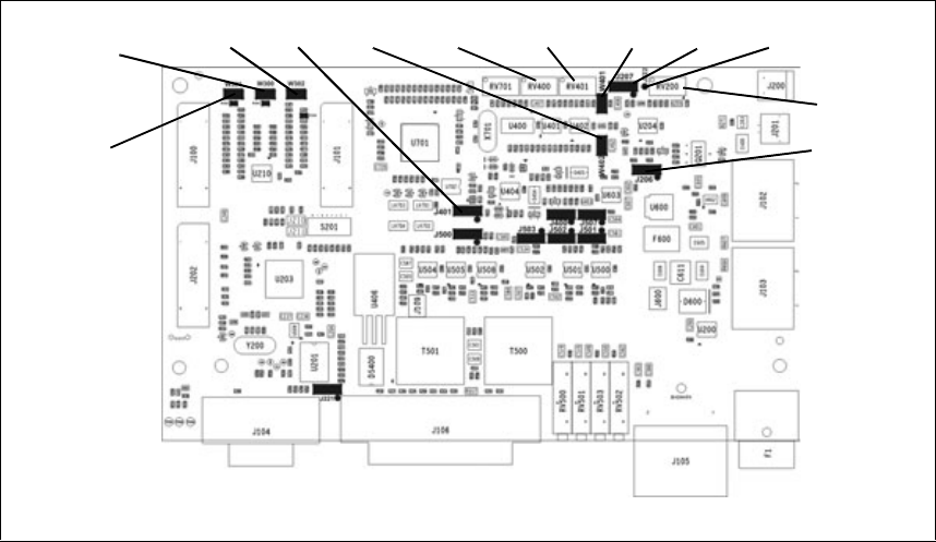
TB7100 Installation and Operation Manual Preparation for Operation 115
© Tait Electronics Limited December 2005
7.9 Additional Settings
The additional link settings control the following functions:
■subaudible signalling
■CTCSS (continuous tone controlled squelch system)
■DCS (digital coded squelch)
■soft off (tx tail time)
■tone on idle
■fan operation
■channel ID
■relay polarity
■channel increment and decrement by function buttons
■CWID (carrier wave identification).
7.10 Adding Subaudible Signalling
The base station is able to decode one CTCSS or DCS tone per channel. It
can also generate one CTCSS or DCS tone per channel. The generated tone
can be the same as the received tone or can be a different tone.
7.10.1 Enabling Subaudible Signalling
Transmitter Module 1. Read the data file out of the transmitter module.
Figure 7.11 System interface link positions
J206
RV200
J207W401RV401W402J401W302
W300
W301
RV400 J222

116 Preparation for Operation TB7100 Installation and Operation Manual
© Tait Electronics Limited December 2005
2. Open the channels form and select the required tone in the Tx Sig
column.
3. Open the Networks > Basic Settings > Subaudible Signalling tab and
configure the subaudible signalling settings (the defaults are suitable
for most applications).
4. Program the new settings into the transmitter.
Receiver Module 1. Read the data file out of the receiver module.
2. Open the channels table and select the required tone in the Rx Sig
column.
3. Open the Networks > Basic Settings > Subaudible Signalling tab and
configure the subaudible signalling settings (the defaults are suitable
for most applications).
4. The Rx tap out point in the receiver (Programmable I/O audio tab)
must be changed to R5. This means that a incoming tone/code is
filtered out by the receiver.
5. Program the new settings into the receiver.
7.10.2 Testing Subaudible Signalling
Before carrying out these tests, the base station must be configured as a line-
controlled base. It must also be connected to the test equipment as described
in “Test Equipment Setup” on page 79.
Tx Subaudible
Signalling Deviation 1. Set up the test set to measure the modulation level and frequency.
2. Ensure the test set audio output is turned off, or disconnect the CTU
audio input from the test set.
3. Activate the Tx Key switch on the CTU.
4. Verify that the measured frequency and deviation of the CTCSS
match the programmed settings.
Note If the measured value does not agree with the programmed set-
tings, the transmitter module is either faulty or needs recalibrating.
Rx Subaudible
Signalling Decode 1. Connect the balanced audio output from the CTU to the audio input
port on the test set.
2. Set up the test set to measure the audio level and distortion.
3. Set the RF signal generator to the correct RF frequency, modulated
with a 1kHz audio tone at 60% of full system deviation.

TB7100 Installation and Operation Manual Preparation for Operation 117
© Tait Electronics Limited December 2005
4. Set the RF output level to -70dBm.
5. Verify that the busy LED on the front panel of the base station turns
on but the Rx gate LED on the CTU does not turn on, and no audio
output is detected from the balanced line output.
6. Modulate the carrier with the required subaudible signalling.
7. Verify that the Rx gate LED on the CTU turns on, and that the 1kHz
audio tone is detected by the test set, and that the measured distortion
level is within the receiver specifications.
8. Turn off the subaudible signal and check that the audio output mutes
again.
Note If high distortion is measured, it is likely that the subaudible signal
is not being filtered out. Verify that the receiver is programmed
with the correct audio tap out point.
7.10.3 Multiple Subaudible Tones
The base station cannot decode multiple subaudible tones on a single
channel. This can be overcome by two methods:
Method 1 1. Third-party equipment is available that can be connected to the base
station to perform the decoding and regeneration of multiple tones.
2. The base station repeater can be configured to simply pass through
any subaudible tone.
Method 2 1. The receiver must not be programmed with any subaudible tones in
the channel table.
2. The Rx tap out point in the receiver (Programmable I/O audio tab)
must be left as the default value of R4. This means that a incoming
tone/code is not filtered out by the receiver.
3. The transmitter must be programmed not to generate any subaudible
tones.
4. The Tx Tap In point in the transmitter (Programmable I/O audio
tab) must be left as the default value of T8. This means that a
incoming tone/code is not filtered out by the transmitter and will be
re-transmitted.
Potential Problems 1. The Rx gate may close before end of reverse tone burst (RTB).
This means the re-transmitted RTB may be shorter than incoming
RTB. A Tx tail (soft off) should be added to overcome this.
2. There is no security for repeaters, as any on-frequency transmission
will be repeated, even if it has no subaudible tone.

118 Preparation for Operation TB7100 Installation and Operation Manual
© Tait Electronics Limited December 2005
7.11 Soft Off (Tx Tail Time)
If subaudible signalling is used, a Tx tail time can be added using the
Networks > Basic Settings > Subaudible Signalling tab. A lead out delay can
be entered in the appropriate field.
7.11.1 Link Settings
Remove the cover as detailed in “Removing the Base Station and Opening
the Tray” on page 54 and set the jumper positions on the system interface
to match the table below. Replace the cover as detailed in “Final
Reassembly” on page 63. Refer to Figure 7.11 on page 115 for the link
location.
Note When link W302 is fitted, resistor R300 must be fitted.
However, if subaudible signalling is not used, adding a lead out delay will
have no effect. If soft off operation is still required, a Tx tail time can be
created by:
1. Linking AUX_GPIO6 and AUX_GPIO7 of the transmitter with link
W302 on the system interface as above.
2. Adding the following to the default Tx configuration:
■AUX_GPIO6 >Direction = input
■AUX_GPIO6 >Action = External PTT 2
■AUX_GPIO6 >Active = High
■AUX_GPIO6 >Debounce = 200 (or smaller if desired)
■External PTT (2) > Transmission Type = None.
Note A maximum of 200 ms tail time can be achieved using this
method.
7.12 Tone On Idle (TOI)
The tone on idle provides a tone that can be used for indicating when the
base station is not transmitting or receiving. The links to enable or disable
the tone on idle are shown in the table below. Both links must be in for the
TOI to work.
Table 7.9 Soft off—link settings
LINK Name Pins Position Function Comments
W302 TX_Key to
TX_GPIO6 link 2 Fitted
Not fitted When fitted this allows two
external PTT to control the
transmitter; used for soft
off mode
Default is fitted

TB7100 Installation and Operation Manual Preparation for Operation 119
© Tait Electronics Limited December 2005
7.12.1 Link Settings
Remove the cover as detailed in “Removing the Base Station and Opening
the Tray” on page 54 and set the jumper positions on the system interface
to match the table below. Replace the cover as detailed in “Final
Reassembly” on page 63. Refer to Figure 7.11 on page 115 for the link
location.
The potentiometers for the tone on idle adjustments shown in the table
below can be found on the system interface module. Refer to Figure 7.11
on page 115 for the potentiometer location.
Table 7.10 Ton on idle (TOI)—link settings
LINK Name Pins Position Function Comments
W401 TOI 9V Enable 2 Fitted
Not fitted Tone on Idle enable
Tone on Idle disable Default is fitted
W402 TOI 4.5V Enable 2 Fitted
Not fitted
Tone on Idle oscillator
enable
Tone on Idle oscillator
disable
Default is fitted
Potentiometer Function
RV400 Frequency adjust
RV401 level adjust
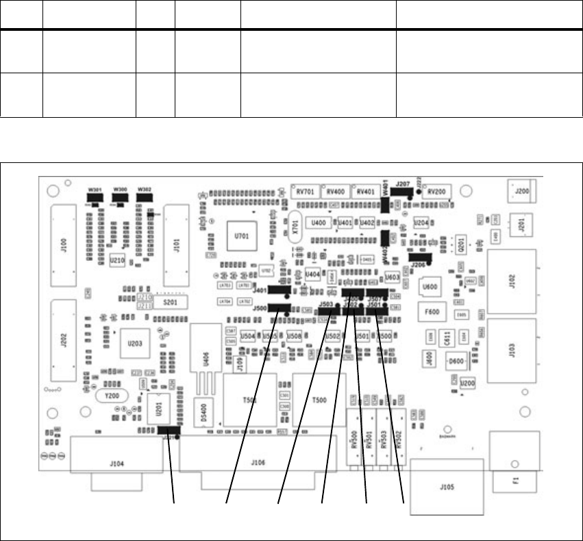
120 Preparation for Operation TB7100 Installation and Operation Manual
© Tait Electronics Limited December 2005
7.13 Fan Operation
The fans can be made to operate in three modes:
■continuous
■on when base station transmits
■on at a set temperature.
The fan operation can be set as shown in the table below.
7.13.1 Link Settings
Remove the cover as detailed in “Removing the Base Station and Opening
the Tray” on page 54 and set the jumper positions on the system interface
to match the table below. Replace the cover as detailed in “Final
Reassembly” on page 63. Refer to Figure 7.11 on page 115 for the link
location.
Table 7.11 Fan operation—link settings
LINK Name Pins Position Function Comments
J206 Fan Control 1 3 1-2
2-3 Fan controlled by J207
Fan always on Default position is 1-2
J207 Fan Control 2 3 1-2
2-3 Fan Tx key-controlled
Fan temperature-controlled Default position is 2-3
Figure 7.12 System interface link positions
J400J500 J502J503 J501J221
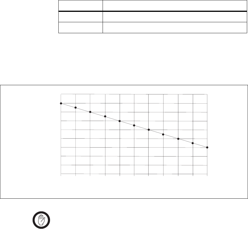
TB7100 Installation and Operation Manual Preparation for Operation 121
© Tait Electronics Limited December 2005
The temperature threshold is set at the factory to 40°C. The potentiometer
and test point to adjust the temperature threshold can be found on the
system interface module. Refer to Figure 7.11 on page 115 for the location.
When adjusting the temperature threshold the fans must be off.
The temperature threshold to voltage relationship is shown in Figure 7.13
on page 121.
Important When using THSD and the user interface PTT, the fan set-
ting should be temperature controlled or always on. This is
because the user interface PTT line does not toggle the
TX-key line on the system interface and the THSD is only
on for short burst of time never allowing the fan time to
spin up.
Designator Function
RV200 temperature threshold adjust
J222 test point for temperature threshold
Figure 7.13 temperature threshold to voltage relationship
0.92 0.98 1.04 1.10 1.16 1.22 1.28 1.34 1.40 1.46 1.52
0
10
20
30
40
50
60
70
80
90
Voltage
Temperature
50
68
86
104
122
140
158
176
194
32
Fahrenheit
Celsius

122 Preparation for Operation TB7100 Installation and Operation Manual
© Tait Electronics Limited December 2005
7.14 Channel ID
Channel ID can be enabled using the links as below.
7.14.1 Link Settings
Remove the cover as detailed in “Removing the Base Station and Opening
the Tray” on page 54 and set the jumper positions on the system interface
to match the table below. Replace the cover as detailed in “Final
Reassembly” on page 63. Refer to Figure 7.11 on page 115 for the link
location.
Note When link W300 is fitted, resistor R304 must be fitted.
When link W301 is fitted, resistor R302 must be fitted.
When Tx/Rx digital input 1-4 are used for channel selection only 16 binary
or 10 BCD channels are available.
When Tx/Rx digital input 1-4 and another line, made from the shorting of
Tx digital in/out 1 and Rx digital in/out 1 on the system interface
connecter are used then a total of 32 binary or 20 BCD channels are
selectable. Requires link W300 to be fitted.
Table 7.12 Channel ID—link settings
LINK Name Pins Position Function Comments
W300 2 Fitted
Not fitted When fitted this allows
both transmit and receive
modules to be controlled by
the same external digital IO
lines, used for BCD; used
with W301
Default is fitted
W301 2 Fitted
Not fitted When fitted this allows
both transmit and receive
modules to be controlled by
the same external digital IO
lines; used with W300
Default is fitted

TB7100 Installation and Operation Manual Preparation for Operation 123
© Tait Electronics Limited December 2005
7.15 Relay Polarity
Relay operation can be configured to be energised when the receiver gate
is active or inactive.
7.15.1 Link Settings
Remove the cover as detailed in “Removing the Base Station and Opening
the Tray” on page 54 and set the jumper positions on the system interface
to match the table below. Replace the cover as detailed in “Final
Reassembly” on page 63. Refer to Figure 7.11 on page 115 for the link
location.
7.16 Channel Increment and Decrement by Function
Keys
Function button one and two can be configured to increment and
decrement the channels. This requires two links fitted to the rear of the user
interface board, this will hard wire the F1 and F2 buttons to the
increment/decrement function. It is recommended F1 & F2 have no other
programmed action.
This option will allow all 99 channels to be selected from the function
buttons.
For more information, refer to the technical note TN-1032-AN
“Implementing Channel Increment and Decrement on the TB7100”
available from http://support.taitworld.com.
Table 7.13 Relay polarity—link settings
LINK Name Pins Position Function Comments
W401 Relay Polarity
Control 31-2
2-3
Energised for receiver active
gate
Energised for receiver
inactive gate
Default is 1-2
124 Preparation for Operation TB7100 Installation and Operation Manual
© Tait Electronics Limited December 2005
7.17 Carrier Wave Identification (CWID)
CWID is a morse identification feature that can be setup using the TB7100
programming application.
7.17.1 Station ID
Can contain a preprogrammed station ID of up to 16 characters in length.
The user may wish to prefix the letters DE before the message, meaning
“from”.
7.17.2 Station ID 2/Message
Can contain a second preprogrammed station ID or a message of up to 130
characters.
7.17.3 Tone Frequency
The Morse tone frequency is programmable from 1Hz to 3000Hz in one
cycle increments. FCC rules state that the frequency shall be 800Hz to
1200Hz.
7.17.4 ID Repeat Time
A programmable repeat time from 1 to 99 minutes. This allows the user to
program how often the ID or message is sent. Setting the output control to
“After PTT” will cause the ID message to be sent following the last
activation of the COR/COS/CTCSS, Inhibit or PTT inputs, provided the
time is met that is programmed in this register.
7.17.5 Speed (Words per Minute)
The speed is programmable from 1 to 99 words per minute (WPM).
7.17.6 Wait Period after Loss of COR/COS/CTCSS Input Before IDing
This register allows from 1 to 99 seconds of delay before the Morse ID will
transmit after COR/COS/CTCSS loss assuming the repeat interval in ID
Repeat Time has expired.
7.17.7 Transmit Key-Up Delay
Programmable key-up delay from 0.0 to 9.9 seconds. This allows for a front
porch delay time before the ID or message is sent. This gives receiving units
TB7100 Installation and Operation Manual Preparation for Operation 125
© Tait Electronics Limited December 2005
with CTCSS decoders time to un-squelch before any Morse code is
transmitted.
7.17.8 Transmit Time Out Time
If programmed to 0 this function is off. Programming from 1 to 999 seconds
will set the repeater to drop out after the number of seconds programmed
in this register. The time out timer is designed to limit conversation length.
7.17.9 Transmit PTT Drop Out Time
This register programs how many seconds the repeater’s transmitter will stay
keyed after loss of COR/COS/CTCSS input. Normally this is programmed
for 2 to 7 seconds. After PTT In is detected, the ID-1 will turn on its PTT
out, as long as the PTT In remains active. After loss of the PTT In, the PTT
out will remain active for the programmed period of time before dropping,
thus allowing another unit to answer before the repeater drops. The ID-1
must be installed in series with the PTT line (i.e. ID-1 installed at break in
station PTT line) for this function to operate.
7.17.10 Output Control
Setting the output Control to “After PTT” will cause the ID message to be
sent following the last activation of the COR/COS/CTCSS, inhibit or
PTT inputs, provided the time is met that is programmed in the register ID
repeat time. setting the output control to “continuous” will cause the ID or
message to be sent at the expiration of a period equal to the delay time. For
example, if register ID repeat time is programmed as 10, the ID or message
will be sent every 10 minutes. This will occur during a conversation if one
is in progress when the timer goes off.
126 Preparation for Operation TB7100 Installation and Operation Manual
© Tait Electronics Limited December 2005

TB7100 Installation and Operation Manual Maintenance Guide 127
© Tait Electronics Limited December 2005
8 Maintenance Guide
The base station is designed to be very reliable and should require little
maintenance. However, performing regular checks will prolong the life of
the equipment and prevent problems from happening.
It is beyond the scope of this manual to list every check that you should
perform on your base station. The type and frequency of maintenance
checks will depend on the location and type of your system. The checks and
procedures listed below can be used as a starting point for your maintenance
schedule.
Performance Checks We suggest you monitor the following operational parameters:
■VSWR
■DC input voltage, especially on transmit
■receiver sensitivity
■the setting of the receiver gate opening
■transmit deviation
These basic checks will provide an overview of how well your base station
is operating.
Receiver There are no special maintenance requirements for the receiver.
Transmitter There are no special maintenance requirements for the transmitter.
System Interface There are no special maintenance requirements for the System interface.
Ventilation The base station has been designed to have a front-to-back cooling airflow.
We strongly recommend that you periodically check and maintain the
ventilation requirements described in “Ventilation” on page 46 to ensure a
long life and trouble-free operation for your base station.
Cooling Fans The cooling fans have a long service life and have no special maintenance
requirements.
Battery If you are using battery, you should check the batteries regularly in
accordance with the manufacturer’s recommendations.
128 Maintenance Guide TB7100 Installation and Operation Manual
© Tait Electronics Limited December 2005

TB7100 Installation and Operation Manual Glossary 129
© Tait Electronics Limited December 2005
Glossary
This glossary contains an alphabetical list of terms and abbreviations related
to the TB7100 base station. For information about trunking, mobile, or
portable terms, consult the glossary provided with the relevant
documentation.
A
accessory An accessory is an ancillary device fitted externally to a base station, such as
an external microphone.
active Digital outputs are active when the base station pulls their voltage low and
current is flowing. Digital inputs are active when external equipment is
pulling them to ground. All base station digital outputs are open collector.
ADC Analog-to-Digital Converter. A device for converting an analog signal to a
digital signal that represents the same information.
air intake
temperature The temperature of the air as measured at the transmitter’s air intake.
anti-kerchunking Anti-kerchunking is a base station feature that discourages users from
“pinging” (kerchunking) the repeater with short bursts of RF.
audible indicators The radio’s audible indicators are used in combination with visual indicators
to provide feedback to the radio user. Types of audible indicators are
incoming call tones, warning tones, confirmation tones, keypress
confidence tones and signalling sidetones.
B
backlighting The radio’s display or keypad lights up when there is activity on the radio,
such as when a key is pressed or when a call is received. The value of the
backlighting timer and how backlighting was activated determine how long
backlighting remains on.
backlighting timer The backlighting timer determines how long backlighting remains on once
it is activated.
130 Glossary TB7100 Installation and Operation Manual
© Tait Electronics Limited December 2005
balanced line A balanced line has two wires carrying equal and opposite signals. It is
typically used in a line-connected base station for connecting to the
despatcher console. The system interface identifies the balanced line out as
Rx line output + and Rx line output -, and the balanced line in as Tx line
input + and Tx line input -.
base station A base station is a tray containing transmitter, receiver and system interface
modules.
BCD BCD (binary coded decimal) is a code in which a string of four binary digits
represents a decimal number.
birdie A birdie is a desensitised channel caused by internal interference. A birdie
can be eliminated by activating a birdie killer on the channel.
birdie killer A birdie killer is an internal circuitry switch that greatly reduces the effect
of a birdie on a channel.
brownout A dip in the supply voltage sufficient to put the control section into
hardware reset.
C
Calibration
Application The Calibration Application is a utility for calibrating various parts of the
receiver and transmitter circuitry.
CCDI2 CCDI2 (computer controlled data interface version 2) is a proprietary Tait
command protocol used between computer equipment and a Tait radio.
The TB7100 base station does not support CCDI2.
CCI CCI (computer controlled interface) is a proprietary Tait command protocol
used between computer equipment and a Tait radio.
channel A channel is a frequency pair (or just a single frequency in a simplex system).
Note: Different channels may have identical frequencies, while other
operating parameters may be different.
channel profile A channel profile is a named set of configuration items relating to the base
station’s RF configuration, transmitter power output and power saving
modes. Like the signalling profile, it can be applied to any channel. Together,
these profiles define most configuration items.
channel spacing Channel spacing is the frequency difference between adjacent channels.
channel table The channel table is the base station’s database of channel configurations.
TB7100 Installation and Operation Manual Glossary 131
© Tait Electronics Limited December 2005
city squelch When a radio’s noise mute threshold is programmed for city squelch, the
radio is less sensitive to interference than if programmed for country squelch
and so stronger signals are required for the radio’s speaker to unmute.
City squelch is also known as local squelch.
CODEC An IC which combines analog-to-digital conversion (coding) and digital-
to-analog conversion (decoding).
configuration file A configuration file consists of all the configuration settings needed for a
base station, stored as a file in the configurations folder. Configuration files
have the extension *.t7p. The TB7100 uses two files, one for the receiver
and one for the transmitter.
country squelch When a radio’s squelch threshold is programmed for country squelch, the
radio is more sensitive than if programmed for city squelch and so the radio’s
speaker unmutes more readily. When programmed for country squelch, the
radio can be used in areas where the signal may be weak and where
maximum range is desirable.
Country squelch is also known as distant squelch.
CTCSS CTCSS (continuous tone controlled squelch system), also known as PL
(private line), is a type of signalling that uses subaudible tones to segregate
groups of users.
CTCSS/DCS filter The CTCSS/DCS filter removes any CTCSS or DCS tones that may be
present on the received audio. The filter limits the range of frequencies the
radio passes from the incoming signal to the speaker and so in some
situations affects signal quality. Filtering can be automatically switched off
for channels that do not have CTCSS or DCS.
CTU A Calibration Test Unit (CTU) is a device used to assist in making testing
and calibration of the TB7100 easier.
CWID CWID (Continuous Wave IDentification) is a method of automatically
identifying the base station using a Morse code.
D
DAC Digital-to-Analog Converter. A device for converting a digital signal to an
analog signal that represents the same information.
data call A data call is a call or part of a call between two radio units that carries data
rather than speech communications. A data call can be a status message,
short data message or non-prescribed data (NPD) call.
DCS DCS (digital coded squelch), also known as DPL (digital private line), is a
type of subaudible signalling used for segregating groups of users. DCS
codes are identified by a three-digit octal number, which forms part of the
132 Glossary TB7100 Installation and Operation Manual
© Tait Electronics Limited December 2005
continuously repeating code word. When assigning DCS signalling for a
channel, you specify the three-digit code.
de-emphasis De-emphasis is a filtering process in the receiver that attenuates higher
frequency audio. It restores pre-emphasised audio to its original relative
proportions.
digital signal
processor The device in a radio that analyses and processes signals in the digital
domain. Also known as DSP.
Duplexer A duplexer is a device for connecting one antenna to a transmitter and
receiver at the same time.
duty cycle Duty cycle is used in relation to the transmitter. It is the proportion of time
(expressed as a percentage) during which the transmitter is keyed.
The transmitter can be operated continuously.
E
economy cycling Economy cycling is the switching between states that occurs when economy
mode is active and after there is no valid activity on a channel for a
preprogrammed time (the economy mode timer). Economy cycling consists
of two states, the receive state and the standby state. The amount of time the
radio spends in each state is determined by the economy duty cycle.
economy duty cycle The economy duty cycle is the amount of time the radio spends in the
receive and standby states during economy cycling.
economy mode Economy mode reduces the radio’s power consumption when it is idle.
When economy mode is active, and there has been no valid activity on a
channel for the duration of the economy mode timer, the radio begins
economy cycling.
economy mode
timer The economy mode timer sets the time between when valid activity was last
detected on a channel and the start of economy cycling.
EIA Electronic Industries Alliance. Accredited by the American National
Standards Institute (ANSI) and responsible for developing
telecommunications and electronics standards in the USA.
EMC Electromagnetic Compatibility. The ability of equipment to operate in its
electromagnetic environment without creating interference with other
devices or being susceptible to disturbance in the presence of other
equipment.
ETSI European Telecommunications Standards Institute. The non-profit
organisation responsible for producing European telecommunications
standards.
TB7100 Installation and Operation Manual Glossary 133
© Tait Electronics Limited December 2005
F
FFSK FFSK (fast frequency shift keying). In Trunking applications this is the
method by which code words are sent over the control channel. In 1200
baud FFSK, a 1200 Hz tone represents a zero and an 1800 Hz tone
represents a one.
frequency band The range of frequencies that the equipment is capable of operating on.
front panel The part of the chassis that has the user interface on it.
Full Duplex Full duplex is the action of receiving and transmitting at the same time.
function key A function key is a key on a radio or radio accessory that can have functions
assigned to it.
G
gating Gating is the process of opening and closing the receiver audio path. When
a valid signal is received, the receiver audio path opens.
GPIO General Purpose Input Output (GPIO) lines are used on the TB7100 to
configure it for different modes.
H
hysteresis Hysteresis is the difference between the upper and lower trigger points. For
example, the receiver gate opens when the upper trigger point is reached,
but will not close until the level falls to the lower trigger point. An adequate
hysteresis prevents the receiver gate from repeatedly opening and closing
when the level is about that of the trigger point.
I
inactive Digital outputs are inactive if the base station is doing nothing to them. They
are floating, open collector outputs. Digital inputs are inactive when they are
open circuit.
indicator Indicators provide feedback to the radio user on how the current operation
is proceeding and on the operating state of the radio. For example, keypress
confidence tones are the tones heard when a keypad key or a function key
is pressed and tell the user that an action is permitted. Tait radios use
combinations of audible indicators and visual indicators.
inhibit Prevents the radio state changing.
134 Glossary TB7100 Installation and Operation Manual
© Tait Electronics Limited December 2005
isolator An isolator is a passive two-port device which transmits power in one
direction, and absorbs power in the other direction. It is used in a PA to
prevent damage to the RF circuitry from high reverse power, and reduces
the generation of spurious product due to the ingress of signals from other
transmitters.
K
kerchunking Kerchunking is transmitting for a second or less without saying anything in
order to test the base station. This results in a ‘kerchunk’ sound.
keypress confidence
tone A keypress confidence tone is a type of audible indicators given each time
the user presses a key to confirm that the action selected is valid.
L
LCD A Liquid Crystal Display (LCD) is used on the TB7100 user interface to
display channel number.
line-controlled base
station A TB7100 is a line-controlled base station when it receives audio (sending
it out via its systems interface), transmits audio received over its systems
interface, and its transmitter is keyed via the Tx Key line.
local squelch See city squelch.
M
Mandatory Settings The mandatory settings are settings in the programming application that
must not be changed from their default states or the TB7100 will not
operate correctly. The Mandatory Settings in the receiver module are not
the same as those in the transmitter module.
mute A mute controls the circumstances under which a received signal is passed
to the radio’s audio output. When a mute is active, the radio’s speaker audio
path opens under certain conditions, determined by the type of signalling
operating on a channel and the noise mute threshold.
N
noise mute The noise mute feature ensures that the radio’s speaker only unmutes when
an intelligible signal is received. A signal is considered intelligible when it is
strong enough to exceed a predetermined noise mute threshold.
noise mute
threshold The noise mute threshold is the level the signal must reach before it is
regarded as intelligible and the radio’s mute is opened.
TB7100 Installation and Operation Manual Glossary 135
© Tait Electronics Limited December 2005
0
operating range Operating range is another term for switching range.
P
PA The PA (power amplifier) is a part of the transmitter that boosts the exciter
output to a certain level sufficient to transmit via the antenna.
power down Radio is switched off.
power up Radio is switched on.
pre-emphasis Pre-emphasis is a process in the transmitter that boosts higher audio
frequencies.
programming manipulating calibration database, radio database.
Programming
Application The programming application is used to create configuration files for the
base station. The programming application can read files from the base
station or load new files onto the base station.
programming
database The programming database is the information that is altered using the radio
programming application. For trunked radios, each programming database
consists of separate network, fleet and radio information.
programming mode The mode of operation of the radio in which computer equipment can read
from and write to the radio database.
Q
quiet operation When quiet operation is active, all audible indicators except incoming call
alerts, sidetones and warning tones are disabled. Contrast with silent
operation.
quiet state The quiet state is the state the radio is in when monitor is inactive the radio
user does not have to listen to traffic that is not intended for them.
R
Recommended
Settings Recommended settings are settings in the programming application that
should not be changed from the recommended default value, but unlike
mandatory settings, the user is permitted to make changes; providing they
verify the correct operation of the enabled or modified feature. No
guarantee is given that a feature will work if the recommended settings
disable the feature or if a recommended value is changed.
136 Glossary TB7100 Installation and Operation Manual
© Tait Electronics Limited December 2005
repeater A repeater receives a radio signal and re-transmits it. Use of a repeater
increases the coverage area of a two-way radio system and ensures more
reliable performance in areas where signals are reflected or attenuated by
buildings or terrain.
In a repeater-based system, the radio’s transmit frequency is the frequency
the repeater is listening on, and the radio’s receive frequency is the frequency
the repeater re-broadcasts signals on.
receive (Rx)
frequency The receive frequency is the frequency that a radio is currently tuned to.
reverse tone burst Reverse tone bursts (RTB) can be used with CTCSS. When reverse tone
bursts are enabled, the phase of the generated tones is reversed for a number
of cycles just before transmission ceases. If the receiver is configured for
reverse tone burst, it responds by closing its gate faster than if the RTB were
not transmitted.
RF RF stands for radio frequency and refers to the part of the electromagnetic
spectrum used to transmit radio and television signals.
RSSI RSSI (Received Signal Strength Indicator) feature that indicates the strength
of the received signal.
Rx Rx is an abbreviation for receive or receiver.
S
sensitivity The sensitivity of a radio receiver is the minimum input signal strength
required to provide a useable output.
SINAD SINAD (Signal plus Noise and Distortion) is a measure of signal quality. It
is the ratio of (signal + noise + distortion) to (noise + distortion). A SINAD
of 12dB corresponds to a signal to noise voltage ratio of 4:1.
subaudible
signalling Subaudible signalling is signalling that is at the bottom end of the range of
audible frequencies. The base station supports CTCSS and DCS subaudible
signalling.
subtone A subtone (subaudible signalling tone) is a CTCSS tone or a DCS code.
switching range The switching range is the range of frequencies that the equipment is tuned
to operate on.
system interface The system interface is the set of inputs to and outputs from the base station
(excluding RF), provided by a module inside the tray.
TB7100 Installation and Operation Manual Glossary 137
© Tait Electronics Limited December 2005
T
TB7100 Base Station A TB7100 base station consists of the equipment necessary to receive and
transmit on one channel. Generally, this means receiver, transmitter and
system interface modules. Often abbreviated to TB7100 or base station.
TCXO Temperature compensated crystal oscillator (voltage controlled). The
frequency reference for the RF part of the radio.
Talk Through
Repeater A TB7100 is a talk through repeater when its audio path is configured to
pass the audio it receives on to the transmitter, and its receiver gate signal is
configured to key the transmitter.
THSD Tait High Speed Data (THSD) is a proprietary data protocol. THSD uses a
four level frequency shift keying modulation scheme.
toggle The term toggle is used to describe the switching between two states.
TOI Tone On Idle (TOI) is an audio tone used on the receiver output to indicate
when the base station is idle.
transmit (Tx)
frequency The transmit frequency is the frequency that all outgoing transmissions are
made on.
transmit inhibit The transmit inhibit feature determines under what conditions a
transmission request does not result in the radio transmitting.
transmit lockout The transmit lockout feature prevents the base station from transmitting for
a time once the transmit timer has expired.
Tx Tx is an abbreviation for transmit or transmitter.
138 Glossary TB7100 Installation and Operation Manual
© Tait Electronics Limited December 2005
U
unbalanced line An unbalanced line has one wire earthed. It is typically used for short
connections, for example, between a base station and a repeater on the same
site. The system interface identifies the wires of unbalanced lines with Rx
audio output, Tx audio input, and Ground.
User Defined
Settings The User Defined Settings are settings in the programming application that
are specific to the customers application. These are the only settings that
need to be changed when configuring a TB7100 for operation.
user interface The user interface panel is an area at the front of the base station with
buttons, LEDs and other controls that let you interact with the base station.
V
valid signal A valid signal is a signal that the receiver responds to by opening the receiver
gate. A signal is valid for example when it is stronger than a minimum level
and when it has the specified subtone.
visual indicator The term “visual indicator” refers to a visual cue the radio gives to provide
feedback to the user. Visual indicators are used in combination with audible
indicators. Visual indicators include LEDs and LCD display text.
VSWR Voltage Standing Wave Ratio (VSWR) is the ratio of the maximum peak
voltage anywhere on the line to the minimum value anywhere on the line.
A perfectly matched line has a VSWR of 1:1. A high ratio indicates that the
antenna subsystem is poorly matched.
W
Watchdog A watchdog circuit checks that the system is still responding. If the system
does not respond (because the firmware has locked up), the circuit resets the
system.

TB7100 Installation and Operation Manual 139
© Tait Electronics Limited December 2005
Tait General Software Licence Agreement
This legal document is an Agreement between
you (the “Licensee”) and Tait Electronics
Limited (“Tait”). By using any of the Software
or Firmware items prior-installed in the
related Tait product, included on CD or
downloaded from the Tait website,
(hereinafter referred to as “the Software or
Firmware”) you agree to be bound by the
terms of this Agreement. If you do not agree
to the terms of this Agreement, do not install
and use any of the Software or Firmware.
If you install and use any of the Software or
Firmware that will be deemed to be
acceptance of the terms of this
licence agreement.
The terms of this Agreement shall apply
subject only to any express written terms of
agreement to the contrary between Tait and
the Licensee.
Licence
TAIT GRANTS TO YOU AS LICENSEE THE NON-
EXCLUSIVE RIGHT TO USE THE SOFTWARE OR
FIRMWARE ON A SINGLE MACHINE PROVIDED
YOU MAY ONLY:
1. COPY THE SOFTWARE OR FIRMWARE INTO
ANY MACHINE READABLE OR PRINTED FORM
FOR BACKUP PURPOSES IN SUPPORT OF YOUR
USE OF THE PROGRAM ON THE SINGLE MACHINE
(CERTAIN PROGRAMS, HOWEVER, MAY INCLUDE
MECHANISMS TO LIMIT OR INHIBIT COPYING,
THEY ARE MARKED “COPY PROTECTED”),
PROVIDED THE COPYRIGHT NOTICE MUST BE
REPRODUCED AND INCLUDED ON ANY SUCH
COPY OF THE SOFTWARE OR FIRMWARE;
AND / OR
2. MERGE IT INTO ANOTHER PROGRAM FOR
YOUR USE ON THE SINGLE MACHINE (ANY
PORTION OF ANY SOFTWARE OR FIRMWARE
MERGED INTO ANOTHER PROGRAM WILL
CONTINUE TO BE SUBJECT TO THE TERMS AND
CONDITIONS OF THIS AGREEMENT).
THE LICENSEE MAY NOT DUPLICATE, MODIFY,
REVERSE COMPILE OR REVERSE ASSEMBLE ANY
SOFTWARE OR FIRMWARE IN WHOLE OR PART.
Important Notice
THE SOFTWARE OR FIRMWARE MAY CONTAIN
OPEN SOURCE SOFTWARE COMPONENTS
(“OPEN SOURCE COMPONENTS”). OPEN SOURCE
COMPONENTS ARE EXCLUDED FROM THE TERMS
OF THIS AGREEMENT EXCEPT AS EXPRESSLY
STATED IN THIS AGREEMENT AND ARE COVERED
BY THE TERMS OF THEIR RESPECTIVE LICENCES
WHICH MAY EXCLUDE OR LIMIT ANY
WARRANTY FROM OR LIABILITY OF THE
DEVELOPERS AND/OR COPYRIGHT HOLDERS OF
THE OPEN SOURCE COMPONENT FOR THE
PERFORMANCE OF THOSE OPEN SOURCE
COMPONENTS. YOU AGREE TO BE BOUND BY
THE TERMS AND CONDITIONS OF EACH SUCH
LICENCE. FOR MORE INFORMATION SEE:
http://support.taitworld.com/go/opensource
Title to Software
THIS AGREEMENT DOES NOT CONSTITUTE A
CONTRACT OF SALE IN RELATION TO THE
SOFTWARE OR FIRMWARE SUPPLIED TO THE
LICENSEE. NOT WITHSTANDING THE LICENSEE
MAY OWN THE MAGNETIC OR OTHER PHYSICAL
MEDIA ON WHICH THE SOFTWARE OR
FIRMWARE WAS ORIGINALLY SUPPLIED, OR HAS
SUBSEQUENTLY BEEN RECORDED OR FIXED, IT IS
A FUNDAMENTAL TERM OF THIS AGREEMENT
THAT AT ALL TIMES TITLE AND OWNERSHIP OF
THE SOFTWARE OR FIRMWARE, WHETHER ON
THE ORIGINAL MEDIA OR OTHERWISE, SHALL
REMAIN VESTED IN TAIT OR THIRD PARTIES
WHO HAVE GRANTED LICENCES TO TAIT.
Term and Termination
THIS LICENCE SHALL BE EFFECTIVE UNTIL
TERMINATED IN ACCORDANCE WITH THE
PROVISIONS OF THIS AGREEMENT. THE LICENSEE
MAY TERMINATE THIS LICENCE AT ANY TIME BY
DESTROYING ALL COPIES OF THE SOFTWARE OR
FIRMWARE AND ASSOCIATED WRITTEN
MATERIALS. THIS LICENCE WILL BE TERMINATED
AUTOMATICALLY AND WITHOUT NOTICE FROM
TAIT IN THE EVENT THAT THE LICENSEE FAILS TO
COMPLY WITH ANY TERM OR CONDITION OF
THIS AGREEMENT. THE LICENSEE AGREES TO
DESTROY ALL COPIES OF THE SOFTWARE OR
FIRMWARE AND ASSOCIATED WRITTEN
MATERIALS IN THE EVENT OF
SUCH TERMINATION.
140 TB7100 Installation and Operation Manual
© Tait Electronics Limited December 2005
Limited Warranty
THE SOFTWARE OR FIRMWARE (INCLUDING
OPEN SOURCE COMPONENTS) IS SUPPLIED BY
TAIT AND ACCEPTED BY THE LICENSEE “AS IS”
WITHOUT WARRANTY OF ANY KIND EITHER
EXPRESSED OR IMPLIED, INCLUDING BUT NOT
BEING LIMITED TO ANY IMPLIED WARRANTIES AS
TO MERCHANTABILITY OR FITNESS FOR ANY
PARTICULAR PURPOSE. THE LICENSEE
ACKNOWLEDGES THAT THE SOFTWARE OR
FIRMWARE (INCLUDING OPEN SOURCE
COMPONENTS) IS USED BY IT IN BUSINESS AND
ACCORDINGLY TO THE MAXIMUM EXTENT
PERMITTED BY LAW NO TERMS OR WARRANTIES
WHICH ARE IMPLIED BY LEGISLATION SHALL
APPLY TO THIS AGREEMENT. TAIT DOES NOT
WARRANT THAT THE FUNCTIONS CONTAINED
IN THE SOFTWARE OR FIRMWARE (INCLUDING
OPEN SOURCE COMPONENTS) WILL MEET THE
LICENSEE’S REQUIREMENTS OR THAT THE
OPERATION OF THE SOFTWARE OR FIRMWARE
(INCLUDING OPEN SOURCE COMPONENTS) WILL
BE UNINTERRUPTED OR ERROR FREE.
Exclusion of Liability
IN NO CIRCUMSTANCES SHALL TAIT BE UNDER
ANY LIABILITY TO THE LICENSEE, OR ANY
OTHER PERSON WHATSOEVER, WHETHER IN
TORT (INCLUDING NEGLIGENCE), CONTRACT
(EXCEPT AS EXPRESSLY PROVIDED IN THIS
AGREEMENT), EQUITY, UNDER ANY STATUTE,
OR OTHERWISE AT LAW FOR ANY LOSSES OR
DAMAGES WHETHER GENERAL, SPECIAL,
EXEMPLARY, PUNITIVE, DIRECT, INDIRECT OR
CONSEQUENTIAL ARISING OUT OF OR IN
CONNECTION WITH ANY USE OR INABILITY OF
USING THE SOFTWARE OR FIRMWARE
(INCLUDING OPEN SOURCE COMPONENTS).
THE LICENSEE’S SOLE REMEDY AGAINST TAIT
WILL BE LIMITED TO BREACH OF CONTRACT
AND TAIT’S SOLE AND TOTAL LIABILITY FOR ANY
SUCH CLAIM SHALL BE LIMITED AT THE OPTION
OF TAIT TO THE REPAIR OR REPLACEMENT OF
THE SOFTWARE OR FIRMWARE OR THE REFUND
OF THE PURCHASE PRICE OF THE SOFTWARE
OR FIRMWARE.
General
THE LICENSEE CONFIRMS THAT IT SHALL
COMPLY WITH THE PROVISIONS OF LAW IN
RELATION TO THE SOFTWARE OR FIRMWARE.
Law and Jurisdiction
THIS AGREEMENT SHALL BE SUBJECT TO AND
CONSTRUED IN ACCORDANCE WITH
NEW ZEALAND LAW AND DISPUTES BETWEEN
THE PARTIES CONCERNING THE PROVISIONS
HEREOF SHALL BE DETERMINED BY THE NEW
ZEALAND COURTS OF LAW. PROVIDED HOWEVER
TAIT MAY AT ITS ELECTION BRING PROCEEDINGS
FOR BREACH OF THE TERMS HEREOF OR FOR
THE ENFORCEMENT OF ANY JUDGEMENT IN
RELATION TO A BREACH OF THE TERMS HEREOF
IN ANY JURISDICTION TAIT CONSIDERS FIT FOR
THE PURPOSE OF ENSURING COMPLIANCE WITH
THE TERMS HEREOF OR OBTAINING RELIEF FOR
BREACH OF THE TERMS HEREOF.
No Dealings
THE LICENSEE MAY NOT SUBLICENSE, ASSIGN OR
TRANSFER THE LICENCE OR THE PROGRAM
EXCEPT AS EXPRESSLY PROVIDED IN THIS
AGREEMENT. ANY ATTEMPT OTHERWISE TO
SUBLICENSE, ASSIGN OR TRANSFER ANY OF THE
RIGHTS, DUTIES OR OBLIGATIONS HEREUNDER
IS VOID.
No Other Terms
THE LICENSEE ACKNOWLEDGES THAT IT HAS
READ THIS AGREEMENT, UNDERSTANDS IT AND
AGREES TO BE BOUND BY ITS TERMS AND
CONDITIONS. THE LICENSEE FURTHER AGREES
THAT SUBJECT ONLY TO ANY EXPRESS WRITTEN
TERMS OF AGREEMENT TO THE CONTRARY
BETWEEN TAIT AND THE LICENSEE THIS IS THE
COMPLETE AND EXCLUSIVE STATEMENT OF THE
AGREEMENT BETWEEN IT AND TAIT IN
RELATION TO THE SOFTWARE OR FIRMWARE
WHICH SUPERSEDES ANY PROPOSAL OR PRIOR
AGREEMENT, ORAL OR WRITTEN AND ANY
OTHER COMMUNICATIONS BETWEEN THE
LICENSEE AND TAIT RELATING TO THE
SOFTWARE OR FIRMWARE.

TB7100 Installation and Operation Manual 141
© Tait Electronics Limited December 2005
Directive 1999/5/EC Declaration of Conformity
da Dansk
Undertegnede Tait Electronics Limited erklærer
herved, at følgende udstyr TBBA4A, TBBB1A
& TBBH5A overholder de væsentlige krav og
øvrige relevante krav i direktiv 1999/5/EF.
Se endvidere: http://eudocs.taitworld.com/
de Deutsch
Hiermit erklärt Tait Electronics Limited die
Übereinstimmung des Gerätes TBBA4A,
TBBB1A & TBBH5A mit den grundlegenden
Anforderungen und den anderen relevanten
Festlegungen der Richtlinie 1999/5/EG.
Siehe auch: http://eudocs.taitworld.com/
el Ελληνικός
Με την παρουσα Tait Electronics Limited
δηλωνει οτι TBBA4A, TBBB1A & TBBH5A
συµµορφωνεται προσ τισ ουσιωδεισ
απαιτησεισ και τισ λοιπεσ σχετικεσ διαταξεισ
τησ οδηγιασ 1999/5/ΕΚ.
βλέπε και: http://eudocs.taitworld.com/
en English
Tait Electronics Limited declares that this
TBBA4A, TBBB1A & TBBH5A complies with
the essential requirements and other relevant
provisions of Directive 1999/5/EC.
See also: http://eudocs.taitworld.com/
es Español
Por medio de la presente Tait Electronics
Limited declara que el TBBA4A, el TBBB1A y
el TBBH5A cumplen con los requisitos
esenciales y cualesquiera otras disposiciones
aplicables o exigibles de la Directiva 1999/5/CE.
Vea también: http://eudocs.taitworld.com/
fi Suomi
Tait Electronics Limited vakuuttaa täten että
TBBA4A, TBBB1A & TBBH5A tyyppinen
laite on direktiivin 1999/5/EY oleellisten
vaatimusten ja sitä koskevien direktiivin muiden
ehtojen mukainen.
Katso: http://eudocs.taitworld.com/
fr Français
Par la présente, Tait Electronics Limited déclare
que l'appareil TBBA4A, TBBB1A & TBBH5A
est conforme aux exigences essentielles et aux
autres dispositions pertinentes de la directive
1999/5/CE.
Voir aussi: http://eudocs.taitworld.com/
it Italiano
Con la presente Tait Electronics Limited dichiara
che questo TBBA4A, TBBB1A & TBBH5A è
conforme ai requisiti essenziali ed alle altre
disposizioni pertinenti stabilite dalla direttiva
1999/5/CE.
Vedi anche: http://eudocs.taitworld.com/
nl Nederlands
Hierbij verklaart Tait Electronics Limited dat het
toestel TBBA4A, TBBB1A & TBBH5A in
overeenstemming is met de essentiële eisen en de
andere relevante bepalingen van richtlijn 1999/
5/ EG.
Zie ook: http://eudocs.taitworld.com/
pt Português
Tait Electronics Limited declara que este
TBBA4A, TBBB1A & TBBH5A está conforme
com os requisitos essenciais e outras provisões da
Directiva 1999/5/CE.
Veja também: http://eudocs.taitworld.com/
sv Svensk
Härmed intygar Tait Electronics Limited att
denna TBBA4A, TBBB1A & TBBH5A står I
överensstämmelse med de väsentliga
egenskapskrav och övriga relevanta
bestämmelser som framgår av direktiv 1999/5/
EG.
Se även: http://eudocs.taitworld.com/
142 TB7100 Installation and Operation Manual
© Tait Electronics Limited December 2005