Tait TEL0061 Paging Transmitter User Manual PagingBoardFitInstruction
Tait Limited Paging Transmitter PagingBoardFitInstruction
UserManual.wiki
>
Tait
>
TEL0061 User Manual
>
PagingBoardFitInstruction
Contents
1.
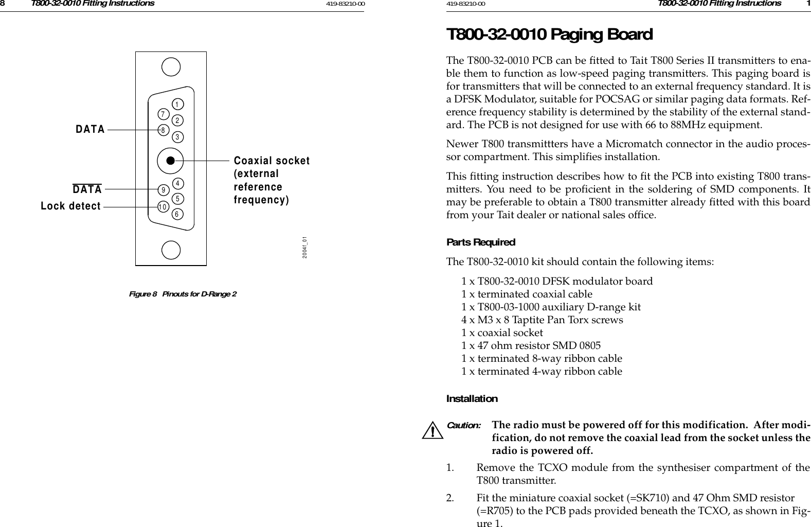
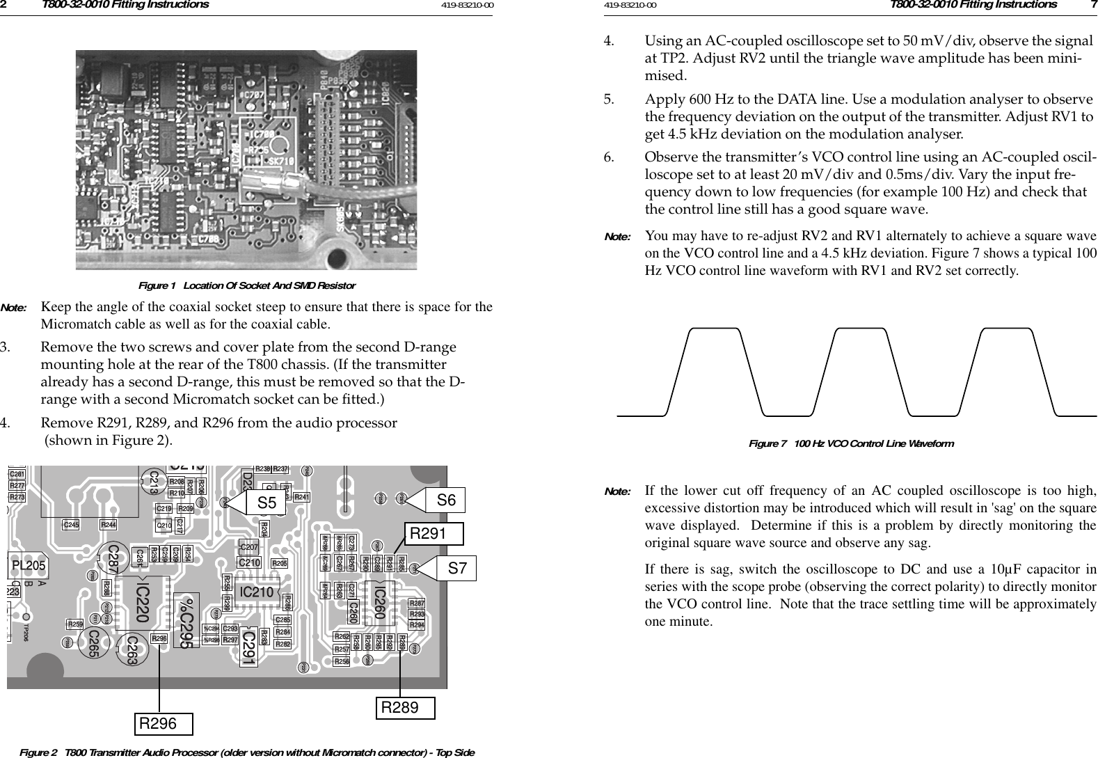
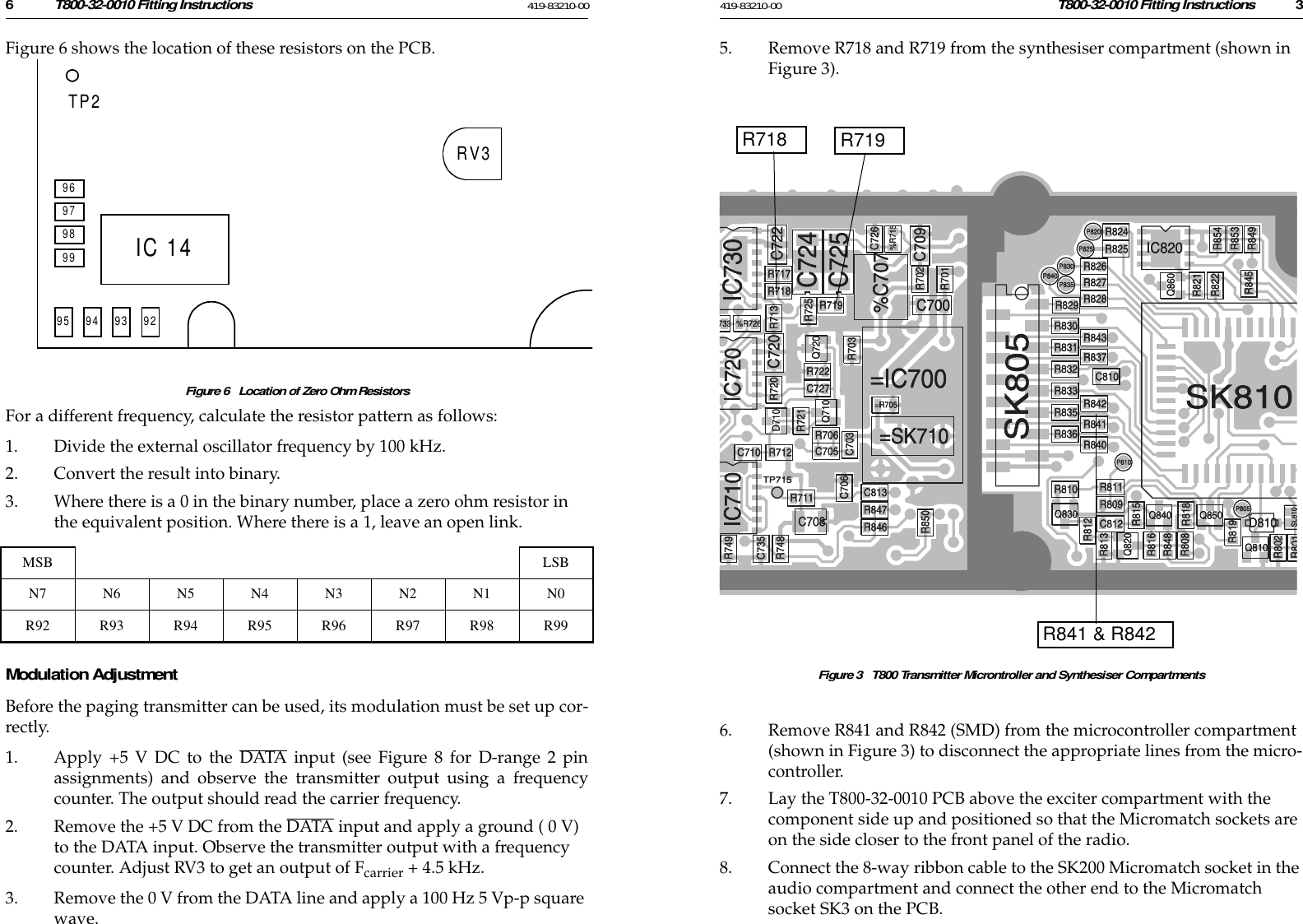
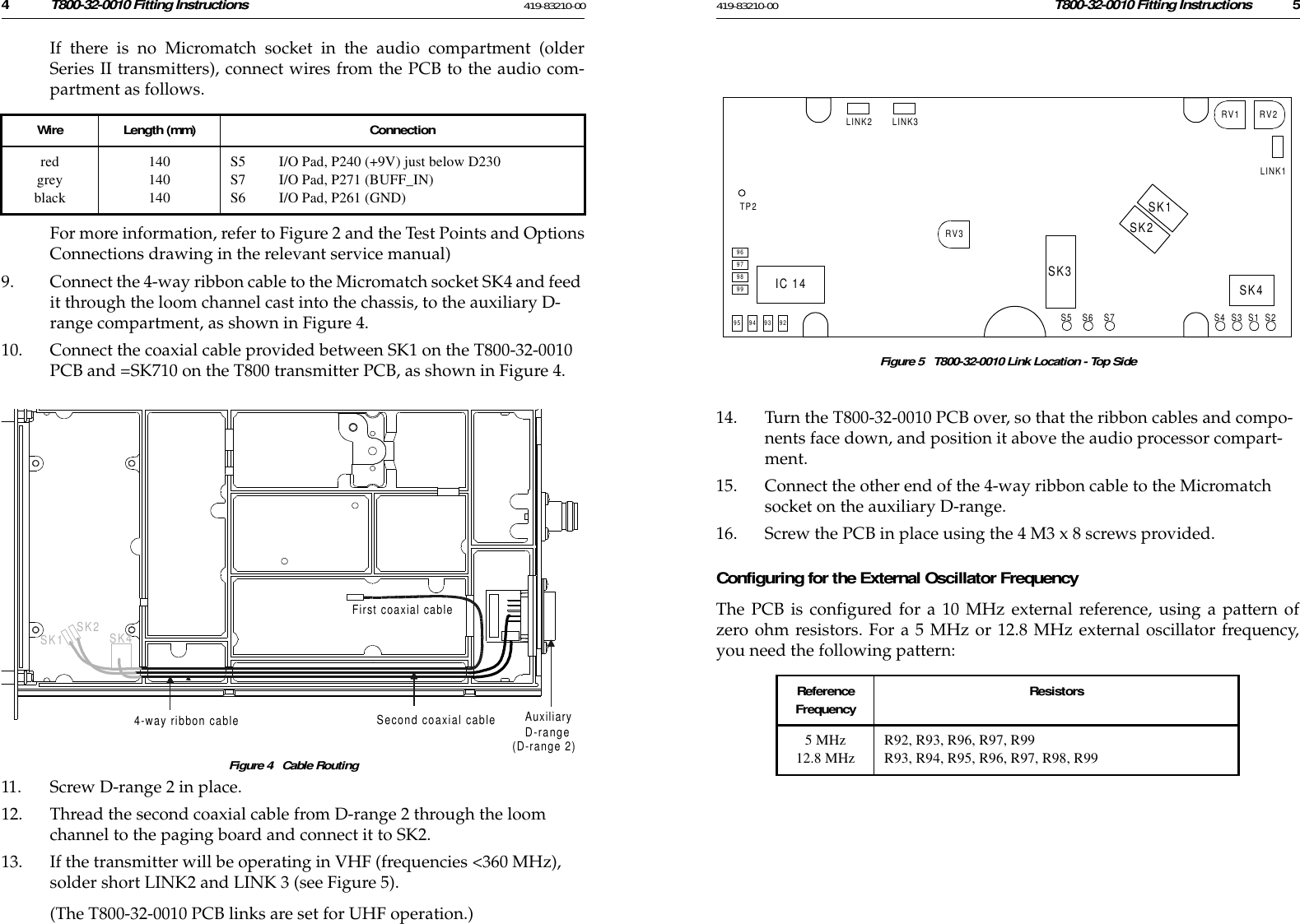
PagingBoardFitInstruction
2.
PagingBoardPCBLayout
3.
Exciter Installation
4.
Exciter Specification
5.
PowerAmpInstall
6.
PowerAmp Specification
PagingBoardFitInstruction
Navigation menu
Upload a User Manual
Namespaces
Wiki Guide
HTML
PDF
Info
Views
User Manual
Discussion / Help
Navigation