Tait TMAC0C Mobile Transceiver User Manual TM8200 user s guide
Tait Limited Mobile Transceiver TM8200 user s guide
Tait >
Exhibit D Users Manual per 2 1033 c3
TAIT:THERIG
HTFIT

3
Directive 1999/5/EC Declaration of Conformity
da Dansk
Undertegnede Tait Electronics Limited erklærer
herved, at følgende udstyr TMAA4C, TMAB1C,
TMAH5C, TMAH6C & TMAC0C overholder de
væsentlige krav og øvrige relevante krav i
direktiv 1999/5/EF.
Se endvidere:
http://eudocs.taitworld.com/
de Deutsch
Hiermit erklärt Tait Electronics Limited die
Übereinstimmung der Geräte TMAA4C,
TMAB1C, TMAH5C, TMAH6C & TMAC0C mit
den grundlegenden Anforderungen und den
anderen relevanten Festlegungen der Richtlinie
1999/5/EG.
Siehe auch:
http://eudocs.taitworld.com/
el Ελληνικός
Με την παρουσα Tait Electronics Limited
δηλωνει οτι TMAA4C, TMAB1C, TMAH5C,
TMAH6C & TMAC0C συμμορφωνεται
προσ τισ ουσιωδεισ απαιτησεισ και τισ
λοιπεσ σχετικεσ διαταξεισ τησ
οδηγιασ 1999/5/ΕΚ.
βλέπε και:
http://eudocs.taitworld.com/
en English
Tait Electronics Limited declares that this
TMAA4C, TMAB1C, TMAH5C, TMAH6C &
TMAC0C complies with the essential require-
ments and other relevant provisions of
Directive 1999/5/EC.
See also:
http://eudocs.taitworld.com/
es Español
Por medio de la presente Tait Electronics Limi-
ted declara que el TMAA4C, TMAB1C,
TMAH5C, TMAH6C & TMAC0C cumple con
los requisitos esenciales y cualesquiera otras
disposiciones aplicables o exigibles de la
Directiva 1999/5/CE. Vease también:
http://eudocs.taitworld.com/
fi Suomi
Tait Electronics Limited vakuuttaa täten että
TMAA4C, TMAB1C, TMAH5C, TMAH6C &
TMAC0C tyyppinen laite on direktiivin
1999/5/EY oleellisten vaatimusten ja sitä
koskevien direktiivin muiden ehtojen mukai-
nen.
Katso:
http://eudocs.taitworld.com/
fr Français
Par la présente, Tait Electronics Limited déclare
que les appareils TMAA4C, TMAB1C,
TMAH5C, TMAH6C & TMAC0C sont confor-
mes aux exigences essentielles et aux autres
dispositions pertinentes de la directive
1999/5/CE.
Voir aussi:
http://eudocs.taitworld.com/
it Italiano
Con la presente Tait Electronics Limited
dichiara che questo TMAA4C, TMAB1C,
TMAH5C, TMAH6C & TMAC0C è conforme ai
requisiti essenziali ed alle altre disposizioni
pertinenti stabilite dalla direttiva 1999/5/CE.
Vedi anche:
http://eudocs.taitworld.com/
nl Nederlands
Hierbij verklaart Tait Electronics Limited dat het
toestel TMAA4C, TMAB1C, TMAH5C,
TMAH6C & TMAC0C in overeenstemming is
met de essentiële eisen en de andere relevante
bepalingen van richtlijn 1999/5/ EG.
Zie ook:
http://eudocs.taitworld.com/
pt Português
Tait Electronics Limited declara que este
TMAA4C, TMAB1C, TMAH5C, TMAH6C &
TMAC0C está conforme com os requisitos
essenciais e outras provisões da Directiva
1999/5/CE.
Veja também:
http://eudocs.taitworld.com/
sv Svensk
Härmed intygar Tait Electronics Limited att
denna TMAA4C, TMAB1C, TMAH5C,
TMAH6C & TMAC0C står I överensstämmelse
med de väsentliga egenskapskrav och övriga
relevanta bestämmelser som framgår av direk-
tiv 1999/5/EG.
Se även:
http://eudocs.taitworld.com/
4
Copyright and trademarks
All information contained in this document is the property of
Tait Electronics Limited. All rights reserved. This document
may not, in whole or in part, be copied, photocopied,
reproduced, translated, stored, or reduced to any electronic
medium or machine-readable form, without prior written
permission from Tait Electronics Limited.
The word TAIT and the TAIT logo are trademarks of Tait
Electronics Limited.
All trade names referenced are the service mark, trademark
or registered trademark of the respective manufacturers.
Disclaimer
There are no warranties extended or granted by this
document. Tait Electronics Limited accepts no responsibility
for damage arising from use of the information contained in
the document or of the equipment and software it describes.
It is the responsibility of the user to ensure that use of such
information, equipment and software complies with the
laws, rules and regulations of the applicable jurisdictions.
Enquiries and comments
If you have any enquiries regarding this document, or any
comments, suggestions and notifications of errors, please
contact Technical Support.
Updates of manual and equipment
In the interests of improving the performance, reliability or
servicing of the equipment, Tait Electronics Limited reserves
the right to update the equipment or this document or both
without prior notice.

5
Intellectual property rights
This product may be protected by one or more patents or
designs of Tait Electronics Limited together with their
international equivalents, pending patent or design
applications, and registered trade marks: NZ409837,
NZ409838, NZ508806, NZ508807, NZ509242, NZ509640,
NZ509959, NZ510496, NZ511155, NZ511421,
NZ516280/NZ519742, NZ520650/NZ537902, NZ521450,
NZ522236, NZ524369, NZ524378, NZ524509, NZ524537,
NZ524630, NZ530819, NZ534475, NZ534692, NZ535471,
NZ537434, NZ546295, NZ547713, NZ569985,
AU2003281447, AU2004216984, AU2005207405,
AU2005267973, AU11677/2008, AU13745/2008,
CA2554213, CA2574670, CN200830113832.x,
CN200830113833.4, EU1,532,866, EU1,599,792,
EU05704655.9, EU000915475-0001,
EU000915475-0002, GB23865476, GB2386010,
GB2413249, GB2413445, US11/232716, US10/597339,
US10/520827, US5,745,840, US7,411,461, US10/546696,
US10/546,697, US10/520827, US10/547964,
US10/523952, US11/572700, US29/306491,
US61/085036.
Environmental responsibilities
Tait Electronics Limited is an environmentally responsible
company which supports waste minimization, material
recovery and restrictions in the use of hazardous materials.
The European Union’s Waste Electrical and Electronic
Equipment (WEEE) Directive requires that this product be
disposed of separately from the general waste stream when
its service life is over. For more information about how to
dispose of your unwanted Tait product, visit the Tait
Electronics WEEE website at www.taitworld.com/weee.

6
Please be environmentally responsible and dispose through
the original supplier, or contact Tait Electronics Limited.
Tait Electronics Limited also complies with the Restriction of
the Use of Certain Hazardous Substances in Electrical and
Electronic Equipment (RoHS) Directive in the European
Union.
In China, we comply with the Measures for Administration of
the Pollution Control of Electronic Information Products. We
will comply with environmental requirements in other
markets as they are introduced.
About this guide
This user’s guide provides information about the TM8250,
TM8254 and TM8255 mobile radios. The radio behaviour
described in this guide applies to radios with firmware
version 6.0x and higher. If you need further assistance or
your radio does not operate as you expect, contact your
radio provider.
Website: For information about how to install your
TM8200 radio, go to www.taitworld.com/technical.

For your safety 7
For your safety
Before using your radio, please read the following important
safety and compliance information.
Safety warnings used in this guide
Within this guide, the following conventions are used to alert
you to important safety information:
Warning: There is a potential risk of death or serious injury.
Caution: There is the risk of minor or moderate injury
to people.
Caution: “Caution” is used without the safety alert symbol
when there is a risk of equipment damage or malfunction.
Radio frequency exposure information
For your own safety and to ensure you comply with the
Federal Communication Commission’s (FCC) radio
frequency (RF) exposure guidelines, please read the following
information before using this radio.
Using this radio
You should use this radio only for work-related purposes (it is
not authorized for any other use) and if you are fully aware
of, and can exercise control over, your exposure to RF energy.
To prevent exceeding FCC RF exposure limits, you must
control the amount and duration of RF that you and other
people are exposed to.

8For your safety
It is also important that you:
■Do not remove the RF exposure label from the radio.
■Ensure this RF exposure information accompanies the
radio when it is transferred to other users.
■Do not use the radio if you do not adhere to the
guidelines on controlling your exposure to RF.
Controlling your exposure to RF energy
This radio emits RF energy or radio waves primarily when
calls are made. RF is a form of electromagnetic energy (as is
sunlight), and there are recommended levels of maximum
RF exposure.
To control your exposure to RF and comply with the
maximum exposure limits for occupational/controlled
environments, follow these guidelines:
■Do not talk (transmit) on the radio more than the rated
transmit duty cycle. This is important because the radio
radiates more energy when it is transmitting than when it
is receiving.
■While you are transmitting (talking or sending data) on
the radio, you must ensure that there is always a distance
of 0.9m (35 inches) between people and the antenna.
This is the minimum safe distance.
■Use the radio only with Tait-approved antennas and
attachments, and make only authorized modifications to
the antenna otherwise you could damage the radio and
violate FCC regulations.
Website: For more information on what RF energy is
and how to control your exposure to it, go to
www.fcc.gov/oet/rfsafety/rf-faqs.html.
For your safety 9
Compliance with RF energy exposure standards
This two-way radio complies with these RF energy exposure
standards and guidelines:
■United States Federal Communications Commission,
Code of Federal Regulations; 47 CFR 1.1307, 1.1310
and 2.1091
■American National Standards Institute (ANSI) / Institute
of Electrical and Electronic Engineers (IEEE) C95. 1-1992
■Institute of Electrical and Electronic Engineers (IEEE)
C95.1-1999 Edition.
This radio complies with the IEEE (FCC) and ICNIRP exposure
limits for occupational/controlled RF exposure environments
at operating duty factors of up to 50% talk to 50% listen.
Radio frequency emissions limits in the USA
Part 15 of the FCC Rules imposes RF emission limits on
electronic equipment to prevent interference to reception of
broadcast services.
This device complies with Part 15 of the FCC Rules.
Operation is subject to the condition that this device does
not cause harmful interference.
Note:
Changes or modifications to this device that are not
expressly approved by Tait Electronics Limited may make its use
illegal.
Unapproved modifications or changes to radio
The radio is designed to satisfy the applicable compliance
regulations. Do not make modifications or changes to the
radio that are not expressly approved by Tait Electronics
Limited. Failure to do so could invalidate compliance
requirements and void the user’s authority to operate
the radio.

10 For your safety
Health, safety and electromagnetic compatibility
in Europe
In the European Union, radio and telecommunications
equipment is regulated by Directive 1999/5/EC, also known
as the Radio and Telecommunications Terminal Equipment
(R&TTE) directive. The requirements of this directive include
protection of health and safety of users, as well as
electromagnetic compatibility.
Intended use
This product is an FM radio transceiver. It is intended for
radiocommunication in the Private Mobile Radio (PMR) or
Public Access Mobile Radio (PAMR) services, to be used in all
member states of the European Union (EU) and states within
the European Economic Area (EEA).
Restrictions
This product can be programmed to transmit on frequencies
that are not harmonised throughout the EU/EEA, and will
require a licence to operate in each member state.
This product can be programmed for frequencies or
emissions that may make its use illegal. Where applicable, a
license must be obtained before this product is used. All
license requirements must be observed. Limitations may
apply to transmitter power, operating frequency, channel
spacing, and emission.
Declaration of conformity
Brief Declarations of Conformity appear on page 3.
Website: To download the formal declaration of
conformity, go to http://eudocs.taitworld.com.
A signed and dated paper copy of the declaration of
conformity can be obtained from Tait Europe Limited.

For your safety 11
Electromagnetic compatibility in European vehicles
In the European Community, radio equipment fitted to
automotive vehicles is regulated by Directive 72/245/EEC, as
amended by 95/54/EC. The requirements of this directive
cover the electromagnetic compatibility of electrical or
electronic equipment fitted to automotive vehicles.
Note:
To meet the requirements of Directive 72/245/EEC (as
amended by 95/54/EC) installation of this product in a vehicle
must be performed according to the instructions provided, and
any guidelines of the vehicle manufacturer.
EN 60950 requirements (25 watt radios)
This radio complies with the European Union standard
EN 60950 when operated up to the rated 33% duty cycle of
two minutes transmit and four minutes receive, and with
ambient temperatures of 30°C or lower.
Caution: Operation outside these limits may cause the
external temperature of the radio to rise higher than this
standard permits.
Interference with electronic devices
Some electronic devices may be prone to malfunction due to
the lack of protection from RF energy that is present when
your radio is transmitting.
Examples of electronic devices that may be affected by RF
energy are:
■vehicular electronic systems such as fuel injection, anti-
skid brakes, and cruise control
■medical devices such as hearing aids and pacemakers
■medical equipment in hospitals or health care facilities.
Consult the manufacturer (or its representative) of the
equipment to determine whether these electronic circuits will
perform normally when the radio is transmitting.
12 For your safety
AS/NZS 4365 requirements
Products designed to operate at a frequency of 476MHz have
been approved for operation in the UHF Citizens Band Radio
Service which is licensed in Australia by the ACMA
Radiocommunications (Citizens Band Radio Stations) Class
Licence and in New Zealand by the MED General User Radio
Licence for Citizens Band Radio. Operation is subject to
conditions contained within those licences.
Repeaters operate by receiving a transmission on one
channel and re-transmitting it on another. Operators are
required to avoid using local repeater input channels, which
will be in the range of 31 to 38, unless it is intended to use
the repeater facility and to avoid using local repeater output
channels, which will be in the range 1 to 8, at any time.
In Australia:
■Except in an emergency, a CB transmitter must not be
operated on UHF channels 5 and 35 and no voice
transmissions are permitted on data channels 22 and 23.
Equipment meeting this standard will inhibit voice
operation on channels 22 and 23.
■Channel 11 is the customary calling channel for
establishing communications.
■Channel 40 is the customary road vehicle channel.
Frequency band reserved for distress beacons
Frequency band 406 to 406.1 MHz is reserved for use by
distress beacons. Transmissions should not be made within
this frequency band.

For your safety 13
Safe radio operation
Warning: Observe the following safe operating practices:
■Switch the radio off at filling stations or near flammable
liquids or gases.
■Switch the radio off in the vicinity of explosive devices
and blasting zones.
■Using a handheld microphone or a radio while driving a
vehicle may violate the laws and legislation that apply in
your country or state. Please check the regulations
in your area.
High radio surface temperatures
The bottom surface of the radio and the heatsink fins can
become hot during prolonged operation. Do not touch these
parts of the radio.
Radio protection when charging the vehicle battery
Always remove the fuses from the radio power cable before
charging the vehicle battery, connecting a second battery or
using power from another vehicle (e.g. when jump-starting
the vehicle).
GPS operation
Tait Electronics Limited is not responsible for the operation or
failure of operation of GPS satellites or the availability of GPS
satellite signals.
Acknowledgement:
The radio uses an implementation of UTM conversion
sourced (with permission) from Geoscience Australia (GA).
14 For your safety
Your radio’s settings
Use the following table to list your radio’s programmed settings.
Frequently used channels and groups
Function key settings
Conventional Trunked
F1
F2
F3
F4
F5
F6
quick access
menus:
ID/Number Description ID/Number Description
Navigating your radio’s menus
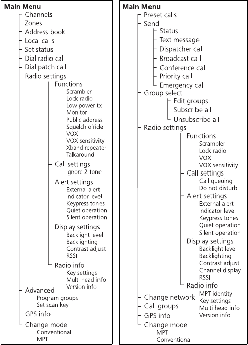
Some of the menus shown below may not be available for your radio.
Menu maps
Conventional mode Trunked mode
17
Contents
About this guide ......................................................................................... 6
For your safety ............................................................................. 7
Safety warnings used in this guide .............................................................. 7
Radio frequency exposure information ........................................................ 7
Controlling your exposure to RF energy ....................................................... 8
Compliance with RF energy exposure standards .......................................... 9
Radio frequency emissions limits in the USA ................................................ 9
Unapproved modifications or changes to radio ............................................ 9
Health, safety and electromagnetic compatibility in Europe ........................ 10
Electromagnetic compatibility in European vehicles ................................... 11
EN 60950 requirements (25 watt radios) ................................................... 11
Interference with electronic devices ........................................................... 11
AS/NZS 4365 requirements ....................................................................... 12
Frequency band reserved for distress beacons ........................................... 12
Safe radio operation ................................................................................. 13
High radio surface temperatures ............................................................... 13
Radio protection when charging the vehicle battery ................................... 13
GPS operation .......................................................................................... 13
Your radio’s settings .................................................................. 15
Getting started ........................................................................... 19
About the radio controls ........................................................................... 19
About the keypad microphone .................................................................. 21
About the hand-held control head ............................................................ 21
Understanding the radio display ................................................................ 23
Understanding the radio indicators ........................................................... 25
Navigating your radio’s menus .................................................................. 27
Viewing your radio’s function key settings ................................................. 29
Sharing a multi-head radio with other users .............................................. 30
Basic operation ........................................................................... 31
Turning the radio on and off ..................................................................... 31
Entering your personal identification number ............................................. 31
Adjusting the speaker volume ................................................................... 32
Turning on control-head backlighting ........................................................ 32
Changing the level of control-head backlighting ........................................ 33
Changing the contrast of the radio display ................................................ 34
About GPS information ............................................................................. 35
Viewing GPS information .......................................................................... 36
About the lone worker feature .................................................................. 37
18
Operating in conventional mode ..............................................41
Selecting a zone ....................................................................................... 41
Selecting a channel ................................................................................... 43
Selecting a group ..................................................................................... 45
Checking that a channel is clear ................................................................ 47
Communicating directly with other radios ................................................. 49
Making a call ........................................................................................... 51
Making a local call ................................................................................... 52
Making a call using your address book ...................................................... 54
Making an emergency call ........................................................................ 56
Receiving a call ........................................................................................ 56
Operating in MPT trunked mode ...............................................57
Changing your operating mode ................................................................. 57
Checking that your network is available .................................................... 59
Changing your network ............................................................................ 59
Making a preset call ................................................................................. 61
About talkgroups and scan groups ............................................................ 63
Making a talkgroup call ............................................................................ 64
Changing group membership .................................................................... 66
Making an emergency call ........................................................................ 69
Dialling a PABX number ........................................................................... 71
Dialling a PSTN number ............................................................................ 71
Receiving a call ........................................................................................ 72
Re-establishing a call ................................................................................ 74
Checking missed calls ............................................................................... 75
About status messages ............................................................................. 77
About text messages ................................................................................ 79
Calls to conventional channels or groups .................................................. 82
Dialling calls in MPT trunked mode ...........................................83
MPT 1343 dialling .................................................................................... 83
Nokia ANN fleet calls ............................................................................... 85
Accessing common MPT trunking functions ............................................... 87
Troubleshooting .........................................................................89
When your radio won’t turn on ................................................................. 89
Removing the microphone ........................................................................ 89
Reinstalling the microphone ...................................................................... 90
Removing the radio from the vehicle ......................................................... 90
Describing the radio’s audible tones .......................................................... 91
Tait general software licence agreement .................................93
Getting started 19
Getting started
This section provides a brief description of your radio’s
controls and indicators and explains how to use the
radio’s menus.
The following topics are covered in this section:
■about the radio controls
■about the keypad microphone
■about the hand-held control head
■understanding the radio display
■understanding the radio indicators
■navigating your radio’s menus
■viewing your radio’s function key settings
■sharing a multi-head radio with other users
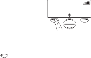
About the radio controls
The radio controls are the PTT key, volume control, on/off key,
scroll keys, selection keys and function keys. Some keys may
have functions assigned to both short and long key presses:
■a short key press is less than one second, and
■a long key press is more than one second.
The radio controls and their functions are summarized in the
following diagram and table.
20 Getting started
scroll keys
on/off key
volume
control
microphone
socket
press-to-talk
(PTT) key
red
display speaker
green
amber
microphone
radio status LEDs
function keys
1 to 4 left selection key right selection key
main menu
Channel 12
Menu
Symbol Name Function
PTT key Press and hold to transmit and release
to listen
Volume control Rotate to change the speaker volume
On/off key Turn the radio on or off with a long press
Left selection key Action determined by the text above the left
selection key, or
deletes a dialled character from the display
Right selection key Action determined by the text above the
right selection key
Scroll keys Scroll up and down through a list of menu
options or scroll left and right in messages
Select your Quick Access menu
Tip: If you press and hold the scroll keys, the scroll speed increases.
Function keys Function keys with programmed options
Getting started 21
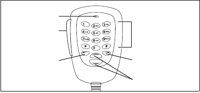
About the keypad microphone
Your radio may have a keypad microphone installed. The
keypad microphone has a PTT key as well as twelve
alphanumeric keys, two scroll keys, and left and right
selection keys.
The PTT key and the scroll and selection keys work in the same
way as those on the control head (see “About the radio
controls” on page 19). The alphanumeric keys are used to
enter letters and numbers.
About the hand-held control head
Your radio may have a hand-held control head installed, to
enable you to operate the radio at a distance from the radio
body. The keys and controls work in the same way as those
on the standard control head and keypad microphone, with
the exception of the volume up and down keys. The hand-
held control head also has two additional function keys.
Note: The hand-held control head may have been
configured to turn the radio on with a PTT press.
The hand-held control head keys and their functions are
summarized in the following diagram and table.
PTT key
(press-to-talk)
microphone
left selection key
scroll keys
alphanumeric keys
right selection key
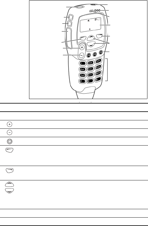
22 Getting started
Zone 11
Channel 12
Talkgr Menu
scroll keys
function key 3
volume up
PTT key
(press-to-talk)
microphone
status LEDs
alphanumeric keys
volume down
function key 2
on/off key
function key 1
display
function keys
4 to 6
left selection key
right selection key
Symbol Name Function
PTT key
Press and hold to transmit and release to listen
Volume up Press to increase the speaker volume
Volume down Press to decrease the speaker volume
On/off key Press to turn the radio on or off
Left selection key Action determined by the text above the left
selection key, or
deletes a dialled character from the display
Right selection key Action determined by the text above the
right selection key
Scroll keys Scroll up and down through a list of menu
options or scroll left and right in messages,
or select your Quick Access menu
Tip: If you press and hold the scroll keys, the scroll speed increases.
Function keys Function keys with programmed options
Alphanumeric keys Used to enter letters and numbers
Getting started 23
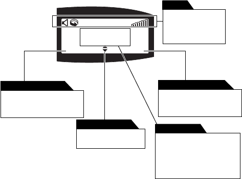
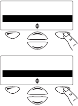
Understanding the radio display
The messages and symbols you see on your radio display
depend on the mode in which your radio is operating and the
way it is programmed.
The following diagram shows a typical display and explains
some of the information that may be available.
This text shows the current
function of the right
selection key.
right selection key text
This text shows the current
function of the left
selection key.
left selection key text
This appears when
scrolling is allowed.
scrolling indicator
The symbols along
the top of the
display show which
functions are active.
symbols
This programmed display
appears when the radio
is idle. This may be one or
two lines of text.
default display
Channel 12
Zone C
Zones Menu
24 Getting started
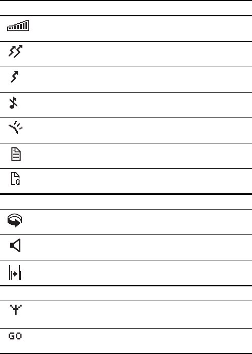
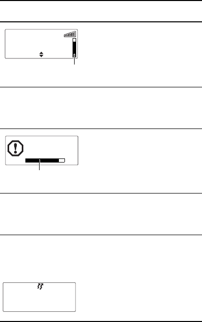
Radio display symbols
These are some of the symbols you may see on you
radio display:
Symbol Meaning
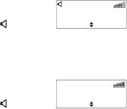
Received signal strength indicator (RSSI): the more bars, the
stronger the signal being received by your radio
Transmit: your radio is transmitting
Low-power transmit: your radio is transmitting on low power
Silent operation: your radio’s audible tones have been turned off
External alert: external alert is active
Call queuing: call queuing is active
Queued call: there are calls in the call queue
Conventional mode symbols:
Scanning: your radio is monitoring a group of channels for activity
(this symbol is animated)
Monitor or squelch override: monitor or squelch override is active
Repeater talkaround: your radio is operating in repeater
talkaround mode
MPT trunked mode symbols:
MPT network: your radio has access to an MPT network
Flashing: your radio is attempting to access an MPT network
Go: your radio has established a call and you are now able to
speak to the other party

Getting started 25
Understanding the radio indicators
The status LED indicators and the radio’s audible tones—
together with the radio display—all combine to give you
information about the state of your radio.
The most common way the indicators work is described in
the following sections.
Note: The way these indicators behave may be affected by
the way your radio is programmed.
Status LED indicators
LED Meaning
red
(transmit)
Glowing: your radio is transmitting
Flashing: your transmit timer is about to expire, or
your radio is stunned
green
(receive)
Glowing: you are receiving activity (conventional mode) or
your radio is actively in a call (MPT trunked mode)
Flashing (conventional mode): you have received a call with
valid special signalling, or you have activated monitor or
squelch override
amber
(scanning or
network)
Glowing: your radio is scanning a group of channels for
activity (conventional mode) or network service is available
(MPT trunked mode)
Flashing: your radio has detected activity on a channel, and
has halted on this channel (conventional mode)
flashing fast: there is no network service available (MPT
trunked mode)

26 Getting started
Audible tones
Note: If quiet or silent mode has been turned on, you will
not hear any audible tones.
For a description of other tones you may hear, see
“Describing the radio’s audible tones” on page 91.
Tone type Meaning
one short
beep
Valid key press: the action you have attempted is
permitted, or
Function activated: a function key has been pressed and
that function has been activated
one long,
low-pitched
beep
Invalid key press: the action you have attempted is not
permitted, or
Transmission inhibited: you have attempted to transmit
but for some reason transmission is not permitted at
this time
one short,
low-pitched
beep
Function deactivated: a function key has been pressed
and the corresponding function has been turned off
Getting started 27
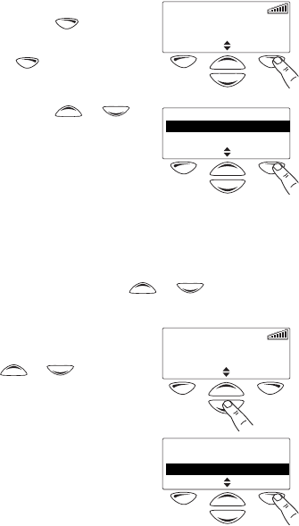
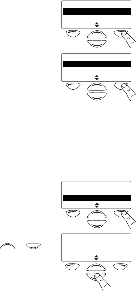
Navigating your radio’s menus
Your radio has a number of menus available, each containing
lists or submenus. The menus available will depend on the
way your radio is programmed.
Using the Main menu
Whenever Menu appears above the
right selection key , you are
able to open the Main menu
by pressing .
Use the scroll keys or to
move through the list of menus.
When the menu you want is
highlighted, press Select to open
the menu you have chosen.
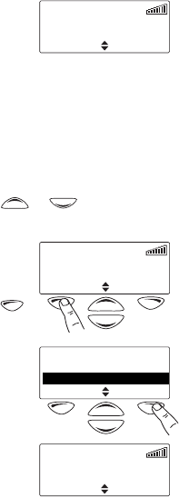
Using the scroll key Quick Access menu
Your radio may be programmed so that your scroll keys act as
a shortcut to a frequently used menu. To go to this Quick
Access menu, press a scroll key or , and the Quick
Access menu appears.
For example, if your Channels menu
is your Quick Access menu, press a
scroll key or to go directly
to the Channels menu.
The Channels menu, with a list of
your available channels and scan
groups, is now displayed.
Channel 1
Menu
Main menu
Channels
Zones
Back Select
Channel 9
Menu
Channels
Channel 92
Scan 1
Cancel Done
28 Getting started
Note: Your scroll keys may be programmed for channel
scroll. If this is the case, press the scroll key to
immediately begin scrolling through your list of
channels.
Using the left selection key Quick Access menu
Your radio may be programmed
so that your left selection key acts
as a shortcut to another frequently
used menu. If this menu has been
programmed, the text for left
selection key corresponds to
the menu.
To use this Quick Access menu, press your left
selection key , and the associated menu appears.
Channel 9
Channels Menu
Getting started 29
Viewing your radio’s function key settings
Your radio’s four function keys can have programmed
functions assigned to each key. Some keys may have a
function associated with both a short key press and a long
key press.
To check the functions assigned to your radio’s function keys,
you can use the Main menu.
1 Select Menu>Radio settings>
Radio info>Key settings.
2In the Key Settings menu, scroll
through the list of function keys.
3Press Select to view details of the function associated
with a particular function key.
The example shown is for a
function key programmed to turn
control-head backlighting on
and off.
Radio info
Key settings
Version info
Back Select
Key settings
Function key 12
Function key 2
Back Select
Backlighting
toggle
30 Getting started
Sharing a multi-head radio with other users
Your radio may be installed with multiple control heads, so
you can share the radio with other users. Elements of the
user interface (such as display content, internal speaker
audio, and LEDs) are duplicated on all control heads. When
sharing the radio with other users:
■wait until other users have finished before using the
radio. The radio may be in use if the red transmit LED is
glowing, there is audio from the speaker, or there is user-
related activity (such as scrolling) on the display.
■you can change the display contrast and the volume
without impacting on other users.
■features such as backlighting and indicator volume apply
to all control heads. Consider other users before changing
these features of the user interface.
Listening to outgoing transmissions
Your radio may be programmed so you can hear outgoing
transmissions initiated from other control heads. You may
need to remove the microphone from the microphone clip to
hear these transmissions.
Identifying your control head type
Some actions apply to the primary control head only, such as
adjusting the volume of a remote speaker.
To check whether your control head
is the primary or secondary head:
1Select Menu>Radio settings>
Radio info>Multi head info.
2Press Select to view the control
head type.
In the example shown, the
control head is the primary head.
Radio info
Key settings2
Multi head info
Back Select
Head status:
primary
Back

Basic operation 31
Basic operation
This section describes the basic operation of your radio.
The following topics are covered in this section:
■turning the radio on and off
■entering your personal identification number
■adjusting the speaker volume
■turning on control-head backlighting
■changing the level of control-head backlighting
■changing the contrast of the radio display
■about GPS information
■about the lone worker feature
Turning the radio on and off
Give a long press of the on/off key to turn the radio either
on or off.
When the radio is first turned on, the red, green and amber
LEDs flash briefly and the radio gives two short beeps. A brief
message may appear in the display.
Note: The hand-held control head may be configured to turn
on with a PTT press.
Entering your personal identification number
You may need to enter a personal
identification number (PIN) before
you can use your radio. If the
message Enter PIN appears, enter
your assigned PIN.
Once you have entered your PIN correctly, the radio sounds
two short beeps and normal operation is now possible.
Enter PIN
32 Basic operation
If you do not know your PIN or
you receive a wrong PIN message,
consult your radio provider or
administrator.
Adjusting the speaker volume
The volume control also changes the volume level of the
radio’s audible indicators.
Note: Your radio may be programmed with a minimum
volume level.
Standard control head
Rotate the volume control clockwise to increase the speaker
volume and counterclockwise to decrease the volume.
Hand-held control head
Press to increase the speaker volume and to decrease
the volume.
Turning on control-head backlighting
The radio’s display and keypad light up when backlighting is
on. This normally only happens when a key is pressed or a
call is received. There are two ways you may be able to
change the way backlighting operates on your radio:
■turn on backlighting momentarily, using a programmed
function key, or
■change backlighting between on and off, using either a
programmed function key or the Main menu.
Turning backlighting on momentarily by using
a function key
You may be able to use a programmed function key to turn
backlighting on momentarily. Backlighting remains on for a
few seconds and then turns off.
Alternatively, the function key may be programmed so that:
Wrong PIN,
try again
Basic operation 33
■a short key press turns backlighting on momentarily, and
■a long key press turns backlighting on, and it remains on
until there is a further long key press.
Turning backlighting on and off by using a
function key
The function key programmed for Backlighting turns
backlighting on and off. When backlighting is turned on, it
remains on until the function key is pressed again.
Turning backlighting on and off by using the
Main menu
When backlighting is turned on using the menu, it remains on
until the setting is changed to off, regardless of radio activity.
1Select Menu>Radio settings>
Display settings>Backlighting.
2In the Backlighting menu,
choose either On or Off.
3Press Select.
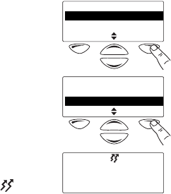
Changing the level of control-head backlighting
The radio’s display and keypad light up when backlighting is
on. This normally only happens when a key is pressed or a
call is received.
You may be able to change the level of control-head
backlighting using the Main menu.
Display settings
Backlight level 2
Backlighting
Back Select
Backlighting
Off 2
On
Back Select
34 Basic operation
1
Select Menu>Radio settings>
Display settings>Backlight level.
2In the Backlight Level menu,
choose either High, Medium
or Low.
3Press Select.
Changing the contrast of the radio display
If the radio’s display is too dark or too light, you may be able
to adjust the contrast by using the Contrast Adjust menu.
1Select Menu>Radio settings>
Display settings>Contrast
adjust.
2In the Contrast Adjust menu, use
the scroll keys or to
adjust the display contrast to the
desired level.
3Press Save to save this setting.
Display settings
Backlight level
Backlighting 2
Back Select
Backlight level
Medium
High 2
Back Select
Display settings
Backlighting2
Contrast adjust
Back Select
Use scroll keys to
adjust
Cancel Save

Basic operation 35
About GPS information
Your radio may be connected to a GPS (global positioning
system) receiver, and programmed (see the note below) so
you can view GPS information such as latitude and
longitude, true course, speed, and coordinated universal
time. Your radio may also be programmed to display UTM
(universal transverse mercator) information such as the UTM
zone, and northing and easting coordinates.
Note: GPS information on the radio display is not a standard
feature. Before being programmed, it must be
purchased and enabled on the radio via the Software
Feature Enabler. Contact Tait Electronics Limited for
more information.
About GPS status information
While viewing GPS information, GPS status information
appears at the top right of the display.
The status information you see on a hand-held control head
may differ to that on a standard control head. In the
following section, status information for a hand-held control
head is shown in brackets [ ].
The following GPS status information may appear in the
display:
■Tracking [trk]: the GPS receiver is communicating with
asatellite.
■Lost cnx [no cnx]: the radio has lost serial
communications with the GPS receiver.
■Stored [no fix]: GPS receiver is having trouble
connecting to a satellite and the radio is displaying stored
information that may not be current.
GPS info tracking
Lat: S 25°28'30"
Long: E 119°38'36"
Exit
s
t
a
t
us
i
n
f
orma
ti
on
36 Basic operation
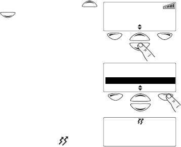
Viewing GPS information
To view GPS information, you may be able to either:
■use a programmed function key, or
■use the Main menu.
Viewing GPS information by using a
programmed function key
1Press the function key programmed for GPS display.
GPS information is now shown in
the display.
2Use the scroll keys or
to view more GPS information.
3Press Exit to exit the GPS display.
Viewing GPS information by using the Main
menu
1Select Menu>GPS info.
2Use the scroll keys or
to view more GPS information.
3Press Exit to exit the GPS
display.
GPS info tracking
Lat: S 25°28'30"
Long: E 119°38'36"
Exit
Main menu
Advanced
GPS info
Back Select
Zone: 50 tracking
Easting: 765773
Northing: 7179810
Exit
GPS info tracking
Lat: S 25°28'30"
Long: E 119°38'36"
Exit
Basic operation 37
About the lone worker feature
The ‘lone worker’ emergency feature is designed for people
who work alone in potentially hazardous environments. Your
radio may be programmed so that lone worker monitoring is
active as soon as your radio is turned on, or you may be able
to turn lone worker on and off.
While lone worker is active, the radio expects a response
from you at regular intervals, and usually prompts you with a
warning beep. Typically, this happens every hour.
If you are unable to respond to this prompt, an audible
warning may be given shortly before the radio sends an
emergency call or enters emergency mode, to warn you and
to prevent false activation.
For a detailed explanation of emergency mode, see “Making
an emergency call” on page 56 (conventional operation) and
“Making an emergency call” on page 69 (trunked
operation).
Note: If the radio is operating in silent mode, then any
audible indicators for lone worker are turned off.
38 Basic operation
Lone worker operation
Lone worker monitoring is made up of three stages. The way
the radio behaves and the duration of each stage depends on
how the radio is programmed. See “Lone worker messages
and indicators” on page 38.
■Stage 1: Lone worker is activated and the user activity
timer begins to count down. This timer is typically set
for 60 minutes, but may be programmed for as long as
5hours.
■Stage 2: The user activity time expires and the
user response timer begins to count down. This timer
is typically set for 10 seconds, but may be programmed
for as long as 1.5 minutes.
■Stage 3: The user response time expires and the radio
sends an emergency call or enters emergency mode.
Lone worker messages and indicators
The following table explains the messages and indicators
that may be associated with the lone worker feature.
Note: Your radio may be programmed so that there is no
visible or audible indication of lone worker operation.
Radio behaviour Explanation
Lone worker has been
turned on.
Lone worker has been
turned off.
Loneworker
activated
Loneworker
deactivated
Basic operation 39
Lone worker is active and
the user activity timer is
counting down.
The radio sounds a
low-pitched beep.
There has been no user
activity and the user activity
time has expired.
The user response timer is
counting down.
The radio sounds a long,
low-pitched beep.
There has been no user
activity and the user
response time has expired.
The radio sounds three short
beeps, rising in pitch and the
message Emergency mode
appears.
The radio has sent an
emergency call and is now
in emergency mode.
Radio behaviour Explanation
user activity
timer symbol
Channel 1
Menu
Loneworker
awaiting
user response
timer symbol
Emergency mode
40 Basic operation
Activating lone worker
To turn the lone worker feature on and off:
■Press the assigned function key.
The message Loneworker activated (or Loneworker
deactivated) appears in the display.
Note: Your radio may be programmed so that lone worker is
active as soon as your radio is turned on.
Responding to a lone worker prompt
When the lone worker user activity timer expires, the
message Loneworker awaiting appears on the display
and you hear a low-pitched beep.
Alternatively, there may not be any visible or audible
indication that the user activity timer has expired.
■Press any key, turn the volume control, briefly press the
on/off key, or press the PTT key. This resets the lone
worker user activity timer.
If you are unable to respond, the user response timer
begins to count down. You now have less than
two minutes to respond before the radio automatically
sends an emergency call or enters emergency mode.
■Press any key, turn the volume control, briefly press the
on/off key, or press the PTT key. This resets the user
activity timer.
If you are unable to respond, the radio sends an
emergency call or enters emergency mode.
Pressing a function key to reset the user
activity or user response timer
When a function key is used to reset either the user activity
or user response timer, the programmed action for the
function key is also activated. For example, if you press the
lone worker function key to reset either timer, then lone
worker is turned off.
Operating in conventional mode 41
Operating in conventional mode
The following topics are covered in this section:
■selecting a zone
■selecting a channel
■selecting a group
■checking that a channel is clear
■communicating directly with other radios
■making a call
■making a local call
■making a call using your address book
■making an emergency call
■receiving a call
Selecting a zone
A zone is a collection of channels and groups. When you
select a zone, only the channels and groups assigned to that
zone are available.
To select a zone you may be able to either:
■use the Main menu, or
■use your Quick Access menu.
Selecting a zone by using the Main menu
1Select Menu>Zones.
2In the Zones menu, scroll
through the list of zones until the
one you want appears.
Main menu
Zones
Local calls
Back Select
Zones
Zone 2 2
Zone 3
Back Select
42 Operating in conventional mode
3Press Select.
The zone indication may be
programmed to appear either
below the channel information
or beside the RSSI symbol.
Selecting a zone by using your Quick
Access menu
Note: Your scroll keys may be programmed for zone scroll. If
this is the case, press the scroll key to immediately
begin scrolling through your list of zones.
1Press one of the scroll keys or to open the
Zones menu.
Alternatively, the left selection
key may be programmed as your
Quick Access menu. In this case,
press the left selection key
to access the Zones menu.
2Scroll through the list of zones
until the zone you want appears.
3Press Select.
The zone indication may be
programmed to appear either
below the channel information
or beside the RSSI symbol.
Channel 9
Zone 3
Menu
Channel 1
Zone 2
Zones Menu
Zones
Zone 2 2
Zone 3
Back Select
Channel 9
Zone 3
Menu
Operating in conventional mode 43
Selecting a channel
To select a channel you may be able to either:
■use a programmed function key,
■use the Main menu, or
■use your quick access menu.
Selecting a channel by using a programmed
function key
Press the function key programmed for preset channel.
The programmed channel is now
shown in the display.
Selecting a channel by using
the Main menu
1Select Menu>Channels.
2In the Channels menu, scroll
through the list of channels until
the channel you want appears.
3Press Done.
The programmed channel is now
shown in the display.
Channel 9
Menu
Main menu
Channels
Zones
Back Select
Channels
Channel 9 2
Scan 1
Cancel Done
Channel 9
Menu
44 Operating in conventional mode
Selecting a channel by using your Quick
Access menu
Note: Your scroll keys may be programmed for channel
scroll. If this is the case, press the scroll key to
immediately begin scrolling through your list of
channels.
1Press one of the scroll keys or to open the
Channels menu.
Alternatively, the left selection
key may be programmed as your
Quick Access menu. In this case,
press the left selection key
to access the Channels menu.
2Scroll through the list of
channels until the channel you
want appears.
3Press Done.
The programmed channel is now
shown in the display.
Channel 8
Channels Menu
Channels
Channel 8 2
Channel 9
Cancel Done
Channel 9
Channels Menu
Operating in conventional mode 45
Selecting a group
A group is a collection of channels that are grouped together
for either scanning or voting. In the Channels menu, the
group is shown as being a single channel item, e.g. “Scan1”.
To select a group you may be able to either:
■use a programmed function key,
■use the Main menu, or
■use your quick access menu.
Selecting a group by using a programmed
function key
Press a function key programmed for group scanning.
The programmed group is now
shown in the display, the amber LED
glows and the scanning symbol
appears in the display.
Selecting a group by using the Main menu
1Select Menu>Channels.
2In the Channels menu, scroll
through the list of channels and
groups until the group you want
appears.
3Press Done.
The amber LED glows and the
scanning symbol appears in
the display.
Scan 1 Menu
Main menu
Channels
Zones
Back Select
Channels
Channel 9 2
Scan 1
Cancel Done
Scan 1 Menu
46 Operating in conventional mode
Selecting a group by using your Quick
Access menu
Note: Your scroll keys may be programmed for channel
scroll. If this is the case, press the scroll key to
immediately begin scrolling through your list of
channels and groups.
1Press one of the scroll keys or to open the
Channels menu.
Alternatively, the left selection
key may be programmed as your
Quick Access menu. In this case,
press the left selection key
to access the Channels menu.
2Scroll through the list of
channels and groups until the
group you want appears.
3Press Done.
The amber LED glows and the
scanning symbol appears in
the display.
Channel 8
Channels Menu
Channels
Channel 8 2
Scan 1
Cancel Done
Scan 1
Channels Menu
Operating in conventional mode 47
Checking that a channel is clear
You or your user group may be segregated from other user
groups by special signalling. If an incoming call carries the
special signalling tones specific to you or your user group,
your radio’s signalling mute opens and you can hear the call.
These tones may not be audible.
The monitor function may allow you to override any special
signalling on a channel, so that you can check that the
channel is clear before you make a call.
Note: Your radio may be programmed to activate monitor
whenever the microphone is off the microphone clip.
To activate monitor, you may be able to either:
■remove the microphone from the microphone clip,
■use a programmed function key, or
■use the Main menu.
Activating monitor by using a function key
1Press the monitor function key to activate monitor and
hear any traffic on the channel.
While monitor is on, the green
LED flashes slowly and the
monitor symbol appears in
the display.
2Press the monitor function key again to turn monitor off,
or wait for monitor to turn off automatically, after a
programmed delay.
When monitor turns off, the
green LED stops flashing and the
monitor symbol disappears
from the display.
Note: Your radio may be programmed so that monitor turns
off automatically after a short time.
Channel 9
Menu
Channel 9
Menu
48 Operating in conventional mode
Activating monitor by using the Main menu
1Select Menu>Radio settings>
Functions>Monitor.
2In the Monitor menu,
choose On.
3Press Select.
While monitor is on, the green
LED flashes slowly and the
monitor symbol appears in
the display.
Note: Your radio may be programmed so that monitor turns
off automatically after a short time.
Functions
Monitor
Public address
Back Select
Monitor
Off 2
On
Back Select
Channel 9
Menu

Operating in conventional mode 49
Communicating directly with other radios
You can bypass the radio repeater and communicate directly
with another radio. This feature is known as repeater
talkaround.
You can do this, for example, when you are out of range of
the repeater, or if the repeater is busy or stops working.
While repeater talkaround is active, all transmissions are
made on the receive frequency of the channel you are on.
To activate repeater talkaround, you may be able to either:
■use a programmed function key, or
■use the Main menu.
Activating repeater talkaround by using a
function key
1Change to the required channel.
2Press the programmed function key to turn repeater
talkaround on.
The message Talkaround
activated appears and the
repeater talkaround symbol
appears in the display.
3Proceed with your call.
4To turn repeater talkaround off, either:
■change the channel, or
■press the function key again.
Talkaround
activated
50 Operating in conventional mode
Activating repeater talkaround by using the
Main menu
1Change to the required channel.
2Select Menu>Radio settings>
Functions>Talkaround.
3In the Talkaround menu,
choose On.
4Press Select.
The message Talkaround
activated appears. The repeater
talkaround symbol appears if
you navigate to the default
display.
5Proceed with your call.
6To turn repeater talkaround off, either:
■change the channel, or
■choose Off in the Talkaround menu and press Select.
Talkaround
Off 2
On
Back Select
Talkaround
activated
Operating in conventional mode 51
Making a call
1Select the required channel or scan group.
2Check that the channel is clear. If the green LED is glowing,
the channel is busy and you may not be able to transmit.
3Once the channel is clear (the green LED is off), lift the
microphone off the microphone clip.
4Hold the microphone about 5cm (2 inches) from
your mouth.
5Press and hold the PTT key to transmit.
6Speak clearly into the microphone and release the PTT
key when you have finished talking.
While you are transmitting, the
red LED glows and the transmit
symbol appears in the
display.
Transmit timer
Your radio may have a transmit timer that limits the amount
of time you can transmit continuously.
When the transmit timer is about to
expire, the message Transmit
timeout imminent appears in the
display, the red LED flashes and the
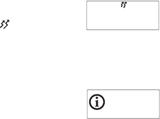
radio gives three beeps.
If the transmit timer has expired, you must release the PTT
before you can transmit again.
Calling...
Dispatcher
Clear
Transmit
timeout
imminent
52 Operating in conventional mode
Making a local call
Each channel on your radio may have one or more local calls
programmed. To make a local call you may be able to either:
■use the Main menu, or
■use your Quick Access menu.
Making a local call by using the Main menu
1Select the required channel.
2Select Menu>Local calls.
3In the Local Calls menu, scroll
through the list of local calls until
the call you want appears.
4Press Send.
The call details appear in the
display, the red LED glows and
the transmit symbol appears
in the display.
Main menu
Local calls
Address book
Back Select
Local calls
Car 2 2
Dispatcher
Back Send
Calling...
Dispatcher
Clear
Operating in conventional mode 53
Making a local call by using your Quick
Access menu
1Select the required channel.
2Press one of the scroll keys
or to open the
Local Calls menu.
3Scroll through the list of local
calls until the call you
want appears.
4Press Send.
The call details appear in the
display, the red LED glows and
the transmit symbol appears
in the display.
Channel 9
Menu
Local calls
Car 2 2
Dispatcher
Back Send
Calling...
Dispatcher
Clear
54 Operating in conventional mode
Making a call using your address book
Your Address Book menu has a programmed list of calls,
which can be made from any channel or zone. Address-book
calls may also be used to send status information, such as
“at lunch” or “on site”.
To make a call using your address book, you may be able
to either:
■use a programmed function key,
■use the Main menu, or
■use your Quick Access menu.
Making an address-book call by using a
function key
Press the function key programmed for Address Book Call.
The call details appear in the display,
the red LED glows and the
transmit symbol appears in
the display.
Making an address-book call by using the
Main menu
1Select Menu>Address book.
2In the Address Book menu, scroll
through the list of calls until the
call you want appears.
Calling...
Base
Clear
Main menu
Local calls 2
Address book
Back Select
Address book
Region 2 2
Base
Back Send
Operating in conventional mode 55
3Press Send.
The call details appear in the
display, the red LED glows and
the transmit symbol appears
in the display.
Making an address-book call by using your
Quick Access menu
1Press one of the scroll keys
or to open the
Address Book menu.
2Scroll through the list of calls
until the call you want appears.
3Press Send.
The call details appear in the
display, the red LED glows and
the transmit symbol appears
in the display.
Calling...
Base
Clear
Channel 9
Menu
Address book
Region 2 2
Base
Back Send
Calling...
Base
Clear
56 Operating in conventional mode
Making an emergency call
You may be able to activate emergency mode by using a
programmed function key.
Note: The emergency function key may be programmed for
either a short key press or long key press.
1Press the function key programmed for Emergency Mode
and an emergency call is sent to your dispatcher, or some
other predetermined location.
While emergency mode is active, your radio may cycle
between receive and transmit, so that your dispatcher
can hear any activity near the radio. Alternatively, your
radio may appear to turn off but will actually remain in
emergency mode.
2Reset the radio to normal operation at any time
by turning the radio off and then on.
Note: Emergency mode may be programmed to end after a
fixed period of time. In this case, there is no need to
turn the radio off and then on in order to return the
radio to normal operation.
Receiving a call
When there is valid activity on your radio’s currently selected
channel or group, the radio then unmutes and you can
hear the call.
If the incoming call contains special signalling that matches
the signalling programmed for your radio, the green LED
flashes and your radio may give a ringing tone.
Operating in MPT trunked mode 57
Operating in MPT trunked mode
Note: Your radio must have trunking functionality
programmed before it can operate in MPT
trunked mode.
The following topics are covered in this section:
■changing your operating mode
■checking that your network is available
■changing your network
■making a preset call
■about talkgroups and scan groups
■making an emergency call
■dialling a PABX number
■dialling a PSTN number
■receiving a call
■re-establishing a call
■checking missed calls
■about status messages
■about text messages
■calls to conventional channels or groups
Changing your operating mode
The way your radio performs basic functions, such as sending
and receiving calls, depends on the operating mode of your
network. The two operating modes that may be available on
your radio are conventional mode (see “Operating in
conventional mode” on page 41), and MPT trunked mode.
To change your radio’s operating mode, you may be able
to either:
■use a programmed function key, or
■use the Main menu.
58 Operating in MPT trunked mode
Using a function key to change operating mode
Press the function key programmed to change modes and the
radio shows the programmed default display for either
conventional or MPT trunked mode.
Using the Main menu to change operating mode
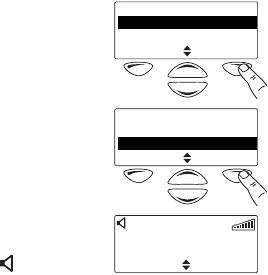
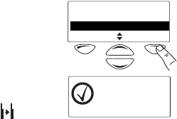
1Select Menu>Change mode.
2In the Change Mode menu,
select either Conventional
or MPT.
3Press Select.
4Press Yes when you are prompted to confirm
your selection.
Your radio restarts, and shows
the programmed default display
for either conventional or MPT
trunked mode.
Main menu
GPS info2
Change mode
Back Select
Change mode
Conventional 2
MPT
Back Select
300 3078 234
Calls Menu
234
Operating in MPT trunked mode 59
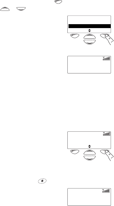
Checking that your network is available
Check that the amber LED is glowing and the network
symbol appears in the display. The amber LED glows and
the network symbol is shown whenever your radio has
access to the MPT trunked network.
If the amber LED and the network symbol are flashing, your
radio is attempting to access the MPT trunked network. If
these indicators remain flashing, your radio may be out of
the network coverage area.
Changing your network
Your radio may be programmed to operate on different
trunking networks. You may wish to change networks
because you are out of the network coverage area, or you
need to have access to another trunking network.
To change your radio’s operating network, you may be able
to either:
■use the Main menu, or
■dial the new network using the alphanumeric keys.
Using the Main menu to change networks
1Select Menu>Change network.
2In the Change Network menu,
scroll through the list of
networks until the network you
want appears.
3Press Select.
The radio will restart, and display a power-up message
followed by the name of the new network.
Main menu
Change network
Call groups
Back Select
Change network
Network 12
Network 2
Back Select

60 Operating in MPT trunked mode
4Check that the amber LED is glowing and the network
symbol appears in the display. If the amber LED and
network symbol keep flashing, you may be out of the
coverage area of this network.
Dialling a new network
Note: This feature is only available for radios with
alphanumeric keys.
1Dial *700# to display the name of the current trunked
network.
2Dial *70n# to change to a new network, where n is the
number of the new network.
The radio will restart, and display a power-up message
followed by the name of the new network.
3Check that the amber LED is glowing and the network
symbol appears in the display. If the amber LED and
network symbol keep flashing, you may be out of the
coverage area of this network.
Operating in MPT trunked mode 61
Making a preset call
The preset calls programmed for your radio may be to other
radios, to PABX extensions or to PSTN numbers. To make a
preset call from your radio, you may be able to either:
■use a programmed function key,
■use the Main menu,
■use your Quick Access menu, or
■dial the preset call using the alphanumeric keys.
Using a function key to make a preset call
Press the function key programmed to make the preset call
you want.
The call details appear in the display.
While the call is being setup, you
can cancel the call by
pressing Clear.
Using the Main menu to make a preset call
1Select Menu>Preset calls.
2In the Preset Calls menu, scroll
through the list of calls until the
call you want appears.
3Press Send.
The call details appear in the
display. While the call is being
setup, you can cancel the call by
pressing Clear.
Calling...
Car 2
Clear
234
Main menu
Preset calls
Send
Back Select
Preset calls
Car 12
Car 2
Back Send
Calling...
Car 2
Clear
234
62 Operating in MPT trunked mode
Using your Quick Access menu to make a
preset call
1Press the left selection key or one of the scroll keys
or to enter the Preset Calls menu.
2Scroll through the list of names
until the you want appears.
3Press Send.
The call details appear in the
display. While the call is being
setup, you can cancel the call by
pressing Clear.
Dialling a preset call
Note: This feature is only available for radios with
alphanumeric keys.
The preset calls programmed for your radio can be dialled if
you know the number associated with the preset call.
To dial a preset call:
1Dial p, where p is the number of
the preset call.
If your preset call number is the
same as a call to another radio,
then you need to dial a leading
0. For example, dial 23# to call radio 23 and dial 023#
for preset call number 23.
2Press Send or the or PTT key.
The call details appear in the
display. While the call is being
setup, you can cancel the call by
pressing Clear.
Preset calls
Car 12
Car 2
Back Send
Calling...
Car 2
Clear
234
4
Clear Send
234
Calling...
4
Clear
GO 234
Operating in MPT trunked mode 63
About talkgroups and scan groups
A trunked radio system may consist of a many fleets of
radios, each with a number of talkgroups and scan groups.
A talkgroup consists of radio users either within the same
fleet, or across multiple fleets. A scan group is a group of
talkgroups.
When your radio belongs to a talkgroup or scan group, it is
said to be “subscribed”, and you receive all calls directed to
that group of users.
The diagram below shows a typical trunked radio system
with fleets, talkgroups and a scan group.
Fleets
Talkgroups
Scan group
64 Operating in MPT trunked mode
Making a talkgroup call
To make a talkgroup call, you may be able to either:
■use the Main menu, or
■dial the talkgroup call using the alphanumeric keys.
Using the Main menu to make a talkgroup call
1Select Menu>Call groups.
2In the Call Groups menu, scroll
through the list of talkgroups
until the talkgroup you want
appears.
Note: Scan groups do not appear in
this list, as it is not possible
to call a scan group.
3Press Send to call the talkgroup.
The call details appear in the
display. While the call is being
setup, you can press Clear to
cancel the call.
Main menu
Call groups
GPS info
Back Select
Call groups
9912
992
Back Send
Conference to
992
Clear Menu
234
Operating in MPT trunked mode 65
Dialling a talkgroup call
Note: This feature is only available for radios with
alphanumeric keys.
The way you dial talkgroup calls depends on the dialling
scheme your network uses. See “Dialling calls in MPT
trunked mode” on page 83 for more information on
different ways to dial talkgroup calls.
1Dial g, where g is the number
associated with the talkgroup.
2Press Send or the or
PTT key.
The call details appear in the
display. While the call is being
setup, you can press Clear to
cancel the call.
992
Clear Send
234
Conference to
992
Clear Menu
234

66 Operating in MPT trunked mode
Changing group membership
There are two methods of changing your membership of
talkgroups or scan groups. You may be able to either:
■use you Quick Access menu to join a single talkgroup or
scan group, or
■use the Main menu to change your membership of
multiple groups.
Selecting a new group using your Quick
Access menu
You may be able to use your Quick Access menu to select a
new talkgroup or scan group. Selecting a new group means
that the previously selected group is automatically deselected.
To select a talkgroup or scan group:
1Press the left selection key
to enter the Groups menu.
The currently selected talkgroup
or scan group has + beside it.
2Scroll through the list of groups,
until the talkgroup or scan group
you want to select appears.
3Press Join or wait for three
seconds.
The previous group is deselected
and the new talkgroup ID may
appear in the display.
To make a call to the talkgroup shown, you may be able
to briefly press the PTT key.
Note: It is not possible to make a call to a scan group, but
you can call any of its constituent groups.
Talkgroup
994
Talkgrp Menu
234
Groups
992
Scan1 +
Back Join
Talkgroup
992
Talkgrp Menu
234
Operating in MPT trunked mode 67
Changing group membership using the
Main menu
Your radio may be programmed with permanent or user-
selectable talkgroups and scan groups. If any talkgroup or
scan group is user-selectable, you can choose to unsubscribe
from that group or subscribe to it.
To change your group membership:
1Select Menu>Group
select>Edit groups.
2In the Groups menu, scroll
through the list of groups. In
the Groups list, the group
membership status of a group is
show in the following way:
■a + symbol shows that you
are currently a member of the group. Note that if you
are a member of a scan group, all the members of the
scan group also have a + beside them.
■a P symbol shows that this is a permanent group
whose membership cannot be changed.
■If there is no symbol beside the group, then the radio
is currently unsubscribed from this group.
3Press Change and the + beside the group is either
added or removed.
4When you have made the required changes in the Groups
list, press Back to exit the Groups menu.
The new group ID may appear in
the display, or if more than one
group has been selected, the
display show Multi.
Group select
Edit groups
Subscribe all
Back Select
Groups
992 +
Scan1 P
Back Change
Talkgroup
Multi
Menu
234
68 Operating in MPT trunked mode
Subscribing or unsubscribing to all groups
To either subscribe or unsubscribe to all user-selectable
talkgroups and scan groups:
1Select Menu>Group
select>Subscribe all.
The message Subscribed to all
groups briefly appears in the
display, and your display may
now show that you are
subscribed to all programmed groups.
2Select Menu>Group
select>Unsubscribe all.
3Press OK when you are
prompted to confirm your
selection.
The message Unsubscribed
from all groups briefly appears
in the display, and your display
may now show that you are not
subscribed to any groups.
Group select
Subscribe all
Unsubscribe all
Back Select
Talkgroup
All
Menu
234
Group select
Unsubscribe all
Edit groups
Back Select
Unsubscribe
to all groups?
Cancel OK
Talkgroup
None
Menu
234
Operating in MPT trunked mode 69
Making an emergency call
In an emergency you may be able to summon help by
sending an emergency call.
On most networks, an emergency call takes precedence over
other call types, and existing calls are cleared down so that
the emergency call can proceed.
To make an emergency call from your radio, you may be able
to either:
■make a preset emergency call,
■dial the emergency call using the alphanumeric keys.
After making the call, your radio may be programmed to
enter emergency mode. While emergency mode is active,
your radio may cycle between receive and transmit, so that
your dispatcher or the called party can hear any activity near
your radio.
To activate emergency mode, you may be able to:
■use a function key programmed for emergency mode, or
■use a hidden switch.
Making a preset emergency call
To make a preset emergency call from your radio, you may be
able to either use a programmed function key, use the main
menu, or use your quick access menu.
1Select your preset emergency call.
See “Making a preset call” on page 61.
2Press Send.
An emergency call is now sent to the emergency location
that has been programmed for your radio.
70 Operating in MPT trunked mode
Dialling an emergency call
Note: This feature is only available for radios with
alphanumeric keys.
1Dial *9.
2
Press
Send
or the or PTT key.
An emergency call is now sent to
the emergency location that has
been programmed for your radio.
Note: If you wish to send an emergency call to another
radio, you may be able to dial *9*n then press the
or PTT key. In this case, n is the radio unit
number you wish to send the emergency call to and
may be a two- or three-digit number.
Activating emergency mode
You can activate emergency mode using a function key
programmed for emergency mode. Alternatively, you may be
able to activate emergency mode using a hidden switch or
panic button.
Note: The emergency function key may be programmed for
either a short key press or long key press.
Once emergency mode is activated, your radio makes an
emergency call to your dispatcher or some other
predetermined location. The radio then enters emergency
mode. While emergency mode is active, your radio may cycle
between receive and transmit, so that your dispatcher can
hear any activity near the radio.
Cancelling emergency mode
Reset the radio to normal operation at any time by turning
the radio off and then on.
Emergency mode may be programmed to end after a fixed
period of time. In this case, there is no need to turn the radio off
and then on in order to return the radio to normal operation.
*9
Clear Send
234
Operating in MPT trunked mode 71
Dialling a PABX number
Note: This feature is only available for radios with
alphanumeric keys.
1Dial n, where n is the PABX
extension you wish to call.
2Press Send or the or
PTT key.
The call details appear in the
display. While the call is being
setup, you can cancel the call by
pressing Clear.
Dialling a PSTN number
Note: This feature is only available for radios with
alphanumeric keys.
1Dial 0n, where n is the PSTN
number you wish to call.
Note: The numbers you dial before
the 0 depend on the way
your network operates.
2Press Send or the or PTT key.
The call details appear in the
display. While the call is being
setup, you can cancel the call by
pressing Clear.
8789
Clear Send
234
Calling...
8789
Clear
GO 234
033456798
Clear Send
234
Calling...
033456798
Clear
GO 234
72 Operating in MPT trunked mode
Receiving a call
When you receive a call, your radio
displays the caller’s identity and
responds in one of two ways,
depending on the way it was
programmed and the way your network operates.
■On-air call setup: The radio gives a ring and automatically
accepts the call. The symbol appears in the display.
■Full off-air call setup (FOACSU): When a call is received,
the radio rings like a telephone.
To accept the call, press Answer. The radio gives a beep
and the symbol appears in the display. You may also
be able to accept the call if you briefly press the PTT key
or lift the microphone or hand-held control head off
the clip.
Once the symbol appears, you can proceed with the call,
as follows:
1Hold the microphone about 5cm (2 inches) from
your mouth.
2Press and hold the PTT key to transmit.
3Speak clearly into the microphone and release the PTT
key when you have finished talking.
While you are transmitting, the
red LED glows and the transmit
symbol appears in
the display.
4End the call by placing your microphone back onto its
hook or by pressing Clear. The network may also end the
call if neither you nor the other party transmits for a
predetermined time or if your call time limit is exceeded.
Incoming call
Car 2
Decline Answer
234
11:49
Car 2
Clear
GO 234
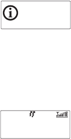
Operating in MPT trunked mode 73
Transmit timer
Your radio may have a transmit timer that limits the amount
of time you can transmit continuously.
When the transmit timer is about to
expire, the message Transmit
timeout imminent appears in the
display, the red LED flashes and the radio gives three beeps.
If the transmit timer expires, the call clears down.
Call time limit
In MPT trunked mode, the length of your call may be limited
by the network or by your radio. Your radio may be
programmed to display the time remaining for your call.
When your call time is about to
expire, the message Call timeout
appears in the display, the red LED
flashes and the radio gives a repeated beep.
Transmit
timeout
imminent
00:05
Call timeout
Clear
GO 234
74 Operating in MPT trunked mode
Re-establishing a call
The last number recall, unanswered call and callback
functions allow you to re-establish calls using the PTT key.
Last number recall
When an outgoing call has ended, the message Last call to
and the called unit’s identity may appear on the display.
To make a call to that person again, briefly press the PTT key.
Unanswered call
When an incoming call is missed, the message
Missed call and the caller’s identity may appear in
the display.
To return the call, briefly press the PTT key.
Callback
When an incoming call has been ended, the message
Last call from and the caller’s identity may appear in
the display.
To make a call to that person, briefly press the PTT key.
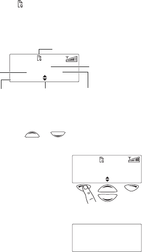
Operating in MPT trunked mode 75
Checking missed calls
If you have missed an incoming call, it may be stored in the
call queue, so that you can return the call later. Information
about the last missed call is shown in the display and the
queued call symbol appears.
In the example below, the last call received was a status
message from Car1. This call is the first of three calls stored
in the call queue.
Accessing the call queue
1Use the scroll keys or to move through the
calls in the call queue until the call you want appears.
2Press Options to open the call
options menu.
The options available for the call
depend on the type of call it is. If
the call is a voice call, select Call
to return the call or Delete to delete the call.
If the call is a status message or
a text message, then select
View to read the message.
identity of last
unanswered caller
scroll through
the calls
type of call
position of call in
the call queue
options available
depend on type of call
queued calls
Car 1
Status 1/3
Options Menu
234
Car 1
Status 1/3
Options Menu
234
Meet you on site
at 13:00 (Car 2)
Cancel Save

76 Operating in MPT trunked mode
Changing your call queuing setting
Your radio may be programmed so that you are able to
change call queuing to “unanswered”. Unanswered call
queuing means that all status and text messages are
immediately queued. Incoming voice calls are only queued if
they are unanswered. An unanswered call is one that is
ended by the radio making the call before the radio receiving
the call has responded in any way.
If your radio has alphanumeric keys, you may be able to
change your call queuing setting using the keypad.
To activate call queuing:
■select Menu>Radio settings>Call settings>Call queuing
and choose On, or
■dial *48 then press the or PTT key.
The message Call queuing activated appears.
To change call queuing to unanswered call queuing:
■select Menu>Radio settings>Call settings>Call queuing
and choose Off, or
■dial #48 then press the or PTT key.
The message Call queuing deactivated appears.
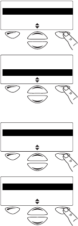
Operating in MPT trunked mode 77
About status messages
A status message is sent to another party to indicate your
current activity or location, such as “en route” or “at lunch”.
If the radio receiving your message has been programmed
with the same status messages, it will decode and display
your message. If you receive a status message, the message
is automatically queued, since a response is not expected.
Selecting a status message
1Select Main>Send>Status.
2In the Status menu, scroll
through the list of status
messages until the message you
want appears.
Sending a status message
1When you have chosen a
message, press Options and the
Send To menu opens.
2In the Send To menu, scroll
through the list of options until
the choice you want appears.
Note: If your radio has
alphanumeric keys, you can
choose the option Send to dialled, then dial the
number of the party you wish to call.
Send
Status
Text message
Back Select
Status
At lunch 2
On site
Back Options
Send to
Send to preset
Send to dialled
Back Select
Preset calls
Car 2
Dispatcher
Back Send
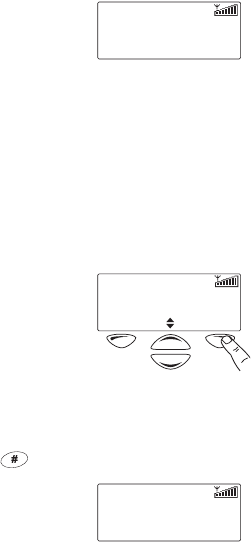
78 Operating in MPT trunked mode
3Press Send.
The call details appear in the
display. While the call is being
setup, you can cancel the call by
pressing Clear.
Dialling a status message
Note: This feature is only available for radios with
alphanumeric keys.
The status messages programmed for your radio can be
dialled if you know the number associated with the
status message.
To dial a status message:
1Dial *0s*n, where s is the
number of the status message
and n is the radio unit number
you wish to send the
message to.
2Alternatively, dial *0s*p, where p is the number of a
preset call. See “Dialling a preset call” on page 62 for
more information.
3Press Send or the or PTT key.
The call details appear in the
display. While the call is being
setup, you can cancel the call by
pressing Clear.
Calling...
*02*Car 2
Clear
234
*030*590
Clear Send
234
Calling...
*030*590
Clear
234
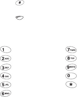
Operating in MPT trunked mode 79
About text messages
Your radio may be programmed so that you can send
text messages. There are three options for creating
text messages:
■selecting a preset text message,
■editing a preset text message, or
■creating a new text message.
Note: To either edit or enter a text message, your radio must
have alphanumeric keys.
Using the alphanumeric keys to enter text
When the alphanumeric keys are used to enter a text
message, they have special functions.
■Use key to toggle between upper and lower case
characters.
■Use to delete a character from the display.
Repeated presses of these keys will give you the characters
shown in the following table.
Key Characters Key Characters
.,?!1 P QRS7
ABC2 T UV8
DEF 3 W XYZ9
GHI 4 space 0
JKL5 *
MN O 6
80 Operating in MPT trunked mode
Selecting a preset text message
1Select Menu>Send>
Text message>Preset message.
In the Preset Message menu, a
short label representing each
message is displayed.
2Scroll through the list of preset
message labels until the one you
want appears.
3Select Edit, and the complete
text message you have chosen is
now displayed.
Editing a preset text message
1Select Menu>Send>
Text message>Preset message.
In the Preset Message menu, a
short label representing each
message is displayed.
2Scroll through the list of preset
message labels until the one you
want appears.
3Press Edit, and the complete
text message you have chosen is
now displayed.
4Use the scroll keys or
to move through the characters.
Use the alphanumeric keys to
add characters and the Clear key to delete them. The
message can be up to 100 characters long.
Text message
Preset message
New message
Back Select
Preset message
Out for lunch 2
Returning base
Back Edit
Returning to base
Clear Options
Text message
Preset message
New message
Back Select
Preset message
Out for lunch 2
Returning base
Back Edit
Returning to base
Clear Options
Returning to base at
1400
Clear Options
Operating in MPT trunked mode 81
Creating a new text message
1Select Menu>Send>
Text message>New message.
The last text message you sent
may be displayed.
2In the New Message menu,
modify the last text message you
sent, or enter the new text
message using the alphanumeric keys. The message can
be up to 100 characters long.
Sending a text message
1When you have chosen or entered a message, press
Options and the Send To menu opens.
2In the Send To menu, scroll
through the list of options until
the choice you want appears.
If your radio has alphanumeric
keys, you can choose the option
Send to dialled, then dial the
number of the party you wish
to call.
3Press Send.
The call details appear in the
display. While the call is being
setup, you can cancel the call by
pressing Clear.
Text message
Preset message 2
New message
Back Select
Meet you on site at 1300
Clear Options
Send to
Send to preset
Send to dialled
Back Select
*2*Meet y
ou on site at 1300*590
Clear Send
234
Preset calls
Car 2
Dispatcher
Back Send
Calling...
*2*Meet you...
Clear
234

82 Operating in MPT trunked mode
Calls to conventional channels or groups
You may be able to dial conventional channels or groups,
using 101 to 110. The channels or groups called using these
numbers are programmed for your radio.
To call a conventional channel or group:
1Dial the number for the channel or group you wish to call.
2Press Send or the or PTT key.
Your radio switches to the conventional channel
programmed for that number.

Dialling calls in MPT trunked mode 83
Dialling calls in MPT trunked mode
If your radio has alphanumeric keys, you can make dialled
calls from your radio. The numbers you dial and dialling
features available depend on the way your radio is
programmed and the way your network operates. Contact
your radio provider for further assistance.
The following topics are covered in this section:
■MPT 1343 dialling
■Nokia ANN fleet calls
■accessing common MPT trunking functions
MPT 1343 dialling
If your MPT trunked network uses the MPT 1343 dialling
scheme, your radio’s unique number on the network
consists of:
■a three-digit prefix,
■a four-digit fleet number, and
■a two- or three-digit radio unit number.
You may also be part of a group, with a two- or three-digit
group number.
Finding your radio’s MPT number
To find your radio’s full MPT number:
1Dial *700.
2Press the or PTT key.
The name associated with your
network and your radio’s full
MPT number appears.
The number is in the form:
Network 1
300-3078-234
Back
Radio unit number
234
Prefix
300 Fleet
3078
Radio unit number
234
84 Dialling calls in MPT trunked mode
MPT 1343 dialled calls
The following table summarizes the way you dial calls to
other radios and groups of radios and gives an example of
each type of call.
Note: In the following examples, the final # may be replaced
by a short press of the PTT key.
Call to Dialling code and example
Radio 23 in the same fleet as you
Radio 234 in the same fleet as you
Radio 23 in fleet 3078 with the
same prefix as you
Radio 234 in fleet 3078 with the
same prefix as you
Radio 234 in fleet 3078 with a
different prefix to you (300)
Group 92 in the same fleet as you
Group 923 in the same fleet as you
Radio unit number
23 #
Radio unit number
234 #
Fleet
3078
Radio unit number
23 #
Fleet
3078 #
Radio unit number
234
Prefix
300
Radio unit number
234 #
Fleet
3078
Group
92
#
Group
923
#

Dialling calls in MPT trunked mode 85
Nokia ANN fleet calls
If your MPT trunked network uses Nokia ANN dialling, the
numbers you dial depend on your fleet size. Fleets are
defined as either large, small or mini. Your radio’s unique
number on the network consists of:
■a lead number 7, 8 or 9, depending on the fleet size,
■a zero-, one-, two- or three-digit prefix,
■a one- or two-digit fleet number, and
■a two- or three-digit radio unit number.
Note: See your radio provider or network administrator for
Nokia ANN call details.
Finding your radio’s MPT number
To find your radio’s full MPT number:
1Dial *700.
2Press the or PTT key.
The name associated with your
network and your radio’s full
MPT number appears.
The number is in the form:
Network 1
7342209
Back
Radio unit number
209
Prefix
34 Fleet
2
Lead
7
86 Dialling calls in MPT trunked mode
Nokia ANN dialled calls
The following table summarizes the way you dial calls to
other radios and gives an example of each type of call.
Note: In the following dialled numbers, the # terminator is
not necessary if you press the PTT key instead.
Call to Dialling code and example
Radio 23 in the same
fleet as you
Group 923 in the same
fleet as you
Large fleet:
Call to radio 234 in
fleet 1 with the same
prefix as you
Call to radio 235 in
fleet 2 with a different
prefix to you (32)
Small fleet:
Call to radio 23 in
fleet 51 with the same
prefix as you
Call to radio 23 in
fleet 52 with a different
prefix to you (126)
Mini fleet:
Call to radio 23 in
fleet 80 with the same
prefix as you
Call to radio 23 in
fleet 81 with a different
prefix to you (3)
Radio unit number
23 #
Group
923
#
Lead
7#
Radio unit number
234
Fleet
1
Lead
7#
Radio unit number
235
Prefix
32
Fleet
2
Lead
7#
Radio unit number
23
Fleet
51
Lead
7#
Radio unit number
23
Prefix
126
Fleet
52
Lead
7, 8 or 9 #
Radio unit number
23
Fleet
80
Lead
7, 8 or 9 #
Radio unit number
23
Prefix
3
Fleet
81

Dialling calls in MPT trunked mode 87
Accessing common MPT trunking functions
The following tables explain how you can access special MPT
trunking functions using the * and # keys. The availability of
these functions is dependant on the way your radio is
programmed and the way your network operates.
Note: In the following examples, the final # may be replaced
by a short press of the PTT key.
*... # functions
Dialling
code
Functions Example
#Accept an incoming FOACSU call
*# Clear call or displayed item, or decline an
incoming FOACSU call
*0#
#0#
Request base dispatcher to call you back
Cancel request
*0*n#
#0*n#
Request another dispatcher to call you back
Cancel request
*0*234#
#0*234#
*0s*n#
*0s#
Status call (s = status 1 to 30) to radio n
Status call to dispatcher
*015*23#
*015#
*1*g# Conference call to group g*1*92#
*11*g# Broadcast call to group g*11*92#
*31*n# Non-prescribed data call *31*23#
*41*n#
#41#
Divert own calls to radio n
Cancel divert
*41*23#
*41*0n#
#41#
Divert own calls to PSTN n
Cancel divert
*41*03456798#
*44*n*m#
#44*n#
Divert 3rd party calls n to m
Cancel divert of 3rd party calls
*44*23*21#
#44*23#

88 Dialling calls in MPT trunked mode
*48#
#48#
Queue incoming calls
Cancel queue
*49#
#49#
Do not disturb
Cancel do not disturb
*491#
#491#
Do not disturb - voice calls only
Cancel do not disturb, voice calls only
*492#
#492#
Do not disturb - data calls only
Cancel do not disturb, data calls only
*50*n# Select channel n (site-select diagnostic function, enabled
during programming)
#50# Resume normal channel hunting (site-select diagnostic function,
enabled during programming)
*700# Display your MPT number and current
network
*70n# Change to network n (1 to 4) *702#
*8*n# Priority call to radio n*8*23#
*8*1*g# Priority conference call to group g *8*1*923#
*9*n# Emergency call to radio n*9*23#
*9*1*g# Emergency conference call to group g *9*1*92#
**n# Abbreviated dialled codes (1-49) **3#
*... # functions
Dialling
code
Functions Example

Troubleshooting 89
Troubleshooting
The following topics are covered in this section:
■when your radio won’t turn on
■removing the microphone
■reinstalling the microphone
■removing the radio from the vehicle
■describing the radio’s audible tones
When your radio won’t turn on
If the red, green and amber LEDs on the control head do not
light up when the radio is turned on, it is likely that no power
is reaching the radio. Check the following:
■Is the power connector firmly plugged into the rear of
the radio?
■Are the in-line fuses in good condition?
■Is the power cable securely connected to the vehicle bat-
tery or power supply?
If all appears to be in order, then contact your radio provider
for further assistance.
Removing the microphone
1
Using your thumb or forefinger, lift up one
of the corners of the microphone grom-
met. Firmly (but gently) pull that corner
until the seal comes away from the cavity.
2Repeat to expose another corner.
3Pull the exposed corners back and slide the grommet up
the microphone cable to reveal the microphone plug.
4Remove the plug from the microphone socket.
grommet
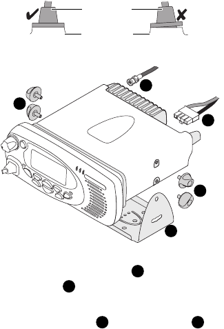
90 Troubleshooting
Reinstalling the microphone
Caution: The microphone grommet must be installed when-
ever the microphone is plugged into the micro-
phone socket.
1Plug the microphone into the microphone socket.
2Slide the microphone grommet along the microphone
cord and push two adjacent corners of the grommet into
the microphone socket cavity.
3Squeeze the grommet and push the remaining corners
into position.
4Check that the grommet is seated correctly in the cavity.
Removing the radio from the vehicle
1Switch off the radio.
2Unscrew the four thumb screws that secure the radio
to the U-bracket .
3Carefully lift the radio clear of the U-bracket.
4Disconnect the antenna and power cable from
the rear of the radio.
microphone
grommet
control head
c
d
a
a
b
a
b
cd

Troubleshooting 91
Describing the radio’s audible tones
The following table summarizes the radio’s audible tones.
Action and tone Meaning
two short
beeps
Radio turned on: the radio is powered on and
ready to use
one short beep after
the power-up beeps
Radio locked: you need to enter your personal
identity number (PIN) before you can use the radio
one long, low-
pitched beep
Radio PIN entry unsuccessful: you need to re-enter
your PIN
two short beeps Radio PIN entry successful: the radio is now ready
to use
one short beep
Function activated: a function key has been pressed
and that function has been initiated
one short, low-
pitched beep
Function deactivated: a function key has been
pressed and the corresponding function has been
turned off
one long, low-
pitched beep
Invalid key press: the action you have attempted is
not permitted, or
Transmission inhibited: you have attempted to
transmit but for some reason transmission is not
permitted at this time
one short, high-
pitched beep
Radio is stunned: the radio has been made inoper-
able by your service provider
two short beeps Radio is revived: the radio has been made opera-
ble by your service provider
three beeps Transmit timeout imminent: in 10 seconds your
transmit timer will expire and your current trans-
mission will be terminated
one high-pitched beep Call timeout imminent: your call time is about to
expire (MPT trunked mode only)

92 Troubleshooting
two low-
pitched beeps
Radio's temperature is high: the radio's temperature is
in the high-temperature range, but the radio will
continue to operate
two high-pitched beeps Radio's temperature is very high: the radio's
temperature is in the very high temperature range
and all transmissions will now be at low power; if
the radio's temperature rises outside this range,
transmissions will be inhibited
continuous low-
pitched tone
Radio system error: a system error has occurred
and the radio may be inoperable
two long low-high
pitched tone pairs
Synthesizer is out-of-lock: the radio's synthesizer
is out-of-lock on the current channel and you
cannot operate on that channel
Action and tone Meaning
Tait general software licence agreement 93
Tait general software licence agreement
This legal document is an Agreement
between you (the “Licensee”) and Tait Elec-
tronics Limited (“Tait”). By using any of the
Software or Firmware items prior-installed in
the related Tait product, included on CD or
downloaded from the Tait website, (hereinaf-
ter referred to as “the Software or
Firmware”) you agree to be bound by the
terms of this Agreement. If you do not agree
to the terms of this Agreement, do not install
and use any of the Software or Firmware.
If you install and use any of the Software or
Firmware that will be deemed to be accept-
ance of the terms of this licence agreement.
The terms of this Agreement shall apply
subject only to any express written terms of
agreement to the contrary between Tait and
the Licensee.
Licence
TAIT GRANTS TO YOU AS LICENSEE THE NON-EXCLU-
SIVE RIGHT TO USE THE SOFTWARE OR FIRMWARE ON
A SINGLE MACHINE PROVIDED YOU MAY ONLY:
1COPY THE SOFTWARE OR FIRMWARE INTO ANY
MACHINE READABLE OR PRINTED FORM FOR
BACKUP PURPOSES IN SUPPORT OF YOUR USE OF
THE PROGRAM ON THE SINGLE MACHINE (CERTAIN
PROGRAMS, HOWEVER, MAY INCLUDE MECH-
ANISMS TO LIMIT OR INHIBIT COPYING, THEY ARE
MARKED “COPY PROTECTED”), PROVIDED THE
COPYRIGHT NOTICE MUST BE REPRODUCED AND
INCLUDED ON ANY SUCH COPY OF THE SOFTWARE
OR FIRMWARE;
AND / OR
2MERGE IT INTO ANOTHER PROGRAM FOR YOUR USE
ON THE SINGLE MACHINE (ANY PORTION OF ANY
SOFTWARE OR FIRMWARE MERGED INTO ANOTHER
PROGRAM WILL CONTINUE TO BE SUBJECT TO THE
TERMS AND CONDITIONS OF THIS AGREEMENT).
THE LICENSEE MAY NOT DUPLICATE, MODIFY,
REVERSE COMPILE OR REVERSE ASSEMBLE ANY SOFT-
WARE OR FIRMWARE IN WHOLE OR PART.
Important Notice
THE SOFTWARE OR FIRMWARE MAY CONTAIN OPEN
SOURCE SOFTWARE COMPONENTS (“OPEN SOURCE
COMPONENTS”). OPEN SOURCE COMPONENTS ARE
EXCLUDED FROM THE TERMS OF THIS AGREEMENT
EXCEPT AS EXPRESSLY STATED IN THIS AGREEMENT
AND ARE COVERED BY THE TERMS OF THEIR RESPEC-
TIVE LICENCES WHICH MAY EXCLUDE OR LIMIT ANY
WARRANTY FROM OR LIABILITY OF THE DEVELOPERS
AND/OR COPYRIGHT HOLDERS OF THE OPEN SOURCE
COMPONENT FOR THE PERFORMANCE OF THOSE
OPEN SOURCE COMPONENTS. YOU AGREE TO BE
BOUND BY THE TERMS AND CONDITIONS OF EACH
SUCH LICENCE. FOR MORE INFORMATION SEE:
http://support.taitworld.com/go/opensource
Title to Software
THIS AGREEMENT DOES NOT CONSTITUTE A
CONTRACT OF SALE IN RELATION TO THE SOFTWARE
OR FIRMWARE SUPPLIED TO THE LICENSEE. NOT
WITHSTANDING THE LICENSEE MAY OWN THE
MAGNETIC OR OTHER PHYSICAL MEDIA ON WHICH
THE SOFTWARE OR FIRMWARE WAS ORIGINALLY
SUPPLIED, OR HAS SUBSEQUENTLY BEEN RECORDED
OR FIXED, IT IS A FUNDAMENTAL TERM OF THIS
AGREEMENT THAT AT ALL TIMES TITLE AND OWNER-
SHIP OF THE SOFTWARE OR FIRMWARE, WHETHER ON
THE ORIGINAL MEDIA OR OTHERWISE, SHALL REMAIN
VESTED IN TAIT OR THIRD PARTIES WHO HAVE
GRANTED LICENCES TO TAIT.
Term and Termination
THIS LICENCE SHALL BE EFFECTIVE UNTIL TERMI-
NATED IN ACCORDANCE WITH THE PROVISIONS OF
THIS AGREEMENT. THE LICENSEE MAY TERMINATE
THIS LICENCE AT ANY TIME BY DESTROYING ALL
COPIES OF THE SOFTWARE OR FIRMWARE AND ASSO-
CIATED WRITTEN MATERIALS. THIS LICENCE WILL BE
TERMINATED AUTOMATICALLY AND WITHOUT
NOTICE FROM TAIT IN THE EVENT THAT THE LICENSEE
FAILS TO COMPLY WITH ANY TERM OR CONDITION
OF THIS AGREEMENT. THE LICENSEE AGREES TO
DESTROY ALL COPIES OF THE SOFTWARE OR
FIRMWARE AND ASSOCIATED WRITTEN MATERIALS IN
THE EVENT OF SUCH TERMINATION.
Limited Warranty
THE SOFTWARE OR FIRMWARE (INCLUDING OPEN
SOURCE COMPONENTS) IS SUPPLIED BY TAIT AND
ACCEPTED BY THE LICENSEE “AS IS” WITHOUT
94 Tait general software licence agreement
WARRANTY OF ANY KIND EITHER EXPRESSED OR
IMPLIED, INCLUDING BUT NOT BEING LIMITED TO ANY
IMPLIED WARRANTIES AS TO MERCHANTABILITY OR
FITNESS FOR ANY PARTICULAR PURPOSE. THE LICEN-
SEE ACKNOWLEDGES THAT THE SOFTWARE OR
FIRMWARE (INCLUDING OPEN SOURCE COMPONENTS)
IS USED BY IT IN BUSINESS AND ACCORDINGLY TO THE
MAXIMUM EXTENT PERMITTED BY LAW NO TERMS OR
WARRANTIES WHICH ARE IMPLIED BY LEGISLATION
SHALL APPLY TO THIS AGREEMENT. TAIT DOES NOT
WARRANT THAT THE FUNCTIONS CONTAINED IN THE
SOFTWARE OR FIRMWARE (INCLUDING OPEN SOURCE
COMPONENTS) WILL MEET THE LICENSEE’S REQUIRE-
MENTS OR THAT THE OPERATION OF THE SOFTWARE
OR FIRMWARE (INCLUDING OPEN SOURCE COMPO-
NENTS) WILL BE UNINTERRUPTED OR ERROR FREE.
Exclusion of Liability
IN NO CIRCUMSTANCES SHALL TAIT BE UNDER ANY
LIABILITY TO THE LICENSEE, OR ANY OTHER PERSON
WHATSOEVER, WHETHER IN TORT (INCLUDING NEGLI-
GENCE), CONTRACT (EXCEPT AS EXPRESSLY PROVIDED
IN THIS AGREEMENT), EQUITY, UNDER ANY STATUTE,
OR OTHERWISE AT LAW FOR ANY LOSSES OR
DAMAGES WHETHER GENERAL, SPECIAL, EXEMPLARY,
PUNITIVE, DIRECT, INDIRECT OR CONSEQUENTIAL
ARISING OUT OF OR IN CONNECTION WITH ANY USE
OR INABILITY OF USING THE SOFTWARE OR FIRMWARE
(INCLUDING OPEN SOURCE COMPONENTS).
THE LICENSEE’S SOLE REMEDY AGAINST TAIT WILL BE
LIMITED TO BREACH OF CONTRACT AND TAIT’S SOLE
AND TOTAL LIABILITY FOR ANY SUCH CLAIM SHALL BE
LIMITED AT THE OPTION OF TAIT TO THE REPAIR OR
REPLACEMENT OF THE SOFTWARE OR FIRMWARE OR
THE REFUND OF THE PURCHASE PRICE OF THE SOFT-
WARE OR FIRMWARE.
General
THE LICENSEE CONFIRMS THAT IT SHALL COMPLY WITH
THE PROVISIONS OF LAW IN RELATION TO THE SOFT-
WARE OR FIRMWARE.
Law and Jurisdiction
THIS AGREEMENT SHALL BE SUBJECT TO AND
CONSTRUED IN ACCORDANCE WITH NEW ZEALAND
LAW AND DISPUTES BETWEEN THE PARTIES CONCERN-
ING THE PROVISIONS HEREOF SHALL BE DETERMINED
BY THE NEW ZEALAND COURTS OF LAW. PROVIDED
HOWEVER TAIT MAY AT ITS ELECTION BRING
PROCEEDINGS FOR BREACH OF THE TERMS HEREOF OR
FOR THE ENFORCEMENT OF ANY JUDGEMENT IN RELA-
TION TO A BREACH OF THE TERMS HEREOF IN ANY
JURISDICTION TAIT CONSIDERS FIT FOR THE PURPOSE
OF ENSURING COMPLIANCE WITH THE TERMS HEREOF
OR OBTAINING RELIEF FOR BREACH OF THE
TERMS HEREOF.
No Dealings
THE LICENSEE MAY NOT SUBLICENSE, ASSIGN OR
TRANSFER THE LICENCE OR THE PROGRAM EXCEPT AS
EXPRESSLY PROVIDED IN THIS AGREEMENT. ANY
ATTEMPT OTHERWISE TO SUBLICENSE, ASSIGN OR
TRANSFER ANY OF THE RIGHTS, DUTIES OR OBLIGA-
TIONS HEREUNDER IS VOID.
No Other Terms
THE LICENSEE ACKNOWLEDGES THAT IT HAS READ
THIS AGREEMENT, UNDERSTANDS IT AND AGREES TO
BE BOUND BY ITS TERMS AND CONDITIONS. THE
LICENSEE FURTHER AGREES THAT SUBJECT ONLY TO
ANY EXPRESS WRITTEN TERMS OF AGREEMENT TO THE
CONTRARY BETWEEN TAIT AND THE LICENSEE THIS IS
THE COMPLETE AND EXCLUSIVE STATEMENT OF THE
AGREEMENT BETWEEN IT AND TAIT IN RELATION TO
THE SOFTWARE OR FIRMWARE WHICH SUPERSEDES
ANY PROPOSAL OR PRIOR AGREEMENT, ORAL OR
WRITTEN AND ANY OTHER COMMUNICATIONS
BETWEEN THE LICENSEE AND TAIT RELATING TO THE
SOFTWARE OR FIRMWARE.