Tecom Co 402421 Multiple handset cordless phone User Manual 4
Tecom Co Ltd Multiple handset cordless phone 4
Tecom Co >
manual with warning statements
VTECH TELECOMMUNICATIONS LTD.
File :VT40-2421
MMI REV 4.doc Date : 15 Nov, 2000 TITLE : INTERNAL PRODUCT SPECIFICATION
DOCUMENT NO. VT40-2421 MMI REV NO. 4 PAGE 1 of 43
(VT 40-2421)
2.4GHz 4-Line Cordless Telephone
with speakerphone, Type II Caller ID
on Handset
Feature Operation

VTECH TELECOMMUNICATIONS LTD.
File :VT40-2421
MMI REV 4.doc Date : 15 Nov, 2000 TITLE : INTERNAL PRODUCT SPECIFICATION
DOCUMENT NO. VT40-2421 MMI REV NO. 4 PAGE 2 of 43
TABLE OF CONTENTS
1. REVISION RECORD.................................................................................................................................................3
2. INTRODUCTION .......................................................................................................................................................4
3. FEATURES OVERVIEW.........................................................................................................................................5
4. HANDSET KEYPAD LAYOUT.............................................................................................................................7
5. FUNCTIONAL DESCRIPTION OF HANDSET AND BASE........................................................................8
5.1. HANDSET.........................................................................................................................................................8
5.2. BASE.................................................................................................................................................................10
5.3. CHARGER......................................................................................................................................................11
5.4. LCD ON THE HANDSET ................................................................................................................................11
6. OPERATIONS............................................................................................................................................................13
7. FCC WARNING STATEMENT...........................................................................................................................43
7.1. FCC WARNING STATEMENT .....................................................................................................................43
7.2. RF EXPOSURE WARNING STATEMENT ..................................................................................................43
VTECH TELECOMMUNICATIONS LTD.
File :VT40-2421
MMI REV 4.doc Date : 15 Nov, 2000 TITLE : INTERNAL PRODUCT SPECIFICATION
DOCUMENT NO. VT40-2421 MMI REV NO. 4 PAGE 3 of 43
1. REVISION RECORD
Revision Date Summary of changes
0 24-Jun-2000 Initial release
1 19-July 2000 REVISION
2 7-Aug-2000 REVISION
3 8-Aug-2000 REVISION
4 15-Nov-2000 REVISION

VTECH TELECOMMUNICATIONS LTD.
File :VT40-2421
MMI REV 4.doc Date : 15 Nov, 2000 TITLE : INTERNAL PRODUCT SPECIFICATION
DOCUMENT NO. VT40-2421 MMI REV NO. 4 PAGE 4 of 43
2. INTRODUCTION
VT 40-2421 system consists of one base unit and up to 12 wireless handset units. The
base unit provides 4 voice (RF) channels for intercom or outside calling by any
wireless handset.
Since the transmitter has the value of 5dBm, the EUT passed the applicable
requirements.

VTECH TELECOMMUNICATIONS LTD.
File :VT40-2421
MMI REV 4.doc Date : 15 Nov, 2000 TITLE : INTERNAL PRODUCT SPECIFICATION
DOCUMENT NO. VT40-2421 MMI REV NO. 4 PAGE 5 of 43
3. FEATURES OVERVIEW
• CO LINES/PBX : 4 CO LINES ,12 STATIONS
• LCD with 2 x 16 ALPHA-NUMERIC & 2 ROWS ICONS
• TONE/PULSE DIALING SELECTABLE
• SPEED DIAL : 20 (EACH 30 DGT AND 16 CHAR NAME MAX)
• MEMORY: 01 - 20
• CID MEMORY: 50
• HANDSET SPEAKERPHONE
• PAGE
• ROOM MONITOR
• CALL TIMER
• TYPE I & II CALLER ID
• VISUAL MESSAGE WAITING
• INTERCOM
• LAST NUMBER REDIAL
• CALL HOLD FOR EXTERNAL CALL
• 3-WAY CONFERENCE
• CALL TRANSFER OF EXTERNAL CALL
• TRANSFER RECALL
• HOLD REMINDER
• DO-NOT-DISTURB(DND)
• FLASH
• PAUSE (2 SECONDS)
• MUTE/UNMUTE TOGGLE CONTROL
• HEADSET COMPATIBILITY
• RINGER TONES SELECTION AND VOL ADJUSTABLE
• HANDSET/HEADSET/SPEAKERPHONE VOL ADJUSTABLE
• CO LINE RINGING ENABLE/DISABLE
• PROGRAMMABLE FLASH (0.6 SECONDS DEFAULT)
RANGE 0.1SEC -----0.9 SEC
• STORE REDIAL INTO SPEED DIAL MEMORY
• ERASE SPEED DIAL MEMORY
• PROGRAM SYSTEM SECURITY CODE
• PROGRAM CID AREA CODES
• HOME AREA CODES : 1
• LOCAL AREA CODES : 5
• MASTER RESET
• HOLD TONE REMINDER TIME (30 SECONDS DEFAULT)
15 SECONDS -------60 SECONDS
WITH OFF SETTING
• LINE IN USE DETECT ENABLE/DISABLE
• RINGING INDICATORS

VTECH TELECOMMUNICATIONS LTD.
File :VT40-2421
MMI REV 4.doc Date : 15 Nov, 2000 TITLE : INTERNAL PRODUCT SPECIFICATION
DOCUMENT NO. VT40-2421 MMI REV NO. 4 PAGE 6 of 43
• CONFERENCE TWO OUTSIDE LINES
• CONFERENCE ONE OUTSIDE AND TWO HANDSET
• HANDSET IDENTIFICATION (01 --12)
• BATTERY LOW INDICATION
• OUT OF RANGE INDICTION AND WARNING TONE
• REVIEWING A CALL
• AUTO-DIAL FROM CALLER ID LOG
• STORE CID INTO SPEED DIAL
• ERASE CID CALL
• ERASE ALL CALLS
• DISPLAY TOTAL CALLS /TOTAL NEW CALLS
• ANY KEY ANSWER
• DIGITAL KEYS AND LINE KEYS
• DIRECTLY ANSWER ANY RINGING LINE BY PRESSING THE
ASSOCIATED LINE BUTTON
• AUX DATA PORT (Connected to Line 2)
• KEYPAD BACKLIGHT
• LCD BACKLIGHT
• US STANDARD WALL MOUNT BRACKET
• AUTO RELEASE WHEN THE HANDSET IS RETRUNTED TO CRADLE
VTECH TELECOMMUNICATIONS LTD.
File :VT40-2421
MMI REV 4.doc Date : 15 Nov, 2000 TITLE : INTERNAL PRODUCT SPECIFICATION
DOCUMENT NO. VT40-2421 MMI REV NO. 4 PAGE 7 of 43
4. HANDSET KEYPAD LAYOUT
FLASH CID LIST END
LINE 1 LINE 2 LINE 3 LINE 4
REDIAL HOLD MUTE SPEAKERPHONE
1
DEL
2ABC 3DEF
4GHI
DND
5JKL 6MNO
7PQRS
PAUSE
8TUV 9WXYZ
ÆÆTONETONE
CONF
0 OPER #
(Confirm)
FUNCTION MEM INTERCOM CALLER

VTECH TELECOMMUNICATIONS LTD.
File :VT40-2421
MMI REV 4.doc Date : 15 Nov, 2000 TITLE : INTERNAL PRODUCT SPECIFICATION
DOCUMENT NO. VT40-2421 MMI REV NO. 4 PAGE 8 of 43
5. FUNCTIONAL DESCRIPTION OF HANDSET AND BASE
5.1. HANDSET
5.1.1. DIALING KEYS “0~9”, “*” & “#”
Press the dial digits 0~9, “*” or “#’ on the dialing keypad. The corresponding DTMF
tone (or pulse sequence) will be dialed out immediately. The dial digits will be
buffered up to 30 digits maximum. If the digit you entered faster than the phone
dialing, all the digits will dialed out in sequentially.
The ‘#’ key will be ignored if in pulse dialing mode.
In pulse dialing mode. The “*” key is temporarily used for enable tone dialing mode.
5.1.2. LINE KEYS
Pressed the [Lx] key, where x=1,2,3,4 you can hear a dial tone on the Earpiece for
placing an outside call or retrieving a line on hold.
5.1.3. END KEY
You can press the [END] key to ending a call and to quit all modes.
5.1.4. INTERCOM KEY
Press the [INTERCOM] key to initiate / confirm two-way internal communication
between the handsets. To exit the intercom mode by presses the [END] key on the
Handset.
5.1.5. REDIAL KEY
Press the [Lx] key, where x=1,2,3,4 and then Press [REDIAL] to redial the last dialed
number.
or
Press [REDIAL] key to display the last dialed number and then press an available
[Lx] key, where x=1,2,3,4 to automatically dial out the last dialed number.
5.1.6. CID LIST KEY
Press the [CID LIST] key to retrieve CID database.
5.1.7. FLASH KEY
Press [FLASH] key to activate call waiting or 3-way calling.
5.1.8. HOLD KEY
Press the [HOLD] key to place the call on hold. You can then,
VTECH TELECOMMUNICATIONS LTD.
File :VT40-2421
MMI REV 4.doc Date : 15 Nov, 2000 TITLE : INTERNAL PRODUCT SPECIFICATION
DOCUMENT NO. VT40-2421 MMI REV NO. 4 PAGE 9 of 43
a) make an intercom for conference call
b) make the second line call for conference
c) transfer the call to another station
5.1.9. MUTE KEY
Press [MUTE] key to turns off the microphone for privacy or to resume back the
conversation.
5.1.10. SPEAKERPHONE KEY
Press [SPEAKERPHONE] to use the speakerphone for making or answering calls.
To end the call by presses this key again.
5.1.11. FUNCTION KEY
Press the [FUNCTION] will form a function access key by followed function
code [1/4/7/*].
[FUNCTION] [1] DELETE code, to delete the SPEED/CID list memory, or
CID area Code
[FUNCTION] [4] DND code, to activate Do Not Disturb feature
[FUNCTION] [7] PAUSE code, to insert a delay during digits
[FUNCTION] [*] CONFERENCE code, to bridge 3-way conference call
5.1.12. MEM KEY
Press [MEM] key for speed dialing operation and programming parameters.
The list of programming parameters is as below:-
• System Security Code (S.S.C.)
• Handset ID Programming.
• CO Line Ring Programming.
• Handset Ring Type Programming.
• Hold-Reminder Time Programming.
• FLASH Time Programming.
• Tone/Pulse Mode Programming.
• Caller ID Area Code Programming (Refer to the Caller ID Operation)
• LIU (Line In Use) Enable/Disable Programming
• Handset Reset Programming.
• Base Unit Reset Programming
• System Security Code Registration (Refer to the Installation Operation)
5.1.13. CALLER KEY
Press [CALLER] key for view the caller ID information between ring calls or
see the Caller ID of the waiting caller.
VTECH TELECOMMUNICATIONS LTD.
File :VT40-2421
MMI REV 4.doc Date : 15 Nov, 2000 TITLE : INTERNAL PRODUCT SPECIFICATION
DOCUMENT NO. VT40-2421 MMI REV NO. 4 PAGE 10 of 43
5.1.14. VOLUME UP/DOWN KEYS
These two keys have the following operations:-
a) For adjusting speakerphone volume in speakerphone mode (There are total of 5
volume levels setting).
b) For adjusting ringer volume in idle mode (There are total of 3 volume levels
setting Low/Mid/Hi).
c) For adjusting the handset or headset volume when off-hook (There are total of 5
volume levels setting).
d) For editing the speed dial memory
e) For viewing the CID index
f) For editing the CID memory for storing in the speed dial memory
g) For selecting the programming parameters
5.2. BASE
5.2.1. LED CADENCE
Dark Solid dark
Lit solid lit
Slowest 1sec off, 1sec on repeatedly.
Slow 0.5sec off, 0.5sec on repeatedly.
Fast 0.125sec off, 0.125sec on, repeatedly.
wink1 0.250sec off, 1.750sec on, repeatedly.
Wink2 (Reserved) 0.25sec off, 0.250sec on, 0250sec off, 1.250sec on, repeatedly
wink3 0.250sec off, 0.250sec on, 0.250sec off, 0.250sec on, 0.250sec off,
0.750sec on, repeatedly.
5.2.2. POWER LED
This LED indicates the AC power and the base unit status as below:-
Dark: The AC power lost.
Slowest: 1sec on, 1sec off, repeatedly.
Within power on 15 seconds, waiting to receive the new S.S.C. period,
Base unit in S.S.C. Programming mode.
Fast: 0.125sec on, 0.125sec off, repeatedly.
The S.S.C. is empty in the Base unit.
Lit: Base unit is in idle mode.
Wink1: At least, one user uses the 1 voice channel in this system.
Wink3: The all 4 voice channels are occupied.
The other users can’t access the voice channel.
VTECH TELECOMMUNICATIONS LTD.
File :VT40-2421
MMI REV 4.doc Date : 15 Nov, 2000 TITLE : INTERNAL PRODUCT SPECIFICATION
DOCUMENT NO. VT40-2421 MMI REV NO. 4 PAGE 11 of 43
5.3. CHARGER
5.3.1. CHARGING LED
This LED is used to indicate the charging status of the handset.
5.3.2. SPARE BATT LED
This LED lights, illuminate a spare battery pack has been installed on the charger in
charging condition.
5.4. LCD on the handset
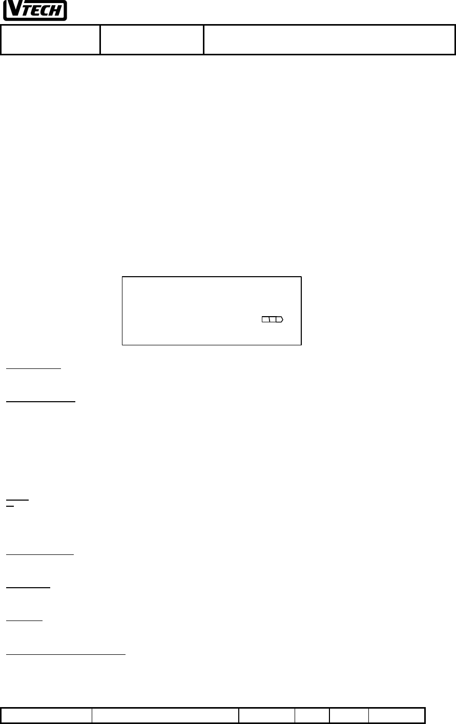
The LCD of the handset is 2*16 dot matrix with some icons. The top two rows are 2*16 dot matrix.
The 3rd and 4th row is icons and 7-segment display. The full LCD is.
2*16 dot matrix
It displays handset ID in standby mode (eg Handset ID is 01).
Handset & CO Line
There are 4 CO lines, 1, 2, 3, and 4
% & CO line OFF: CO Line is idle
% ON & CO line ON: CO Line is in use
% & CO line FLASH: CO Line is held
If the CO line is disconnected, % & CO line is OFF
Ringer
%: Ringer is set to OFF
%FLASH: CO Line is ringing
Press [ss ] / [tt ] in idle mode or ringing mode to adjust the ringer volume
Ringer and Handset
Both ringer and Handset icon FLASH: Transfer ring or recall ring
Battery Icon
This icon represents the battery status
NEW Icon
This icon is for new caller ID messages if there is new caller ID in database in idle mode or in retrieve mode.
Caller Counter Icon (eg 25 in fig.1)
This icon has three purposes.
a) New caller ID counter (NEW icon is on)
It means there are 25 new caller ID in database.
Or
XXXXXXXXXXXXXXXX
XXXXXXXXXXXXXXXX
NEW 25 9/02 11:09 AM
%1% %2% %3% %4 %
VTECH TELECOMMUNICATIONS LTD.
File :VT40-2421
MMI REV 4.doc Date : 15 Nov, 2000 TITLE : INTERNAL PRODUCT SPECIFICATION
DOCUMENT NO. VT40-2421 MMI REV NO. 4 PAGE 12 of 43
b) Total caller ID counter (NEW icon is off)
It means there are totally 25 caller ID in database.
Or
c) Current ringing Co line (eg line 3)
When Co line 3 is ringing, it will display “L3” instead of caller ID counter. The 1st row will display caller name
and the 2nd row will show caller number.
7-segment for date/time (It is for Caller ID only)
7-segment is for date and time. (eg 9/02 11:09 AM )
It means date and time is September 2 and 11:09am respectively.
VTECH TELECOMMUNICATIONS LTD.
File :VT40-2421
MMI REV 4.doc Date : 15 Nov, 2000 TITLE : INTERNAL PRODUCT SPECIFICATION
DOCUMENT NO. VT40-2421 MMI REV NO. 4 PAGE 13 of 43
6. Operations
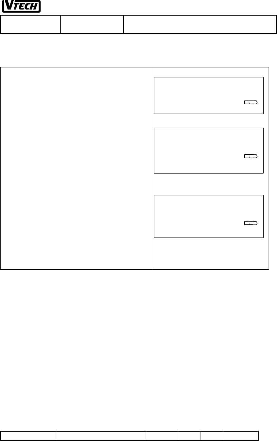
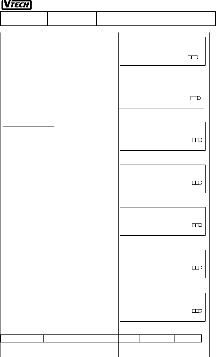
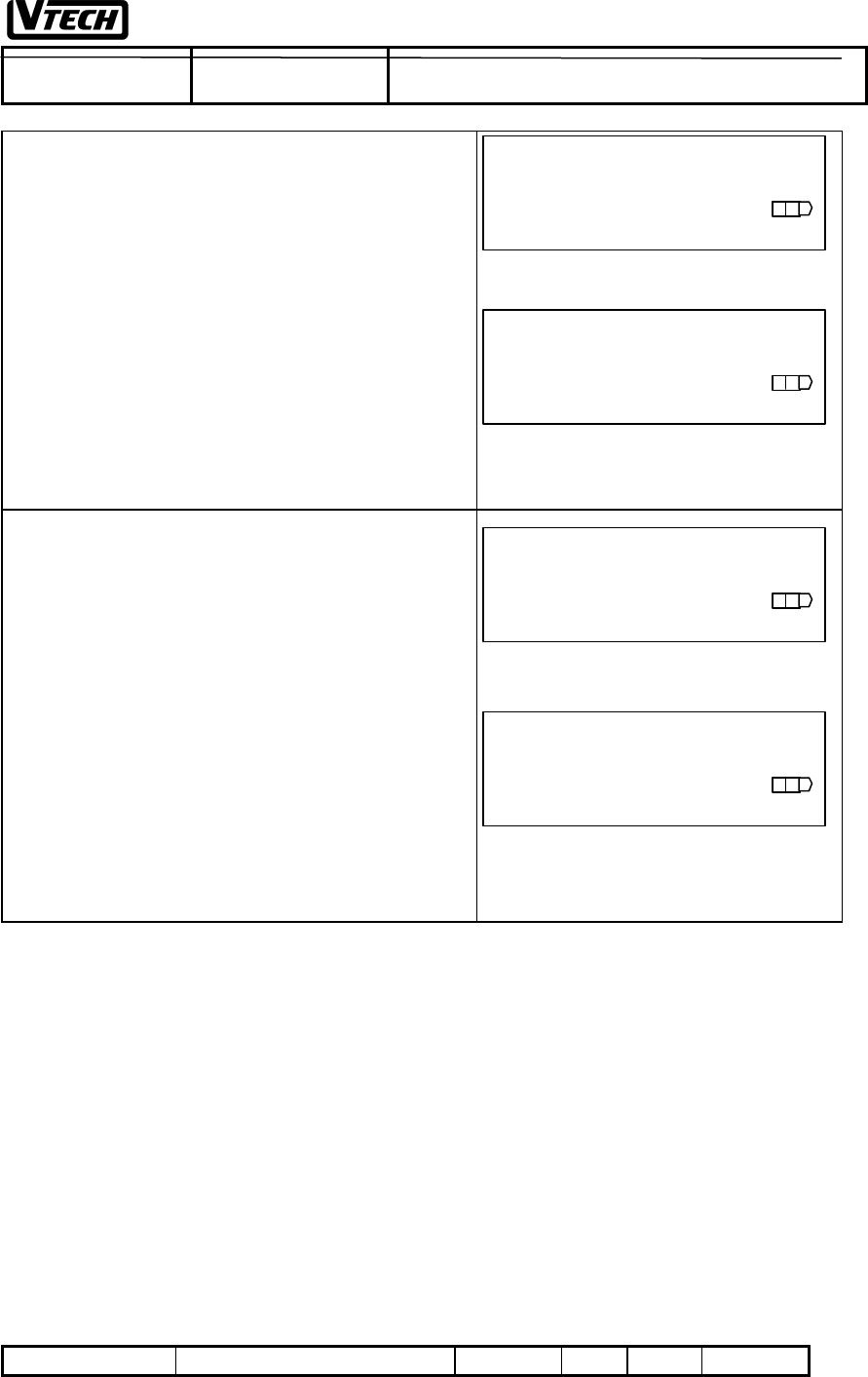
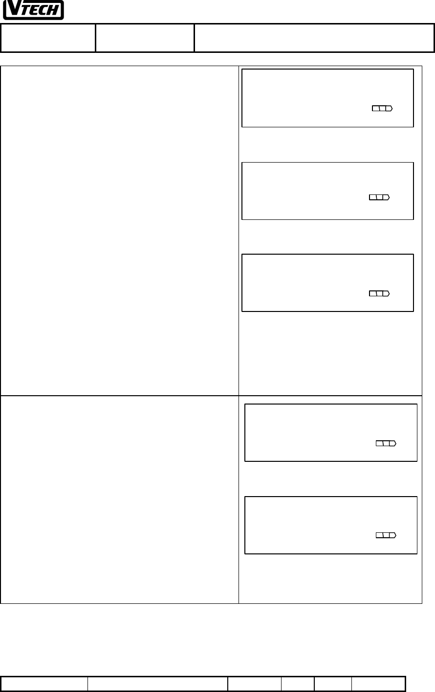
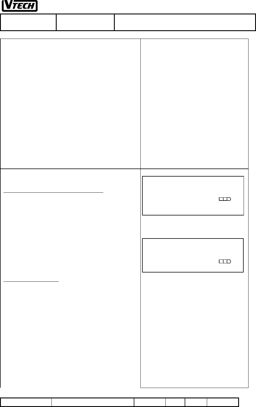
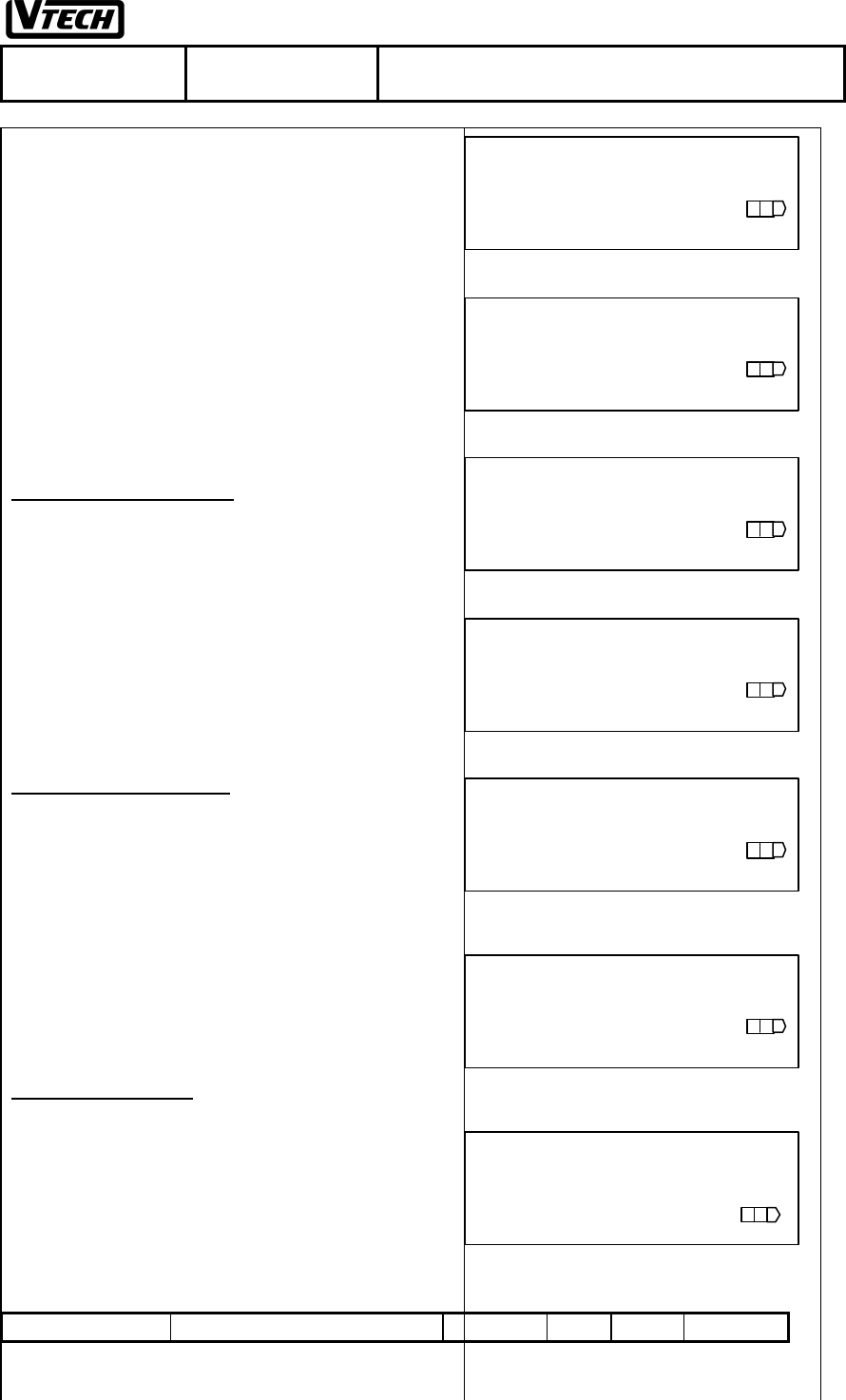
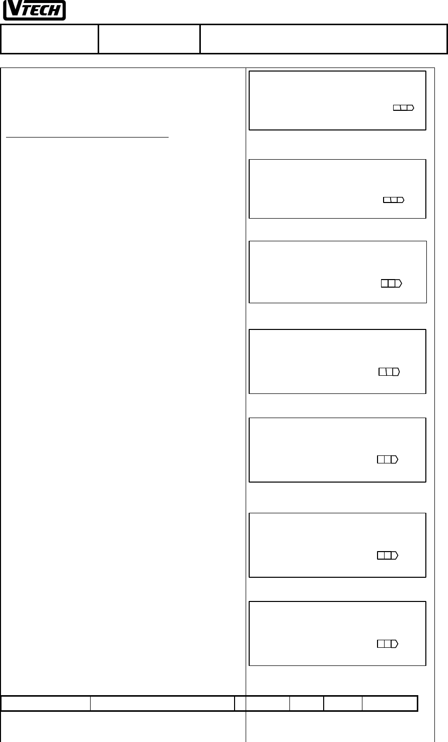
1. STANDBY MODE
1. In the Standby mode and the handset ID is programmed,
the display shows as Fig. 1a or 1b or 1c:
1a) Handset links with the idle base unit
1b) Handset links with the busy base unit
1c) Handset cannot link with base unit
Note: 1. In the No Service case, the handset may have the
wrong S.S.C., or if the local power is OFF at the base unit or
the handset is out of the system service areas.
2. If trying to request a service from the 'Busy' base unit
which all the paths are in use, you will get a audible warning
tone.
HANDSET 01
Fig.1a
HANDSET 01
BUSY
Fig.1b
HANDSET 01
NO SERVICE
Fig.1c
VTECH TELECOMMUNICATIONS LTD.
File :VT40-2421
MMI REV 4.doc Date : 15 Nov, 2000 TITLE : INTERNAL PRODUCT SPECIFICATION
DOCUMENT NO. VT40-2421 MMI REV NO. 4 PAGE 14 of 43
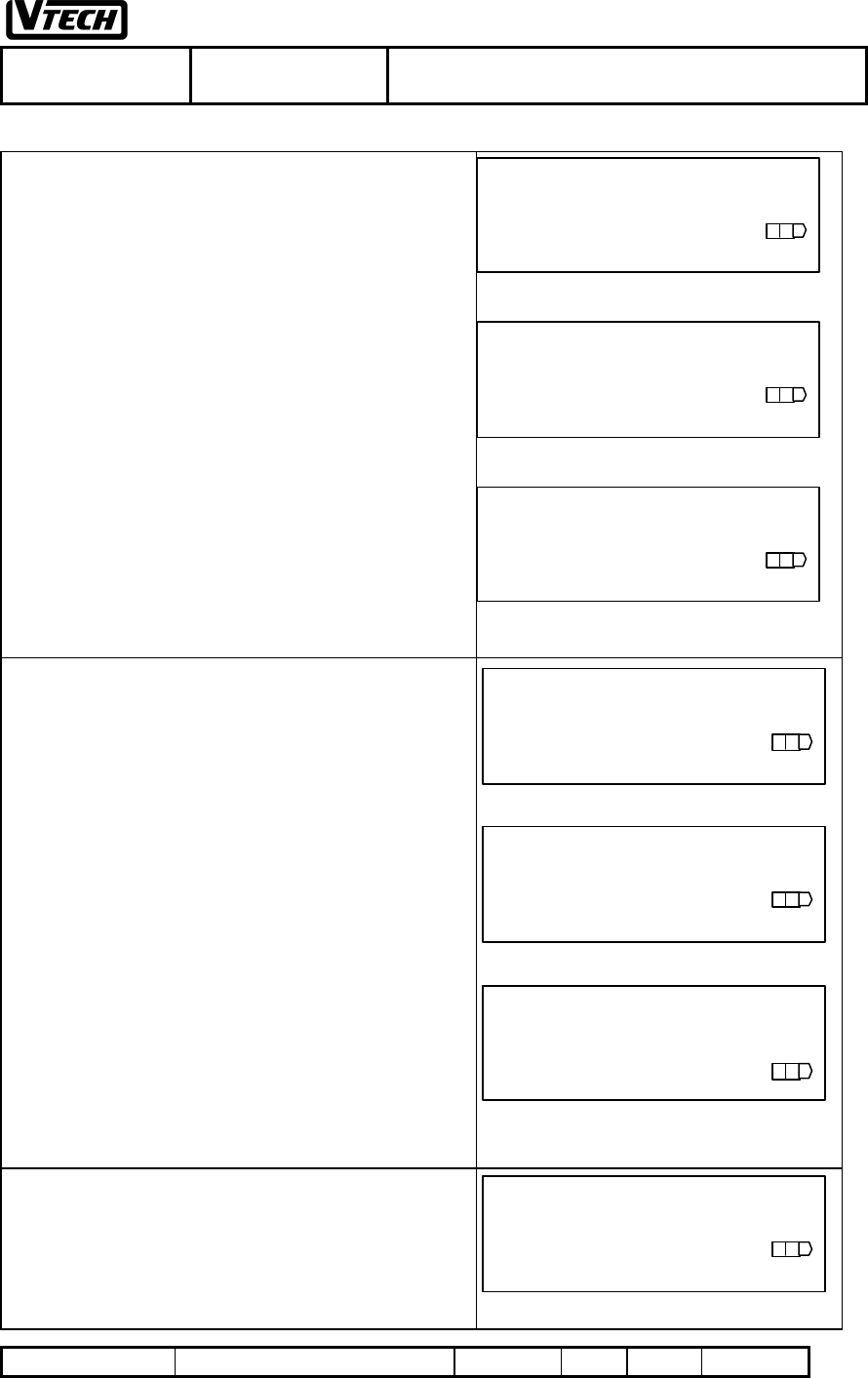
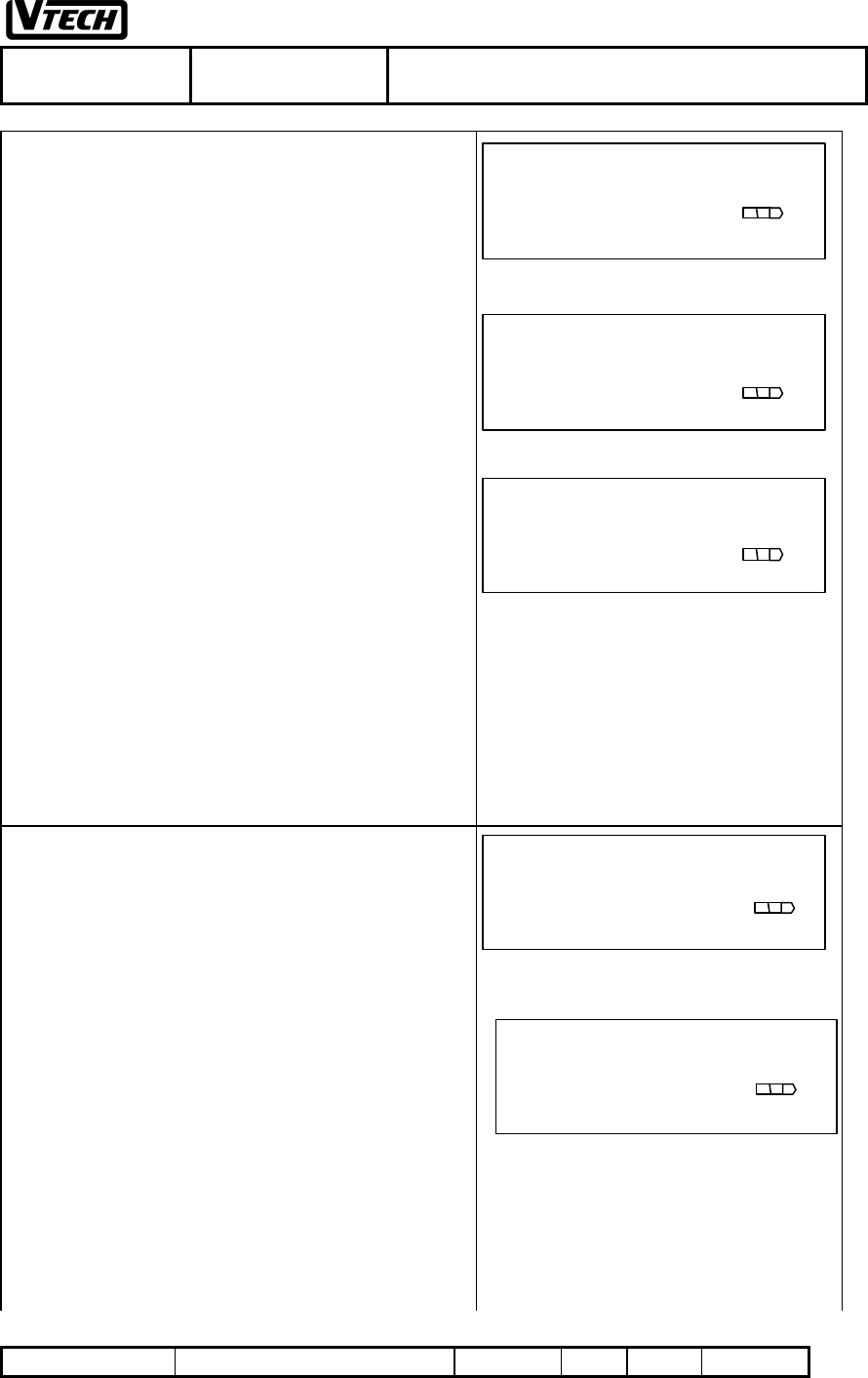
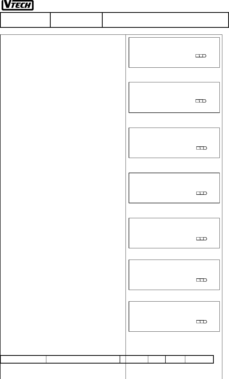
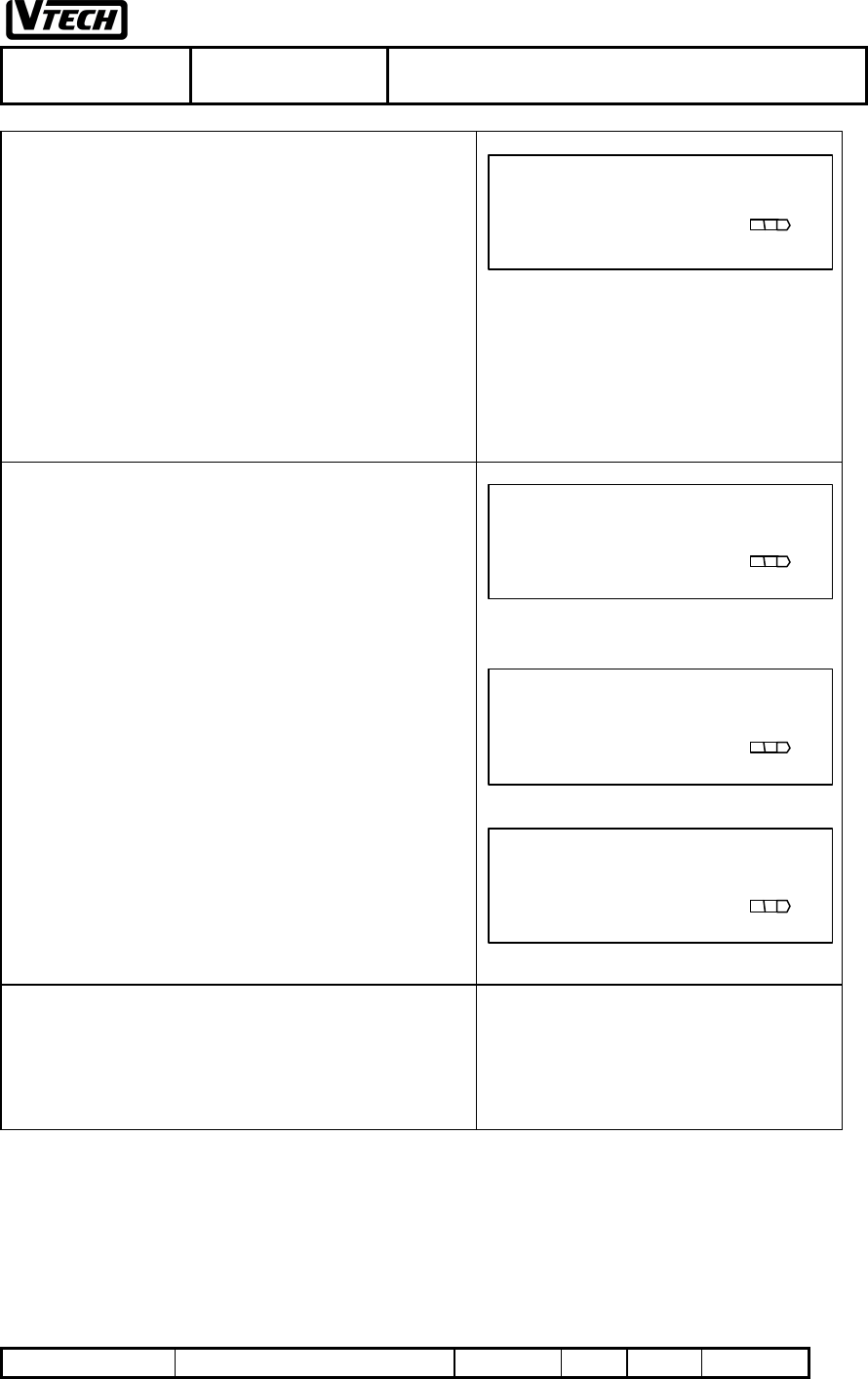
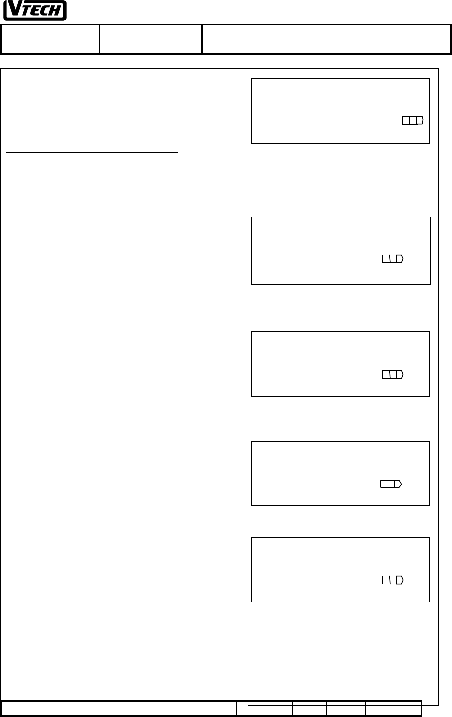
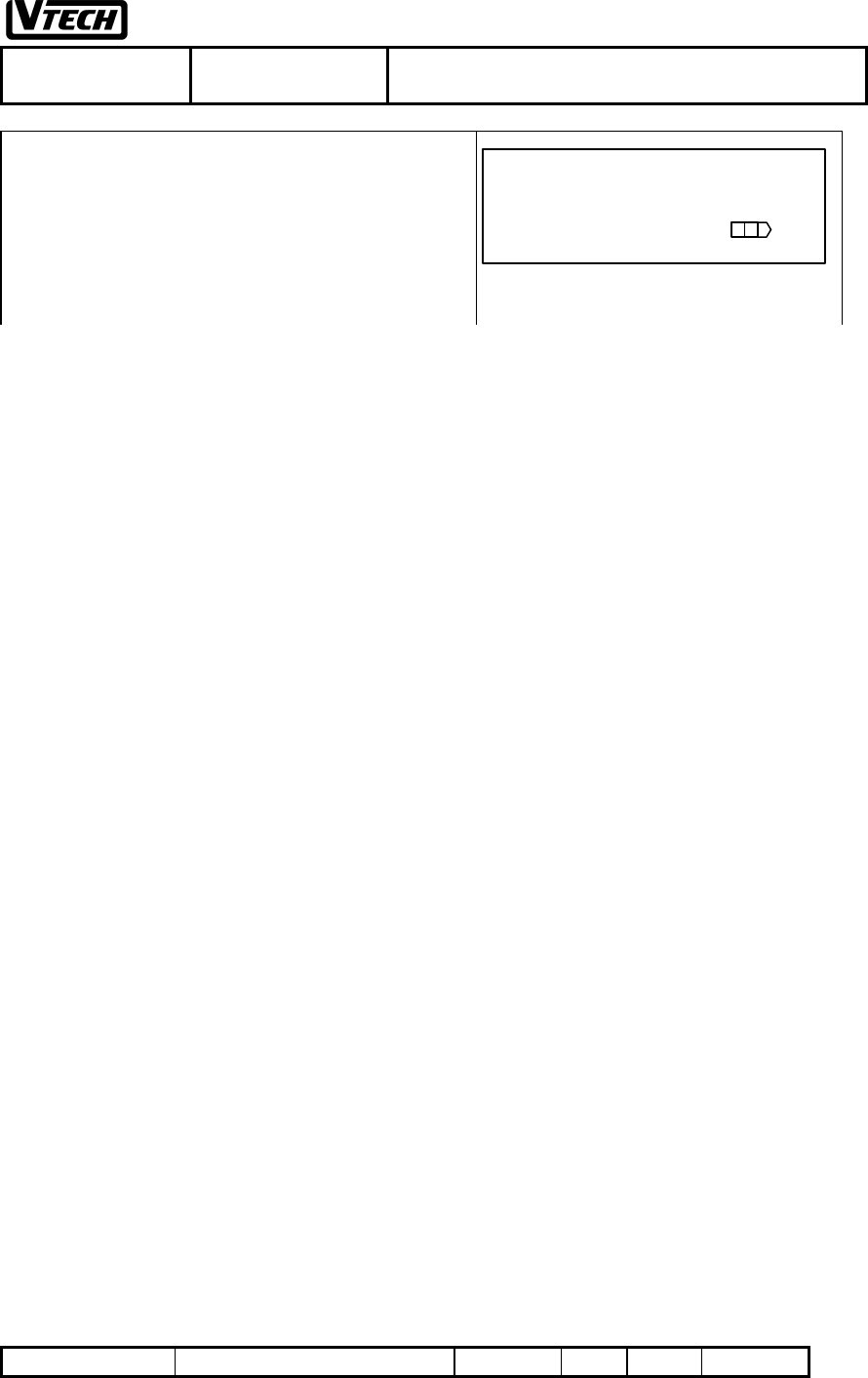
2. INSTALLATION
After charging, the handset is removed it from its charging
cradle, the screen will as Fig. 2.
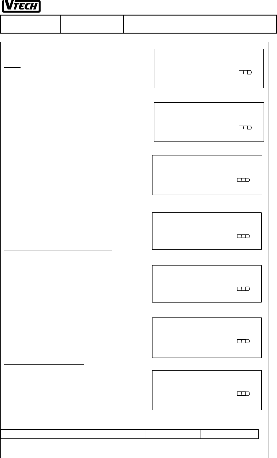
Registering handset security codes
1. Press [MEM] and the LCD will display the first
programming choice as Fig.3
2. Press [ss ] / [tt ] until displaying “HS SECUIRTY
CODE”(refer to Fig 4. Show “XXXXXX” or “EMPTY”)
3. Press [#] to confirm this option
4. Enter 6 digits for the security code (see Fig. 5,
eg.123456).
5. Press [#] to confirm the code and the handset will display
Fig. 7 for 3 seconds if the registration is successful and
return to programming mode (refer to Fig. 4).
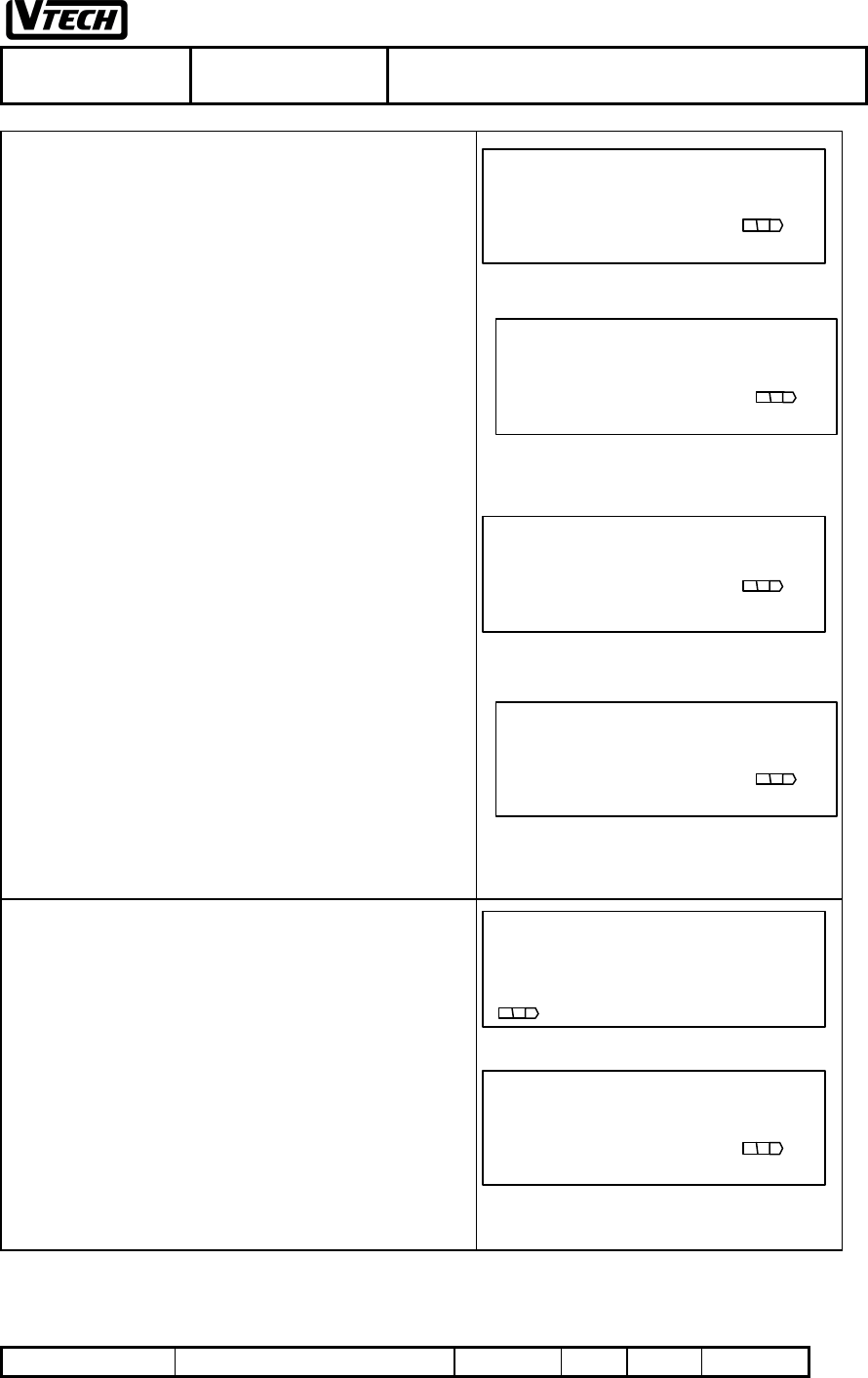
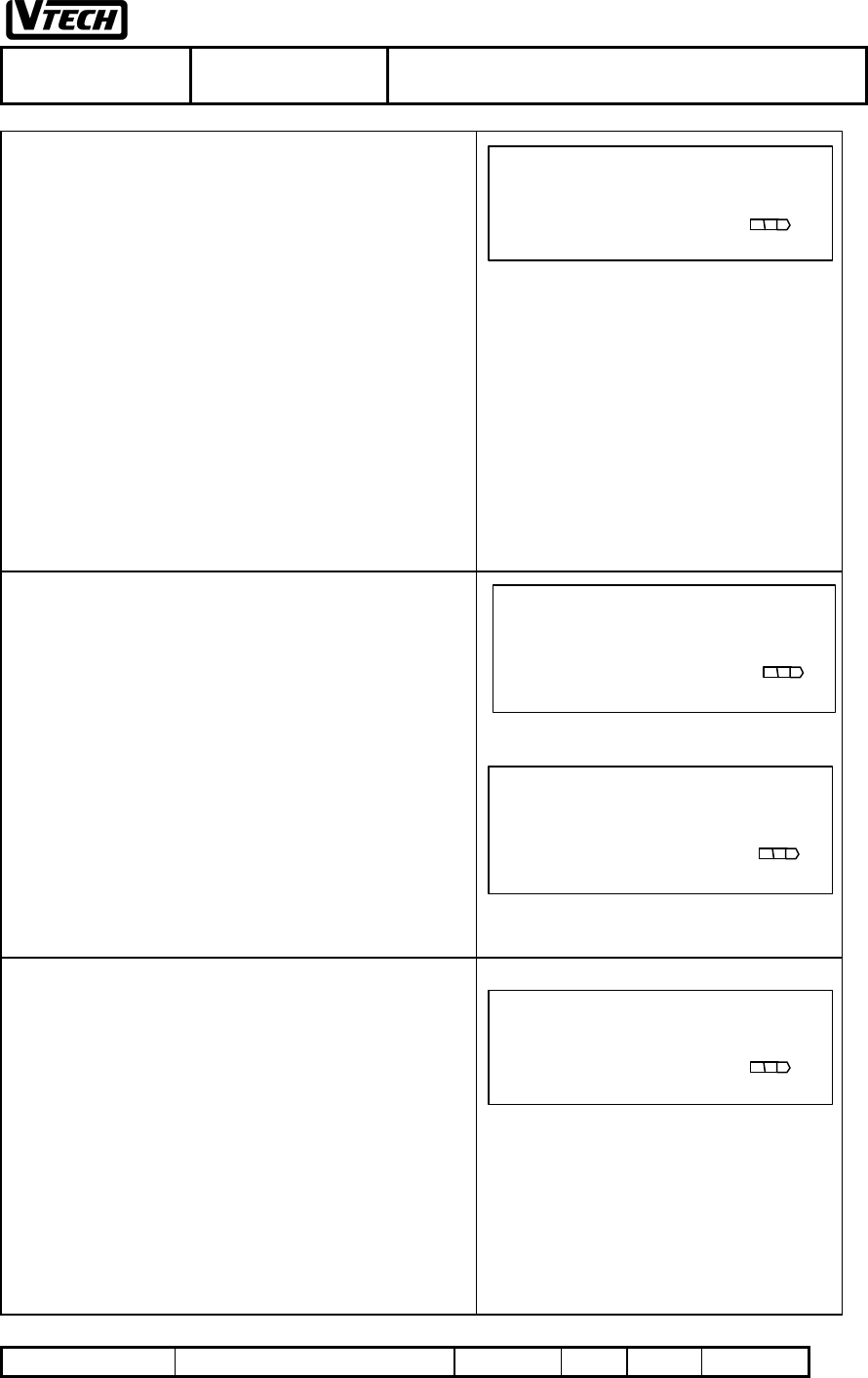
Registering base security codes
1. Power up the base unit and be sure the handset security
code has been programmed to in the handset
2. Press [MEM] t o enter the programming mode (refer to
Fig 3)
3. Press [ss ] / [tt ] until displaying “BU SECUIRTY
CODE”(refer to Fig 6)
4. Press [#] and HOLD the [#] key until a confirmation beep
is heard to indicate the security code is accepted correctly
in the base unit.
5. The handset will display Fig. 7 for 3 seconds if the
registration is successful and return to programming
mode (refer to Fig. 6).
6. After about 15 seconds, if you still do not get the
confirmation, then it means that the programming failed.
The error message is displayed as Fig 8 for 3 seconds and
return to Fig.6 display. In this case, the user has to re-do
from step 1 again.
Note:
If the programming is successful, a happy tone (one beep)
will be emitted.
If the programming is unsuccessful, an error tone(two beeps)
will be emitted.
Fig.2
HANDSET 01
NO SERVICE
Fig.3
MEMORY
[ss ] /[ tt ]
Fig.6
BU SECURITY CODE
[ss ] /[ tt ]
Fig.4
HS SECURITY CODE
XXXXXX [ss ] /[ tt ]
Fig.5
PLS ENTER CODE
123456
Fig.7
PROGRAMMING
SUCCESSFUL!
Fig.8
ERROR! PLS
REGISTER AGAIN!
VTECH TELECOMMUNICATIONS LTD.
File :VT40-2421
MMI REV 4.doc Date : 15 Nov, 2000 TITLE : INTERNAL PRODUCT SPECIFICATION
DOCUMENT NO. VT40-2421 MMI REV NO. 4 PAGE 15 of 43
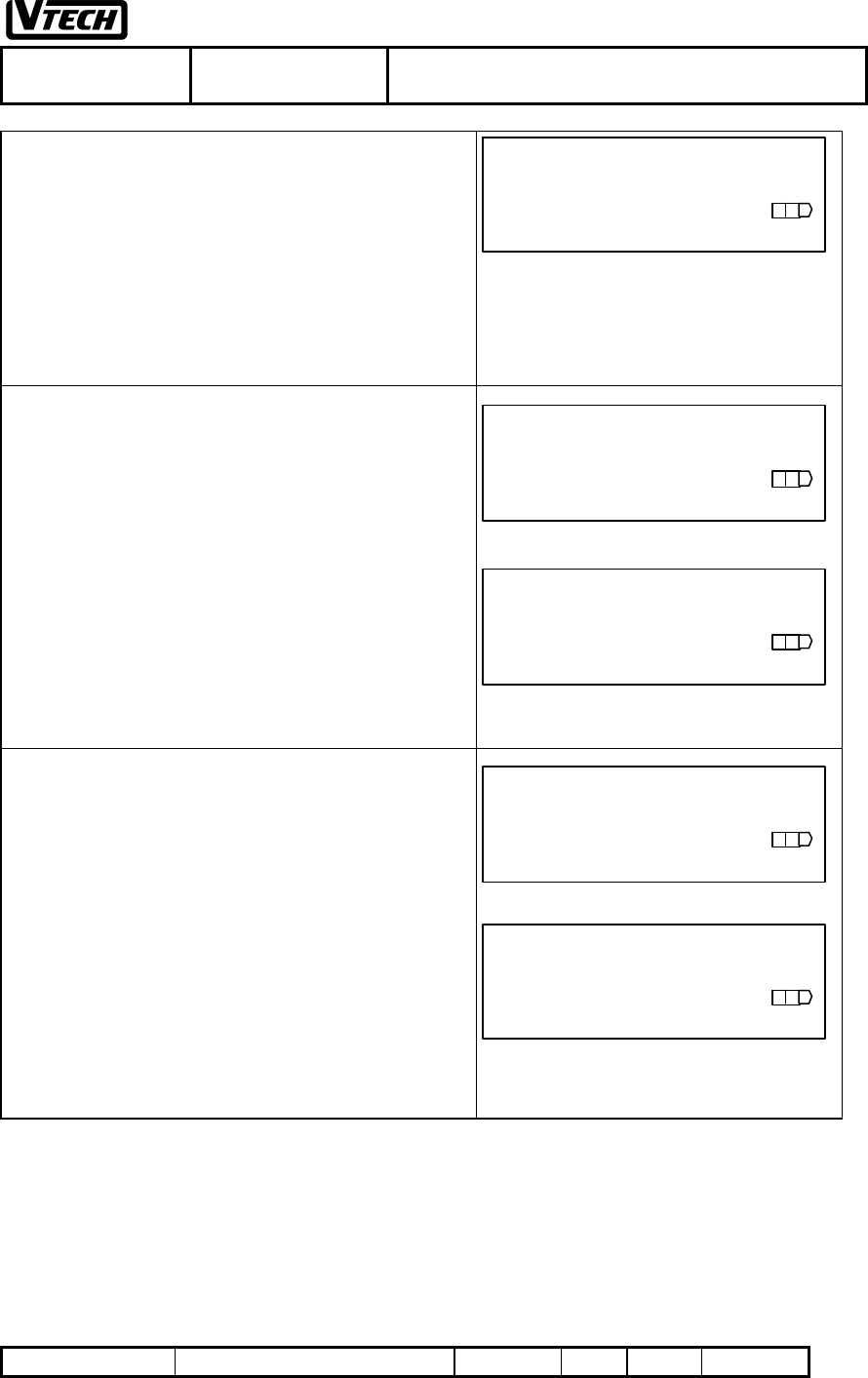
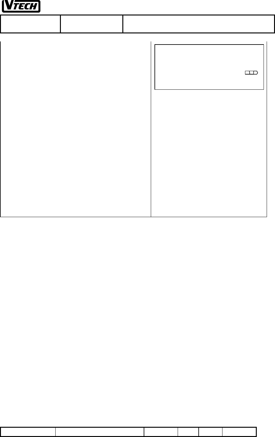
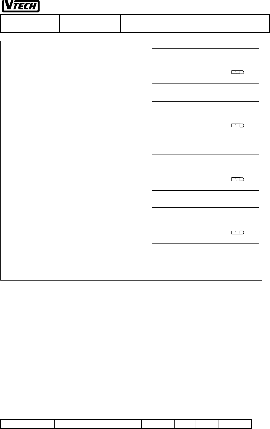
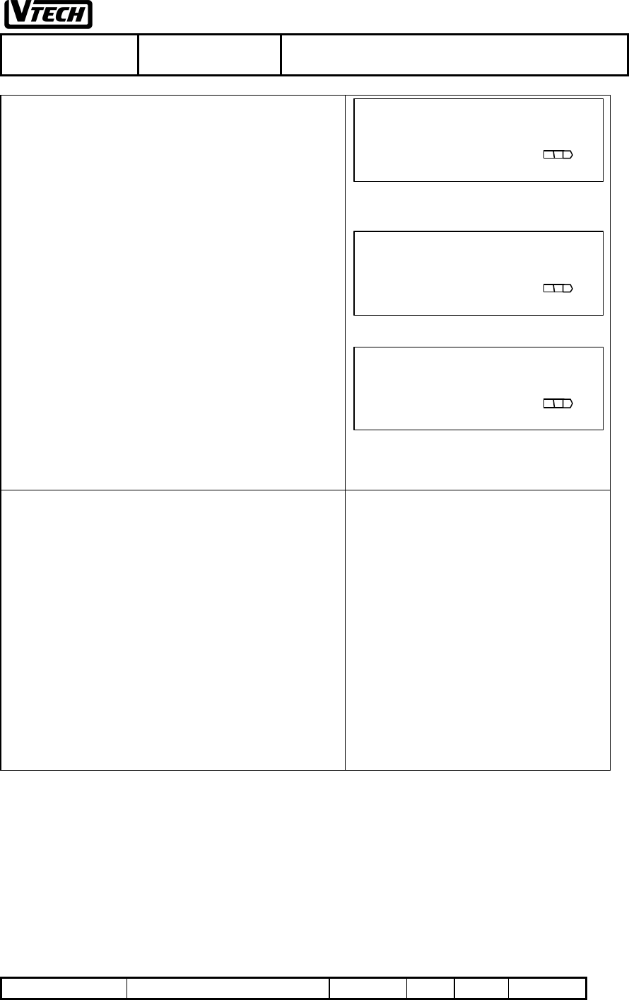
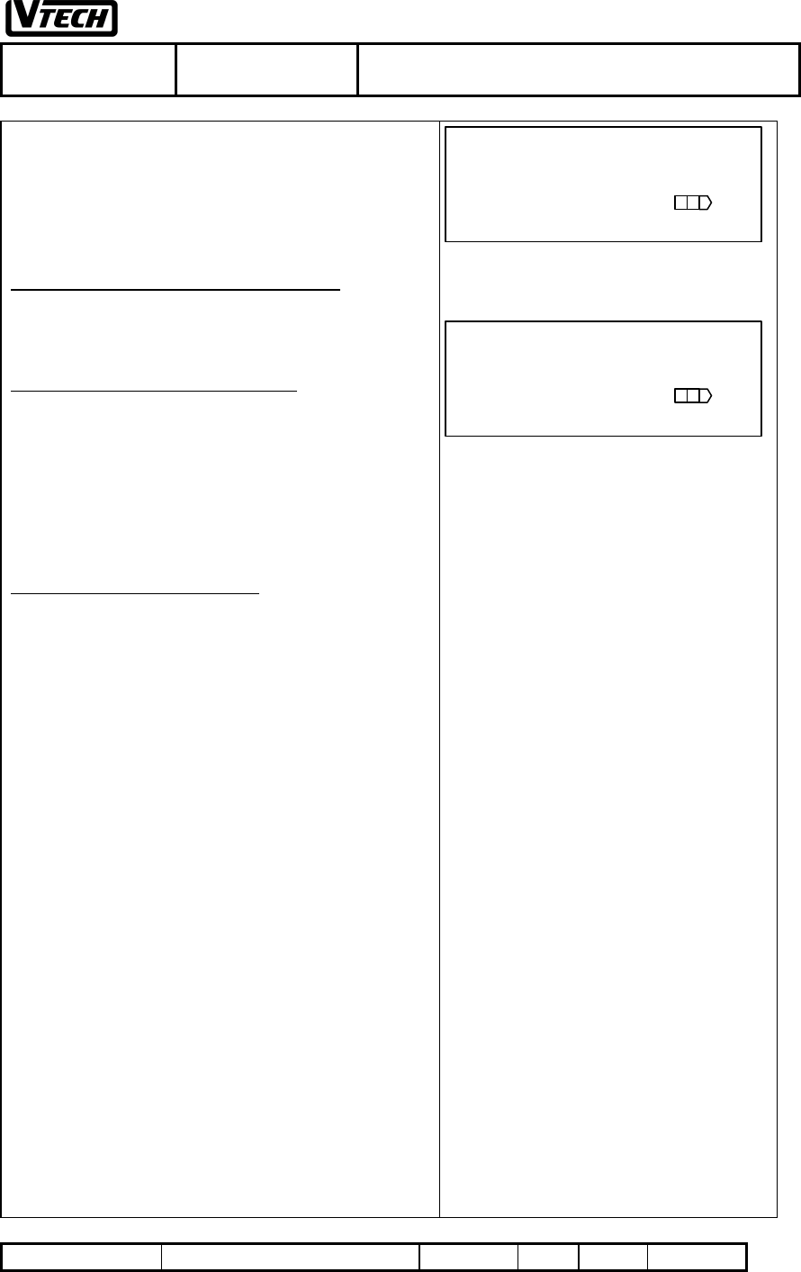
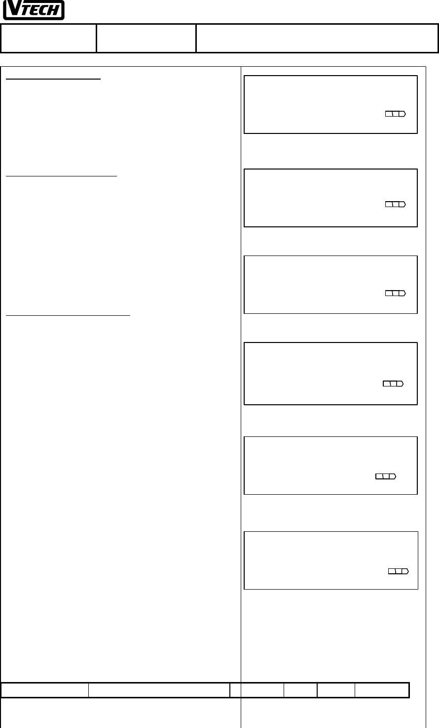
3. PROGRAMMING HANDSET ID
1. Press [MEM] to enter the programming mode (refer to
Fig. 3)
2. Press [ss ] / [tt ] until displaying “HANDSET ID”(refer
to Fig. 9)
3. Press [#] to confirm this option (refer Fig. 9)
4. Enter 2 digit ID no. (01-12) (refer to Fig.10). For
example, handset ID is 05
5. Press [#] to confirm the ID no. and the screen will display
Fig. 11 for 3 seconds and return to programming display
as Fig. 9 (The ID will be changed to 05)
4. SETTING RINGER VOLUME & ON/OFF
1. Press [MEM] to enter the programming mode (refer to
Fig 3)
2. Press [ss ] / [tt ] until displaying “CO LINE x RING”
where x=1-4 of your chosen line for setting ringer on/off.
(refer to Fig. 12)
3. Press [#] to confirm this option
4. Press [ss ] / [tt ] to choose ON or Off
5. Press [#] to confirm the choice to display either Fig.13 or
Fig.14 and the screen will display Fig. 11 for 3 seconds
and return to programming display as Fig 12.
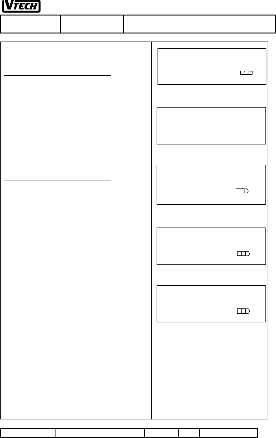
5. PROGRAMMING RINGER TYPE (4
TYPES)
1. Press [MEM] to enter the programming mode (refer to
Fig 3)
2. Press [ss ] / [tt ] until displaying “RINGER TYPE” (refer
to Fig. 15 )
Fig.9
HANDSET ID
01 [ss ] /[ tt ]
Fig.10
PLS ENTER ID NO.
05
Fig.11
PROGRAMMING
SUCCESSFUL!
Fig.12
CO LINE 1 RING
ON [ss ] /[ tt ]
Fig.13
CO LINE 1 RING
ON [ss ] /[ tt ]
Fig.14
CO LINE 1 RING
OFF [ss ] /[ tt ]
Fig.15
RINGER TYPE
3 [ss ] /[ tt ]
VTECH TELECOMMUNICATIONS LTD.
File :VT40-2421
MMI REV 4.doc Date : 15 Nov, 2000 TITLE : INTERNAL PRODUCT SPECIFICATION
DOCUMENT NO. VT40-2421 MMI REV NO. 4 PAGE 16 of 43
3. Press [#] to confirm this option.
4. Choose the ringer type by using [ss ] / [tt ] (refer to
Fig.16). The default type is 1.
5. Press [#] to confirm the choice and the screen will
display Fig. 11 for 3 seconds and return to the
programming display as Fig 15 (Change to type 3)
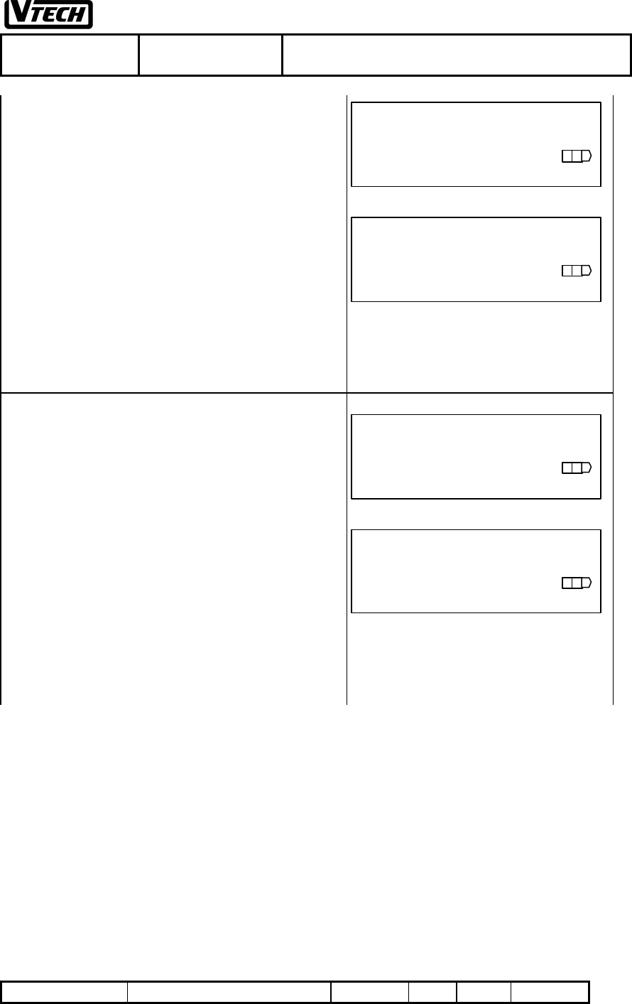
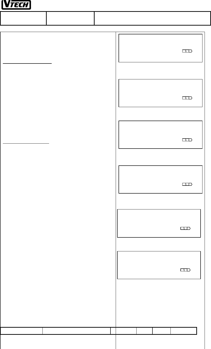
6. PROGRAMMING FLASH TIME
1. Press [MEM] to enter the programming mode (refer to
Fig 3)
2. Press [ss ] / [tt ] until displaying “FLASH TIME” (refer
to Fig.17)
3. Press [#] to confirm this option.
4. Choose the flash time by using [ss ] / [tt ] (refer to
Fig.18). (Option is from 100ms to 900ms)
5. Press [#] to confirm the choice and the screen will
display Fig. 11 for 3 seconds and return to the
programming display as Fig 17. (Change to 300ms)
7. PROGRAMMING TONE/PULSE MODE
1. Press [MEM] to enter the programming mode (refer to
Fig. 3)
2. Press [s] / [t] until displaying “TONE/PULSE” (refer
to Fig..19)
3. Press [#] to confirm this option.
4. Select Tone or Pulse by using [s] / [t] (refer to Fig. 20)
5. Press [#] to confirm the choice and the screen will
display Fig. 11 for 3 seconds and return to the
programming display as Fig. 19. (Change to TONE)
Fig.16
RINGER TYPE
1 [ss ] /[ tt ]
Fig.17
FLASH TIME
100ms [ss ] /[ tt ]
Fig.18
FLASH TIME
300ms [ss ] /[ tt ]
Fig.19
TONE/PULSE
PULSE [ss ] /[ tt ]
Fig.20
TONE/PULSE
TONE [ss ] /[ tt ]
VTECH TELECOMMUNICATIONS LTD.
File :VT40-2421
MMI REV 4.doc Date : 15 Nov, 2000 TITLE : INTERNAL PRODUCT SPECIFICATION
DOCUMENT NO. VT40-2421 MMI REV NO. 4 PAGE 17 of 43
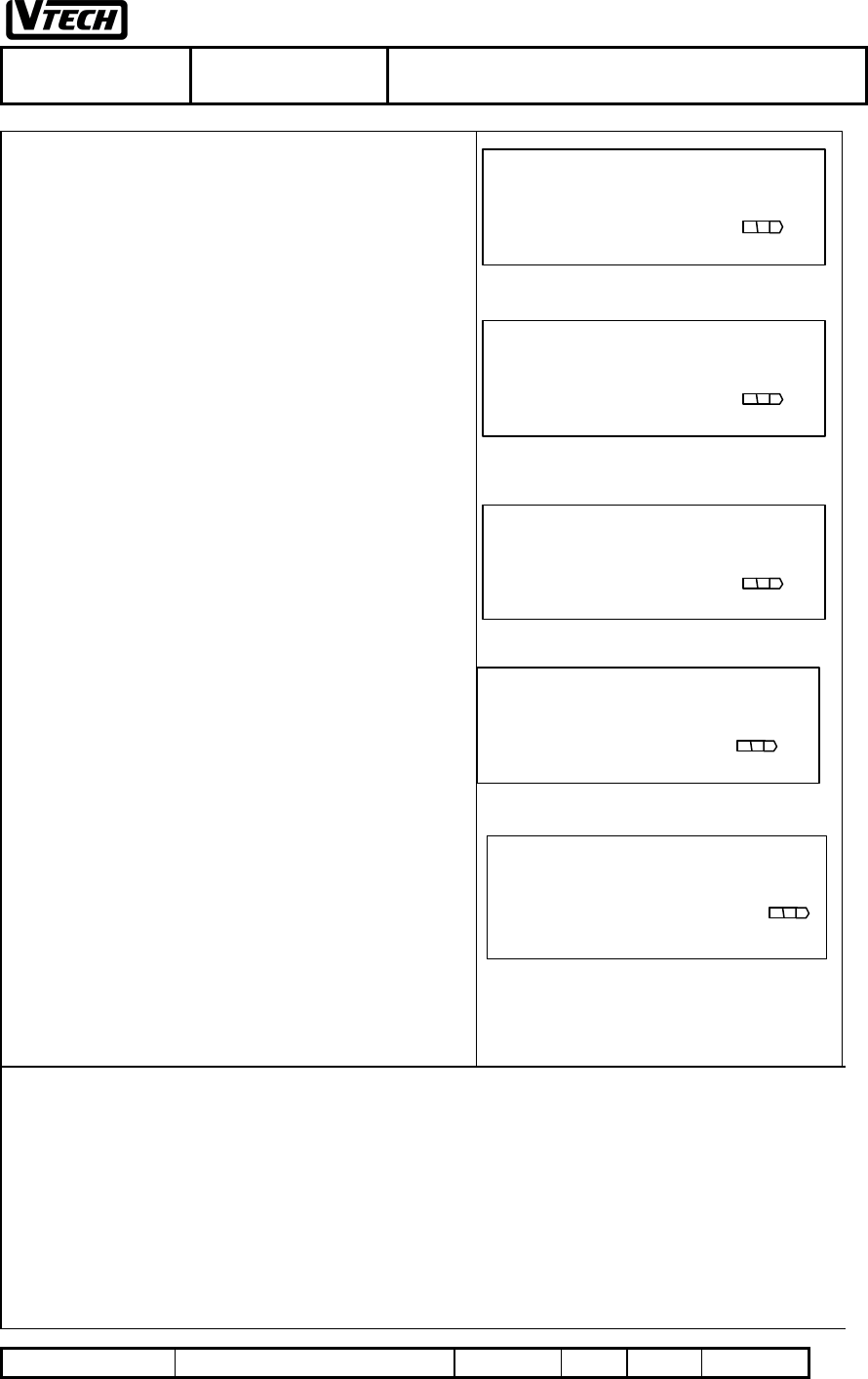
8. PROGRAMMING HOLD REMINDER TIME
1. Press [MEM] to enter the programming mode (refer to
Fig 3)
2. Press [s] / [t] until displaying “HOLD REMINDER”
(refer to Fig.21)
3. Press [#] to confirm this option.
4. Choose the reminder time setting by using [s] / [t]
(refer to Fig. 22) (Option:OFF/15/30/45/60 seconds and
the default is 30 seconds)
5. Press [#] to confirm the choice and the screen will
display Fig. 11 for 3 seconds and return to the
programming display as Fig 21. (Change to 45 SEC)
9. PROGRAMMING LINE IN USE DETECT
1. Press [MEM] to enter the programming mode (refer to
Fig 3)
2. Press [s] / [t] until displaying “LINE IN USE” (refer
to Fig.23)
3. Press [#] to confirm this option.
4. Choose the line in use on or off by using [s] / [t] (refer
to Fig.. 24) (The default is on)
5. Press [#] to confirm the choice and the screen will
display Fig. 11 for 3 seconds and return to the
programming display as Fig 23. (Change to OFF)
Fig.21
HOLD REMINDER
30SEC [ss ] /[ tt ]
Fig.22
HOLD REMINDER
45SEC [ss ] /[ tt ]
Fig.23
LINE IN USE
ON [ss ] /[ tt ]
Fig.24
LINE IN USE
OFF [ss ] /[ tt ]
VTECH TELECOMMUNICATIONS LTD.
File :VT40-2421
MMI REV 4.doc Date : 15 Nov, 2000 TITLE : INTERNAL PRODUCT SPECIFICATION
DOCUMENT NO. VT40-2421 MMI REV NO. 4 PAGE 18 of 43
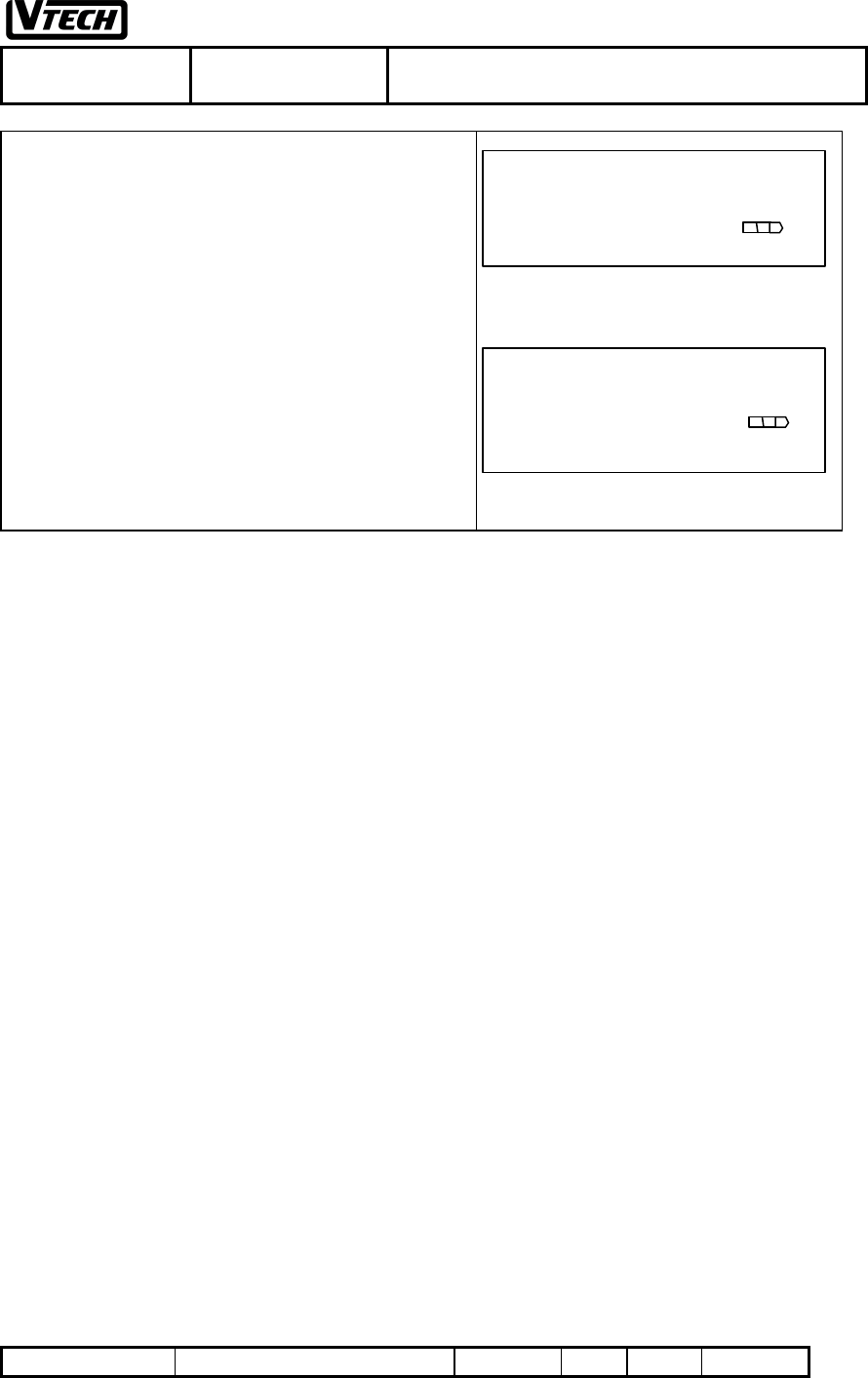
10. RESET HANDSET PROGRAMMING
1. Press [MEM] to enter the programming mode (refer to
Fig 3)
2. Press [s] / [t] until displaying “HANDSET RESET”
(refer to Fig.25)
3. Press [#] to confirm this option and the LCD will display
Fig 26
4. Press [#] to confirm the choice and the screen will
display Fig. 11 for 3 seconds and return to the
programming display as Fig 1a or 1b or 1c.
11. RESET BASE PROGRAMMING
1. Re-power the unit
2. Press [MEM] to enter the programming mode (refer to
Fig. 3)
3. Press [s] / [t] until displaying “BASE RESET” (refer
to Fig.27)
4. Press [#] to confirm this option and the LCD will display
Fig. 28
5. Press [#] to confirm the choice and the screen will
display Fig. 11 for 3 seconds and return to the
programming display as Fig 1a or 1b or 1c.
Fig.25
3
HANDSET RESET
[ss ] /[ tt ]
Fig.26
4
RESET YES
Fig.28
RESET YES
Fig.27
BASE RESET
[ss ] /[ tt ]
VTECH TELECOMMUNICATIONS LTD.
File :VT40-2421
MMI REV 4.doc Date : 15 Nov, 2000 TITLE : INTERNAL PRODUCT SPECIFICATION
DOCUMENT NO. VT40-2421 MMI REV NO. 4 PAGE 19 of 43
12. MAKING OUTSIDE LINE CALL
If trying to request a service from the 'busy' base unit which
all the paths are in use. You will get an audible warning tone.
1. Press an available [Lx], where x = 1/2/3/4. For example,
press [L2]. The LCD will display Fig. 29
2. For example, the telephone number is
035775141+PAUSE +2581"
3. Enter "035775141and then press [FUNCTION][7], then
the LCD will display Fig. 30
4. Then, enter "2581" & the LCD will display Fig. 31.
Some leading digits will be shifted away.
5. Press [END] to release the call, or put the handset to the
charger to release the call automatically. The screen will
return to idle mode as Fig.1a
13. ANSWERING CALL
You may press any one of the digit keys
[1/2/3/4/5/6/7/8/9/0/*/#] to pick up the ringing call, and the
answer priority is Ringing Intercom Call, Transfer Calls, Hold
Recall Calls, Ringing CO Line Calls. But, you may override
the priority, by press the [Lx] or [ICM] directly.
1. Handset in the standby mode when the handset rings (eg.
Co line 2), the caller ID will be displayed. (refer to
Fig.32)
2. Press [any one of the digit] key, or you may press the
ringing [Lx] to pick up the CO ringing line, the LCD will
display as Fig. 33.
3. Press [END] to release the call, or put the handset to the
charger to release the call automatically. The screen will
return to idle mode as Fig.1a
LINE 2 mm:ss
%2
Fig.29
LINE 2 mm:ss
035775141P
%2
Fig.30
LINE 2 mm:ss
035775141P2581
%2
Fig.31
0
TONY KENT
12345678901
L2 9/02 11:09 AM
%
Fig.32
LINE 2 mm:ss
%2
Fig.33
VTECH TELECOMMUNICATIONS LTD.
File :VT40-2421
MMI REV 4.doc Date : 15 Nov, 2000 TITLE : INTERNAL PRODUCT SPECIFICATION
DOCUMENT NO. VT40-2421 MMI REV NO. 4 PAGE 20 of 43
14. PR-DIALING
1. Enter the telephone number, for example:
"0357751412581 and the LCD will display Fig. 34
2. Press an available [Lx], where x = 1/2/3/4. For example,
press [L2]. The LCD will display Fig. 35
3. Press [END] to release the call, or put the handset to the
charger to release the call automatically. The screen will
return to idle mode as Fig.1a
15. REDIAL
1. Standby, press an available [Lx], where x = 1/2/3/4. For
example, if you press [L2], the LCD will display Fig 36.
2. Press [REDIAL] to redial the last dialed number. The
LCD will display as Fig .37.
16. REDIAL WITH PRE-DAILING
1. Press [REDIAL] to redial the last dialed number. The
LCD will display as Fig .38
2. After Last dialing number reviewed, and you want to dial
the number. Press an available [Lx], where x = 1/2/3/4,
handset will pick up the CO line and dial out the number
as display as Fig. 39
0357751412581
Fig.34
LINE 2 mm:ss
0357751412581
%2
Fig.35
LINE 2 mm:ss
%2
Fig.36
LINE 2 mm:ss
0357751412581
%2
Fig.37
REDIAL
0357751412581
Fig.38
LINE 2 mm:ss
0357751412581
%2
Fig.39
VTECH TELECOMMUNICATIONS LTD.
File :VT40-2421
MMI REV 4.doc Date : 15 Nov, 2000 TITLE : INTERNAL PRODUCT SPECIFICATION
DOCUMENT NO. VT40-2421 MMI REV NO. 4 PAGE 21 of 43
17. HOLD
1. On line (eg. Line 2), the screen will display either Fig. 33
or Fig.35
2. Press [HOLD], and the LCD will display Fig.40 and
Handset icons will be flashing.
3. After 10 seconds time out, the display will return to idle
display as Fig. 1a with flashing Handset icons
4. If the Hold Reminder Time is not disabled, when you
held a CO line over a programmed period of time, a triple
beep will be heard to remind you that the line is still held.
(The hold reminder time can be set from 15/30/45/60
seconds and off. The default is 30 seconds)
5. If the held CO line is not picked up for 3 minutes, all
handset units will start ringing (i.e., Recall Ring) to
remind all of users. The related icons will be changed.
6. Press [any one of the digit] key or you may press the
ringing [Lx] to pick up the CO hold recall ringing line,
the LCD will display Fig.33
Note: In this wireless system, the held CO line will be
released when the held line isn’t picked up within 5 minutes.
TRANSFER TO/HOLD
%2
Fig.40
VTECH TELECOMMUNICATIONS LTD.
File :VT40-2421
MMI REV 4.doc Date : 15 Nov, 2000 TITLE : INTERNAL PRODUCT SPECIFICATION
DOCUMENT NO. VT40-2421 MMI REV NO. 4 PAGE 22 of 43
MAKE AN INTERCOM CALL
1. Standby, press the [ICM] key. The LCD will display Fig.
42
2. Dial desired intercom number, say station 12 calls station
05, the LCD will display Fig. 43
3. If the Called Party is Idle and Access-able, the calling
party station 12 will display Fig. 44 and the called party
station 05 will get an intercom ring and display Fig.45
4. If the called party is busy and access-able, the calling
party station 12 will display Fig.46
5. If the Called Party is in DND (Ringer Off) Mode and
Access-able, the calling party station 12 will display
Fig.47.
6. If the called party is an illegal number, the calling party
station will display Fig.48.
Note:
-Access-able means the called party is linked with the base
unit.
When the called party is busy or in DND, the called party
station 05 will remain UN-changed. The called party will not
hear a call waiting triple beep for intercom call.
- Illegal means the called party is non-existing or loses the
link with this system.
INTERCOM TO
Fig.42
INTERCOM TO 05
Fig.43
INTERCOM TO 05
RINGING!
Fig.44
INTERCOM BY 12
RINGING!
Fig.45
INTERCOM TO 05
BUSY!
Fig.46
INTERCOM TO 05
DO NOT DISTURB!
Fig.47
INTERCOM TO 05
NOT FOUND!
Fig.48
VTECH TELECOMMUNICATIONS LTD.
File :VT40-2421
MMI REV 4.doc Date : 15 Nov, 2000 TITLE : INTERNAL PRODUCT SPECIFICATION
DOCUMENT NO. VT40-2421 MMI REV NO. 4 PAGE 23 of 43
18. ANSWERING AN INTERCOM CALL
1. Handset is ringing, the LCD will display Fig. 45
2. Press [any one of the digit] key or you may press the
[ICM] to pick up the ringing intercom call. The LCD will
display Fig. 49.
3. The calling party station will show Fig.50
.
19. PAGE CALL TO THE HANDSET
1. Make an intercom call. The calling party station will
display Fig.44
2. The called party station 05 will get an intercom ring and
display Fig.45
3. When the calling party station 12 presses the [ICM] key
again, the intercom ring will be changed to talk
automatically. The calling party station 12 display Fig.
51, while the called party’s LCD will display Fig. 52.
4. If the called party station 05 wants to talk by handset, just
press [SPEAKERPHONE] and the LCD will display Fig.
49.
INTERCOM BY 12
TALKING!
Fig.49
INTERCOM TO 05
TALKING!
Fig.51
INTERCOM TO 05
TALKING!
Fig.50
INTERCOM BY 12
SPEAKERPHONE!
Fig.52
VTECH TELECOMMUNICATIONS LTD.
File :VT40-2421
MMI REV 4.doc Date : 15 Nov, 2000 TITLE : INTERNAL PRODUCT SPECIFICATION
DOCUMENT NO. VT40-2421 MMI REV NO. 4 PAGE 24 of 43
20. INTERCOM CALL AND PAGE CALL
INTERCHANGING
1. After make a page call. The calling party station 12 will
display Fig. 51
2. The called party station 05 will stop ring and display
Fig.52
3. The calling party station 12 presses the [ICM] key again.
The page will be changed to intercom ring automatically.
The calling party station 12 will display Fig.44
4. The called party station 05 will get an intercom ring and
display Fig.45
Note:
1. If the called party answers the call by pressing the [ICM] or
[SPEAKERPHONE] key, the intercom call will not change to
“Page Call” mode anymore.
VTECH TELECOMMUNICATIONS LTD.
File :VT40-2421
MMI REV 4.doc Date : 15 Nov, 2000 TITLE : INTERNAL PRODUCT SPECIFICATION
DOCUMENT NO. VT40-2421 MMI REV NO. 4 PAGE 25 of 43
21. CONFERENCE CALL
The user is allowed to make a three-way conference call.
Two CO lines Conference Call
1. On CO line, the LCD will display Fig.53 or Fig.54
2. Press [HOLD], the LCD will display Fig. 55. Handset
icons will be flashing.
3. Make the second CO line call, the LCD will display Fig.
56
4. Press [FUNCTION] and LCD will display Fig. 57. The
first line’s icon will be flashing.
5. Press [CONF] (same as [*]) to bridge the two CO lines
and the LCD will display Fig.58a or Fig.58b if in
speakerphone mode
One CO line Conference Call
1. On CO line, the LCD will display Fig.53 or Fig.54
2. Press [HOLD], the LCD will display Fig. 55
3. Make an intercom call to another station (eg.05) and it is
available. The calling party will display Fig. 50 and the
called party will display Fig.49.
4. Press [FUNCTION]and LCD will display Fig. 57
5. Press [CONF] (same as [*]) to bridge the two handsets
and one CO lines, the LCD will display Fig.59a or
Fig.59b if in speakerphone mode
(Note: The dialing number field should be blank.)
LINE 2 mm:ss
%2
Fig.53
LINE 2 mm:ss
0357751412581
%2
Fig.54
TRANSFER TO/HOLD
%2
Fig.55
LINE 3 mm:ss
0357751412555
%2 %3
Fig.56
L2+L3 mm:ss
0357751412555
%2 %3
Fig.58a
a
[1] DEL [4]DND
[7] PAUSE [*] CONF
%2 %3
Fig.57
VTECH TELECOMMUNICATIONS LTD.
File :VT40-2421
MMI REV 4.doc Date : 15 Nov, 2000 TITLE : INTERNAL PRODUCT SPECIFICATION
DOCUMENT NO. VT40-2421 MMI REV NO. 4 PAGE 26 of 43
22. TRANSFERRING CO CALL
1. On CO line, the LCD will display Fig.53 or Fig.54
2. Press [HOLD], the LCD will display Fig. 55
3. After the 10 seconds time-out, the display will revert to
the final idle display if nothing is dialed. If you enter the
transfer station number in time, say station 12 transfer a
call to station 05. Then, the LCD will display Fig .61
4. A transfer ring will be heard at station 05.
The icon below the LCD will indicate the transferred line.
Note: You will hear a call waiting triple beep when you are
on the other line and receive a transfer ring.
LINE 2 mm:ss
%2
Fig.59a
TRANSFER TO/HOLD
%2
Fig.60
TRANSFR TO 05
%2
Fig.61
L2+L3 SPKR mm:ss
0357751412555
%2 %3
Fig.58b
LINE 2 SPKR mm:ss
%2
Fig.59b
VTECH TELECOMMUNICATIONS LTD.
File :VT40-2421
MMI REV 4.doc Date : 15 Nov, 2000 TITLE : INTERNAL PRODUCT SPECIFICATION
DOCUMENT NO. VT40-2421 MMI REV NO. 4 PAGE 27 of 43
23. TRANSFERRING RECALL
1. If the transferred call didn't answer over 3 minute, the
system will recall to all handsets to remind there is a line
has been unanswered and in holding state for too long.
The icon below the LCD will indicate the transferred
line.
2. Press [any one of the digit] key or you may press the
recalling [Lx] to pick up the CO ringing line. The LCD
will display Fig.62.
24. FLASH FUNCTION
You may press the FLASH function key instead of pressing
the hook switch to activate services such as call waiting, 3-
way calling, etc.
1. On line, the LCD will display Fig. 63
2. Press [FLASH] to make a hook switch to the line. The
LCD will display Fig .64
3. Enter new phone number, or service code and the LCD
will display Fig. 65
25. PAUSE FUNCTION
Please refer to “12. Making Outside line call”.
LINE 2 mm:ss
%2
Fig.62
LINE 2 mm:ss
035775141
%2
Fig.63
4
LINE 2 mm:ss
%2
Fig.64
4
LINE 2 mm:ss
0357797196
%2
Fig.65
VTECH TELECOMMUNICATIONS LTD.
File :VT40-2421
MMI REV 4.doc Date : 15 Nov, 2000 TITLE : INTERNAL PRODUCT SPECIFICATION
DOCUMENT NO. VT40-2421 MMI REV NO. 4 PAGE 28 of 43
26. TONE FUNCTION
If you have pulse service and wish to access a computer or
calling service that use tone.
1. On line, and dialed digits in pulse. The LCD will display
Fig. 63
2. Press [TONE] (same as [*]) to change the dialing mode
to TONE mode. And then enter the rest digits will be
dialed as TONE signal. The LCD will display Fig. 66
Note: When you release the line, the dial mode will change to
the pulse mode again automatically.
27. DO NOT DISTURB FUNCTION
1. Press [FUNCTION] to display Fig. 57. And then press
[DND] (same as [4]) to activate DND. The LCD will
display Fig. 67a
2. To cancel the DND mode, press [FUNCTION] and then
press [DND] (same as [4]) again to disable DND mode.
The handset will be return to idle mode (Fig. 67b)
28. MUTE FUNCTION
The Mute feature turns off the microphone so the person at
the other phone cannot hear you. The Mute feature
automatically cancels when you hang up or change lines.
1. On line, press [MUTE] key for privacy, the LCD will
display Fig .68
2. To resume your conversation, press the [MUTE] key
again and will display Fig. 69.
LINE 2 mm:ss
035775141*2581
%2
Fig.66
HANDSET 11
DO NOT DISTURB
Fig.67a
HANDSET 11
Fig.67b
MUTE! mm:ss
03577971*96
%2
Fig.68
VTECH TELECOMMUNICATIONS LTD.
File :VT40-2421
MMI REV 4.doc Date : 15 Nov, 2000 TITLE : INTERNAL PRODUCT SPECIFICATION
DOCUMENT NO. VT40-2421 MMI REV NO. 4 PAGE 29 of 43
29. OUT OF RANG WARNING
The LCD will display the “Out Of Range” and a double beep
warning when the handset is too far from the base unit. You
have to move closer to the base unit for clear conversation.
1. Walking out from base unit service area, the LCD will
display Fig. 72
2. If the user walks back to the base unit after he/she receive
the Out Of Range warning (O.O.R.), the handset will stop
the O.O.R. warning and return to Fig.71
3. If the user keeps walking away from the base unit service
area, once the system lose the signal for a period of time,
say 20 seconds, then the base will disconnect the call.
30. BATTRY LOW WARNING
The warning indicator appears when the battery of the handset
becomes weak. If you are on a call when battery low, you will
hear the double beep, end the conversation as soon as
possible. Otherwise, you may lose the call. The icon will warn
you about the battery at low status.
31. COMPLETE WITH HEADSET
The Headset unit frees your hands so you can keep working.
Plug the headset into the headset jack. The voice will be
switched to the headset unit automatically. Plug out the
headset when you want to talk by handset. The voice will be
switched to the handset automatically.
LINE 2 mm:ss
03577971*96
%2
Fig.69
OUT OF RANGE
03577971*96
%2
Fig.72
LINE 2 mm:ss
03577971*96
%2
Fig.71
VTECH TELECOMMUNICATIONS LTD.
File :VT40-2421
MMI REV 4.doc Date : 15 Nov, 2000 TITLE : INTERNAL PRODUCT SPECIFICATION
DOCUMENT NO. VT40-2421 MMI REV NO. 4 PAGE 30 of 43
32. COMPLETE WITH SPEAKERPHONE
The speakerphone function frees your hands so you can keep
working, too.
Press the [SPEAKER] key to turn on the speakerphone
function when you are using the handset unit. The voice will
be switched to the speakerphone.
If the user wants to come back handset mode. Press
[SPEAKERPHONE] again to switch the voice to the handset
automatically.
Note: If the headset unit has plugged in the handset, the
speakerphone would not work.
33. VOLUME CONTROL
Adjusting the handset/speaker/headset volume level
While using the handset or speaker or handset, the user may
adjust the volume level of pressing [s]/[t] and the LCD will
show Fig.73 for 3 seconds after the volume is set.
There are 5 receiver volume levels (Level 1,2,3,4,5). The
default level is middle (Level 3).
.A warning beep will be heard when the volume is set at the
maximum (Level 5) and minimum level (Level 1)
Adjusting the Ringe r volume
1. While the telephone is idle (not being used), the user may
adjust the ringer volume level by pressing [s]/[t] key.
2 The LCD will automatically show “RINGER:HIGH” or
“RINGER: MID” or “RINGER: LOW” . For example, if the
user increases the ringe r volume from ringer low to ringer
high, the display will show Fig. 74 for 3 seconds. Then, the
display will return to idle mode as Fig. 1a.
There are 3 ringer volume levels (Low/Mid/High). The
default level is middle.
LINE 2 mm:ss
VOLUME
%2
Fig.73
HANDSET 11
RINGER:HIGH
%2%
Fig.74
VTECH TELECOMMUNICATIONS LTD.
File :VT40-2421
MMI REV 4.doc Date : 15 Nov, 2000 TITLE : INTERNAL PRODUCT SPECIFICATION
DOCUMENT NO. VT40-2421 MMI REV NO. 4 PAGE 31 of 43
34. SPEED DIALING OPERATION
The Speed Dialing memory stores 20 names and phone
numbers. Name: maximum 16 characters. Number:
maximum 30 digits.
Storing the information into speed dialing memory
1. Press [MEM] to enter the programming mode and the
LCD display “MEMORY” (refer to Fig. 75)
2. Press [#] to confirm this option
3. The SPEED MEMORY will be displayed. (refer to Fig.
75a)
4. Enter speed dialing memory index or use [s] / [t] to
choose another memory location. (Fig. 77a and Fig. 77b)
NOTE:
1. If the number length is longer than 12, the LCD will
show 2nd page for more numbers information after 3
seconds automatically.
2. Use Down arrow to view the next record (eg. memory
05 to 06)
3. Use up arrow to view back the previous record (eg.
Memory 05 to 04)
4. When the display shows "SPEED MEMORY", the user
can either view the memory index ( eg M02) by pressing
the down arrow twice or enter the index no. 02.
5. Press [#] to confirm the chosen memory
6. Use the [s]/[t] key for the Backward/Forward the
cursor to edit the name. When the cursor is moved to the
character to be changed, that character will flash.
7. Press [#] to confirm the name.
8. Use the [s]/[t] key for the Backward/Forward the
cursor to edit the phone no. When the cursor is moved to
the digit to be changed, that digit will flash.
9. Press [#] to confirm the storing and LCD shows Fig. 78
for 3 seconds with a happy tone and return to the
programming mode as Fig. 77b.
Note:
- If the user would like to store the “#” character in name
field or in the number field, he must press and hold the [#]
over 2 seconds.
-Repeatedly press the dial pad key that letter or symbols, until
the display shows the letter or symbol that you want to save.
1 for , - ' & . ( ) @ 1
2 for A, B, C, a, b, c, 2
3 for D, E, F, d, e, f, 3
4 for G, H, I, g, h, i, 4
5 for J, K, L, j, k, l, 5
6 for M, N, O, m, n, o, 6
7 for P, Q, R, S, p, q, r, s, 7
Fig.75
MEMORY
[ss ]/[tt ]
MARY GROTE
1762337890 M01
EMPTY
M01
Fig.77a
EMPTY
M05
Fig.75a
SPEED MEMORY
[ss ]/[tt ]
VTECH TELECOMMUNICATIONS LTD.
File :VT40-2421
MMI REV 4.doc Date : 15 Nov, 2000 TITLE : INTERNAL PRODUCT SPECIFICATION
DOCUMENT NO. VT40-2421 MMI REV NO. 4 PAGE 32 of 43
8 for T, U, V, t, u, v, 8
9 for W, X, Y, Z, w, x, y, z, 9
0 for 0, “SPACE”
* for *
# for #
Reviewing the information from speed dialing memory
1. User could review the speed dialing memory by repeating
the above step 1 to step 5.
Dialing information from speed dialing memory
1. User could review the speed dialing memory by repeating
the above step 1 to step 4.
2. Press an available [Lx], where x = 1/2/3/4, handset will
automatically pick up the CO line and dial out the
number.
Dialing Information after pick up the line
1. Press an available [Lx], where x = 1/2/3/4, handset will
automatically pick up the CO line and shows Fig. 64.
2. Press [MEM] to enter the programming mode.
Enter speed dialing memory index (01-20), for example”12”,
it will automatically dial out the content in the memory index
12 and the LCD will display Fig.71(eg. memory no. is
03577971*96)
Fig.77b
TONY KENT
1367225678 M05
Fig.78
PROGRAMMING
SUCCESSFUL!
VTECH TELECOMMUNICATIONS LTD.
File :VT40-2421
MMI REV 4.doc Date : 15 Nov, 2000 TITLE : INTERNAL PRODUCT SPECIFICATION
DOCUMENT NO. VT40-2421 MMI REV NO. 4 PAGE 33 of 43
35. REMOVING ONE INFORMATION FROM
SPPED DIAL MEMORY
Removing one information from speed dial memory
1. User could review the speed dialing memory by repeating
the above step 1 to step 5.
2. Once the memory to be deleted is displayed (eg. memory
05 (Fig.77b), press [FUNCTION] and the LCD will
display Fig.79
3. Press [DEL] (same as [1]) to delete the memory(eg.
delete memory 5). The LCD will display Fig. 80.
4. Press [#] to confirm the deletion, the LCD display Fig
.81a for 3 seconds and return to the programming display
as Fig 81b.
Removing alle informat ion from speed dial memory
1. User could review the speed dialing memory by repeating
the above step 1 to step 3. (fig 75a)
2. Press [FUNCTION] and the LCD will display Fig.79
3. Press [DEL] (same as [1]) to delete all speed dial
memory (Fig 81c)
4. Press [#] to confirm the deletion, the LCD display Fig
.81a for 3 seconds and return to the programming display
as Fig 75a.
SPEED MEMORY
DELETE ALL?
Fig.81C
[1] DEL [4]DND
[7] PAUSE [*] CONF
Fig.79
TONY KENT
DELETE? M05
Fig.80
A0
Fig.81a
PROGRAMMING
SUCCESSFUL!
EMPTY
M05
Fig.81b
VTECH TELECOMMUNICATIONS LTD.
File :VT40-2421
MMI REV 4.doc Date : 15 Nov, 2000 TITLE : INTERNAL PRODUCT SPECIFICATION
DOCUMENT NO. VT40-2421 MMI REV NO. 4 PAGE 34 of 43
36. PROGRAMMING AREA CODE
The Cordless System provides 1 home area code and 5 local
area codes that are programmable.
--- If the phone number came from your home area code (the
one you programmed), the LCD displays only the phone
number (without an area code).
--- If the phone number does not come from your home area
codes, the LCD displays the phone number with the area code
prefixed.
Programming the Home Area Code
1. Press [MEM] to enter programming mode (refer to Fig
75)
2. Press [ss ] / [tt ] until displaying “HOME AREA
CODE”(refer to Fig. 82)
3. Press [#] to confirm this option and the screen will
display Fig.83)
4. Enter 3 digit home area code (refer to Fig. 84)
5. Press [#] to confirm no. and the screen will display Fig.
85 for 3 seconds and return to the programming display
as Fig 82.(Change to 527)
Programming the Local Area Code
1. Press [MEM] to enter programming mode (refer to Fig
75)
2. Press [ss ] / [tt ] until displaying “LOCAL AREA CODE
x” where x=1-5(refer to Fig. 86a)
3. Press [#] to confirm this option and the screen will
display Fig. 86b)
4. Enter 3 digit local area code (eg.522, the LCD will
display Fig.86c)
5. Press [#] to confirm the no. and the screen will display
Fig. 85 for 3 seconds and return to the programming
display as Fig 86a. (Change to 522)
Erasing the Local Area Code
1. Press [MEM] to enter programming mode (refer to Fig
75)
2. Press [ss ] / [tt ] until displaying “LOCAL AREA CODE
x” where x=1-5(eg refer to Fig. 86a)
3. Press [#] to confirm this option
Fig.82
HOME AREA CODE
EMPTY [ss ] /[ tt ]
Fig.85
PROGRAMMING
SUCCESSFUL!
Fig.83
HOME AREA CODE
EMPTY
Fig.86a
LOCAL AREA CODE2
123 [ss ] /[ tt ]
Fig.84
HOME AREA CODE
527
Fig.86c
LOCAL AREA CODE2
522
Fig.86b
LOCAL AREA CODE2
123
VTECH TELECOMMUNICATIONS LTD.
File :VT40-2421
MMI REV 4.doc Date : 15 Nov, 2000 TITLE : INTERNAL PRODUCT SPECIFICATION
DOCUMENT NO. VT40-2421 MMI REV NO. 4 PAGE 35 of 43
4. Press [FUNCTION] to display Fig. 79 and then press
[DEL] (same as [1]) to erase the CID Area code. The
LCD will display Fig. 87
5. Press [#] to confirm the ID no. and the screen will display
Fig. 85 for 3 seconds and return to the programming
display as Fig 86a. (But, change to “EMPTY”)
LOCAL AREA CODE2
DELETE?
Fig.87
VTECH TELECOMMUNICATIONS LTD.
File :VT40-2421
MMI REV 4.doc Date : 15 Nov, 2000 TITLE : INTERNAL PRODUCT SPECIFICATION
DOCUMENT NO. VT40-2421 MMI REV NO. 4 PAGE 36 of 43
37. CALLER ID
Display
If the Caller ID service is available from your telephone
company, and you have requested this feature, the LCD will
show the telephone name and number of the incoming calls.
When you receive a call, the caller's Number & Name is
displayed as:
“ Name & Number”: Name and number are sent from your
telephone company (refer to Fig. 88a)
If there is no name with telephone no., it will show "NO
CALLER INFO” on the first row. (refer to Fig. 88b)
If there is name without number, it will show “NO CALLER
INFO” on the 2nd row. (refer to Fig. 88c)
"Private": Incoming caller’s Name Private indicator (refer to
Fig. 88d)
"Out Of Area": Incoming caller’s Name Out -Of-Area
indicator (refer to Fig. 88e)
View the caller ID information between ringing calls
If you get more than one line ringing at the same time, you
can check the caller from these different lines to decide which
line should be answered with higher priority.
1. Handset in standby mode, line 2 and line 3 ringing, the
LCD shows line 2 caller information as Fig. 89
1. Press [CALLER] again to check the Line 3 caller
information and the screen will display Fig. 90.
2. Press [CALLER] again will back to normal mode.
3. Press [CALLER] again to check the Line 2 caller
information and the screen will return to Fig. 89.
Enter the CID data base retrieve mode
You may enter the CID Database, which stored the latest 50
calls, and you may use some very useful features during the
view of the database.
1. Standby, press [CID LIST] to enter CID database retrieve
mode. The LCD will display Fig. 91
TONY KENT
12345678901
L2 9/02 11:09 AM
%
Fig.88a
NO CALLER INFO
123456979
L2 9/02 11:09 AM
%
Fig.88b
PRIVATE
L2 9/02 11:09 AM
%
Fig.88d
OUT OF AREA
L2 9/02 11:09 AM
%
Fig.88e
TONY KENT
12345678901
L2 9/02 11:09 AM
% %
Fig.89
JIMMY SMITH
654335678
L3 9/02 11:09 AM
% %
Fig.90
TONY KENT
NO CALLER INFO
L2 9/02 11:09 AM
%
Fig.88c
VTECH TELECOMMUNICATIONS LTD.
File :VT40-2421
MMI REV 4.doc Date : 15 Nov, 2000 TITLE : INTERNAL PRODUCT SPECIFICATION
DOCUMENT NO. VT40-2421 MMI REV NO. 4 PAGE 37 of 43
Delete all callers information
1. Press [CID LIST] to show Fig.91
2. To delete all callers information, press [FUNCTION] to
display Fig. 79 and then press [DEL] (same as [1]). The
LCD displays Fig. 92
3. Press [#] to confirm the choice and the LCD will shows
Fig. 93
Delete a single callers information
1. Press [CID LIST] to show Fig.91
2. Use [ss ] / [tt ] key to scroll the CID information, which
you wish to delete. (eg. Fig .94)
4. Press [FUNCTION] and the LCD will display Fig. 95.
5. Press [DEL] (same as [1]) to delete the caller data. The
LCD displays Fig. 96a.
6. Press [#] to confirm the choice and the LCD will shows
Fig.96.
Dial back for the caller on the display
1. Press [CID LIST] to show Fig.91
2. Use [ss ] / [tt ] key to scroll the CID information, which
you wish to dial. (eg. Fig .94)
NOTE: During the review mode, if the Caller number
length is longer than 13, the LCD will show 2nd page for
more numbers information after 3 seconds automatically.
3. Press an available [Lx] (where x = 1/2/3/4) to pick up the
CO line. And then the unit will dial out the number
automatically. The LCD will show fig. 97
Note:
1. If the phone number came from your home area code, the
call will be dialed only the 7-phonenumber (without an
area code).
2. If the phone number came from one of your local area
code, the call will be dialed 10 digits including the local
area code prefixed.
3. If the phone number did not come from any of your area
codes (the ones you programmed), and then there are 2
cases:
Case 1: If the phone number is more than or equal to
10, the phone will automatically insert and display '1',
the call will be dialed all digits with the leading digit
“1”.
ALL CID: XX
NEW CID: XX
Š%‹ Š%‹ Š%‹ Š%‹
Fig.91
ALL CID: 00
NEW CID: 00
Š%‹ Š%‹ Š%‹ Š%‹
Fig.93
DELETE ALL CID?
[MEM]
Š%‹ Š%‹ Š%‹ Š%‹
Fig.92
4
ALL CID: XX
NEW CID: XX
Fig.91
ALL CID: 00
NEW CID: 00
Fig.93
JIMMY SMITH
L2:6543335678
NEW 25 9/02 11:09 AM
Fig.94
DELETE ALL CID?
Fig.92
4
[1] DEL [4]DND
[7] PAUSE [*] CONF
Fig.95
79
JIMMY SMITH
DELETE?
Fig.96a
VTECH TELECOMMUNICATIONS LTD.
File :VT40-2421
MMI REV 4.doc Date : 15 Nov, 2000 TITLE : INTERNAL PRODUCT SPECIFICATION
DOCUMENT NO. VT40-2421 MMI REV NO. 4 PAGE 38 of 43
Case 2: If the phone number is less than 10, the phone
will dial the phone number only without the leading
“1”.
Store a caller number into speed dialing memory
1. Press [CID LIST] to show Fig.91
2. Use [ss ] / [tt ] key to scroll the CID information, which
you wish to store. (eg. Fig .94)
3. Press [MEM] to enter the programming mode and the
LCD will display Fig. 98
4. Press [#] to confirm this option
5. The SPEED MEMORY index will be displayed.
6. Enter speed dialing memory index or use [s] / [t] to
choose another memory location. (eg. choose M05, the
display will be as Fig. 99 or 100)
7. Press [#] to confirm the chosen memory location and the
LCD will display Fig.99 or 100.
8. Press [CID LIST] Key to show Fig.101a.
9. Use the [s]/[t] key for the Backward/Forward the
cursor to edit the name. When the cursor is moved to the
character to be changed, that character will flash.
10. Press [#] to confirm the name.
11. Use the [s]/[t] key for the Backward/Forward the
cursor to edit the phone no. When the cursor is moved to
the digit to be changed, that digit will flash.
12. Press [#] to confirm the storing and LCD shows Fig. 101
for 3 seconds with a happy tone and return to the
programming mode as Fig. 101a.
Type II Caller ID
This is a telephone service that identifies a waiting caller
without interrupting your current call.
This feature gives you the informed choice of whether or not
to take the incoming call.
The operation is same as the normal operation. Please see the
example below:
Suppose that you are talking on Line#2. The LCD displays
Fig. 102
DELETED !
Fig.96
4
LINE 2 mm:ss
16543335678
%2
Fig.97
MEMORY
[ss ] /[ tt ]
Fig.98
5
Fig.99
EMPTY
M05
Fig.101
PROGRAMMING
SUCCESSFUL!
Fig.100
MARY GROTE
1762337890 M05
Fig.101a
JIMMY SMITH
16543335678 M05
VTECH TELECOMMUNICATIONS LTD.
File :VT40-2421
MMI REV 4.doc Date : 15 Nov, 2000 TITLE : INTERNAL PRODUCT SPECIFICATION
DOCUMENT NO. VT40-2421 MMI REV NO. 4 PAGE 39 of 43
1. After hearing a short CPE Alert Signal (CAS), the LCD
will display the new incoming Caller ID automatically. If you
want to view the new incoming Call ID of this line when you
are doing something else, press [CALLER] and see the Caller
ID of the waiting caller as Fig. 103
2. Press [CALLER] again to return the original line#2 talking
mode as Fig 102.
TONY KENT
1234567890
L2 9/02 11:09 AM
%2
Fig.103
LINE 2 mm:ss
1367225678
%2
Fig.102
VTECH TELECOMMUNICATIONS LTD.
File :VT40-2421
MMI REV 4.doc Date : 15 Nov, 2000 TITLE : INTERNAL PRODUCT SPECIFICATION
DOCUMENT NO. VT40-2421 MMI REV NO. 4 PAGE 40 of 43
38. CALLER ID MESSAGE WAITING
Your telephone company may send a "Message Waiting"
signal to you. You can retrieve the messages through your
telephone company. For example, Fig. 104a shows someone
left messages to you on Line 1, 2, 3, 4. Fig. 104b shows
someone left messages to you on Line 3 only.
Delete the display of the message waiting
1. Press [FUNCTION] & the LCD Fig.95 and then press
[DEL] (same as [1]. The LCD will display Fig. 105
2. Suppose that the user presses ”3”, the LCD will display
Fig. 106
3. Suppose that the user presses “0” (all 4 CO lines). The
LCD will display return to idle mode as Fig. 107
39. PRROMGRAMMING SEQUENCE
Once entering the programming mode, pressing [ss ] / [tt ] will cycle through the programming parameters’
display in the following sequence.
1. MEMEORY
2. CO LINE 1 RING
3. CO LINE 2 RING
4. CO LINE 3 RING
5. CO LINE 4 RING
6. RINGER TYPE
MESSAGE WAITING
ON LINE 1, 2, 3,4
Fig.104a
MESSAGE W
AITING
ON LINE 3
Fig.104b
DEL MSG DISPLAY?
[1, 2, 3, 4, ALL(0)]
Fig.105
MESSAGE WAITING
ON LINE 1, 2, 4
Fig.106
HANDSET 11
Fig.107
VTECH TELECOMMUNICATIONS LTD.
File :VT40-2421
MMI REV 4.doc Date : 15 Nov, 2000 TITLE : INTERNAL PRODUCT SPECIFICATION
DOCUMENT NO. VT40-2421 MMI REV NO. 4 PAGE 41 of 43
7. HS SECURITY CODE
8. BU SECURITY CODE
9. HANDSET ID
10. HOLD REMINDER
11. TONE/PULSE
12. FLASH TIME
13. HOME AREA CODE
14. LOCAL AREA CODE 1
15. LOCAL AREA CODE 2
16. LOCAL AREA CODE 3
17. LOCAL AREA CODE 4
18. LOCAL AREA CODE 5
19. LINE IN USE
20. HANDSET RESET
21. BASE RESET
If the user has finished all the programming, Press [END] to exit the programming mode and return to the idle
display.

VTECH TELECOMMUNICATIONS LTD.
File :VT40-2421
MMI REV 4.doc Date : 15 Nov, 2000 TITLE : INTERNAL PRODUCT SPECIFICATION
DOCUMENT NO. VT40-2421 MMI REV NO. 4 PAGE 42 of 43

VTECH TELECOMMUNICATIONS LTD.
File :VT40-2421
MMI REV 4.doc Date : 15 Nov, 2000 TITLE : INTERNAL PRODUCT SPECIFICATION
DOCUMENT NO. VT40-2421 MMI REV NO. 4 PAGE 43 of 43
7. FCC Warning Statement
7.1. FCC Warning Statement
Caution to User: the changes or modification not expressly approved by the party responsible or
Compliance could void the user’s authority to operate the equipment.
7.2. RF Exposure Warning Statement
The 40-2421 is classified as a portable device and it does not operate in the one of the services listed
in Section 2.1093(c). Therefore, the 40-2421 is categorically excluded from routine environmental
evaluation for RF exposure as per section 2.1093(c).
*
*
I
Im
mp
po
or
rt
ta
an
nt
t
N
No
ot
ti
ic
ce
e
Since this equipment has very low output power (EIRP <5 dBm), it complies with the FCC
RF Exposure Limit.