Tecom Co AG300PLUS2 Gateway User Manual
Tecom Co Ltd Gateway
UserManual.wiki
>
Tecom Co
>
AG300PLUS2 User Manual
User manual
Navigation menu
Upload a User Manual
Namespaces
Wiki Guide
HTML
PDF
Info
Views
User Manual
Discussion / Help
Navigation


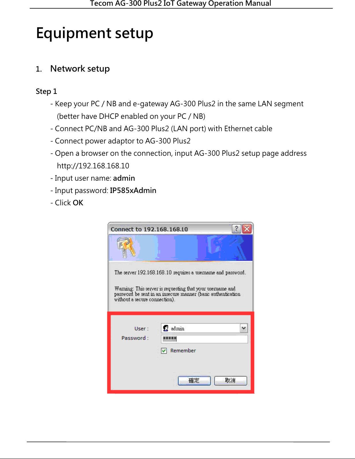
![Tecom AG-300 Plus2 IoT Gateway Operation Manual Step 2 (Skip this step for DHCP PnP network) - In main menu on the left, click [Settings] [WAN]. - In WAN connection type dropdown menu, select [STATIC (Fixed IP)] - IP address: input IP data. - Subnet mask: input subnet mask data. - Default gateway: input default gateway data. - Primary DNS server: input main DNS server data. - Secondary DNS serverinput secondary DNS server. - Click the [Apply] button at bottom of page once all settings were made successfully. Try connecting to popular web sites (e.g., edition.cnn.com and www.yahoo.com.tw to validate external networking function Set smartphone APP communication port to TCP 53100 ~53199 in case firewall management service is in existence.](https://usermanual.wiki/Tecom-Co/AG300PLUS2/User-Guide-3759209-Page-12.png)
![Tecom AG-300 Plus2 IoT Gateway Operation Manual 2. Account setup Step 1 In main menu on the left, click [Settings] [Unit pairing] before selecting [Add] button. Step 2 Check the [Select] column before selecting the [Edit] button](https://usermanual.wiki/Tecom-Co/AG300PLUS2/User-Guide-3759209-Page-13.png)
![Tecom AG-300 Plus2 IoT Gateway Operation Manual - Name : input user name. - . - . - [ ] - [ ] .](https://usermanual.wiki/Tecom-Co/AG300PLUS2/User-Guide-3759209-Page-14.png)
![Tecom AG-300 Plus2 IoT Gateway Operation Manual - To edit user account: check the [Select] column; click the [Edit] button, and the existing settings of the account displays for you to change. - To delete user account: when the user was disconnected check the [Select] column, click the [Delete] button to remove the account. 3. VB200 setup This portable vibration diagnosis instrument supports up to 4 magnetic VB-200ST(U)/VB-200SC for concurrent measurement, analysis, and diagnosis; see section "RS485 wiring" for its installation. The VB-200 series vibration gauge comes with default value of RS485 ID at 15; one RS485 cable may connect one VB-200 series vibration gauge only; factory default of this portable vibration diagnosis instrument may connect two VB-200 series vibration gauge; please connect the latter to the 1st and 2nd RS485 port of AG-300 Plus2; the 3rd and 4th RS485 ports are reserved for expansion in the future; to connect 3 or more VB-200 series vibration gauge you need to add RS485 device in the management page first. Connect only one VB-200 series vibration gauge in a RS485 port, otherwise the system may fail to identify individual gauge as each of them bears the same RS485 ID value of 15; please make sure only one VB-200 series vibration gauge is connected to one RS485 port to prevent setup confusion. Please follow steps below to add the 3rd VB-200 series vibration gauge: - In main menu on the left, click [Settings] [RS485]. - The VB200 page displays and click [Add] option in it.](https://usermanual.wiki/Tecom-Co/AG300PLUS2/User-Guide-3759209-Page-15.png)
![Tecom AG-300 Plus2 IoT Gateway Operation Manual - Name: "VB-200" or any name you like. - Line: select line 3 ~ 4 (line 1~2 added by factory default). - RS485 ID: please fill in a value compliant with your RS485 configuration (this system support RS485 ID in range of 0-15). - Click [Save] button at bottom of page.](https://usermanual.wiki/Tecom-Co/AG300PLUS2/User-Guide-3759209-Page-16.png)
![Tecom AG-300 Plus2 IoT Gateway Operation Manual - To edit the settings of VB-200: check the [Select] column, click the [Edit] button, and the existing settings display for you to change. - To delete settings of VB-200: check the [Select] column, click the [Delete] button to remove the VB-200 vibration gauge. - To add VB-200 vibration gauge: click the [Add] button to add new VB-200 setup.](https://usermanual.wiki/Tecom-Co/AG300PLUS2/User-Guide-3759209-Page-17.png)
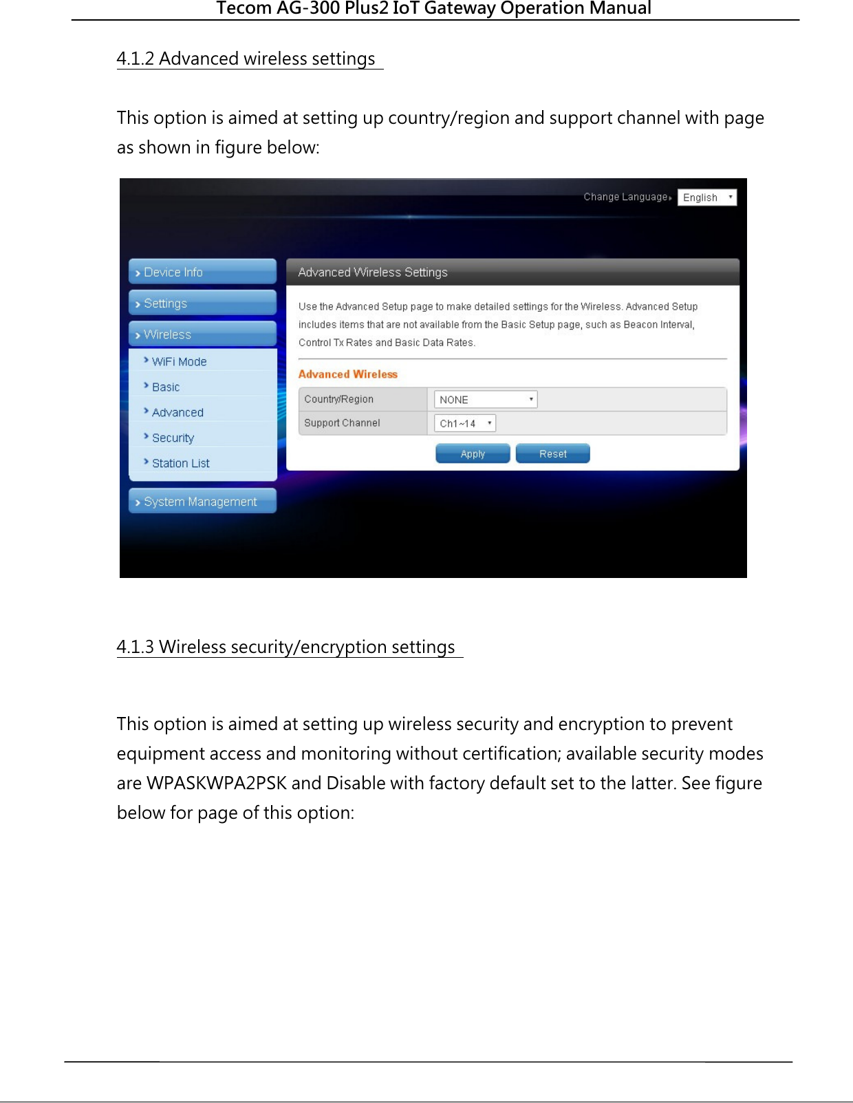
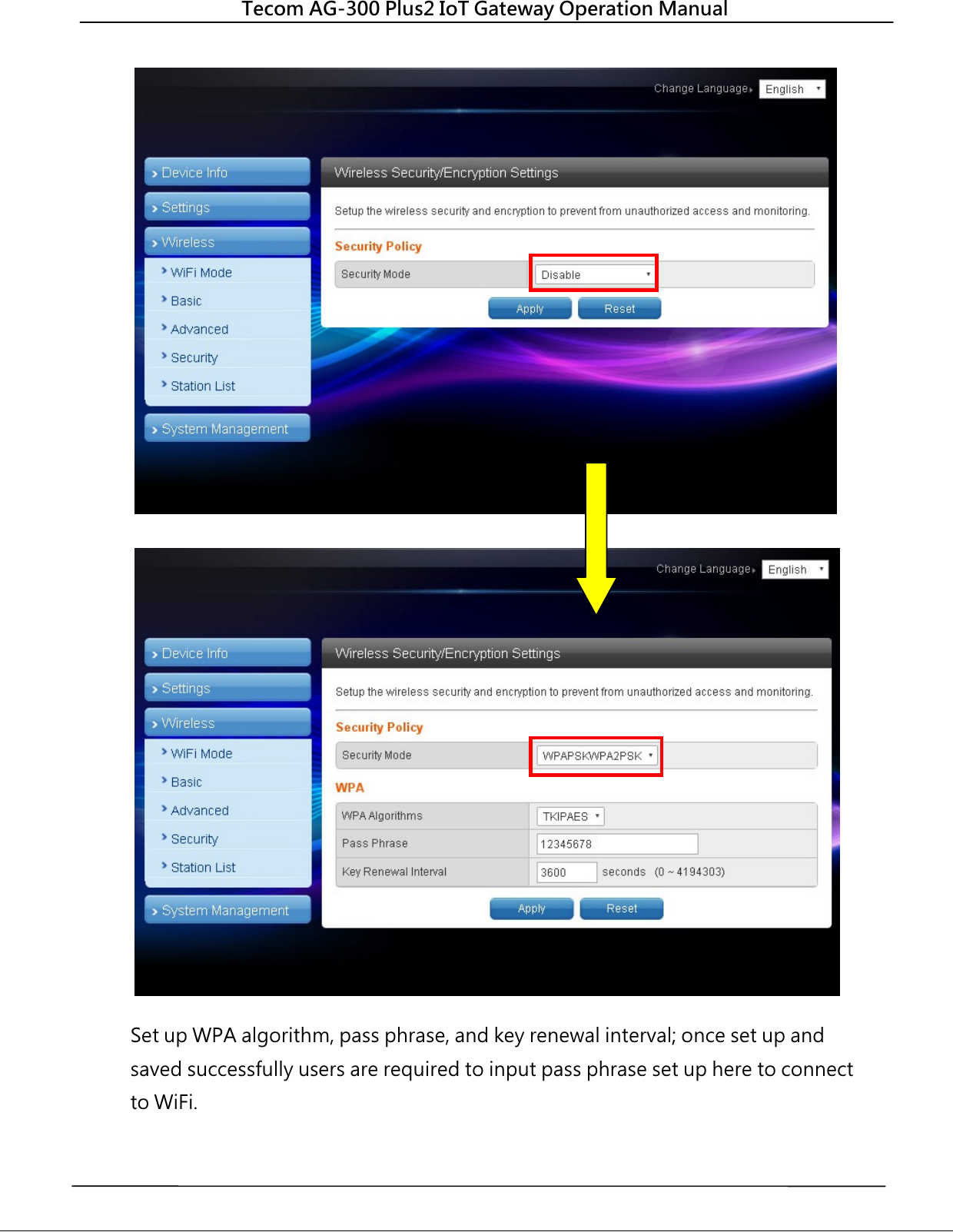
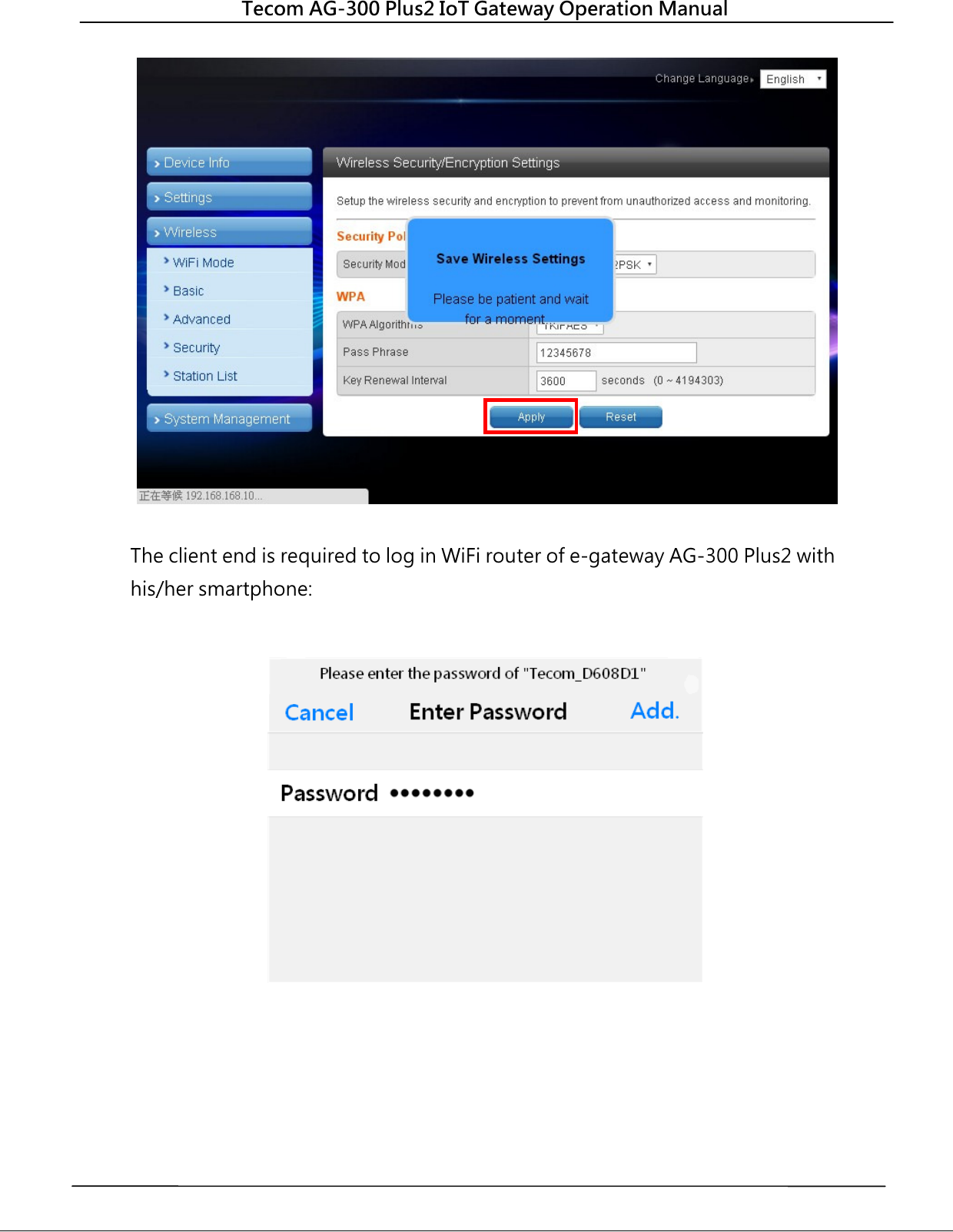
![Tecom AG-300 Plus2 IoT Gateway Operation Manual 4.1.1 Basic wireless settings This option enables user to set up basic wireless communication parameters including network name and mode with WiFi function default to Enable. WiFi [Enable] page: see figure below: WiFi [Disable] page: see figure below:](https://usermanual.wiki/Tecom-Co/AG300PLUS2/User-Guide-3759209-Page-19.png)
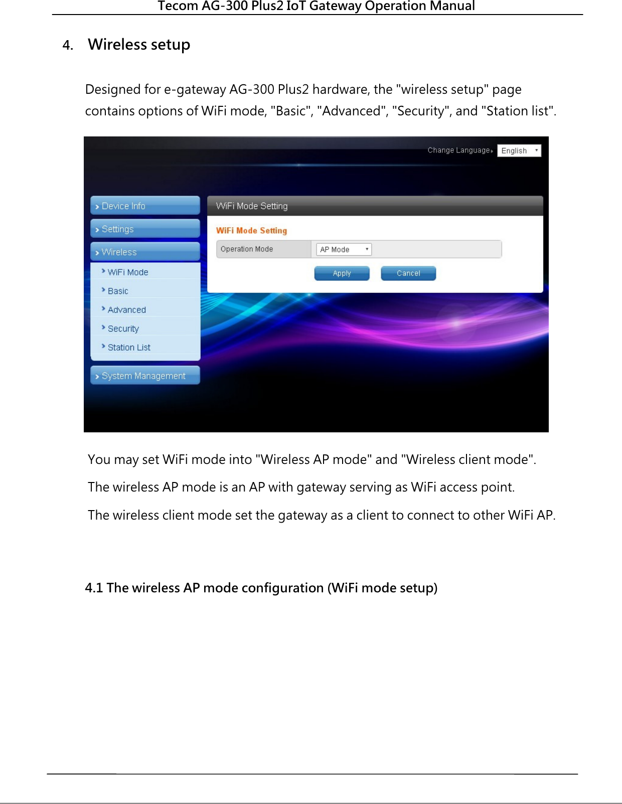
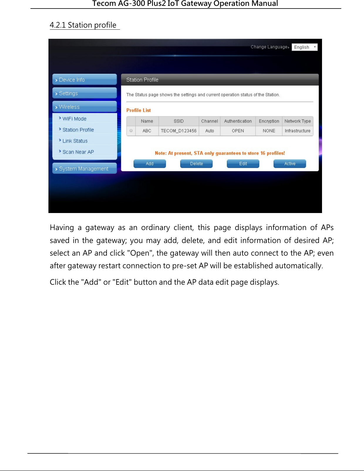
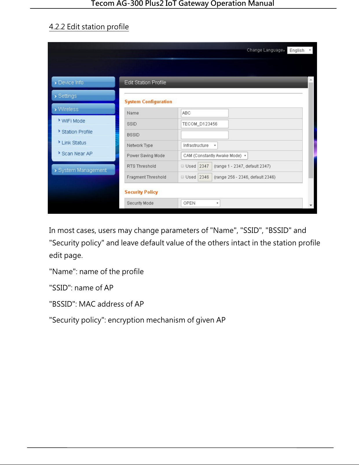
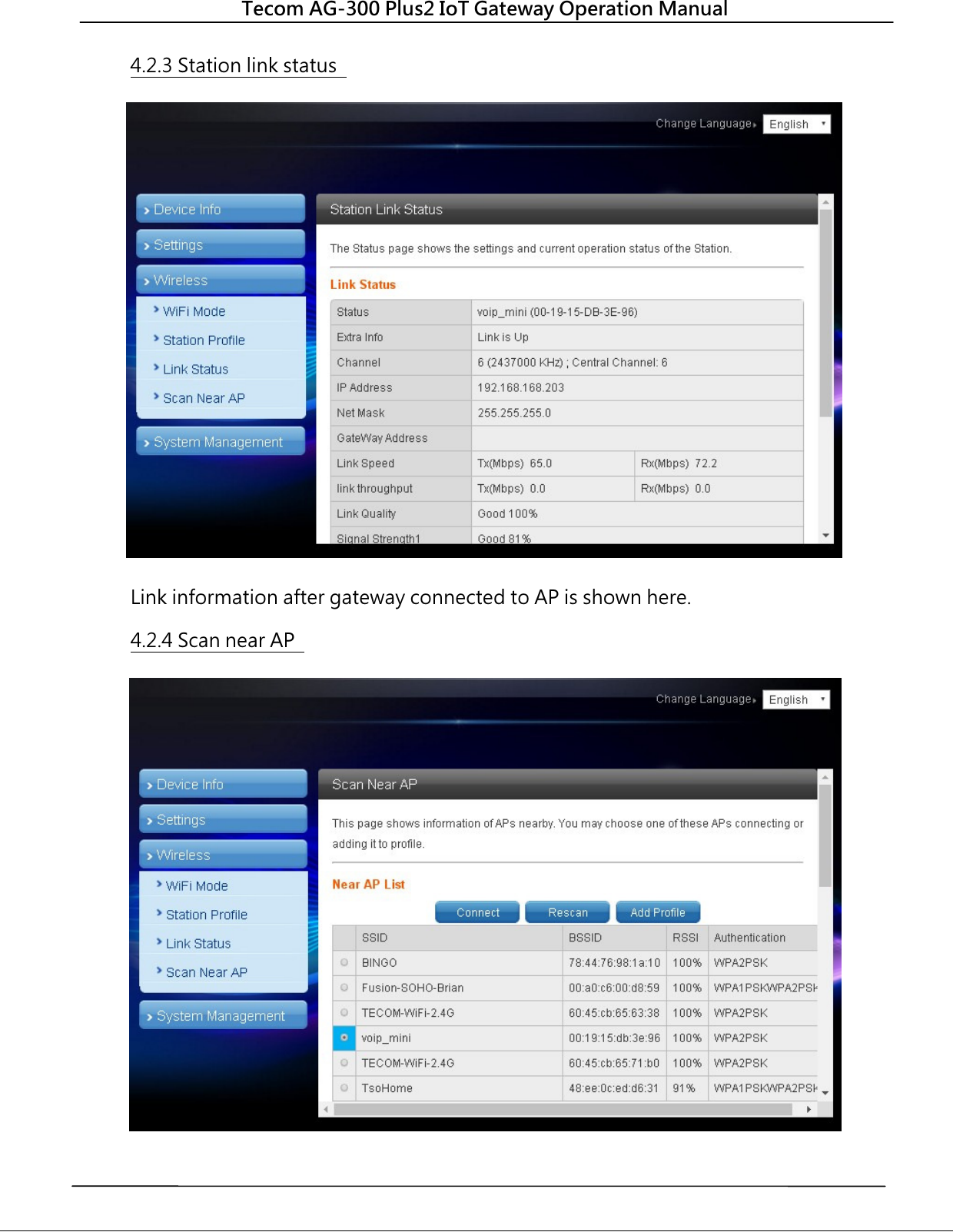
![Tecom AG-300 Plus2 IoT Gateway Operation Manual 4.1.4 Station list Users of this solution may monitor clients connected to AP. 4.2 WiFi mode setting Select STA mode and click [Apply] in the WiFi mode setting.](https://usermanual.wiki/Tecom-Co/AG300PLUS2/User-Guide-3759209-Page-23.png)
![Tecom AG-300 Plus2 IoT Gateway Operation Manual APP software operation By following steps set in homepage of [Pro-3200 installation and measurement quick guide 1-2-3] users of this vibration diagnosis instrument may auto connect to it for instant operation data query and vibration diagnosis analysis and report without account setup and login. Follow steps below to set up your vibration diagnosis instrument for user account and server IP address. 1. Open the [Vibration Diagnosis] APP on your smartphone 2. This vibration diagnosis instrument provides PnP quick online diagnosis; log in account 100~119 without other parameter settings as shown in figure below: 3. Input Account: 100, Password: 100, Address: 192.168.168.10, Name: 100 or custom values defined earlier; initial values of account, password, and name are set to be the same; the system comes with 20 accounts (100~119) for equipment pairing use. - Account: 100 (there are 20 accounts available with ID in range of 100-119). - Password: your personal password (better the same as account ID). - Server IP: the IP address or server ID set by AG-300 Plus2. - Server name: name of AG-300 Plus2 server. 100 100 192.168.168.10100](https://usermanual.wiki/Tecom-Co/AG300PLUS2/User-Guide-3759209-Page-28.png)
![Tecom AG-300 Plus2 IoT Gateway Operation Manual 4. Check [Remember account], press [Log in], and the vibration diagnosis instrument page displays. 5. Please follow APP wizard to execute the following vibration diagnosis operation: (1) Vibration measures: select this option to monitor vibration readings of target E&M equipment; note that this is a pure monitoring function and without data saving. (2) Diagnosis: Select this option for vibration measurement, analysis, and diagnosis with steps: [Input equipment data] [Vibration measurement] [Analysis diagnosis]; please follow APP wizard to get complete vibration analysis and diagnosis report. (3) Report management: Access and manage reports provided by the system; distribute them to relevant personnel by email or communication software anywhere anytime. 6. If you have checked the [Remember Account] option, you may click the "V" icon on the right of account direct and fast login as shown in figure below: 7. Please check steps below if you failed to login: (1) Is networking function of your smartphone enabled? (2) Is network signal of smartphone in good conditions? (3) Is AG-300 Plus2 powered on? (4) AG-300 Plus2 equipment pairing set up? (5) Is AG-300 Plus2 networking function in normal conditions? (6) Is smartphone and AG-300 Plus2 WiFi [connected]? 1 21 31 Quick login step 1-2-3 Click the Click Press](https://usermanual.wiki/Tecom-Co/AG300PLUS2/User-Guide-3759209-Page-29.png)
![Tecom AG-300 Plus2 IoT Gateway Operation Manual Note: you may get Host ID on the AG-300 setup page once it is connected to external network. In the main menu on the left, click [Device Info] [Status Overview] option, to get Host ID in the System Info window. TECOM Corp., Ltd No.23, R & D Rd. II, Hsinchu Science-based Industrial Park, Hsinchu, Taiwan, 300 TEL: +886-3-5775141 FAX: +886-3-5776855 http://www.tecom.com.tw Distributor Ver: 02 2017.11 This manual may be modified when necessary because of improvement of the product, modification, or change in specifications. This manual is subject to change without notice.](https://usermanual.wiki/Tecom-Co/AG300PLUS2/User-Guide-3759209-Page-30.png)