User manual

Copyright © 2017, All Rights Reserved.
Ver: R01 D/C: 106-1121
AG-300 Plus2
Gateway
Operation Manual

Federal Communications Commission (FCC) Statement
Statement shall be listed in the label
(if the product is smaller than palm size, it could be listed in user manual for instead.)
This device complies with Part 15 of the FCC Rules.
Operation is subject to the following two conditions:
1) this device may not cause harmful interference and
2) this device must accept any interference received, including interference that may cause
undesired operation of the device.
Statement shall be listed in the manual
15.21
You are cautioned that changes or modifications not expressly approved by the part responsible
for compliance could void the user’s authority to operate the equipment.
15.105(b)
This equipment has been tested and found to comply with the limits for a Class B digital device,
pursuant to part 15 of the FCC rules. These limits are designed to provide reasonable protection
against harmful interference in a residential installation. This equipment generates, uses and can
radiate radio frequency energy and, if not installed and used in accordance with the instructions,
may cause harmful interference to radio communications. However, there is no guarantee that
interference will not occur in a particular installation. If this equipment does cause harmful
interference to radio or television reception, which can be determined by turning the equipment off
and on, the user is encouraged to try to correct the interference by one or more of the following
measures:
-Reorient or relocate the receiving antenna.
-Increase the separation between the equipment and receiver.
-Connect the equipment into an outlet on a circuit different from that to which the receiver is
connected.
-Consult the dealer or an experienced radio/TV technician for help.
This device complies with Part 15 of the FCC Rules. Operation is subject to the following
two conditions:
1) this device may not cause harmful interference and
2) this device must accept any interference received, including interference that may cause
undesired operation of the device.
FCC RF Radiation Exposure Statement:
This equipment complies with FCC RF radiation exposure limits set forth
for an uncontrolled environment. This equipment should be installed and
operated with a minimum distance of 20 centimeters from your body.
USB Port only connection Vibration gauge (VB-200STU)

Tecom AG-300 Plus2 IoT Gateway Operation Manual
Table of contents
Overview ............................................................................................................................................3
AG-300 Plus2 Configuration ........................................................................................................5
1. System structure ..............................................................................................................5
2. Equipment wiring ............................................................................................................5
3. RS485 wiring .....................................................................................................................7
4. Power bank wiring...........................................................................................................8
5. Equipment dimension....................................................................................................8
6. AG-300 Plus2 view...........................................................................................................9
Equipment setup............................................................................................................................10
1. Network setup................................................................................................................10
2. Account setup.................................................................................................................12
3. VB200 setup ....................................................................................................................14
4. Wireless setup ................................................................................................................17
4.1 The wireless AP mode configuration (WiFi mode setup) .........................17
4.2 WiFi mode setting................................................................................................22
5. Hardware setup..............................................................................................................26
APP software operation...............................................................................................................27

Tecom AG-300 Plus2 IoT Gateway Operation Manual
Overview
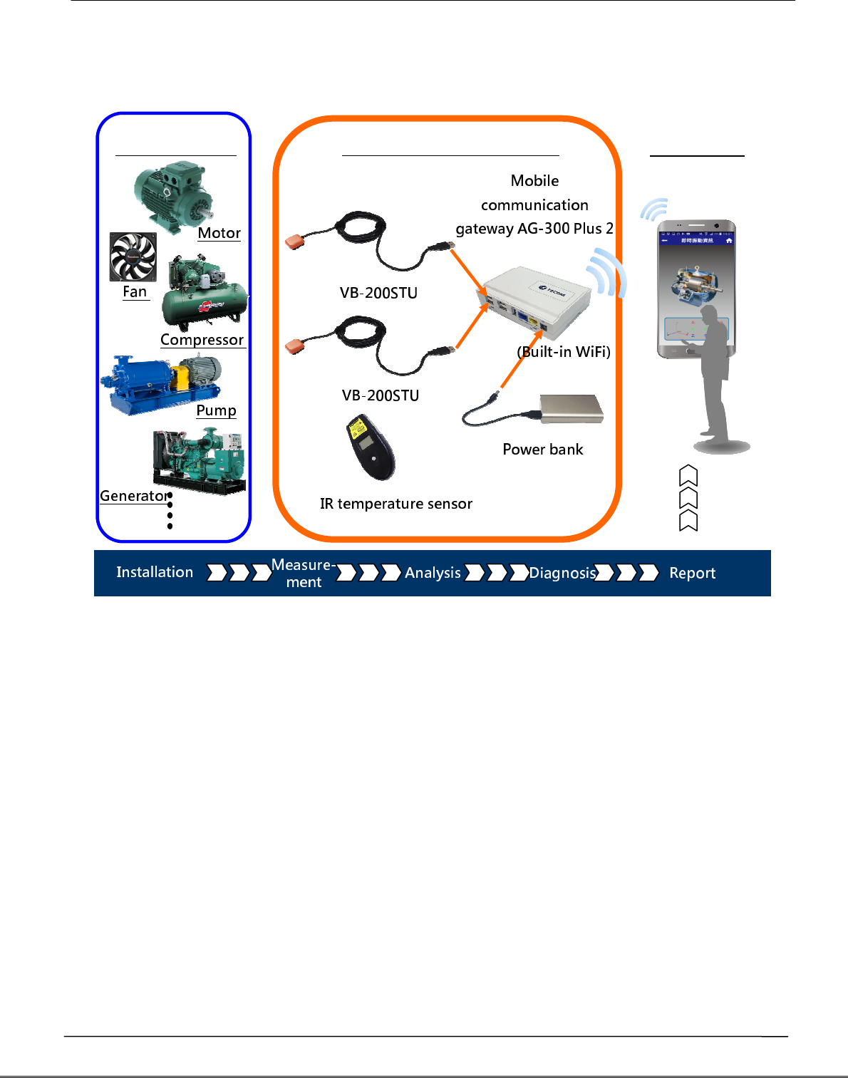
Tecom smart portable vibration diagnosis instrument is one of the most innovative
mobile maintenance products in the world. By making the most of IoT, sensor, and
management software technology it is designed to measure vibration of running E&M
equipment without extra power cord or network cable. With fully PnP based
convenience, it is ideal for small and medium size manufacturers and enterprises in
pursuing productivity 4.0.
Featuring IoT WiFi gateway (AG-300 Plus2), integrated vibration gauge VB-200STU, IR
temperature sensor, power bank, and iOS and Android platform available diversified
smartphone APP (which can be downloaded, installed, and used immediately), Tecom
smart portable vibration diagnosis instrument system is ideal for equipment
installation or maintenance engineers for measuring temperature and vibration at
equipment power contact, E&M, rotary machinery, and motor on the spot. In addition,
it combines measurements made on site with interactive analysis and diagnosis of the
system to provide instant, helpful, and effective target E&M equipment health analysis
which, in turn, not only enable easy manufacturing E&M equipment management and
upkeep in healthy status but also prevent hazardous system shutdown from
happening.
Tecom smart portable vibration diagnosis instrument may connect up to 4 vibration
gauges for multiple diagnosis at the same time. With a breakthrough in vibration
measurement concept, it integrates vibration measurement, analysis, and diagnosis
operation in one portable device to save working hours and reduce onsite
maintenance and repair time significantly.
Tecom smart portable vibration diagnosis instrument system may help acquiring full
first commissioning operation data that is critical for later maintenance and big data
analysis for manufacturer in future product release.

Tecom AG-300 Plus2 IoT Gateway Operation Manual
In situ and instant vibration diagnosis information
Productivity 4.0
Tecom AG-300 Plus2 IoT Gateway Operation Manual
AG-300 Plus2 Configuration
1.
System structure
2.
Equipment wiring
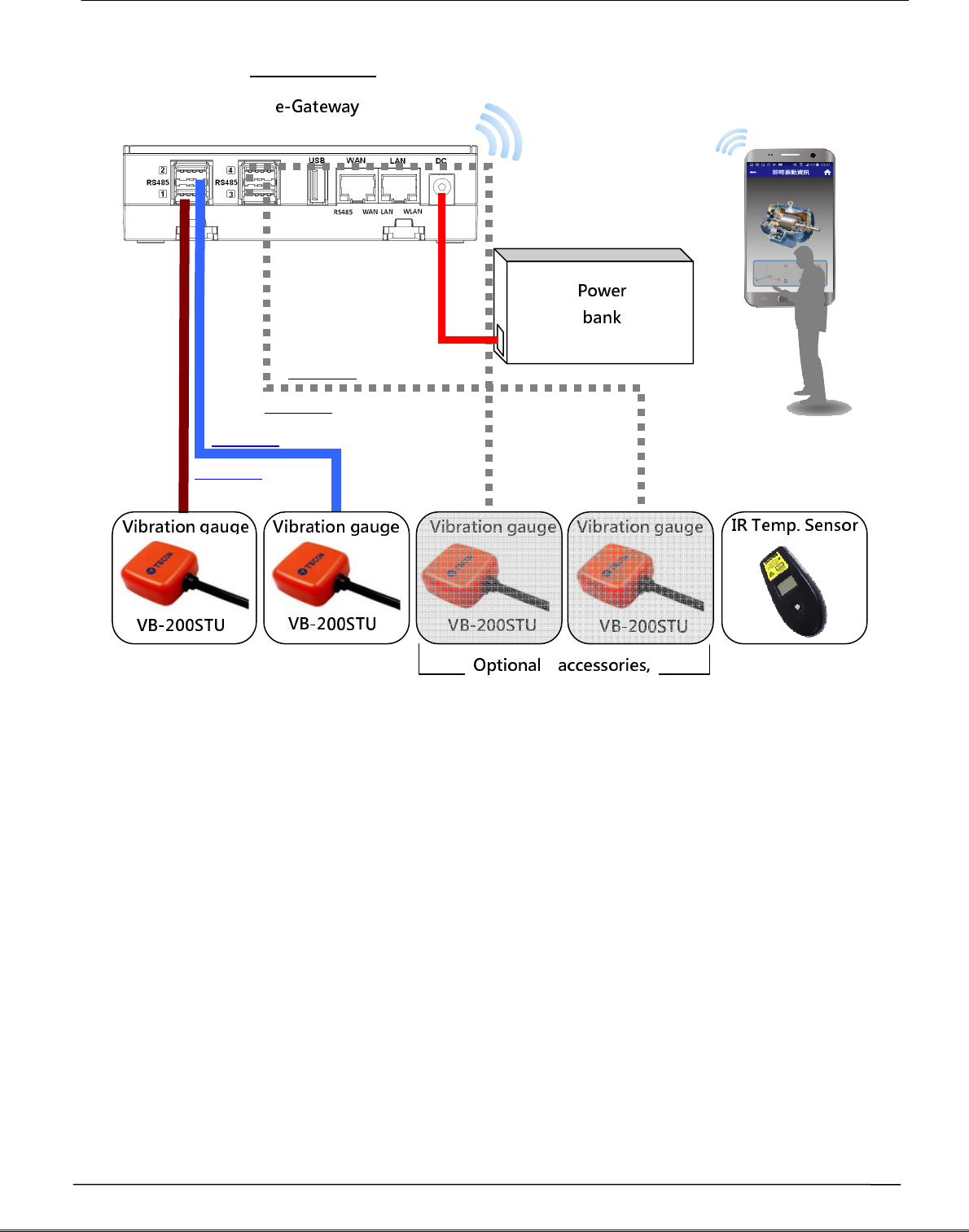
Open portable vibration diagnosis instrument carrying case and belt, and connect
them according to wiring diagram shown below.
A. Connect AG-300 Plus2 to VB-200STU with RS485(1/2)
B. Connect AG-300 Plus2 DC Jack to power bank to the power cord
C. WiFi connect smartphone to built-in WiFi router of AG-300 Plus2
D. Mount (magnetic) vibration gauge to target equipment according to its installation
guidelines
Tecom smart portable
Target E&M Vibration
Tecom AG-300 Plus2 IoT Gateway Operation Manual
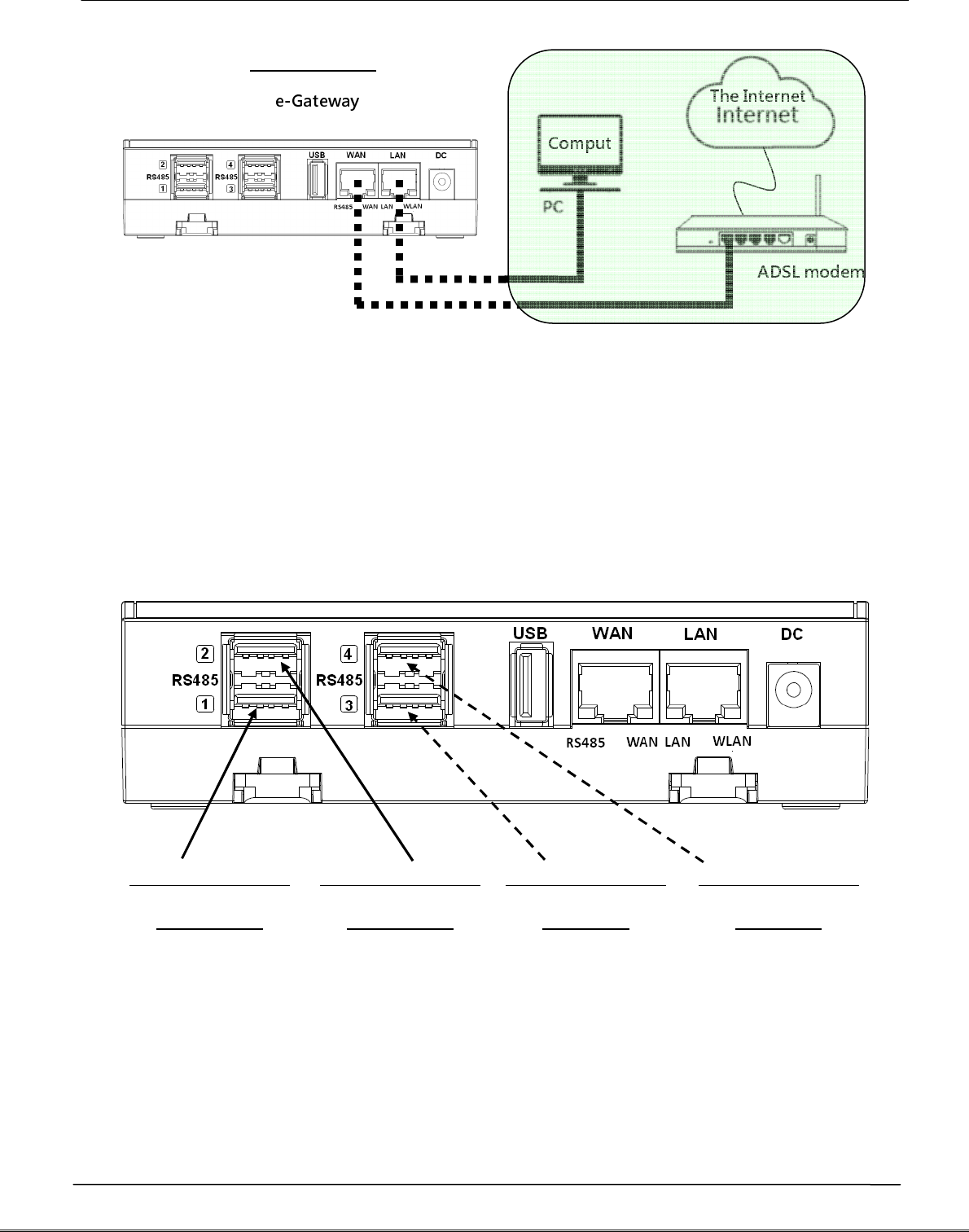
Once wired according to aforementioned diagram, your smartphone is now ready to
execute test, analysis, and diagnosis over target equipment with the "vibration
diagnosis" APP; follow the following diagram and steps E~F for computer and the
Internet connection as required.
E. Connect AG-300 Plus2 WAN port (blue) and LAN port of ADSL modem with
network cable
F. Connect AG-300 Plus2 LAN port (yellow) and PC with network cable (for system
setup only)
RS485#1
RS485#2
A
B
C
RS485
AG-300 Plus2
RS485#3
RS485#4
B-1
B-2
B-3
B-4
Tecom AG-300 Plus2 IoT Gateway Operation Manual
3.
RS485 wiring
(1) AG-300 Plus2
E-gateway AG-300 Plus2 supports up to 4 vibration gauge with RS485 (USB)
connection as shown in figure below:
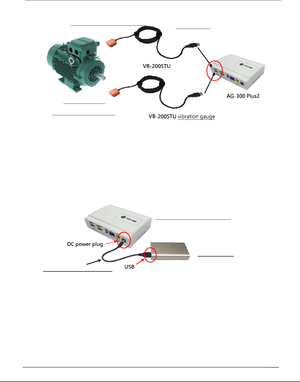
(2) VB-200STU
This portable vibration diagnosis instrument comes with 2 built-in vibration gauges
VB-200STU; featuring integrated RS485 cable and USB connector the latter may direct
connect to e-gateway AG-300 Plus2 as shown inthe figure below:
A
B
C
RS485
C
A
AG-300 Plus2
RS485 (USB) set 1
VB-200STU
RS485 (USB) set 2
VB-200STU
RS485 (USB) set 3
Reserved
RS485 (USB) set 4
Reserved
Tecom AG-300 Plus2 IoT Gateway Operation Manual
4.
Power bank wiring
This portable vibration diagnosis instrument comes with power bank power cord,
please connect DC Plug to DC jack of AG-300 Plus2 and USB connector to USB port in
power bank as shown in figure below:
5.
Equipment dimension
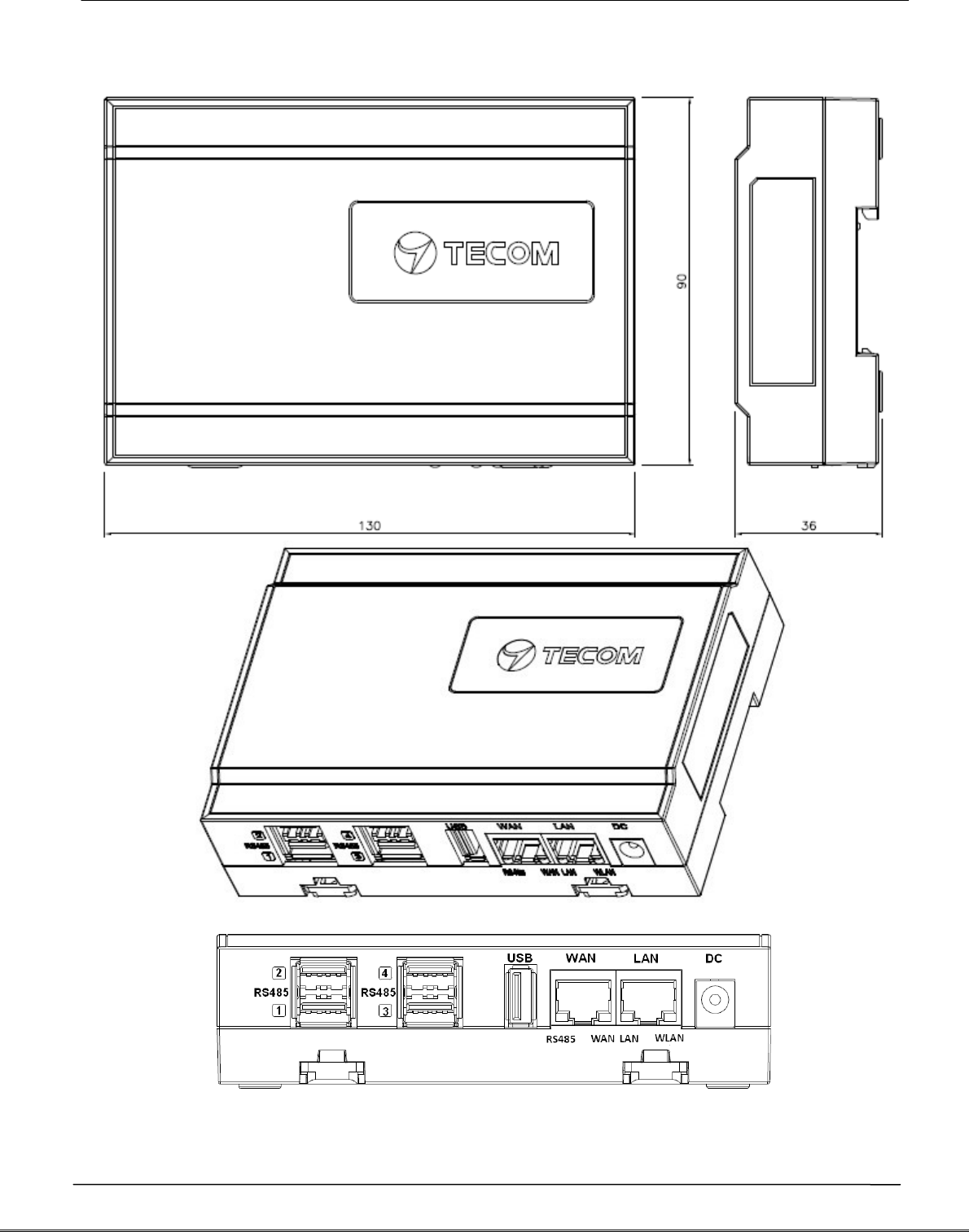
AG-300 Plus2 dimension: 130mm (length) x 90mm (width) x 36 mm (height)
RS485(USB)
Magnetic vibration gauge
Target E&M
equipment (motor)
Power bank power cord
Power bank
e-gateway AG-300 Plus2
Tecom AG-300 Plus2 IoT Gateway Operation Manual
6.
AG-300 Plus2 view
Tecom AG-300 Plus2 IoT Gateway Operation Manual
Equipment setup
1.
Network setup
Step 1
- Keep your PC / NB and e-gateway AG-300 Plus2 in the same LAN segment
(better have DHCP enabled on your PC / NB)
- Connect PC/NB and AG-300 Plus2 (LAN port) with Ethernet cable
- Connect power adaptor to AG-300 Plus2
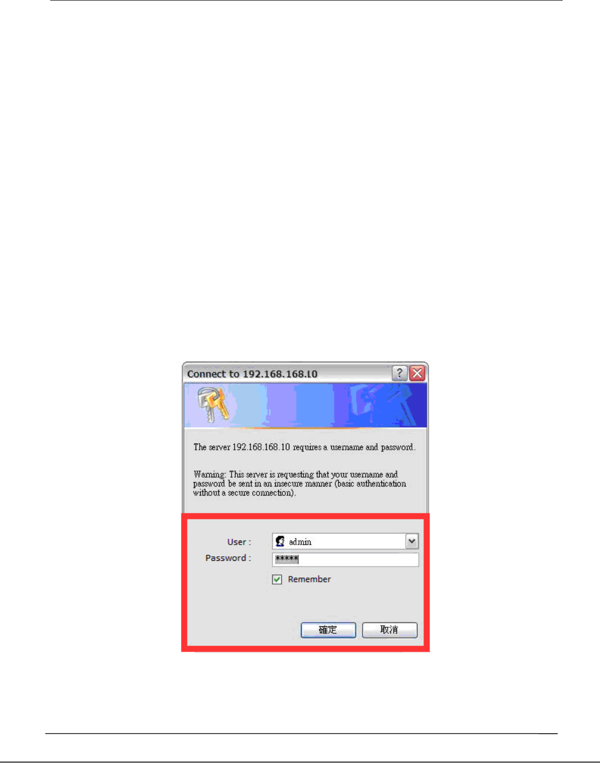
- Open a browser on the connection, input AG-300 Plus2 setup page address
http://192.168.168.10
- Input user name: admin
- Input password: IP585xAdmin
- Click OK
Tecom AG-300 Plus2 IoT Gateway Operation Manual
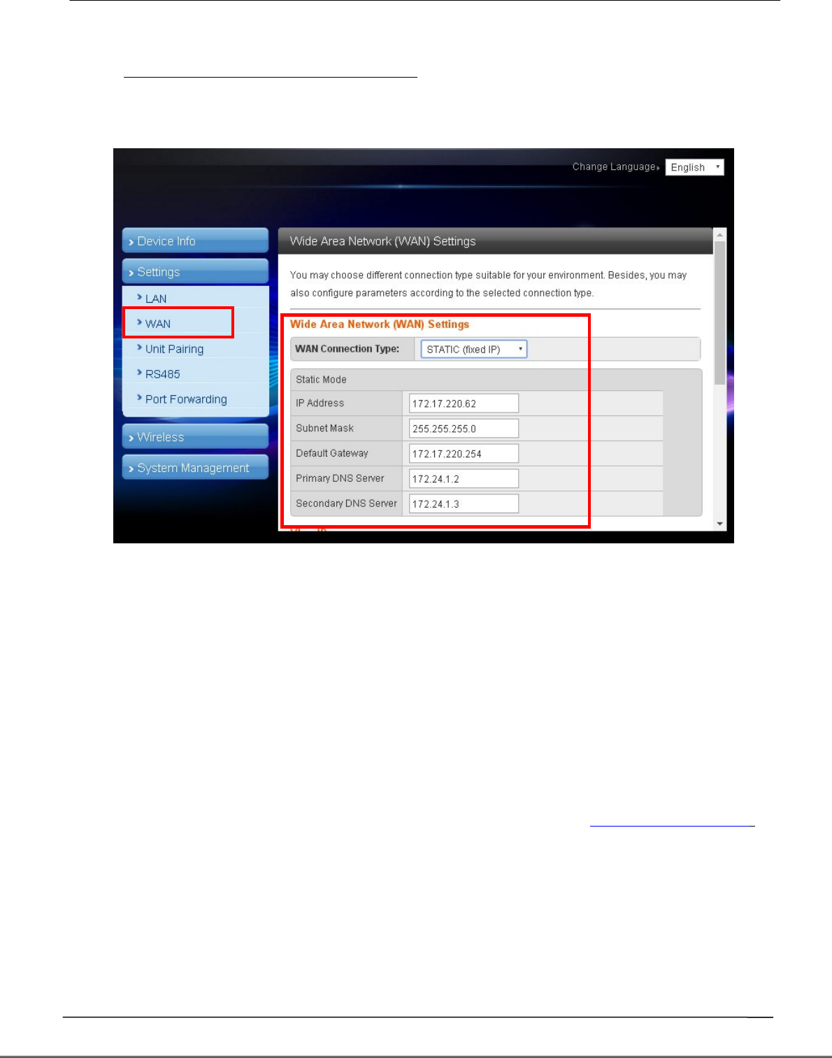
Step 2
(Skip this step for DHCP PnP network)
- In main menu on the left, click [Settings] [WAN].
- In WAN connection type dropdown menu, select [STATIC (Fixed IP)]
- IP address: input IP data.
- Subnet mask: input subnet mask data.
- Default gateway: input default gateway data.
- Primary DNS server: input main DNS server data.
- Secondary DNS serverinput secondary DNS server.
- Click the [Apply] button at bottom of page once all settings were made
successfully.
Try connecting to popular web sites (e.g., edition.cnn.com and www.yahoo.com.tw
to validate external networking function
Set smartphone APP communication port to TCP 53100 ~53199 in case firewall
management service is in existence.
Tecom AG-300 Plus2 IoT Gateway Operation Manual
2.
Account setup
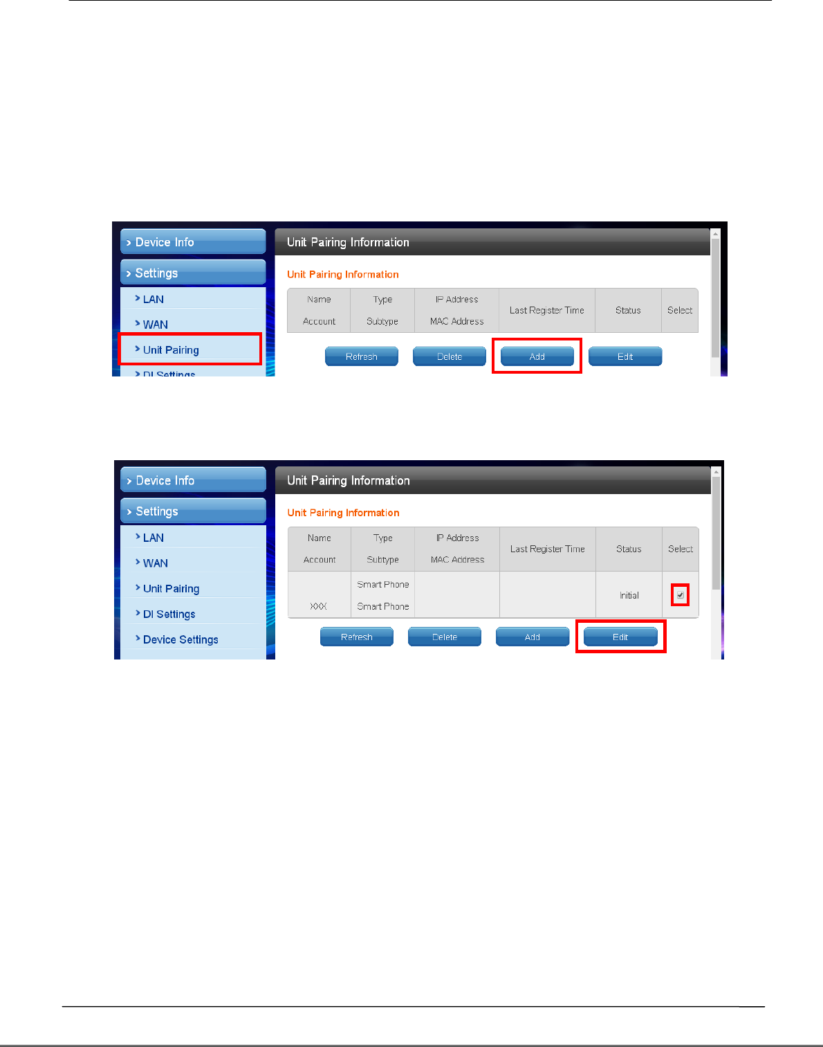
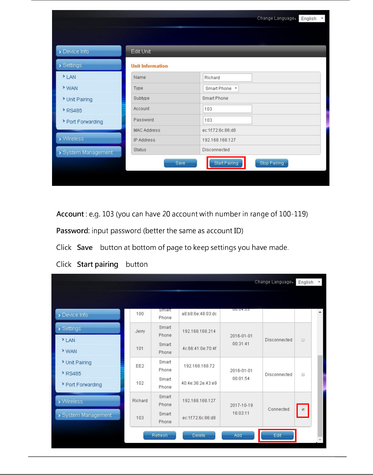
Step 1
In main menu on the left, click [Settings] [Unit pairing] before selecting [Add]
button.
Step 2
Check the [Select] column before selecting the [Edit] button
Tecom AG-300 Plus2 IoT Gateway Operation Manual
- Name : input user name.
- .
- .
- [ ]
- [ ] .

Tecom AG-300 Plus2 IoT Gateway Operation Manual
- To edit user account: check the [Select] column; click the [Edit] button, and the
existing settings of the account displays for you to change.
- To delete user account: when the user was disconnected check the [Select]
column, click the [Delete] button to remove the account.
3.
VB200 setup
This portable vibration diagnosis instrument supports up to 4 magnetic VB-
200ST(U)/VB-200SC for concurrent measurement, analysis, and diagnosis; see
section "RS485 wiring" for its installation.
The VB-200 series vibration gauge comes with default value of RS485 ID at 15; one
RS485 cable may connect one VB-200 series vibration gauge only; factory default
of this portable vibration diagnosis instrument may connect two VB-200 series
vibration gauge; please connect the latter to the 1st and 2nd RS485 port of AG-
300 Plus2; the 3rd and 4th RS485 ports are reserved for expansion in the future; to
connect 3 or more VB-200 series vibration gauge you need to add RS485 device in
the management page first.
Connect only one VB-200 series vibration gauge in a RS485 port, otherwise the
system may fail to identify individual gauge as each of them bears the same
RS485 ID value of 15; please make sure only one VB-200 series vibration gauge is
connected to one RS485 port to prevent setup confusion.
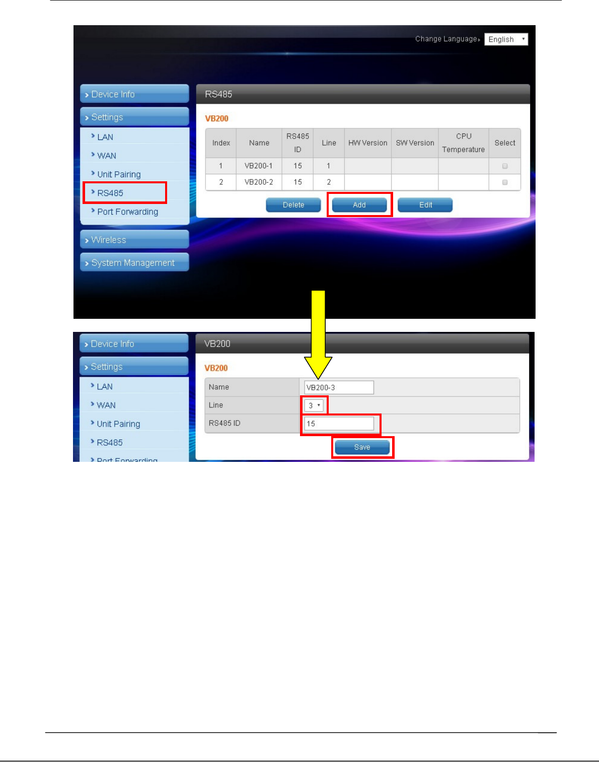
Please follow steps below to add the 3rd VB-200 series vibration gauge:
- In main menu on the left, click [Settings] [RS485].
- The VB200 page displays and click [Add]
option in it.
Tecom AG-300 Plus2 IoT Gateway Operation Manual
- Name: "VB-200" or any name you like.
- Line: select line 3 ~ 4 (line 1~2 added by factory default).
- RS485 ID: please fill in a value compliant with your RS485 configuration (this
system support RS485 ID in range of 0-15).
- Click [Save] button at bottom of page.
Tecom AG-300 Plus2 IoT Gateway Operation Manual
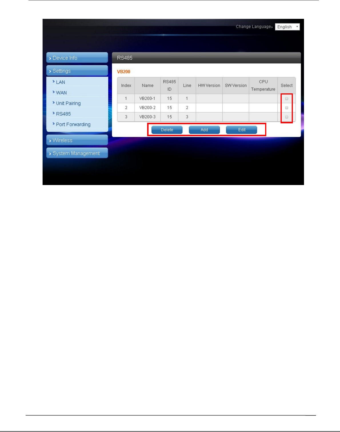
- To edit the settings of VB-200: check the [Select] column, click the [Edit] button,
and the existing settings display for you to change.
- To delete settings of VB-200: check the [Select] column, click the [Delete] button
to remove the VB-200 vibration gauge.
- To add VB-200 vibration gauge: click the [Add] button to add new VB-200 setup.
Tecom AG-300 Plus2 IoT Gateway Operation Manual
4.
Wireless setup
Designed for e-gateway AG-300 Plus2 hardware, the "wireless setup" page
contains options of WiFi mode, "Basic", "Advanced", "Security", and "Station list".
You may set WiFi mode into "Wireless AP mode" and "Wireless client mode".
The wireless AP mode is an AP with gateway serving as WiFi access point.
The wireless client mode set the gateway as a client to connect to other WiFi AP.
4.1 The wireless AP mode configuration (WiFi mode setup)
Tecom AG-300 Plus2 IoT Gateway Operation Manual
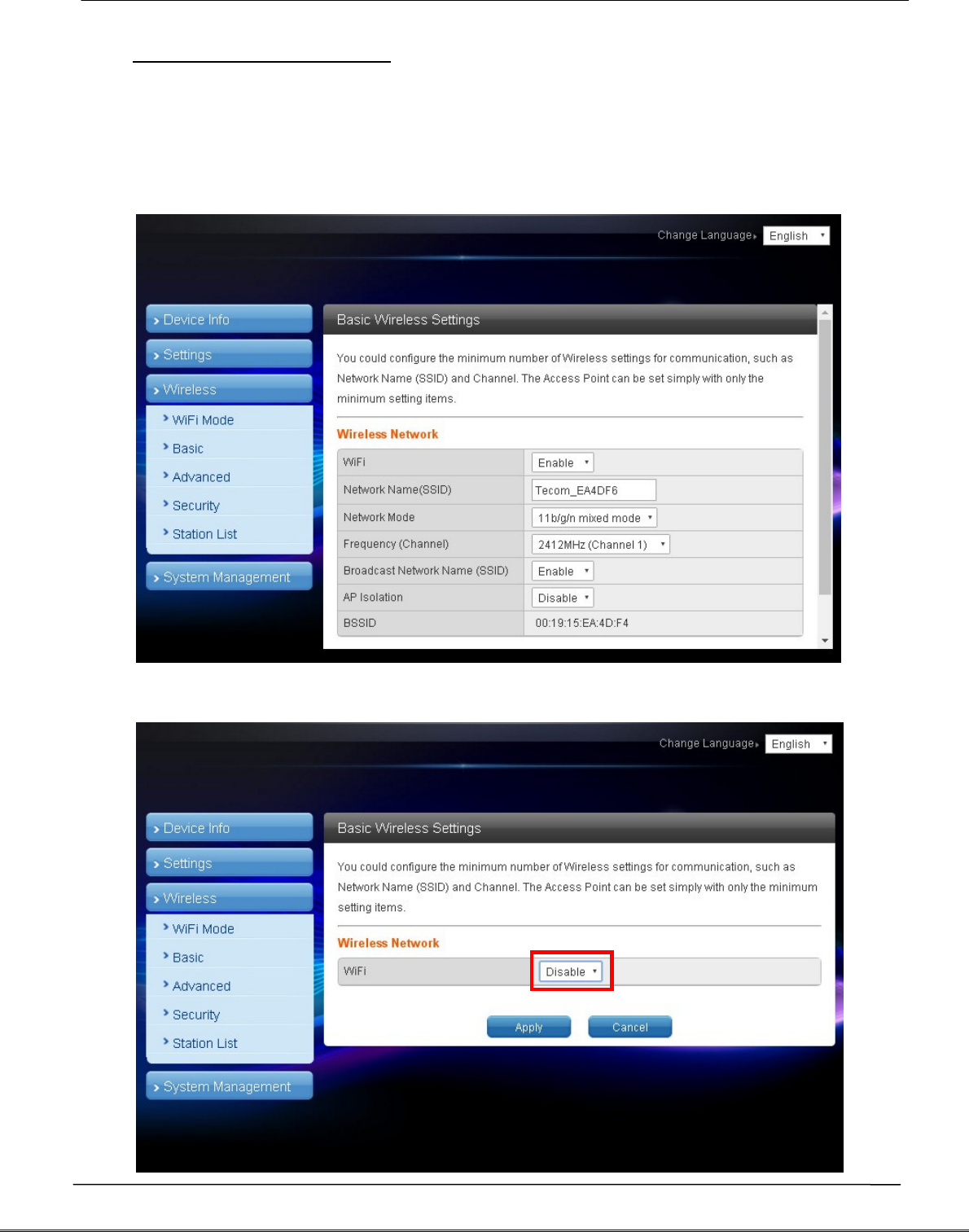
4.1.1 Basic wireless settings
This option enables user to set up basic wireless communication parameters
including network name and mode with WiFi function default to Enable. WiFi
[Enable] page: see figure below:
WiFi [Disable] page: see figure below:
Tecom AG-300 Plus2 IoT Gateway Operation Manual
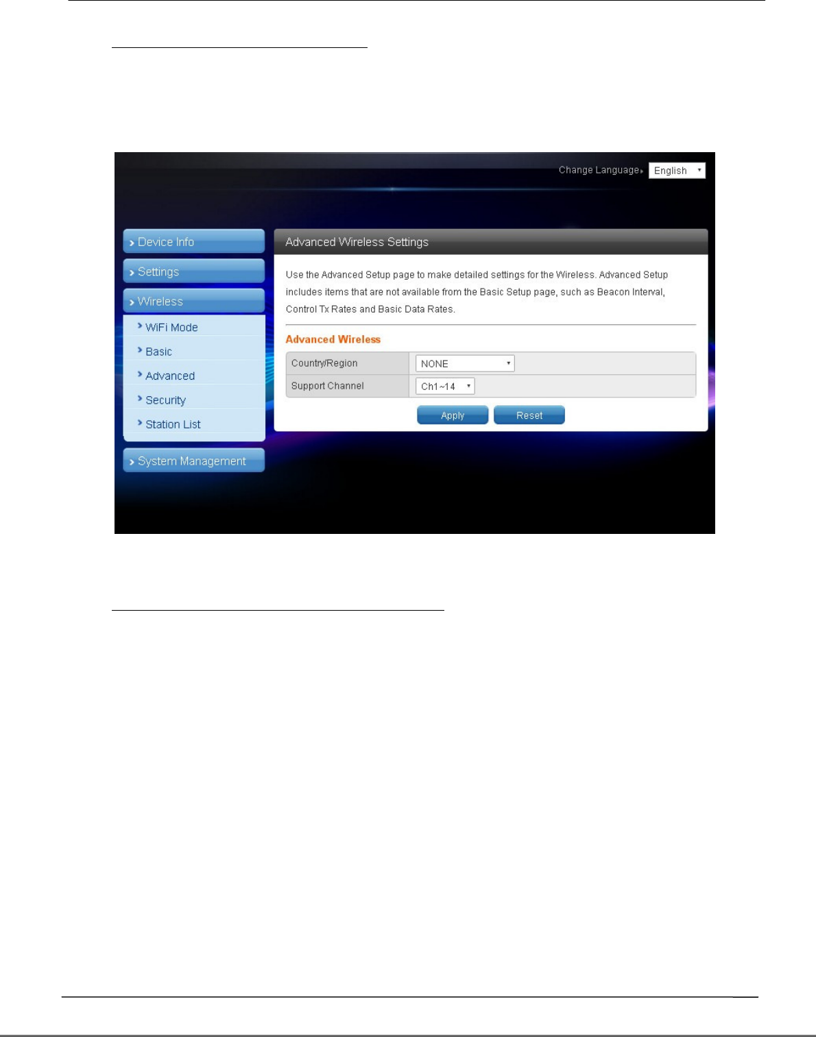
4.1.2 Advanced wireless settings
This option is aimed at setting up country/region and support channel with page
as shown in figure below:
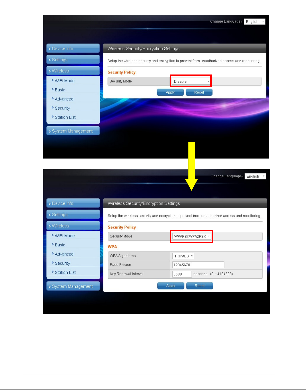
4.1.3 Wireless security/encryption settings
This option is aimed at setting up wireless security and encryption to prevent
equipment access and monitoring without certification; available security modes
are WPASKWPA2PSK and Disable with factory default set to the latter. See figure
below for page of this option:
Tecom AG-300 Plus2 IoT Gateway Operation Manual
Set up WPA algorithm, pass phrase, and key renewal interval; once set up and
saved successfully users are required to input pass phrase set up here to connect
to WiFi.
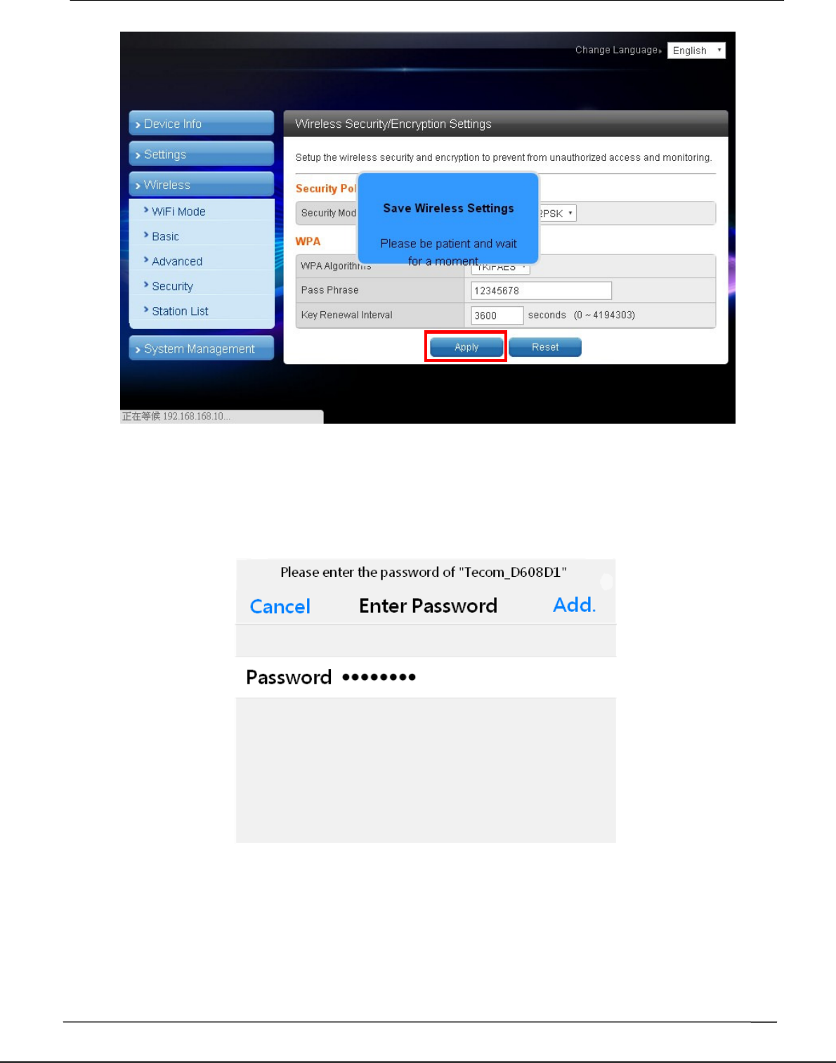
Tecom AG-300 Plus2 IoT Gateway Operation Manual
The client end is required to log in WiFi router of e-gateway AG-300 Plus2 with
his/her smartphone:
Tecom AG-300 Plus2 IoT Gateway Operation Manual
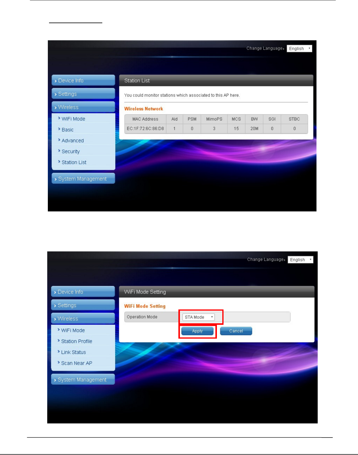
4.1.4 Station list
Users of this solution may monitor clients connected to AP.
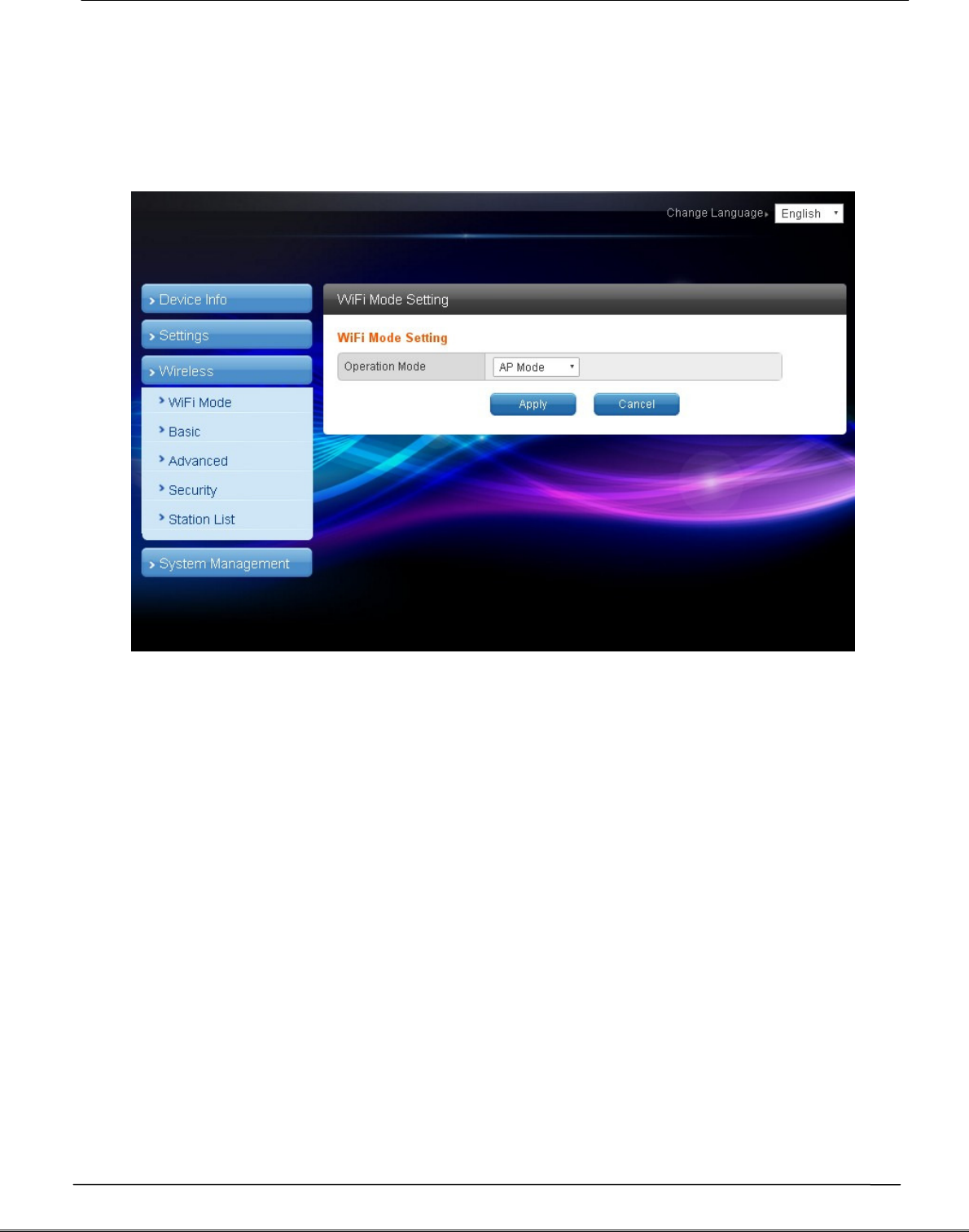
4.2 WiFi mode setting
Select STA mode and click [Apply] in the WiFi mode setting.
Tecom AG-300 Plus2 IoT Gateway Operation Manual
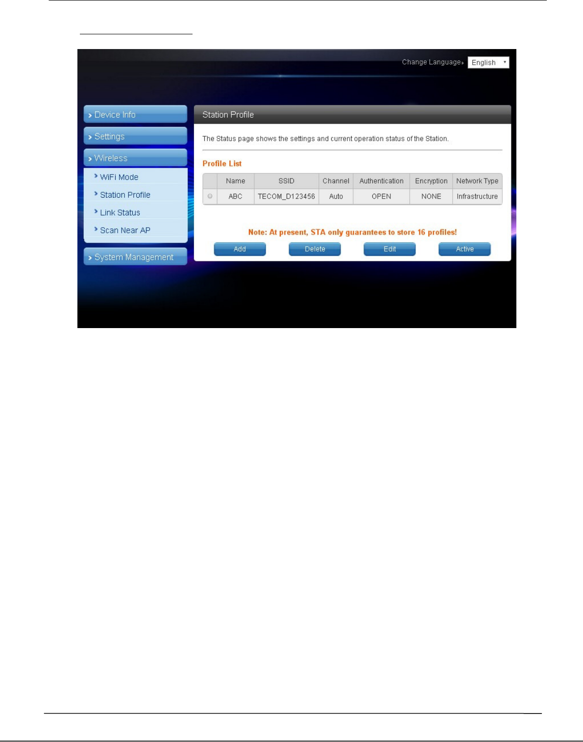
4.2.1 Station profile
Having a gateway as an ordinary client, this page displays information of APs
saved in the gateway; you may add, delete, and edit information of desired AP;
select an AP and click "Open", the gateway will then auto connect to the AP; even
after gateway restart connection to pre-set AP will be established automatically.
Click the "Add" or "Edit" button and the AP data edit page displays.
Tecom AG-300 Plus2 IoT Gateway Operation Manual
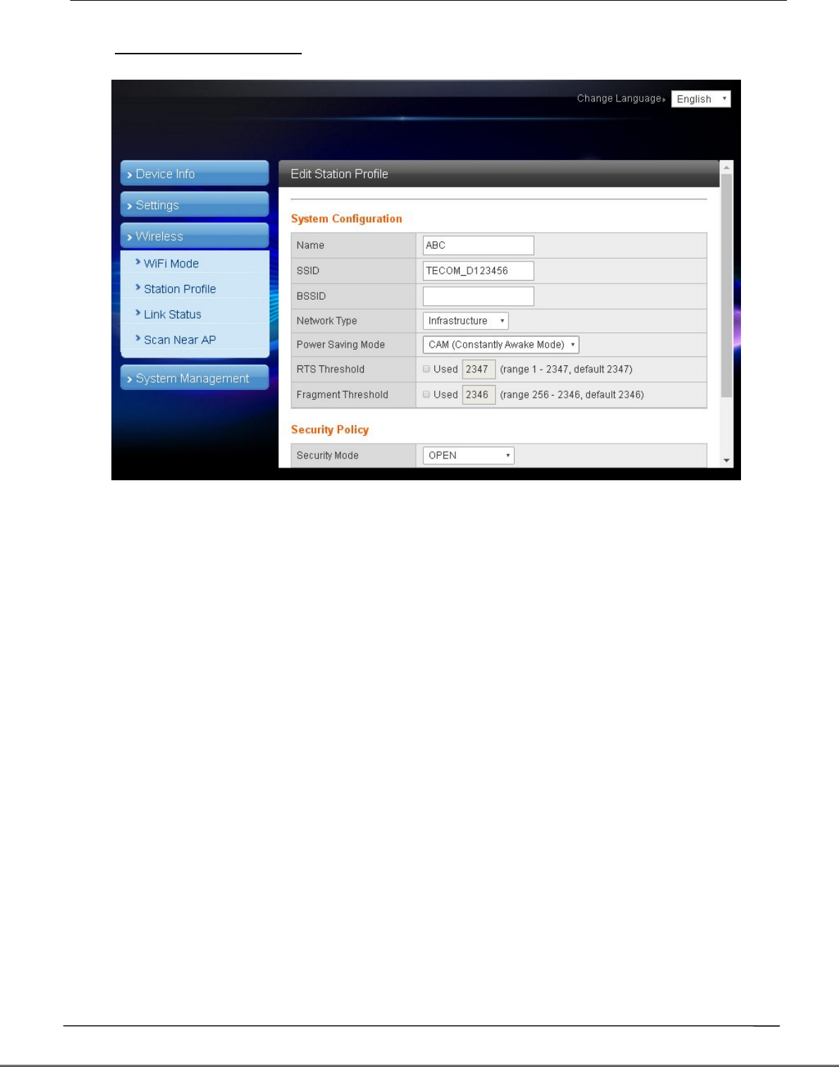
4.2.2 Edit station profile
In most cases, users may change parameters of "Name", "SSID", "BSSID" and
"Security policy" and leave default value of the others intact in the station profile
edit page.
"Name": name of the profile
"SSID": name of AP
"BSSID": MAC address of AP
"Security policy": encryption mechanism of given AP
Tecom AG-300 Plus2 IoT Gateway Operation Manual
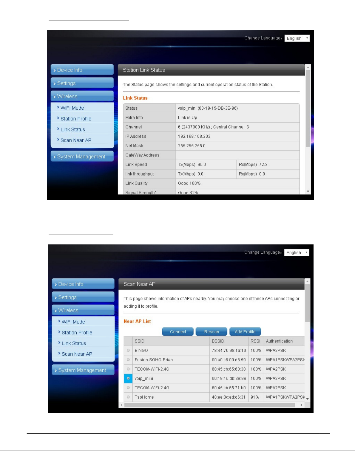
4.2.3 Station link status
Link information after gateway connected to AP is shown here.
4.2.4 Scan near AP
Tecom AG-300 Plus2 IoT Gateway Operation Manual
Scan gateway neighboring APs for information
Click "Connect" to connect the AP; data of the latter are not saved (data lost after
gateway restarted).
Click "Rescan to scan" neighboring APs once again. Scanning may fail to identify
all APs when there are many available nearby; rescan couple of times may be
needed in case like this.
Click the "Add profile" button to save AP data in station profile file.
5.
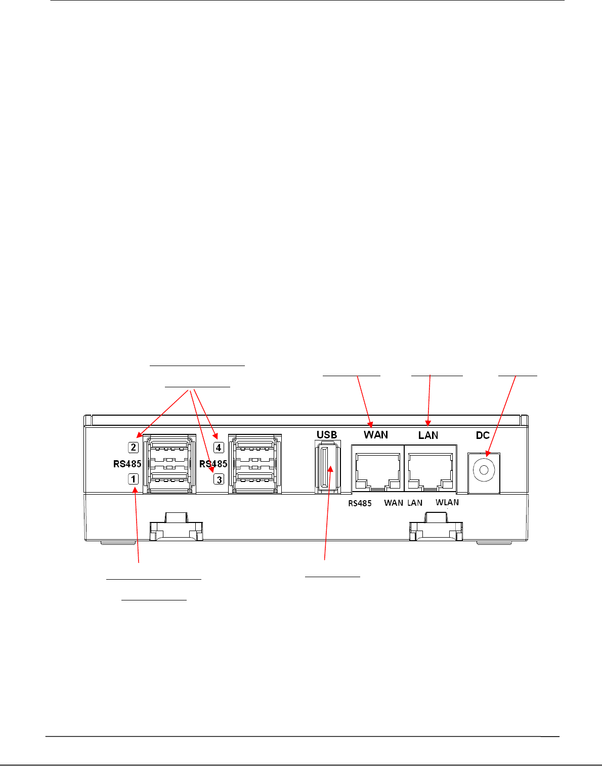
Hardware setup
AG-300 Plus2 pins definition diagram
Vibration gauge
RS485 USB
Vibration gauge
RS485 USB
LAN port WAN port Power
Reserved
Tecom AG-300 Plus2 IoT Gateway Operation Manual
APP software operation
By following steps set in homepage of [Pro-3200 installation and measurement quick
guide 1-2-3] users of this vibration diagnosis instrument may auto connect to it for
instant operation data query and vibration diagnosis analysis and report without
account setup and login. Follow steps below to set up your vibration diagnosis
instrument for user account and server IP address.
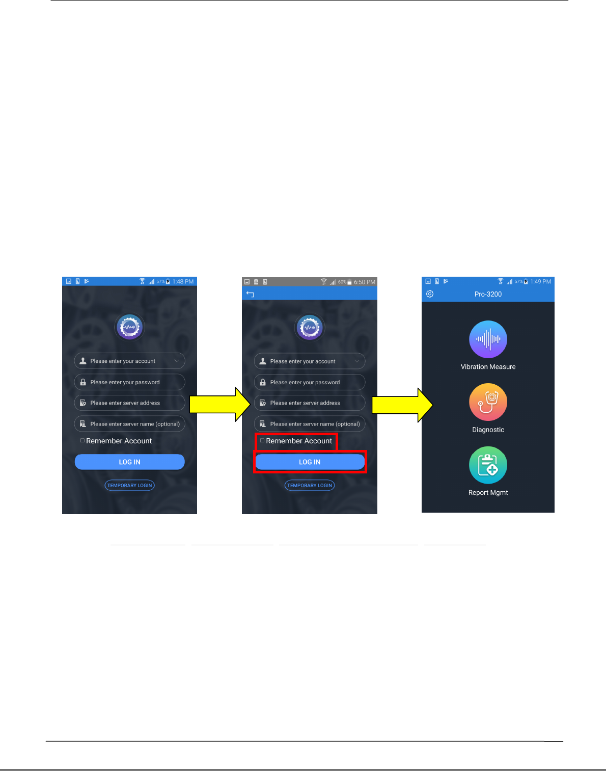
1. Open the [Vibration Diagnosis] APP on your smartphone
2. This vibration diagnosis instrument provides PnP quick online diagnosis; log in
account 100~119 without other parameter settings as shown in figure below:
3. Input Account: 100, Password: 100, Address: 192.168.168.10, Name: 100 or custom
values defined earlier; initial values of account, password, and name are set to be
the same; the system comes with 20 accounts (100~119) for equipment pairing use.
- Account: 100 (there are 20 accounts available with ID in range of 100-119).
- Password: your personal password (better the same as account ID).
- Server IP: the IP address or server ID set by AG-300 Plus2.
- Server name: name of AG-300 Plus2 server.
100
100
192.168.168.10
100
Tecom AG-300 Plus2 IoT Gateway Operation Manual
4. Check [Remember account], press [Log in], and the vibration diagnosis instrument
page displays.
5. Please follow APP wizard to execute the following vibration diagnosis operation:
(1) Vibration measures: select this option to monitor vibration readings of target
E&M equipment; note that this is a pure monitoring function and without data
saving.
(2) Diagnosis: Select this option for vibration measurement, analysis, and
diagnosis with steps: [Input equipment data] [Vibration measurement]
[Analysis diagnosis]; please follow APP wizard to get complete vibration
analysis and diagnosis report.
(3) Report management: Access and manage reports provided by the system;
distribute them to relevant personnel by email or communication software
anywhere anytime.
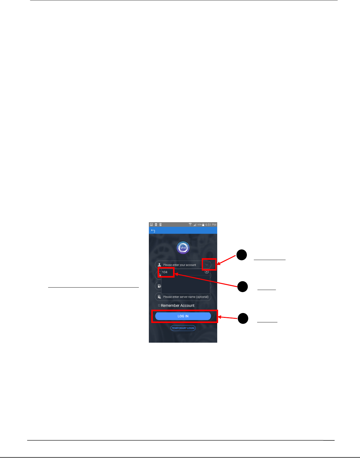
6. If you have checked the [Remember Account] option, you may click the "V" icon on
the right of account direct and fast login as shown in figure below:
7. Please check steps below if you failed to login:
(1) Is networking function of your smartphone enabled?
(2) Is network signal of smartphone in good conditions?
(3) Is AG-300 Plus2 powered on?
(4) AG-300 Plus2 equipment pairing set up?
(5) Is AG-300 Plus2 networking function in normal conditions?
(6) Is smartphone and AG-300 Plus2 WiFi [connected]?
1
2
1
3
1
Quick login step 1-2-3
Click the
Click
Press
Tecom AG-300 Plus2 IoT Gateway Operation Manual
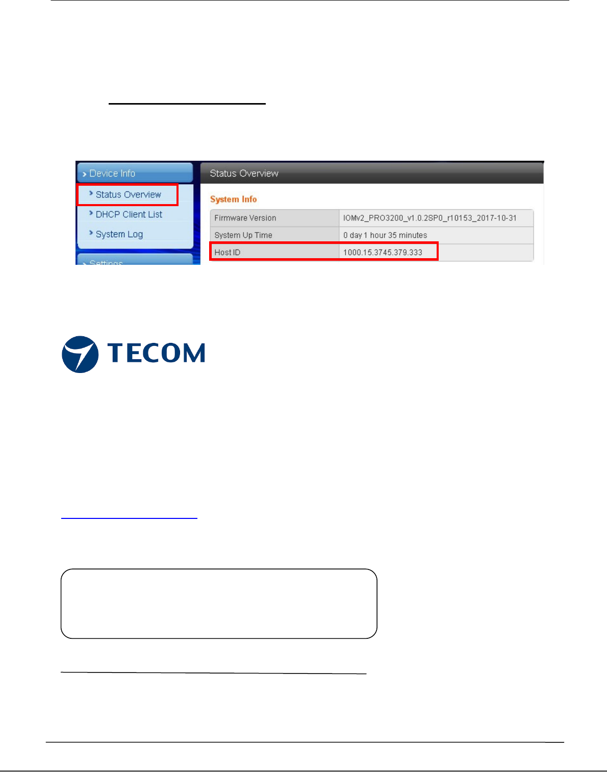
Note: you may get Host ID on the AG-300 setup page once it is connected to external
network.
In the main menu on the left, click [Device Info] [Status Overview] option, to get
Host ID in the System Info window.
TECOM Corp., Ltd
No.23, R & D Rd. II,
Hsinchu Science-based Industrial Park,
Hsinchu, Taiwan, 300
TEL: +886-3-5775141
FAX: +886-3-5776855
http://www.tecom.com.tw
Distributor
Ver: 02 2017.11
This manual may be modified when necessary because of improvement of the product,
modification, or change in specifications. This manual is subject to change without notice.