Tecom Co GCDBC1 Doorbell Camera User Manual 10010716A indd
Tecom Co Ltd Doorbell Camera 10010716A indd
Tecom Co >
User manual

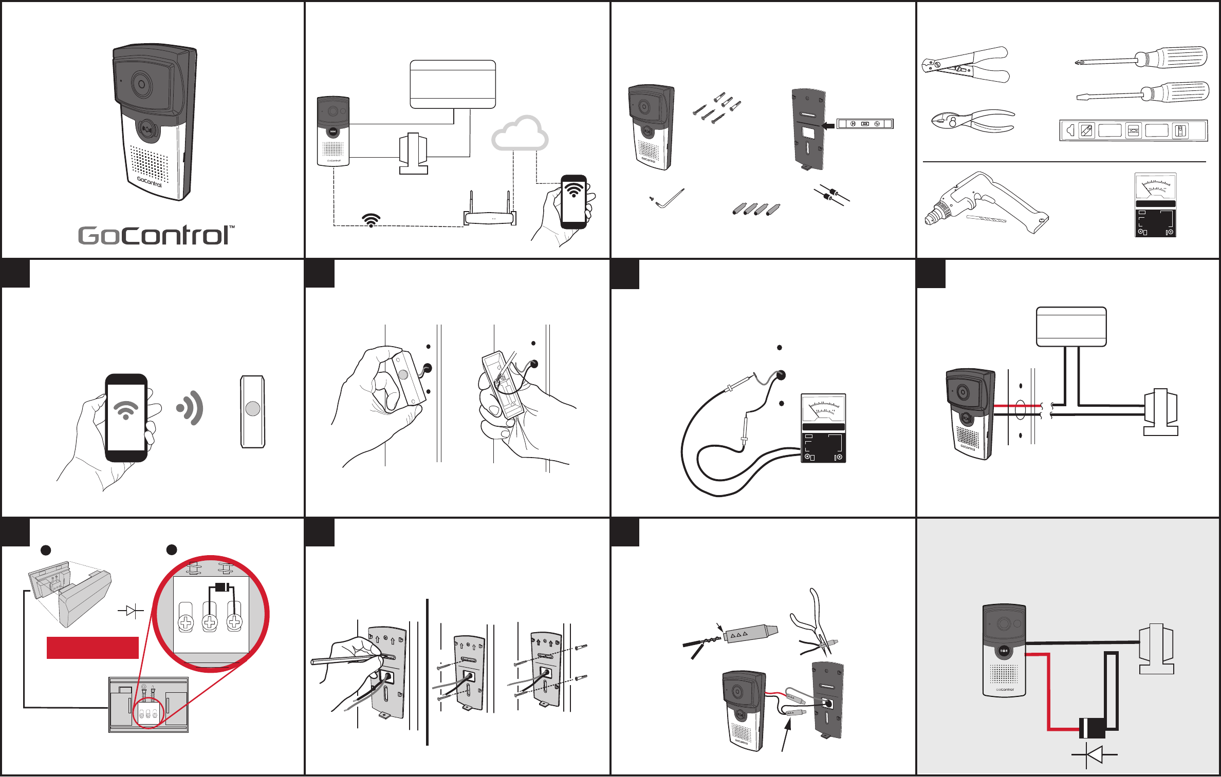
RED WIRE
BLACK WIRE
DIODE
16 VAC TRANSFORMER
BLACK WIRE: TRANSFORMER WIRE
RED WIRE: CATHODE OF DIODE
SMART
DOORBELL
CAMERA
PRINTER’S INSTRUCTIONS:
GUIDE, INSTALL, QUICK,GC-DBC-1- P/N 10010716 A - INK: BLACK - MATERIAL: 20 LB. MEAD BOND - SIZE: 17.000” X 11.000” - TOLERANCE: ± .125” - SCALE: 1-1 -FOLDING, FOLD 3 X TO FINAL SIZE 4.250” X 5.625” FINISH WITH LOGO SHOWING - SIDE 1 OF 2
GC-DBC-1
Installation Instructions
System Description
SMART
DOORBELL
CAMERA
DOORBELL
TRANSFORMER
CHIME BOX
WiFi ROUTER
WiFi COMMUNICATIONS
CLOUD
SMARTPHONE
Doorbell Camera Components
POWER DRILL WITH 1/4” BIT
WIRE STRIPPERS / CUTTER
PHILLIPS SCREWDRIVER
LEVEL
0-M
0.5
10
50
200
500
50
250
10 50 250
600 +-
AC VOLT METER
FLAT SCREWDRIVER
OPTIONAL
PLIERS
Tools For Installation
DIODES FOR
CHIME BOX (2)
USE LEVELING TOOL
TO ALIGN CAMERA
WITH LINE ON
MOUNTING PLATE
WIRE
CONNECTORS (4)
TORX
WRENCH
TORX SCREW
SMART
DOORBELL
CAMERA
SMART DOORBELL
CAMERA MOUNTING
PLATE
PHILLIPS SCREWS
(3)
ANCHORS
(3)
SMARTPHONE
EXISTING
DOORBELL
Prepare for Installation
• Go to existing doorbell location.
• Use a Smartphone connected to the installations WiFi
router to confi rm adequate signal strength (2 - 3 bars).
Existing Doorbell Removal
DISCONNECT WIRES
FROM PUSHBUTTON
DOORBELL
• Remove existing doorbell pushbutton from location.
• Disconnect wires from back of pushbutton.
Measure Voltage
0-M
0.5
10
50
200
500
50
250
10 50 250
600 +-
TEST VOLTAGE
OF WIRES
(REQUIRES
15 TO 20 VAC)
• Measure voltage of doorbell wiring with AC Volt
Meter.
• Doorbell camera works best with 15 to 20 VAC.
Mounting Doorbell Camera Plate
UP
OR
UP
UP
USE 1/4" (6.35mm) DRILL FOR
ANCHOR HOLES
SCREWS ONLY SCREWS & ANCHORS
• Use mounting plate as guide to mark holes.
Wiring Doorbell Camera
1. TWIST THEN
FEED WIRES INTO
SHORT END OF
CONNECTOR
2. CRIMP WIRES
WITH PLIERS ON
SHORT END OF
CONNECTOR
CONNECTORS
IN PLACE
• Connect doorbell wires using weather-
resistant wire connectors (included).
System Overview
BLACK WIRE: TRANSFORMER WIRE
RED WIRE: CHIME BOX WIRE
CHIME BOX
16 VAC TRANSFORMER
REAR TRANS FRONT
REAR TRANS FRONT
1 OPEN CHIME BOX
CHIME BOX FRONT VIEW WITHOUT COVER
2 INSTALL DIODE AS SHOWN
DIODE
(CATHODE
ON FRONT
TERMINAL)
IMPORTANT STEP
Installing Diode in Chime Box
1234
567Wiring Camera WITHOUT Chime
✔NOTE: Not compatible with electronic chimes
✔NOTE: It is recommended to TURN POWER OFF
after verifying voltage.
(OPTIONAL)

PRINTER’S INSTRUCTIONS:
GUIDE, INSTALL, QUICK,GC-DBC-1- P/N 10010716 A - INK: BLACK - MATERIAL: 20 LB. MEAD BOND - SIZE: 17.000” X 11.000” - TOLERANCE: ± .125” - SCALE: 1-1 FOLDING, FOLD 3 X TO FINAL SIZE 4.250” X 5.625” FINISH WITH LOGO SHOWING- SIDE 2 OF 2
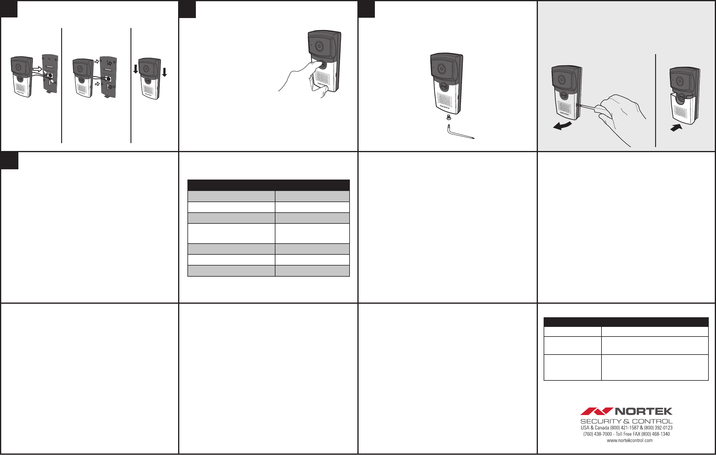
PUSH EXTRA WIRE INTO
MOUNTING PLATE SLOT
HANG DOORBELL CAMERA ON
MOUNTING PLATE TAB TOPS
SLIDE DOORBELL
CAMERA “DOWN”
Camera Installation to Mounting Plate Camera Faceplate Change-Out
USE FLATHEAD SCREWDRIVER
TO REMOVE FACEPLATE
FACEPLATE
• Order Model GC-DBC-FP Faceplate Pak to
change out doorbell camera colors.
• Use a fl athead screwdriver to remove plate.
Doorbell Camera Troubleshooting
MY DOORBELL APP
Q: The APP doesn’t save photos or videos on my smartphone?
A: Please ensure you have suffi cient memory on your smart device. Also
ensure permissions are enabled on the APP to access the device
memory.
Q: I did not receive the Authentication Code when creating an account?
A: Please check your email ‘junk’ box folder for an email from:
mydoorbell@nortek.com
NETWORK
Q: The doorbell doesn’t register on the Wi-Fi network. Why?
A: The smart doorbell camera may be out of range of your Wi-Fi network.
Move the router or install a Wi-Fi extender. Note, the Doorbell Camera
supports 2.4Ghz networks only.
Q: The smart Doorbell Camera loses network connectivity?
A: The smart Doorbell Camera may be out of range of your WiFi network.
Move the router or install a Wi-Fi extender.
STATUS COLOR
Powering Up Solid Red
Discovery Mode Flashing Green / Red
Connecting to Network Flashing Green
Connected to Network
(Normal Status)
Solid Green
Session in Progress Flashing Green
Not Connected to Network Flashing Red (Slow)
Firmware Update Flashing Red (Fast)
Regulatory Information
The GC-DBC-1 is certifi ed to comply with applicable FCC and IC rules and regulations
governing RF and EMI emissions.
This device complies with Part 15 of the FCC Rules. Operation is subject to the following
two conditions: (1) This device may not cause harmful interference, and (2) This device must
accept any interference received, including interference that may cause undesired operation.
FCC Notice
This equipment has been tested and found to comply with the limits for a Class B digital
device, pursuant to Part 15 of the FCC Rules. These limits are designed to provide reasonable
protection against harmful interference in a residential installation.
This equipment generates, uses, and can radiate radio frequency energy and, if not installed
and used in accordance with the instructions may cause harmful interference to radio
communications. However, there is no guarantee that interference will not occur in a particular
installation. If this equipment does cause harmful interference to radio or television reception,
which can be determined by turning the equipment off and on, the user is encouraged to try
to correct the interference by one or more of the following measures:
• Reorient or relocate the receiving antenna.
• Increase the separation between the equipment and receiver
• Connect the equipment into an outlet on a circuit different
from that to which the receiver is connected.
• Consult the dealer or an experienced radio/TV technician to help.
Changes or modifi cations not expressly approved by the party responsible for compliance
could void the user’s authority to operate the equipment.
IC Notice
This Class B digital apparatus complies with Canadian ICES-003
Cet appareil numérique de la classe B est conforme à la norme NMB-003 du Canada.
Le présent appareil est conforme aux CNR d’Industrie Canada applicables aux appareils
radio exempts de licence. L’exploitation est autorisée aux deux conditions suivantes : (1)
l’appareil ne doit pas produire de brouillage, et (2) l’utilisateur de l’appareil doit accepter tout
brouillage radioélectrique subi, même si le brouillage est susceptible d’en compromettre le
fonctionnement.
This device complies with the Industry Canada license exempt RSS standard(s). Operation
is subject to the following two conditions: (1) this device may not cause interference, and (2)
this device must accept any interference, including interference that may cause undesired
operation of the device.
Regulatory Information
Setup Operation
1 Download Smartphone App
On the resident’s Smartphone, download and install the
“GoControl MyDoorbell” App from the Google Play Store (for Android
phones) or from Apple App Store (for iOS phones).
2 Create an Account
With the Smartphone connected to the local network router via WiFi,
select “Create an Account.” Enter a name, valid email address, and
passwork for the account, then select “Create an Account.”
Receive the verifi cation e-mail from mydoorbell@nortek.com with
the activation code. NOTE: Check junk/spam email folder. This code
expires in one hour after the email is sent. Enter the activation code
in the app.
3 Connecting to Doorbell Camera
The doorbell camera should be in Discovery mode and the button
indicator should fl ash red and green. If the indicator does not fl ash, try
pressing the call button for ten to fi fteen seconds to enter Discovery
mode.
4 Follow Steps on App for Final Setup.
Doorbell Camera Troubleshooting
POWER
Q: The doorbell cycles off and on?
A: Check that the doorbell camera power wires are securely connected.
The existing doorbell wiring may be bad. With a chime box installation,
you may need to reverse the doorbell wires to the wire connectors. Refer
to Step 7.
Q: Why doesn’t the doorbell camera power up?
A: Refer to installation instructions:
1. Confi rm transformer power is turned ON.
2. Confi rm diode is installed correctly.
3. Confi rm wiring / connections are correct and secure.
4. Confi rm transformer power is 15 to 20 VAC.
This Nortek Security & Control product is warranted against defects
in material and workmanship for twelve (12) months. This warranty
extends only to wholesale customers who buy direct from Nortek Security
& Control or through Nortek Security & Control’s normal distribution
channels. Nortek Security & Control does not warrant this product to
consumers. Consumers should inquire from their selling dealer as to
the nature of the dealer’s warranty, if any. There are no obligations or
liabilities on the part of Nortek Security & Control for consequential damages
arising out of or in connection with use or performance of this product or
other indirect damages with respect to loss of property, revenue, or profi t,
or cost of removal, installation, or reinstallation. All implied warranties,
including implied warranties for merchantability and implied
warranties for fi tness, are valid only until Warranty Expiration Date
as labeled on the product. This Nortek Security & Control LLC Warranty is
in lieu of all other warranties express or implied.
All products returned for warranty service require a Return
Authorization Number (RA#). Contact Nortek Security & Control
Returns at 1-855-546-3351 for an RA# and other important details.
Product Warranty
Copyright © 2016 Nortek Security & Control 10010716 A
8
Indicators Status
TEST Doorbell Camera
• TURN power ON.
• Press doorbell button.
• If chime rings normally, continue to
next step.
• If chime DOES NOT ring normally,
go to Step 7, reverse wiring.
✔Note: If the doorbell chime does not sound with the
doorbell button pressed, it means that the red and black
wires need to be reversed.
SCREW IN BOTTOM
OF DOORBELL CAMERA
Camera Installation / Security Screw
910
(OPTIONAL)
11
Accessories
MODEL DESCRIPTIONDESCRIPTION
GC-DBC-C1 GoControl wired door chime
GC-DBC-C2 GoControl WiFi door chime 120VAC
Plug-IN
GC-DBC-FP GoControl Doorbell Camera Faceplate
Pak: Oil Rubbed, Venetian Bronze, Brass,
White,Charcoal
IMPORTANT NOTE:
To comply with the FCC RF exposure compliance requirements, the antenna(s) used
for this transmitter must be installed to provide a separation distance of at least 20 cm
from all persons and must not be co-located or operating in conjunction with any other
antenna or transmitter. No change to the antenna or the device is permitted. Any
change to the antenna or the device could result in the device exceeding the RF
exposure requirements and void user’s authority to operate the device.