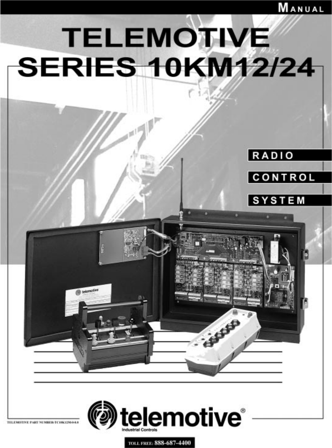
Telemotive Controls E13653-JLTX Industrial Crane Remote Control User Manual 10KM12 24

Telemotive Industrial Controls Industrial Crane Remote Control 10KM12 24

Manual

Table of ContentsiSection 1 - Service Information Heading  . . . . . . . . . . . . . . . . . . . . . . . . . . . . . . . . . . . . . . . . . . . . . . . . . . . . . . . . . . . . . . . . . 1-11-1. Service Information . . . . . . . . . . . . . . . . . . . . . . . . . . . . . . . . . . . . . . . . . . . . . . . . . . . . . . . . . . . . . . . . . . . . . 1-1Section 2 - Radio Controlled Crane Safety . . . . . . . . . . . . . . . . . . . . . . . . . . . . . . . . . . . . . . . . . . . . . . . . . . . . . . . . . . . . . . . . 2-12-1. Introduction  . . . . . . . . . . . . . . . . . . . . . . . . . . . . . . . . . . . . . . . . . . . . . . . . . . . . . . . . . . . . . . . . . . . . . . . . . . . 2-12-2. General . . . . . . . . . . . . . . . . . . . . . . . . . . . . . . . . . . . . . . . . . . . . . . . . . . . . . . . . . . . . . . . . . . . . . . . . . . . . . . . 2-12-3. Persons Authorized To Operate Radio Controlled Cranes. . . . . . . . . . . . . . . . . . . . . . . . . . . . . . . . . . . . . . . . 2-12-4. Training Checklist For Crane Operators  . . . . . . . . . . . . . . . . . . . . . . . . . . . . . . . . . . . . . . . . . . . . . . . . . . . . . 2-12-5. Operating Area . . . . . . . . . . . . . . . . . . . . . . . . . . . . . . . . . . . . . . . . . . . . . . . . . . . . . . . . . . . . . . . . . . . . . . . . . 2-12-6. Transmitter Unit . . . . . . . . . . . . . . . . . . . . . . . . . . . . . . . . . . . . . . . . . . . . . . . . . . . . . . . . . . . . . . . . . . . . . . . . 2-12-7. Operating The Crane  . . . . . . . . . . . . . . . . . . . . . . . . . . . . . . . . . . . . . . . . . . . . . . . . . . . . . . . . . . . . . . . . . . . . 2-22-8. Boarding The Crane . . . . . . . . . . . . . . . . . . . . . . . . . . . . . . . . . . . . . . . . . . . . . . . . . . . . . . . . . . . . . . . . . . . . . 2-32-9. Crane Repair. . . . . . . . . . . . . . . . . . . . . . . . . . . . . . . . . . . . . . . . . . . . . . . . . . . . . . . . . . . . . . . . . . . . . . . . . . . 2-32-10. Using The Crane As a Work Platform . . . . . . . . . . . . . . . . . . . . . . . . . . . . . . . . . . . . . . . . . . . . . . . . . . . . . . 2-32-11. Condition Of The Radio Controlled Crane  . . . . . . . . . . . . . . . . . . . . . . . . . . . . . . . . . . . . . . . . . . . . . . . . . . 2-42-12. Battery Disposal . . . . . . . . . . . . . . . . . . . . . . . . . . . . . . . . . . . . . . . . . . . . . . . . . . . . . . . . . . . . . . . . . . . . . . . 2-4Section 3 - General System Information . . . . . . . . . . . . . . . . . . . . . . . . . . . . . . . . . . . . . . . . . . . . . . . . . . . . . . . . . . . . . . . . . . 3-13-1. General System Information  . . . . . . . . . . . . . . . . . . . . . . . . . . . . . . . . . . . . . . . . . . . . . . . . . . . . . . . . . . . . . . 3-13-2. Transmitter Unit . . . . . . . . . . . . . . . . . . . . . . . . . . . . . . . . . . . . . . . . . . . . . . . . . . . . . . . . . . . . . . . . . . . . . . . . 3-13-3. Receiver Unit . . . . . . . . . . . . . . . . . . . . . . . . . . . . . . . . . . . . . . . . . . . . . . . . . . . . . . . . . . . . . . . . . . . . . . . . . . 3-13-4. System Specifications. . . . . . . . . . . . . . . . . . . . . . . . . . . . . . . . . . . . . . . . . . . . . . . . . . . . . . . . . . . . . . . . . . . . 3-13-5. Time Multiplex Shared (TMS) System Software. . . . . . . . . . . . . . . . . . . . . . . . . . . . . . . . . . . . . . . . . . . . . . . 3-1Section 4 - Installation Information. . . . . . . . . . . . . . . . . . . . . . . . . . . . . . . . . . . . . . . . . . . . . . . . . . . . . . . . . . . . . . . . . . . . . . 4-14-1. Pre-Installation Considerations  . . . . . . . . . . . . . . . . . . . . . . . . . . . . . . . . . . . . . . . . . . . . . . . . . . . . . . . . . . . . 4-14-2. Receiver Unit Mounting Location Considerations. . . . . . . . . . . . . . . . . . . . . . . . . . . . . . . . . . . . . . . . . . . . . . 4-14-3. Line Input Considerations  . . . . . . . . . . . . . . . . . . . . . . . . . . . . . . . . . . . . . . . . . . . . . . . . . . . . . . . . . . . . . . . . 4-14-4. EZ Setup. . . . . . . . . . . . . . . . . . . . . . . . . . . . . . . . . . . . . . . . . . . . . . . . . . . . . . . . . . . . . . . . . . . . . . . . . . . . . .4-14-5. Receiver Unit Cabinet Mounting . . . . . . . . . . . . . . . . . . . . . . . . . . . . . . . . . . . . . . . . . . . . . . . . . . . . . . . . . . . 4-14-6. Receiver Installation. . . . . . . . . . . . . . . . . . . . . . . . . . . . . . . . . . . . . . . . . . . . . . . . . . . . . . . . . . . . . . . . . . . . . 4-14-7. Special Receiver Functions  . . . . . . . . . . . . . . . . . . . . . . . . . . . . . . . . . . . . . . . . . . . . . . . . . . . . . . . . . . . . . . . 4-24-7.1. Master Control Relay (MCR) Enable (S1) . . . . . . . . . . . . . . . . . . . . . . . . . . . . . . . . . . . . . . . . . 4-24-7.2. Auxiliary Functions General. . . . . . . . . . . . . . . . . . . . . . . . . . . . . . . . . . . . . . . . . . . . . . . . . . . . 4-24-7.3. System Functions Selection  . . . . . . . . . . . . . . . . . . . . . . . . . . . . . . . . . . . . . . . . . . . . . . . . . . . . 4-44-7.4. Auto Alarm and EMS Alarm  . . . . . . . . . . . . . . . . . . . . . . . . . . . . . . . . . . . . . . . . . . . . . . . . . . . 4-44-7.4.1. Auto Alarm (S2-1) . . . . . . . . . . . . . . . . . . . . . . . . . . . . . . . . . . . . . . . . . . . . . . . . . 4-44-7.4.1.1. Description  . . . . . . . . . . . . . . . . . . . . . . . . . . . . . . . . . . . . . . . . . . . . 4-44-7.4.1.2. To Enable. . . . . . . . . . . . . . . . . . . . . . . . . . . . . . . . . . . . . . . . . . . . . . 4-44-7.4.2. Emergency Stop (EMS) Alarm (S2-2) . . . . . . . . . . . . . . . . . . . . . . . . . . . . . . . . . . 4-44-7.4.2.1. Description  . . . . . . . . . . . . . . . . . . . . . . . . . . . . . . . . . . . . . . . . . . . . 4-44-7.4.2.2. To Enable. . . . . . . . . . . . . . . . . . . . . . . . . . . . . . . . . . . . . . . . . . . . . . 4-44-7.5. Master Control Relay (MCR) Monitoring Disable (S2-3) . . . . . . . . . . . . . . . . . . . . . . . . . . . . . 4-44-7.6. Auxiliary Function Relay Latching. . . . . . . . . . . . . . . . . . . . . . . . . . . . . . . . . . . . . . . . . . . . . . . 4-44-7.7. Time Out Timer Enable (S3-2) . . . . . . . . . . . . . . . . . . . . . . . . . . . . . . . . . . . . . . . . . . . . . . . . . . 4-44-7.8. Multibox Enable (S3-3). . . . . . . . . . . . . . . . . . . . . . . . . . . . . . . . . . . . . . . . . . . . . . . . . . . . . . . . 4-4Section 5 - Troubleshooting. . . . . . . . . . . . . . . . . . . . . . . . . . . . . . . . . . . . . . . . . . . . . . . . . . . . . . . . . . . . . . . . . . . . . . . . . . . . 5-15-1. Diagnostic Led's. . . . . . . . . . . . . . . . . . . . . . . . . . . . . . . . . . . . . . . . . . . . . . . . . . . . . . . . . . . . . . . . . . . . . . . . 5-15-1.1. Microprocessor Control Module . . . . . . . . . . . . . . . . . . . . . . . . . . . . . . . . . . . . . . . . . . . . . . . . . 5-15-1.2. Power Supply Module. . . . . . . . . . . . . . . . . . . . . . . . . . . . . . . . . . . . . . . . . . . . . . . . . . . . . . . . . 5-35-1.3. Relay and Output Modules . . . . . . . . . . . . . . . . . . . . . . . . . . . . . . . . . . . . . . . . . . . . . . . . . . . . . 5-35-2. Output Module Testing. . . . . . . . . . . . . . . . . . . . . . . . . . . . . . . . . . . . . . . . . . . . . . . . . . . . . . . . . . . . . . . . . . . 5-3
Table of Contents (continued)iiSection 6 - Programming and Servicing Information. . . . . . . . . . . . . . . . . . . . . . . . . . . . . . . . . . . . . . . . . . . . . . . . . . . . . . . . 6-16-1. 10KM Receiver CPU Board Programming and Servicing Information . . . . . . . . . . . . . . . . . . . . . . . . . . . . . 6-16-1.1. S1 Switch Settings  . . . . . . . . . . . . . . . . . . . . . . . . . . . . . . . . . . . . . . . . . . . . . . . . . . . . . . . . . . . 6-16-1.2. S2 Switch Settings  . . . . . . . . . . . . . . . . . . . . . . . . . . . . . . . . . . . . . . . . . . . . . . . . . . . . . . . . . . . 6-16-1.3. JU2 Jumper Settings . . . . . . . . . . . . . . . . . . . . . . . . . . . . . . . . . . . . . . . . . . . . . . . . . . . . . . . . . . 6-16-1.4. S3 Switch Settings  . . . . . . . . . . . . . . . . . . . . . . . . . . . . . . . . . . . . . . . . . . . . . . . . . . . . . . . . . . . 6-16-1.5. S3 Multibox Setting . . . . . . . . . . . . . . . . . . . . . . . . . . . . . . . . . . . . . . . . . . . . . . . . . . . . . . . . . . 6-16-2. Pendant Transmitter Board Programming and Servicing Information . . . . . . . . . . . . . . . . . . . . . . . . . . . . . . 6-26-2.1. Setting Access Code . . . . . . . . . . . . . . . . . . . . . . . . . . . . . . . . . . . . . . . . . . . . . . . . . . . . . . . . . . 6-26-2.2. To Check Data  . . . . . . . . . . . . . . . . . . . . . . . . . . . . . . . . . . . . . . . . . . . . . . . . . . . . . . . . . . . . . . 6-26-2.3. Battery Monitor Adjustment. . . . . . . . . . . . . . . . . . . . . . . . . . . . . . . . . . . . . . . . . . . . . . . . . . . . 6-26-3. Membrane Transmitter Board Programming and Servicing Information . . . . . . . . . . . . . . . . . . . . . . . . . . . . 6-36-3.1. Setting Access Code . . . . . . . . . . . . . . . . . . . . . . . . . . . . . . . . . . . . . . . . . . . . . . . . . . . . . . . . . . 6-36-3.2. To Check Data  . . . . . . . . . . . . . . . . . . . . . . . . . . . . . . . . . . . . . . . . . . . . . . . . . . . . . . . . . . . . . . 6-36-3.3. Battery Monitor Adjustment. . . . . . . . . . . . . . . . . . . . . . . . . . . . . . . . . . . . . . . . . . . . . . . . . . . . 6-36-4. SLTX Transmitter Board Programming and Servicing Information . . . . . . . . . . . . . . . . . . . . . . . . . . . . . . . . 6-46-4.1. Setting Access Code . . . . . . . . . . . . . . . . . . . . . . . . . . . . . . . . . . . . . . . . . . . . . . . . . . . . . . . . . . 6-46-4.2. To Check Data  . . . . . . . . . . . . . . . . . . . . . . . . . . . . . . . . . . . . . . . . . . . . . . . . . . . . . . . . . . . . . . 6-46-4.3. Battery Monitor Adjustment. . . . . . . . . . . . . . . . . . . . . . . . . . . . . . . . . . . . . . . . . . . . . . . . . . . . 6-46-5. Membrane Transmitter Mode Select . . . . . . . . . . . . . . . . . . . . . . . . . . . . . . . . . . . . . . . . . . . . . . . . . . . . . . . . 6-5Section 7 - Spare Parts  . . . . . . . . . . . . . . . . . . . . . . . . . . . . . . . . . . . . . . . . . . . . . . . . . . . . . . . . . . . . . . . . . . . . . . . . . . . . . . . 7-17-1. 10K Receiver Spare Parts  . . . . . . . . . . . . . . . . . . . . . . . . . . . . . . . . . . . . . . . . . . . . . . . . . . . . . . . . . . . . . . . . 7-17-2. 10K Pendant Transmitter Parts  . . . . . . . . . . . . . . . . . . . . . . . . . . . . . . . . . . . . . . . . . . . . . . . . . . . . . . . . . . . . 7-27-3. Membrane Transmitter Unit Spare Parts . . . . . . . . . . . . . . . . . . . . . . . . . . . . . . . . . . . . . . . . . . . . . . . . . . . . . 7-37-4. Small Lever Transmitter Unit Spare Parts. . . . . . . . . . . . . . . . . . . . . . . . . . . . . . . . . . . . . . . . . . . . . . . . . . . . 7-4Section 8 - Transmitter Operation. . . . . . . . . . . . . . . . . . . . . . . . . . . . . . . . . . . . . . . . . . . . . . . . . . . . . . . . . . . . . . . . . . . . . . . 8-18-1. Power On/Off Push-Button . . . . . . . . . . . . . . . . . . . . . . . . . . . . . . . . . . . . . . . . . . . . . . . . . . . . . . . . . . . . . . . 8-18-2. E-Stop  . . . . . . . . . . . . . . . . . . . . . . . . . . . . . . . . . . . . . . . . . . . . . . . . . . . . . . . . . . . . . . . . . . . . . . . . . . . . . . . 8-18-3. Motion Push Buttons, Joysticks Or Levers . . . . . . . . . . . . . . . . . . . . . . . . . . . . . . . . . . . . . . . . . . . . . . . . . . . 8-18-4. Transmitter LED Indicator. . . . . . . . . . . . . . . . . . . . . . . . . . . . . . . . . . . . . . . . . . . . . . . . . . . . . . . . . . . . . . . . 8-18-5. Time-Out-Timer. . . . . . . . . . . . . . . . . . . . . . . . . . . . . . . . . . . . . . . . . . . . . . . . . . . . . . . . . . . . . . . . . . . . . . . . 8-18-6. Key Switch. . . . . . . . . . . . . . . . . . . . . . . . . . . . . . . . . . . . . . . . . . . . . . . . . . . . . . . . . . . . . . . . . . . . . . . . . . . . 8-18-7. Servicing Information . . . . . . . . . . . . . . . . . . . . . . . . . . . . . . . . . . . . . . . . . . . . . . . . . . . . . . . . . . . . . . . . . . . 8-1Appendix A - 10K12/18 Pendant and SLTX Transmitter Programming . . . . . . . . . . . . . . . . . . . . . . . . . . . . . . . . . . . . . . . . .A-1A-1. Transmitter Switches Sw3 and Sw4 Programming. . . . . . . . . . . . . . . . . . . . . . . . . . . . . . . . . . . . . . . . . . . . .A-2A-1.1. Transmitter programming Sw3  . . . . . . . . . . . . . . . . . . . . . . . . . . . . . . . . . . . . . . . . . . . . . . . . .A-2A-1.1.1. Positions 1-3 (Pendant only) Switch Positioning . . . . . . . . . . . . . . . . . . . . . . . . .A-2A-1.1.2. Positions 1-3 (SLTX only) no function. . . . . . . . . . . . . . . . . . . . . . . . . . . . . . . . .A-2A-1.1.3. Positions 4-7 no function  . . . . . . . . . . . . . . . . . . . . . . . . . . . . . . . . . . . . . . . . . . .A-2A-1.1.4. Position 8 Time-out-timer Disable . . . . . . . . . . . . . . . . . . . . . . . . . . . . . . . . . . . .A-2A-1.2. Transmitter programming Sw4  . . . . . . . . . . . . . . . . . . . . . . . . . . . . . . . . . . . . . . . . . . . . . . . . .A-2A-1.2.1. Position 1-2 Mode Enable. . . . . . . . . . . . . . . . . . . . . . . . . . . . . . . . . . . . . . . . . . .A-2A-1.2.2. Position 3 Disable Tandem for hoist and trolley. . . . . . . . . . . . . . . . . . . . . . . . . .A-2A-1.2.3. Position 4 Invert Crane Select Aux. Outputs . . . . . . . . . . . . . . . . . . . . . . . . . . . .A-2A-1.2.4. Positions 5-7 Extended Crane Control Configurations. . . . . . . . . . . . . . . . . . . . .A-2A-1.2.5. Position 8 no function. . . . . . . . . . . . . . . . . . . . . . . . . . . . . . . . . . . . . . . . . . . . . .A-2A-2. Replacement Transmitter EPROM’s. . . . . . . . . . . . . . . . . . . . . . . . . . . . . . . . . . . . . . . . . . . . . . . . . . . . . . . .A-3A-3. Multibox and Optional Output Board. . . . . . . . . . . . . . . . . . . . . . . . . . . . . . . . . . . . . . . . . . . . . . . . . . . . . . .A-3A-4. Latching of Auxiliary Relays . . . . . . . . . . . . . . . . . . . . . . . . . . . . . . . . . . . . . . . . . . . . . . . . . . . . . . . . . . . . .A-3A-5. Tables 1(a) through (k) Wiring and Programming Diagrams. . . . . . . . . . . . . . . . . . . . . . . . . . . . . . . . . . . . .A-4A-6. Optional 120 Volt Wiring . . . . . . . . . . . . . . . . . . . . . . . . . . . . . . . . . . . . . . . . . . . . . . . . . . . . . . . . . . . . . . . .A-4A-7. Crane Control Type Selection. . . . . . . . . . . . . . . . . . . . . . . . . . . . . . . . . . . . . . . . . . . . . . . . . . . . . . . . . . . . .A-5
Table of Contents (continued)iiiAppendix B - 10K12 2-Speed Membrane Transmitter Programming. . . . . . . . . . . . . . . . . . . . . . . . . . . . . . . . . . . . . . . . . . . .B-1B-1. Transmitter Switches Sw3 and Sw4 Programming . . . . . . . . . . . . . . . . . . . . . . . . . . . . . . . . . . . . . . . . . . . . .B-2B-1.1. Transmitter programming Sw3. . . . . . . . . . . . . . . . . . . . . . . . . . . . . . . . . . . . . . . . . . . . . . . . . .B-2B-1.1.1. Positions 1-3 Switch Positioning. . . . . . . . . . . . . . . . . . . . . . . . . . . . . . . . . . . . . .B-2B-1.1.2. Position 4 Time-out-timer Disable  . . . . . . . . . . . . . . . . . . . . . . . . . . . . . . . . . . . .B-2B-1.1.3. Positions 5-7 Extended Crane Control Configurations . . . . . . . . . . . . . . . . . . . . .B-2B-1.1.4. Position 8 no function . . . . . . . . . . . . . . . . . . . . . . . . . . . . . . . . . . . . . . . . . . . . . .B-2B-1.2. Transmitter programming Sw4. . . . . . . . . . . . . . . . . . . . . . . . . . . . . . . . . . . . . . . . . . . . . . . . . .B-2B-1.2.1. Positions 1-2 Mode Enable . . . . . . . . . . . . . . . . . . . . . . . . . . . . . . . . . . . . . . . . . .B-2B-2. Replacement Transmitter EPROM’s . . . . . . . . . . . . . . . . . . . . . . . . . . . . . . . . . . . . . . . . . . . . . . . . . . . . . . . .B-3B-3. Multibox and Optional Output Board . . . . . . . . . . . . . . . . . . . . . . . . . . . . . . . . . . . . . . . . . . . . . . . . . . . . . . .B-3B-4. Latching of Auxiliary Relays. . . . . . . . . . . . . . . . . . . . . . . . . . . . . . . . . . . . . . . . . . . . . . . . . . . . . . . . . . . . . .B-3B-5. TABLE 1(a) through TABLE 1(g) Wiring and Programming Diagrams  . . . . . . . . . . . . . . . . . . . . . . . . . . . .B-3B-6. Optional 110 Volt Wiring. . . . . . . . . . . . . . . . . . . . . . . . . . . . . . . . . . . . . . . . . . . . . . . . . . . . . . . . . . . . . . . . .B-4B-7. Crane Control Type Selection . . . . . . . . . . . . . . . . . . . . . . . . . . . . . . . . . . . . . . . . . . . . . . . . . . . . . . . . . . . . .B-5Appendix C - 10K16/24 Pendant and SLTX Transmitter Programming. . . . . . . . . . . . . . . . . . . . . . . . . . . . . . . . . . . . . . . . . .C-1C-1. Transmitter Switches Sw3 and Sw4 Programming . . . . . . . . . . . . . . . . . . . . . . . . . . . . . . . . . . . . . . . . . . . . .C-2C-1.1. Transmitter programming Sw3. . . . . . . . . . . . . . . . . . . . . . . . . . . . . . . . . . . . . . . . . . . . . . . . . .C-2C-1.1.1. Positions 1-3 (Pendant only) Switch Positioning  . . . . . . . . . . . . . . . . . . . . . . . . .C-2C-1.1.2. Positions 1-3 (SLTX only) no function . . . . . . . . . . . . . . . . . . . . . . . . . . . . . . . . .C-2C-1.1.3. Positions 4-7 no function. . . . . . . . . . . . . . . . . . . . . . . . . . . . . . . . . . . . . . . . . . . .C-2C-1.1.4. Position 8 Time-out-timer Disable  . . . . . . . . . . . . . . . . . . . . . . . . . . . . . . . . . . . .C-2C-1.2. Transmitter programming Sw4. . . . . . . . . . . . . . . . . . . . . . . . . . . . . . . . . . . . . . . . . . . . . . . . . .C-2C-1.2.1. Position 1-2 Mode  Enable  . . . . . . . . . . . . . . . . . . . . . . . . . . . . . . . . . . . . . . . . . .C-2C-1.2.2. Position 3 Disable Tandem for hoist and trolley . . . . . . . . . . . . . . . . . . . . . . . . . .C-2C-1.2.3. Position 4 Invert Crane Select Aux. Outputs. . . . . . . . . . . . . . . . . . . . . . . . . . . . .C-2C-1.2.4. Positions 5-7 Extended Crane Control Configurations . . . . . . . . . . . . . . . . . . . . .C-2C-1.2.5. Position 8 no function . . . . . . . . . . . . . . . . . . . . . . . . . . . . . . . . . . . . . . . . . . . . . .C-2C-2. Replacement Transmitter EPROM’s . . . . . . . . . . . . . . . . . . . . . . . . . . . . . . . . . . . . . . . . . . . . . . . . . . . . . . . .C-3C-3. Multibox and Optional Output Board . . . . . . . . . . . . . . . . . . . . . . . . . . . . . . . . . . . . . . . . . . . . . . . . . . . . . . .C-3C-3.1. 10K16 Only  . . . . . . . . . . . . . . . . . . . . . . . . . . . . . . . . . . . . . . . . . . . . . . . . . . . . . . . . . . . . . . . .C-3C-3.2. 10K24 Only  . . . . . . . . . . . . . . . . . . . . . . . . . . . . . . . . . . . . . . . . . . . . . . . . . . . . . . . . . . . . . . . .C-3C-4. Latching of Auxiliary Relays. . . . . . . . . . . . . . . . . . . . . . . . . . . . . . . . . . . . . . . . . . . . . . . . . . . . . . . . . . . . . .C-3C-5. TABLE 1(a) through TABLE 1(g) Wiring and Programming Diagrams  . . . . . . . . . . . . . . . . . . . . . . . . . . . .C-4C-6. Optional 110 Volt Wiring. . . . . . . . . . . . . . . . . . . . . . . . . . . . . . . . . . . . . . . . . . . . . . . . . . . . . . . . . . . . . . . . .C-4C-7. Crane Control Type Selection . . . . . . . . . . . . . . . . . . . . . . . . . . . . . . . . . . . . . . . . . . . . . . . . . . . . . . . . . . . . .C-5
Table of Contents (continued)ivThis Page Intentionally Left Blank
1-11-1. Service Information.For questions regarding service or technical information,contact the Telemotive Field Service Department.For ordering replacement parts contact the TelemotiveOrder Entry Department. Telemotive Industrial Controls175 Wall StreetGlendale Heights, IL  60139-1985Toll Free: 888-687-4400Telephone: 630-582-1111Website: WWW.telemotive.comTelemotive Fax Numbers:Main: 630-582-1194Sales: 630-582-1204Parts/Service: 630-582-1205Section 1 - Service Information Heading
Section 1 - Service Information (Continued)1-2This Page Intentionally Left Blank
2-12-1. Introduction.The safety rules in this section are not intended to replaceany rules or regulations or any applicable local, state, or fed-eral governing organizations. The following information isintended to be used in conjunction with other rules or regu-lations already in existence. It is important to read all of thesafety information contained in this section before operatingthe Radio Control System.2-2. General.Radio controlled overhead cranes and other material han-dling equipment operate in several directions. They arelarge, bulky pieces of equipment that handle heavy loadsefficiently at high speeds. Quite frequently, the  equipmentis operated in areas where people are working on the floorbelow. Extreme caution must be exercised by the craneoperator at all times. Workers must constantly be alert toavoid accidents. The following rules have been included toindicate how your careful and thoughtful actions may pre-vent injuries, damage to equipment, or even save a life. Ifradio controlled material handling equipment is operatedfrom the cab, special care must be taken to secure the trans-mitter. Refer to paragraph titled "Boarding The Crane" forspecific safety rules.2-3. Persons Authorized To Operate Radio Controlled Cranes.Only properly trained persons designated by managementshould be permitted to operate radio controlled cranes.Radio controlled cranes should not be operated by any per-son who cannot read or understand signs, notices and oper-ating instructions that pertain to the crane.Radio controlled cranes should not be operated by any per-son with insufficient eyesight or hearing or by any personwho may be suffering from a disorder or illness or is takingany medication that may cause loss of crane control.2-4. Training Checklist For Crane Operators.Anyone being trained to operate a radio controlled craneshould possess the following knowledge and skills beforeoperating the crane:Knowledge of hazards peculiar to crane operation.Knowledge of safety rules for radio controlled cranes.Ability to judge distance or moving objects.Knowledge of the radio transmitter.Limit switch test procedure.Where authorized, instructions for plugging motions.Observing crane signal lights.Avoid striking any obstructions.Proper clearance of lifts or hooks before moving bridge ortrolley.Proper storage space for radio control box when not in use.Transferring radio control box to another person.Reporting unsafe or unusual operating conditions.Caution in approaching bridge or trolley bumpers.Equipment capacity.Making lifts below floor level.Making side pulls.Keeping body clear of lifts and avoiding "pinch" points.Cable and hook inspection.Procedures for testing hoist, trolley, and bridge brakes.2-5. Operating Area.Aisles between equipment, stock, etc., should be free ofobstructions so the crane operator can move freely. Theseaisles should be a minimum of 3 feet wide, or meet localregulations.Crane operators should always position themselves for thebest view of the crane they are controlling. The crane shouldnever be operated blindly. The operator should stay as closeto the crane load as possible. Operators should never posi-tion themselves in a "pinch" point.2-6. Transmitter Unit.Transmitter switches should never be mechanically blockedON or OFF for any crane motion. When not in use turn thetransmitter OFF. A secure storage space should be providedfor the transmitter unit and the transmitter unit shouldalways be placed there when not in use. This precaution willprevent unauthorized people from operating the crane.Section 2 - Radio Controlled Crane Safety
Section 2 - Radio Controlled Crane Safety (Continued)2-22-7. Operating The Crane.The crane limit switches should be checked at the beginningof each shift or when a new operator takes control of thecrane. When checking limit switches the hoist should becentered over an area free of personnel and equipment.The limit switches should never be used as a regular stop-ping device. They are intended to be protective devices.The bridge and trolley brakes should be tested at the begin-ning of each shift or when a new operator takes control ofthe crane. On transmitter units equipped with two speeds,use the "low" speed when testing braking devices.When lifting maximum loads, the crane operator should testthe hoist brakes by raising the load a few inches from thefloor. If the brakes do not hold, the load should immediatelybe lowered to the floor and a report made to the supervisor.Do not make lifts in excess of the equipment rated capacity.The bridge and trolley should be centered directly over theload when the load is raised to prevent swinging when mak-ing lifts.Side pulls should be made by a crane designed for this pur-pose and only with supervisor permission. When a lift isbeing made, the crane operator should not be positioned inthe line of travel. The crane or hoist should be operatedfrom a position either to the side or opposite from the direc-tion of travel.When raising or lowering a load, proceed slowly and makecertain the load is under control. Tag lines should be usedfor handling unusual lengths or bulky loads. Remove slackfrom chains or slings gradually. Make certain all personnelare clear before making a lift.The crane operator should keep all body parts away fromthe lift and should never be positioned under the lift.Do not make a lift or move a load if anyone is in a locationwhere they could be struck by the crane or the load.If the crane operator is being helped, the crane should not bemoved until the helper signals they are clear of the craneand its load.When a load is hanging from the crane hook and the crane isbeing moved, the crane operator should sound all warningdevices frequently.Loads should not be carried over workers heads. If a workeris in the path of crane travel, the crane operator should stopthe crane and clear the area before proceeding.Runway stops or other cranes should never be bumped into.When moving the crane, the crane operator should be surethat the hook block and attachments or cables will not catchon nearby equipment. Slings, chains, or cables should neverbe dragged along the floor.Unless required for operator safety, gloves should not beworn when operating the transmitter unit.All loose materials or parts should be removed from theload before starting the lift.The crane operator should always hoist lifts high enough toclear all equipment and workers.The crane operator should never permit anyone to ride onthe load or hook except when authorized by the supervisor.When another crane on the same runway is stationary with aload hanging, the crane operator should maintain a safe dis-tance between the stationary crane and the one under theircontrol.If power to the crane is removed, the crane operator shouldturn the transmitter unit OFF and keep it OFF until power isrestored.If the crane fails to respond properly, the crane operatorshould stop operation, turn the transmitter unit OFF andimmediately report the condition to their supervisor.Outdoor cranes which are subject to movement by windshould be securely anchored when left unattended. If thecrane is equipped with bridge brakes, the parking brakeshould be set immediately.
Section 2 - Radio Controlled Crane Safety (Continued)2-32-8. Boarding The Crane.The crane should not be boarded without permission of thesupervisor.The crane operator should turn off the transmitter and take itwith them when boarding the crane.If more than one person is boarding the crane, one personshould be made responsible for ensuring all personnel areoff the crane before the system is returned to operation.2-9. Crane Repair.Minor repairs include routine maintenance and repairs suchas greasing, cleaning and control troubleshooting. All otherrepairs should be considered major. If the repair crew con-sists of more than one person, one person should be desig-nated as the repair crew leader with the followingresponsibilities. If the repair crew consists of only one per-son, that person has the following responsibilities:Warning signs should be placed on the floor beneath thecrane or suspended from the crane. For major repairs, thefloor area below the crane should be roped off.When major repairs are to take place, all persons operatingother cranes on the same or adjacent runways, if any, mustbe notified prior to starting repairs. Notification shouldinclude the nature of the repair, safeguards provided, andmovement limitations while repairs are in progress.When practical, radio controlled cranes which cannot bemoved during repairs must be protected against beingbumped by other cranes on the runway. Bumpers should beinstalled on the exposed side or sides of the crane underrepair. They should be placed as far away as possible. Thelocation of these bumpers should be indicated by red lightsplaced so that they are clearly visible to other crane opera-tors traveling on the same runway. When it is not possible touse bumpers, red lights must be placed so they are clearlyvisible to other crane operators traveling on the same run-way to indicate the restricted travel zone. All crane opera-tors on the same runway must be informed of the repaireffort and thoroughly instructed to what their operations arelimited to and informed they will be notified when repairsare completed.If any hazard involving the repairmen exists when there is arunway adjacent to the crane under repair, the adjacent run-way should be blocked off as described above. When it isnecessary to continue crane operation on the adjacent run-ways warning lights must be installed and be visible tooperators of cranes on those runways. All cranes shouldcome to a complete stop prior to entering the restricted areaand should proceed through this area only after receivingpermission from a signal person designated for this purpose.Access of persons to and from the crane being repairedshould be under control of the repair crew leader.When boarding the crane, the transmitter should be turnedOFF and the transmitter should remain with the repair crewleader. The leader should board the crane first, open andlock out the main switch, and then signal the other membersof the crew it is safe to board the crane.If work on the crane is to be done in areas not protected bystandard handrails, approved safety belts should be worn bythe repair crew.All tools and equipment should be moved onto the crane bythe use of hand lines. The tools and equipment should beadequately secured to the hand lines.If it is necessary to have the crane control circuits energized,all power circuits for crane movement must be opened priorto energizing the control circuits.All personnel and tools should be moved to a safe spotbefore moving the crane during repairs.Head room is at a minimum in some crane cabs and onsome crane walkways. Caution should be exercised whenboarding or working on cranes. Hard hats should be wornwhenever possible.When repairs are finished, all personnel, tools and repairequipment should be removed before energizing the cranecircuits.2-10. Using The Crane As a Work Platform.When the crane is to be used as a stationary work platform,follow all rules provided in "Crane Repair" section.When it is necessary for the crane to be moved from time totime, the crane operator should board the crane with thetransmitter unit. The crane operator should ensure all per-sonnel working on the crane are in a secure position beforemoving the crane to the next work station. It should also bethe crane operators responsibility to ensure the main switchis open and locked down before work is resumed.
Section 2 - Radio Controlled Crane Safety (Continued)2-4WARNINGTHE CRANE OPERATOR SHOULD NOT ATTEMPT TOMAKE ANY OF THE REPAIRS STATED BELOW.  THECRANE CONDITION SHOULD BE REPORTED TO THESUPERVISOR.2-11. Condition Of The Radio Controlled Crane.If the crane fails to respond properly, the crane operatorshould notify their supervisor. When serious conditions arenoticed (conditions that make the crane unsafe to operate),the crane should be shut down immediately and the supervi-sor notified. The following is a list of what should beincluded in the report:Condition of hoisting cable and hook block (broken strands,clipped sheave wheels, etc.).Condition of brakes (hoist, trolley, and bridge).Alignment of bridge (screeching or squealing wheels indi-cate bridge is out of line).Broken, cracked, or chipped rails on trolley or runway.Condition of limit switches.Condition of electrical and mechanical control (electrical ormechanical defects which cause faulty operation such asuncommanded stopping or starting of any crane motions,warning devices, lights, or auxiliary functions).Condition of gears (grinding or squealing may indicate for-eign materials in gear teeth or a lack of lubrication.Frequent relay tripping of power circuits.Mechanical parts loosened by vibration (loose rivets, cov-ers, bolts, etc.).Uneven riding (worn wheels).Condition of collector shoes or bars.Condition of warning or signal lights (burned out or bro-ken).2-12. Battery Disposal.Consult local requirements for disposal.
3-13-1. General System Information.The Series 10K Radio Control System (system) providesremote control of overhead cranes using radio signals. Thesystem consists of a hand held portable battery operatedtransmitter unit and a fixed station receiver unit.Each system has its own access code which permits areceiver unit to respond only to a transmitter unit with thesame access code. Up to four transmitters may be used withthe same frequency. Each transmitter operating on the samefrequency may be operated in close proximity (not less thansix feet) to each other.Access Code: Any received signal which does not match thereceiver access code is considered invalid by the receiver.3-2. Transmitter Unit.The transmitter unit is frequency modulated, low power andis certified under part 15 of FCC rules and regulations. Alicense is not required for the transmitter or operator. Thetransmitter unit uses crystal controlled oscillators to set theoperating frequency.A power down feature turns the transmitter unit OFF if nokeys are pressed for an extended (approximately 15 min-utes) period of time. The transmitter unit must again beturned ON.  A configuration of the transmitter unit is avail-able without automatic time-out.Battery voltage and data transmission status is provided byan LED mounted on the front panel.3-3. Receiver Unit.The receiver unit consists of an RF receiver module, micro-computer control module, output relay/control modules anda power supply.A power down feature turns the receiver unit OFF if nocommands are received for an extended (approximately 15minutes) period of time. A configuration of the receiver unitis available without automatic time out.3-4. System Specifications.Channel Designations:AK1-439.8 MHz   AK6-438.8 MHzAK2-439.6 MHz   AK7-438.6 MHzAK3-439.4 MHz   AK8-438.4 MHzAK4-439.2 MHz   AK9-438.2 MHzAK5-439.0 MHz   AK10-438.0 MHzAK11-437.8 MHz   AK16-436.8 MHzAK12-437.6 MHz   AK17-436.6 MHzAK13-437.4 MHz   AK18-436.4 MHzAK14-437.2 MHz   AK19-436.2 MHzAK15-437.0 MHz   AK20-436.0 MHzAmbient Operating Conditions - -22°F to +158°F  (-30°C to+70°C)Humidity - up to 95% (non-condensing)Typical Operating Range - 200 feetUp to four transmitter units may operate on the same fre-quency while in close proximity (not less than six feet) toeach other.3-5. Time Multiplex Shared (TMS) System Software.The system software is structured to minimize "on the air"transmission time of any transmitter. This allows for multi-ple transmitters to share a common frequency. The TMSsystem is designed so that a transmitter will send a signalfor a predetermined ON time, and then will turn OFF. Thelength of transmitter ON time is referred to as data burst orpacket. The packet length is a function of the quantity ofdata to be sent, and the data rate (baud). Once the packet issent, the transmitter will turn OFF. This allows for othertransmitters to time share the same frequency when a trans-mitter has turned OFF. The OFF period and repetition rateof the ON period are determined by the TMS system soft-ware. This allows up to 4 transmitters to share and haveequal access to the same frequency, and also allows forreduced battery consumption and extended battery life.Section 3 - General System Information
Section 3 - General System Information (Continued)3-2This Page Intentionally Left Blank
4-14-1. Pre-Installation Considerations.To ensure reliable and safe operation of the system, the fol-lowing items must be considered before installing thereceiver unit.If the receiver unit is installed outdoors or in a corrosiveenvironment, the receiver unit cabinet must be housed in aprotective enclosure.CAUTIONTHE RECEIVER UNIT OR RELAYS ARE NOT RATEDAS EXPLOSION PROOF. THE RECEIVER UNIT MUSTNOT BE INSTALLED IN EXPLOSIVE ENVIRON-MENTS UNLESS APPROPRIATE SECONDARYENCLOSURE MEASURES ARE TAKEN.The receiver unit should not be subjected to moisture.4-2. Receiver Unit Mounting Location Considerations (See Figure 4-2).The receiver unit requires a mounting area of approximately14" wide by 18" long. A depth of at least 18" must be pro-vided to allow the cabinet door to open.Ensure the mounting location is as far as possible fromexposed trolley wires and sources of electromagnetic orradiated noise.If possible, avoid installing receiver unit to a surface wherehigh vibration or shock is present. If this can not be avoided,use appropriate shock mounts.4-3. Line Input Considerations.WARNINGTHE UNIT MUST BE WIRED TO THE CORRECTVOLTAGE,  FAILURE TO DO SO MAY DAMAGE THESYSTEM.The receiver unit has direct and separate connect provisionsfor operation from 120 or 240 VAC (nominal), 50-60 Hzpower.For applications where line voltage deviation exceeds 20%of nominal values or if 440 VAC power is used, a step up orstep down transformer must be used.NOTEThe receiver unit should not be connected to lines contain-ing excessive power up transients or continuous commuta-tor noise. A line conditioner may be necessary in someinstallations.4-4. EZ Setup1. Determine the type of transmitter you have with yourunit.  SLTX, membrane or pendant as shown in Figure4-1.  (For custom or special transmitter refer to customdocumentation).2. Refer to Appendix A, Appendix B, or Appendix C andselect the wiring configuration that matches yourapplication.3. Refer to the transmitter switch programming table atthe bottom of the page for the selected configuration.4. If necessary, open the transmitter and set the switchesas shown in the configuration diagram. Normally youunit is pre-programmed at the factory and only installa-tion is necessary. The programming information for thetransmitter and receiver is only needed for systemspurchased un-programmed or to change system pro-gramming. Switch locations are in Section 6. DO NOTCHANGE SWITCH SW1 OR SW2. These switchesprogram the access code and must be programmed tomatch the receiver. After setting these switches reas-semble the transmitter. Make sure fully charged batter-ies are placed in the unit.5. Determine if you need to special program the receiver.NORMALLY YOU WILL NOT NEED TO CHANGERECEIVER SWITCH SETTINGS.  Change thereceiver settings only to add latched functions, multibox or alarm settings.  For information on theses set-tings see page 6-1.6. Go to paragraph 4-5 Receiver Unit Cabinet Mounting.4-5. Receiver Unit Cabinet Mounting.Recommended mounting hardware is four - 1/4-20 hexmachine screws of appropriate length, four 1/4-20 x 7/16"keps" or elastic stop nuts.Flat washers should be used in front of nuts when receiverunit is mounted to a non structural surface.Mount receiver unit cabinet securely to mounting surface.4-6. Receiver Installation (See Figure 4-2).1. Mounting area, approximately 14" wide by 18" long.2. Ensure mounting location is as far as possible fromexposed Trolley wire and sources of electromagneticor radiated noise.  Antenna should be pointed straightup.3. Mount unit and install antenna.4. Set switch SW1 on power supply to off positiontowards right of cabinet.  Set switch SW1 on computermodule to the left to disable radio outputs.Section 4 - Installation Information
Section 4 - Installation Information (Continued)4-2SLTX MEMBRANE PENDANTFigure 4-1. Tranmitter Type5. Connect power leads to right lower terminal strip J1 onpower supply board to either 120 and ground or 240and ground. See page 6-1.6. Use Appendix A, Appendix B or Appendix C and picka diagram that fits the interface.  All control wiring forthe interface should be connected at terminals to J2 onrelay output board. Note: J3 terminal block is prewiredfor single common control transformer.  When usingmore than one control transformer the jumpers on J3must be removed and J3 should be wired for the propervoltage per terminal.7. In the lower right side of the receiver cabinet on thepower supply board you will find relay K1 (MR).  Ter-minals 2 and 4 are used to control any master relayfunction of the control. Relay K1 is shown in the wir-ing diagrams in Appendix A, Appendix B and Appen-dix C.8. Wiring of the 10K system should now be complete.9. Apply power.10. Check out radio functions with the outputs disabled.Light DS3 should be out at this time.  After the check,put S1 back to the on position DS3 should light.  Checkfunction and direction by jogging each motion.  Instal-lation should now be complete.4-7. Special Receiver Functions.4-7.1. Master Control Relay (MCR) Enable (S1)This switch, when turned to off, disables the MCR andremoves all output power to all output relays.  This allowstesting of the receiver control circuitry without activatingany external functions such as motors and horns. 4-7.2. Auxiliary Functions GeneralThe 10K receivers have auxiliary (Aux) function capability.These Aux functions are dedicated relays that can be used tosound horns, light lights or other functions.  Typically a10K12 has 3 Aux functions and a 10K16/24 has 4.  How-ever, there are a number of specialties and variations avail-able.  If your transmitter does not have a documentdescribing these functions, the easiest way to determinewhat the Aux functions do is to look at the relay controlboards and while depressing the appropriate Aux switch onthe transmitter see which LED lights for which relay.WARNINGMAKE SURE S1 MASTER CONTROL RELAY (MCR) ISTURNED OFF BEFORE ATTEMPTING THIS TO PRE-VENT ACTIVATION OF EXTERNAL CIRCUITRY. SEEPAGE 6-1.AU X 1AU X 2AC CE SS C OD E AU X 3AU X 4SO UT H WEST DO W NONOF FBATT ER YM ON ITORON -OFFKEYEA ST UPNOR THBR IDGE TR OL LEY HO ISTH1 H2SE LECT EM SBOFF -ONOFF -ONOFF -ONH2/T2H1/T1H3/T3ON /OFF EM SHO ISTDIR1HO ISTDIR2TRO LLEYTRO LLEYDIR1DIR2BRIDG EDIR1BRIDG EDIR2UP DNE WN S1 23ESTOPON OFF
Section 4 - Installation Information (Continued)4-3Figure 4-2. Receiver Mounting
Section 4 - Installation Information (Continued)4-44-7.3. System Functions SelectionSpecial programming exists to allow some of the Aux relaysto be dedicated for special system functions.  Setting certaindip switches on the CPU Board enables this programming.4-7.4. Auto Alarm and EMS AlarmYou can have either one of these functions or both.  The useof either one of these two functions dedicates one specificcontrol relay to operate an external alarm.  An externalalarm (not supplied) needs to be connected to this relay.4-7.4.1. Auto Alarm (S2-1)4-7.4.1.1. DescriptionGives about 5 seconds of alarm when the transmitter is firstturned on.4-7.4.1.2. To EnableConnect an external alarm.  Move dip switch S2-1on theCPU Board to the ON position.  See page 6-1 for switchdetails and for location of the Alarm Relay. See the appro-priate wiring diagram in Appendix A, Appendix B orAppendix C.4-7.4.2. Emergency Stop (EMS) Alarm (S2-2)4-7.4.2.1. DescriptionGives about 5 seconds of alarm when the Emergency Stop(EMS) is activated on the transmitter.4-7.4.2.2. To EnableConnect an external alarm.  Move dip switch S2-2 on theCPU Board to the ON position and set jumper JU2 to theupper position.  (As a safety measure during EMS shutdownall control lines to relays are disabled.  Jumper JU2 facili-tates bypassing the EMS shutdown to the Alarm Relay so itcan be activated during an EMS shutdown.)  See page6-1 for switch and jumper details and for location of theAlarm Relay. See the appropriate wiring digram in Appen-dix A, Appendix B or Appendix C.4-7.5. Master Control Relay (MCR) Monitoring Disable (S2-3)Disables the contact monitoring of the MCR.  Used for spe-cial diagnostic purposes only.  In normal operation switchS2-3 should be set to OFF.  Set to ON to disable contactmonitoring of MCR.4-7.6. Auxiliary Function Relay Latching(S2-6, -7 and -8)Enables the appropriate auxiliary function relay to operatein a latched mode, on or off, rather than as a momentarycontact.  Which function is latchable and which relay islatched depends on the particular transmitter used.Switch S2, positions 6 through 8 on the CPU Board eachenable a separate relay to be latched when turned on. If yourtransmitter does not have a document describing these func-tions, the easiest way to determine correlation of transmitterfunction, relay position and dip switch position, is to tryvarious dip switch setting and see which relays are latchedand which transmitter controls them.  Make sure all threeswitch positions are off, turn S2-6, S2-7 and S2-8 on sepa-rately and note which relay is affected by the appropriateLED indication.WARNINGMAKE SURE S1 MASTER CONTROL RELAY (MCR) ISTURNED OFF BEFORE ATTEMPTING THIS TO PRE-VENT ACTIVATION OF EXTERNAL CIRCUITRY.4-7.7. Time Out Timer Enable (S3-2)The receiver contains a time out timer.  If a receiver onceturned on by a transmitter does not receive a signal from atransmitter for a period of 15 minutes the receiver shutsdown.  Setting S3-2 to ON disables this function.4-7.8. Multibox Enable (S3-3)One transmitter can only control the 10K receiver with aspecific access code at a time.  However, Multibox capabil-ity allows the 10K receiver to automatically switch to a newtransmitter when the current controlling transmitter hasbeen turned off and a new transmitter turned on.  Up to 4different transmitters can control one receiver.  To enablethis function the receiver must be preprogrammed from thefactory for Multibox; the appropriate Multibox dip switchenabled (S3-3) and the correct access codes must be pro-grammed into the appropriate transmitters.  (Note:  accesscodes are factory programmed into the receiver and theaccess codes are sequential.).  Switch S3-3, when turned on,enables Multibox.  Turning off S3-3 in 10K receiver pre-programmed from the factory for Multibox disables thisfunction.  S3-3 has no function in a receiver that is not pre-programmed by the factory for Multibox. For specific pro-gramming information see page 6-1.
5-15-1. Diagnostic Led's.Series 10K12/24M (see page 6-1)5-1.1. Microprocessor Control ModuleThe function of each LED is described in Table 5-1.Table 5-1. Diagnostic LED FunctionLED COLOR FUNCTIONDS1 Green Monitors the 12 VDC power to the Microprocessor Control Board.Normally ON.If 12 VDC power is present then LED is illuminated.  LED is off if 12 VDC power is not present. Check power supply, fuses and if power is on to receiver.DS2 Green Monitors + 5 VDC regulated voltage.Normally ON.If 5 VDC power is present then LED is illuminated.  LED is off if 5 VDC power is not present.  Check connectors, the +5 VDC regulator, or for shorts on the board.DS3 Red Monitors closure of the Master Control Relay (MCR) relay (K1).LED will be illuminated when the MCR relay has been enabled by an ON command recieved from the Transmitter Unit.  Led will extinguish, when an OFF command has been transmitted, an EMS condition is present, or SW1 is set to 0.The MCR controls the 12 VDC power to the Master Relay on the Power Supply Board.DS4 Yellow Monitors closure of the Security Relay output (K2).The LED will be illuminated when the Security Relay has been enabled by an ON command received from the Transmitter Unit.  LED will extinguish when an OFF command is transmitted, or an EMS condition is present.The Security Relay controls the 12 VDC power to the MCR relay (K2) and the power to the coils of the control relays (K1 through K8) on the Relay Output Modules.DS5 Yellow Monitors the AC bias pump line for the Security Relay (K2).LED will flash only when the Receiver has been enabled by an ON command.The Security Relay is enabled by an AC signal generated by the slave microcomputer.  The AC signal is capacitively isolated from the slave microcomputer to help prevent the Security Relay from being latched ON if the slave microcomputer fails.  LED will not be illuminated when an OFF command has been sent or an EMS condition is present.DS6 Yellow Monitors AC bias pump line for the Master Control Relay (K1).LED will flash only when the Receiver Interface Control Module has been enabled by an ON command.The Master Control Relay (K1) is enabled by an AC signal generated by the slave microcomputer.  The AC signal is capacitively isolated from the slave microcomputer to help prevent the MCR from being latched ON if the slave microcomputer fails.  The LED will not be illuminated when an OFF command has been sent or is in an EMS mode.DS7 Yellow Monitors data synchronization.  (Flashes when a properly formatted data signal is received from the transmitter).This LED will flash rapidly when data is transmitted.  The LED can be used with DS9 to analyze incoming data.  If DS9 is illuminated or flashing when DS7 also is flashing, another Transmitter Unit on the same frequency may be present.  This is normal.  As more Transmitter Units operated on the same frequency, LED will flash brighter and more often.Section 5 - Troubleshooting
Section 5 - Troubleshooting (Continued)5-2Table 5-1. Diagnostic LED Function (Continued)LED COLOR FUNCTIONDS8 Yellow Monitors continuity between receiver and CPU modules.Normally ON.Off indicates a malfunctioning receiver.DS9 Red Monitors received data errors.Normally OFF.A flashing LED during data transmission may indicate interference of the received data.  If LED is illuminated continuously when data is transmitted and the system will not respond the Access Code of the Receiver and Transmitter Units may not match.  If LED is illuminated when data is not transmitted, another Transmitter Unit may be present on the same frequency with a different Access Code.  The presence of activity on this LED does not necessarily indicate a problem. It should be used with other indicators in analyzing system status.DS10 Yellow Monitors system acitivty.Normally FLASHING.If not flashing the microprocessor is dead.DS11 Red Monitors the ON command from the Transmitter.LED will flash when an ON command is being received from the Transmitter.While pushing the ON button on the Transmitter this should light.DS12 Red Monitors the OFF command from the Transmitter.LED will flash when an OFF command is being received from the Transmitter Unit.While pushing the OFF button on the Transmitter this should light.DS13 Red Monitors EMS condition.Normally OFF.LED will flash when an EMS command is transmitted and illuminate continuously when the EMS condition is in effect.  An EMS condition may be created when an EMS command is transmitted or when a failure mode is detected by the slave microcomputer.  If both DS11 and DS13 are illuminated, a contact monitoring error has been detected.  If both DS9 and DS13 are illuminated, the incoming data on the ICC bus has been corrupted.DS14 Yellow Monitors the AC activity for the Security Relay (K1).Normally ON.If the system is ON and the light is not lit there is a serious microprocessor error.DS15 Red Monitors the watchdog timer.Normally OFF.The LED will illuminate momentarily when power is applied to or removed from the system.  If the LED is continuously flashing or on, the computer is not working properly.  If LED is illuminated constantly (no flashing), the +5 VDC is probably too low.  This could be caused by shorts on the board or by a defective voltage regulator.  If the LED flashes at a constant rate, the microcomputer chip or EPROM may be defective.DS16 Not used.
Section 5 - Troubleshooting (Continued)5-35-1.2. Power Supply ModuleThe function of each LED is described in Table 5-2.Table 5-2. Diagnostic LED Function5-1.3. Relay and Output ModulesThe function of each LED is described in Table 5-3.Table 5-3. Diagnostic LED Function5-2. Output Module Testing.The output module may be tested with a transmitter withoutactivating crane controls by setting SW 1 to off. This allowsthe system to be tested and analyzed without causing move-ment of the crane by removing power to the master relay. LED COLOR FUNCTIONDS1 Green Monitors unregulated 12 VDC.Normally ON.Check fuse, wiring to unit and AC power to unit.DS2 Green Monitors regulated 12 VDC.Normally ON.DS2 off and DS1 on, check for shorts on regulated output or blown regulator.  Disconnect power supply connector to computer control board, if DS2 light comes back on there is a short on one of the other boards.LED COLOR FUNCTIONDS1-6orDS1-8Red Monitors the power to the relay coil or switching device.Normally OFF unless command is sent to turn ON.The numbers of LEDs depend on the number of functions per board.  LEDs are located next to the relay or switch they control.  Ground is switched to the relay coil or switch to turn it on; this also turns on the light.DS7orDS9Yellow Monitors 12 VDC to the relay or output module.Normally ON.LED off indicates no power to the relay or output module.
Section 5 - Troubleshooting (Continued)5-4This Page Intentionally Left Blank
6-16-1. 10KM Receiver CPU Board Programming and Servicing InformationThe receiver CPU board is shown in .  Refer to paragraphs6-1.1 through 6-1.5 for switch and jumper settings..Figure 6-1 Receiver CPU Board Switch and Jumper Locations6-1.1. S1 Switch SettingsControls power to the Master Relay. With the switch set toON power is on to all relays. Move the switch to OFF forcircuit testing without activating external controls.6-1.2. S2 Switch SettingsS2-1 Auto AlarmOFF Auto Alarm DisabledON Auto Alarm EnabledS2-2 EMS AlarmOFF EMS Alarm DisabledON EMS Alarm EnabledS2-3 Master Control RelayOFF MCR DisabledON MCR EnabledS2-4 Not usedS2-5 Not usedS2-6, 7 & 8 Aux Relay Latching*OFF Latching DisabledON Latching Enabled* See the specific configuration for your application fordetails on which switch controls which relay.6-1.3. JU2 Jumper SettingsIn the lower position  (the position shown) the alarm relay isdisabled after an E-Stop shutdown. This is the factorydefault setting.  Moving it to the upper position enables it.See the appropriate Programming Diagram for the AlarmRelay Location.6-1.4. S3 Switch SettingsS3-1 Not usedS3-2 Time Out TimerOFF Time Out EnabledON Time Out DisabledS3-3 MultiboxOFF Multibox DisabledON Multibox EnabledS3-4 10K24 Only*OFF Aux TrolleyON Aux Hoist* Only on the 10K24 with Multibox Enabled. First 4 relayson J6 are Multibox. Last 4 relays on J6 are either Aux Trol-ley or Aux Hoist.S3-5 Not used6-1.5. S3 Multibox Setting (Only with S3-3 On)S3-6 S3-7 S3-8 TXS Access CodeOFF OFF OFF 1 Base AddressOFF OFF ON 2 Base Address +1OFF ON OFF 3 Base Address +2OFFONON4 Base Address +3For more Base Address’ please contact Telemotive.Relay Output Module A Relay Output Module B Relay Output Module CDS-15DS2K1S1ONDS5 DS4 DS1DS3J7 J8 J6Receiver87654321876543210FF 0FFS3 S2Access CodeMembrane      SW2          SW1Pendant          SW1          SW2SLTX             SW1          SW2Toggle            SW2          SW10FF87654321S587654321S4 0FFAccess Code SwitchesDS-7 -8 -9 -10-11-12-13-14J3J4J5JU2J2J1PowerSupplyDiagnostic LEDsK2DS6BAF2 F1Section 6 - Programming and Servicing Information
Section 6 - Programming and Servicing Information (Continued)6-26-2. Pendant Transmitter Board Programming and Servicing InformationThe Pendant Transmitter boards are shown in Figure 6-2.Refer to paragraphs 6-2.1 through 6-2.3 for servicing proce-dures.Figure 6-2. Pendant Transmitter Board6-2.1. Setting Access Code:The access code is set at the factory and should not bechanged unless absolutely necessary. If a spare transmitterunit is used, the receiver  unit access code should bechanged to match the access code of the spare transmitterunit. Access codes are printed on a white label on the out-side of any transmitter and maybe matched to S4 and S5 onthe receiver microcomputer module without having to openthe transmitter housing. Switch SW1 (B) in the transmitter must match switch S4(B) on the receiver microcomputer module and switch SW2(A) in the transmitter must match switch S5 (A) on themicrocomputer module.6-2.2. To Check Data  1)   For data input use Pin 1 of J1.  2)   Use TP1 for External Trigger input.  3)   Use Black Lead of Battery for Ground6-2.3. Battery Monitor AdjustmentConnect power supply to battery leads observing polarityand set supply voltage to 5.8 volts.  Adjust Battery Monitorpot to just turn off Red LED on the front of the transmitter.E10681E10605Split board Version1. 2.3.4.7.6.5.1.) Sw3Auto Time-0utSw3-8 “ON” DisablesAutomatic Time-Out2.) Sw4Mode Switch3.) Sw1 “B”4.) Sw2 “A”Access CodeSwitches5.) EPROM6.) Battery cableconnection7.) Battery Monitorpot adjustment, setfor 5.8 Volts.8.) TP19.) J1 Pin 19.8.BA7.6. 9.1.2.3.4.8.BA5.Battery PackArea
Section 6 - Programming and Servicing Information (Continued)6-36-3. Membrane Transmitter Board Programming and Servicing InformationThe Membrane Transmitter board is shown in Figure 6-3.Refer to paragraphs 6-3.1 through 6-3.3 for Servicing Pro-cedures.Figure 6-3. Membrane Transmitter M/C Module Board6-3.1. Setting Access Code:The access code is set at the factory and should not bechanged unless absolutely necessary. If a spare transmitterunit is used, the receiver  unit access code should bechanged to match the access code of the spare transmitterunit. Access codes are printed on a white label on the out-side of any transmitter and maybe matched to S4 and S5 onthe receiver microcomputer module without having to openthe transmitter housing. Switch SW1 (A) in the transmitter must match switch S5(A) on the receiver microcomputer module and switch SW2(B) in the transmitter must match switch S4 (B) on themicrocomputer module.6-3.2. To Check Data  1)   For data input use Pin 8 of U3.  2)   Use TP1 for External Trigger input.  3)   Use Black Lead of Battery for Ground6-3.3. Battery Monitor AdjustmentConnect power supply to battery leads observing polarityand set supply voltage to 5.8 volts.  Adjust Battery Monitorpot R21 to just turn off Red LED on the front of the trans-mitter.R.F.HeadJ1M/C MODULEE106781.) Sw3 2SpeedMode Switch2.) Sw4 Single SpeedMode Switch3.) Sw1 “A”4.) Sw2 “B”Access CodeSwitches5.) EPROM6.) Battery cableconnection7.) Battery Monitorpot adjustment, setfor 5.8 Volts.  “R21”8.) TP19.) U3 Pin 81.2.3. 4.7. 6.5.9.8.AB
Section 6 - Programming and Servicing Information (Continued)6-46-4. SLTX Transmitter Board Programming and Servicing InformationThe SLTX Transmitter board is shown in Figure 6-4.  Referto paragraphs 6-1.1 through 6-4.3 for servicing procedures.Figure 6-4. SLTX Transmitter Board6-4.1. Setting Access Code:The access code is set at the factory and should not bechanged unless absolutely necessary.  If a spare transmitterunit is used, the receiver  unit access code should bechanged to match the access code of the spare transmitterunit.  Access codes are printed on a white label on the out-side of any transmitter and maybe matched to S4 and S5 onthe receiver microcomputer module without having to openthe transmitter housing. Switch SW1 (B) in the transmitter must match switch S4(B) on the receiver microcomputer module and switch SW2(A) in the transmitter must match switch S5 (A) on themicrocomputer module.6-4.2. To Check Data  1)   For data input use TP3.  2)   Use TP1 for External Trigger input.  3)   Use Black Lead of Battery for Ground6-4.3. Battery Monitor AdjustmentConnect power supply to battery leads observing polarityand set supply voltage to 5.8 volts.  Adjust Battery Monitorpot RPOT1 to just turn off Red LED on the front of thetransmitter.BA1.) Sw3Auto Time-0utSw3-8 “ON” DisablesAutomatic Time-Out2.) Sw4Mode Switch3.) Sw1 “B”4.) Sw2 “A”Access CodeSwitches5.) EPROM6.) Battery cableconnection7.) Battery Monitorpot adjustment, setfor 5.8 Volts.  RPOT18.) TP19.) TP32.3.4.7.1.8.J24 -    +6.5.TP3R.F. HeadM/C MODULEE106029.
Section 6 - Programming and Servicing Information (Continued)6-56-5. Membrane Transmitter Mode SelectThe Membrane Transmitter M/C module board is shown inFigure 6-5.  Figure 6-6 provides switch settings for eachoperating mode.Figure 6-5. Membrane Transmitter M/C Module BoardNOTE:  This section listed for reference only.  This section details how to program the E10678 Membrane TransmitterBoard for use in single speed transmitters.  For all single speed modes (1 through 3) Sw3 must set to all “OFF”.R.F.HeadJ1Sw1 (A)Sw4  for single speed onlySw2 (B) Sw3 for 2 speed onlyM/C MODULEE10678
Section 6 - Programming and Servicing Information (Continued)6-6Figure 6-6. M/C Module Mode Switch SettingsMode 3:Allows for 12independenton/off functionsSw4 settings. 1    2 ONOFFRECEIVEROUTPUTS RECEIVEROUTPUTS675 84931021112ESTOP1AJ2-6AJ2-5AJ2-4AJ2-3AJ2-1AJ2-2BJ2-1BJ2-2BJ2-3BJ2-4BJ2-5BJ2-6NOTE: This section listed for reference only.  This section details how to program the E10678Membrane Transmitter Board for use in single speed transmitters.  For all single speed modes(1 through 3) Sw3 must set to all “OFF”.Mode 2: Four motor single speedwith four auxiliariesSw4 settings. 1   2 ONOFFAUXUP UPAUXDN DNP1 EP2 WALARM SNESTOPLIGHTAJ2-6AJ2-5AJ2-4AJ2-3AJ2-1AJ2-2BJ2-1BJ2-2BJ2-3BJ2-4BJ2-5BJ2-6RECEIVEROUTPUTS RECEIVEROUTPUTSMode 1:Four motor single speed with four auxiliariesSw4 settings.ONOFF1    2EUPWDNNAUXUPSAUXDNESTOPAJ2-6AJ2-5AJ2-4AJ2-3AJ2-1AJ2-2BJ2-1BJ2-2BJ2-3BJ2-4BJ2-5BJ2-6RECEIVEROUTPUTS RECEIVEROUTPUTS2134 Mode 0: For all 2 speedapplicationsSw4 settings1    2 ONOFFUP DNEWNS123ESTOPON OFF
7-17-1. 10K Receiver Spare PartsPARTNUMBER DESCRIPTIONE13151-5X UHF RECEIVER MODULEE10163-1 CPU EPROM (10K12 SINGLE BOX) System ROM FW2832-0E10163-2 CPU EPROM (10K12 MULTI-BOX) System ROM FW2833-0E10163-3 CPU EPROM (10K16/24 SINGLE BOX) System ROM FW2834-0E10163-4 CPU EPROM (10K16/24 MULTI-BOX) System ROM FW2835-0E10171-0 POWER SUPPLY MODULEE10165-0 OUTPUT RELAY MODULE (6 RELAYS)E10112-0 OUTPUT RELAY MODULE (8 RELAYS)K2116-1 RELAY DPST-N.O. 25A, 12VDC COIL (POWER SUPPLY BOARD)K1304-0 RELAY SPDT, 16A, 12VDC COIL (OUTPUT BOARD)F2711-0 FUSE, 10A, 250V, 5X20mm SLO-BLOF2711-1 FUSE, 1.0A, 250V, 5X20mm SLO-BLOF2711-3 FUSE, 0.3A, 250V, 5X20mm SLO-BLOW1098-2 JUMPER, INSULATED, 2-CIRCUITSW1098-4 JUMPER, INSULATED, 4-CIRCUITSAN100-0 ANTENNAE2028-2 OPTIONAL REMOTE EXTERNAL ANTENNA KITJUMPER WIRE 3 CIRCUITSSection 7 - Spare Parts
Section 7 - Spare Parts (Continued)7-27-2. 10K Pendant Transmitter PartsBLACK = 0 YELLOW = 1PARTNUMBER DESCRIPTIONE10668-X (NOTE 1) CASE, TOP PENDANT, COMPLETE WITH SWITCHES, DECALS, BOOTS, ETC.A10668-X (NOTE 1) CASE, TOP PENDANT, WITH EYELETSMP10668-X (NOTE 1) CASE ONLY, TOP PENDANTA1011 (NOTE 2) BOOTSH634-0 BOOT, GRAYH635-0 BOOT, REDH2055-3 LENS/MOUNT, LED W/SPACER, REDS1039-2 SWITCH, PUSH BUTTON, 2-SPEED   SBRU-SDS1039-HK SWITCH, PUSH BUTTON, 3-SPEED   SBRU-TDS1026-0 SWITCH, PUSH BUTTON, MOM N/0S1040-0 SWITCH, ROTARY, SP3TS1041-0 SWITCH, TOGGLE, SPDT, CTR OFFMP10666-0 KNOB, ROTARY 1/2" DIA., BLACKMP10675-0 BOOT, TOGGLE SW., BLACKA10667-3 REPLACEMENT BOTTOM CASE W/GASKET AND BATTERY DOOR, YELLOWA10667-2 REPLACEMENT BOTTOM CASE W/GASKET AND BATTERY DOOR, BLACKMP10667-X CASE ONLY, BOTTOMA10667-X BOTTOM CASE W/O BATTERY DOORA10669-X BATTERY DOOR W/FOAM, W/O SCREWS AND LATCHMP10676-0 FOAM, BATTERY DOORMP10677-0 GASKET FOR BOTTOM CASEMP10650-X LATCH FOR BATTERY DOORH251-0 SCREW FOR BATTERY DOOR LATCHH252-0 WAVE WASHER FOR BATTERY DOOR LATCHH2034-0 FLAT WASHER FOR BATTERY DOOR LATCHH1047-0 COVER SCREWSN10663-0 ACCESS CODE LABELN10666-0 FCC LABELA10670-0 BATTERY HOLDER ASSEMBLY, W/CABLEH1049-0 SCREW, BATTERY BRACKETMP10680-0 O'RINGMP10678-0 SHOULDER STRAPBT10KP-0 BATTERY, ALKALINEBT10KP-1 BATTERY, NICADE1670-1 BATTERY CHARGERNOTE 1 BLACK = 0   YELLOW = 1NOTE 2 UP DOWN EAST WEST NORTH SOUTHBLACK341112 910YELLOW232431322930
Section 7 - Spare Parts (Continued)7-37-3. Membrane Transmitter Unit Spare PartsPARTNUMBER DESCRIPTIONA9654-0 STRAP ASSEMBLYE9654-0 BATTERY HOLDER ASSEMBLYA10662-1 TRANSMITTER CASE ASSEMBLYA10663-1 BEZEL ASSEMBLY (SINGLE-SPEED TRANSMITTER)A10663-2 BEZEL ASSEMBLY (TWO-SPEED TRANSMITTER)A10664-1 BATTERY DOOR ASSEMBLYS313-1 MEMBRANE SWITCH (SINGLE-SPEED TRANSMITTER)S314-1 MEMBRANE SWITCH (TWO-SPEED TRANSMITTER)S2803-0 MEMBRANE SWITCH (TACKILE)MP9653-1 GREY PLASTIC KEYA9657-1 INSERT PACKAGE (SINGLE -SPEED TRANSMITTER)A9659-1 INSERT PACKAGE (TWO-SPEED TRANSMITTER)MP9656-0 VINYL POUCHA9665-0 RUBBER BOOT ASSEMBLY
Section 7 - Spare Parts (Continued)7-47-4. Small Lever Transmitter Unit Spare PartsPARTNUMBER DESCRIPTIONA231-204 ASSEMBLY, KEY SWITCH & CABLE, TXA232-X ASSEMBLY TOGGLE SWITCH & CABLE, TXA234-2 ASSEMBLY, LED W/CONNECTORA235-0 ASSEMBLY, ROTARY SWITCH & CABLE, TXA10685-1 ASSEMBLY BATTERY CONTACT BOARDA2260-0 ENDCAP ASSEMBLY, BATTERY SIDEA2261-X  ENDCAP ASSEMBLY, ANTENNA SIDEE10601-X 10KSL:TX CPU MODULEH633-0 BOOT, TOGGLE, REDH634-0 BOOT, PUSHBUTTON, GREYH635-0 BOOT, PUSHBUTTON, REDH638-0 BOOT, TOGGLE, GREYH2055-3 LENS, LEDMP135-1 KNOB/KEY ASSEMBLY, MOLDEDMP630-0 KNOB, CYLINDER 5/8 DIAMETERMP632-0 KNOB, SQUARE 4/8 SQUAREMP681`-0 KNOB, SPHERICAL 3/4 DIAMETERMP2161-X TOP PANEL EXTRUSION 10KSLTXN10170-X LABEL TX FUNCTIONS, WRITE-INN10171-X LABEL TX FUNCTIONSS763-101 MOTION SWITCH 5-SPEED STEPPEDWA4645-0 RECEPTACLE, CODE PLUGWA4647-X CODE PLUG ENGRAVED WITH ACCESS CODE
8-1CAUTIONBEFORE OPERATING THE TRANSMITTER FAMIL-IARIZE YOURSELF WITH ALL SAFETY INFORMA-TION IN THIS MANUAL AND ANY OTHER LOCAL,STATE, OR FEDERAL RULES OR REGULATIONSALREADY IN EXISTENCE.8-1. Power On/Off Push-ButtonPressing the ON/OFF push-button switch turns on the trans-mitter.  Pushing it again will turn the unit off.8-2. E-StopWhen depressed all equipment movement is immediatelystopped.  The transmitter must be turned off and on again torestore normal operation.8-3. Motion Push Buttons, Joysticks Or LeversTo active motor functions, press and hold the push-buttonthat corresponds to the desired motion.  To activate higherspeed functions for those models so equipped press themotion switch a little farther.8-4. Transmitter LED IndicatorThe transmitter LED indicates on, transmitting and low bat-tery voltage.  A slow flash rate indicates the unit is on.  Arapid flash rate indicates a unit is transmitting (when a but-ton is depressed).  If the battery goes below a safe level theLED will not light, replace battery immediately.8-5. Time-Out-TimerUnless disabled the transmitter will turn itself off if not usedfor 15 minutes.8-6. Key Switch (For Models So Equipped)For models so equipped, turning the key switch on enablespower to the unit.  The ON/OFF push button must still bepushed to turn the unit on.  Under normal procedures it isrecommended that the unit be turned off with the ON/OFFpush button before turning of the key switch.8-7. Servicing InformationCAUTIONFOR PRODUCT MODELS LISTED IN COMPLIANCEWITH UL, CSA AND ANSI INTRINSICALLY SAFESTANDARDS, DO NOT ATTEMPT TO REPAIR WITH-OUT USING TELEMOTIVE APPROVED REPLACE-MENT PARTS.  FAILURE TO DO SO COULD VOIDLISTING AND CREATE A SAFETY HAZARD.  FORINTRINSICALLY SAFE PRODUCTS ONLY QUALI-FIED TRAINED SERVICE PERSONNEL AREALLOWED TO PERFORM REPAIRS.  FAILURE TOUSE APPROVED SERVICING TECHNIQUES AS WELLAS TELEMOTIVE APPROVED PARTS FOR INTRINSI-CALLY SAFE PRODUCTS COULD CREATE ASAFETY HAZARD.  IF THERE IS ANY QUESTION ASTO WHOM IS QUALIFIED, WHAT PARTS TO USE ORPROPER SERVICE PROCEDURES PLEASE CONTACTYOUR TELEMOTIVE REPRESENTATIVE.Section 8 - Transmitter Operation
Section 8 - Transmitter Operation (Continued)8-2This Page Intentionally Left Blank
A-1NOTE:  This section also contains information on Optional Output Board for Multibox and other optional outputs for the 10K18.Appendix A - 10K12/18 Pendant and SLTXTransmitter Programming
Appendix A - 10K12/18 Pendant and SLTXTransmitter Programming (Continued)A-2A-1. Transmitter Switches Sw3 and Sw4 Programming.  (See Sections 6-2 and 6-4 for physical location of transmitter switches).A-1.1. Transmitter programming Sw3A-1.1.1. Positions 1-3 (Pendant only) Switch Positioning. (Standard configuration all “OFF”). The functional positions of the various buttons controllingthe hoist trolley and bridge can be moved by transmitter dipswitch Sw3 also.  Positions Sw3-1 through Sw3-3 controlthese functions.  No change in receiver wiring is needed touse these functions.  See TABLE 1(m) for switch versesbutton configurations.A-1.1.2. Positions 1-3 (SLTX only) no function.  (Keep turned “OFF”).A-1.1.3. Positions 4-7 no function.  (Keep turned “OFF”).A-1.1.4. Position 8 Time-out-timer Disable. (Normally keep turned “OFF”).The transmitter has an approximate 15-minute time-out-timer.  If the transmitter is not used for over 15 minutes itwill shut down.  This transmitter time-out-timer function istransmitter dip switch selectable.  Sw3 position 8 disablesthe time-out-timer.  Turning Sw3-8 “ON” disables the time-out-timer.  A-1.2. Transmitter programming Sw4A-1.2.1. Position 1-2 Mode Enable. (Standard Mode 1 keep 1-2 turned “OFF”).Mode 1, Sw4 1-2 all “OFF”. The 10K12 single speed sys-tem comes standard configured this way from the factorywith three motion controls and six auxiliaries (controlled bythe toggle switches).  The 10K12 2-speed system comesstandard configured this way from the factory with three 2-speed controls and three auxiliaries (controlled by the toggleswitches, the rotary is non-functional).Mode 2, Sw4 1 turned “OFF” and Sw4 2 turned “ON”.  The10K12 2-speed system configured this way is able to controlfour 2-speed motion controls and no auxiliaries this givebridge, trolley, main and aux hoist.  The rotary selectorswitch functions are H1 main hoist, H2 aux hoist and B bothmain and aux hoist (the toggle switches are non-functional).Mode 3, Sw4 1 and 2 turned “ON”.  The 10K12 2-speedsystem will control up to 5 motors using the rotary selectorswitch.  This mode reconfigures two of the 10K12 auxiliaryoutputs (Aux 1 and Aux 2) to be external motor select func-tions by the rotary switch.  In this mode the auxiliary toggleswitch Aux 1 and Aux 2 is disabled.  When the rotaryswitch is in the H1 or H2 position Aux 1 relay or Aux 2relay will pull in respectively when ever trolley or hoistpushbuttons are pressed.  When the rotary switch is in Bposition both Aux 1 and Aux 2 relays will pull in.A-1.2.2. Position 3 Disable Tandem for hoist and trolley.  (Normally keep turned “OFF”).For cranes with auxiliary hoists and/or trolleys, turning thisswitch “ON”  disables the transmitter selector switch “B”position (both function) that selects tandem operation ofhoist or trolley.A-1.2.3. Position 4 Invert Crane Select Aux. Outputs.  (Normally keep turned “OFF”).For cranes that use the select function only, turning thisswitch “ON” inverts the select function operation so that therelay closes for the unselected function.A-1.2.4. Positions 5-7 Extended Crane Control Configurations.  (Standard all “OFF” otherwise see TABLE 1(c) through TABLE 1(l).The 10K12/18 2-speed Pendant and SLTX transmitter isavailable with extended crane control configurations.  Theseoptions are switch configurable on the transmitter.  Theeight-position dip switches Sw3 and Sw4 on the transmittercan provide all configurations with a single transmitter CPUEPROM for the 2-speed transmitter.  TABLE 1 shows theavailable configurations and the switch programmingneeded to provide them.  The standard transmitter comeswith the output configuration is shown in TABLE 1(a) sin-gle speed and TABLE 1(b) 2-speed:  TYPE 0 and has noextended crane control configurations.  For 2-speedextended crane control configurations:  See TABLE 1(c)through TABLE 1(l):  TYPE 1 through CONFIGURATION4 respectively.  If a configuration listed in TABLE 1(b)through TABLE 1(l) is preferred over the standard configu-ration, please reprogram Sw3 and Sw4 respectively on thetransmitter.  A-1.2.5. Position 8 no function. (Keep turned “OFF”).
Appendix A - 10K12/18 Pendant and SLTXTransmitter Programming (Continued)A-3A-2. Replacement Transmitter EPROM’sAll 10K12/18 Pendant (10K12 Pendant transmitters nor-mally have a black top and a yellow bottom.  10K16/24 pen-dant transmitters normally have a yellow top and blackbottom.) and SLTX transmitters use CPU EPROM partnumbers as listed below:Pendant 3/4/5 Motor Single speed 10K12 FW2825-1Pendant 3/4/5 Motor Two speed 10K12 FW2826-1Pendant 7 Motor Two speed 10K12 FW2827-1Pendant 3 Motor Three speed 10K16/18 FW10K16P-1SLTX 3/4/5 Motor Two speed 10K12 FW2821-1SLTX 3 Motor Three speed 10K16/18 FW2819-0A-3. Multibox and Optional Output Board:WARNINGIF YOUR UNIT WAS NOT ORDERED WITH MULTI-BOX DO NOT ATTEMPT TO PROGRAM MULTIBOXIN THE FIELD.  TELEMOTIVE MUST COORDINATEACCESS CODE ASSIGNMENTS WITH THE TRANS-MITTERS PRIOR TO ENABLING MULTIBOX.PLEASE CONTACT TELEMOTIVE IF YOU NEED TOADD MULTIBOX.  FAILURE TO DO SO CAN BE ASERIOUS SAFETY HAZARD.If Multibox is used (Receiver switch Sw3-3 is “ON” andthe Optional Output Board is installed in the receiver).  Theoutputs are as follows:C1-C2  Defined per typeC3  MULTIBOX 1C4  MULTIBOX 2C5  MULTIBOX 3C6  MULTIBOX 4A-4. Latching of Auxiliary RelaysCertain auxiliary relays can be set to latch (be toggled onand off) by setting dip switch S2 positions 6-8 on theReceiver CPU Board.  If an Aux function is latchable it isnoted in the programming diagram by the following note(LATCHABLE S2-#) where # is the switch position 6-8 thatmust be turned on for the latching function.
Appendix A - 10K12/18 Pendant and SLTXTransmitter Programming (Continued)A-4A-5. Tables 1(a) through (k) Wiring and Programming DiagramsThe following tables give various extended crane configura-tions.  Functional terms like Trolley East and Hoist Upmatch standard transmitter labeling from the factory.  Thefollowing legend is used in these diagrams:In the following wiring diagrams the relay outputs AJ2, BJ2and CJ2 have listed to the right of the outer terminal, theappropriate motor function they control, i.e., trolley, hoistetc.  Proper installation requires that this output be wired toa contactor controlling that function and that the contactorhas the proper arc suppressor across it.  The relays on theseoutput boards are rated at 16 amps and fused at 10 ampsunless otherwise noted.A-6. Optional 120 Volt WiringPower supply wiring is accomplished through connector J1on the power supply board.  The connections labeled 240,120, N and GND are wired to the appropriate supply con-nections per the wiring diagrams.  An extra connection 120is provided for 120 Volt applications only for jumpering toPins 2 and 6 of the Master Relay (MR) K1 on the powersupply board.  The unit may optionally be wired as in FigureA-1. Figure A-2 shows the wiring layout.  All other wiringis accomplished per the tables.Figure A-1. Optional 120 VAC Wiring Diagram#Indicates terminalblock J2 or J3 withterminal number #in the radio receiveroutput boardGNDIndicates terminalblock J1 in powersupply board withthe required con-nection noted.Indicates customersupplied contactor coilwith arc suppressor inparallel.MLCIndicates a relay contact in radioreceiver number #.  The Xindicates the relay closing and theclosing sequence (1st, 2nd, etc.) asthe indicated switch is depressed.K#1STSW1ON/OFFE10171-XP/S BOARD(2)    K1 (M R)(4)••120FUSE J1NGNDN120(6)    K1 (M R)(8)•••120 VACMLC
Appendix A - 10K12/18 Pendant and SLTXTransmitter Programming (Continued)A-5Figure A-2. 10K12 Wiring LayoutA-7. Crane Control Type SelectionThe crane control type selection information is provided inTABLE 1(a) through TABLE 1(l).  Each table defines a spe-cific configuration and provides a wiring diagram, a pro-gramming diagram, and transmitter and receiver switchsettings.  The table for each configuration is provided onfacing pages so that all information is easily accessible.J1 Power Supply BoardNGNDN120 240120GroundNeutral120VACNGNDN120 240120Ground240VAC  B240VAC  A220 VAC Wiring110 VAC WiringJ5F2DS2DS1SW1ON OFFJ2J3 J7POWERSUPPLYBOARDDS1K1F1J21  2  3  4  5  6 1  2  3  4  5  6J3F2 F3 F4 F5 F6K2 K3 K4 K5 K6DS2 DS3 DS4 DS5 DS6DS7J1RELAY BOARDRECEIVER BOARDDS1K1F1J21  2  3  4  5  6 1  2  3  4  5  6J3F2 F3 F4 F5 F6K2 K3 K4 K5 K6DS2 DS3 DS4 DS5 DS6DS7J1RELAY BOARDTRANSFORMERJ3J4DS-15DS2K1S1DS5DS4 DS1DS3J7 J8 J68765432187654 3210FF 0FFS3 S20FF87654 321S587654321S40FFDS-7 -8  -9  -10 -11-12 -13-14J5JU2J2J1K2DS6ONCPU BOARDF1J6J1NGNDN120 2401202864MASTERCONTROLRELAY(MCR)K1OUTPUTS    INPUTS         OUTPUTS     INPUTS       OUTPUTS      INPUTS          Position A                         Position B                         Position CBAF2 F1DS1K1F1J21  2  3  4  5  6 1  2  3  4  5  6J3F2 F3 F4 F5 F6K2 K3 K4 K5 K6DS2 DS3 DS4 DS5 DS6DS7J1RELAY BOARDOPTIONAL OUTPUT BOARD
Appendix A - 10K12/18 Pendant and SLTXTransmitter Programming (Continued)A-6TABLE 1(a)Crane Control Type Selection:  10K12 Single Speed TYPE 0 WIRING DIAGRAM____________________________________________________________________________________________________STANDARD CONFIGURATION:  ALL MOTIONS(HOIST, TROLLEY and BRIDGE)BJ3123456BJ2123456K1K2K3K4K5K6 11HOISTUPHOISTDOWNBRIDGENORTHBRIDGESOUTHTROLLEYEASTTROLLEYWEST•••••*NOTE: If it is necessary to operate the AlarmFunction during E-Stop condition, wire the input to thealarm relay “J3” for the alarm function to the controlpower hot side (relay “K1” (MR) on P/S Board de-energized).M ultibox outputs available with factoryinstalled Multibox option only.All connections to outputs AJ2, BJ2 andCJ2 are to contactors, with proper arcsuppressors across them, controlling theappropriate listed function to the right.Telemotive receiver output boards(E10165-X).240 VAC         120 VACSW1ON/OFFTO POWERTRANSFORMERE10171-XP/S BOARDMAIN LINECONTACTORTOCONTROLPOWERHOTRET(2)    K1 (M R)(4)•••*See Note•240120FUSE J1NGND(6)    K1 (M R)(8)•••AJ3123456AJ2123456K1K2K3K4K5K6AUX 5AUX 6AUX 4AUX 3AUX 2AUX 1••••••CJ3123456CJ2123456K1K2K3K4K5K6OPTIONALMULTIBOX 1MULTIBOX 2MULTIBOX 3MULTIBOX 4•••••MLC
Appendix A - 10K12/18 Pendant and SLTXTransmitter Programming (Continued)A-7TABLE 1(a)Crane Control Type Selection:  10K12 Single Speed TYPE 0 PROGRAMMING____________________________________________________________________________________________________STANDARD CONFIGURATION:  ALL MOTIONS(HOIST, TROLLEY and BRIDGE)STANDARD STANDARD OPTIONAL OUTPUTOUTPUTS OUTPUTS BOARD OPTION #1A1  AUX 5 (LATCHABLE S2-7) B1  HOIST UP C1A2  AUX 6 (LATCHABLE S2-6) B2  HOIST DOWN C2A3  AUX 4 B3  BRIDGE NORTH C3  MULTIBOX 1A4  AUX 3 B4  BRIDGE SOUTH C4  MULTIBOX 2A5  AUX 2 B5  TROLLEY EAST C5  MULTIBOX 3A6  AUX 1 B6  TROLLEY WEST C6  MULTIBOX 4Transmitter and Receiver Switch Select: Switch settingsSw3-5 to Sw3-7 are defined as follows (for Optional OutputBoard in the Receiver Sw3-3 must be “ON” for Option #1and “OFF” for Option #1):TRANSMITTER SWITCH SETTINGS: TYPE Sw4-7 Sw4-6 Sw4-50 OFF OFF OFFOUTPUTSB2B1HOISTOUTPUTSB4B3BRIDGEOUTPUTSB6B5TROLLEYA6A5A4AUX 1AUX 2AUX 3      1ST   1ST    1ST   1STUP        DN N         S E         WINDEPENDENT OUTPUTS      1ST      1STA3A2A1AUX 4AUX 6AUX 5OFFONSw4Sw3 OFFONFor these switchpositions see thebeginning of thissection.1823456718234567
Appendix A - 10K12/18 Pendant and SLTXTransmitter Programming (Continued)A-8TABLE 1(b)Crane Control Type Selection:  10K12 2-Speed TYPE 0 WIRING DIAGRAM____________________________________________________________________________________________________STANDARD CONFIGURATION:  ALL MOTIONS(HOIST, TROLLEY and BRIDGE)BJ3123456BJ2123456K1K2K3K4K5K62      1 1      2HOISTUPHOIST2ND SPDHOISTDOWNBRIDGENORTHBRIDGE2ND SPDBRIDGESOUTH•••••*NOTE: If it is necessary to operate the AlarmFunction during E-Stop condition, wire the input to thealarm relay “AJ3-1” for the alarm function to thecontrol power hot side (relay “K1” (MR) on P/S Boardde-energized).Telemotive receiver output boards(E10165-X).Multibox outputs available with factoryinstalled Multibox option only.All connections to outputs AJ2, BJ2 andCJ2 are to contactors, with proper arcsuppressors across them, controlling theappropriate listed function to the right.**Aux outputs 4 and 5 available withMultibox.  Aux outputs 4 to 6 availablewith Multibox disabled.  Aux 5 and 6require a special transmitter see yourTelemotive representative.240 VAC          120 VACSW1ON/OFFTO POWERTRANSFORMERE10171-XP/S BOARDMAIN LINECONTACTORTOCONTROLPOWERMLCHOTRET(2)    K1 (MR)(4)•••*See Note•240120FUSE J1NGND(6)    K1 (MR)(8)•••AJ3123456AJ2123456K1K2K3K4K5K62       1 1       2AUX 3(*ALARM)AUX 2AUX 1TROLLEYWESTTROLLEY2ND SPDTROLLEYEAST••••••CJ3123456CJ2123456K1K2K3K4K5K6OPTIONAL**AUX 4**AUX 5MULTIBOX 1OR **AUX 6MULTIBOX 2MULTIBOX 3MULTIBOX 4•••••
Appendix A - 10K12/18 Pendant and SLTXTransmitter Programming (Continued)A-9TABLE 1(b)Crane Control Type Selection:  10K12 2-Speed TYPE 0 PROGRAMMING____________________________________________________________________________________________________STANDARD CONFIGURATION:  ALL MOTIONS(HOIST, TROLLEY and BRIDGE)STANDARD STANDARD OPTIONAL OUTPUT OPTIONAL OUTPUTOUTPUTS OUTPUTS BOARD OPTION #1 BOARD OPTION #2A1  AUX 3 (ALARM) B1  HOIST UP C1  AUX 4 C1  AUX 4A2  AUX 2 (LATCHABLE S2-6) B2  HOIST 2ND SPEED C2  AUX 5 C2  AUX 5A3  AUX 1 (LATCHABLE S2-7) B3  HOIST DOWN C3  MULTIBOX 1 C3  AUX 6A4  TROLLEY WEST B4  BRIDGE NORTH C4  MULTIBOX 2 C4A5  TROLLEY 2ND SPEED B5  BRIDGE 2ND SPEED C5  MULTIBOX 3 C5A6  TROLLEY EAST B6  BRIDGE SOUTH C6  MULTIBOX 4 C6Transmitter and Receiver Switch Select:  Switch settingsSw3-5 to Sw3-7 are defined as follows (for Optional OutputBoard in the Receiver Sw3-3 must be “ON” for Option #1and “OFF” for Option #2):TRANSMITTER SWITCH SETTINGS: TYPE Sw4-7 Sw4-6 Sw4-50 OFF OFF OFFOUTPUTSB3B2B1HOISTOUTPUTSA6A5A4TROLLEYOUTPUTSB6B5B4BRIDGEA3A2A1AUX 1AUX 2AUX 3 ALARM2ND  1ST 1ST  2ND 1ST  2ND 1ST  2NDUP           DN E           W N           SINDEPENDENT OUTPUTS2ND  1ST 2ND  1STOFFONSw4Sw3 OFFONFor these switchpositions see thebeginning of thissection.1823456718234567
Appendix A - 10K12/18 Pendant and SLTXTransmitter Programming (Continued)A-10TABLE 1(c)Crane Control Type Selection:  10K12 2-Speed TYPE 1 WIRING DIAGRAM____________________________________________________________________________________________________2-SPEED with DIRECTIONAL CONTROL:  ALL MOTIONSBJ3123456BJ2123456K1K2K3K4K5K62      1 1      2HOISTUPHOIST2ND SPDHOISTDOWNBRIDGENORTHBRIDGE2ND SPDBRIDGESOUTH•••••*NOTE: If it is necessary to operate the AlarmFunction during E-Stop condition, wire the input to thealarm relay “J3” for the alarm function to the controlpower hot side (relay “K1” (MR) on P/S Board de-energized).Telemotive receiver output boards(E10165-X).Multibox outputs available with factoryinstalled Multibox option only.All connections to outputs AJ2, BJ2 andCJ2 are to contactors, with proper arcsuppressors across them, controlling theappropriate listed function to the right.**Aux outputs 4 and 3 available withMultibox.  Aux outputs 1 to 6 availablewith Multibox disabled. Aux 5 and 6require a special transmitter see yourTelemotive representative.240 VAC          120 VACSW1ON/OFFTO POWERTRANSFORMERE10171-XP/S BOARDMAIN LINECONTACTORTOCONTROLPOWERHOTRET(2)    K1 (MR)(4)•••*See Note•240120FUSE J1NGND(6)    K1 (MR)(8)•••AJ3123456AJ21234562       1 1       2HOISTUP/DOWNTROLLEYEAST/WESTBRIDGENORTH/SOUTHTROLLEYWESTTROLLEY2ND SPDTROLLEYEAST••••••CJ3123456CJ2123456K1K2K3K4K5K6OPTIONAL**AUX 4**AUX 3MULTIBOX 1**or AUX 2MULTIBOX 2**or AUX 1MULTIBOX 3**or AUX 5MULTIBOX 4**or AUX 6•••••K1K2K3K4K5K6MLC
Appendix A - 10K12/18 Pendant and SLTXTransmitter Programming (Continued)A-11TABLE 1(c)Crane Control Type Selection:  10K12 2-Speed TYPE 1 PROGRAMMING____________________________________________________________________________________________________2-SPEED with DIRECTIONAL CONTROL:  ALL MOTIONSSTANDARD STANDARD OPTIONAL OUTPUT OPTIONAL OUTPUTOUTPUTS OUTPUTS BOARD OPTION #1 BOARD OPTION #2A1  HOIST UP/DOWN B1  HOIST UP C1  AUX 4 C1  AUX 4A2  TROLLEY EAST/WEST B2  HOIST 2ND SPEED C2  AUX 3 C2  AUX 3A3  BRIDGE NORTH/SOUTH B3  HOIST DOWN C3  MULTIBOX 1 C3  AUX 2A4  TROLLEY WEST B4  BRIDGE NORTH C4  MULTIBOX 2 C4  AUX 1A5  TROLLEY 2ND SPEED B5  BRIDGE 2ND SPEED C5  MULTIBOX 3 C5  AUX 5A6  TROLLEY EAST B6  BRIDGE SOUTH C6  MULTIBOX 4 C6  AUX 6Transmitter and Receiver Switch Select:  Switch settingsSw3-5 to Sw3-7 are defined as follows (for Optional OutputBoard in the Receiver Sw3-3 must be “ON” for Option #1and “OFF” for Option #2):TRANSMITTER SWITCH SETTINGS: TYPE Sw4-7 Sw4-6 Sw4-51OFF OFF ONOUTPUTSB3B2B1A1HOISTOUTPUTSA6A5A4A2TROLLEYOUTPUTSB6B5B4A3BRIDGE1ST  2ND 1ST  2ND 1ST  2NDUP           DN E             W N             S2ND  1ST 2ND  1ST 2ND  1STOFFONSw4Sw3 OFFONFor these switchpositions see thebeginning of thissection.1823456718234567
Appendix A - 10K12/18 Pendant and SLTXTransmitter Programming (Continued)A-12TABLE  1(d)Crane Control Type Selection:  10K12 2-Speed TYPE 2 WIRING DIAGRAM____________________________________________________________________________________________________2-SPEED, 2-WINDINGS:  ALL MOTIONSBJ3123456BJ2123456K1K2K3K4K5K62      1 1      2HOISTUPHOISTLOW SPDHOISTDOWNBRIDGENORTHBRIDGELOW SPDBRIDGESOUTH•••••*NOTE: If it is necessary to operate the AlarmFunction during E-Stop condition, wire the input to thealarm relay “J3” for the alarm function to the controlpower hot side (relay “K1” (MR) on P/S Board de-energized).Telemotive receiver output boards(E10165-X).Multibox outputs available with factoryinstalled Multibox option only.All connections to outputs AJ2, BJ2 andCJ2 are to contactors, with proper arcsuppressors across them, controlling theappropriate listed function to the right.**Aux outputs 4 and 3 available withMultibox.  Aux outputs 1 to 6 availablewith Multibox disabled. Aux 5 and 6require a special transmitter see yourTelemotive representative.240 VAC          120 VACSW1ON/OFFTO POWERTRANSFORMERE10171-XP/S BOARDMAIN LINECONTACTORTOCONTROLPOWERHOTRET(2)    K1 (MR)(4)•••*See Note•240120FUSE J1NGND(6)    K1 (MR)(8)•••AJ3123456AJ21234562       1 1       2HOISTHIGH SPDTROLLEYHIGH SPDBRIDGEHIGH SPDTROLLEYWESTTROLLEYLOW SPDTROLLEYEAST••••••CJ3123456CJ2123456K1K2K3K4K5K6OPTIONAL**AUX 4**AUX 3MULTIBOX 1**or AUX 2MULTIBOX 2**or AUX 1MULTIBOX 3**or AUX 5MULTIBOX 4**or AUX 6•••••K1K2K3K4K5K6MLC
Appendix A - 10K12/18 Pendant and SLTXTransmitter Programming (Continued)A-13TABLE  1(d)Crane Control Type Selection:  10K12 2-Speed TYPE 2 PROGRAMMING____________________________________________________________________________________________________2-SPEED, 2-WINDINGS:  ALL MOTIONSSTANDARD STANDARD OPTIONAL OUTPUT OPTIONAL OUTPUTOUTPUTS OUTPUTS BOARD OPTION #1 BOARD OPTION #2A1  HOIST HIGH SPEED B1  HOIST UP C1  AUX 4 C1  AUX 4A2  TROLLEY HIGH SPEED B2  HOIST LOW SPEED C2  AUX 3 C2  AUX 3A3  BRIDGE HIGH SPEED B3  HOIST DOWN C3  MULTIBOX 1 C3  AUX 2A4  TROLLEY WEST B4  BRIDGE NORTH C4  MULTIBOX 2 C4  AUX 1A5  TROLLEY 2ND SPEED B5  BRIDGE LOW SPEED C5  MULTIBOX 3 C5  AUX 5A6  TROLLEY EAST B6  BRIDGE SOUTH C6  MULTIBOX 4 C6  AUX 6Transmitter and Receiver Switch Select:  Switch settingsSw3-5 to Sw3-7 are defined as follows (for Optional OutputBoard in the Receiver Sw3-3 must be “ON” for Option #1and “OFF” for Option #2):TRANSMITTER SWITCH SETTINGS: TYPE Sw4-7 Sw4-6 Sw4-52 OFF ON OFFOUTPUTSB3B2B1A1HOISTOUTPUTSA6A5A4A2TROLLEYOUTPUTSB6B5B4A3BRIDGE1ST  2ND 1ST  2ND 1ST  2NDUP           DN E             W N             S2ND  1ST 2ND  1ST 2ND  1STOFFONSw4Sw3 OFFONFor these switchpositions see thebeginning of thissection.1823456718234567
Appendix A - 10K12/18 Pendant and SLTXTransmitter Programming (Continued)A-14TABLE  1(e)Crane Control Type Selection:  10K12 2-Speed TYPE 3 WIRING DIAGRAM____________________________________________________________________________________________________ACCO CONTROLS:  ALL MOTIONSBJ3123456BJ2123456K1K2K3K4K5K62      1 1      2HOISTUPHOIST UP2ND SPDHOISTDOWNBRIDGENORTHBRIDGE NORTH2ND SPDBRIDGESOUTH•••••*NOTE: If it is necessary to operate the AlarmFunction during E-Stop condition, wire the input to thealarm relay “J3” for the alarm function to the controlpower hot side (relay “K1” (MR) on P/S Board de-energized).Telemotive receiver output boards(E10165-X).Multibox outputs available with factoryinstalled Multibox option only.All connections to outputs AJ2, BJ2 andCJ2 are to contactors, with proper arcsuppressors across them, controlling theappropriate listed function to the right.**Aux outputs 4 and 3 available withMultibox.  Aux outputs 1 to 6 availablewith Multibox disabled. Aux 5 and 6require a special transmitter see yourTelemotive representative.240 VAC          120 VACSW1ON/OFFTO POWERTRANSFORMERE10171-XP/S BOARDMAIN LINECONTACTORTOCONTROLPOWERHOTRET(2)    K1 (MR)(4)•••*See Note•240120FUSE J1NGND(6)    K1 (MR)(8)•••AJ3123456AJ21234562       1 1       2HOIST DOWN2ND SPDTROLLEY WEST2ND SPDBRIDGE SOUTH2ND SPDTROLLEYWESTTROLLEY EAST2ND SPDTROLLEYEAST••••••CJ3123456CJ2123456K1K2K3K4K5K6OPTIONAL**AUX 4**AUX 3MULTIBOX 1**or AUX 2MULTIBOX 2**or AUX 1MULTIBOX 3** or AUX 5MULTIBOX 4**or AUX 6•••••K1K2K3K4K5K6MLC
Appendix A - 10K12/18 Pendant and SLTXTransmitter Programming (Continued)A-15TABLE  1(e)Crane Control Type Selection:  10K12 2-Speed TYPE 3 PROGRAMMING____________________________________________________________________________________________________ACCO CONTROLS:  ALL MOTIONSSTANDARD STANDARD OPTIONAL OUTPUT OPTIONAL OUTPUTOUTPUTS OUTPUTS BOARD OPTION #1 BOARD OPTION #2A1  HOIST DOWN 2ND SPEED B1  HOIST UP C1  AUX 4 C1  AUX 4A2  TROLLEY WEST 2ND SPEED B2  HOIST UP 2ND SPEED C2  AUX 3 C2  AUX 3A3  BRIDGE SOUTH 2ND SPEED B3  HOIST DOWN C3  MULTIBOX 1 C3  AUX 2A4  TROLLEY WEST B4  BRIDGE NORTH C4  MULTIBOX 2 C4  AUX 1A5  TROLLEY EAST 2ND SPEED B5  BRIDGE NORTH 2ND SPEED C5  MULTIBOX 3 C5  AUX 5A6  TROLLEY EAST B6  BRIDGE SOUTH C6  MULTIBOX 4 C6  AUX 6Transmitter and Receiver Switch Select:  Switch settingsSw3-5 to Sw3-7 are defined as follows (for Optional OutputBoard in the Receiver Sw3-3 must be “ON” for Option #1and “OFF” for Option #2):TRANSMITTER SWITCH SETTINGS: TYPE Sw4-7 Sw4-6 Sw4-53 OFF ON ONOUTPUTSB3B2B1A1HOISTOUTPUTSA6A5A4A2TROLLEYOUTPUTSB6B5B4A3BRIDGE1ST  2ND 1ST  2ND 1ST  2NDUP           DN E             W N             S2ND  1ST 2ND  1ST 2ND  1STOFFONSw4Sw3 OFFONFor these switchpositions see thebeginning of thissection.1823456718234567
Appendix A - 10K12/18 Pendant and SLTXTransmitter Programming (Continued)A-16TABLE  1(f)Crane Control Type Selection:  10K12 2-Speed TYPE 4 WIRING DIAGRAM____________________________________________________________________________________________________P&H:  2-SPEED, 2-WINDINGS for HOIST and TROLLEY:STANDARD BRIDGEBJ3123456BJ2123456K1K2K3K4K5K62      1 1      2HOISTUPHOISTLOW SPDHOISTDOWNBRIDGENORTHBRIDGE2ND SPDBRIDGESOUTH•••••*NOTE: If it is necessary to operate the AlarmFunction during E-Stop condition, wire the input to thealarm relay “J3” for the alarm function to the controlpower hot side (relay “K1” (MR) on P/S Board de-energized).Telemotive receiver output boards(E10165-X).Multibox outputs available with factoryinstalled Multibox option only.All connections to outputs AJ2, BJ2 andCJ2 are to contactors, with proper arcsuppressors across them, controlling theappropriate listed function to the right.**Aux outputs 4 and 3 available withMultibox.  Aux outputs 2 to 6 availablewith Multibox disabled. Aux 5 and 6require a special transmitter see yourTelemotive representative.240 VAC          120 VACSW1ON/OFFTO POWERTRANSFORMERE10171-XP/S BOARDMAIN LINECONTACTORTOCONTROLPOWERHOTRET(2)    K1 (MR)(4)•••*See Note•240120FUSE J1NGND(6)    K1 (MR)(8)•••AJ3123456AJ21234562       1 1       2HOISTHIGH SPDTROLLEYHIGH SPDAUX 1TROLLEYWESTTROLLEYLOW SPDTROLLEYEAST••••••CJ3123456CJ2123456K1K2K3K4K5K6OPTIONAL**AUX 4**AUX 3MULTIBOX 1**or AUX 2MULTIBOX 2**or AUX 5MULTIBOX 3**or AUX 6MULTIBOX 4•••••K1K2K3K4K5K6MLC
Appendix A - 10K12/18 Pendant and SLTXTransmitter Programming (Continued)A-17TABLE  1(f)Crane Control Type Selection:  10K12 2-Speed TYPE 4 PROGRAMMING____________________________________________________________________________________________________P&H:  2-SPEED, 2-WINDINGS for HOIST and TROLLEY: STANDARD BRIDGESTANDARD STANDARD OPTIONAL OUTPUT OPTIONAL OUTPUTOUTPUTS OUTPUTS BOARD OPTION #1 BOARD OPTION #2A1  HOIST HIGH SPEED B1  HOIST UP C1  AUX 4 C1  AUX 4A2  TROLLEY HIGH SPEED B2  HOIST LOW SPEED C2  AUX 3 C2  AUX 3A3  AUX 1 (LATCHABLE S2-7) B3  HOIST DOWN C3  MULTIBOX 1 C3  AUX 2A4  TROLLEY WEST B4  BRIDGE NORTH C4  MULTIBOX 2 C4  AUX 5A5  TROLLEY LOW SPEED B5  BRIDGE 2ND SPEED C5  MULTIBOX 3 C5  AUX 6A6  TROLLEY EAST B6  BRIDGE SOUTH C6  MULTIBOX 4 C6Transmitter and Receiver Switch Select:  Switch settingsSw3-5 to Sw3-7 are defined as follows (for Optional OutputBoard in the Receiver Sw3-3 must be “ON” for Option #1and “OFF” for Option #2):TRANSMITTER SWITCH SETTINGS: TYPE Sw4-7 Sw4-6 Sw4-54ON OFFOFFOUTPUTSB3B2B1A1HOISTOUTPUTSA6A5A4A2TROLLEYOUTPUTSB6B5B4BRIDGE1ST  2ND 1ST  2ND1ST  2NDUP           DN E             W N           SA3 AUX 1INDEPENDENT OUTPUTS2ND  1ST 2ND  1ST2ND  1STOFFONSw4Sw3 OFFONFor these switchpositions see thebeginning of thissection.1823456718234567
Appendix A - 10K12/18 Pendant and SLTXTransmitter Programming (Continued)A-18TABLE  1(g)Crane Control Type Selection:  10K12 2-Speed TYPE 5 WIRING DIAGRAM____________________________________________________________________________________________________P&H:  2-SPEED, 2-WINDINGS for HOIST:STANDARD BRIDGE and TROLLEYBJ3123456BJ2123456K1K2K3K4K5K62      1 1      2HOISTUPHOISTLOW SPDHOISTDOWNBRIDGENORTHBRIDGE2ND SPDBRIDGESOUTH•••••*NOTE: If it is necessary to operate the AlarmFunction during E-Stop condition, wire the input to thealarm relay “J3” for the alarm function to the controlpower hot side (relay “K1” (MR) on P/S Board de-energized).Telemotive receiver output boards(E10165-X).Multibox outputs available with factoryinstalled Multibox option only.All connections to outputs AJ2, BJ2 andCJ2 are to contactors, with proper arcsuppressors across them, controlling theappropriate listed function to the right.**Aux outputs 4 and 3 available withMultibox.  Aux outputs 3 to 6 availablewith Multibox disabled. Aux 5 and 6require a special transmitter see yourTelemotive representative.240 VAC          120 VACSW1ON/OFFTO POWERTRANSFORMERE10171-XP/S BOARDMAIN LINECONTACTORTOCONTROLPOWERHOTRET(2)    K1 (MR)(4)•••*See Note•240120FUSE J1NGND(6)    K1 (MR)(8)•••AJ3123456AJ21234562       1 1       2HOISTHIGH SPDAUX 2AUX 1TROLLEYWESTTROLLEY2ND SPDTROLLEYEAST••••••CJ3123456CJ2123456K1K2K3K4K5K6OPTIONAL**AUX 4**AUX 3MULTIBOX 1**or AUX  5MULTIBOX 2**or AUX 6MULTIBOX 3MULTIBOX 4•••••K1K2K3K4K5K6MLC
Appendix A - 10K12/18 Pendant and SLTXTransmitter Programming (Continued)A-19TABLE  1(g)Crane Control Type Selection:  10K12 2-Speed TYPE 5 PROGRAMMING____________________________________________________________________________________________________P&H:  2-SPEED, 2-WINDINGS for HOIST: STANDARD BRIDGE and TROLLEYSTANDARD STANDARD OPTIONAL OUTPUT OPTIONAL OUTPUTOUTPUTS OUTPUTS BOARD OPTION #1 BOARD OPTION #2A1  HOIST HIGH SPEED B1  HOIST UP C1  AUX 4 C1  AUX 4A2  AUX 2 (LATCHABLE S2-6) B2  HOIST LOW SPEED C2  AUX 3 C2  AUX 3A3  AUX 1 (LATCHABLE S2-7) B3  HOIST DOWN C3  MULTIBOX 1 C3  AUX 5A4  TROLLEY WEST B4  BRIDGE NORTH C4  MULTIBOX 2 C4  AUX 6A5  TROLLEY 2ND SPEED B5  BRIDGE 2ND SPEED C5  MULTIBOX 3 C5A6  TROLLEY EAST B6  BRIDGE SOUTH C6  MULTIBOX 4 C6Transmitter and Receiver Switch Select:  Switch settingsSw3-5 to Sw3-7 are defined as follows (for Optional OutputBoard in the Receiver Sw3-3 must be “ON” for Option #1and “OFF” for Option #2):TRANSMITTER SWITCH SETTINGS: TYPE Sw4-7 Sw4-6 Sw4-55ON OFF ONOUTPUTSB3B2B1A1HOISTOUTPUTSA6A5A4TROLLEYOUTPUTSB6B5B4BRIDGE1ST  2ND1ST  2ND 1ST  2NDUP           DN E             W N             SA3 AUX 1INDEPENDENT OUTPUTSA2 AUX 22ND  1ST2ND  1ST 2ND  1STOFFONSw4Sw3 OFFONFor these switchpositions see thebeginning of thissection.1823456718234567
Appendix A - 10K12/18 Pendant and SLTXTransmitter Programming (Continued)A-20TABLE  1(h)Crane Control Type Selection:  10K12 2-Speed TYPE 6 WIRING DIAGRAM____________________________________________________________________________________________________DEMAG:  2-SPEED, 2-WINDINGS for HOIST:STANDARD BRIDGE and TROLLEYBJ3123456BJ2123456K1K2K3K4K5K62      1 1      2HOIST UPHOIST UP2ND SPDHOIST DOWNBRIDGENORTHBRIDGE2ND SPDBRIDGESOUTH•••••*NOTE: If it is necessary to operate the AlarmFunction during E-Stop condition, wire the input to thealarm relay “J3” for the alarm function to the controlpower hot side (relay “K1” (MR) on P/S Board de-energized).Telemotive receiver output boards(E10165-X).Multibox outputs available with factoryinstalled Multibox option only.All connections to outputs AJ2, BJ2 andCJ2 are to contactors, with proper arcsuppressors across them, controlling theappropriate listed function to the right.**Aux outputs 4 and 3 available withMultibox.  Aux outputs 3 to 6 availablewith Multibox disabled. Aux 5 and 6require a special transmitter see yourTelemotive representative.240 VAC          120 VACSW1ON/OFFTO POWERTRANSFORMERE10171-XP/S BOARDMAIN LINECONTACTORTOCONTROLPOWERHOTRET(2)    K1 (MR)(4)•••*See Note•240120FUSE J1NGND(6)    K1 (MR)(8)•••AJ3123456AJ21234562       1 1       2HOIST DOWN2ND SPDAUX 2AUX 1TROLLEYWESTTROLLEY2ND SPDTROLLEYEAST••••••CJ3123456CJ2123456K1K2K3K4K5K6OPTIONAL**AUX 4**AUX 3MULTIBOX 1**or AUX 5MULTIBOX 2**or AUX 6MULTIBOX 3MULTIBOX 4•••••K1K2K3K4K5K6MLC
Appendix A - 10K12/18 Pendant and SLTXTransmitter Programming (Continued)A-21TABLE  1(h)Crane Control Type Selection:  10K12 2-Speed TYPE 6 PROGRAMMING____________________________________________________________________________________________________DEMAG:  2-SPEED, 2-WINDINGS for HOIST: STANDARD BRIDGE and TROLLEYSTANDARD STANDARD OPTIONAL OUTPUT OPTIONAL OUTPUTOUTPUTS OUTPUTS BOARD OPTION #1 BOARD OPTION #2A1  HOIST DOWN 2ND SPEED B1  HOIST UP C1  AUX 4 C1  AUX 4A2  AUX 2 (LATCHABLE S2-6) B2  HOIST UP 2ND SPEED C2  AUX 3 C2  AUX 3A3  AUX 1 (LATCHABLE S2-7) B3  HOIST DOWN C3  MULTIBOX 1 C3  AUX 5A4  TROLLEY WEST B4  BRIDGE NORTH C4  MULTIBOX 2 C4  AUX 6A5  TROLLEY 2ND SPEED B5  BRIDGE 2ND SPEED C5  MULTIBOX 3 C5A6  TROLLEY EAST B6  BRIDGE SOUTH C6  MULTIBOX 4 C6Transmitter and Receiver Switch Select:  Switch settingsSw3-5 to Sw3-7 are defined as follows (for Optional OutputBoard in the Receiver Sw3-3 must be “ON” for Option #1and “OFF” for Option #2):TRANSMITTER SWITCH SETTINGS: TYPE Sw4-7 Sw4-6 Sw4-56ON ON OFFOUTPUTSB3B2B1A1HOISTOUTPUTSA6A5A4TROLLEYOUTPUTSB6B5B4BRIDGE1ST  2ND1ST  2ND 1ST  2NDUP           DN E             W N             SA3 AUX 1INDEPENDENT OUTPUTSA2 AUX 22ND  1ST2ND  1ST 2ND  1STOFFONSw4Sw3 OFFONFor these switchpositions see thebeginning of thissection.1823456718234567
Appendix A - 10K12/18 Pendant and SLTXTransmitter Programming (Continued)A-22TABLE  1(i)Crane Control Type Selection:  10K12 CONFIGURATION 1 WIRING DIAGRAM____________________________________________________________________________________________________STANDARD 2-SPEED 4 MOTOR SYSTEMBJ3123456BJ2123456K1K2K3K4K5K62      1 1      2HOISTUPHOIST2ND SPDHOISTDOWNBRIDGENORTHBRIDGE2ND SPDBRIDGESOUTH•••••*NOTE: If it is necessary to operate the AlarmFunction during E-Stop condition, wire the input to thealarm relay “J3” for the alarm function to the controlpower hot side (relay “K1” (MR) on P/S Board de-energized).Telemotive receiver output boards(E10165-X).Multibox outputs available with factoryinstalled Multibox option only.All connections to outputs AJ2, BJ2 andCJ2 are to contactors, with proper arcsuppressors across them, controlling theappropriate listed function to the right.**Aux outputs 4 and 3 available withMultibox.  Aux outputs 1 to 6 availablewith Multibox disabled.  Aux 5 and 6require a special transmitter see yourTelemotive representative240 VAC          120 VACSW1ON/OFFTO POWERTRANSFORMERE10171-XP/S BOARDMAIN LINECONTACTORTOCONTROLPOWERHOTRET(2)    K1 (MR)(4)•••*See Note•240120FUSE J1NGND(6)    K1 (MR)(8)•••AJ3123456AJ21234562       1 1       2AUX HOISTUPAUX HOIST2ND SPDAUX HOISTDOWNTROLLEYWESTTROLLEY2ND SPDTROLLEYEAST••••••CJ3123456CJ2123456K1K2K3K4K5K6OPTIONAL**AUX 4**AUX 3MULTIBOX 1**or AUX 2MULTIBOX 2**or AUX 1MULTIBOX 3**or AUX 5MULTIBOX 4**or AUX 6•••••K1K2K3K4K5K6MLC
Appendix A - 10K12/18 Pendant and SLTXTransmitter Programming (Continued)A-23TABLE  1(i)Crane Control Type Selection:  10K12 CONFIGURATION 1 PROGRAMMING____________________________________________________________________________________________________STANDARD 2-SPEED 4 MOTOR SYSTEMSTANDARD STANDARD OPTIONAL OUTPUT OPTIONAL OUTPUTOUTPUTS OUTPUTS BOARD OPTION #1 BOARD OPTION #2A1  AUX HOIST UP B1  HOIST UP C1  AUX 4 C1  AUX 4A2  AUX HOIST 2ND SPEED B2  HOIST 2ND SPEED C2  AUX 3 C2  AUX 3A3  AUX HOIST DOWN B3  HOIST DOWN C3  MULTIBOX 1 C3  AUX 2A4  TROLLEY WEST B4  BRIDGE NORTH C4  MULTIBOX 2 C4  AUX 1A5  TROLLEY 2ND SPEED B5  BRIDGE 2ND SPEED C5  MULTIBOX 3 C5  AUX 5A6  TROLLEY EAST B6  BRIDGE SOUTH C6  MULTIBOX 4 C6  AUX 6Transmitter and Receiver Switch Select:  Switch settingsSw3-5 to Sw3-7 are defined as follows (for Optional OutputBoard in the Receiver Sw3-3 must be “ON” for Option #1and “OFF” for Option #2):TRANSMITTER SWITCH SETTINGS: Conf. Sw4-2 Sw4-11ON OFFOUTPUTSA3A2A1AUX HOISTOUTPUTSA6A5A4TROLLEYOUTPUTSB6B5B4BRIDGE2ND  1ST1ST  2NDUP           DN E                W N               S UP           DNOUTPUTSB3B2B1HOIST2ND  1ST1ST  2ND2ND  1ST1ST  2ND2ND  1ST1ST  2NDOFFONSw4Sw3 OFFONFor these switchpositions see thebeginning of thissection.1823456718234567
Appendix A - 10K12/18 Pendant and SLTXTransmitter Programming (Continued)A-24TABLE  1(j)Crane Control Type Selection:  10K12 CONFIGURATION 2 WIRING DIAGRAM____________________________________________________________________________________________________STANDARD 2-SPEED 3, 4 & 5 MOTOR SYSTEM(EXTERNAL SELECT VERSION A)BJ3123456BJ2123456K1K2K3K4K5K62      1 1      2HOISTUPHOIST2ND SPDHOISTDOWNBRIDGENORTHBRIDGE2ND SPDBRIDGESOUTH•••••*NOTE 1: If it is necessary to operate the AlarmFunction during E-Stop condition, wire the input to thealarm relay “J3” for the alarm function to the controlpower hot side (relay “K1” (MR) on P/S Board de-energized).Telemotive receiver output boards (E10165-X).Note 2:  The select function can be inverted by turningReceiver CPU switch S4 position 4 to “ON”.  See the detailsat the beginning of this section.Multibox outputs available with factory installed Multiboxoption only.All connections to outputs AJ2, BJ2 and CJ2 are tocontactors, with proper arc suppressors across them,controlling the appropriate listed function to the right.**Aux outputs 1 and 2 available with Multibox.  Auxoutputs 1, 2 and 4 to 6 available  with Multibox disabled.Aux 5 and 6 require a special transmitter see yourTelemotive representative.240 VAC          120 VACSW1ON/OFFTO POWERTRANSFORMERE10171-XP/S BOARDMAIN LINECONTACTORTOCONTROLPOWERHOTRET(2)    K1 (MR)(4)•••*See Note 1•240120FUSE J1NGND(6)    K1 (MR)(8)•••AJ3123456AJ21234562       1 1       2AUX 3SELECT 1See Note 2:SELECT 2See Note 2:TROLLEYWESTTROLLEY2ND SPDTROLLEYEAST••••••CJ3123456CJ2123456K1K2K3K4K5K6OPTIONAL**AUX 1**AUX 2MULTIBOX 1**or AUX 4MULTIBOX 2**or Aux 5MULTIBOX 3**or Aux 6MULTIBOX 4•••••K1K2K3K4K5K6MLC
Appendix A - 10K12/18 Pendant and SLTXTransmitter Programming (Continued)A-25TABLE  1(j)Crane Control Type Selection:  10K12  CONFIGURATION 2 PROGRAMMING____________________________________________________________________________________________________STANDARD 2-SPEED 3, 4 & 5 MOTOR SYSTEM(EXTERNAL SELECT VERSION A)STANDARD STANDARD OPTIONAL OUTPUT OPTIONAL OUTPUTOUTPUTS OUTPUTS BOARD OPTION #1 BOARD OPTION #2A1  AUX 3 (ALARM) B1  HOIST UP C1  AUX 1 C1  AUX 1A2  SELECT 1 B2  HOIST 2ND SPEED C2  AUX 2 C2  AUX 2A3  SELECT 2 B3  HOIST DOWN C3  MULTIBOX 1 C3  AUX 4A4  TROLLEY WEST B4  BRIDGE NORTH C4  MULTIBOX 2 C4  AUX 5A5  TROLLEY 2ND SPEED B5  BRIDGE 2ND SPEED C5  MULTIBOX 3 C5  AUX 6A6  TROLLEY EAST B6  BRIDGE SOUTH C6  MULTIBOX 4 C6Transmitter and Receiver Switch Select:  Switch settingsSw3-5 to Sw3-7 are defined as follows (for Optional OutputBoard in the Receiver Sw3-3 must be “ON” for Option #1and “OFF” for Option #2):TRANSMITTER SWITCH SETTINGS: Conf. Sw4-2 Sw4-12ON ONOUTPUTSB3B2B1HOISTOUTPUTSA6A5A4TROLLEYOUTPUTSB6B5B4BRIDGEA3A2A1SELECT 1SELECT 2AUX 3 ALARM2ND  1ST 1ST  2ND 1ST  2ND 1ST  2NDUP           DN E             W N           SINDEPENDENT OUTPUTS2ND  1ST 2ND  1STOFFONSw4Sw3 OFFONFor these switchpositions see thebeginning of thissection.1823456718234567
Appendix A - 10K12/18 Pendant and SLTXTransmitter Programming (Continued)A-26TABLE  1(k)Crane Control Type Selection:  10K12 CONFIGURATION 3 WIRING DIAGRAM____________________________________________________________________________________________________STANDARD 2-SPEED 3, 4 & 5 MOTOR SYSTEM(EXTERNAL SELECT VERSION B)BJ3123456BJ2123456K1K2K3K4K5K62      1 1      2HOISTUPHOIST2ND SPDHOISTDOWNBRIDGENORTHBRIDGE2ND SPDBRIDGESOUTH•••••*NOTE 1: If it is necessary to operate the AlarmFunction during E-Stop condition, wire the input to thealarm relay “J3” for the alarm function to the controlpower hot side (relay “K1” (MR) on P/S Board de-energized).Telemotive receiver output boards (E10165-X).Note 2:  The select function can be inverted by turningReceiver CPU switch S4 position 4 to “ON”.  See thedetails at the beginning of this section.Multibox outputs available with factory installedMultibox option only.All connections to outputs AJ2, BJ2 and CJ2 are tocontactors, with proper arc suppressors across them,controlling the appropriate listed function to the right.** Aux outputs 4 to 6 available  with Multibox disabled.Aux 5 and 6 require a special transmitter see yourTelemotive representative.240 VAC          120 VACSW1ON/OFFTO POWERTRANSFORMERE10171-XP/S BOARDMAIN LINECONTACTORTOCONTROLPOWERHOTRET(2)    K1 (MR)(4)•••*See Note 1•240120FUSE J1NGND(6)    K1 (MR)(8)•••AJ3123456AJ21234562       1 1       2AUX 3AUX 2AUX 1TROLLEYWESTTROLLEY2ND SPDTROLLEYEAST••••••CJ3123456CJ2123456K1K2K3K4K5K6OPTIONALSELECT 2See Note 2SELECT 1See Note 2MULTIBOX 1**or AUX 4MULTIBOX 2**or AUX 5MULTIBOX 3**or AUX 6MULTIBOX 4•••••K1K2K3K4K5K6MLC
Appendix A - 10K12/18 Pendant and SLTXTransmitter Programming (Continued)A-27TABLE  1(k)Crane Control Type Selection:  10K12 CONFIGURATION 3 PROGRAMMING____________________________________________________________________________________________________STANDARD 2-SPEED 3, 4 & 5 MOTOR SYSTEM(EXTERNAL SELECT VERSION B)STANDARD STANDARD OPTIONAL OUTPUT OPTIONAL OUTPUTOUTPUTS OUTPUTS BOARD OPTION #1 BOARD OPTION #2A1  AUX 3 (ALARM) B1  HOIST UP C1  SELECT 2 C1  SELECT 2A2  AUX 2 (LATCHABLE S2-6) B2  HOIST 2ND SPEED C2  SELECT 1 C2  SELECT 1A3  AUX 1 (LATCHABLE S2-7) B3  HOIST DOWN C3  MULTIBOX 1 C3  AUX 4A4  TROLLEY WEST B4  BRIDGE NORTH C4  MULTIBOX 2 C4  AUX 5A5  TROLLEY 2ND SPEED B5  BRIDGE 2ND SPEED C5  MULTIBOX 3 C5  AUX 6A6  TROLLEY EAST B6  BRIDGE SOUTH C6  MULTIBOX 4 C6Transmitter and Receiver Switch Select:  Switch settingsSw3-5 to Sw3-7 are defined as follows (for Optional OutputBoard in the Receiver Sw3-3 must be “ON” for Option #1and “OFF” for Option #2):TRANSMITTER SWITCH SETTINGS: Conf. Sw4-2 Sw4-1 Sw3-43ONONONOUTPUTSB3B2B1HOISTOUTPUTSA6A5A4TROLLEYOUTPUTSB6B5B4BRIDGEA3A2A1AUX 1AUX 2AUX 3 ALARM2ND  1ST 1ST  2ND 1ST  2ND 1ST  2NDUP           DN E             W N             SINDEPENDENT OUTPUTS2ND  1ST 2ND  1STOFFONSw4Sw3 OFFONFor these switchpositions see thebeginning of thissection.1823456718234567
Appendix A - 10K12/18 Pendant and SLTXTransmitter Programming (Continued)A-28TABLE  1(l)Crane Control Type Selection:  10K12 CONFIGURATION 4 WIRING DIAGRAM____________________________________________________________________________________________________STANDARD 2-SPEED 4 & 5 MOTOR SYSTEM BJ3123456BJ2123456K1K2K3K4K5K62      1 1      2HOISTUPHOIST2ND SPDHOISTDOWNBRIDGENORTHBRIDGE2ND SPDBRIDGESOUTH•••••*NOTE: If it is necessary to operate the AlarmFunction during E-Stop condition, wire the input to thealarm relay “J3” for the alarm function to the controlpower hot side (relay “K1” (MR) on P/S Board de-energized).Multibox outputs available with factoryinstalled Multibox option only.All connections to outputs AJ2, BJ2 andCJ2 are to contactors, with proper arcsuppressors across them, controlling theappropriate listed function to the right.Telemotive receiver output boards(E10165-X).240 VAC          120 VACSW1ON/OFFE10171-XP/S BOARDMAIN LINECONTACTORTOCONTROLPOWERHOTRET(2)    K1 (MR)(4)•••*See Note•240120FUSE J1NGND(6)    K1 (MR)(8)•••AJ3123456AJ21234562       1 1       2AUX 3AUX 2AUX 1TROLLEYWESTTROLLEY2ND SPDTROLLEYEAST••••••CJ3123456CJ2123456K1K2K3K4K5K6OPTIONALAUX HOIST DOWNAUX HOIST2ND SPDAUX HOISTUPAUX TROLLEYEASTAUX TROLLEY2ND SPDAUX TROLLEYWEST•••••K1K2K3K4K5K62      1 1      2MLC
Appendix A - 10K12/18 Pendant and SLTXTransmitter Programming (Continued)A-29TABLE  1(l)Crane Control Type Selection:  10K12 CONFIGURATION 4 PROGRAMMING____________________________________________________________________________________________________STANDARD 2-SPEED 4 & 5 MOTOR SYSTEMSTANDARD STANDARD OPTIONAL OUTPUTOUTPUTS OUTPUTS BOARD OPTION #1A1  AUX 3 (ALARM) B1  HOIST UP C1  AUX HOIST DOWNA2  AUX 2 (LATCHABLE S2-6) B2  HOIST 2ND SPEED C2  AUX HOIST 2ND SPEEDA3  AUX 1 (LATCHABLE S2-7) B3  HOIST DOWN C3  AUX HOIST UPA4  TROLLEY WEST B4  BRIDGE NORTH C4  AUX TROLLEY EASTA5  TROLLEY 2ND SPEED B5  BRIDGE 2ND SPEED C5  AUX TROLLEY 2ND SPEEDA6  TROLLEY EAST B6  BRIDGE SOUTH C6  AUX TROLLEY WESTTransmitter and Receiver Switch Select:  Switch settingsSw3-5 to Sw3-7 are defined as follows (for Optional OutputBoard in the Receiver Sw3-3 must be “ON” for Option #1):TRANSMITTER SWITCH SETTINGS: Conf. Sw4-2 Sw4-1 Sw3-44ON OFF ONOUTPUTSB3B2B1HOISTOUTPUTSB6B5B4BRIDGE2ND  1ST 1ST  2ND 1ST  2NDUP           DN N           SA3A2A1AUX 1AUX 2AUX 3 ALARMINDEPENDENT OUTPUTS2ND  1STOUTPUTSA6A5A4TROLLEY 1ST  2NDE           W2ND  1ST1ST  2ND 1ST  2ND2ND  1STOUTPUTSC6C5C4AUXTROLLEY 2ND  1STOUTPUTSC3C2C1AUXHOISTOFFONSw4Sw3 OFFONFor these switchpositions see thebeginning of thissection.1823456718234567
Appendix A - 10K12/18 Pendant and SLTXTransmitter Programming (Continued)A-30TABLE  1(m)Repositioning of transmitter pushbutton switch functions for pendant only.____________________________________________________________________________________________________SW3 positions 1 through 3 can change the functional positions of  the switches controlling trolley, hoist and bridge.  This canbe usefull to align EAST/WEST and NORTH/SOUTH.  This reconfiguration does NOT affect receiver wiring.____________________________________________________________________________________________________WARNINGCHANGING THESE SWITCHES CHANGES THE FUNCTIONAL OPERATION OF THE CRANE IN RELATIONSHIPTO THE TRANSMITTER BUTTON BEING DEPRESSED.  THE FUNCTIONAL OPERATION OF THE CRANESHOULD NEVER BE CHANGED WITHOUT ALL PERSONNEL RESPONSIBLE FOR CRANE OPERATION BEINGNOTIFIED PRIOR TO MODIFICATION.12345678ONOFFHOISTTROLLEYBRIDGEHOISTBRIDGETROLLEYBRIDGETROLLEYHOISTBRIDGEHOISTTROLLEYTROLLEYHOISTBRIDGETROLLEYBRIDGEHOISTStandard Configuration12345678ONOFF12345678ONOFF12345678ONOFF12345678ONOFF12345678ONOFF
B-1NOTE:  This section also contains information on Optional Output Board for Multibox and other optional outputs.Appendix B - 10K12 2-Speed Membrane TransmitterProgramming
Appendix B - 10K12 2-Speed Membrane TransmitterProgramming (Continued)B-2B-1. Transmitter Switches Sw3 and Sw4 Programming.  (See Section 6-3 for physical location of transmitter switches).B-1.1. Transmitter programming Sw3B-1.1.1. Positions 1-3 Switch Positioning.  (Standard configuration all “OFF”). NOTETransmitter Sw4 positions 1-2 must be set to “OFF” (2-speed) for Switch Positioning to function.For the 2-speed membrane transmitter the functional posi-tions of the various buttons controlling the hoist , bridge andtrolley can be moved by transmitter dip switch Sw3 also.Positions Sw3-1 through Sw3-3 control these functions.  Nochange in receiver wiring is needed to use these functions.See TABLE 1(i) for switch verses button configurations.B-1.1.2. Position 4 Time-out-timer Disable.  (Normally keep turned “OFF”).The transmitter has an approximate 15-minute time-out-timer.  If the transmitter is not used for over 15 minutes itwill shut down.  This transmitter time-out-timer function istransmitter dip switch selectable.  Sw4 position 4 disablesthe time-out-timer.  Turning Sw4-4 “ON” disables the time-out-timer.  See TABLE 1(h) for details.B-1.1.3. Positions 5-7 Extended Crane Control Configurations.  (Standard all “OFF” otherwise see TABLE 1(b) through TABLE 1(g)).Extended Crane Control Options for 10K12 2-Speed Mem-brane Transmitter:The 10K12 2-Speed Membrane transmitter is available withextended crane control configurations.  These options areswitch configurable on the transmitter microcomputer mod-ule.  The eight-position dip switch Sw3 can provide all con-figurations with a single transmitter CPU EPROM.  Table 1shows the available configurations and the transmitterswitch programming needed to provide them.  The standard2-speed transmitter comes with the output configuration asshown in TABLE 1(a):  TYPE 0 and has no extended cranecontrol configurations.  Its wiring is shown in TABLE 1(a):TYPE 0.  For extended crane control configurations:See TABLE 1(b) through TABLE 1(g):  TYPE 1 throughTYPE 6 respectively.  If a configuration listed in TABLE1(b) through TABLE 1(g) is preferred over the standardconfiguration, please reprogram transmitter switch Sw3.  B-1.1.4. Position 8 no function.  (Keep turned “OFF”).B-1.2. Transmitter programming Sw4B-1.2.1. Positions 1-2 Mode Enable.  (See Membrane Transmitter Mode Select page 6-5).  (All 2-speed configurations all “OFF”). Mode 0, Sw4 1 turned “OFF” and Sw4 2 turned “OFF”.From the factory the standard membrane transmitter is the2-speed configured this way.  This mode in the membranetransmitter is for all 2-speed applications.  If the membranetransmitter has a 2-speed keypad Sw4 must be set to all“OFF” positions.(The following three single speed modes are listed forreplacement purposes only.)  Mode 1, Sw4 1 turned “ON”and Sw4 2 turned “OFF”.  This configuration gives fourmotor single speed with four auxiliaries.  This configurationuses the single speed keypad with two auxiliaries labeled P1and P2.Mode 2, Sw4 1 turned “OFF” and Sw4 2 turned “ON”. Thisconfiguration gives four motor single speed with four auxil-iaries.  This configuration uses the single speed keypad withfour auxiliaries labeled Aux 1 through Aux 4.Mode 3, Sw4 1 turned “ON” and Sw4 2 turned “ON”.Allows for 12 independent on/off functions (relays) pertransmitter button pushed.
Appendix B - 10K12 2-Speed Membrane TransmitterProgramming (Continued)B-3B-2. Replacement Transmitter EPROM’sAll 2-speed membrane transmitters with M/C ModuleE10678-X use CPU EPROM part number FW2836-0.B-3. Multibox and Optional Output Board:WARNINGIF YOUR UNIT WAS NOT ORDERED WITH MULTI-BOX DO NOT ATTEMPT TO PROGRAM MULTIBOXIN THE FIELD.  TELEMOTIVE MUST COORDINATEACCESS CODE ASSIGNMENTS WITH THE TRANS-MITTERS PRIOR TO ENABLING MULTIBOX.PLEASE CONTACT TELEMOTIVE IF YOU NEED TOADD MULTIBOX.  FAILURE TO DO SO CAN BE ASERIOUS SAFETY HAZARD.If Multibox is used (Receiver switch Sw3-3 is “ON” and theOptional Output Board is installed in the receiver).  The out-puts are as follows:C1-C2  Defined per typeC3  MULTIBOX 1C4  MULTIBOX 2C5  MULTIBOX 3C6  MULTIBOX 4B-4. Latching of Auxiliary RelaysCertain auxiliary relays can be set to latch (be toggled onand off) by setting dip switch S2 positions 6-8 on theReceiver CPU Board.  If an Aux function is latchable it isnoted in the programming diagram by the following note(LATCHABLE S2-#) where # is the switch position 6-8 thatmust be turned on for the latching function.B-5. TABLE 1(a) through TABLE 1(g) Wiring and Programming DiagramsThe following tables give various extended crane configura-tions. Functional terms like Trolley South and Hoist Upmatch standard transmitter labeling from the factory.  Thefollowing legend is used in these diagrams:#Indicates terminalblock J2 or J3 withterminal number #in the radio receiveroutput boardGNDIndicates terminalblock J1 in powersupply board withthe required con-nection noted.Indicates customersupplied contactor coilwith arc suppressor inparallel.MLCIndicates a relay contact in radioreceiver number #.  The Xindicates the relay closing and theclosing sequence (1st, 2nd, etc.) asthe indicated switch is depressed.K#1ST
Appendix B - 10K12 2-Speed Membrane TransmitterProgramming (Continued)B-4In the following wiring diagrams the relay outputs AJ2, BJ2and CJ2 have listed to the right of the output terminal theappropriate motor function they control, i.e., trolley, hoistetc.  Proper installation requires that this output be wired toa contactor controlling that function and that the contactorhas the proper arc suppressor across it.  The relays on theseoutput boards are rated at 16 amps and fused at 10 ampsunless otherwise noted.B-6. Optional 110 Volt WiringPower supply wiring is accomplished through connector J1on the power supply board.  The connections labeled 240,120, N and GND are wired to the appropriate supply con-nections per the wiring diagrams.  An extra connection 120is provided for 120 Volt applications only for jumpering toPins 2 and 6 of the Master Relay (MR) K1 on the powersupply board.  The unit may optionally be wired as in FigureB-1.  Figure B-2 shows the wiring layout.  All other wiringis accomplished per the attached tables.Figure B-1. Optional 120 VAC Wiring DiagramSW1ON/OFFE10171-XP/S BOARD(2)    K1 (M R)(4)••120FUSE J1NGNDN120(6)    K1 (M R)(8)•••120 VACMLC
Appendix B - 10K12 2-Speed Membrane TransmitterProgramming (Continued)B-5Figure B-2. 10K12 Wiring LayoutB-7. Crane Control Type SelectionThe crane control type selection information is provided inTABLE 1(a) through TABLE 1(i).  Each table defines a spe-cific configuration and provides a wiring diagram, a pro-gramming diagram, and transmitter and receiver switchsettings.  The table for each configuration is provided onfacing pages so that all information is easily accessible.J1 Power Supply BoardNGNDN120 240120GroundNeutral120VACNGNDN120 240120Ground240VAC  B240VAC  A220 VAC Wiring110 VAC WiringJ5F2DS2DS1SW1ON OFFJ2J3 J7POWERSUPPLYBOARDDS1K1F1J21  2  3  4  5  6 1  2  3  4  5  6J3F2 F3 F4 F5 F6K2 K3 K4 K5 K6DS2 DS3 DS4 DS5 DS6DS7J1RELAY BOARDRECEIVER BOARDDS1K1F1J21  2  3  4  5  6 1  2  3  4  5  6J3F2 F3 F4 F5 F6K2 K3 K4 K5 K6DS2 DS3 DS4 DS5 DS6DS7J1RELAY BOARDTRANSFORMERJ3J4DS-15DS2K1S1DS5DS4 DS1DS3J7 J8 J68765432187654 3210FF 0FFS3 S20FF87 654 321S587654321S40FFDS-7 -8  -9  -10 -11-12 -13-14J5JU2J2J1K2DS6ONCPU BOARDF1J6J1NGNDN120 2401202864MASTERCONTROLRELAY(MCR)K1OUTPUTS    INPUTS         OUTPUTS     INPUTS       OUTPUTS      INPUTS          Position A                         Position B                         Position CBAF2 F1DS1K1F1J21  2  3  4  5  6 1  2  3  4  5  6J3F2 F3 F4 F5 F6K2 K3 K4 K5 K6DS2 DS3 DS4 DS5 DS6DS7J1RELAY BOARDOPTIONAL OUTPUT BOARD
Appendix B - 10K12 2-Speed Membrane TransmitterProgramming (Continued)B-6TABLE 1(a)Crane Control Type Selection:  10K12 TYPE 0 WIRING DIAGRAM____________________________________________________________________________________________________STANDARD CONFIGURATION:  ALL MOTIONS(HOIST, TROLLEY and BRIDGE )BJ3123456BJ2123456K1K2K3K4K5K62      1 1      2HOISTUPHOIST2ND SPDHOISTDOWNBRIDGENORTHBRIDGE2ND SPDBRIDGESOUTH• • • • • *NOTE: If it is necessary to operate the AlarmFunction during E-Stop condition, wire the input to thealarm relay “AJ3-1” for the alarm function to thecontrol power hot side (relay “K1” (MR) on P/S Boardde-energized).Multibox outputs available with factoryinstalled Multibox option only.All connections to outputs AJ2, BJ2 andCJ2 are to contactors, with proper arcsuppressors across them, controlling theappropriate listed function to the right.Telemotive receiver output boards(E10165-X).240 VAC         120 VACSW1ON/OFFTO POWERTRANSFORMER E10171-XP/S BOARDMAIN LINECONTACTORTOCONTROLPOWERMLCHOTRET(2)    K1   (MR)(4)• • • *See Note• 240120FUSE J1NGND(6)    K1   (MR)(8)• • • AJ3123456AJ2123456K1K2K3K4K5K62       1 1       2AUX 3(*ALARM)AUX 2AUX 1TROLLEYWESTTROLLEY2ND SPDTROLLEYEAST• • • • • • CJ3123456CJ2123456K1K2K3K4K5K6OPTIONALMULTIBOX 1MULTIBOX 2MULTIBOX 3MULTIBOX 4• • • • •
Appendix B - 10K12 2-Speed Membrane TransmitterProgramming (Continued)B-7TABLE 1(a)Crane Control Type Selection:  10K12 2-Speed TYPE 0 PROGRAMMING____________________________________________________________________________________________________STANDARD CONFIGURATION:  ALL MOTIONS(HOIST, TROLLEY and BRIDGE)STANDARD STANDARD OPTIONAL OUTPUTOUTPUTS OUTPUTS BOARD OPTION #1A1  AUX 3 (ALARM) B1  HOIST UP C1 A2  AUX 2 (LATCHABLE S2-6) B2  HOIST 2ND SPEED C2  A3  AUX 1 (LATCHABLE S2-7) B3  HOIST DOWN C3  MULTIBOX 1A4  TROLLEY WEST B4  BRIDGE NORTH C4  MULTIBOX 2A5  TROLLEY 2ND SPEED B5  BRIDGE 2ND SPEED C5  MULTIBOX 3A6  TROLLEY EAST B6  BRIDGE SOUTH C6  MULTIBOX 4Membrane Transmitter and Receiver Switch Select:Switch settings Sw3-5 to Sw3-7 are defined as follows (forOptional Output Board in the Receiver Sw3-3 must be“ON” for Option #1):TRANSMITTER SWITCH SETTINGS: TYPE Sw3-5 Sw3-6 Sw3-70 OFF OFF OFFNOTE:  Transmitter Sw4 positions 1 and 2 must be set to “OFF” for Sw3 to function.OUTPUTSB3B2B1HOISTOUTPUTSA6A5A4TROLLEYOUTPUTSB6B5B4BRIDGEA3A2A1AUX 1AUX 2AUX 3 ALARM1ST  2ND 1ST  2ND 1ST  2NDUP           DN E              W N              SINDEPENDENT OUTPUTS2ND  1ST 2ND  1ST 2ND  1STON1   2   3  4   5   6  7   8OFFSw3 For these switchpositions see thebeginning of thissection.
Appendix B - 10K12 2-Speed Membrane TransmitterProgramming (Continued)B-8TABLE 1(b)Crane Control Type Selection:  10K12 TYPE 1 WIRING DIAGRAM____________________________________________________________________________________________________2-SPEED with DIRECTIONAL CONTROL:  ALL MOTIONSBJ3123456BJ2123456K1K2K3K4K5K62      1 1      2HOISTUPHOIST2ND SPDHOISTDOWNBRIDGENORTHBRIDGE2ND SPDBRIDGESOUTH•••••*NOTE: If it is necessary to operate the AlarmFunction during E-Stop condition, wire the input to thealarm relay “J3” for the alarm function to the controlpower hot side (relay “K1” (MR) on P/S Board de-energized).Multibox outputs available with factoryinstalled Multibox option only.All connections to outputs AJ2, BJ2 andCJ2 are to contactors, with proper arcsuppressors across them, controlling theappropriate listed function to the right.Telemotive receiver output boards(E10165-X).240 VAC          120 VACSW1ON/OFFTO POWERTRANSFORMERE10171-XP/S BOARDMAIN LINECONTACTORTOCONTROLPOWERMLCHOTRET(2)    K1 (MR)(4)•••*See Note•240120FUSE J1NGND(6)    K1 (MR)(8)•••AJ3123456AJ21234562       1 1       2HOISTUP/DOWNTROLLEYEAST/WESTBRIDGENORTH/SOUTHTROLLEYWESTTROLLEY2ND SPDTROLLEYEAST••••••CJ3123456CJ2123456K1K2K3K4K5K6OPTIONALAUX 1AUX 2MULTIBOX 1or AUX 3MULTIBOX 2MULTIBOX 3MULTIBOX 4•••••K1K2K3K4K5K6
Appendix B - 10K12 2-Speed Membrane TransmitterProgramming (Continued)B-9TABLE 1(b)Crane Control Type Selection:  10K12 2-Speed TYPE 1 PROGRAMMING____________________________________________________________________________________________________2-SPEED with DIRECTIONAL CONTROL:  ALL MOTIONSSTANDARD STANDARD OPTIONAL OUTPUT OPTIONAL OUTPUTOUTPUTS OUTPUTS BOARD OPTION #1 BOARD OPTION #2A1  HOIST UP/DOWN B1  HOIST UP C1  AUX 1 C1  AUX 1A2  TROLLEY EAST/WEST B2  HOIST 2ND SPEED C2  AUX 3 C2  AUX 2A3  BRIDGE NORTH/SOUTH B3  HOIST DOWN C3  MULTIBOX 1 C3  AUX 3A4  TROLLEY WEST B4  BRIDGE NORTH C4  MULTIBOX 2 C4  A5  TROLLEY 2ND SPEED B5  BRIDGE 2ND SPEED C5  MULTIBOX 3 C5A6  TROLLEY EAST B6  BRIDGE SOUTH C6  MULTIBOX 4 C6Membrane Transmitter and Receiver Switch Select:Switch settings Sw3-5 to Sw3-7 are defined as follows  (forOptional Output Board in the Receiver Sw3-3 must be“ON” for Option #1 and “OFF” for Option #2).TRANSMITTER SWITCH SETTINGS: Type Sw3-5 Sw3-6 Sw3-71ON OFFOFFNOTE:  Transmitter Sw4 positions 1 and 2 must be set to “OFF” for Sw3 to function.OUTPUTSB3B2B1A1HOISTOUTPUTSA6A5A4A2BRIDGEOUTPUTSB6B5B4A3BRIDGE1ST  2ND 1ST  2ND 1ST  2NDUP           DN E             W N              S2ND  1ST2ND  1ST2ND  1STONOFFSw3For these switchpositions see thebeginning of thissection.81765432
Appendix B - 10K12 2-Speed Membrane TransmitterProgramming (Continued)B-10TABLE 1(c)Crane Control Type Selection:  10K12 TYPE 2 WIRING DIAGRAM____________________________________________________________________________________________________2-SPEED, 2-WINDINGS:  ALL MOTIONSBJ3123456BJ2123456K1K2K3K4K5K62      1 1      2HOISTUPHOISTLOW SPDHOISTDOWNBRIDGENORTHBRIDGELOW SPDBRIDGESOUTH•••••*NOTE: If it is necessary to operate the AlarmFunction during E-Stop condition, wire the input to thealarm relay “J3” for the alarm function to the controlpower hot side (relay “K1” (MR) on P/S Board de-energized).Multibox outputs available with factoryinstalled Multibox option only.All connections to outputs AJ2, BJ2 andCJ2 are to contactors, with proper arcsuppressors across them, controlling theappropriate listed function to the right.Telemotive receiver output boards(E10165-X).240 VAC          120 VACSW1ON/OFFTO POWERTRANSFORMERE10171-XP/S BOARDMAIN LINECONTACTORTOCONTROLPOWERMLCHOTRET(2)    K1 (MR)(4)•••*See Note•240120FUSE J1NGND(6)    K1 (MR)(8)•••AJ3123456AJ21234562       1 1       2HOISTHIGH SPDTROLLEYHIGH SPDBRIDGEHIGH SPDTROLLEYWESTTROLLEY2ND SPDTROLLEYEAST••••••CJ3123456CJ2123456K1K2K3K4K5K6OPTIONALAUX 1AUX 2MULTIBOX 1or AUX 3MULTIBOX 2MULTIBOX 3MULTIBOX 4•••••K1K2K3K4K5K6
Appendix B - 10K12 2-Speed Membrane TransmitterProgramming (Continued)B-11TABLE 1(c)Crane Control Type Selection:  10K12 2-Speed TYPE 2 PROGRAMMING____________________________________________________________________________________________________2-SPEED, 2-WINDINGS:  ALL MOTIONSSTANDARD STANDARD OPTIONAL OUTPUT OPTIONAL OUTPUTOUTPUTS OUTPUTS BOARD OPTION #1 BOARD OPTION #2A1  HOIST 2ND SPEED B1  HOIST UP C1  AUX 1 C1  AUX 1A2  TROLLEY 2ND SPEED B2  HOIST 1ST SPEED C2  AUX 2 C2  AUX 2A3  BRIDGE 2ND SPEED B3  HOIST DOWN C3  MULTIBOX 1 C3  AUX 3A4  TROLLEY WEST B4  BRIDGE NORTH C4  MULTIBOX 2 C4  A5  TROLLEY 1ST SPEED B5  BRIDGE 1ST SPEED C5  MULTIBOX 3 C5A6  TROLLEY EAST B6  BRIDGE SOUTH C6  MULTIBOX 4 C6Membrane Transmitter and Receiver Switch Select:Switch settings Sw3-5 to Sw3-7 are defined as follows (forOptional Output Board in the Receiver Sw3-3 must be“ON” for Option #1 and “OFF” for Option #2):TRANSMITTER SWITCH SETTINGS: Type Sw3-5 Sw3-6 Sw3-72 OFF ON OFFNOTE:  Transmitter Sw4 positions 1 and 2 must be set to “OFF” for Sw3 to function.OUTPUTSB3B2B1A1HOISTOUTPUTSA6A5A4A2TROLLEYOUTPUTSB6B5B4A3BRIDGE1ST  2ND 1ST  2ND 1ST  2NDUP           DN E              W N               S2ND  1ST 2ND  1ST 2ND  1STON1   2   3  4   5   6  7   8OFFSw3For these switchpositions see thebeginning of thissection.
Appendix B - 10K12 2-Speed Membrane TransmitterProgramming (Continued)B-12TABLE 1(d)Crane Control Type Selection:  10K12 TYPE 3 WIRING DIAGRAM____________________________________________________________________________________________________ACCO CONTROLS:  ALL MOTIONSBJ3123456BJ2123456K1K2K3K4K5K62      1 1      2HOISTUPHOIST UP2ND SPDHOISTDOWNBRIDGENORTHBRIDGE NORTH2ND SPDBRIDGESOUTH•••••*NOTE: If it is necessary to operate the AlarmFunction during E-Stop condition, wire the input to thealarm relay “J3” for the alarm function to the controlpower hot side (relay “K1” (MR) on P/S Board de-energized).Multibox outputs available with factoryinstalled Multibox option only.All connections to outputs AJ2, BJ2 andCJ2 are to contactors, with proper arcsuppressors across them, controlling theappropriate listed function to the right.Telemotive receiver output boards(E10165-X).240 VAC          120 VACSW1ON/OFFTO POWERTRANSFORMERE10171-XP/S BOARDMAIN LINECONTACTORTOCONTROLPOWERMLCHOTRET(2)    K1 (MR)(4)•••*See Note•240120FUSE J1NGND(6)    K1 (MR)(8)•••AJ3123456AJ21234562       1 1       2HOIST DOWN2ND SPEEDTROLLEY WEST2ND SPDBRIDGE SOUTH2ND SPDTROLLEYWESTTROLLEY EAST2ND SPDTROLLEYEAST••••••CJ3123456CJ2123456K1K2K3K4K5K6OPTIONALAUX 1AUX 2MULTIBOX 1or AUX 3MULTIBOX 2MULTIBOX 3MULTIBOX 4•••••K1K2K3K4K5K6
Appendix B - 10K12 2-Speed Membrane TransmitterProgramming (Continued)B-13TABLE 1(d)Crane Control Type Selection:  10K12 2-Speed TYPE 3 PROGRAMMING____________________________________________________________________________________________________ACCO CONTROLS:  ALL MOTIONSSTANDARD STANDARD OPTIONAL OUTPUT OPTIONAL OUTPUTOUTPUTS OUTPUTS BOARD OPTION #1 BOARD OPTION #2A1  HOIST DOWN 2ND SPEED B1  HOIST UP C1  AUX 1 C1  AUX 1A2  TROLLEY WEST 2ND SPEED B2  HOIST UP 2ND SPEED C2  AUX 2 C2  AUX 2A3  BRIDGE SOUTH 2ND SPEED B3  HOIST DOWN C3  MULTIBOX 1 C3  AUX 3A4  TROLLEY WEST B4  BRIDGE NORTH C4  MULTIBOX 2 C4  A5  TROLLEY EAST 2ND SPEED B5  BRIDGE NORTH 2ND SPEED C5  MULTIBOX 3 C5A6  TROLLEY EAST B6  BRIDGE SOUTH C6  MULTIBOX 4 C6Membrane Transmitter and Receiver Switch Select:Switch settings Sw3-5 to Sw3-7 are defined as follows (forOptional Output Board in the Receiver Sw3-3 must be“ON” for Option #1 and “OFF” for Option #2):TRANSMITTER SWITCH SETTINGS: Type Sw3-5 Sw3-6 Sw3-73ON ON OFFNOTE:  Transmitter Sw4 positions 1 and 2 must be set to “OFF” for Sw3 to function.OUTPUTSB3B2B1A1HOISTOUTPUTSA6A5A4A2TROLLEYOUTPUTSB6B5B4A3BRIDGE1ST  2ND 1ST  2ND 1ST  2NDUP           DN E             W N             S2ND  1ST 2ND  1ST 2ND  1STONOFFSw3For these switchpositions see thebeginning of thissection.81765432
Appendix B - 10K12 2-Speed Membrane TransmitterProgramming (Continued)B-14TABLE 1(e)Crane Control Type Selection:  10K12 TYPE 4 WIRING DIAGRAM____________________________________________________________________________________________________P&H:  2-SPEED, 2-WINDINGS for HOIST and TROLLEY:STANDARD BRIDGEBJ3123456BJ2123456K1K2K3K4K5K62      1 1      2HOISTUPHOISTLOW SPDHOISTDOWNBRIDGENORTHBRIDGELOW SPDBRIDGESOUTH•••••*NOTE: If it is necessary to operate the AlarmFunction during E-Stop condition, wire the input to thealarm relay “J3” for the alarm function to the controlpower hot side (relay “K1” (MR) on P/S Board de-energized).Multibox outputs available with factoryinstalled Multibox option only.All connections to outputs AJ2, BJ2 andCJ2 are to contactors, with proper arcsuppressors across them, controlling theappropriate listed function to the right.Telemotive receiver output boards(E10165-X).240 VAC          120 VACSW1ON/OFFTO POWERTRANSFORMERE10171-XP/S BOARDMAIN LINECONTACTORTOCONTROLPOWERMLCHOTRET(2)    K1 (MR)(4)•••*See Note•240120FUSE J1NGND(6)    K1 (MR)(8)•••AJ3123456AJ21234562       1 1       2HOISTHIGH SPDTROLLEYHIGH SPDAUX 1TROLLEYWESTTROLLEYLOW SPDTROLLEYEAST••••••CJ3123456CJ2123456K1K2K3K4K5K6OPTIONALAUX 2AUX 3MULTIBOX 1MULTIBOX 2MULTIBOX 3MULTIBOX 4•••••K1K2K3K4K5K6
Appendix B - 10K12 2-Speed Membrane TransmitterProgramming (Continued)B-15TABLE 1(e)Crane Control Type Selection:  10K12 2-Speed TYPE 4 PROGRAMMING____________________________________________________________________________________________________P&H:  2-SPEED, 2-WINDINGS for HOIST and TROLLEY: STANDARD BRIDGESTANDARD STANDARD OPTIONAL OUTPUT OPTIONAL OUTPUTOUTPUTS OUTPUTS BOARD OPTION #1 BOARD OPTION #2A1  HOIST 2ND SPEED B1  HOIST UP C1  AUX 2 C1  AUX 2A2  TROLLEY 2ND SPEED B2  HOIST 1ST SPEED C2  AUX 3 C2  AUX 3A3  AUX 1 (LATCHABLE S2-7) B3  HOIST DOWN C3  MULTIBOX 1 C3  A4  TROLLEY WEST B4  BRIDGE NORTH C4  MULTIBOX 2 C4  A5  TROLLEY 1ST SPEED B5  BRIDGE 2ND SPEED C5  MULTIBOX 3 C5A6  TROLLEY EAST B6  BRIDGE SOUTH C6  MULTIBOX 4 C6Membrane Transmitter and Receiver Switch Select:Switch settings Sw3-5 to Sw3-7 are defined as follows (forOptional Output Board in the Receiver Sw3-3 must be“ON” for Option #1 and “OFF” for Option #2):TRANSMITTER SWITCH SETTINGS: Type Sw3-5 Sw3-6 Sw3-74OFF OFF ONNOTE:  Transmitter Sw4 positions 1 and 2 must be set to “OFF” for Sw3 to function.OUTPUTSB3B2B1A1HOISTOUTPUTSA6A5A4A2TROLLEYOUTPUTSB6B5B4BRIDGE1ST  2ND 1ST  2ND1ST  2NDUP           DN E              W N              S2ND  1ST 2ND  1ST2ND  1STA3 AUX 1INDEPENDENT OUTPUTSONOFFSw3For these switchpositions see thebeginning of thissection.81765432
Appendix B - 10K12 2-Speed Membrane TransmitterProgramming (Continued)B-16TABLE 1(f)Crane Control Type Selection:  10K12 TYPE 5 WIRING DIAGRAM____________________________________________________________________________________________________P&H:  2-SPEED, 2-WINDINGS for HOIST:STANDARD TROLLEY and BRIDGEBJ3123456BJ2123456K1K2K3K4K5K62      1 1      2HOISTUPHOISTLOW SPDHOISTDOWNBRIDGENORTHBRIDGE2ND SPDBRIDGESOUTH•••••*NOTE: If it is necessary to operate the AlarmFunction during E-Stop condition, wire the input to thealarm relay “J3” for the alarm function to the controlpower hot side (relay “K1” (MR) on P/S Board de-energized).Multibox outputs available with factoryinstalled Multibox option only.All connections to outputs AJ2, BJ2 andCJ2 are to contactors, with proper arcsuppressors across them, controlling theappropriate listed function to the right.Telemotive receiver output boards(E10165-X).240 VAC          120 VACSW1ON/OFFTO POWERTRANSFORMERE10171-XP/S BOARDMAIN LINECONTACTORTOCONTROLPOWERMLCHOTRET(2)    K1 (MR)(4)•••*See Note•240120FUSE J1NGND(6)    K1 (MR)(8)•••AJ3123456AJ21234562       1 1       2HOISTHIGH SPDAUX 2AUX 1TROLLEYWESTTROLLEY2ND SPDTROLLEYEAST••••••CJ3123456CJ2123456K1K2K3K4K5K6OPTIONALAUX 3MULTIBOX 1MULTIBOX 2MULTIBOX 3MULTIBOX 4•••••K1K2K3K4K5K6
Appendix B - 10K12 2-Speed Membrane TransmitterProgramming (Continued)B-17TABLE 1(f)Crane Control Type Selection:  10K12 2-Speed TYPE 5 PROGRAMMING____________________________________________________________________________________________________P&H:  2-SPEED, 2-WINDINGS for HOIST: STANDARD TROLLEY and BRIDGESTANDARD STANDARD OPTIONAL OUTPUT OPTIONAL OUTPUTOUTPUTS OUTPUTS BOARD OPTION #1 BOARD OPTION #2A1  HOIST 2ND SPEED B1  HOIST UP C1  AUX 3 C1  AUX 3A2  AUX 2 (LATCHABLE S2-6) B2  HOIST 1ST SPEED C2   C2  A3  AUX 1 (LATCHABLE S2-7) B3  HOIST DOWN C3  MULTIBOX 1 C3  A4  TROLLEY WEST B4  BRIDGE NORTH C4  MULTIBOX 2 C4  A5  TROLLEY 2ND SPEED B5  BRIDGE 2ND SPEED C5  MULTIBOX 3 C5A6  TROLLEY EAST B6  BRIDGE SOUTH C6  MULTIBOX 4 C6Membrane Transmitter and Receiver Switch Select:Switch settings Sw3-5 to Sw3-7 are defined as follows (forOptional Output Board in the Receiver Sw3-3 must be“ON” for Option #1 and “OFF” for Option #2):TRANSMITTER SWITCH SETTINGS: Type Sw3-5 Sw3-6 Sw3-75ON OFF ONNOTE:  Transmitter Sw4 positions 1 and 2 must be set to “OFF” for Sw3 to function.OUTPUTSB3B2B1A1HOISTOUTPUTSA6A5A4TROLLEYOUTPUTSB6B5B4BRIDGE1ST  2ND1ST  2ND 1ST  2NDUP           DN E             W N             S2ND  1ST2ND  1ST2ND  1STA3A2AUX 1AUX 2INDEPENDENT OUTPUTSONOFFSw3For these switchpositions see thebeginning of thissection.81765432
Appendix B - 10K12 2-Speed Membrane TransmitterProgramming (Continued)B-18TABLE 1(g)Crane Control Type Selection:  10K12 TYPE 6 WIRING DIAGRAM____________________________________________________________________________________________________DEMAG:  2-SPEED, 2-WINDINGS for HOIST:STANDARD TROLLEY and BRIDGEBJ3123456BJ2123456K1K2K3K4K5K62      1 1      2HOIST UPHOIST UP2ND SPDHOIST DOWNBRIDGENORTHBRIDGE2ND SPDBRIDGESOUTH•••••*NOTE: If it is necessary to operate the AlarmFunction during E-Stop condition, wire the input to thealarm relay “J3” for the alarm function to the controlpower hot side (relay “K1” (MR) on P/S Board de-energized).Multibox outputs available with factoryinstalled Multibox option only.All connections to outputs AJ2, BJ2 andCJ2 are to contactors, with proper arcsuppressors across them, controlling theappropriate listed function to the right.Telemotive receiver output boards(E10165-X).240 VAC          120 VACSW1ON/OFFTO POWERTRANSFORMERE10171-XP/S BOARDMAIN LINECONTACTORTOCONTROLPOWERMLCHOTRET(2)    K1 (MR)(4)•••*See Note•240120FUSE J1NGND(6)    K1 (MR)(8)•••AJ3123456AJ21234562       1 1       2HOIST DOWN2ND SPDAUX 2AUX 1TROLLEYWESTTROLLEY2ND SPDTROLLEYEAST••••••CJ3123456CJ2123456K1K2K3K4K5K6OPTIONALAUX 3MULTIBOX 1MULTIBOX 2MULTIBOX 3MULTIBOX 4•••••K1K2K3K4K5K6
Appendix B - 10K12 2-Speed Membrane TransmitterProgramming (Continued)B-19TABLE 1(g)Crane Control Type Selection:  10K12 TYPE  6 PROGRAMMING____________________________________________________________________________________________________DEMAG:  2-SPEED, 2-WINDINGS for HOIST: STANDARD TROLLEY and BRIDGESTANDARD STANDARD OPTIONAL OUTPUT OPTIONAL OUTPUTOUTPUTS OUTPUTS BOARD OPTION #1 BOARD OPTION #2A1  HOIST DOWN 2ND SPEED B1  HOIST UP C1  AUX 3 C1  AUX 3A2  AUX 2 (LATCHABLE S2-6) B2  HOIST UP 2ND SPEED C2   C2  A3  AUX 1 (LATCHABLE S2-7) B3  HOIST DOWN C3  MULTIBOX 1 C3  A4  TROLLEY WEST B4  BRIDGE NORTH C4  MULTIBOX 2 C4  A5  TROLLEY 2ND SPEED B5  BRIDGE 2ND SPEED C5  MULTIBOX 3 C5A6  TROLLEY EAST B6  BRIDGE SOUTH C6  MULTIBOX 4 C6Membrane Transmitter and Receiver Switch Select:Switch settings Sw3-5 to Sw3-7 are defined as follows (forOptional Output Board in the Receiver Sw3-3 must be“ON” for Option #1 and “OFF” for Option #2):TRANSMITTER SWITCH SETTINGS: Type Sw3-5 Sw3-6 Sw3-76 OFF ON ONNOTE:  Transmitter Sw4 positions 1 and 2 must be set to “OFF” for Sw3 to function.OUTPUTSB3B2B1A1HOISTOUTPUTSA6A5A4TROLLEYOUTPUTSB6B5B4BRIDGE1ST  2ND1ST  2ND 1ST  2NDUP           DN E             W N              S2ND  1ST2ND  1ST 2ND  1STA3A2AUX 1AUX 2INDEPENDENT OUTPUTSONOFFSw3For these switchpositions see thebeginning of thissection.81765432
Appendix B - 10K12 2-Speed Membrane TransmitterProgramming (Continued)B-20TABLE 1(h)Time-out –timer disable for 2-speed membrane transmitter only.____________________________________________________________________________________________________Sw3 position 4 can disable the transmitter time-out-timer.Sw3Transmitter time-out-timer active.Sw3Transmitter time-out-timer turned off.NOTE:  Transmitter Sw4 positions 1 and 2 must be set to “OFF” for Sw3 to function.ONOFF81765432ONOFF81765432
Appendix B - 10K12 2-Speed Membrane TransmitterProgramming (Continued)B-21TABLE 1(i)Repositioning of transmitter pushbutton switch functions for 2-speed membrane transmitter only. ____________________________________________________________________________________________________Sw3 positions 1 through 3 can change the functional positions of  the switches controlling bridge, hoist and trolley.  This canbe useful to align East/West and North/South.  This reconfiguration does NOT affect receiver wiring.____________________________________________________________________________________________________WARNINGCHANGING THESE SWITCHES CHANGES THE FUCTIONAL OPERATION OF THE CRANE IN RELATIONSHIP TOTHE TRANSMITTER BUTTON BEING DEPRESSED.  THE FUNCTIONAL OPERATION OF THE CRANE SHOULDNEVER BE CHANGED WITHOUT ALL PERSONNEL RESPONSIBLE FOR CRANE OPERATION BEING NOTIFIEDPRIOR TO MODIFICATION.HOISTTROLLEYBRIDGEHOISTBRIDGETROLLEYTROLLEYBRIDGEHOIST1  2  3   4  5   6  7   8 1  2  3   4  5   6  7   8 1  2  3   4  5   6  7   8TROLLEYHOISTBRIDGEBRIDGEHOISTTROLLEYBRIDGETROLLEYHOIST1  2  3   4  5   6  7   8 1  2  3   4  5   6  7   8 1  2  3   4  5   6  7   8Standard ConfigurationONOFFONOFFONOFFONOFFONOFFONOFF
Appendix B - 10K12 2-Speed Membrane TransmitterProgramming (Continued)B-22This Page Intentionally Left Blank
C-1NOTE:  This section also contains information on Optional Output Board for Multibox and other optional outputs for use with the 10K16.Appendix C - 10K16/24 Pendant and SLTXTransmitter Programming
Appendix C - 10K16/24 Pendant and SLTXTransmitter Programming (Continued)C-2C-1. Transmitter Switches Sw3 and Sw4 Programming.  (See Sections 6-2 and 6-4 for physical location of transmitter switches).C-1.1. Transmitter programming Sw3C-1.1.1. Positions 1-3 (Pendant only) Switch Positioning.  (Standard configuration all “OFF”). The functional positions of the various buttons controllingthe hoist trolley and bridge can be moved by transmitter dipswitch Sw3 also.  Positions Sw3-1 through Sw3-3 controlthese functions.  No change in receiver wiring is needed touse these functions.  See TABLE 2(k) for switch verses but-ton configurations.C-1.1.2. Positions 1-3 (SLTX only) no function.  (Keep turned “OFF”).C-1.1.3. Positions 4-7 no function.  (Keep turned “OFF”).C-1.1.4. Position 8 Time-out-timer Disable.  (Normally keep turned “OFF”).The transmitter has an approximate 15-minute time-out-timer.  If the transmitter is not used for over 15 minutes itwill shut down.  This transmitter time-out-timer function istransmitter dip switch selectable.  Sw3 position 8 disablesthe time-out-timer.  Turning Sw3-8 “ON” disables the time-out-timer.  C-1.2. Transmitter programming Sw4C-1.2.1. Position 1-2 Mode  Enable.  (Standard Mode 1 keep 1-2 turned “OFF”).Mode 1, Sw4 1-2 all “OFF”.  The 10K16 3-speed systemcomes standard configured this way from the factory withthree 3-speed controls and four auxiliaries. The 10K24 3-speed system comes standard configured this way from thefactory with five 3-speed controls and four auxiliaries.Mode 2, Sw4 1 turned “ON” and Sw4 2 turned “OFF”.  The10K24 configured this way gives hoist, trolley and bridgewith independent select functions.  The system utilizes sep-arate select relays with common speed and direction.Mode 3, Sw4 1 turned “OFF” and Sw4 2 turned “ON”. The10K24 configured this way is four motor 3-speed selectableby the rotary switch.  Two hoists, one trolley and one bridgewith main hoist (H1), auxiliary hoist (H2), and “both” (B)main and auxiliary hoists are selectable by the rotary switch.C-1.2.2. Position 3 Disable Tandem for hoist and trolley.  (Normally keep turned “OFF”).For cranes with auxiliary hoists and/or trolleys, turning thisswitch “ON” disables the transmitter selector switch “B”position (both function) that selects tandem operation ofhoist or trolley.C-1.2.3. Position 4 Invert Crane Select Aux. Outputs.  (Normally keep turned “OFF”).For cranes that use the select function only, turning thisswitch “ON” inverts the select function operation so that therelay closes for the unselected function.C-1.2.4. Positions 5-7 Extended Crane Control Configurations.  (Standard all “OFF” otherwise see TABLES 1 and 2)The 10K16/24 Pendant and SLTX transmitter is availablewith extended crane control configurations.  These optionsare switch configurable on the transmitter.  The eight-posi-tion dip switches Sw3 and Sw4 can provide all configura-tions with a single transmitter CPU EPROM.  TABLES 1and 2 show the available configurations and the switch pro-gramming needed to provide them.  The standard transmit-ter comes with the output configuration shown either inTABLE 1(a) or TABLE 2(a):  TYPE 0 and has no extendedcrane control configurations.  For extended crane controlconfigurations:  See TABLE 1 or TABLE 2:  TYPE 1through CONFIGURATION 4 respectively.  If a configura-tion listed in these TABLES is preferred over the standardconfiguration, please reprogram Sw3 and Sw4 respectivelyin the transmitter.  C-1.2.5. Position 8 no function.  (Keep turned “OFF”).
Appendix C - 10K16/24 Pendant and SLTXTransmitter Programming (Continued)C-3C-2. Replacement Transmitter EPROM’sAll 10K16/24 Pendant (10K12 Pendant transmitters nor-mally have a black top and a yellow bottom.  10K16/24 pen-dant transmitters normally have a yellow top and blackbottom.) and SLTX transmitters use CPU EPROM partnumbers as listed below:Pendant 3 Motor Three speed 10K16/18 FW10K16P-1Pendant 4/5 Motor Three speed 10K24 FW10K24P-2Pendant 7 Motor Three speed 10K24 FW2797-1SLTX 3 Motor Three speed 10K16/18 FW2819-0SLTX 3/4/5 Motor Three speed 10K24 FW2820-0SLTX 3/4/5 Motor Five speed 10K24 FW2818-0C-3. Multibox and Optional Output Board:WARNINGIF YOUR UNIT WAS NOT ORDERED WITH MULTI-BOX DO NOT ATTEMPT TO PROGRAM MULTIBOXIN THE FIELD.  TELEMOTIVE MUST COORDINATEACCESS CODE ASSIGNMENTS WITH THE TRANS-MITTERS PRIOR TO ENABLING MULTIBOX.PLEASE CONTACT TELEMOTIVE IF YOU NEED TOADD MULTIBOX.  FAILURE TO DO SO CAN BE ASERIOUS SAFETY HAZARD.If Multibox is used (Receiver CPU Board switch Sw3-3 is“ON” and the Optional Output Board is installed in thereceiver for 10K16).  The outputs are as follows:C1  MULTIBOX 1C2  MULTIBOX 2C3  MULTIBOX 3C4  MULTIBOX 4C-3.1. 10K16 OnlyC5-C6 NO FUNCTIONC7 AUX 5C8 AUX 6C-3.2. 10K24 OnlyWithout Multibox most of the 10K24 configurations havethe first 4 relays C1-C4 as Aux Hoist and the second fourrelays C5-C8 as Aux Trolley.  For those systems that are 4relays Aux Hoist and four relays Aux Trolley Multibox usesthe first four positions C1-C4 thus eliminating them formotion control.  Leaving the last four C5-C8 for either AuxHoist or Aux Trolley.  S3 position 4 on the Receiver CPUBoard selects either Aux Trolley S3-4 “OFF” or Aux HoistS3-4 “ON” functions on relays C5-C8.C-4. Latching of Auxiliary RelaysCertain auxiliary relays can be set to latch (be toggled onand off) by setting dip switch S2 positions 6-8 on theReceiver CPU Board.  If an Aux function is latchable it isnoted in the programming diagram by the following note(LATCHABLE S2-#) where # is the switch position 6-8 thatmust be turned on for the latching function.
Appendix C - 10K16/24 Pendant and SLTXTransmitter Programming (Continued)C-4C-5. TABLE 1(a) through TABLE 1(g) Wiring and Programming DiagramsThe following tables give various extended crane configura-tions. Functional terms like Trolley South and Hoist Upmatch standard transmitter labeling from the factory.  Thefollowing legend is used in these diagrams:In the following wiring diagrams the relay outputs AJ2, BJ2and CJ2 have listed to the right of the output terminal theappropriate motor function they control, i.e., trolley, hoistetc.  Proper installation requires that this output be wired toa contactor controlling that function and that the contactorhas the proper arc suppressor across it.  The relays on theseoutput boards are rated at 16 amps and fused at 10 ampsunless otherwise noted.C-6. Optional 110 Volt WiringPower supply wiring is accomplished through connector J1on the power supply board.  The connections labeled 240,120, N and GND are wired to the appropriate supply con-nections per the wiring diagrams.  An extra connection 120is provided for 120 Volt applications only for jumpering toPins 2 and 6 of the Master Relay (MR) K1 on the powersupply board.  The unit may optionally be wired as in FigureC-1. Figure C-2 shows the wiring layout for the 10K16 andFigure C-3 shows the wiring layout for the 10K24.  Allother wiring is accomplished per the attached tables.Figure C-1. Optional 120 VAC Wiring#Indicates terminalblock J2 or J3 withterminal number #in the radio receiveroutput boardGNDIndicates terminalblock J1 in powersupply board withthe required con-nection noted.Indicates customersupplied contactor coilwith arc suppressor inparallel.MLCIndicates a relay contact in radioreceiver number #.  The Xindicates the relay closing and theclosing sequence (1st, 2nd, etc.) asthe indicated switch is depressed.K#1STSW1ON/OFFE10171-XP/S BOARD(2)    K1 (M R)(4)••120FUSE J1NGNDN120(6)    K1 (M R)(8)•••120 VACMLC
Appendix C - 10K16/24 Pendant and SLTXTransmitter Programming (Continued)C-5Figure C-2. 10K16 Wiring LayoutC-7. Crane Control Type SelectionThe crane control type selection information is provided inTABLE 1(a) through TABLE 2(k).  Each table defines aspecific configuration and provides a wiring diagram, a pro-gramming diagram, and a transmitter and receiver switchsettings.  The table for each configuration is provided onfacing pages so that all information is easily accessible.J1 Power Supply BoardNGNDN120 240120GroundNeutral120VACNGNDN120 240120Ground240VAC  B240VAC  A220 VAC Wiring110 VAC WiringJ21  2  3  4  5  6   7  8 1  2  3  4  5  6  7  8J3DS9DS1DS2DS3DS4K1K2K3K4K5K6K7K8F1F2F3F4 F5F6F7F8DS5 DS6 DS7 DS8J1RELAY BOARDJ21  2  3  4  5  6   7  8 1  2  3  4  5  6  7  8J3DS9DS1DS2DS3DS4K1K2K3K4K5K6K7K8F1F2F3F4 F5F6F7F8DS5 DS6 DS7 DS8J1RELAY BOARDJ5F2DS2DS1SW1ON OFFJ2J3 J7POWERSUPPLYBOARDRECEIVER BOARDTRANSFORMERJ3J4DS-15DS2K1S1DS5DS4 DS1DS3J7 J8 J68765432187654 3210FF 0FFS3 S20FF87654 321S587654321S40FFDS-7 -8  -9  -10 -11-12 -13-14J5JU2J2J1K2DS6ONCPU BOARDF1J6J1NGNDN120 2401202864MASTERCONTROLRELAY(MCR)K1OUTPUTS    INPUTS         OUTPUTS     INPUTS       OUTPUTS      INPUTS          Position A                          Position B                         Position CBAF2 F1OPTIONAL OUTPUT BOARDJ21  2  3  4  5  6   7  8 1  2  3  4  5  6  7  8J3DS9DS1 DS2 DS3 DS4K1K2K3K4K5K6K7K8F1F2F3F4 F5F6F7F8DS5 DS6 DS7 DS8J1RELAY BOARD
Appendix C - 10K16/24 Pendant and SLTXTransmitter Programming (Continued)C-6TABLE 1(a)Crane Control Type Selection:  10K16 TYPE 0 WIRING DIAGRAM____________________________________________________________________________________________________STANDARD CONFIGURATION:  ALL MOTIONS(HOIST, TROLLEY and BRIDGE)CJ312345678CJ212345678K1K2K3K4K5K6K7K8OPTIONALMULTIBOX 1MULTIBOX 2MULTIBOX 3MULTIBOX 4**AUX 5**AUX 6•••••••BJ312345678BJ212345678K1K2K3K4K5K6K7K83  2  1 1  2  3 HOIST3RD SPDHOIST2ND SPDHOISTDOWNHOISTUPTROLLEY3RD SPDTROLLEY2ND SPDTROLLEYSOUTHTROLLEYNORTH•••••••AJ312345678AJ212345678K1K2K3K4K5K6K7K83  2  1 1  2  3BRIDGE3RD SPDBRIDGE2ND SPDBRIDGEWESTBRIDGEEASTAUX 1AUX 2AUX 3AUX 4(*ALARM)••••••••*NOTE: If it is necessary to operate the AlarmFunction during E-Stop condition, wire the input to thealarm relay “AJ3-8” for the alarm function to thecontrol power hot side (relay “K1” (MR) on P/S Boardde-energized).Telemotive receiver output boards(E10112-X).Multibox outputs available with factoryinstalled Multibox option only.All connections to outputs AJ2, BJ2 andCJ2 are to contactors, with proper arcsuppressors across them, controlling theappropriate listed function to the right.** AUX 5 and 6 available with orwithout Multibox enabled.TOCONTROLPOWER•240 VAC          120 VACSW1ON/OFFTO POWERTRANSFORMERE10171-XP/S BOARDHOTRET(2)    K1 (MR)(4)••*See Note•240120FUSE J1NGND(6)    K1 (MR)(8)•••MLC
Appendix C - 10K16/24 Pendant and SLTXTransmitter Programming (Continued)C-7TABLE 1(a)Crane Control Type Selection:  10K16 TYPE 0 PROGRAMMING____________________________________________________________________________________________________STANDARD CONFIGURATION:  ALL MOTIONS(HOIST, TROLLEY and BRIDGE)OUTPUT DEFINITIONSA4-A1 BRIDGE B4-B1 HOIST  B8-B5 TROLLEYA4 EAST B4 UP    B8 NORTH   A3 WEST B3 DOWN    B7 SOUTH   A2 2ND SPEED B2 2ND SPEED B6 2ND SPEED A1 3RD SPEED B1 3RD SPEED B5 3RD SPEED INDEPENDENT OUTPUTSA8 AUX 4 (ALARM) *C8  AUX 6 *C4 MULTIBOX  4A7 AUX 3 (LATCHABLE S2-6) *C7  AUX 5 *C3 MULTIBOX  3A6 AUX 2 (LATCHABLE S2-7) *C2 MULTIBOX  2 A5 AUX 1 (LATCHABLE S2-8) *C1 MULTIBOX  1*NOTE:  ON OPTIONAL OUTPUT BOARDTransmitter Switch Select:  Switch settings Sw4-5 to Sw4-8 are defined as follows:SWITCH SETTINGS TYPE Sw4-8 Sw4-7 Sw4-6 Sw4-50 OFF OFF OFF OFFOUTPUTSA4   B4   B8A3   B3   B7A2   B2   B6A1   B1   B53RD  2ND  1STDIR 1                 DIR 21ST  2ND  3RDOFFONSw4For these switchpositions see thebeginning of thissection.18234567
Appendix C - 10K16/24 Pendant and SLTXTransmitter Programming (Continued)C-8TABLE 1(b)Crane Control Type Selection:  10K16 TYPE 1 WIRING DIAGRAM____________________________________________________________________________________________________2-SPEED with DIRECTIONAL CONTROL:  ALL MOTIONS CJ312345678CJ212345678K1K2K3K4K5K6K7K8OPTIONALMULTIBOX 1MULTIBOX 2MULTIBOX 3MULTIBOX 4**AUX 5**AUX 6•••••••BJ312345678BJ212345678K1K2K3K4K5K6K7K83  2  1 1  2  3HOIST3RD SPDHOISTUP/DOWNHOISTDOWNHOISTUPTROLLEY3RD SPDTROLLEYNORTH/SOUTHTROLLEYSOUTHTROLLEYNORTH••••••AJ312345678AJ212345678K1K2K3K4K5K6K7K83  2  1 1  2  3BRIDGE3RD SPDBRIDGEEAST/WESTBRIDGEWESTBRIDGEEASTAUX 1AUX 2AUX 3AUX 4(*ALARM)••••••••*NOTE: If it is necessary to operate the AlarmFunction during E-Stop condition, wire the input to thealarm relay “AJ3-8” for the alarm function to thecontrol power hot side (relay “K1” (MR) on P/S Boardde-energized).Telemotive receiver output boards(E10112-X).Multibox outputs available with factoryinstalled Multibox option only.All connections to outputs AJ2, BJ2 andCJ2 are to contactors, with proper arcsuppressors across them, controlling theappropriate listed function to the right.** AUX 5 and 6 available with orwithout Multibox enabled.240 VAC          120 VACSW1ON/OFFTO POWERTRANSFORMERE10171-XP/S BOARDMAIN LINECONTACTORTOCONTROLPOWERMLCHOTRET(2)    K1 (MR)(4)•••*See Note•240120FUSE J1NGND(6)    K1 (MR)(8)••••
Appendix C - 10K16/24 Pendant and SLTXTransmitter Programming (Continued)C-9TABLE 1(b)Crane Control Type Selection:  10K16 TYPE 1 PROGRAMMING____________________________________________________________________________________________________2-SPEED with DIRECTIONAL CONTROL:  ALL MOTIONSOUTPUT DEFINITIONSA4-A1 BRIDGE B4-B1 HOIST B8-B5 TROLLEYA4 EAST B4 UP B8 NORTH   A3 WEST B3 DOWN B7 SOUTH   A2 EAST/WEST B2 UP/DOWN B6 NORTH/SOUTHA1 3RD SPEED B1 3RD SPEED B5 3RD SPEED INDEPENDENT OUTPUTSA8 AUX 4 (ALARM) *C8  AUX 6 *C4 MULTIBOX  4A7 AUX 3 (LATCHABLE S2-6) *C7  AUX 5 *C3 MULTIBOX  3A6 AUX 2 (LATCHABLE S2-7) *C2 MULTIBOX  2 A5 AUX 1 (LATCHABLE S2-8) *C1 MULTIBOX  1*NOTE:  ON OPTIONAL OUTPUT BOARDTransmitter Switch Select:  Switch settings Sw4-5 to Sw4-8 are defined as follows:SWITCH SETTINGS: TYPE Sw4-8 Sw4-7 Sw4-6 Sw4-51 OFF OFF OFF ONOUTPUTSA4   B4   B8A3   B3   B7A2   B2   B6A1   B1   B5DIR 1                 DIR 21ST  2ND  3RD3RD  2ND  1STOFFONSw4For these switchpositions see thebeginning of thissection.18234567
Appendix C - 10K16/24 Pendant and SLTXTransmitter Programming (Continued)C-10TABLE 1(c)Crane Control Type Selection:  10K16 TYPE 2 WIRING DIAGRAM____________________________________________________________________________________________________2-SPEED, 2-WINDINGS:  ALL MOTIONSCJ312345678CJ212345678K1K2K3K4K5K6K7K8OPTIONALMULTIBOX 1MULTIBOX 2MULTIBOX 3MULTIBOX 4**AUX 5**AUX 6• • • • • • • BJ312345678BJ212345678K1K2K3K4K5K6K7K83  2  1 1  2  3HOISTHIGH SPDHOISTLOW SPDHOISTDOWNHOISTUPTROLLEYHIGH SPDTROLLEYLOW SPDTROLLEYNORTHTROLLEYSOUTH• • • • • • AJ312345678AJ212345678K1K2K3K4K5K6K7K83  2  1 1  2  3BRIDGEHIGH SPDBRIDGELOW SPDBRIDGEWESTBRIDGEEASTAUX 1AUX 2AUX 3AUX 4(*ALARM)• • • • • • • • *NOTE: If it is necessary to operate the AlarmFunction during E-Stop condition, wire the input to thealarm relay “AJ3-8” for the alarm function to thecontrol power hot side (relay “K1” (MR) on P/S Boardde-energized).Telemotive receiver output boards(E10112-X).Multibox outputs available with factoryinstalled Multibox option only.option only.All connections to outputs AJ2, BJ2 andCJ2 are to contactors, with proper arcsuppressors across them, controlling theappropriate listed function to the right.** AUX 5 and 6 available with orwithout Multibox enabled.240 VAC         120 VACSW1ON/OFFTO POWERTRANSFORMER E10171-XP/S BOARDMAIN LINECONTACTORTOCONTROLPOWERMLCHOTRET(2)    K1   (MR)(4)• • • *See Note• 240120FUSE J1NGND(6)    K1   (MR)(8)• • • •
Appendix C - 10K16/24 Pendant and SLTXTransmitter Programming (Continued)C-11TABLE 1(c)Crane Control Type Selection:  10K16 TYPE 2 PROGRAMMING____________________________________________________________________________________________________2-SPEED, 2-WINDINGS:  ALL MOTIONSOUTPUT DEFINITIONSA4-A1 BRIDGE B4-B1 HOIST B8-B5 TROLLEYA4 EAST B4 UP B8 SOUTHA3 WEST B3 DOWN B7 NORTHA2 LOW SPEED B2 LOW SPEED B6 LOW SPEEDA1 HIGH SPEED B1 HIGH SPEED B5 HIGH SPEEDINDEPENDENT OUTPUTSA8 AUX 4 (ALARM) *C8  AUX 6 *C4 MULTIBOX  4A7 AUX 3 (LATCHABLE S2-6) *C7  AUX 5 *C3 MULTIBOX  3A6 AUX 2 (LATCHABLE S2-7) *C2 MULTIBOX  2 A5 AUX 1 (LATCHABLE S2-8) *C1 MULTIBOX  1*NOTE:  ON OPTIONAL OUTPUT BOARDTransmitter Switch Select:  Switch settings Sw4-5 to Sw4-8 are defined as follows:SWITCH SETTINGS: TYPE Sw4-8 Sw4-7 Sw4-6 Sw4-52 OFF OFF ON OFFOUTPUTSA4   B4   B8A3   B3   B7A2   B2   B6A1   B1   B5DIR 1                 DIR 21ST  2ND  3RD3RD  2ND  1STOFFONSw4For these switchpositions see thebeginning of thissection.18234567
Appendix C - 10K16/24 Pendant and SLTXTransmitter Programming (Continued)C-12TABLE 1(d)Crane Control Type Selection:  10K16 TYPE 3 WIRING DIAGRAM____________________________________________________________________________________________________ACCO CONTROLS:  ALL MOTIONS CJ312345678CJ212345678K1K2K3K4K5K6K7K8OPTIONALMULTIBOX 1MULTIBOX 2MULTIBOX 3MULTIBOX 4**AUX 5**AUX 6• • • • • • • BJ312345678BJ212345678K1K2K3K4K5K6K7K83  2  1 1  2  3HOISTDOWN 2ND SPDHOISTUP 2ND SPDHOISTDOWNHOISTUPTROLLEYSOUTH 2ND SPDTROLLEYNORTH 2ND SPDTROLLEYSOUTHTROLLEYNORTH• • • • • • AJ312345678AJ212345678K1K2K3K4K5K6K7K83  2  1 1  2  3BRIDGEWEST 2ND SPDBRIDGEEAST 2ND SPDBRIDGEWESTBRIDGEEASTAUX 1AUX 2AUX 3AUX 4(*ALARM)• • • • • • • • *NOTE: If it is necessary to operate the AlarmFunction during E-Stop condition, wire the input to thealarm relay “AJ3-8” for the alarm function to thecontrol power hot side (relay “K1” (MR) on P/S Boardde-energized).Telemotive receiver output boards(E10112-X).Multibox outputs available with factoryinstalled Multibox option only.option only.All connections to outputs AJ2, BJ2 andCJ2 are to contactors, with proper arcsuppressors across them, controlling theappropriate listed function to the right.** AUX 5 and 6 available with orwithout Multibox enabled.240 VAC         120 VACSW1ON/OFFTO POWERTRANSFORMER E10171-XP/S BOARDMAIN LINECONTACTORTOCONTROLPOWERMLCHOTRET(2)    K1   (MR)(4)• • • *See Note• 240120FUSE J1NGND(6)    K1   (MR)(8)• • • •
Appendix C - 10K16/24 Pendant and SLTXTransmitter Programming (Continued)C-13TABLE 1(d)Crane Control Type Selection:  10K16 TYPE 3 PROGRAMMING____________________________________________________________________________________________________ACCO CONTROLS:  ALL MOTIONSOUTPUT DEFINITIONSA4-A1 BRIDGE B4-B1 HOIST B8-B5 TROLLEYA4 EAST B4 UP B8 NORTHA3 WEST B3 DOWN  B7 SOUTHA2 EAST 2ND SPEED B2 UP 2ND SPEED B6 NORTH 2ND SPEED A1 WEST 2ND SPEED B1 DOWN 2ND SPEED B5 SOUTH 2ND SPEED INDEPENDENT OUTPUTSA8 AUX 4 (ALARM) *C8  AUX 6 *C4 MULTIBOX  4A7 AUX 3 (LATCHABLE S2-6) *C7  AUX 5 *C3 MULTIBOX  3A6 AUX 2 (LATCHABLE S2-7) *C2 MULTIBOX  2 A5 AUX 1 (LATCHABLE S2-8) *C1 MULTIBOX  1*NOTE:  ON OPTIONAL OUTPUT BOARDTransmitter Switch Select:  Switch settings Sw4-5 to Sw4-8 are defined as follows:SWITCH SETTINGS: TYPE Sw4-8 Sw4-7 Sw4-6 Sw4-53OFF OFF ON ONOUTPUTSA4   B4   B8A3   B3   B7A2   B2   B6A1   B1   B5DIR 1                 DIR 21ST  2ND  3RD3RD  2ND  1STOFFONSw4For these switchpositions see thebeginning of thissection.18234567
Appendix C - 10K16/24 Pendant and SLTXTransmitter Programming (Continued)C-14TABLE 1(e)Crane Control Type Selection:  10K16 TYPE 4 WIRING DIAGRAM____________________________________________________________________________________________________DEMAG:  2-SPEED, 2-WINDINGS for HOIST:STANDARD BRIDGE and TROLLEY CJ312345678CJ212345678K1K2K3K4K5K6K7K8OPTIONALMULTIBOX 1MULTIBOX 2MULTIBOX 3MULTIBOX 4**AUX 5**AUX 6• • • • • • • BJ312345678BJ212345678K1K2K3K4K5K6K7K83  2  1 1  2  3HOISTDOWN 2ND SPDHOISTUP 2ND SPDHOISTDOWNHOISTUPTROLLEY3RD SPDTROLLEY2ND SPDTROLLEYSOUTHTROLLEYNORTH• • • • • • AJ312345678AJ212345678K1K2K3K4K5K6K7K83  2  1 1  2  3BRIDGE3RD SPDBRIDGE2ND SPDBRIDGEWESTBRIDGEEASTAUX 1AUX 2AUX 3AUX 4(*ALARM)• • • • • • • • *NOTE: If it is necessary to operate the AlarmFunction during E-Stop condition, wire the input to thealarm relay “AJ3-8” for the alarm function to thecontrol power hot side (relay “K1” (MR) on P/S Boardde-energized).Telemotive receiver output boards(E10112-X).Multibox outputs available with factoryinstalled Multibox option only.option only.All connections to outputs AJ2, BJ2 andCJ2 are to contactors, with proper arcsuppressors across them, controlling theappropriate listed function to the right.** AUX 5 and 6 available with orwithout Multibox enabled.240 VAC         120 VACSW1ON/OFFTO POWERTRANSFORMER E10171-XP/S BOARDMAIN LINECONTACTORTOCONTROLPOWERMLCHOTRET(2)    K1   (MR)(4)• • • *See Note• 240120FUSE J1NGND(6)    K1   (MR)(8)• • • •
Appendix C - 10K16/24 Pendant and SLTXTransmitter Programming (Continued)C-15TABLE 1(e)Crane Control Type Selection:  10K16 TYPE 4 PROGRAMMING____________________________________________________________________________________________________DEMAG:  2-SPEED, 2-WINDINGS for HOIST: STANDARD BRIDGE and TROLLEYOUTPUT DEFINITIONSA4-A1 BRIDGE B4-B1 HOIST B8-B5 TROLLEYA4 EAST    B4 UP    B8 NORTH   A3 WEST    B3 DOWN    B7 SOUTH   A2 2ND SPEED B2 UP 2ND SPEED B6 2ND SPEED A1 3RD SPEED B1 DOWN 2ND SPEED B5 3RD SPEED INDEPENDENT OUTPUTSA8 AUX 4 (ALARM) *C8  AUX 6 *C4 MULTIBOX  4A7 AUX 3 (LATCHABLE S2-6) *C7  AUX 5 *C3 MULTIBOX  3A6 AUX 2 (LATCHABLE S2-7) *C2 MULTIBOX  2 A5 AUX 1 (LATCHABLE S2-8) *C1 MULTIBOX  1*NOTE:  ON OPTIONAL OUTPUT BOARDTransmitter Switch Select:  Switch settings Sw4-5 to Sw4-8 are defined as follows:SWITCH SETTINGS: TYPE Sw4-8 Sw4-7 Sw4-6 Sw4-54 OFF ON OFF OFFOUTPUTS   B4   B3   B2   B1DIR 1                 DIR 21ST  2ND  3RDOUTPUTSA4   B8A3   B7A2   B6A1   B5DIR 1                 DIR 21ST  2ND  3RD3RD  2ND  1ST 3RD  2ND  1STOFFONSw4For these switchpositions see thebeginning of thissection.18234567
Appendix C - 10K16/24 Pendant and SLTXTransmitter Programming (Continued)C-16TABLE 1(f)Crane Control Type Selection:  10K16 TYPE 5 WIRING DIAGRAM____________________________________________________________________________________________________P&H HOIST:  2-SPEED, 2-WINDINGS for HOIST:STANDARD BRIDGE and TROLLEYCJ312345678CJ212345678K1K2K3K4K5K6K7K8OPTIONALMULTIBOX 1MULTIBOX 2MULTIBOX 3MULTIBOX 4**AUX 5**AUX 6• • • • • • • BJ312345678BJ212345678K1K2K3K4K5K6K7K83  2  1 1  2  3HOISTDOWN 2ND SPDHOISTUP 2ND SPDHOISTDOWNHOISTUPTROLLEY3RD SPDTROLLEY2ND SPDTROLLEYSOUTHTROLLEYNORTH• • • • • • AJ312345678AJ212345678K1K2K3K4K5K6K7K83  2  1 1  2  3BRIDGE3RD SPDBRIDGE2ND SPDBRIDGEWESTBRIDGEEASTAUX 1AUX 2AUX 3AUX 4(*ALARM)• • • • • • • • *NOTE: If it is necessary to operate the AlarmFunction during E-Stop condition, wire the input to thealarm relay “AJ3-8” for the alarm function to thecontrol power hot side (relay “K1” (MR) on P/S Boardde-energized).Telemotive receiver output boards(E10112-X).Multibox outputs available with factoryinstalled Multibox option only.option only.All connections to outputs AJ2, BJ2 andCJ2 are to contactors, with proper arcsuppressors across them, controlling theappropriate listed function to the right.** AUX 5 and 6 available with orwithout Multibox enabled.240 VAC         120 VACSW1ON/OFFTO POWERTRANSFORMER E10171-XP/S BOARDMAIN LINECONTACTORTOCONTROLPOWERMLCHOTRET(2)    K1   (MR)(4)• • • *See Note• 240120FUSE J1NGND(6)    K1   (MR)(8)• • • •
Appendix C - 10K16/24 Pendant and SLTXTransmitter Programming (Continued)C-17TABLE 1(f)Crane Control Type Selection:  10K16 TYPE 5 PROGRAMMING____________________________________________________________________________________________________P&H HOIST:  2-SPEED, 2-WINDINGS for HOIST: STANDARD BRIDGE and TROLLEYOUTPUT DEFINITIONSA4-A1 BRIDGE B4-B1 HOIST B8-B5 TROLLEYA4 EAST    B4 UP    B8 NORTH   A3 WEST    B3 DOWN    B7 SOUTH   A2 2ND SPEED B2 UP 2ND SPEED B6 2ND SPEED A1 3RD SPEED B1 DOWN 2ND SPEED B5 3RD SPEED INDEPENDENT OUTPUTSA8 AUX 4 (ALARM) *C8  AUX 6 *C4 MULTIBOX  4A7 AUX 3 (LATCHABLE S2-6) *C7  AUX 5 *C3 MULTIBOX  3A6 AUX 2 (LATCHABLE S2-7) *C2 MULTIBOX  2 A5 AUX 1 (LATCHABLE S2-8) *C1 MULTIBOX  1*NOTE:  ON OPTIONAL OUTPUT BOARDTransmitter Switch Select:  Switch settings Sw4-5 to Sw4-8 are defined as follows:SWITCH SETTINGS: TYPE Sw4-8 Sw4-7 Sw4-6 Sw4-55OFF ON OFF ONOUTPUTS   B4   B3   B2   B1DIR 1                 DIR 21ST  2ND  3RDOUTPUTSA4   B8A3   B7A2   B6A1   B5DIR 1                 DIR 21ST  2ND  3RD3RD  2ND  1ST3RD  2ND  1STOFFONSw4For these switchpositions see thebeginning of thissection.18234567
Appendix C - 10K16/24 Pendant and SLTXTransmitter Programming (Continued)C-18TABLE 1(g)Crane Control Type Selection:  10K16 TYPE 6 WIRING DIAGRAM____________________________________________________________________________________________________P&H HOIST:  2-SPEED, 2-WINDINGS for HOIST and TROLLEY:STANDARD BRIDGE CJ312345678CJ212345678K1K2K3K4K5K6K7K8OPTIONALMULTIBOX 1MULTIBOX 2MULTIBOX 3MULTIBOX 4**AUX 5**AUX 6•••••••K1K2K3K4K5K6K7K83  2  1 1  2  3••••••AJ312345678AJ212345678K1K2K3K4K5K6K7K83  2  1 1  2  3BRIDGE3RD SPDBRIDGE2ND SPDBRIDGEWESTBRIDGEEASTAUX 1AUX 2AUX 3AUX 4(*ALARM)••••••••*NOTE: If it is necessary to operate the AlarmFunction during E-Stop condition, wire the input to thealarm relay “AJ3-8” for the alarm function to thecontrol power hot side (relay “K1” (MR) on P/S Boardde-energized).Telemotive receiver output boards(E10112-X).Multibox outputs available with factoryinstalled Multibox option only. optiononly.All connections to outputs AJ2, BJ2 andCJ2 are to contactors, with proper arcsuppressors across them, controlling theappropriate listed function to the right.** AUX 5 and 6 available with orwithout Multibox enabled.240 VAC          120 VACSW1ON/OFFTO POWERTRANSFORMERE10171-XP/S BOARDMAIN LINECONTACTORTOCONTROLPOWERMLCHOTRET(2)    K1 (MR)(4)•••*See Note•240120FUSE J1NGND(6)    K1 (MR)(8)••••BJ312345678BJ212345678HOIST HIGHSPEEDHOIST LOWSPEEDHOISTDOWNHOISTUPTROLLEYHIGH SPEEDTROLLEYLOW SPEEDTROLLEYSOUTHTROLLEYNORTH
Appendix C - 10K16/24 Pendant and SLTXTransmitter Programming (Continued)C-19TABLE 1(g)Crane Control Type Selection:  10K16 TYPE 6 PROGRAMMING____________________________________________________________________________________________________P&H HOIST:  2-SPEED, 2-WINDINGS HOIST and TROLLEY: STANDARD BRIDGEOUTPUT DEFINITIONSA4-A1 BRIDGE B4-B1 HOIST B8-B5 TROLLEYA4 EAST    B4 UP    B8 NORTH   A3 WEST   B3 DOWN    B7 SOUTH  A2 2ND SPEED B2 LOW SPEED B6 LOW SPEED A1 3RD SPEED B1 HIGH SPEED B5 HIGH SPEED INDEPENDENT OUTPUTSA8 AUX 4 (ALARM) *C8  AUX 6 *C4 MULTIBOX  4A7 AUX 3 (LATCHABLE S2-6) *C7  AUX 5 *C3 MULTIBOX  3A6 AUX 2 (LATCHABLE S2-7) *C2 MULTIBOX  2 A5 AUX 1 (LATCHABLE S2-8) *C1 MULTIBOX  1*NOTE:  ON OPTIONAL OUTPUT BOARDTransmitter Switch Select:  Switch settings Sw4-5 to Sw4-8 are defined as follows:SWITCH SETTINGS: TYPE Sw4-8 Sw4-7 Sw4-6 Sw4-56 OFF ON ON OFFOUTPUTS   B4   B8   B3   B7   B2   B6   B1   B5DIR 1                 DIR 21ST  2ND  3RDOUTPUTSA4A3A2A1DIR 1                 DIR 21ST  2ND  3RD3RD  2ND  1ST3RD  2ND  1STOFFONSw4For these switchpositions see thebeginning of thissection.18234567
Appendix C - 10K16/24 Pendant and SLTXTransmitter Programming (Continued)C-20This Page Intentionally Left Blank
Appendix C - 10K16/24 Pendant and SLTXTransmitter Programming (Continued)C-21Figure C-3. 10K24 Wiring LayoutJ1 Power SupplyBoardNGNDN120 240120GroundNeutral120VACNGNDN120 240120Ground240VAC B240VAC A220 VAC Wiring110 VAC WiringJ2123456 78 12345678J3DS9DS1 DS2 DS3 DS4K1K2K3K4K5K6K7K8F1F2F3F4 F5F6F7F8DS5 DS6 DS7 DS8J1RELAY BOARDJ2123456 78 12345678J3DS9DS1 DS2 DS3 DS4K1K2K3K4K5K6K7K8F1F2F3F4 F5F6F7F8DS5 DS6 DS7 DS8J1RELAY BOARDJ5F2DS2DS1SW1ON OFFJ2J3 J7POWERSUPPLYBOARDRECEIVER BOARDTRANSFORMERJ3J4DS-15DS2K1S1DS5DS4 DS1DS3J7 J8 J68765432187654 3210FF 0FFS3 S20FF87654 321S587654321S40FFDS-7 -8 -9 -10 -11-12 -13-14J5JU2J2J1K2DS6ONCPU BOARDF1J6J1NGNDN120 2401202864MASTERCONTROLRELAY(MCR)K1OUTPUTS INPUTS OUTPUTS INPUTS OUTPUTS INPUTSPosition A Position B Position CBAF2 F1J2123456 78 12345678J3DS9DS1 DS2 DS3 DS4K1K2K3K4K5K6K7K8F1F2F3F4 F5F6F7F8DS5 DS6 DS7 DS8J1RELAY BOARD
Appendix C - 10K16/24 Pendant and SLTXTransmitter Programming (Continued)C-22TABLE 2(a)Crane Control Type Selection:  10K24 TYPE 0 WIRING DIAGRAM____________________________________________________________________________________________________STANDARD CONFIGURATION:  ALL MOTIONS(HOIST, TROLLEY and BRIDGE)CJ312345678CJ212345678K1K2K3K4K5K6K7K83  2  1 1  2  3AUX HOIST3RD SPDAUX HOIST2ND SPDAUX HOISTDOWNAUX HOISTUPAUX TROLLEY3RD SPDAUX TROLLEY2ND SPDAUX TROLLEYSOUTHAUX TROLLEYNORTH• • • • • • • BJ312345678BJ212345678K1K2K3K4K5K6K7K83  2  1 1  2  3HOIST3RD SPDHOIST2ND SPDHOISTDOWNHOISTUPTROLLEY3RD SPDTROLLEY2ND SPDTROLLEYSOUTHTROLLEYNORTH• • • • • • • AJ312345678AJ212345678K1K2K3K4K5K6K7K83  2  1 1  2  3BRIDGE3RD SPDBRIDGE2ND SPDBRIDGEWESTBRIDGEEASTAUX 1AUX 2AUX 3AUX 4(*ALARM)• • • • • • • • *NOTE: If it is necessary to operate the AlarmFunction during E-Stop condition, wire the input to thealarm relay “AJ3-8” for the alarm function to thecontrol power hot side (relay “K1” (MR) on P/S Boardde-energized).Telemotive receiver output boards (E10112-X).All connections to outputs AJ2, BJ2 and CJ2 are tocontactors, with proper arc suppressors across them,controlling the appropriate listed function to the right.For Multibox SystemsC1 Multibox 1C2 Multibox 2C3 Multibox 3C4 Multibox 4C5–C8 Match C5-C8 above if S3-4 on the Receiver CPUBoard is turned “OFF” .C5-C8 Match C1-C4 respectively above if S3-4 on theReceiver CPU Board is turned “ON”.240 VAC         120 VACSW1ON/OFFTO POWERTRANSFORMER E10171-XP/S BOARDMAIN LINECONTACTORTOCONTROLPOWERMLCHOTRET(2)    K1   (MR)(4)• • • *See Note• 240120FUSE J1NGND(6)    K1   (MR)(8)• • •
Appendix C - 10K16/24 Pendant and SLTXTransmitter Programming (Continued)C-23TABLE 2(a)Crane Control Type Selection:  10K24 TYPE 0 PROGRAMMING____________________________________________________________________________________________________STANDARD CONFIGURATION:  ALL MOTIONS(HOIST, TROLLEY and BRIDGE)OUTPUT DEFINITIONS*A4-A1 BRIDGE B4-B1 HOIST B8-B5 TROLLEY C4-C1 AUX HOIST C8-C5 AUX TROLLEYA4 EAST B4 UP B8 NORTH C4 UP C8 NORTHA3 WEST B3 DOWN B7 SOUTH C3 DOWN C7 SOUTHA2 2ND SPD B2 2ND SPD B6 2ND SPD C2 2ND SPD C6 2ND SPDA1 3RD SPD B1 3RD SPD B5 3RD SPD C1 3RD SPD C5 3RD SPDINDEPENDENT OUTPUTSA8 AUX 4 (ALARM)A7 AUX 3 (LATCHABLE S2-6)A6 AUX 2 (LATCHABLE S2-7)A5 AUX 1 (LATCHABLE S2-8)*For Multibox Systems read Multibox details at the beginning of this section.Transmitter Switch Select:  Switch settings Sw4-5 to Sw4-8 are defined as follows:SWITCH SETTINGS: TYPE Sw4-8 Sw4-7 Sw4-6 Sw4-50 OFF OFF OFF OFFOUTPUTSA4   B4   B8   C4   C8A3   B3   B7   C3   C7A2   B2   B6   C2   C6A1   B1   B5   C1   C5DIR 1                 DIR 21ST  2ND  3RD3RD  2ND  1STOFFONSw4For these switchpositions see thebeginning of thissection.18234567
Appendix C - 10K16/24 Pendant and SLTXTransmitter Programming (Continued)C-24TABLE 2(b)Crane Control Type Selection:  10K24 TYPE 1 WIRING DIAGRAM____________________________________________________________________________________________________2-SPEED with DIRECTIONAL CONTROL:  ALL MOTIONSCJ312345678CJ212345678K1K2K3K4K5K6K7K83  2  1 1  2  3AUX HOIST3RD SPDAUX HOISTUP/DOWNAUX HOISTDOWNAUX HOISTUPAUX TROLLEY3RD SPDAUX TROLLEYNORTH/SOUTHAUX TROLLEYSOUTHAUX TROLLEYNORTH•••••••BJ312345678BJ212345678K1K2K3K4K5K6K7K83  2  1 1  2  3 HOIST3RD SPDHOISTUP/DOWNHOISTDOWNHOISTUPTROLLEY3RD SPDTROLLEYNORTH/SOUTHTROLLEYSOUTHTROLLEYNORTH••••••AJ312345678AJ212345678K1K2K3K4K5K6K7K83  2  1 1  2  3BRIDGE3RD SPDBRIDGEEAST/WESTBRIDGEWESTBRIDGEEASTAUX 1AUX 2AUX 3AUX 4(*ALARM)••••••••*NOTE: If it is necessary to operate the AlarmFunction during E-Stop condition, wire the input to thealarm relay “AJ3-8” for the alarm function to thecontrol power hot side (relay “K1” (MR) on P/S Boardde-energized).240 VAC          120 VACSW1ON/OFFTO POWERTRANSFORMERE10171-XP/S BOARDMAIN LINECONTACTORTOCONTROLPOWERHOTRET(2)    K1 (MR)(4)•••*See Note•240120FUSE J1NGND(6)    K1 (MR)(8)••••Telemotive receiver output boards (E10112-X).All connections to outputs AJ2, BJ2 and CJ2 are tocontactors, with proper arc suppressors across them,controlling the appropriate listed function to the right.For Multibox SystemsC1 Multibox 1C2 Multibox 2C3 Multibox 3C4 Multibox 4C5–C8 Match C5-C8 above if S3-4 on the ReceiverCPU Board is turned “OFF” .C5-C8 Match C1-C4 respectively above if S3-4 on theReceiver CPU Board is turned “ON”.MLC
Appendix C - 10K16/24 Pendant and SLTXTransmitter Programming (Continued)C-25TABLE 2(b)Crane Control Type Selection:  10K24 TYPE 1 PROGRAMMING____________________________________________________________________________________________________2-SPEED with DIRECTIONAL CONTROL:  ALL MOTIONSOUTPUT DEFINITIONS*A4-A1 BRIDGE B4-B1 HOIST B8-B5 TROLLEY C4-C1 AUX HOIST C8-C5 AUX TROLLEYA4 EAST B4 UP B8 NORTH C4 UP C8 NORTHA3 WEST B3 DOWN B7 SOUTH C3 DOWN C7 SOUTHA2 EAST/WEST B2 UP/DOWN B6 NORTH/SOUTH C2 UP/DOWN C6 NORTH/SOUTHA1 3RD SPD B1 3RD SPD B5 3RD SPD C1 3RD SPD C5 3RD SPDINDEPENDENT OUTPUTSA8 AUX 4 (ALARM)A7 AUX 3 (LATCHABLE S2-6)A6 AUX 2 (LATCHABLE S2-7)A5 AUX 1 (LATCHABLE S2-8)*For Multibox Systems read Multibox details at the beginning of this section.Transmitter Switch Select:  Switch settings Sw4-5 to Sw4-8 are defined as follows:SWITCH SETTINGS: TYPE Sw4-8 Sw4-7 Sw4-6 Sw4-51 OFF OFF OFF ONOUTPUTSA4   B4   B8   C4   C8A3   B3   B7   C3   C7A2   B2   B6   C2   C6A1   B1   B5   C1   C5DIR 1                 DIR 21ST  2ND  3RD3RD  2ND  1STOFFONSw4For these switchpositions see thebeginning of thissection.18234567
Appendix C - 10K16/24 Pendant and SLTXTransmitter Programming (Continued)C-26TABLE 2(c)Crane Control Type Selection:  10K24 TYPE 2 WIRING DIAGRAM____________________________________________________________________________________________________2-SPEED, 2-WINDINGS:  ALL MOTIONSCJ312345678CJ212345678K1K2K3K4K5K6K7K83  2  1 1  2  3AUX HOISTHIGH SPDAUX HOISTLOW SPDAUX HOISTDOWNAUX HOISTUPAUX TROLLEYHIGH SPDAUX TROLLEYLOW SPDAUX TROLLEYSOUTHAUX TROLLEYNORTH• • • • • • • K1K2K3K4K5K6K7K83  2  1 1  2  3HOISTHIGH SPDHOISTLOW SPDHOISTDOWNHOISTUPTROLLEYHIGH SPDTROLLEYLOW SPDTROLLEYSOUTHTROLLEYNORTH• • • • • • AJ312345678AJ212345678K1K2K3K4K5K6K7K83  2  1 1  2  3BRIDGEHIGH SPDBRIDGELOW SPDBRIDGEWESTBRIDGEEASTAUX 1AUX 2AUX 3AUX 4(*ALARM)• • • • • • • • *NOTE: If it is necessary to operate the AlarmFunction during E-Stop condition, wire the input to thealarm relay “AJ3-8” for the alarm function to thecontrol power hot side (relay “K1” (MR) on P/S Boardde-energized).240 VAC         120 VACSW1ON/OFFTO POWERTRANSFORMER E10171-XP/S BOARDMAIN LINECONTACTORTOCONTROLPOWERMLCHOTRET(2)    K1   (MR)(4)• • • *See Note• 240120FUSE J1NGND(6)    K1   (MR)(8)• • • • Telemotive receiver output boards (E10112-X).All connections to outputs AJ2, BJ2 and CJ2 are tocontactors, with proper arc suppressors across them,controlling the appropriate listed function to the right.For Multibox SystemsC1 Multibox 1C2 Multibox 2C3 Multibox 3C4 Multibox 4C5–C8 Match C5-C8 above if S3-4 on the Receiver CPUBoard is turned “OFF” .C5-C8 Match C1-C4 respectively above if S3-4 on theReceiver CPU Board is turned “ON”.
Appendix C - 10K16/24 Pendant and SLTXTransmitter Programming (Continued)C-27TABLE 2(c)Crane Control Type Selection:  10K24 TYPE 2 PROGRAMMING____________________________________________________________________________________________________2-SPEED, 2-WINDINGS:  ALL MOTIONSOUTPUT DEFINITIONS*A4-A1 BRIDGE B4-B1 HOIST B8-B5 TROLLEY C4-C1 AUX HOIST C8-C5 AUX TROLLEYA4 EAST B4 UP B8 NORTH C4 UP C8 NORTHA3 WEST B3 DOWN B7 SOUTH C3 DOWN C7 SOUTHA2 LOW SPD B2 LOW SPD B6 LOW SPD C2 LOW SPD C6 LOW SPDA1 HIGH  SPD B1 HIGH  SPD B5 HIGH  SPD C1 HIGH  SPD C5 HIGH  SPDINDEPENDENT OUTPUTSA8 AUX 4 (ALARM)A7 AUX 3 (LATCHABLE S2-6)A6 AUX 2 (LATCHABLE S2-7)A5 AUX 1 (LATCHABLE S2-8)*For Multibox Systems read Multibox details at the beginning of this section.Transmitter Switch Select:  Switch settings Sw4-5 to Sw4-8 are defined as follows:SWITCH SETTINGS: TYPE Sw4-8 Sw4-7 Sw4-6 Sw4-52 OFF OFF ON OFFOUTPUTSA4   B4   B8   C4   C8A3   B3   B7   C3   C7A2   B2   B6   C2   C6A1   B1   B5   C1   C5DIR 1                 DIR 21ST  2ND  3RD3RD  2ND  1STOFFONSw4For these switchpositions see thebeginning of thissection.18234567
Appendix C - 10K16/24 Pendant and SLTXTransmitter Programming (Continued)C-28TABLE 2(d)Crane Control Type Selection:  10K24 TYPE 3 WIRING DIAGRAM____________________________________________________________________________________________________ACCO CONTROLS:  ALL MOTIONSCJ312345678CJ212345678K1K2K3K4K5K6K7K83  2  1 1  2  3AUX HOISTDOWN 2ND SPDAUX HOISTUP 2ND SPDAUX HOISTDOWNAUX HOISTUPAUX TROLLEYSOUTH 2ND SPDAUX TROLLEYNORTH 2ND SPDAUX TROLLEYSOUTHAUX TROLLEYNORTH• • • • • • • BJ312345678BJ212345678K1K2K3K4K5K6K7K83  2  1 1  2  3HOISTDOWN 2ND SPDHOISTUP 2ND SPDHOISTDOWNHOISTUPTROLLEYSOUTH 2ND SPDTROLLEYNORTH 2ND SPDTROLLEYSOUTHTROLLEYNORTH• • • • • • AJ312345678AJ212345678K1K2K3K4K5K6K7K83  2  1 1  2  3BRIDGEWEST 2ND SPDBRIDGEEAST 2ND SPDBRIDGEWESTBRIDGEEASTAUX 1AUX 2AUX 3AUX 4(*ALARM)• • • • • • • • *NOTE: If it is necessary to operate the AlarmFunction during E-Stop condition, wire the input to thealarm relay “AJ3-8” for the alarm function to thecontrol power hot side (relay “K1” (MR) on P/S Boardde-energized).240 VAC         120 VACSW1ON/OFFTO POWERTRANSFORMER E10171-XP/S BOARDMAIN LINECONTACTORTOCONTROLPOWERMLCHOTRET(2)    K1   (MR)(4)• • • *See Note• 240120FUSE J1NGND(6)    K1   (MR)(8)• • • • Telemotive receiver output boards (E10112-X).All connections to outputs AJ2, BJ2 and CJ2 are tocontactors, with proper arc suppressors across them,controlling the appropriate listed function to the right.For Multibox SystemsC1 Multibox 1C2 Multibox 2C3 Multibox 3C4 Multibox 4C5–C8 Match C5-C8 above if S3-4 on the Receiver CPUBoard is turned “OFF” .C5-C8 Match C1-C4 respectively above if S3-4 on theReceiver CPU Board is turned “ON”.
Appendix C - 10K16/24 Pendant and SLTXTransmitter Programming (Continued)C-29TABLE 2(d)Crane Control Type Selection:  10K24 TYPE 3 PROGRAMMING____________________________________________________________________________________________________ACCO CONTROLS:  ALL MOTIONSOUTPUT DEFINITIONS*A4-A1 BRIDGE B4-B1 HOIST B8-B5 TROLLEY C4-C1 AUX HOIST C8-C5 AUX TROLLEYA4 EAST B4 UP B8 NORTH C4 UP C8 NORTHA3 WEST B3 DOWN B7 SOUTH C3 DOWN C7 SOUTHA2 EAST 2ND SPD B2 UP 2ND SPD B6 NORTH 2ND SPD C2 UP 2ND SPD C6 NORTH 2ND SPDA1 WEST 2ND PD B1 DOWN 2ND SPD B5 SOUTH 2ND SPD C1 DOWN 2ND SPD C5 SOUTH 2ND SPDINDEPENDENT OUTPUTSA8 AUX 4 (ALARM)A7 AUX 3 (LATCHABLE S2-6)A6 AUX 2 (LATCHABLE S2-7)A5 AUX 1 (LATCHABLE S2-8)*For Multibox Systems read Multibox details at the beginning of this section.Transmitter Switch Select:  Switch settings Sw4-5 to Sw4-8 are defined as follows:SWITCH SETTINGS: TYPE Sw4-8 Sw4-7 Sw4-6 Sw4-53OFF OFF ON ONOUTPUTSA4   B4   B8   C4   C8A3   B3   B7   C3   C7A2   B2   B6   C2   C6A1   B1   B5   C1   C5DIR 1                 DIR 21ST  2ND  3RD3RD  2ND  1STOFFONSw4For these switchpositions see thebeginning of thissection.18234567
Appendix C - 10K16/24 Pendant and SLTXTransmitter Programming (Continued)C-30TABLE 2(e)Crane Control Type Selection:  10K24 TYPE 4 WIRING DIAGRAM____________________________________________________________________________________________________DEMAG:  2-SPEED, 2-WINDINGS for HOIST:STANDARD BRIDGE and TROLLEYCJ312345678CJ212345678K1K2K3K4K5K6K7K83  2  1 1  2  3AUX HOISTDOWN 2ND SPDAUX HOISTUP 2ND SPDAUX HOISTDOWNAUX HOISTUPAUX TROLLEY3RD SPDAUX TROLLEY2ND SPDAUX TROLLEYSOUTHAUX TROLLEYNORTH• • • • • • • BJ312345678BJ212345678K1K2K3K4K5K6K7K83  2  1 1  2  3HOISTDOWN 2ND SPDHOISTUP 2ND SPDHOISTDOWNHOISTUPTROLLEY3RD SPDTROLLEY2ND SPDTROLLEYSOUTHTROLLEYNORTH• • • • • • AJ312345678AJ212345678K1K2K3K4K5K6K7K83  2  1 1  2  3BRIDGE3RD SPDBRIDGE2ND SPDBRIDGEWESTBRIDGEEASTAUX 1AUX 2AUX 3AUX 4(*ALARM)• • • • • • • • *NOTE: If it is necessary to operate the AlarmFunction during E-Stop condition, wire the input to thealarm relay “AJ3-8” for the alarm function to thecontrol power hot side (relay “K1” (MR) on P/S Boardde-energized).240 VAC         120 VACSW1ON/OFFTO POWERTRANSFORMER E10171-XP/S BOARDMAIN LINECONTACTORTOCONTROLPOWERMLCHOTRET(2)    K1   (MR)(4)• • • *See Note• 240120FUSE J1NGND(6)    K1   (MR)(8)• • • • Telemotive receiver output boards (E10112-X).All connections to outputs AJ2, BJ2 and CJ2 are tocontactors, with proper arc suppressors across them,controlling the appropriate listed function to the right.For Multibox SystemsC1 Multibox 1C2 Multibox 2C3 Multibox 3C4 Multibox 4C5–C8 Match C5-C8 above if S3-4 on the Receiver CPUBoard is turned “OFF” .C5-C8 Match C1-C4 respectively above if S3-4 on theReceiver CPU Board is turned “ON”.
Appendix C - 10K16/24 Pendant and SLTXTransmitter Programming (Continued)C-31TABLE 2(e)Crane Control Type Selection:  10K24 TYPE 4 PROGRAMMING____________________________________________________________________________________________________DEMAG:  2-SPEED, 2-WINDINGS for HOIST: STANDARD BRIDGE and TROLLEYOUTPUT DEFINITIONS*A4-A1 BRIDGE B4-B1 HOIST B8-B5 TROLLEY C4-C1 AUX HOIST C8-C5 AUX TROLLEYA4 EAST B4 UP B8 NORTH C4 UP C8 NORTHA3 WEST B3 DOWN B7 SOUTH C3 DOWN C7 SOUTHA2 2ND SPD B2 UP 2ND SPD B6 2ND SPD C2 UP 2ND SPD C6 2ND SPDA1 3RD SPD B1 DOWN 2ND SPD B5 3RD SPD C1 DOWN 2ND SPD C5 3RD SPDINDEPENDENT OUTPUTSA8 AUX 4 (ALARM)A7 AUX 3 (LATCHABLE S2-6)A6 AUX 2 (LATCHABLE S2-7)A5 AUX 1 (LATCHABLE S2-8)*For Multibox Systems read Multibox details at the beginning of this section.Transmitter Switch Select:  Switch settings Sw4-5 to Sw4-8 are defined as follows:SWITCH SETTINGS: TYPE Sw4-8 Sw4-7 Sw4-6 Sw4-54 OFF ON ON OFFOUTPUTSB4   C4B3   C3B2   C2B1   C1DIR 1                 DIR 21ST  2ND  3RDOUTPUTSA4   B8   C8A3   B7   C7A2   B6   C6A1   B5   C5DIR 1                 DIR 21ST  2ND  3RD3RD  2ND  1ST3RD  2ND  1STOFFONSw4For these switchpositions see thebeginning of thissection.18234567
Appendix C - 10K16/24 Pendant and SLTXTransmitter Programming (Continued)C-32TABLE 2(f)Crane Control Type Selection:  10K24 TYPE 5 WIRING DIAGRAM____________________________________________________________________________________________________P&H:  2-SPEED, 2-WINDINGS for HOIST:STANDARD BRIDGE and TROLLEYCJ312345678CJ212345678K1K2K3K4K5K6K7K83  2  1 1  2  3AUX HOISTHIGH SPDAUX HOISTLOW SPDAUX HOISTDOWNAUX HOISTUPAUX TROLLEY3RD SPDAUX TROLLEY2ND SPDAUX TROLLEYSOUTHAUX TROLLEYNORTH• • • • • • • BJ312345678BJ212345678K1K2K3K4K5K6K7K83  2  1 1  2  3HOISTHIGH SPDHOISTLOW SPDHOISTDOWNHOISTUPTROLLEY3RD SPDTROLLEY2ND SPDTROLLEYSOUTHTROLLEYNORTH• • • • • • AJ312345678AJ212345678K1K2K3K4K5K6K7K83  2  1 1  2  3BRIDGE3RD SPDBRIDGE2ND SPDBRIDGEWESTBRIDGEEASTAUX 1AUX 2AUX 3AUX 4(*ALARM)• • • • • • • • *NOTE: If it is necessary to operate the AlarmFunction during E-Stop condition, wire the input to thealarm relay “AJ3-8” for the alarm function to thecontrol power hot side (relay “K1” (MR) on P/S Boardde-energized).240 VAC         120 VACSW1ON/OFFTO POWERTRANSFORMER E10171-XP/S BOARDMAIN LINECONTACTORTOCONTROLPOWERMLCHOTRET(2)    K1   (MR)(4)• • • *See Note• 240120FUSE J1NGND(6)    K1   (MR)(8)• • • • Telemotive receiver output boards (E10112-X).All connections to outputs AJ2, BJ2 and CJ2 are tocontactors, with proper arc suppressors across them,controlling the appropriate listed function to the right.For Multibox SystemsC1 Multibox 1C2 Multibox 2C3 Multibox 3C4 Multibox 4C5–C8 Match C5-C8 above if S3-4 on the Receiver CPUBoard is turned “OFF” .C5-C8 Match C1-C4 respectively above if S3-4 on theReceiver CPU Board is turned “ON”.
Appendix C - 10K16/24 Pendant and SLTXTransmitter Programming (Continued)C-33TABLE 2(f)Crane Control Type Selection:  10K24 TYPE 5 PROGRAMMING____________________________________________________________________________________________________P&H:  2-SPEED, 2-WINDINGS for HOIST:STANDARD BRIDGE and TROLLEYOUTPUT DEFINITIONS*A4-A1 BRIDGE B4-B1 HOIST B8-B5 TROLLEY C4-C1 AUX HOIST C8-C5 AUX TROLLEYA4 EAST B4 UP B8 NORTH C4 UP C8 NORTHA3 WEST B3 DOWN B7 SOUTH C3 DOWN C7 SOUTHA2 2ND SPD B2 LOW SPD B6 2ND SPD C2 LOW SPD C6 2ND SPDA1 3RD SPD B1 HIGH SPD B5 3RD SPD C1 HIGH SPD C5 3RD SPDINDEPENDENT OUTPUTSA8 AUX 4 (ALARM)A7 AUX 3 (LATCHABLE S2-6)A6 AUX 2 (LATCHABLE S2-7)A5 AUX 1 (LATCHABLE S2-8)*For Multibox Systems read Multibox details at the beginning of this section.Transmitter Switch Select:  Switch settings Sw4-5 to Sw4-8 are defined as follows:SWITCH SETTINGS: TYPE Sw4-8 Sw4-7 Sw4-6 Sw4-55OFF ON OFF ONOUTPUTSB4   C4B3   C3B2   C2B1   C1DIR 1                 DIR 21ST  2ND  3RDOUTPUTSA4   B8   C8A3   B7   C7A2   B6   C6A1   B5   C5DIR 1                 DIR 21ST  2ND  3RD3RD  2ND  1ST3RD  2ND  1STOFFONSw4For these switchpositions see thebeginning of thissection.18234567
Appendix C - 10K16/24 Pendant and SLTXTransmitter Programming (Continued)C-34TABLE 2(g)Crane Control Type Selection:  10K24 TYPE 6 WIRING DIAGRAM____________________________________________________________________________________________________P&H:  2-SPEED, 2-WINDINGS for HOIST and TROLLEY:STANDARD BRIDGECJ312345678CJ212345678K1K2K3K4K5K6K7K83  2  1 1  2  3AUX HOISTHIGH SPDAUX HOISTLOW SPDAUX HOISTDOWNAUX HOISTUPAUX TROLLEYHIGH SPDAUX TROLLEYLOW SPDAUX TROLLEYSOUTHAUX TROLLEYNORTH• • • • • • • BJ312345678BJ212345678K1K2K3K4K5K6K7K83  2  1 1  2  3HOISTHIGH SPDHOISTLOW SPDHOISTDOWNHOISTUPTROLLEYHIGH SPDTROLLEYLOW SPDTROLLEYSOUTHTROLLEYNORTH• • • • • • AJ312345678AJ212345678K1K2K3K4K5K6K7K83  2  1 1  2  3BRIDGE3RD SPDBRIDGE2ND SPDBRIDGEWESTBRIDGEEASTAUX 1AUX 2AUX 3AUX 4(*ALARM)• • • • • • • • *NOTE: If it is necessary to operate the AlarmFunction during E-Stop condition, wire the input to thealarm relay “AJ3-8” for the alarm function to thecontrol power hot side (relay “K1” (MR) on P/S Boardde-energized).240 VAC         120 VACSW1ON/OFFTO POWERTRANSFORMER E10171-XP/S BOARDMAIN LINECONTACTORTOCONTROLPOWERMLCHOTRET(2)    K1   (MR)(4)• • • *See Note• 240120FUSE J1NGND(6)    K1   (MR)(8)• • • • Telemotive receiver output boards (E10112-X).All connections to outputs AJ2, BJ2 and CJ2 are tocontactors, with proper arc suppressors across them,controlling the appropriate listed function to the right.For Multibox SystemsC1 Multibox 1C2 Multibox 2C3 Multibox 3C4 Multibox 4C5–C8 Match C5-C8 above if S3-4 on the Receiver CPUBoard is turned “OFF” .C5-C8 Match C1-C4 respectively above if S3-4 on theReceiver CPU Board is turned “ON”.
Appendix C - 10K16/24 Pendant and SLTXTransmitter Programming (Continued)C-35TABLE 2(g)Crane Control Type Selection:  10K24 TYPE 6 PROGRAMMING____________________________________________________________________________________________________P&H:  2-SPEED, 2-WINDINGS for HOIST and TROLLEY: STANDARD BRIDGEOUTPUT DEFINITIONS*A4-A1 BRIDGE B4-B1 HOIST B8-B5 TROLLEY C4-C1 AUX HOIST C8-C5 AUX TROLLEYA4 EAST B4 UP B8 NORTH C4 UP C8 NORTHA3 WEST B3 DOWN B7 SOUTH C3 DOWN C7 SOUTHA2 2ND SPD B2 LOW SPD B6 LOW SPD C2 LOW SPD C6 LOW SPDA1 3RD SPD B1 HIGH SPD B5 HIGH SPD C1 HIGH SPD C5 HIGH SPDINDEPENDENT OUTPUTSA8 AUX 4 (ALARM)A7 AUX 3 (LATCHABLE S2-6)A6 AUX 2 (LATCHABLE S2-7)A5 AUX 1 (LATCHABLE S2-8)*For Multibox Systems read Multibox details at the beginning of this section.Transmitter Switch Select:  Switch settings Sw4-5 to Sw4-8 are defined as follows:SWITCH SETTINGS: TYPE Sw4-8 Sw4-7 Sw4-6 Sw4-56 OFF ON ON OFFOUTPUTSB4   B8   C4   C8B3   B7   C3   C7B2   B6   C2   C6B1   B5   C1   C5DIR 1                 DIR 21ST  2ND  3RDOUTPUTSA4A3A2A1DIR 1                 DIR 21ST  2ND  3RD3RD  2ND  1ST3RD  2ND  1STOFFONSw4For these switchpositions see thebeginning of thissection.18234567
Appendix C - 10K16/24 Pendant and SLTXTransmitter Programming (Continued)C-36TABLE 2(h)Crane Control Type Selection:  10K24 TYPE 7 WIRING DIAGRAM____________________________________________________________________________________________________P&H:  2-SPEED, 2-WINDINGS HOIST #1 and TROLLEYSWith CREEP SPEED HOIST #2, STANDARD BRIDGECJ312345678CJ212345678K1K2K3K4K5K6K7K83  2  1 1  2  3AUX HOISTDOWN HIGH SPDAUX HOISTUP HIGH SPDAUX HOISTDOWNAUX HOISTUPAUX TROLLEYHIGH SPDAUX TROLLEYLOW SPDAUX TROLLEYSOUTHAUX TROLLEYNORTH• • • • • • • BJ312345678BJ212345678K1K2K3K4K5K6K7K83  2  1 1  2  3HOISTHIGH SPDHOISTLOW SPDHOISTDOWNHOISTUPTROLLEYHIGH SPDTROLLEYLOW SPDTROLLEYSOUTHTROLLEYNORTH• • • • • • AJ312345678AJ212345678K1K2K3K4K5K6K7K83  2  1 1  2  3BRIDGE3RD SPDBRIDGE2ND SPDBRIDGEWESTBRIDGEEASTAUX 1AUX 2AUX 3AUX 4(*ALARM)• • • • • • • • *NOTE: If it is necessary to operate the AlarmFunction during E-Stop condition, wire the input to thealarm relay “AJ3-8” for the alarm function to thecontrol power hot side (relay “K1” (MR) on P/S Boardde-energized).240 VAC         120 VACSW1ON/OFFTO POWERTRANSFORMER E10171-XP/S BOARDMAIN LINECONTACTORTOCONTROLPOWERMLCHOTRET(2)    K1   (MR)(4)• • • *See Note• 240120FUSE J1NGND(6)    K1   (MR)(8)• • • • Telemotive receiver output boards (E10112-X).All connections to outputs AJ2, BJ2 and CJ2 are tocontactors, with proper arc suppressors across them,controlling the appropriate listed function to the right.For Multibox SystemsC1 Multibox 1C2 Multibox 2C3 Multibox 3C4 Multibox 4C5–C8 Match C5-C8 above if S3-4 on the Receiver CPUBoard is turned “OFF” .C5-C8 Match C1-C4 respectively above if S3-4 on theReceiver CPU Board is turned “ON”.
Appendix C - 10K16/24 Pendant and SLTXTransmitter Programming (Continued)C-37TABLE 2(h)Crane Control Type Selection:  10K24 TYPE 7 PROGRAMMING____________________________________________________________________________________________________P&H:  2-SPEED, 2-WINDINGS HOIST #1 and TROLLEYS With CREEP SPEED HOIST #2,  STANDARD BRIDGEOUTPUT DEFINITIONS*A4-A1 BRIDGE B4-B1 HOIST B8-B5 TROLLEY C4-C1 AUX HOIST C8-C5 AUX TROLLEYA4 EAST B4 UP B8 NORTH C4 UP C8 NORTHA3 WEST B3 DOWN B7 SOUTH C3 DOWN C7 SOUTHA2 2ND SPD B2 LOW SPD B6 LOW SPD C2 UP HIGH SPD C6 LOW SPDA1 3RD SPD B1 HIGH SPD B5 HIGH SPD C1 DOWN HIGH SPD C5 HIGH SPDINDEPENDENT OUTPUTSA8 AUX 4 (ALARM)A7 AUX 3 (LATCHABLE S2-6)A6 AUX 2 (LATCHABLE S2-7)A5 AUX 1 (LATCHABLE S2-8)*For Multibox Systems read Multibox details at the beginning of this section.Transmitter Switch Select:  Switch settings Sw4-5 to Sw4-8 are defined as follows:SWITCH SETTINGS: TYPE Sw4-8 Sw4-7 Sw4-6 Sw4-57 OFF ON ON ONNOTE: TANDEM HOIST AND TROLLEY IS NOT AVAILABLE IN THIS CONFIGURATIONOUTPUTSB4  B8  C8B3  B7  C7B2  B6  C6B1  B5  C5OUTPUTSA4A3A2A1DIR 1               DIR 21ST  2ND  3RDOUTPUTSC4C3C2C13RD  2ND  1STDIR 1               DIR 21ST  2ND  3RDDIR 1               DIR 21ST  2ND  3RD3RD  2ND  1ST3RD  2ND  1STOFFONSw4For these switchpositions see thebeginning of thissection.18234567
Appendix C - 10K16/24 Pendant and SLTXTransmitter Programming (Continued)C-38TABLE 2(i)Crane Control Type Selection:  10K24 TYPE 8 WIRING DIAGRAM____________________________________________________________________________________________________P&H:  2-SPEED, 2-WINDINGS HOIST #1:  WithCREEP SPEED HOIST #2, STANDARD BRIDGE and TROLLEYSCJ312345678CJ212345678K1K2K3K4K5K6K7K83  2  1 1  2  3AUX HOISTDOWN HIGH SPDAUX HOISTUP HIGH SPDAUX HOISTDOWNAUX HOISTUPAUX TROLLEY3RD SPDAUX TROLLEY2ND  SPDAUX TROLLEYSOUTHAUX TROLLEYNORTH• • • • • • • K1K2K3K4K5K6K7K83  2  1 1  2  3• • • • • • AJ312345678AJ212345678K1K2K3K4K5K6K7K83  2  1 1  2  3BRIDGE3RD SPDBRIDGE2ND SPDBRIDGEWESTBRIDGEEASTAUX 1AUX 2AUX 3AUX 4(*ALARM)• • • • • • • • *NOTE: If it is necessary to operate the AlarmFunction during E-Stop condition, wire the input to thealarm relay “AJ3-8” for the alarm function to thecontrol power hot side (relay “K1” (MR) on P/S Boardde-energized).240 VAC         120 VACSW1ON/OFFTO POWERTRANSFORMER E10171-XP/S BOARDMAIN LINECONTACTORTOCONTROLPOWERMLCHOTRET(2)    K1   (MR)(4)• • • *See Note• 240120FUSE J1NGND(6)    K1   (MR)(8)• • • • Telemotive receiver output boards (E10112-X).All connections to outputs AJ2, BJ2 and CJ2 are tocontactors, with proper arc suppressors across them,controlling the appropriate listed function to the right.For Multibox SystemsC1 Multibox 1C2 Multibox 2C3 Multibox 3C4 Multibox 4C5–C8 Match C5-C8 above if S3-4 on the Receiver CPUBoard is turned “OFF” .C5-C8 Match C1-C4 respectively above if S3-4 on theReceiver CPU Board is turned “ON”.
Appendix C - 10K16/24 Pendant and SLTXTransmitter Programming (Continued)C-39TABLE 2(i)Crane Control Type Selection:  10K24 TYPE 8 PROGRAMMING____________________________________________________________________________________________________P&H:  2-SPEED, 2-WINDINGS HOIST #1:  WithCREEP SPEED HOIST #2, STANDARD BRIDGE and TROLLEYSOUTPUT DEFINITIONS*A4-A1 BRIDGE B4-B1 HOIST B8-B5 TROLLEY C4-C1 AUX HOIST C8-C5 AUX TROLLEYA4 EAST B4 UP B8 NORTH C4 UP C8 NORTHA3 WEST B3 DOWN B7 SOUTH C3 DOWN C7 SOUTHA2 2ND SPD B2 LOW SPD B6 2ND SPD C2 UP HIGH SPD C6 2ND SPDA1 3RD SPD B1 HIGH SPD B5 3RD SPD C1 DOWN HIGH SPD C5 3RD SPDINDEPENDENT OUTPUTSA8 AUX 4 (ALARM)A7 AUX 3 (LATCHABLE S2-6)A6 AUX 2 (LATCHABLE S2-7)A5 AUX 1 (LATCHABLE S2-8)*For Multibox Systems read Multibox details at the beginning of this section.Transmitter Switch Select:  Switch settings Sw4-5 to Sw4-8 are defined as follows:SWITCH SETTINGS: TYPE Sw4-8 Sw4-7 Sw4-6 Sw4-58 ON OFF OFF OFFNOTE: TANDEM HOIST AND TROLLEY IS NOT AVAILABLE IN THIS CONFIGURATIONOUTPUTSB4B3B2B1OUTPUTSA4 B8  C8A3 B7  C7A2 B6  C6A1 B5  C5DIR 1               DIR 21ST  2ND  3RDOUTPUTSC4C3C2C13RD  2ND  1STDIR 1               DIR 21ST  2ND  3RDDIR 1               DIR 21ST  2ND  3RD3RD  2ND  1ST3RD  2ND  1STOFFONSw4For these switchpositions see thebeginning of thissection.18234567
Appendix C - 10K16/24 Pendant and SLTXTransmitter Programming (Continued)C-40TABLE 2(j)Crane Control Type Selection:  10K24 TYPE 9 WIRING DIAGRAM____________________________________________________________________________________________________STANDARD  5-SPEED, INTERFACEWith SLTX LEVER SWITCH TRANSMITTERCJ312345678CJ212345678K1K2K3K4K5K6K7K8HOIST/TROLLEY**SELECT #1HOIST/TROLLEY**SELECT #2HOIST5TH SPDHOIST4TH SPDHOIST3RD SPDHOIST2ND SPDHOISTDOWNHOISTUP• • • • • • • BJ312345678BJ212345678K1K2K3K4K5K6K7K8TROLLEY5TH SPDTROLLEY4TH SPDTROLLEY3RD SPDTROLLEY2ND SPDTROLLEYSOUTHTROLLEYNORTHBRIDGE5TH SPDBRIDGE4TH SPD• • • • • • AJ312345678AJ212345678K1K2K3K4K5K6K7K8BRIDGE3RD SPDBRIDGE2ND SPDBRIDGEWESTBRIDGEEASTAUX 1AUX 2AUX 3AUX 4(*ALARM)• • • • • • • • *NOTE: If it is necessary to operate the AlarmFunction during E-Stop condition, wire the input to thealarm relay “AJ3-8” for the alarm function to thecontrol power hot side (relay “K1” (MR) on P/S Boardde-energized).Telemotive receiver output boards(E10112-X).All connections to outputs AJ2, BJ2and CJ2 are to contactors, with properarc suppressors across them,controlling the appropriate listedfunction to the right.**The select function can be invertedby turning Receiver CPU switch S4position 4 to “ON”.  See the details atthe beginning of this section.240 VAC         120 VACSW1ON/OFFTO POWERTRANSFORMER E10171-XP/S BOARDMAIN LINECONTACTORTOCONTROLPOWERMLCHOTRET(2)    K1   (MR)(4)• • • *See Note• 240120FUSE J1NGND(6)    K1   (MR)(8)• • • • 5 4 3 2  11  2 3 4 51  2 3 4 55 4 3 2  15 4 3 2  1 1  2 3 4 5
Appendix C - 10K16/24 Pendant and SLTXTransmitter Programming (Continued)C-41TABLE  2(j)Crane Control Type Selection:  10K24 TYPE 9 PROGRAMMING____________________________________________________________________________________________________STANDARD  5-SPEED, INTERFACEWith SLTX LEVER SWITCH TRANSMITTEROUTPUT DEFINITIONSA4-A1 BRIDGE B8-B7 BRIDGE B6-B5 TROLLEY B4-B1 TROLLEY C8-C5 HOIST C4-C3 HOISTA4 EAST B8 4TH SPD B4 2ND SPD C8 UP C4 4TH SPDA3 WEST B7 5TH SPD B3 3RD SPD C7 DOWN C3 5TH SPDA2 2ND SPD B6 NORTH B2 4TH SPD C6 2ND SPDA1 3RD SPD B5 SOUTH B1 5TH SPD C5 3RD SPDINDEPENDENT OUTPUTSA8 AUX 4 (ALARM)A7 AUX 3 (LATCHABLE S2-6)A6 AUX 2 (LATCHABLE S2-7) C2 HOIST/TROLLEY SELECT #2A5 AUX 1 (LATCHABLE S2-8) C1 HOIST/TROLLEY SELECT #1SLTX Transmitter Switch Select:  Switch settings Sw4-5 to Sw4-8 are defined as follows:SLTX SWITCH SETTINGS: TYPE Sw4-8 Sw4-7 Sw4-6 Sw4-58 OFF OFF OFF OFFJ2 OUTPUTTERMINALA4 BRIDGEA3 BRIDGEA2 BRIDGEA1 BRIDGEB8 BRIDGEB7 BRIDGEEASTOFF     W ESTJ2 OUTPUTTERMINALB6 TROLLEYB5 TROLLEYB4 TROLLEYB3 TROLLEYB2 TROLLEYB1 TROLLEYNORTH OFFSOUTHJ2 OUTPUTTERMINALC8 HOISTC7 HOISTC6 HOISTC5 HOISTC4 HOISTC3 HOISTUP OFF      DOW NOFFONSw4For these switchpositions see thebeginning of thissection.18234567
Appendix C - 10K16/24 Pendant and SLTXTransmitter Programming (Continued)C-42TABLE 2(k)Repositioning of transmitter pushbutton switch functions for pendant only.____________________________________________________________________________________________________SW3 positions 1 through 3 can change the functional positions of  the switches controlling trolley, hoist and bridge.  This canbe usefull to align East/West and North/South.  This reconfiguration does NOT affect receiver wiring.____________________________________________________________________________________________________WARNINGCHANGING THESE SWITCHES CHANGES THE FUNCTIONAL OPERATION OF THE CRANE IN RELATIONSHIPTO THE TRANSMITTER BUTTON BEING DEPRESSED.  THE FUNCTIONAL OPERATION OF THE CRANESHOULD NEVER BE CHANGED WITHOUT ALL PERSONNEL RESPONSIBLE FOR CRANE OPERATION BEINGNOTIFIED PRIOR TO MODIFICATION.12345678ONOFFHOISTTROLLEYBRIDGEHOISTBRIDGETROLLEYBRIDGETROLLEYHOISTBRIDGEHOISTTROLLEYTROLLEYHOISTBRIDGETROLLEYBRIDGEHOISTStandard Configuration12345678ONOFF12345678ONOFF12345678ONOFF12345678ONOFF12345678ONOFF

Navigation menu