Telemotive Controls E13653-JLTX Industrial Crane Remote Control User Manual 10KM12 24
Telemotive Industrial Controls Industrial Crane Remote Control 10KM12 24
Manual


Table of Contents
i
Section 1 - Service Information Heading . . . . . . . . . . . . . . . . . . . . . . . . . . . . . . . . . . . . . . . . . . . . . . . . . . . . . . . . . . . . . . . . . 1-1
1-1. Service Information . . . . . . . . . . . . . . . . . . . . . . . . . . . . . . . . . . . . . . . . . . . . . . . . . . . . . . . . . . . . . . . . . . . . . 1-1
Section 2 - Radio Controlled Crane Safety . . . . . . . . . . . . . . . . . . . . . . . . . . . . . . . . . . . . . . . . . . . . . . . . . . . . . . . . . . . . . . . . 2-1
2-1. Introduction . . . . . . . . . . . . . . . . . . . . . . . . . . . . . . . . . . . . . . . . . . . . . . . . . . . . . . . . . . . . . . . . . . . . . . . . . . . 2-1
2-2. General . . . . . . . . . . . . . . . . . . . . . . . . . . . . . . . . . . . . . . . . . . . . . . . . . . . . . . . . . . . . . . . . . . . . . . . . . . . . . . . 2-1
2-3. Persons Authorized To Operate Radio Controlled Cranes. . . . . . . . . . . . . . . . . . . . . . . . . . . . . . . . . . . . . . . . 2-1
2-4. Training Checklist For Crane Operators . . . . . . . . . . . . . . . . . . . . . . . . . . . . . . . . . . . . . . . . . . . . . . . . . . . . . 2-1
2-5. Operating Area . . . . . . . . . . . . . . . . . . . . . . . . . . . . . . . . . . . . . . . . . . . . . . . . . . . . . . . . . . . . . . . . . . . . . . . . . 2-1
2-6. Transmitter Unit . . . . . . . . . . . . . . . . . . . . . . . . . . . . . . . . . . . . . . . . . . . . . . . . . . . . . . . . . . . . . . . . . . . . . . . . 2-1
2-7. Operating The Crane . . . . . . . . . . . . . . . . . . . . . . . . . . . . . . . . . . . . . . . . . . . . . . . . . . . . . . . . . . . . . . . . . . . . 2-2
2-8. Boarding The Crane . . . . . . . . . . . . . . . . . . . . . . . . . . . . . . . . . . . . . . . . . . . . . . . . . . . . . . . . . . . . . . . . . . . . . 2-3
2-9. Crane Repair. . . . . . . . . . . . . . . . . . . . . . . . . . . . . . . . . . . . . . . . . . . . . . . . . . . . . . . . . . . . . . . . . . . . . . . . . . . 2-3
2-10. Using The Crane As a Work Platform . . . . . . . . . . . . . . . . . . . . . . . . . . . . . . . . . . . . . . . . . . . . . . . . . . . . . . 2-3
2-11. Condition Of The Radio Controlled Crane . . . . . . . . . . . . . . . . . . . . . . . . . . . . . . . . . . . . . . . . . . . . . . . . . . 2-4
2-12. Battery Disposal . . . . . . . . . . . . . . . . . . . . . . . . . . . . . . . . . . . . . . . . . . . . . . . . . . . . . . . . . . . . . . . . . . . . . . . 2-4
Section 3 - General System Information . . . . . . . . . . . . . . . . . . . . . . . . . . . . . . . . . . . . . . . . . . . . . . . . . . . . . . . . . . . . . . . . . . 3-1
3-1. General System Information . . . . . . . . . . . . . . . . . . . . . . . . . . . . . . . . . . . . . . . . . . . . . . . . . . . . . . . . . . . . . . 3-1
3-2. Transmitter Unit . . . . . . . . . . . . . . . . . . . . . . . . . . . . . . . . . . . . . . . . . . . . . . . . . . . . . . . . . . . . . . . . . . . . . . . . 3-1
3-3. Receiver Unit . . . . . . . . . . . . . . . . . . . . . . . . . . . . . . . . . . . . . . . . . . . . . . . . . . . . . . . . . . . . . . . . . . . . . . . . . . 3-1
3-4. System Specifications. . . . . . . . . . . . . . . . . . . . . . . . . . . . . . . . . . . . . . . . . . . . . . . . . . . . . . . . . . . . . . . . . . . . 3-1
3-5. Time Multiplex Shared (TMS) System Software. . . . . . . . . . . . . . . . . . . . . . . . . . . . . . . . . . . . . . . . . . . . . . . 3-1
Section 4 - Installation Information. . . . . . . . . . . . . . . . . . . . . . . . . . . . . . . . . . . . . . . . . . . . . . . . . . . . . . . . . . . . . . . . . . . . . . 4-1
4-1. Pre-Installation Considerations . . . . . . . . . . . . . . . . . . . . . . . . . . . . . . . . . . . . . . . . . . . . . . . . . . . . . . . . . . . . 4-1
4-2. Receiver Unit Mounting Location Considerations. . . . . . . . . . . . . . . . . . . . . . . . . . . . . . . . . . . . . . . . . . . . . . 4-1
4-3. Line Input Considerations . . . . . . . . . . . . . . . . . . . . . . . . . . . . . . . . . . . . . . . . . . . . . . . . . . . . . . . . . . . . . . . . 4-1
4-4. EZ Setup. . . . . . . . . . . . . . . . . . . . . . . . . . . . . . . . . . . . . . . . . . . . . . . . . . . . . . . . . . . . . . . . . . . . . . . . . . . . . .4-1
4-5. Receiver Unit Cabinet Mounting . . . . . . . . . . . . . . . . . . . . . . . . . . . . . . . . . . . . . . . . . . . . . . . . . . . . . . . . . . . 4-1
4-6. Receiver Installation. . . . . . . . . . . . . . . . . . . . . . . . . . . . . . . . . . . . . . . . . . . . . . . . . . . . . . . . . . . . . . . . . . . . . 4-1
4-7. Special Receiver Functions . . . . . . . . . . . . . . . . . . . . . . . . . . . . . . . . . . . . . . . . . . . . . . . . . . . . . . . . . . . . . . . 4-2
4-7.1. Master Control Relay (MCR) Enable (S1) . . . . . . . . . . . . . . . . . . . . . . . . . . . . . . . . . . . . . . . . . 4-2
4-7.2. Auxiliary Functions General. . . . . . . . . . . . . . . . . . . . . . . . . . . . . . . . . . . . . . . . . . . . . . . . . . . . 4-2
4-7.3. System Functions Selection . . . . . . . . . . . . . . . . . . . . . . . . . . . . . . . . . . . . . . . . . . . . . . . . . . . . 4-4
4-7.4. Auto Alarm and EMS Alarm . . . . . . . . . . . . . . . . . . . . . . . . . . . . . . . . . . . . . . . . . . . . . . . . . . . 4-4
4-7.4.1. Auto Alarm (S2-1) . . . . . . . . . . . . . . . . . . . . . . . . . . . . . . . . . . . . . . . . . . . . . . . . . 4-4
4-7.4.1.1. Description . . . . . . . . . . . . . . . . . . . . . . . . . . . . . . . . . . . . . . . . . . . . 4-4
4-7.4.1.2. To Enable. . . . . . . . . . . . . . . . . . . . . . . . . . . . . . . . . . . . . . . . . . . . . . 4-4
4-7.4.2. Emergency Stop (EMS) Alarm (S2-2) . . . . . . . . . . . . . . . . . . . . . . . . . . . . . . . . . . 4-4
4-7.4.2.1. Description . . . . . . . . . . . . . . . . . . . . . . . . . . . . . . . . . . . . . . . . . . . . 4-4
4-7.4.2.2. To Enable. . . . . . . . . . . . . . . . . . . . . . . . . . . . . . . . . . . . . . . . . . . . . . 4-4
4-7.5. Master Control Relay (MCR) Monitoring Disable (S2-3) . . . . . . . . . . . . . . . . . . . . . . . . . . . . . 4-4
4-7.6. Auxiliary Function Relay Latching. . . . . . . . . . . . . . . . . . . . . . . . . . . . . . . . . . . . . . . . . . . . . . . 4-4
4-7.7. Time Out Timer Enable (S3-2) . . . . . . . . . . . . . . . . . . . . . . . . . . . . . . . . . . . . . . . . . . . . . . . . . . 4-4
4-7.8. Multibox Enable (S3-3). . . . . . . . . . . . . . . . . . . . . . . . . . . . . . . . . . . . . . . . . . . . . . . . . . . . . . . . 4-4
Section 5 - Troubleshooting. . . . . . . . . . . . . . . . . . . . . . . . . . . . . . . . . . . . . . . . . . . . . . . . . . . . . . . . . . . . . . . . . . . . . . . . . . . . 5-1
5-1. Diagnostic Led's. . . . . . . . . . . . . . . . . . . . . . . . . . . . . . . . . . . . . . . . . . . . . . . . . . . . . . . . . . . . . . . . . . . . . . . . 5-1
5-1.1. Microprocessor Control Module . . . . . . . . . . . . . . . . . . . . . . . . . . . . . . . . . . . . . . . . . . . . . . . . . 5-1
5-1.2. Power Supply Module. . . . . . . . . . . . . . . . . . . . . . . . . . . . . . . . . . . . . . . . . . . . . . . . . . . . . . . . . 5-3
5-1.3. Relay and Output Modules . . . . . . . . . . . . . . . . . . . . . . . . . . . . . . . . . . . . . . . . . . . . . . . . . . . . . 5-3
5-2. Output Module Testing. . . . . . . . . . . . . . . . . . . . . . . . . . . . . . . . . . . . . . . . . . . . . . . . . . . . . . . . . . . . . . . . . . . 5-3

Table of Contents (continued)
ii
Section 6 - Programming and Servicing Information. . . . . . . . . . . . . . . . . . . . . . . . . . . . . . . . . . . . . . . . . . . . . . . . . . . . . . . . 6-1
6-1. 10KM Receiver CPU Board Programming and Servicing Information . . . . . . . . . . . . . . . . . . . . . . . . . . . . . 6-1
6-1.1. S1 Switch Settings . . . . . . . . . . . . . . . . . . . . . . . . . . . . . . . . . . . . . . . . . . . . . . . . . . . . . . . . . . . 6-1
6-1.2. S2 Switch Settings . . . . . . . . . . . . . . . . . . . . . . . . . . . . . . . . . . . . . . . . . . . . . . . . . . . . . . . . . . . 6-1
6-1.3. JU2 Jumper Settings . . . . . . . . . . . . . . . . . . . . . . . . . . . . . . . . . . . . . . . . . . . . . . . . . . . . . . . . . . 6-1
6-1.4. S3 Switch Settings . . . . . . . . . . . . . . . . . . . . . . . . . . . . . . . . . . . . . . . . . . . . . . . . . . . . . . . . . . . 6-1
6-1.5. S3 Multibox Setting . . . . . . . . . . . . . . . . . . . . . . . . . . . . . . . . . . . . . . . . . . . . . . . . . . . . . . . . . . 6-1
6-2. Pendant Transmitter Board Programming and Servicing Information . . . . . . . . . . . . . . . . . . . . . . . . . . . . . . 6-2
6-2.1. Setting Access Code . . . . . . . . . . . . . . . . . . . . . . . . . . . . . . . . . . . . . . . . . . . . . . . . . . . . . . . . . . 6-2
6-2.2. To Check Data . . . . . . . . . . . . . . . . . . . . . . . . . . . . . . . . . . . . . . . . . . . . . . . . . . . . . . . . . . . . . . 6-2
6-2.3. Battery Monitor Adjustment. . . . . . . . . . . . . . . . . . . . . . . . . . . . . . . . . . . . . . . . . . . . . . . . . . . . 6-2
6-3. Membrane Transmitter Board Programming and Servicing Information . . . . . . . . . . . . . . . . . . . . . . . . . . . . 6-3
6-3.1. Setting Access Code . . . . . . . . . . . . . . . . . . . . . . . . . . . . . . . . . . . . . . . . . . . . . . . . . . . . . . . . . . 6-3
6-3.2. To Check Data . . . . . . . . . . . . . . . . . . . . . . . . . . . . . . . . . . . . . . . . . . . . . . . . . . . . . . . . . . . . . . 6-3
6-3.3. Battery Monitor Adjustment. . . . . . . . . . . . . . . . . . . . . . . . . . . . . . . . . . . . . . . . . . . . . . . . . . . . 6-3
6-4. SLTX Transmitter Board Programming and Servicing Information . . . . . . . . . . . . . . . . . . . . . . . . . . . . . . . . 6-4
6-4.1. Setting Access Code . . . . . . . . . . . . . . . . . . . . . . . . . . . . . . . . . . . . . . . . . . . . . . . . . . . . . . . . . . 6-4
6-4.2. To Check Data . . . . . . . . . . . . . . . . . . . . . . . . . . . . . . . . . . . . . . . . . . . . . . . . . . . . . . . . . . . . . . 6-4
6-4.3. Battery Monitor Adjustment. . . . . . . . . . . . . . . . . . . . . . . . . . . . . . . . . . . . . . . . . . . . . . . . . . . . 6-4
6-5. Membrane Transmitter Mode Select . . . . . . . . . . . . . . . . . . . . . . . . . . . . . . . . . . . . . . . . . . . . . . . . . . . . . . . . 6-5
Section 7 - Spare Parts . . . . . . . . . . . . . . . . . . . . . . . . . . . . . . . . . . . . . . . . . . . . . . . . . . . . . . . . . . . . . . . . . . . . . . . . . . . . . . . 7-1
7-1. 10K Receiver Spare Parts . . . . . . . . . . . . . . . . . . . . . . . . . . . . . . . . . . . . . . . . . . . . . . . . . . . . . . . . . . . . . . . . 7-1
7-2. 10K Pendant Transmitter Parts . . . . . . . . . . . . . . . . . . . . . . . . . . . . . . . . . . . . . . . . . . . . . . . . . . . . . . . . . . . . 7-2
7-3. Membrane Transmitter Unit Spare Parts . . . . . . . . . . . . . . . . . . . . . . . . . . . . . . . . . . . . . . . . . . . . . . . . . . . . . 7-3
7-4. Small Lever Transmitter Unit Spare Parts. . . . . . . . . . . . . . . . . . . . . . . . . . . . . . . . . . . . . . . . . . . . . . . . . . . . 7-4
Section 8 - Transmitter Operation. . . . . . . . . . . . . . . . . . . . . . . . . . . . . . . . . . . . . . . . . . . . . . . . . . . . . . . . . . . . . . . . . . . . . . . 8-1
8-1. Power On/Off Push-Button . . . . . . . . . . . . . . . . . . . . . . . . . . . . . . . . . . . . . . . . . . . . . . . . . . . . . . . . . . . . . . . 8-1
8-2. E-Stop . . . . . . . . . . . . . . . . . . . . . . . . . . . . . . . . . . . . . . . . . . . . . . . . . . . . . . . . . . . . . . . . . . . . . . . . . . . . . . . 8-1
8-3. Motion Push Buttons, Joysticks Or Levers . . . . . . . . . . . . . . . . . . . . . . . . . . . . . . . . . . . . . . . . . . . . . . . . . . . 8-1
8-4. Transmitter LED Indicator. . . . . . . . . . . . . . . . . . . . . . . . . . . . . . . . . . . . . . . . . . . . . . . . . . . . . . . . . . . . . . . . 8-1
8-5. Time-Out-Timer. . . . . . . . . . . . . . . . . . . . . . . . . . . . . . . . . . . . . . . . . . . . . . . . . . . . . . . . . . . . . . . . . . . . . . . . 8-1
8-6. Key Switch. . . . . . . . . . . . . . . . . . . . . . . . . . . . . . . . . . . . . . . . . . . . . . . . . . . . . . . . . . . . . . . . . . . . . . . . . . . . 8-1
8-7. Servicing Information . . . . . . . . . . . . . . . . . . . . . . . . . . . . . . . . . . . . . . . . . . . . . . . . . . . . . . . . . . . . . . . . . . . 8-1
Appendix A - 10K12/18 Pendant and SLTX Transmitter Programming . . . . . . . . . . . . . . . . . . . . . . . . . . . . . . . . . . . . . . . . .A-1
A-1. Transmitter Switches Sw3 and Sw4 Programming. . . . . . . . . . . . . . . . . . . . . . . . . . . . . . . . . . . . . . . . . . . . .A-2
A-1.1. Transmitter programming Sw3 . . . . . . . . . . . . . . . . . . . . . . . . . . . . . . . . . . . . . . . . . . . . . . . . .A-2
A-1.1.1. Positions 1-3 (Pendant only) Switch Positioning . . . . . . . . . . . . . . . . . . . . . . . . .A-2
A-1.1.2. Positions 1-3 (SLTX only) no function. . . . . . . . . . . . . . . . . . . . . . . . . . . . . . . . .A-2
A-1.1.3. Positions 4-7 no function . . . . . . . . . . . . . . . . . . . . . . . . . . . . . . . . . . . . . . . . . . .A-2
A-1.1.4. Position 8 Time-out-timer Disable . . . . . . . . . . . . . . . . . . . . . . . . . . . . . . . . . . . .A-2
A-1.2. Transmitter programming Sw4 . . . . . . . . . . . . . . . . . . . . . . . . . . . . . . . . . . . . . . . . . . . . . . . . .A-2
A-1.2.1. Position 1-2 Mode Enable. . . . . . . . . . . . . . . . . . . . . . . . . . . . . . . . . . . . . . . . . . .A-2
A-1.2.2. Position 3 Disable Tandem for hoist and trolley. . . . . . . . . . . . . . . . . . . . . . . . . .A-2
A-1.2.3. Position 4 Invert Crane Select Aux. Outputs . . . . . . . . . . . . . . . . . . . . . . . . . . . .A-2
A-1.2.4. Positions 5-7 Extended Crane Control Configurations. . . . . . . . . . . . . . . . . . . . .A-2
A-1.2.5. Position 8 no function. . . . . . . . . . . . . . . . . . . . . . . . . . . . . . . . . . . . . . . . . . . . . .A-2
A-2. Replacement Transmitter EPROM’s. . . . . . . . . . . . . . . . . . . . . . . . . . . . . . . . . . . . . . . . . . . . . . . . . . . . . . . .A-3
A-3. Multibox and Optional Output Board. . . . . . . . . . . . . . . . . . . . . . . . . . . . . . . . . . . . . . . . . . . . . . . . . . . . . . .A-3
A-4. Latching of Auxiliary Relays . . . . . . . . . . . . . . . . . . . . . . . . . . . . . . . . . . . . . . . . . . . . . . . . . . . . . . . . . . . . .A-3
A-5. Tables 1(a) through (k) Wiring and Programming Diagrams. . . . . . . . . . . . . . . . . . . . . . . . . . . . . . . . . . . . .A-4
A-6. Optional 120 Volt Wiring . . . . . . . . . . . . . . . . . . . . . . . . . . . . . . . . . . . . . . . . . . . . . . . . . . . . . . . . . . . . . . . .A-4
A-7. Crane Control Type Selection. . . . . . . . . . . . . . . . . . . . . . . . . . . . . . . . . . . . . . . . . . . . . . . . . . . . . . . . . . . . .A-5

Table of Contents (continued)
iii
Appendix B - 10K12 2-Speed Membrane Transmitter Programming. . . . . . . . . . . . . . . . . . . . . . . . . . . . . . . . . . . . . . . . . . . .B-1
B-1. Transmitter Switches Sw3 and Sw4 Programming . . . . . . . . . . . . . . . . . . . . . . . . . . . . . . . . . . . . . . . . . . . . .B-2
B-1.1. Transmitter programming Sw3. . . . . . . . . . . . . . . . . . . . . . . . . . . . . . . . . . . . . . . . . . . . . . . . . .B-2
B-1.1.1. Positions 1-3 Switch Positioning. . . . . . . . . . . . . . . . . . . . . . . . . . . . . . . . . . . . . .B-2
B-1.1.2. Position 4 Time-out-timer Disable . . . . . . . . . . . . . . . . . . . . . . . . . . . . . . . . . . . .B-2
B-1.1.3. Positions 5-7 Extended Crane Control Configurations . . . . . . . . . . . . . . . . . . . . .B-2
B-1.1.4. Position 8 no function . . . . . . . . . . . . . . . . . . . . . . . . . . . . . . . . . . . . . . . . . . . . . .B-2
B-1.2. Transmitter programming Sw4. . . . . . . . . . . . . . . . . . . . . . . . . . . . . . . . . . . . . . . . . . . . . . . . . .B-2
B-1.2.1. Positions 1-2 Mode Enable . . . . . . . . . . . . . . . . . . . . . . . . . . . . . . . . . . . . . . . . . .B-2
B-2. Replacement Transmitter EPROM’s . . . . . . . . . . . . . . . . . . . . . . . . . . . . . . . . . . . . . . . . . . . . . . . . . . . . . . . .B-3
B-3. Multibox and Optional Output Board . . . . . . . . . . . . . . . . . . . . . . . . . . . . . . . . . . . . . . . . . . . . . . . . . . . . . . .B-3
B-4. Latching of Auxiliary Relays. . . . . . . . . . . . . . . . . . . . . . . . . . . . . . . . . . . . . . . . . . . . . . . . . . . . . . . . . . . . . .B-3
B-5. TABLE 1(a) through TABLE 1(g) Wiring and Programming Diagrams . . . . . . . . . . . . . . . . . . . . . . . . . . . .B-3
B-6. Optional 110 Volt Wiring. . . . . . . . . . . . . . . . . . . . . . . . . . . . . . . . . . . . . . . . . . . . . . . . . . . . . . . . . . . . . . . . .B-4
B-7. Crane Control Type Selection . . . . . . . . . . . . . . . . . . . . . . . . . . . . . . . . . . . . . . . . . . . . . . . . . . . . . . . . . . . . .B-5
Appendix C - 10K16/24 Pendant and SLTX Transmitter Programming. . . . . . . . . . . . . . . . . . . . . . . . . . . . . . . . . . . . . . . . . .C-1
C-1. Transmitter Switches Sw3 and Sw4 Programming . . . . . . . . . . . . . . . . . . . . . . . . . . . . . . . . . . . . . . . . . . . . .C-2
C-1.1. Transmitter programming Sw3. . . . . . . . . . . . . . . . . . . . . . . . . . . . . . . . . . . . . . . . . . . . . . . . . .C-2
C-1.1.1. Positions 1-3 (Pendant only) Switch Positioning . . . . . . . . . . . . . . . . . . . . . . . . .C-2
C-1.1.2. Positions 1-3 (SLTX only) no function . . . . . . . . . . . . . . . . . . . . . . . . . . . . . . . . .C-2
C-1.1.3. Positions 4-7 no function. . . . . . . . . . . . . . . . . . . . . . . . . . . . . . . . . . . . . . . . . . . .C-2
C-1.1.4. Position 8 Time-out-timer Disable . . . . . . . . . . . . . . . . . . . . . . . . . . . . . . . . . . . .C-2
C-1.2. Transmitter programming Sw4. . . . . . . . . . . . . . . . . . . . . . . . . . . . . . . . . . . . . . . . . . . . . . . . . .C-2
C-1.2.1. Position 1-2 Mode Enable . . . . . . . . . . . . . . . . . . . . . . . . . . . . . . . . . . . . . . . . . .C-2
C-1.2.2. Position 3 Disable Tandem for hoist and trolley . . . . . . . . . . . . . . . . . . . . . . . . . .C-2
C-1.2.3. Position 4 Invert Crane Select Aux. Outputs. . . . . . . . . . . . . . . . . . . . . . . . . . . . .C-2
C-1.2.4. Positions 5-7 Extended Crane Control Configurations . . . . . . . . . . . . . . . . . . . . .C-2
C-1.2.5. Position 8 no function . . . . . . . . . . . . . . . . . . . . . . . . . . . . . . . . . . . . . . . . . . . . . .C-2
C-2. Replacement Transmitter EPROM’s . . . . . . . . . . . . . . . . . . . . . . . . . . . . . . . . . . . . . . . . . . . . . . . . . . . . . . . .C-3
C-3. Multibox and Optional Output Board . . . . . . . . . . . . . . . . . . . . . . . . . . . . . . . . . . . . . . . . . . . . . . . . . . . . . . .C-3
C-3.1. 10K16 Only . . . . . . . . . . . . . . . . . . . . . . . . . . . . . . . . . . . . . . . . . . . . . . . . . . . . . . . . . . . . . . . .C-3
C-3.2. 10K24 Only . . . . . . . . . . . . . . . . . . . . . . . . . . . . . . . . . . . . . . . . . . . . . . . . . . . . . . . . . . . . . . . .C-3
C-4. Latching of Auxiliary Relays. . . . . . . . . . . . . . . . . . . . . . . . . . . . . . . . . . . . . . . . . . . . . . . . . . . . . . . . . . . . . .C-3
C-5. TABLE 1(a) through TABLE 1(g) Wiring and Programming Diagrams . . . . . . . . . . . . . . . . . . . . . . . . . . . .C-4
C-6. Optional 110 Volt Wiring. . . . . . . . . . . . . . . . . . . . . . . . . . . . . . . . . . . . . . . . . . . . . . . . . . . . . . . . . . . . . . . . .C-4
C-7. Crane Control Type Selection . . . . . . . . . . . . . . . . . . . . . . . . . . . . . . . . . . . . . . . . . . . . . . . . . . . . . . . . . . . . .C-5


1-1
1-1. Service Information.
For questions regarding service or technical information,
contact the Telemotive Field Service Department.
For ordering replacement parts contact the Telemotive
Order Entry Department.
Telemotive Industrial Controls
175 Wall Street
Glendale Heights, IL 60139-1985
Toll Free: 888-687-4400
Telephone: 630-582-1111
Website: WWW.telemotive.com
Telemotive Fax Numbers:
Main: 630-582-1194
Sales: 630-582-1204
Parts/Service: 630-582-1205
Section 1 - Service Information Heading

Section 1 - Service Information (Continued)
1-2
This Page Intentionally Left Blank

2-1
2-1. Introduction.
The safety rules in this section are not intended to replace
any rules or regulations or any applicable local, state, or fed-
eral governing organizations. The following information is
intended to be used in conjunction with other rules or regu-
lations already in existence. It is important to read all of the
safety information contained in this section before operating
the Radio Control System.
2-2. General.
Radio controlled overhead cranes and other material han-
dling equipment operate in several directions. They are
large, bulky pieces of equipment that handle heavy loads
efficiently at high speeds. Quite frequently, the equipment
is operated in areas where people are working on the floor
below. Extreme caution must be exercised by the crane
operator at all times. Workers must constantly be alert to
avoid accidents. The following rules have been included to
indicate how your careful and thoughtful actions may pre-
vent injuries, damage to equipment, or even save a life. If
radio controlled material handling equipment is operated
from the cab, special care must be taken to secure the trans-
mitter. Refer to paragraph titled "Boarding The Crane" for
specific safety rules.
2-3. Persons Authorized To Operate Radio
Controlled Cranes.
Only properly trained persons designated by management
should be permitted to operate radio controlled cranes.
Radio controlled cranes should not be operated by any per-
son who cannot read or understand signs, notices and oper-
ating instructions that pertain to the crane.
Radio controlled cranes should not be operated by any per-
son with insufficient eyesight or hearing or by any person
who may be suffering from a disorder or illness or is taking
any medication that may cause loss of crane control.
2-4. Training Checklist For Crane Operators.
Anyone being trained to operate a radio controlled crane
should possess the following knowledge and skills before
operating the crane:
Knowledge of hazards peculiar to crane operation.
Knowledge of safety rules for radio controlled cranes.
Ability to judge distance or moving objects.
Knowledge of the radio transmitter.
Limit switch test procedure.
Where authorized, instructions for plugging motions.
Observing crane signal lights.
Avoid striking any obstructions.
Proper clearance of lifts or hooks before moving bridge or
trolley.
Proper storage space for radio control box when not in use.
Transferring radio control box to another person.
Reporting unsafe or unusual operating conditions.
Caution in approaching bridge or trolley bumpers.
Equipment capacity.
Making lifts below floor level.
Making side pulls.
Keeping body clear of lifts and avoiding "pinch" points.
Cable and hook inspection.
Procedures for testing hoist, trolley, and bridge brakes.
2-5. Operating Area.
Aisles between equipment, stock, etc., should be free of
obstructions so the crane operator can move freely. These
aisles should be a minimum of 3 feet wide, or meet local
regulations.
Crane operators should always position themselves for the
best view of the crane they are controlling. The crane should
never be operated blindly. The operator should stay as close
to the crane load as possible. Operators should never posi-
tion themselves in a "pinch" point.
2-6. Transmitter Unit.
Transmitter switches should never be mechanically blocked
ON or OFF for any crane motion. When not in use turn the
transmitter OFF. A secure storage space should be provided
for the transmitter unit and the transmitter unit should
always be placed there when not in use. This precaution will
prevent unauthorized people from operating the crane.
Section 2 - Radio Controlled Crane Safety

Section 2 - Radio Controlled Crane Safety (Continued)
2-2
2-7. Operating The Crane.
The crane limit switches should be checked at the beginning
of each shift or when a new operator takes control of the
crane. When checking limit switches the hoist should be
centered over an area free of personnel and equipment.
The limit switches should never be used as a regular stop-
ping device. They are intended to be protective devices.
The bridge and trolley brakes should be tested at the begin-
ning of each shift or when a new operator takes control of
the crane. On transmitter units equipped with two speeds,
use the "low" speed when testing braking devices.
When lifting maximum loads, the crane operator should test
the hoist brakes by raising the load a few inches from the
floor. If the brakes do not hold, the load should immediately
be lowered to the floor and a report made to the supervisor.
Do not make lifts in excess of the equipment rated capacity.
The bridge and trolley should be centered directly over the
load when the load is raised to prevent swinging when mak-
ing lifts.
Side pulls should be made by a crane designed for this pur-
pose and only with supervisor permission. When a lift is
being made, the crane operator should not be positioned in
the line of travel. The crane or hoist should be operated
from a position either to the side or opposite from the direc-
tion of travel.
When raising or lowering a load, proceed slowly and make
certain the load is under control. Tag lines should be used
for handling unusual lengths or bulky loads. Remove slack
from chains or slings gradually. Make certain all personnel
are clear before making a lift.
The crane operator should keep all body parts away from
the lift and should never be positioned under the lift.
Do not make a lift or move a load if anyone is in a location
where they could be struck by the crane or the load.
If the crane operator is being helped, the crane should not be
moved until the helper signals they are clear of the crane
and its load.
When a load is hanging from the crane hook and the crane is
being moved, the crane operator should sound all warning
devices frequently.
Loads should not be carried over workers heads. If a worker
is in the path of crane travel, the crane operator should stop
the crane and clear the area before proceeding.
Runway stops or other cranes should never be bumped into.
When moving the crane, the crane operator should be sure
that the hook block and attachments or cables will not catch
on nearby equipment. Slings, chains, or cables should never
be dragged along the floor.
Unless required for operator safety, gloves should not be
worn when operating the transmitter unit.
All loose materials or parts should be removed from the
load before starting the lift.
The crane operator should always hoist lifts high enough to
clear all equipment and workers.
The crane operator should never permit anyone to ride on
the load or hook except when authorized by the supervisor.
When another crane on the same runway is stationary with a
load hanging, the crane operator should maintain a safe dis-
tance between the stationary crane and the one under their
control.
If power to the crane is removed, the crane operator should
turn the transmitter unit OFF and keep it OFF until power is
restored.
If the crane fails to respond properly, the crane operator
should stop operation, turn the transmitter unit OFF and
immediately report the condition to their supervisor.
Outdoor cranes which are subject to movement by wind
should be securely anchored when left unattended. If the
crane is equipped with bridge brakes, the parking brake
should be set immediately.

Section 2 - Radio Controlled Crane Safety (Continued)
2-3
2-8. Boarding The Crane.
The crane should not be boarded without permission of the
supervisor.
The crane operator should turn off the transmitter and take it
with them when boarding the crane.
If more than one person is boarding the crane, one person
should be made responsible for ensuring all personnel are
off the crane before the system is returned to operation.
2-9. Crane Repair.
Minor repairs include routine maintenance and repairs such
as greasing, cleaning and control troubleshooting. All other
repairs should be considered major. If the repair crew con-
sists of more than one person, one person should be desig-
nated as the repair crew leader with the following
responsibilities. If the repair crew consists of only one per-
son, that person has the following responsibilities:
Warning signs should be placed on the floor beneath the
crane or suspended from the crane. For major repairs, the
floor area below the crane should be roped off.
When major repairs are to take place, all persons operating
other cranes on the same or adjacent runways, if any, must
be notified prior to starting repairs. Notification should
include the nature of the repair, safeguards provided, and
movement limitations while repairs are in progress.
When practical, radio controlled cranes which cannot be
moved during repairs must be protected against being
bumped by other cranes on the runway. Bumpers should be
installed on the exposed side or sides of the crane under
repair. They should be placed as far away as possible. The
location of these bumpers should be indicated by red lights
placed so that they are clearly visible to other crane opera-
tors traveling on the same runway. When it is not possible to
use bumpers, red lights must be placed so they are clearly
visible to other crane operators traveling on the same run-
way to indicate the restricted travel zone. All crane opera-
tors on the same runway must be informed of the repair
effort and thoroughly instructed to what their operations are
limited to and informed they will be notified when repairs
are completed.
If any hazard involving the repairmen exists when there is a
runway adjacent to the crane under repair, the adjacent run-
way should be blocked off as described above. When it is
necessary to continue crane operation on the adjacent run-
ways warning lights must be installed and be visible to
operators of cranes on those runways. All cranes should
come to a complete stop prior to entering the restricted area
and should proceed through this area only after receiving
permission from a signal person designated for this purpose.
Access of persons to and from the crane being repaired
should be under control of the repair crew leader.
When boarding the crane, the transmitter should be turned
OFF and the transmitter should remain with the repair crew
leader. The leader should board the crane first, open and
lock out the main switch, and then signal the other members
of the crew it is safe to board the crane.
If work on the crane is to be done in areas not protected by
standard handrails, approved safety belts should be worn by
the repair crew.
All tools and equipment should be moved onto the crane by
the use of hand lines. The tools and equipment should be
adequately secured to the hand lines.
If it is necessary to have the crane control circuits energized,
all power circuits for crane movement must be opened prior
to energizing the control circuits.
All personnel and tools should be moved to a safe spot
before moving the crane during repairs.
Head room is at a minimum in some crane cabs and on
some crane walkways. Caution should be exercised when
boarding or working on cranes. Hard hats should be worn
whenever possible.
When repairs are finished, all personnel, tools and repair
equipment should be removed before energizing the crane
circuits.
2-10. Using The Crane As a Work Platform.
When the crane is to be used as a stationary work platform,
follow all rules provided in "Crane Repair" section.
When it is necessary for the crane to be moved from time to
time, the crane operator should board the crane with the
transmitter unit. The crane operator should ensure all per-
sonnel working on the crane are in a secure position before
moving the crane to the next work station. It should also be
the crane operators responsibility to ensure the main switch
is open and locked down before work is resumed.

Section 2 - Radio Controlled Crane Safety (Continued)
2-4
WARNING
THE CRANE OPERATOR SHOULD NOT ATTEMPT TO
MAKE ANY OF THE REPAIRS STATED BELOW. THE
CRANE CONDITION SHOULD BE REPORTED TO THE
SUPERVISOR.
2-11. Condition Of The Radio Controlled
Crane.
If the crane fails to respond properly, the crane operator
should notify their supervisor. When serious conditions are
noticed (conditions that make the crane unsafe to operate),
the crane should be shut down immediately and the supervi-
sor notified. The following is a list of what should be
included in the report:
Condition of hoisting cable and hook block (broken strands,
clipped sheave wheels, etc.).
Condition of brakes (hoist, trolley, and bridge).
Alignment of bridge (screeching or squealing wheels indi-
cate bridge is out of line).
Broken, cracked, or chipped rails on trolley or runway.
Condition of limit switches.
Condition of electrical and mechanical control (electrical or
mechanical defects which cause faulty operation such as
uncommanded stopping or starting of any crane motions,
warning devices, lights, or auxiliary functions).
Condition of gears (grinding or squealing may indicate for-
eign materials in gear teeth or a lack of lubrication.
Frequent relay tripping of power circuits.
Mechanical parts loosened by vibration (loose rivets, cov-
ers, bolts, etc.).
Uneven riding (worn wheels).
Condition of collector shoes or bars.
Condition of warning or signal lights (burned out or bro-
ken).
2-12. Battery Disposal.
Consult local requirements for disposal.

3-1
3-1. General System Information.
The Series 10K Radio Control System (system) provides
remote control of overhead cranes using radio signals. The
system consists of a hand held portable battery operated
transmitter unit and a fixed station receiver unit.
Each system has its own access code which permits a
receiver unit to respond only to a transmitter unit with the
same access code. Up to four transmitters may be used with
the same frequency. Each transmitter operating on the same
frequency may be operated in close proximity (not less than
six feet) to each other.
Access Code: Any received signal which does not match the
receiver access code is considered invalid by the receiver.
3-2. Transmitter Unit.
The transmitter unit is frequency modulated, low power and
is certified under part 15 of FCC rules and regulations. A
license is not required for the transmitter or operator. The
transmitter unit uses crystal controlled oscillators to set the
operating frequency.
A power down feature turns the transmitter unit OFF if no
keys are pressed for an extended (approximately 15 min-
utes) period of time. The transmitter unit must again be
turned ON. A configuration of the transmitter unit is avail-
able without automatic time-out.
Battery voltage and data transmission status is provided by
an LED mounted on the front panel.
3-3. Receiver Unit.
The receiver unit consists of an RF receiver module, micro-
computer control module, output relay/control modules and
a power supply.
A power down feature turns the receiver unit OFF if no
commands are received for an extended (approximately 15
minutes) period of time. A configuration of the receiver unit
is available without automatic time out.
3-4. System Specifications.
Channel Designations:
AK1-439.8 MHz AK6-438.8 MHz
AK2-439.6 MHz AK7-438.6 MHz
AK3-439.4 MHz AK8-438.4 MHz
AK4-439.2 MHz AK9-438.2 MHz
AK5-439.0 MHz AK10-438.0 MHz
AK11-437.8 MHz AK16-436.8 MHz
AK12-437.6 MHz AK17-436.6 MHz
AK13-437.4 MHz AK18-436.4 MHz
AK14-437.2 MHz AK19-436.2 MHz
AK15-437.0 MHz AK20-436.0 MHz
Ambient Operating Conditions - -22°F to +158°F (-30°C to
+70°C)
Humidity - up to 95% (non-condensing)
Typical Operating Range - 200 feet
Up to four transmitter units may operate on the same fre-
quency while in close proximity (not less than six feet) to
each other.
3-5. Time Multiplex Shared (TMS) System
Software.
The system software is structured to minimize "on the air"
transmission time of any transmitter. This allows for multi-
ple transmitters to share a common frequency. The TMS
system is designed so that a transmitter will send a signal
for a predetermined ON time, and then will turn OFF. The
length of transmitter ON time is referred to as data burst or
packet. The packet length is a function of the quantity of
data to be sent, and the data rate (baud). Once the packet is
sent, the transmitter will turn OFF. This allows for other
transmitters to time share the same frequency when a trans-
mitter has turned OFF. The OFF period and repetition rate
of the ON period are determined by the TMS system soft-
ware. This allows up to 4 transmitters to share and have
equal access to the same frequency, and also allows for
reduced battery consumption and extended battery life.
Section 3 - General System Information

Section 3 - General System Information (Continued)
3-2
This Page Intentionally Left Blank

4-1
4-1. Pre-Installation Considerations.
To ensure reliable and safe operation of the system, the fol-
lowing items must be considered before installing the
receiver unit.
If the receiver unit is installed outdoors or in a corrosive
environment, the receiver unit cabinet must be housed in a
protective enclosure.
CAUTION
THE RECEIVER UNIT OR RELAYS ARE NOT RATED
AS EXPLOSION PROOF. THE RECEIVER UNIT MUST
NOT BE INSTALLED IN EXPLOSIVE ENVIRON-
MENTS UNLESS APPROPRIATE SECONDARY
ENCLOSURE MEASURES ARE TAKEN.
The receiver unit should not be subjected to moisture.
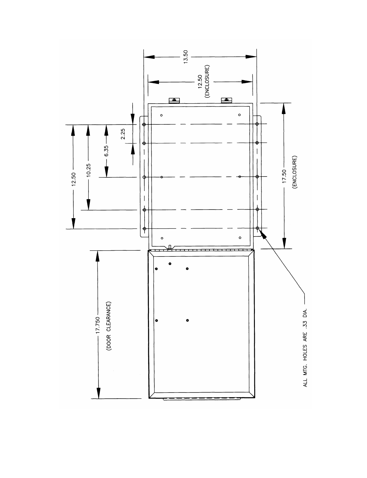
4-2. Receiver Unit Mounting Location
Considerations (See Figure 4-2).
The receiver unit requires a mounting area of approximately
14" wide by 18" long. A depth of at least 18" must be pro-
vided to allow the cabinet door to open.
Ensure the mounting location is as far as possible from
exposed trolley wires and sources of electromagnetic or
radiated noise.
If possible, avoid installing receiver unit to a surface where
high vibration or shock is present. If this can not be avoided,
use appropriate shock mounts.
4-3. Line Input Considerations.
WARNING
THE UNIT MUST BE WIRED TO THE CORRECT
VOLTAGE, FAILURE TO DO SO MAY DAMAGE THE
SYSTEM.
The receiver unit has direct and separate connect provisions
for operation from 120 or 240 VAC (nominal), 50-60 Hz
power.
For applications where line voltage deviation exceeds 20%
of nominal values or if 440 VAC power is used, a step up or
step down transformer must be used.
NOTE
The receiver unit should not be connected to lines contain-
ing excessive power up transients or continuous commuta-
tor noise. A line conditioner may be necessary in some
installations.
4-4. EZ Setup
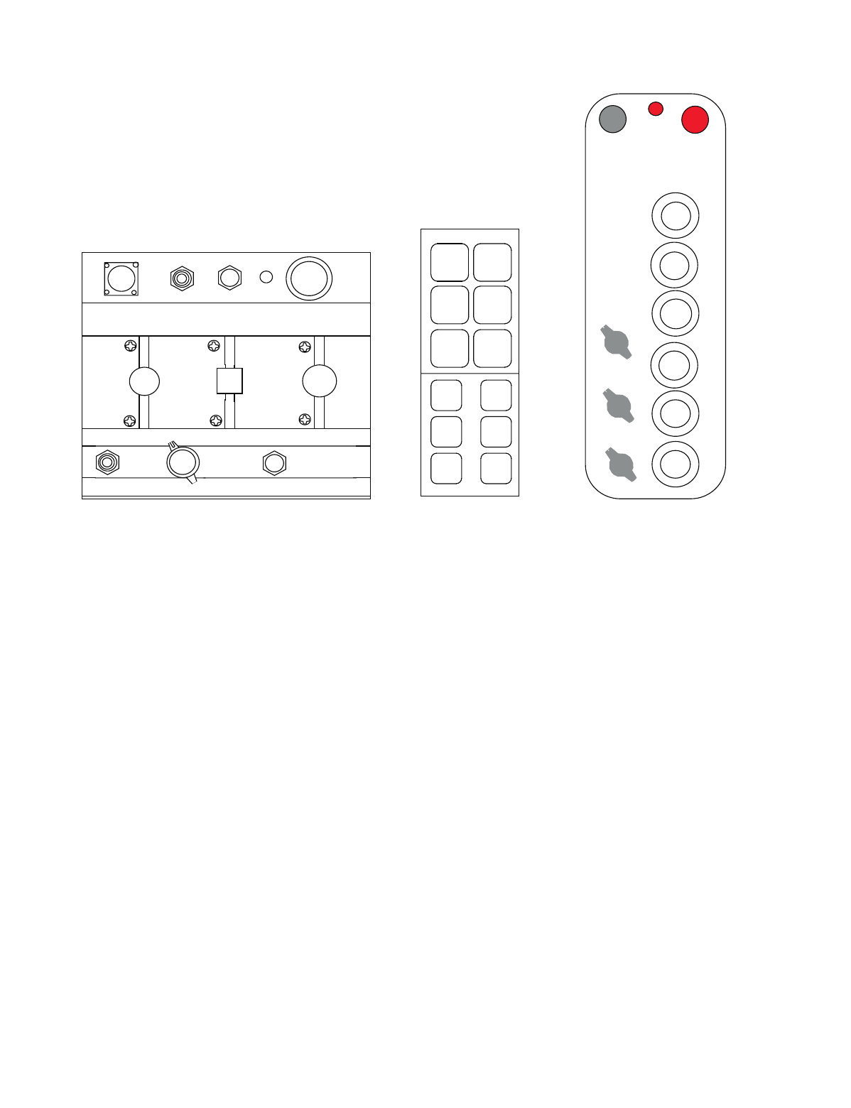
1. Determine the type of transmitter you have with your
unit. SLTX, membrane or pendant as shown in Figure
4-1. (For custom or special transmitter refer to custom
documentation).
2. Refer to Appendix A, Appendix B, or Appendix C and
select the wiring configuration that matches your
application.
3. Refer to the transmitter switch programming table at
the bottom of the page for the selected configuration.
4. If necessary, open the transmitter and set the switches
as shown in the configuration diagram. Normally you
unit is pre-programmed at the factory and only installa-
tion is necessary. The programming information for the
transmitter and receiver is only needed for systems
purchased un-programmed or to change system pro-
gramming. Switch locations are in Section 6. DO NOT
CHANGE SWITCH SW1 OR SW2. These switches
program the access code and must be programmed to
match the receiver. After setting these switches reas-
semble the transmitter. Make sure fully charged batter-
ies are placed in the unit.
5. Determine if you need to special program the receiver.
NORMALLY YOU WILL NOT NEED TO CHANGE
RECEIVER SWITCH SETTINGS. Change the
receiver settings only to add latched functions, multi
box or alarm settings. For information on theses set-
tings see page 6-1.
6. Go to paragraph 4-5 Receiver Unit Cabinet Mounting.
4-5. Receiver Unit Cabinet Mounting.
Recommended mounting hardware is four - 1/4-20 hex
machine screws of appropriate length, four 1/4-20 x 7/16
"keps" or elastic stop nuts.
Flat washers should be used in front of nuts when receiver
unit is mounted to a non structural surface.
Mount receiver unit cabinet securely to mounting surface.
4-6. Receiver Installation (See Figure 4-2).
1. Mounting area, approximately 14" wide by 18" long.
2. Ensure mounting location is as far as possible from
exposed Trolley wire and sources of electromagnetic
or radiated noise. Antenna should be pointed straight
up.
3. Mount unit and install antenna.
4. Set switch SW1 on power supply to off position
towards right of cabinet. Set switch SW1 on computer
module to the left to disable radio outputs.
Section 4 - Installation Information
Section 4 - Installation Information (Continued)
4-2
SLTX MEMBRANE PENDANT
Figure 4-1. Tranmitter Type
5. Connect power leads to right lower terminal strip J1 on
power supply board to either 120 and ground or 240
and ground. See page 6-1.
6. Use Appendix A, Appendix B or Appendix C and pick
a diagram that fits the interface. All control wiring for
the interface should be connected at terminals to J2 on
relay output board. Note: J3 terminal block is prewired
for single common control transformer. When using
more than one control transformer the jumpers on J3
must be removed and J3 should be wired for the proper
voltage per terminal.
7. In the lower right side of the receiver cabinet on the
power supply board you will find relay K1 (MR). Ter-
minals 2 and 4 are used to control any master relay
function of the control. Relay K1 is shown in the wir-
ing diagrams in Appendix A, Appendix B and Appen-
dix C.
8. Wiring of the 10K system should now be complete.
9. Apply power.
10. Check out radio functions with the outputs disabled.
Light DS3 should be out at this time. After the check,
put S1 back to the on position DS3 should light. Check
function and direction by jogging each motion. Instal-
lation should now be complete.
4-7. Special Receiver Functions.
4-7.1. Master Control Relay (MCR) Enable
(S1)
This switch, when turned to off, disables the MCR and
removes all output power to all output relays. This allows
testing of the receiver control circuitry without activating
any external functions such as motors and horns.
4-7.2. Auxiliary Functions General
The 10K receivers have auxiliary (Aux) function capability.
These Aux functions are dedicated relays that can be used to
sound horns, light lights or other functions. Typically a
10K12 has 3 Aux functions and a 10K16/24 has 4. How-
ever, there are a number of specialties and variations avail-
able. If your transmitter does not have a document
describing these functions, the easiest way to determine
what the Aux functions do is to look at the relay control
boards and while depressing the appropriate Aux switch on
the transmitter see which LED lights for which relay.
WARNING
MAKE SURE S1 MASTER CONTROL RELAY (MCR) IS
TURNED OFF BEFORE ATTEMPTING THIS TO PRE-
VENT ACTIVATION OF EXTERNAL CIRCUITRY. SEE
PAGE 6-1.
AU X 1
AU X 2
AC CE SS C OD E AU X 3
AU X 4
SO UT H WEST DO W N
ON
OF F
BATT ER Y
M ON ITOR
ON -OFF
KEY
EA ST UP
NOR TH
BR IDGE TR OL LEY HO IST
H1 H2
SE LECT EM S
B
OFF -ON
OFF -ON
OFF -ON
H2/T2
H1/T1
H3/T3
ON /OFF EM S
HO IST
DIR1
HO IST
DIR2
TRO LLEY
TRO LLEY
DIR1
DIR2
BRIDG E
DIR1
BRIDG E
DIR2
UP DN
E W
N S
1 2
3
E
STOP
ON OFF
Section 4 - Installation Information (Continued)
4-3
Figure 4-2. Receiver Mounting

Section 4 - Installation Information (Continued)
4-4
4-7.3. System Functions Selection
Special programming exists to allow some of the Aux relays
to be dedicated for special system functions. Setting certain
dip switches on the CPU Board enables this programming.
4-7.4. Auto Alarm and EMS Alarm
You can have either one of these functions or both. The use
of either one of these two functions dedicates one specific
control relay to operate an external alarm. An external
alarm (not supplied) needs to be connected to this relay.
4-7.4.1. Auto Alarm (S2-1)
4-7.4.1.1. Description
Gives about 5 seconds of alarm when the transmitter is first
turned on.
4-7.4.1.2. To Enable
Connect an external alarm. Move dip switch S2-1on the
CPU Board to the ON position. See page 6-1 for switch
details and for location of the Alarm Relay. See the appro-
priate wiring diagram in Appendix A, Appendix B or
Appendix C.
4-7.4.2. Emergency Stop (EMS) Alarm (S2-2)
4-7.4.2.1. Description
Gives about 5 seconds of alarm when the Emergency Stop
(EMS) is activated on the transmitter.
4-7.4.2.2. To Enable
Connect an external alarm. Move dip switch S2-2 on the
CPU Board to the ON position and set jumper JU2 to the
upper position. (As a safety measure during EMS shutdown
all control lines to relays are disabled. Jumper JU2 facili-
tates bypassing the EMS shutdown to the Alarm Relay so it
can be activated during an EMS shutdown.) See page
6-1 for switch and jumper details and for location of the
Alarm Relay. See the appropriate wiring digram in Appen-
dix A, Appendix B or Appendix C.
4-7.5. Master Control Relay (MCR)
Monitoring Disable (S2-3)
Disables the contact monitoring of the MCR. Used for spe-
cial diagnostic purposes only. In normal operation switch
S2-3 should be set to OFF. Set to ON to disable contact
monitoring of MCR.
4-7.6. Auxiliary Function Relay Latching
(S2-6, -7 and -8)
Enables the appropriate auxiliary function relay to operate
in a latched mode, on or off, rather than as a momentary
contact. Which function is latchable and which relay is
latched depends on the particular transmitter used.
Switch S2, positions 6 through 8 on the CPU Board each
enable a separate relay to be latched when turned on. If your
transmitter does not have a document describing these func-
tions, the easiest way to determine correlation of transmitter
function, relay position and dip switch position, is to try
various dip switch setting and see which relays are latched
and which transmitter controls them. Make sure all three
switch positions are off, turn S2-6, S2-7 and S2-8 on sepa-
rately and note which relay is affected by the appropriate
LED indication.
WARNING
MAKE SURE S1 MASTER CONTROL RELAY (MCR) IS
TURNED OFF BEFORE ATTEMPTING THIS TO PRE-
VENT ACTIVATION OF EXTERNAL CIRCUITRY.
4-7.7. Time Out Timer Enable (S3-2)
The receiver contains a time out timer. If a receiver once
turned on by a transmitter does not receive a signal from a
transmitter for a period of 15 minutes the receiver shuts
down. Setting S3-2 to ON disables this function.
4-7.8. Multibox Enable (S3-3)
One transmitter can only control the 10K receiver with a
specific access code at a time. However, Multibox capabil-
ity allows the 10K receiver to automatically switch to a new
transmitter when the current controlling transmitter has
been turned off and a new transmitter turned on. Up to 4
different transmitters can control one receiver. To enable
this function the receiver must be preprogrammed from the
factory for Multibox; the appropriate Multibox dip switch
enabled (S3-3) and the correct access codes must be pro-
grammed into the appropriate transmitters. (Note: access
codes are factory programmed into the receiver and the
access codes are sequential.). Switch S3-3, when turned on,
enables Multibox. Turning off S3-3 in 10K receiver pre-
programmed from the factory for Multibox disables this
function. S3-3 has no function in a receiver that is not pre-
programmed by the factory for Multibox. For specific pro-
gramming information see page 6-1.

5-1
5-1. Diagnostic Led's.
Series 10K12/24M (see page 6-1)5-1.1. Microprocessor Control Module
The function of each LED is described in Table 5-1.
Table 5-1. Diagnostic LED Function
LED COLOR FUNCTION
DS1 Green Monitors the 12 VDC power to the Microprocessor Control Board.
Normally ON.
If 12 VDC power is present then LED is illuminated. LED is off if 12 VDC power is not present.
Check power supply, fuses and if power is on to receiver.
DS2 Green Monitors + 5 VDC regulated voltage.
Normally ON.
If 5 VDC power is present then LED is illuminated. LED is off if 5 VDC power is not present.
Check connectors, the +5 VDC regulator, or for shorts on the board.
DS3 Red Monitors closure of the Master Control Relay (MCR) relay (K1).
LED will be illuminated when the MCR relay has been enabled by an ON command recieved from
the Transmitter Unit. Led will extinguish, when an OFF command has been transmitted, an EMS
condition is present, or SW1 is set to 0.
The MCR controls the 12 VDC power to the Master Relay on the Power Supply Board.
DS4 Yellow Monitors closure of the Security Relay output (K2).
The LED will be illuminated when the Security Relay has been enabled by an ON command
received from the Transmitter Unit. LED will extinguish when an OFF command is transmitted, or
an EMS condition is present.
The Security Relay controls the 12 VDC power to the MCR relay (K2) and the power to the coils
of the control relays (K1 through K8) on the Relay Output Modules.
DS5 Yellow Monitors the AC bias pump line for the Security Relay (K2).
LED will flash only when the Receiver has been enabled by an ON command.
The Security Relay is enabled by an AC signal generated by the slave microcomputer. The AC
signal is capacitively isolated from the slave microcomputer to help prevent the Security Relay
from being latched ON if the slave microcomputer fails. LED will not be illuminated when an OFF
command has been sent or an EMS condition is present.
DS6 Yellow Monitors AC bias pump line for the Master Control Relay (K1).
LED will flash only when the Receiver Interface Control Module has been enabled by an ON
command.
The Master Control Relay (K1) is enabled by an AC signal generated by the slave microcomputer.
The AC signal is capacitively isolated from the slave microcomputer to help prevent the MCR from
being latched ON if the slave microcomputer fails. The LED will not be illuminated when an OFF
command has been sent or is in an EMS mode.
DS7 Yellow Monitors data synchronization. (Flashes when a properly formatted data signal is received from
the transmitter).
This LED will flash rapidly when data is transmitted. The LED can be used with DS9 to analyze
incoming data. If DS9 is illuminated or flashing when DS7 also is flashing, another Transmitter
Unit on the same frequency may be present. This is normal. As more Transmitter Units operated
on the same frequency, LED will flash brighter and more often.
Section 5 - Troubleshooting

Section 5 - Troubleshooting (Continued)
5-2
Table 5-1. Diagnostic LED Function (Continued)
LED COLOR FUNCTION
DS8 Yellow Monitors continuity between receiver and CPU modules.
Normally ON.
Off indicates a malfunctioning receiver.
DS9 Red Monitors received data errors.
Normally OFF.
A flashing LED during data transmission may indicate interference of the received data. If LED is
illuminated continuously when data is transmitted and the system will not respond the Access Code
of the Receiver and Transmitter Units may not match. If LED is illuminated when data is not
transmitted, another Transmitter Unit may be present on the same frequency with a different
Access Code. The presence of activity on this LED does not necessarily indicate a problem. It
should be used with other indicators in analyzing system status.
DS10 Yellow Monitors system acitivty.
Normally FLASHING.
If not flashing the microprocessor is dead.
DS11 Red Monitors the ON command from the Transmitter.
LED will flash when an ON command is being received from the Transmitter.
While pushing the ON button on the Transmitter this should light.
DS12 Red Monitors the OFF command from the Transmitter.
LED will flash when an OFF command is being received from the Transmitter Unit.
While pushing the OFF button on the Transmitter this should light.
DS13 Red Monitors EMS condition.
Normally OFF.
LED will flash when an EMS command is transmitted and illuminate continuously when the EMS
condition is in effect. An EMS condition may be created when an EMS command is transmitted or
when a failure mode is detected by the slave microcomputer. If both DS11 and DS13 are
illuminated, a contact monitoring error has been detected. If both DS9 and DS13 are illuminated,
the incoming data on the ICC bus has been corrupted.
DS14 Yellow Monitors the AC activity for the Security Relay (K1).
Normally ON.
If the system is ON and the light is not lit there is a serious microprocessor error.
DS15 Red Monitors the watchdog timer.
Normally OFF.
The LED will illuminate momentarily when power is applied to or removed from the system. If the
LED is continuously flashing or on, the computer is not working properly. If LED is illuminated
constantly (no flashing), the +5 VDC is probably too low. This could be caused by shorts on the
board or by a defective voltage regulator. If the LED flashes at a constant rate, the microcomputer
chip or EPROM may be defective.
DS16 Not used.

Section 5 - Troubleshooting (Continued)
5-3
5-1.2. Power Supply Module
The function of each LED is described in Table 5-2.
Table 5-2. Diagnostic LED Function
5-1.3. Relay and Output Modules
The function of each LED is described in Table 5-3.
Table 5-3. Diagnostic LED Function
5-2. Output Module Testing.
The output module may be tested with a transmitter without
activating crane controls by setting SW 1 to off. This allows
the system to be tested and analyzed without causing move-
ment of the crane by removing power to the master relay.
LED COLOR FUNCTION
DS1 Green Monitors unregulated 12 VDC.
Normally ON.
Check fuse, wiring to unit and AC power to unit.
DS2 Green Monitors regulated 12 VDC.
Normally ON.
DS2 off and DS1 on, check for shorts on regulated output or blown regulator. Disconnect power
supply connector to computer control board, if DS2 light comes back on there is a short on one of
the other boards.
LED COLOR FUNCTION
DS1-6
or
DS1-8
Red Monitors the power to the relay coil or switching device.
Normally OFF unless command is sent to turn ON.
The numbers of LEDs depend on the number of functions per board. LEDs are located next to the
relay or switch they control. Ground is switched to the relay coil or switch to turn it on; this also
turns on the light.
DS7
or
DS9
Yellow Monitors 12 VDC to the relay or output module.
Normally ON.
LED off indicates no power to the relay or output module.

Section 5 - Troubleshooting (Continued)
5-4
This Page Intentionally Left Blank
6-1
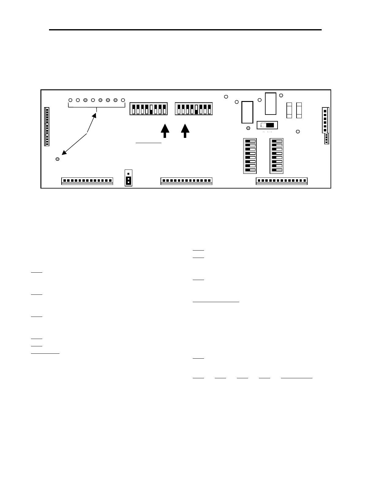
6-1. 10KM Receiver CPU Board Programming
and Servicing Information
The receiver CPU board is shown in . Refer to paragraphs
6-1.1 through 6-1.5 for switch and jumper settings.
.
Figure 6-1 Receiver CPU Board Switch and Jumper Locations
6-1.1. S1 Switch Settings
Controls power to the Master Relay. With the switch set to
ON power is on to all relays. Move the switch to OFF for
circuit testing without activating external controls.
6-1.2. S2 Switch Settings
S2-1 Auto Alarm
OFF Auto Alarm Disabled
ON Auto Alarm Enabled
S2-2 EMS Alarm
OFF EMS Alarm Disabled
ON EMS Alarm Enabled
S2-3 Master Control Relay
OFF MCR Disabled
ON MCR Enabled
S2-4 Not used
S2-5 Not used
S2-6, 7 & 8 Aux Relay Latching*
OFF Latching Disabled
ON Latching Enabled
* See the specific configuration for your application for
details on which switch controls which relay.
6-1.3. JU2 Jumper Settings
In the lower position (the position shown) the alarm relay is
disabled after an E-Stop shutdown. This is the factory
default setting. Moving it to the upper position enables it.
See the appropriate Programming Diagram for the Alarm
Relay Location.
6-1.4. S3 Switch Settings
S3-1 Not used
S3-2 Time Out Timer
OFF Time Out Enabled
ON Time Out Disabled
S3-3 Multibox
OFF Multibox Disabled
ON Multibox Enabled
S3-4 10K24 Only*
OFF Aux Trolley
ON Aux Hoist
* Only on the 10K24 with Multibox Enabled. First 4 relays
on J6 are Multibox. Last 4 relays on J6 are either Aux Trol-
ley or Aux Hoist.
S3-5 Not used
6-1.5. S3 Multibox Setting (Only with S3-3 On)
S3-6 S3-7 S3-8 TXS Access Code
OFF OFF OFF 1 Base Address
OFF OFF ON 2 Base Address +1
OFF ON OFF 3 Base Address +2
OFFONON4 Base Address +3
For more Base Address’ please contact Telemotive.
Relay Output Module A Relay Output Module B Relay Output Module C
DS-15
DS2
K1
S1
ON
DS5 DS4 DS1
DS3
J7 J8 J6
Receiver
87654321
87654321
0FF 0FF
S3 S2
Access Code
Membrane SW2 SW1
Pendant SW1 SW2
SLTX SW1 SW2
Toggle SW2 SW1
0FF
87654321
S5
87654321
S4 0FF
Access Code Switches
DS-7 -8 -9 -10-11-12-13-14
J3
J4
J5
JU2
J2
J1
Power
Supply
Diagnostic LEDs
K2
DS6
BA
F2 F1
Section 6 - Programming and Servicing Information
Section 6 - Programming and Servicing Information (Continued)
6-2
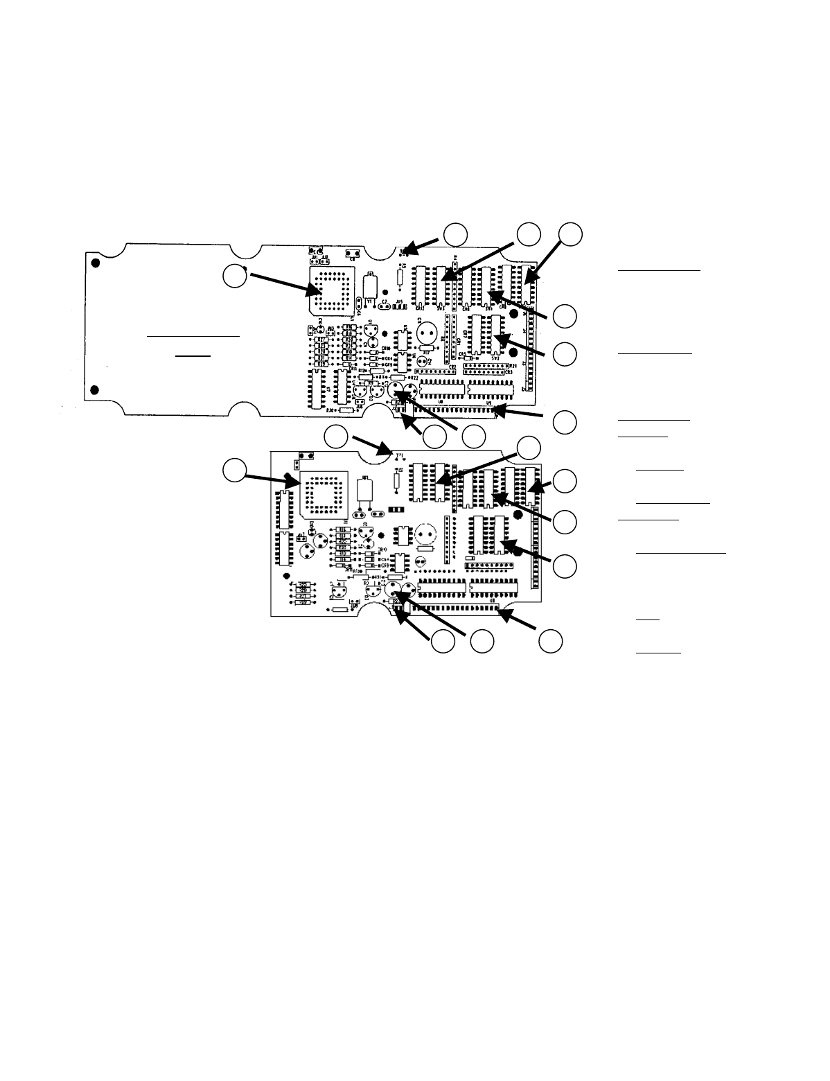
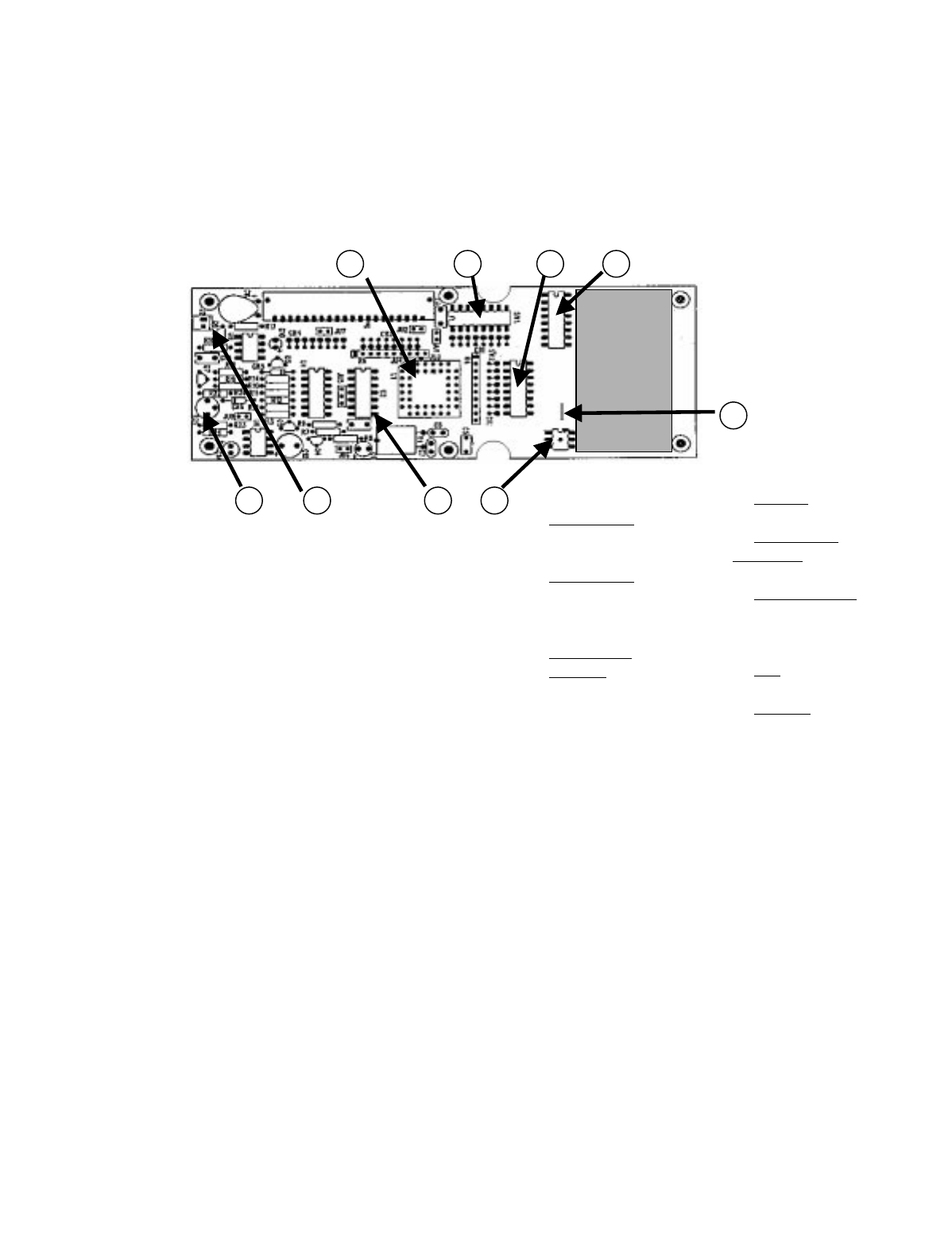
6-2. Pendant Transmitter Board Programming
and Servicing Information
The Pendant Transmitter boards are shown in Figure 6-2.
Refer to paragraphs 6-2.1 through 6-2.3 for servicing proce-
dures.
Figure 6-2. Pendant Transmitter Board
6-2.1. Setting Access Code:
The access code is set at the factory and should not be
changed unless absolutely necessary. If a spare transmitter
unit is used, the receiver unit access code should be
changed to match the access code of the spare transmitter
unit. Access codes are printed on a white label on the out-
side of any transmitter and maybe matched to S4 and S5 on
the receiver microcomputer module without having to open
the transmitter housing.
Switch SW1 (B) in the transmitter must match switch S4
(B) on the receiver microcomputer module and switch SW2
(A) in the transmitter must match switch S5 (A) on the
microcomputer module.
6-2.2. To Check Data
1) For data input use Pin 1 of J1.
2) Use TP1 for External Trigger input.
3) Use Black Lead of Battery for Ground
6-2.3. Battery Monitor Adjustment
Connect power supply to battery leads observing polarity
and set supply voltage to 5.8 volts. Adjust Battery Monitor
pot to just turn off Red LED on the front of the transmitter.
E10681
E10605
Split board Version
1. 2.
3.
4.
7.
6.
5.
1.) Sw3
Auto Time-0ut
Sw3-8 “ON” Disables
Automatic Time-Out
2.) Sw4
Mode Switch
3.) Sw1 “B”
4.) Sw2 “A”
Access Code
Switches
5.) EPROM
6.) Battery cable
connection
7.) Battery Monitor
pot adjustment, set
for 5.8 Volts.
8.) TP1
9.) J1 Pin 1
9.
8.
B
A
7.6. 9.
1.
2.
3.
4.
8.
B
A
5.
Battery Pack
Area
Section 6 - Programming and Servicing Information (Continued)
6-3
6-3. Membrane Transmitter Board
Programming and Servicing Information
The Membrane Transmitter board is shown in Figure 6-3.
Refer to paragraphs 6-3.1 through 6-3.3 for Servicing Pro-
cedures.
Figure 6-3. Membrane Transmitter M/C Module Board
6-3.1. Setting Access Code:
The access code is set at the factory and should not be
changed unless absolutely necessary. If a spare transmitter
unit is used, the receiver unit access code should be
changed to match the access code of the spare transmitter
unit. Access codes are printed on a white label on the out-
side of any transmitter and maybe matched to S4 and S5 on
the receiver microcomputer module without having to open
the transmitter housing.
Switch SW1 (A) in the transmitter must match switch S5
(A) on the receiver microcomputer module and switch SW2
(B) in the transmitter must match switch S4 (B) on the
microcomputer module.
6-3.2. To Check Data
1) For data input use Pin 8 of U3.
2) Use TP1 for External Trigger input.
3) Use Black Lead of Battery for Ground
6-3.3. Battery Monitor Adjustment
Connect power supply to battery leads observing polarity
and set supply voltage to 5.8 volts. Adjust Battery Monitor
pot R21 to just turn off Red LED on the front of the trans-
mitter.
R.F.
Head
J1
M/C MODULE
E10678
1.) Sw3 2Speed
Mode Switch
2.) Sw4 Single Speed
Mode Switch
3.) Sw1 “A”
4.) Sw2 “B”
Access Code
Switches
5.) EPROM
6.) Battery cable
connection
7.) Battery Monitor
pot adjustment, set
for 5.8 Volts. “R21”
8.) TP1
9.) U3 Pin 8
1.
2.
3. 4.
7. 6.
5.
9.
8.
A
B
Section 6 - Programming and Servicing Information (Continued)
6-4
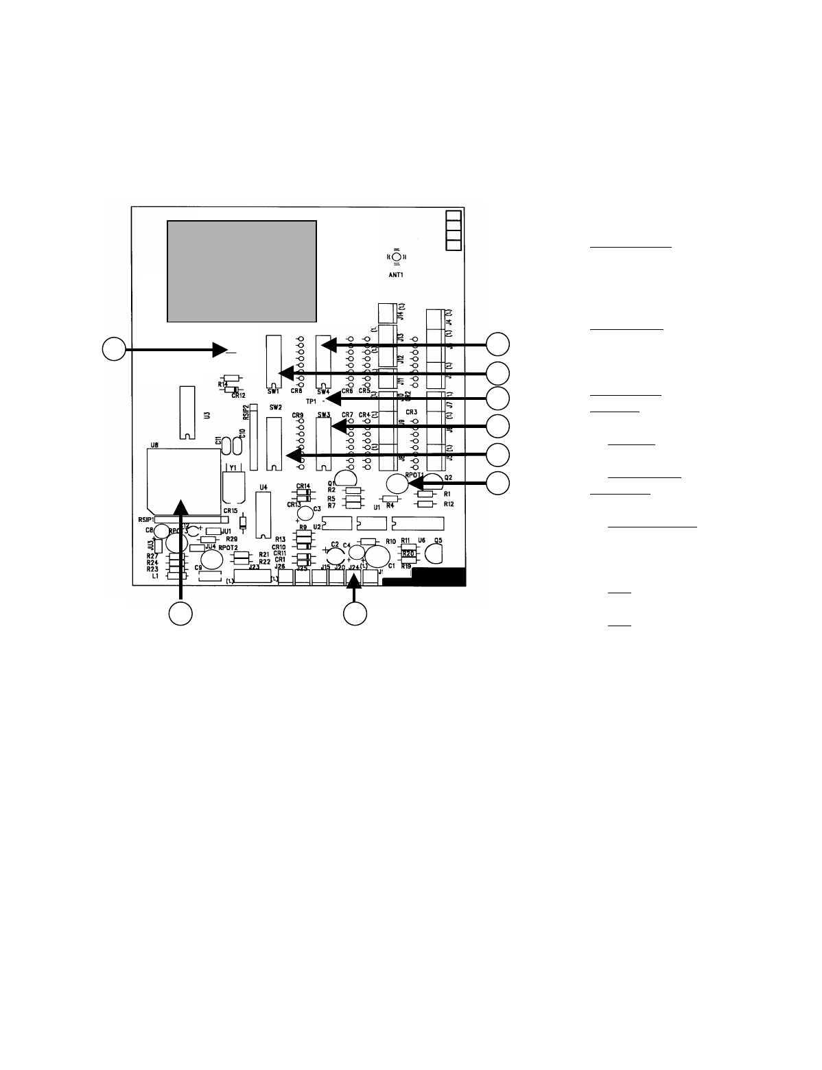
6-4. SLTX Transmitter Board Programming
and Servicing Information
The SLTX Transmitter board is shown in Figure 6-4. Refer
to paragraphs 6-1.1 through 6-4.3 for servicing procedures.
Figure 6-4. SLTX Transmitter Board
6-4.1. Setting Access Code:
The access code is set at the factory and should not be
changed unless absolutely necessary. If a spare transmitter
unit is used, the receiver unit access code should be
changed to match the access code of the spare transmitter
unit. Access codes are printed on a white label on the out-
side of any transmitter and maybe matched to S4 and S5 on
the receiver microcomputer module without having to open
the transmitter housing.
Switch SW1 (B) in the transmitter must match switch S4
(B) on the receiver microcomputer module and switch SW2
(A) in the transmitter must match switch S5 (A) on the
microcomputer module.
6-4.2. To Check Data
1) For data input use TP3.
2) Use TP1 for External Trigger input.
3) Use Black Lead of Battery for Ground
6-4.3. Battery Monitor Adjustment
Connect power supply to battery leads observing polarity
and set supply voltage to 5.8 volts. Adjust Battery Monitor
pot RPOT1 to just turn off Red LED on the front of the
transmitter.
B
A
1.) Sw3
Auto Time-0ut
Sw3-8 “ON” Disables
Automatic Time-Out
2.) Sw4
Mode Switch
3.) Sw1 “B”
4.) Sw2 “A”
Access Code
Switches
5.) EPROM
6.) Battery cable
connection
7.) Battery Monitor
pot adjustment, set
for 5.8 Volts. RPOT1
8.) TP1
9.) TP3
2.
3.
4.
7.
1.
8.
J24 - +
6.5.
TP3
R.F. Head
M/C MODULE
E10602
9.
Section 6 - Programming and Servicing Information (Continued)
6-5
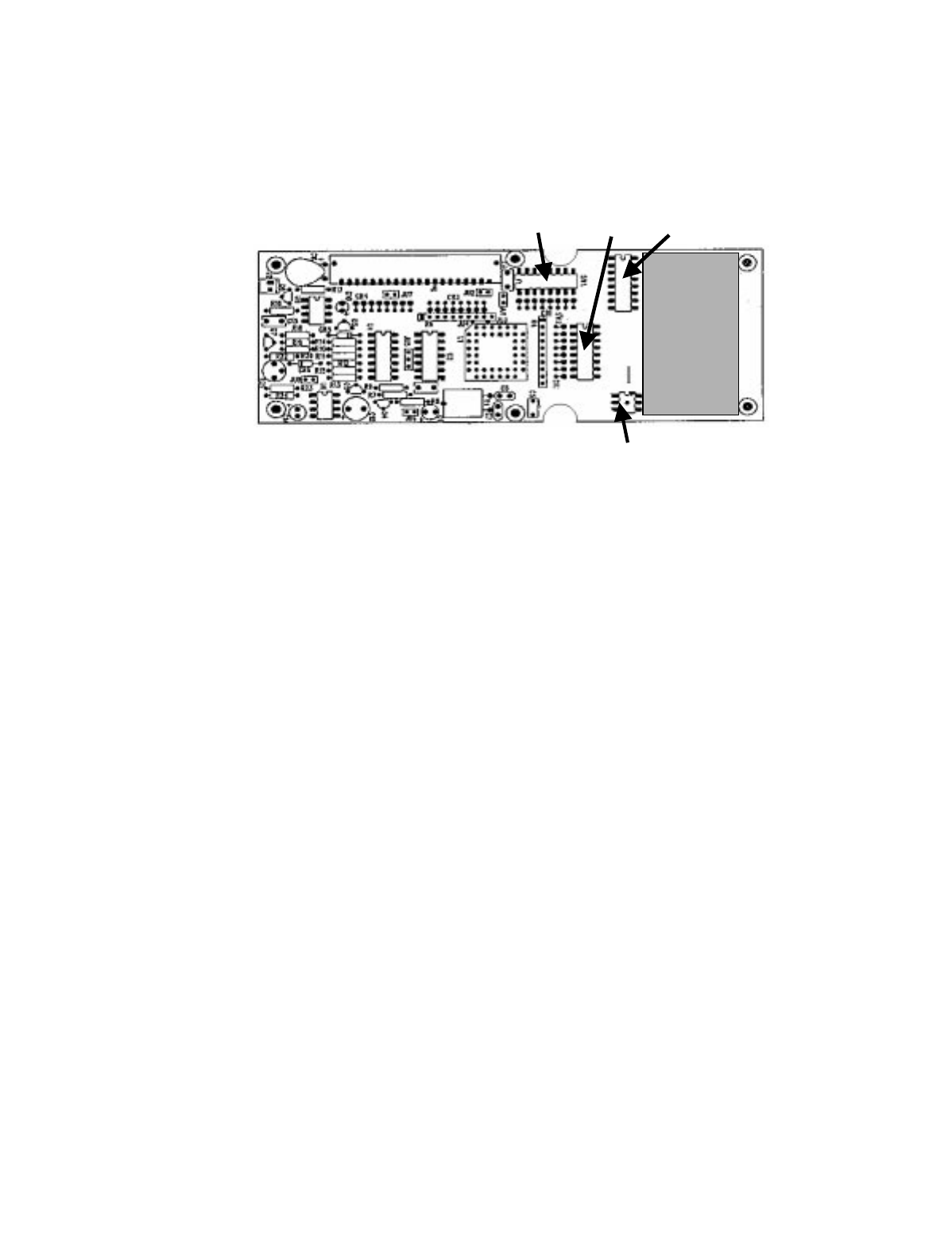
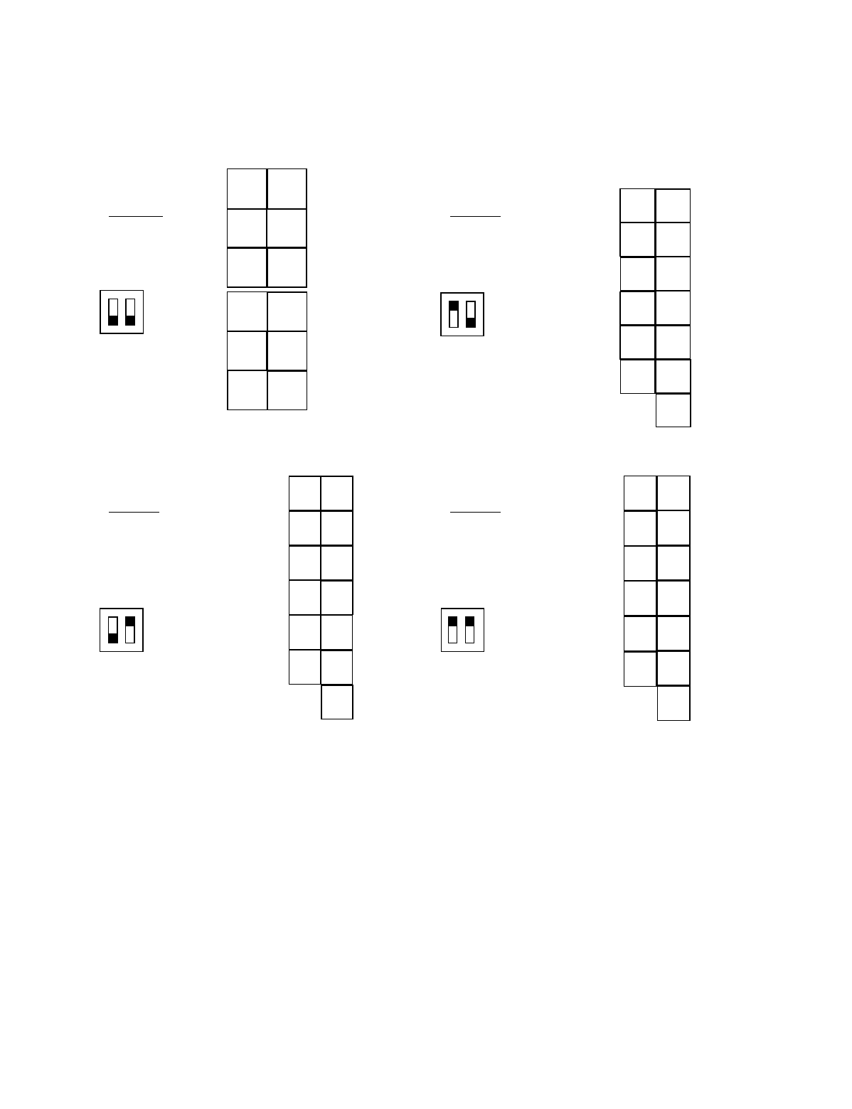
6-5. Membrane Transmitter Mode Select
The Membrane Transmitter M/C module board is shown in
Figure 6-5. Figure 6-6 provides switch settings for each
operating mode.
Figure 6-5. Membrane Transmitter M/C Module Board
NOTE: This section listed for reference only. This section details how to program the E10678 Membrane Transmitter
Board for use in single speed transmitters. For all single speed modes (1 through 3) Sw3 must set to all “OFF”.
R.F.
Head
J1
Sw1 (A)
Sw4 for single speed only
Sw2 (B) Sw3 for 2 speed only
M/C MODULE
E10678
Section 6 - Programming and Servicing Information (Continued)
6-6
Figure 6-6. M/C Module Mode Switch Settings
Mode 3:
Allows for 12
independent
on/off functions
Sw4 settings.
1 2 ON
OFF
RECEIVER
OUTPUTS RECEIVER
OUTPUTS
67
5 8
49
310
211
12
E
STOP
1
AJ2-6
AJ2-5
AJ2-4
AJ2-3
AJ2-1
AJ2-2
BJ2-1
BJ2-2
BJ2-3
BJ2-4
BJ2-5
BJ2-6
NOTE: This section listed for reference only. This section details how to program the E10678
Membrane Transmitter Board for use in single speed transmitters. For all single speed modes
(1 through 3) Sw3 must set to all “OFF”.
Mode 2:
Four motor single speed
with four auxiliaries
Sw4 settings.
1 2 ON
OFF
AUX
UP UP
AUX
DN DN
P1 E
P2 W
ALARM S
N
E
STOP
LIGHT
AJ2-6
AJ2-5
AJ2-4
AJ2-3
AJ2-1
AJ2-2
BJ2-1
BJ2-2
BJ2-3
BJ2-4
BJ2-5
BJ2-6
RECEIVER
OUTPUTS RECEIVER
OUTPUTS
Mode 1:
Four motor single speed
with four auxiliaries
Sw4 settings.
ON
OFF
1 2
EUP
WDN
NAUX
UP
SAUX
DN
E
STOP
AJ2-6
AJ2-5
AJ2-4
AJ2-3
AJ2-1
AJ2-2
BJ2-1
BJ2-2
BJ2-3
BJ2-4
BJ2-5
BJ2-6
RECEIVER
OUTPUTS RECEIVER
OUTPUTS
2
1
3
4
Mode 0:
For all 2 speed
applications
Sw4 settings
1 2 ON
OFF
UP DN
EW
NS
12
3E
STOP
ON OFF

7-1
7-1. 10K Receiver Spare Parts
PART
NUMBER DESCRIPTION
E13151-5X UHF RECEIVER MODULE
E10163-1 CPU EPROM (10K12 SINGLE BOX) System ROM FW2832-0
E10163-2 CPU EPROM (10K12 MULTI-BOX) System ROM FW2833-0
E10163-3 CPU EPROM (10K16/24 SINGLE BOX) System ROM FW2834-0
E10163-4 CPU EPROM (10K16/24 MULTI-BOX) System ROM FW2835-0
E10171-0 POWER SUPPLY MODULE
E10165-0 OUTPUT RELAY MODULE (6 RELAYS)
E10112-0 OUTPUT RELAY MODULE (8 RELAYS)
K2116-1 RELAY DPST-N.O. 25A, 12VDC COIL (POWER SUPPLY BOARD)
K1304-0 RELAY SPDT, 16A, 12VDC COIL (OUTPUT BOARD)
F2711-0 FUSE, 10A, 250V, 5X20mm SLO-BLO
F2711-1 FUSE, 1.0A, 250V, 5X20mm SLO-BLO
F2711-3 FUSE, 0.3A, 250V, 5X20mm SLO-BLO
W1098-2 JUMPER, INSULATED, 2-CIRCUITS
W1098-4 JUMPER, INSULATED, 4-CIRCUITS
AN100-0 ANTENNA
E2028-2 OPTIONAL REMOTE EXTERNAL ANTENNA KIT
JUMPER WIRE 3 CIRCUITS
Section 7 - Spare Parts

Section 7 - Spare Parts (Continued)
7-2
7-2. 10K Pendant Transmitter Parts
BLACK = 0 YELLOW = 1
PART
NUMBER DESCRIPTION
E10668-X (NOTE 1) CASE, TOP PENDANT, COMPLETE WITH SWITCHES, DECALS, BOOTS, ETC.
A10668-X (NOTE 1) CASE, TOP PENDANT, WITH EYELETS
MP10668-X (NOTE 1) CASE ONLY, TOP PENDANT
A1011 (NOTE 2) BOOTS
H634-0 BOOT, GRAY
H635-0 BOOT, RED
H2055-3 LENS/MOUNT, LED W/SPACER, RED
S1039-2 SWITCH, PUSH BUTTON, 2-SPEED SBRU-SD
S1039-HK SWITCH, PUSH BUTTON, 3-SPEED SBRU-TD
S1026-0 SWITCH, PUSH BUTTON, MOM N/0
S1040-0 SWITCH, ROTARY, SP3T
S1041-0 SWITCH, TOGGLE, SPDT, CTR OFF
MP10666-0 KNOB, ROTARY 1/2" DIA., BLACK
MP10675-0 BOOT, TOGGLE SW., BLACK
A10667-3 REPLACEMENT BOTTOM CASE W/GASKET AND BATTERY DOOR, YELLOW
A10667-2 REPLACEMENT BOTTOM CASE W/GASKET AND BATTERY DOOR, BLACK
MP10667-X CASE ONLY, BOTTOM
A10667-X BOTTOM CASE W/O BATTERY DOOR
A10669-X BATTERY DOOR W/FOAM, W/O SCREWS AND LATCH
MP10676-0 FOAM, BATTERY DOOR
MP10677-0 GASKET FOR BOTTOM CASE
MP10650-X LATCH FOR BATTERY DOOR
H251-0 SCREW FOR BATTERY DOOR LATCH
H252-0 WAVE WASHER FOR BATTERY DOOR LATCH
H2034-0 FLAT WASHER FOR BATTERY DOOR LATCH
H1047-0 COVER SCREWS
N10663-0 ACCESS CODE LABEL
N10666-0 FCC LABEL
A10670-0 BATTERY HOLDER ASSEMBLY, W/CABLE
H1049-0 SCREW, BATTERY BRACKET
MP10680-0 O'RING
MP10678-0 SHOULDER STRAP
BT10KP-0 BATTERY, ALKALINE
BT10KP-1 BATTERY, NICAD
E1670-1 BATTERY CHARGER
NOTE 1 BLACK = 0 YELLOW = 1
NOTE 2 UP DOWN EAST WEST NORTH SOUTH
BLACK341112 910
YELLOW232431322930

Section 7 - Spare Parts (Continued)
7-3
7-3. Membrane Transmitter Unit Spare Parts
PART
NUMBER DESCRIPTION
A9654-0 STRAP ASSEMBLY
E9654-0 BATTERY HOLDER ASSEMBLY
A10662-1 TRANSMITTER CASE ASSEMBLY
A10663-1 BEZEL ASSEMBLY (SINGLE-SPEED TRANSMITTER)
A10663-2 BEZEL ASSEMBLY (TWO-SPEED TRANSMITTER)
A10664-1 BATTERY DOOR ASSEMBLY
S313-1 MEMBRANE SWITCH (SINGLE-SPEED TRANSMITTER)
S314-1 MEMBRANE SWITCH (TWO-SPEED TRANSMITTER)
S2803-0 MEMBRANE SWITCH (TACKILE)
MP9653-1 GREY PLASTIC KEY
A9657-1 INSERT PACKAGE (SINGLE -SPEED TRANSMITTER)
A9659-1 INSERT PACKAGE (TWO-SPEED TRANSMITTER)
MP9656-0 VINYL POUCH
A9665-0 RUBBER BOOT ASSEMBLY

Section 7 - Spare Parts (Continued)
7-4
7-4. Small Lever Transmitter Unit Spare Parts
PART
NUMBER DESCRIPTION
A231-204 ASSEMBLY, KEY SWITCH & CABLE, TX
A232-X ASSEMBLY TOGGLE SWITCH & CABLE, TX
A234-2 ASSEMBLY, LED W/CONNECTOR
A235-0 ASSEMBLY, ROTARY SWITCH & CABLE, TX
A10685-1 ASSEMBLY BATTERY CONTACT BOARD
A2260-0 ENDCAP ASSEMBLY, BATTERY SIDE
A2261-X ENDCAP ASSEMBLY, ANTENNA SIDE
E10601-X 10KSL:TX CPU MODULE
H633-0 BOOT, TOGGLE, RED
H634-0 BOOT, PUSHBUTTON, GREY
H635-0 BOOT, PUSHBUTTON, RED
H638-0 BOOT, TOGGLE, GREY
H2055-3 LENS, LED
MP135-1 KNOB/KEY ASSEMBLY, MOLDED
MP630-0 KNOB, CYLINDER 5/8 DIAMETER
MP632-0 KNOB, SQUARE 4/8 SQUARE
MP681`-0 KNOB, SPHERICAL 3/4 DIAMETER
MP2161-X TOP PANEL EXTRUSION 10KSLTX
N10170-X LABEL TX FUNCTIONS, WRITE-IN
N10171-X LABEL TX FUNCTIONS
S763-101 MOTION SWITCH 5-SPEED STEPPED
WA4645-0 RECEPTACLE, CODE PLUG
WA4647-X CODE PLUG ENGRAVED WITH ACCESS CODE

8-1
CAUTION
BEFORE OPERATING THE TRANSMITTER FAMIL-
IARIZE YOURSELF WITH ALL SAFETY INFORMA-
TION IN THIS MANUAL AND ANY OTHER LOCAL,
STATE, OR FEDERAL RULES OR REGULATIONS
ALREADY IN EXISTENCE.
8-1. Power On/Off Push-Button
Pressing the ON/OFF push-button switch turns on the trans-
mitter. Pushing it again will turn the unit off.
8-2. E-Stop
When depressed all equipment movement is immediately
stopped. The transmitter must be turned off and on again to
restore normal operation.
8-3. Motion Push Buttons, Joysticks Or Levers
To active motor functions, press and hold the push-button
that corresponds to the desired motion. To activate higher
speed functions for those models so equipped press the
motion switch a little farther.
8-4. Transmitter LED Indicator
The transmitter LED indicates on, transmitting and low bat-
tery voltage. A slow flash rate indicates the unit is on. A
rapid flash rate indicates a unit is transmitting (when a but-
ton is depressed). If the battery goes below a safe level the
LED will not light, replace battery immediately.
8-5. Time-Out-Timer
Unless disabled the transmitter will turn itself off if not used
for 15 minutes.
8-6. Key Switch (For Models So Equipped)
For models so equipped, turning the key switch on enables
power to the unit. The ON/OFF push button must still be
pushed to turn the unit on. Under normal procedures it is
recommended that the unit be turned off with the ON/OFF
push button before turning of the key switch.
8-7. Servicing Information
CAUTION
FOR PRODUCT MODELS LISTED IN COMPLIANCE
WITH UL, CSA AND ANSI INTRINSICALLY SAFE
STANDARDS, DO NOT ATTEMPT TO REPAIR WITH-
OUT USING TELEMOTIVE APPROVED REPLACE-
MENT PARTS. FAILURE TO DO SO COULD VOID
LISTING AND CREATE A SAFETY HAZARD. FOR
INTRINSICALLY SAFE PRODUCTS ONLY QUALI-
FIED TRAINED SERVICE PERSONNEL ARE
ALLOWED TO PERFORM REPAIRS. FAILURE TO
USE APPROVED SERVICING TECHNIQUES AS WELL
AS TELEMOTIVE APPROVED PARTS FOR INTRINSI-
CALLY SAFE PRODUCTS COULD CREATE A
SAFETY HAZARD. IF THERE IS ANY QUESTION AS
TO WHOM IS QUALIFIED, WHAT PARTS TO USE OR
PROPER SERVICE PROCEDURES PLEASE CONTACT
YOUR TELEMOTIVE REPRESENTATIVE.
Section 8 - Transmitter Operation

Section 8 - Transmitter Operation (Continued)
8-2
This Page Intentionally Left Blank

A-1
NOTE: This section also contains information on Optional Output Board for Multibox and other
optional outputs for the 10K18.
Appendix A - 10K12/18 Pendant and SLTX
Transmitter Programming

Appendix A - 10K12/18 Pendant and SLTX
Transmitter Programming (Continued)
A-2
A-1. Transmitter Switches Sw3 and Sw4
Programming. (See Sections 6-2 and 6-4 for
physical location of transmitter switches).
A-1.1. Transmitter programming Sw3
A-1.1.1. Positions 1-3 (Pendant only) Switch
Positioning. (Standard configuration all
“OFF”).
The functional positions of the various buttons controlling
the hoist trolley and bridge can be moved by transmitter dip
switch Sw3 also. Positions Sw3-1 through Sw3-3 control
these functions. No change in receiver wiring is needed to
use these functions. See TABLE 1(m) for switch verses
button configurations.
A-1.1.2. Positions 1-3 (SLTX only) no function.
(Keep turned “OFF”).
A-1.1.3. Positions 4-7 no function. (Keep
turned “OFF”).
A-1.1.4. Position 8 Time-out-timer Disable.
(Normally keep turned “OFF”).
The transmitter has an approximate 15-minute time-out-
timer. If the transmitter is not used for over 15 minutes it
will shut down. This transmitter time-out-timer function is
transmitter dip switch selectable. Sw3 position 8 disables
the time-out-timer. Turning Sw3-8 “ON” disables the time-
out-timer.
A-1.2. Transmitter programming Sw4
A-1.2.1. Position 1-2 Mode Enable. (Standard
Mode 1 keep 1-2 turned “OFF”).
Mode 1, Sw4 1-2 all “OFF”. The 10K12 single speed sys-
tem comes standard configured this way from the factory
with three motion controls and six auxiliaries (controlled by
the toggle switches). The 10K12 2-speed system comes
standard configured this way from the factory with three 2-
speed controls and three auxiliaries (controlled by the toggle
switches, the rotary is non-functional).
Mode 2, Sw4 1 turned “OFF” and Sw4 2 turned “ON”. The
10K12 2-speed system configured this way is able to control
four 2-speed motion controls and no auxiliaries this give
bridge, trolley, main and aux hoist. The rotary selector
switch functions are H1 main hoist, H2 aux hoist and B both
main and aux hoist (the toggle switches are non-functional).
Mode 3, Sw4 1 and 2 turned “ON”. The 10K12 2-speed
system will control up to 5 motors using the rotary selector
switch. This mode reconfigures two of the 10K12 auxiliary
outputs (Aux 1 and Aux 2) to be external motor select func-
tions by the rotary switch. In this mode the auxiliary toggle
switch Aux 1 and Aux 2 is disabled. When the rotary
switch is in the H1 or H2 position Aux 1 relay or Aux 2
relay will pull in respectively when ever trolley or hoist
pushbuttons are pressed. When the rotary switch is in B
position both Aux 1 and Aux 2 relays will pull in.
A-1.2.2. Position 3 Disable Tandem for hoist
and trolley. (Normally keep turned “OFF”).
For cranes with auxiliary hoists and/or trolleys, turning this
switch “ON” disables the transmitter selector switch “B”
position (both function) that selects tandem operation of
hoist or trolley.
A-1.2.3. Position 4 Invert Crane Select Aux.
Outputs. (Normally keep turned “OFF”).
For cranes that use the select function only, turning this
switch “ON” inverts the select function operation so that the
relay closes for the unselected function.
A-1.2.4. Positions 5-7 Extended Crane Control
Configurations. (Standard all “OFF”
otherwise see TABLE 1(c) through TABLE
1(l).
The 10K12/18 2-speed Pendant and SLTX transmitter is
available with extended crane control configurations. These
options are switch configurable on the transmitter. The
eight-position dip switches Sw3 and Sw4 on the transmitter
can provide all configurations with a single transmitter CPU
EPROM for the 2-speed transmitter. TABLE 1 shows the
available configurations and the switch programming
needed to provide them. The standard transmitter comes
with the output configuration is shown in TABLE 1(a) sin-
gle speed and TABLE 1(b) 2-speed: TYPE 0 and has no
extended crane control configurations. For 2-speed
extended crane control configurations: See TABLE 1(c)
through TABLE 1(l): TYPE 1 through CONFIGURATION
4 respectively. If a configuration listed in TABLE 1(b)
through TABLE 1(l) is preferred over the standard configu-
ration, please reprogram Sw3 and Sw4 respectively on the
transmitter.
A-1.2.5. Position 8 no function. (Keep turned
“OFF”).

Appendix A - 10K12/18 Pendant and SLTX
Transmitter Programming (Continued)
A-3
A-2. Replacement Transmitter EPROM’s
All 10K12/18 Pendant (10K12 Pendant transmitters nor-
mally have a black top and a yellow bottom. 10K16/24 pen-
dant transmitters normally have a yellow top and black
bottom.) and SLTX transmitters use CPU EPROM part
numbers as listed below:
Pendant 3/4/5 Motor Single speed 10K12 FW2825-1
Pendant 3/4/5 Motor Two speed 10K12 FW2826-1
Pendant 7 Motor Two speed 10K12 FW2827-1
Pendant 3 Motor Three speed 10K16/18 FW10K16P-1
SLTX 3/4/5 Motor Two speed 10K12 FW2821-1
SLTX 3 Motor Three speed 10K16/18 FW2819-0
A-3. Multibox and Optional Output Board:
WARNING
IF YOUR UNIT WAS NOT ORDERED WITH MULTI-
BOX DO NOT ATTEMPT TO PROGRAM MULTIBOX
IN THE FIELD. TELEMOTIVE MUST COORDINATE
ACCESS CODE ASSIGNMENTS WITH THE TRANS-
MITTERS PRIOR TO ENABLING MULTIBOX.
PLEASE CONTACT TELEMOTIVE IF YOU NEED TO
ADD MULTIBOX. FAILURE TO DO SO CAN BE A
SERIOUS SAFETY HAZARD.
If Multibox is used (Receiver switch Sw3-3 is “ON” and
the Optional Output Board is installed in the receiver). The
outputs are as follows:
C1-C2 Defined per type
C3 MULTIBOX 1
C4 MULTIBOX 2
C5 MULTIBOX 3
C6 MULTIBOX 4
A-4. Latching of Auxiliary Relays
Certain auxiliary relays can be set to latch (be toggled on
and off) by setting dip switch S2 positions 6-8 on the
Receiver CPU Board. If an Aux function is latchable it is
noted in the programming diagram by the following note
(LATCHABLE S2-#) where # is the switch position 6-8 that
must be turned on for the latching function.
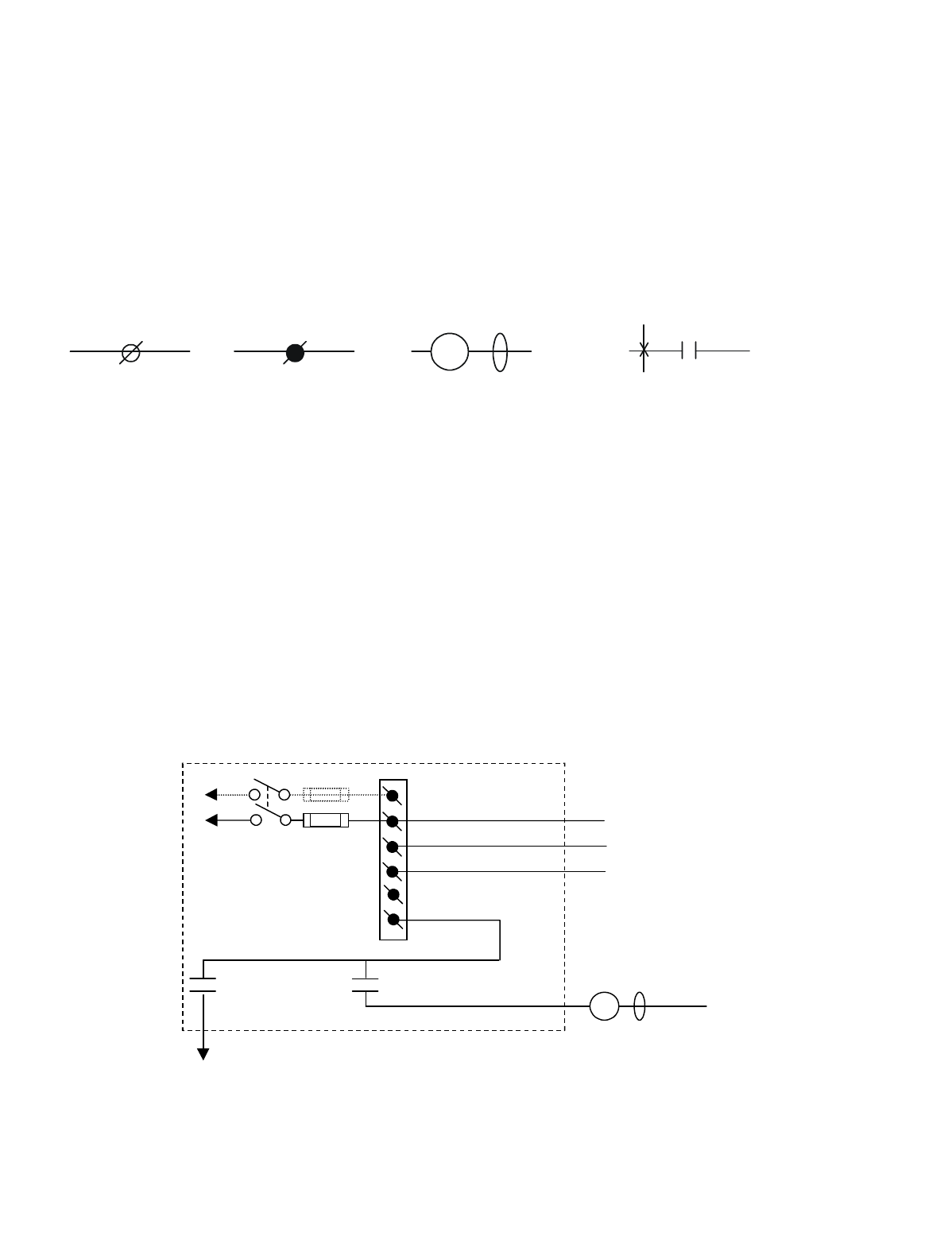
Appendix A - 10K12/18 Pendant and SLTX
Transmitter Programming (Continued)
A-4
A-5. Tables 1(a) through (k) Wiring and
Programming Diagrams
The following tables give various extended crane configura-
tions. Functional terms like Trolley East and Hoist Up
match standard transmitter labeling from the factory. The
following legend is used in these diagrams:
In the following wiring diagrams the relay outputs AJ2, BJ2
and CJ2 have listed to the right of the outer terminal, the
appropriate motor function they control, i.e., trolley, hoist
etc. Proper installation requires that this output be wired to
a contactor controlling that function and that the contactor
has the proper arc suppressor across it. The relays on these
output boards are rated at 16 amps and fused at 10 amps
unless otherwise noted.
A-6. Optional 120 Volt Wiring
Power supply wiring is accomplished through connector J1
on the power supply board. The connections labeled 240,
120, N and GND are wired to the appropriate supply con-
nections per the wiring diagrams. An extra connection 120
is provided for 120 Volt applications only for jumpering to
Pins 2 and 6 of the Master Relay (MR) K1 on the power
supply board. The unit may optionally be wired as in Figure
A-1. Figure A-2 shows the wiring layout. All other wiring
is accomplished per the tables.
Figure A-1. Optional 120 VAC Wiring Diagram
#
Indicates terminal
block J2 or J3 with
terminal number #
in the radio receiver
output board
GND
Indicates terminal
block J1 in power
supply board with
the required con-
nection noted.
Indicates customer
supplied contactor coil
with arc suppressor in
parallel.
MLC
Indicates a relay contact in radio
receiver number #. The X
indicates the relay closing and the
closing sequence (1
st
, 2
nd
, etc.) as
the indicated switch is de
p
ressed.
K#
1
S
T
SW1
ON/OFF
E10171-X
P/S BOARD
(2)
K1 (M R)
(4)
•
•
120
FUSE J1
N
GND
N
120
(6)
K1 (M R)
(8)
•
•
•
120 VAC
MLC
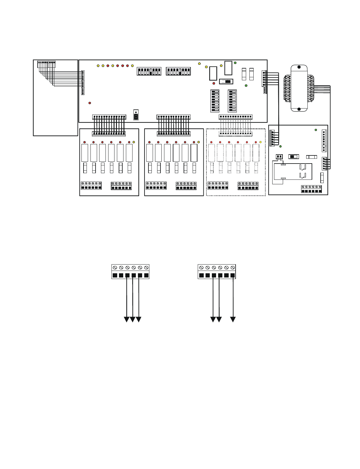
Appendix A - 10K12/18 Pendant and SLTX
Transmitter Programming (Continued)
A-5
Figure A-2. 10K12 Wiring Layout
A-7. Crane Control Type Selection
The crane control type selection information is provided in
TABLE 1(a) through TABLE 1(l). Each table defines a spe-
cific configuration and provides a wiring diagram, a pro-
gramming diagram, and transmitter and receiver switch
settings. The table for each configuration is provided on
facing pages so that all information is easily accessible.
J1 Power Supply
Board
NGNDN120 240120
Ground
Neutral
120VAC
NGNDN120 240120
Ground
240VAC B
240VAC A
220 VAC Wirin
g
110 VAC Wirin
g
J5
F2
DS2
DS
1SW1
ON OFF
J2
J3 J7
POWER
SUPPLY
BOARD
DS1
K1
F1
J2
1 2 3 4 5 6 1 2 3 4 5 6
J3
F2 F3 F4 F5 F6
K2 K3 K4 K5 K6
DS2 DS3 DS4 DS5 DS6
DS
7
J1
RELAY BOARD
RECEIVER BOARD
DS1
K1
F1
J2
1 2 3 4 5 6 1 2 3 4 5 6
J3
F2 F3 F4 F5 F6
K2 K3 K4 K5 K6
DS2 DS3 DS4 DS5 DS6
DS
7
J1
RELAY BOARD
T
R
A
N
S
F
O
R
M
E
R
J3
J4
DS-15
DS2
K
1
S1
DS5
DS4 DS1
DS3
J7 J8 J6
87654321
87654 321
0FF 0FF
S3 S2
0FF
87654 321
S5
87654321
S4
0FF
DS-7 -8 -9 -10 -11-12 -13-14
J5
JU2
J2
J1
K
2
DS6
ON
CPU BOARD
F1
J6
J1
NGNDN120 240120
2
86
4
MASTER
CONTROL
RELAY
(MCR)
K1
OUTPUTS INPUTS OUTPUTS INPUTS OUTPUTS INPUTS
Position A Position B Position C
BA
F2 F1
DS1
K1
F1
J2
1 2 3 4 5 6 1 2 3 4 5 6
J3
F2 F3 F4 F5 F6
K2 K3 K4 K5 K6
DS2 DS3 DS4 DS5 DS6
DS
7
J1
RELAY BOARD
OPTIONAL OUTPUT BOARD
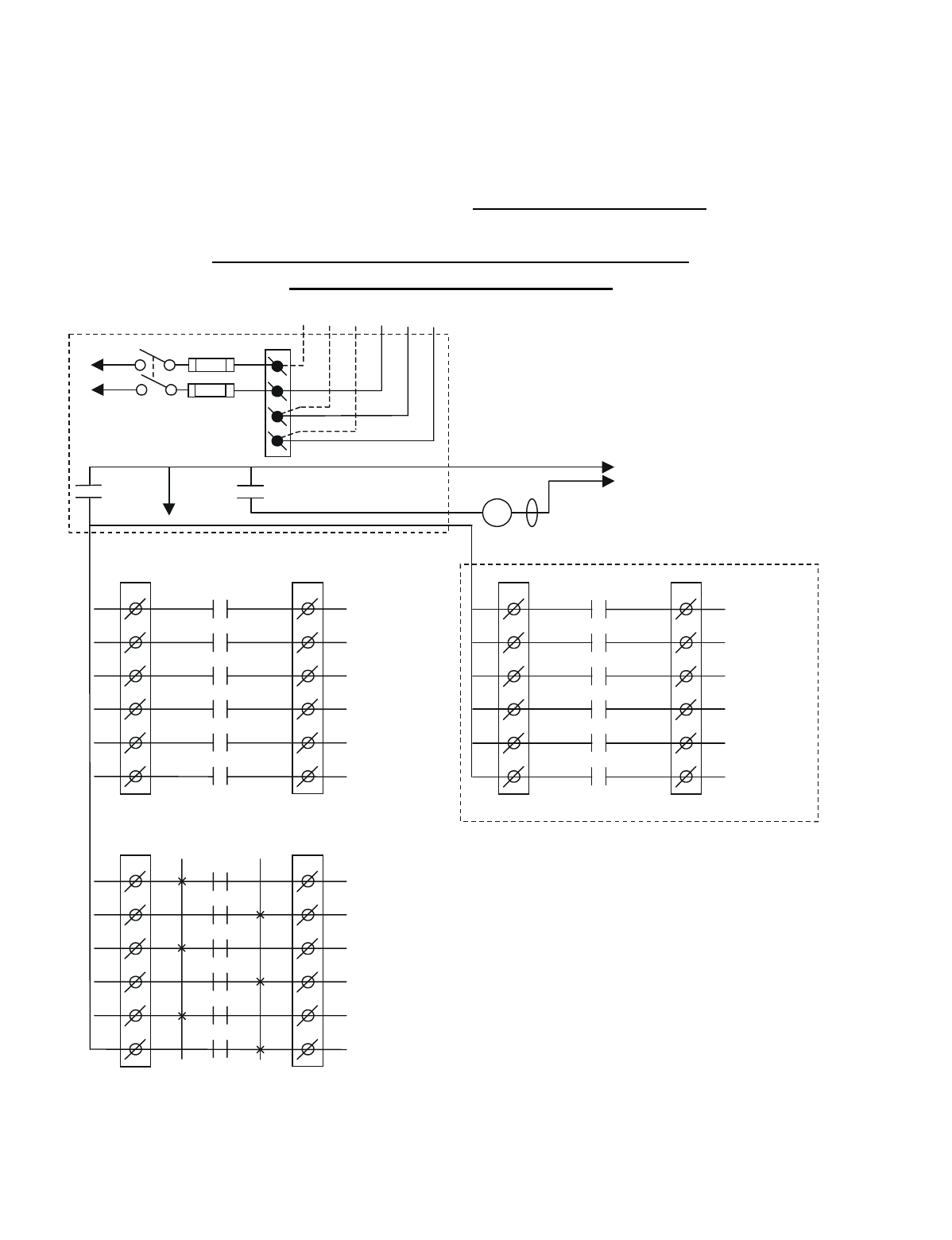
Appendix A - 10K12/18 Pendant and SLTX
Transmitter Programming (Continued)
A-6
TABLE 1(a)
Crane Control Type Selection: 10K12 Single Speed TYPE 0 WIRING DIAGRAM
____________________________________________________________________________________________________
STANDARD CONFIGURATION: ALL MOTIONS
(HOIST, TROLLEY and BRIDGE)
BJ3
1
2
3
4
5
6
BJ2
1
2
3
4
5
6
K1
K2
K3
K4
K5
K6
11
HOIST
UP
HOIST
DOWN
BRIDGE
NORTH
BRIDGE
SOUTH
TROLLEY
EAST
TROLLEY
WEST
•
•
•
•
•
*NOTE:
If it is necessary to operate the Alarm
Function during E-Stop condition, wire the input to the
alarm relay “J3” for the alarm function to the control
power hot side (relay “K1” (MR) on P/S Board de-
energized).
M ultibox outputs available with factory
installed Multibox option only.
All connections to outputs AJ2, BJ2 and
CJ2 are to contactors, with proper arc
suppressors across them, controlling the
appropriate listed function to the right.
Telemotive receiver output boards
(E10165-X).
240 VAC 120 VAC
SW1
ON/OFF
TO POWER
TRANSFORMER
E10171-X
P/S BOARD
MAIN LINE
CONTACTOR
TO
CONTROL
POWER
HOT
RET
(2)
K1 (M R)
(4)
•
•
•
*
See Note
•
240
120
FUSE J1
N
GND
(6)
K1 (M R)
(8)
•
•
•
AJ3
1
2
3
4
5
6
AJ2
1
2
3
4
5
6
K1
K2
K3
K4
K5
K6
AUX 5
AUX 6
AUX 4
AUX 3
AUX 2
AUX 1
•
•
•
•
•
•
CJ3
1
2
3
4
5
6
CJ2
1
2
3
4
5
6
K1
K2
K3
K4
K5
K6
OPTIONAL
MULTIBOX 1
MULTIBOX 2
MULTIBOX 3
MULTIBOX 4
•
•
•
•
•
MLC
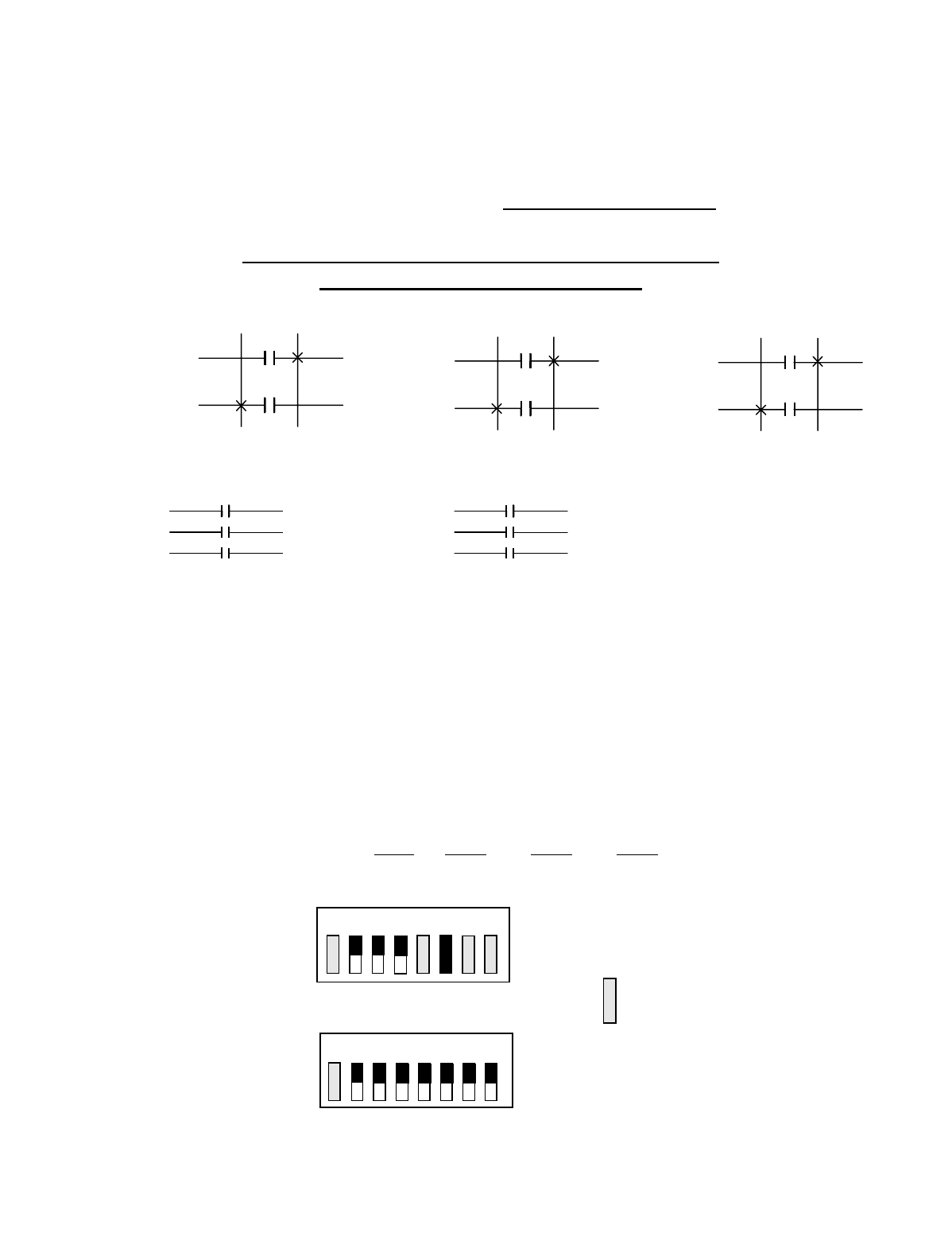
Appendix A - 10K12/18 Pendant and SLTX
Transmitter Programming (Continued)
A-7
TABLE 1(a)
Crane Control Type Selection: 10K12 Single Speed TYPE 0 PROGRAMMING
____________________________________________________________________________________________________
STANDARD CONFIGURATION: ALL MOTIONS
(HOIST, TROLLEY and BRIDGE)
STANDARD STANDARD OPTIONAL OUTPUT
OUTPUTS OUTPUTS BOARD OPTION #1
A1 AUX 5 (LATCHABLE S2-7) B1 HOIST UP C1
A2 AUX 6 (LATCHABLE S2-6) B2 HOIST DOWN C2
A3 AUX 4 B3 BRIDGE NORTH C3 MULTIBOX 1
A4 AUX 3 B4 BRIDGE SOUTH C4 MULTIBOX 2
A5 AUX 2 B5 TROLLEY EAST C5 MULTIBOX 3
A6 AUX 1 B6 TROLLEY WEST C6 MULTIBOX 4
Transmitter and Receiver Switch Select: Switch settings
Sw3-5 to Sw3-7 are defined as follows (for Optional Output
Board in the Receiver Sw3-3 must be “ON” for Option #1
and “OFF” for Option #1):
TRANSMITTER SWITCH SETTINGS: TYPE Sw4-7 Sw4-6 Sw4-5
0 OFF OFF OFF
OUTPUTS
B2
B1
HOIST
OUTPUTS
B4
B3
BRIDGE
OUTPUTS
B6
B5
TROLLEY
A6
A5
A4
AUX 1
AUX 2
AUX 3
1ST 1ST 1ST 1ST
UP DN N S E W
INDEPENDENT OUTPUTS
1ST 1ST
A3
A2
A1
AUX 4
AUX 6
AUX 5
OFF
ON
Sw4
Sw3 OFF
ON
For these switch
positions see the
beginning of this
section.
18234567
18234567
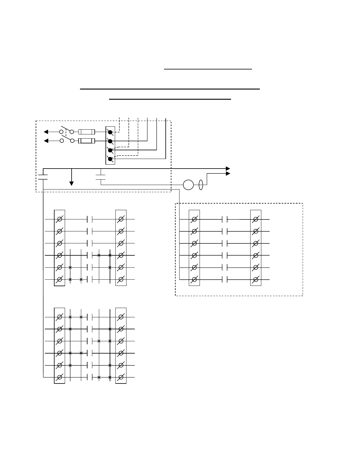
Appendix A - 10K12/18 Pendant and SLTX
Transmitter Programming (Continued)
A-8
TABLE 1(b)
Crane Control Type Selection: 10K12 2-Speed TYPE 0 WIRING DIAGRAM
____________________________________________________________________________________________________
STANDARD CONFIGURATION: ALL MOTIONS
(HOIST, TROLLEY and BRIDGE)
BJ3
1
2
3
4
5
6
BJ2
1
2
3
4
5
6
K1
K2
K3
K4
K5
K6
2 1 1 2
HOIST
UP
HOIST
2
ND
SPD
HOIST
DOWN
BRIDGE
NORTH
BRIDGE
2
ND
SPD
BRIDGE
SOUTH
•
•
•
•
•
*NOTE:
If it is necessary to operate the Alarm
Function during E-Stop condition, wire the input to the
alarm relay “AJ3-1” for the alarm function to the
control power hot side (relay “K1” (MR) on P/S Board
de-energized).
Telemotive receiver output boards
(E10165-X).
Multibox outputs available with factory
installed Multibox option only.
All connections to outputs AJ2, BJ2 and
CJ2 are to contactors, with proper arc
suppressors across them, controlling the
appropriate listed function to the right.
**Aux outputs 4 and 5 available with
Multibox. Aux outputs 4 to 6 available
with Multibox disabled. Aux 5 and 6
require a special transmitter see your
Telemotive representative.
240 VAC 120 VAC
SW1
ON/OFF
TO POWER
TRANSFORMER
E10171-X
P/S BOARD
MAIN LINE
CONTACTOR
TO
CONTROL
POWER
MLC
HOT
RET
(2)
K1 (MR)
(4)
•
•
•
*
See Note
•
240
120
FUSE J1
N
GND
(6)
K1 (MR)
(8)
•
•
•
AJ3
1
2
3
4
5
6
AJ2
1
2
3
4
5
6
K1
K2
K3
K4
K5
K6
2 1 1 2
AUX 3
(*ALARM)
AUX 2
AUX 1
TROLLEY
WEST
TROLLEY
2
ND
SPD
TROLLEY
EAST
•
•
•
•
•
•
CJ3
1
2
3
4
5
6
CJ2
1
2
3
4
5
6
K1
K2
K3
K4
K5
K6
OPTIONAL
**AUX 4
**AUX 5
MULTIBOX 1
OR **AUX 6
MULTIBOX 2
MULTIBOX 3
MULTIBOX 4
•
•
•
•
•
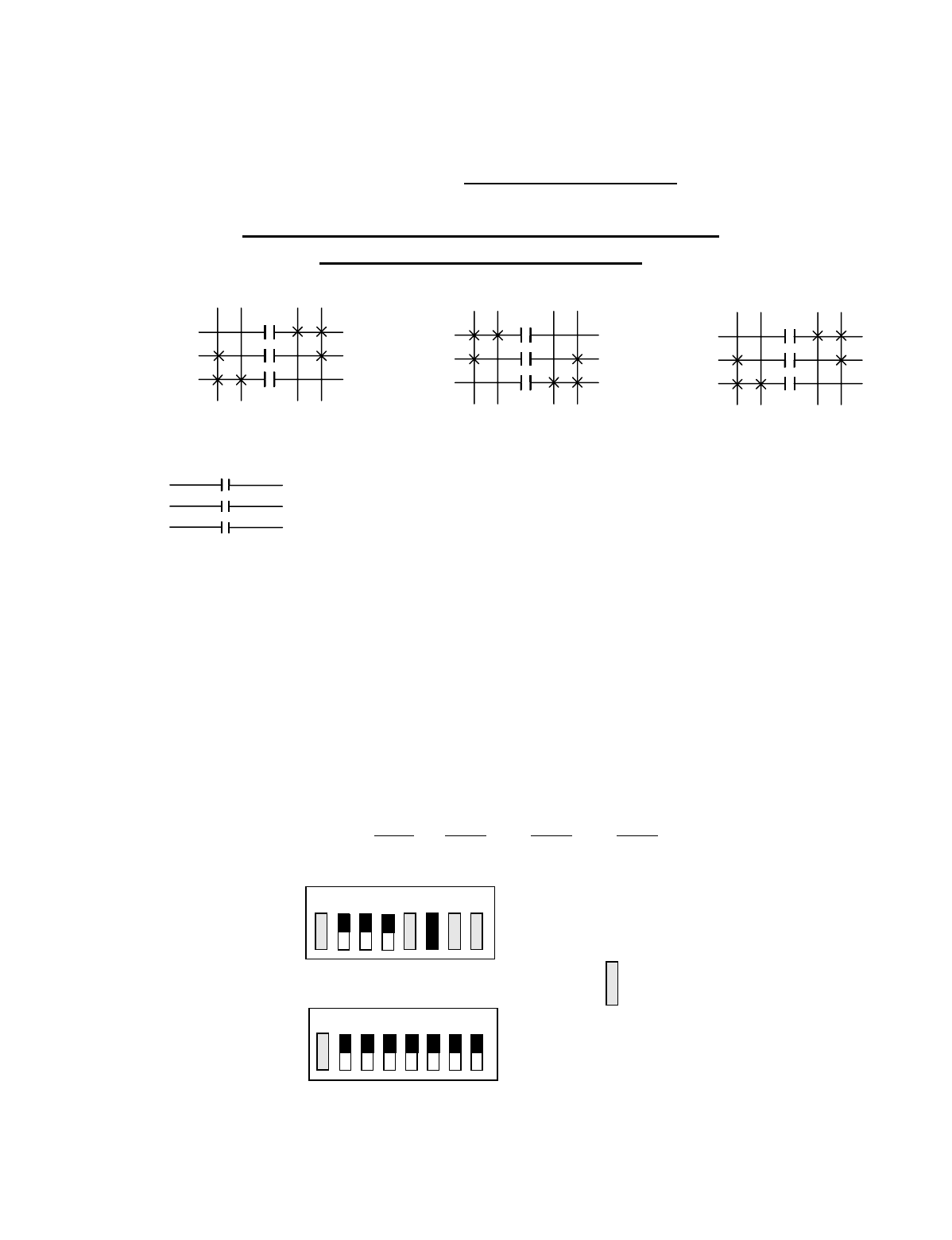
Appendix A - 10K12/18 Pendant and SLTX
Transmitter Programming (Continued)
A-9
TABLE 1(b)
Crane Control Type Selection: 10K12 2-Speed TYPE 0 PROGRAMMING
____________________________________________________________________________________________________
STANDARD CONFIGURATION: ALL MOTIONS
(HOIST, TROLLEY and BRIDGE)
STANDARD STANDARD OPTIONAL OUTPUT OPTIONAL OUTPUT
OUTPUTS OUTPUTS BOARD OPTION #1 BOARD OPTION #2
A1 AUX 3 (ALARM) B1 HOIST UP C1 AUX 4 C1 AUX 4
A2 AUX 2 (LATCHABLE S2-6) B2 HOIST 2ND SPEED C2 AUX 5 C2 AUX 5
A3 AUX 1 (LATCHABLE S2-7) B3 HOIST DOWN C3 MULTIBOX 1 C3 AUX 6
A4 TROLLEY WEST B4 BRIDGE NORTH C4 MULTIBOX 2 C4
A5 TROLLEY 2ND SPEED B5 BRIDGE 2ND SPEED C5 MULTIBOX 3 C5
A6 TROLLEY EAST B6 BRIDGE SOUTH C6 MULTIBOX 4 C6
Transmitter and Receiver Switch Select: Switch settings
Sw3-5 to Sw3-7 are defined as follows (for Optional Output
Board in the Receiver Sw3-3 must be “ON” for Option #1
and “OFF” for Option #2):
TRANSMITTER SWITCH SETTINGS: TYPE Sw4-7 Sw4-6 Sw4-5
0 OFF OFF OFF
OUTPUTS
B3
B2
B1
HOIST
OUTPUTS
A6
A5
A4
TROLLEY
OUTPUTS
B6
B5
B4
BRIDGE
A3
A2
A1
AUX 1
AUX 2
AUX 3 ALARM
2ND 1ST 1ST 2ND 1ST 2ND 1ST 2ND
UP DN E W N S
INDEPENDENT OUTPUTS
2ND 1ST 2ND 1ST
OFF
ON
Sw4
Sw3 OFF
ON
For these switch
positions see the
beginning of this
section.
18234567
18234567
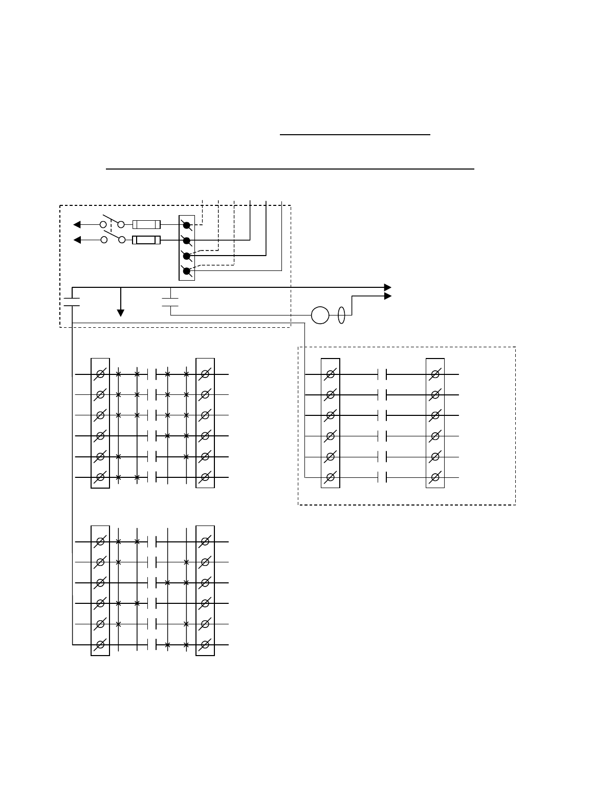
Appendix A - 10K12/18 Pendant and SLTX
Transmitter Programming (Continued)
A-10
TABLE 1(c)
Crane Control Type Selection: 10K12 2-Speed TYPE 1 WIRING DIAGRAM
____________________________________________________________________________________________________
2-SPEED with DIRECTIONAL CONTROL: ALL MOTIONS
BJ3
1
2
3
4
5
6
BJ2
1
2
3
4
5
6
K1
K2
K3
K4
K5
K6
2 1 1 2
HOIST
UP
HOIST
2
ND
SPD
HOIST
DOWN
BRIDGE
NORTH
BRIDGE
2
ND
SPD
BRIDGE
SOUTH
•
•
•
•
•
*NOTE:
If it is necessary to operate the Alarm
Function during E-Stop condition, wire the input to the
alarm relay “J3” for the alarm function to the control
power hot side (relay “K1” (MR) on P/S Board de-
energized).
Telemotive receiver output boards
(E10165-X).
Multibox outputs available with factory
installed Multibox option only.
All connections to outputs AJ2, BJ2 and
CJ2 are to contactors, with proper arc
suppressors across them, controlling the
appropriate listed function to the right.
**Aux outputs 4 and 3 available with
Multibox. Aux outputs 1 to 6 available
with Multibox disabled. Aux 5 and 6
require a special transmitter see your
Telemotive representative.
240 VAC 120 VAC
SW1
ON/OFF
TO POWER
TRANSFORMER
E10171-X
P/S BOARD
MAIN LINE
CONTACTOR
TO
CONTROL
POWER
HOT
RET
(2)
K1 (MR)
(4)
•
•
•
*
See Note
•
240
120
FUSE J1
N
GND
(6)
K1 (MR)
(8)
•
•
•
AJ3
1
2
3
4
5
6
AJ2
1
2
3
4
5
6
2 1 1 2
HOIST
UP/DOWN
TROLLEY
EAST/WEST
BRIDGE
NORTH/SOUTH
TROLLEY
WEST
TROLLEY
2
ND
SPD
TROLLEY
EAST
•
•
•
•
•
•
CJ3
1
2
3
4
5
6
CJ2
1
2
3
4
5
6
K1
K2
K3
K4
K5
K6
OPTIONAL
**AUX 4
**AUX 3
MULTIBOX 1
**or AUX 2
MULTIBOX 2
**or AUX 1
MULTIBOX 3
**or AUX 5
MULTIBOX 4
**or AUX 6
•
•
•
•
•
K1
K2
K3
K4
K5
K6
MLC
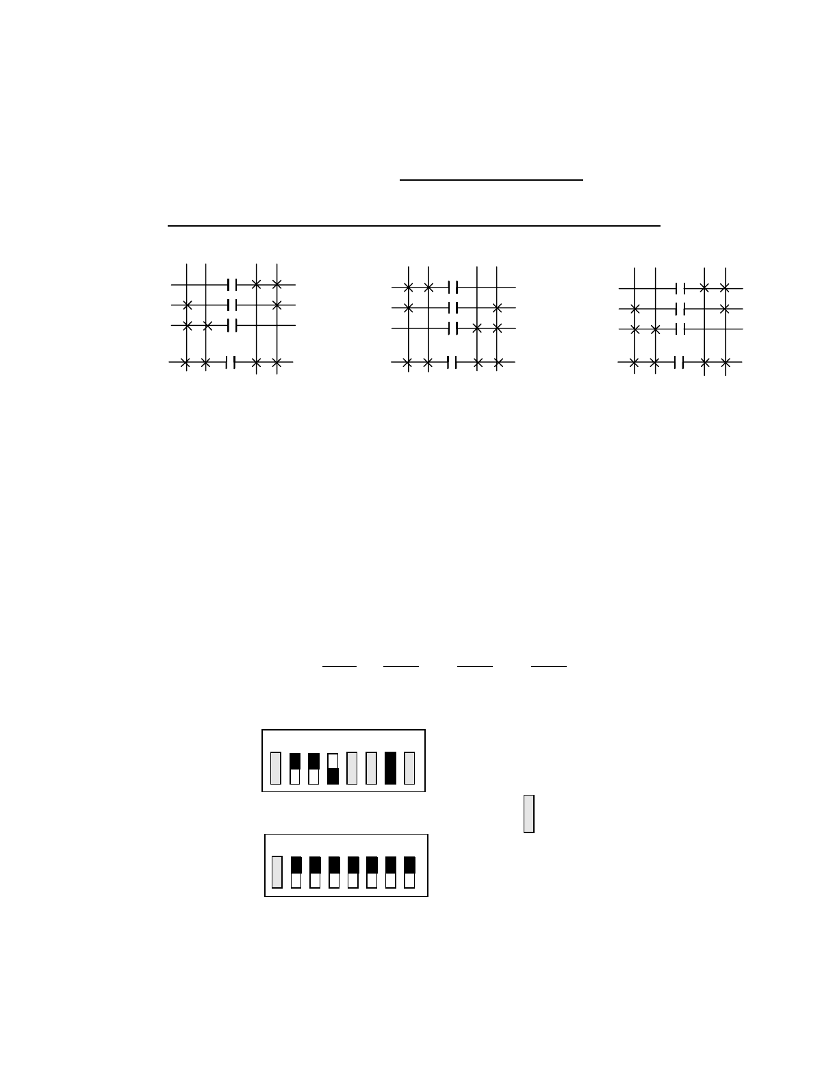
Appendix A - 10K12/18 Pendant and SLTX
Transmitter Programming (Continued)
A-11
TABLE 1(c)
Crane Control Type Selection: 10K12 2-Speed TYPE 1 PROGRAMMING
____________________________________________________________________________________________________
2-SPEED with DIRECTIONAL CONTROL: ALL MOTIONS
STANDARD STANDARD OPTIONAL OUTPUT OPTIONAL OUTPUT
OUTPUTS OUTPUTS BOARD OPTION #1 BOARD OPTION #2
A1 HOIST UP/DOWN B1 HOIST UP C1 AUX 4 C1 AUX 4
A2 TROLLEY EAST/WEST B2 HOIST 2ND SPEED C2 AUX 3 C2 AUX 3
A3 BRIDGE NORTH/SOUTH B3 HOIST DOWN C3 MULTIBOX 1 C3 AUX 2
A4 TROLLEY WEST B4 BRIDGE NORTH C4 MULTIBOX 2 C4 AUX 1
A5 TROLLEY 2ND SPEED B5 BRIDGE 2ND SPEED C5 MULTIBOX 3 C5 AUX 5
A6 TROLLEY EAST B6 BRIDGE SOUTH C6 MULTIBOX 4 C6 AUX 6
Transmitter and Receiver Switch Select: Switch settings
Sw3-5 to Sw3-7 are defined as follows (for Optional Output
Board in the Receiver Sw3-3 must be “ON” for Option #1
and “OFF” for Option #2):
TRANSMITTER SWITCH SETTINGS: TYPE Sw4-7 Sw4-6 Sw4-5
1OFF OFF ON
OUTPUTS
B3
B2
B1
A1
HOIST
OUTPUTS
A6
A5
A4
A2
TROLLEY
OUTPUTS
B6
B5
B4
A3
BRIDGE
1ST 2ND 1ST 2ND 1ST 2ND
UP DN E W N S
2ND 1ST 2ND 1ST 2ND 1ST
OFF
ON
Sw4
Sw3 OFF
ON
For these switch
positions see the
beginning of this
section.
18234567
18234567
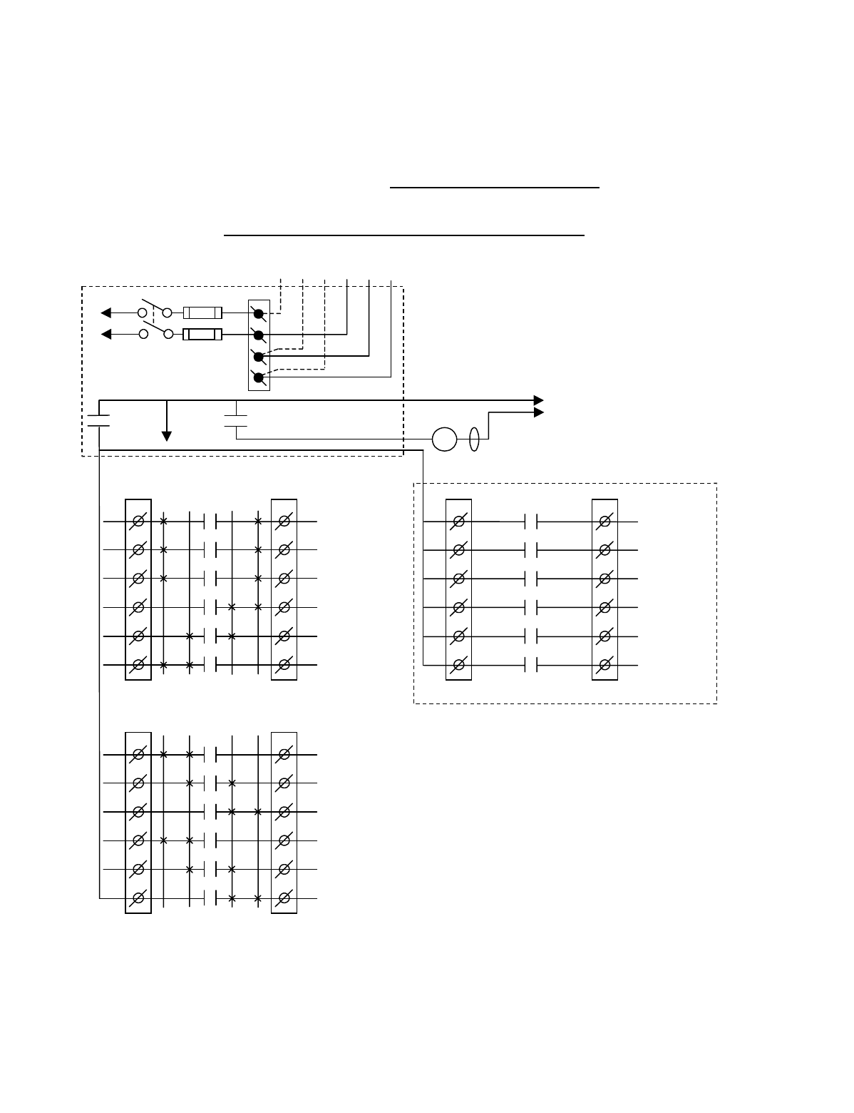
Appendix A - 10K12/18 Pendant and SLTX
Transmitter Programming (Continued)
A-12
TABLE 1(d)
Crane Control Type Selection: 10K12 2-Speed TYPE 2 WIRING DIAGRAM
____________________________________________________________________________________________________
2-SPEED, 2-WINDINGS: ALL MOTIONS
BJ3
1
2
3
4
5
6
BJ2
1
2
3
4
5
6
K1
K2
K3
K4
K5
K6
2 1 1 2
HOIST
UP
HOIST
LOW SPD
HOIST
DOWN
BRIDGE
NORTH
BRIDGE
LOW SPD
BRIDGE
SOUTH
•
•
•
•
•
*NOTE:
If it is necessary to operate the Alarm
Function during E-Stop condition, wire the input to the
alarm relay “J3” for the alarm function to the control
power hot side (relay “K1” (MR) on P/S Board de-
energized).
Telemotive receiver output boards
(E10165-X).
Multibox outputs available with factory
installed Multibox option only.
All connections to outputs AJ2, BJ2 and
CJ2 are to contactors, with proper arc
suppressors across them, controlling the
appropriate listed function to the right.
**Aux outputs 4 and 3 available with
Multibox. Aux outputs 1 to 6 available
with Multibox disabled. Aux 5 and 6
require a special transmitter see your
Telemotive representative.
240 VAC 120 VAC
SW1
ON/OFF
TO POWER
TRANSFORMER
E10171-X
P/S BOARD
MAIN LINE
CONTACTOR
TO
CONTROL
POWER
HOT
RET
(2)
K1 (MR)
(4)
•
•
•
*
See Note
•
240
120
FUSE J1
N
GND
(6)
K1 (MR)
(8)
•
•
•
AJ3
1
2
3
4
5
6
AJ2
1
2
3
4
5
6
2 1 1 2
HOIST
HIGH SPD
TROLLEY
HIGH SPD
BRIDGE
HIGH SPD
TROLLEY
WEST
TROLLEY
LOW SPD
TROLLEY
EAST
•
•
•
•
•
•
CJ3
1
2
3
4
5
6
CJ2
1
2
3
4
5
6
K1
K2
K3
K4
K5
K6
OPTIONAL
**AUX 4
**AUX 3
MULTIBOX 1
**or AUX 2
MULTIBOX 2
**or AUX 1
MULTIBOX 3
**or AUX 5
MULTIBOX 4
**or AUX 6
•
•
•
•
•
K1
K2
K3
K4
K5
K6
MLC
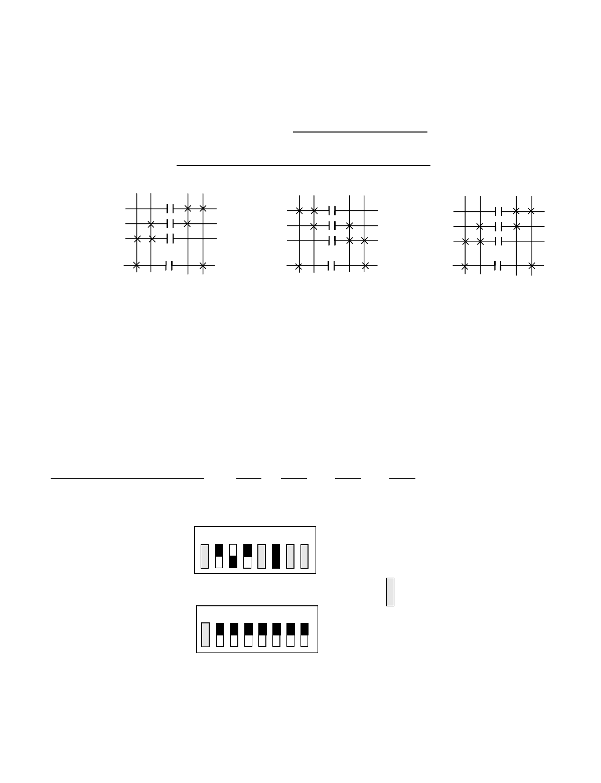
Appendix A - 10K12/18 Pendant and SLTX
Transmitter Programming (Continued)
A-13
TABLE 1(d)
Crane Control Type Selection: 10K12 2-Speed TYPE 2 PROGRAMMING
____________________________________________________________________________________________________
2-SPEED, 2-WINDINGS: ALL MOTIONS
STANDARD STANDARD OPTIONAL OUTPUT OPTIONAL OUTPUT
OUTPUTS OUTPUTS BOARD OPTION #1 BOARD OPTION #2
A1 HOIST HIGH SPEED B1 HOIST UP C1 AUX 4 C1 AUX 4
A2 TROLLEY HIGH SPEED B2 HOIST LOW SPEED C2 AUX 3 C2 AUX 3
A3 BRIDGE HIGH SPEED B3 HOIST DOWN C3 MULTIBOX 1 C3 AUX 2
A4 TROLLEY WEST B4 BRIDGE NORTH C4 MULTIBOX 2 C4 AUX 1
A5 TROLLEY 2ND SPEED B5 BRIDGE LOW SPEED C5 MULTIBOX 3 C5 AUX 5
A6 TROLLEY EAST B6 BRIDGE SOUTH C6 MULTIBOX 4 C6 AUX 6
Transmitter and Receiver Switch Select: Switch settings
Sw3-5 to Sw3-7 are defined as follows (for Optional Output
Board in the Receiver Sw3-3 must be “ON” for Option #1
and “OFF” for Option #2):
TRANSMITTER SWITCH SETTINGS: TYPE Sw4-7 Sw4-6 Sw4-5
2 OFF ON OFF
OUTPUTS
B3
B2
B1
A1
HOIST
OUTPUTS
A6
A5
A4
A2
TROLLEY
OUTPUTS
B6
B5
B4
A3
BRIDGE
1ST 2ND 1ST 2ND 1ST 2ND
UP DN E W N S
2ND 1ST 2ND 1ST 2ND 1ST
OFF
ON
Sw4
Sw3 OFF
ON
For these switch
positions see the
beginning of this
section.
18234567
18234567
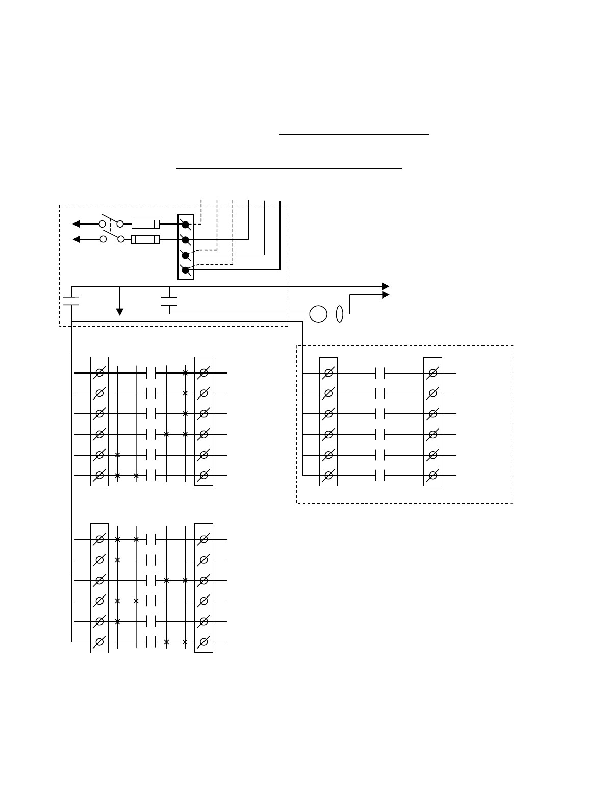
Appendix A - 10K12/18 Pendant and SLTX
Transmitter Programming (Continued)
A-14
TABLE 1(e)
Crane Control Type Selection: 10K12 2-Speed TYPE 3 WIRING DIAGRAM
____________________________________________________________________________________________________
ACCO CONTROLS: ALL MOTIONS
BJ3
1
2
3
4
5
6
BJ2
1
2
3
4
5
6
K1
K2
K3
K4
K5
K6
2 1 1 2
HOIST
UP
HOIST UP
2
ND
SPD
HOIST
DOWN
BRIDGE
NORTH
BRIDGE NORTH
2
ND
SPD
BRIDGE
SOUTH
•
•
•
•
•
*NOTE:
If it is necessary to operate the Alarm
Function during E-Stop condition, wire the input to the
alarm relay “J3” for the alarm function to the control
power hot side (relay “K1” (MR) on P/S Board de-
energized).
Telemotive receiver output boards
(E10165-X).
Multibox outputs available with factory
installed Multibox option only.
All connections to outputs AJ2, BJ2 and
CJ2 are to contactors, with proper arc
suppressors across them, controlling the
appropriate listed function to the right.
**Aux outputs 4 and 3 available with
Multibox. Aux outputs 1 to 6 available
with Multibox disabled. Aux 5 and 6
require a special transmitter see your
Telemotive representative.
240 VAC 120 VAC
SW1
ON/OFF
TO POWER
TRANSFORMER
E10171-X
P/S BOARD
MAIN LINE
CONTACTOR
TO
CONTROL
POWER
HOT
RET
(2)
K1 (MR)
(4)
•
•
•
*
See Note
•
240
120
FUSE J1
N
GND
(6)
K1 (MR)
(8)
•
•
•
AJ3
1
2
3
4
5
6
AJ2
1
2
3
4
5
6
2 1 1 2
HOIST DOWN
2
ND
SPD
TROLLEY WEST
2
ND
SPD
BRIDGE SOUTH
2
ND
SPD
TROLLEY
WEST
TROLLEY EAST
2
ND
SPD
TROLLEY
EAST
•
•
•
•
•
•
CJ3
1
2
3
4
5
6
CJ2
1
2
3
4
5
6
K1
K2
K3
K4
K5
K6
OPTIONAL
**AUX 4
**AUX 3
MULTIBOX 1
**or AUX 2
MULTIBOX 2
**or AUX 1
MULTIBOX 3
** or AUX 5
MULTIBOX 4
**or AUX 6
•
•
•
•
•
K1
K2
K3
K4
K5
K6
MLC
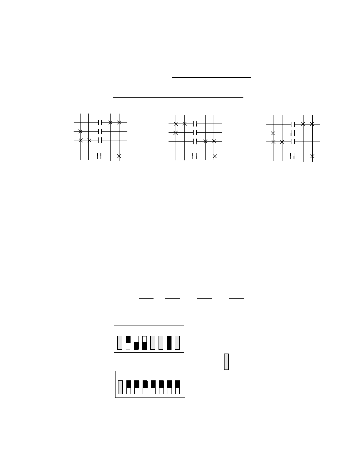
Appendix A - 10K12/18 Pendant and SLTX
Transmitter Programming (Continued)
A-15
TABLE 1(e)
Crane Control Type Selection: 10K12 2-Speed TYPE 3 PROGRAMMING
____________________________________________________________________________________________________
ACCO CONTROLS: ALL MOTIONS
STANDARD STANDARD OPTIONAL OUTPUT OPTIONAL OUTPUT
OUTPUTS OUTPUTS BOARD OPTION #1 BOARD OPTION #2
A1 HOIST DOWN 2ND SPEED B1 HOIST UP C1 AUX 4 C1 AUX 4
A2 TROLLEY WEST 2ND SPEED B2 HOIST UP 2ND SPEED C2 AUX 3 C2 AUX 3
A3 BRIDGE SOUTH 2ND SPEED B3 HOIST DOWN C3 MULTIBOX 1 C3 AUX 2
A4 TROLLEY WEST B4 BRIDGE NORTH C4 MULTIBOX 2 C4 AUX 1
A5 TROLLEY EAST 2ND SPEED B5 BRIDGE NORTH 2ND SPEED C5 MULTIBOX 3 C5 AUX 5
A6 TROLLEY EAST B6 BRIDGE SOUTH C6 MULTIBOX 4 C6 AUX 6
Transmitter and Receiver Switch Select: Switch settings
Sw3-5 to Sw3-7 are defined as follows (for Optional Output
Board in the Receiver Sw3-3 must be “ON” for Option #1
and “OFF” for Option #2):
TRANSMITTER SWITCH SETTINGS: TYPE Sw4-7 Sw4-6 Sw4-5
3 OFF ON ON
OUTPUTS
B3
B2
B1
A1
HOIST
OUTPUTS
A6
A5
A4
A2
TROLLEY
OUTPUTS
B6
B5
B4
A3
BRIDGE
1ST 2ND 1ST 2ND 1ST 2ND
UP DN E W N S
2ND 1ST 2ND 1ST 2ND 1ST
OFF
ON
Sw4
Sw3 OFF
ON
For these switch
positions see the
beginning of this
section.
18234567
18234567
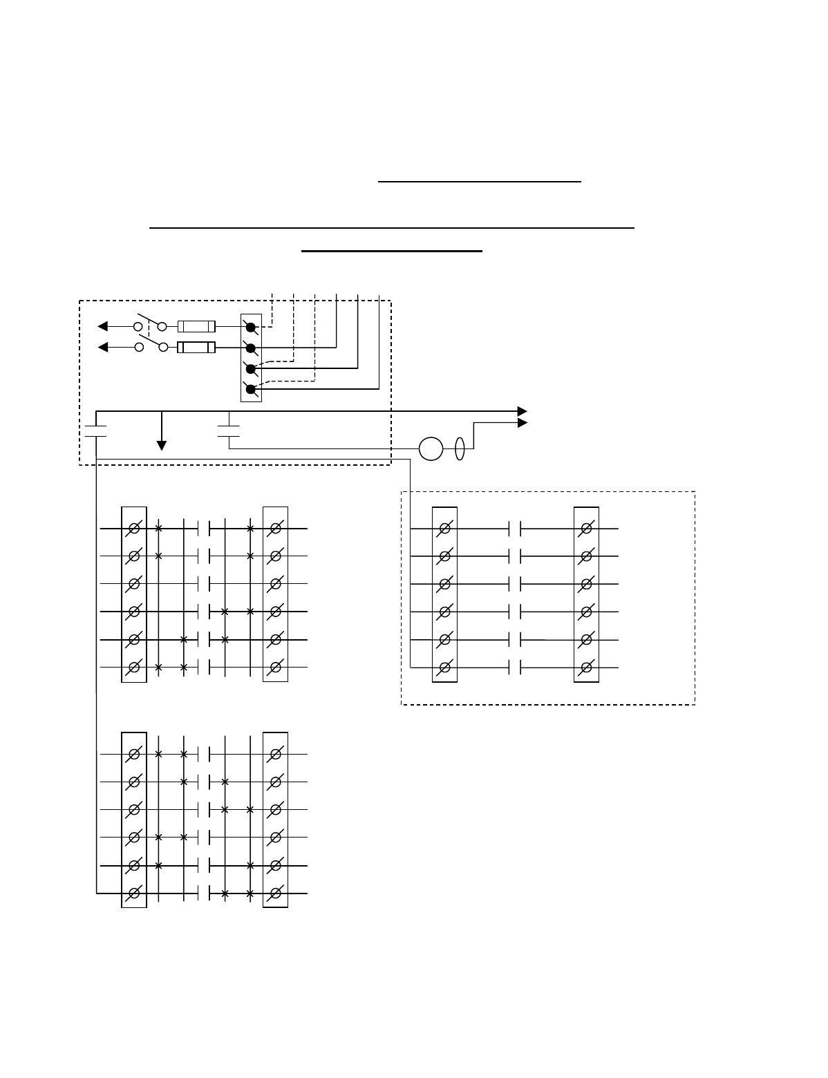
Appendix A - 10K12/18 Pendant and SLTX
Transmitter Programming (Continued)
A-16
TABLE 1(f)
Crane Control Type Selection: 10K12 2-Speed TYPE 4 WIRING DIAGRAM
____________________________________________________________________________________________________
P&H: 2-SPEED, 2-WINDINGS for HOIST and TROLLEY:
STANDARD BRIDGE
BJ3
1
2
3
4
5
6
BJ2
1
2
3
4
5
6
K1
K2
K3
K4
K5
K6
2 1 1 2
HOIST
UP
HOIST
LOW SPD
HOIST
DOWN
BRIDGE
NORTH
BRIDGE
2
ND
SPD
BRIDGE
SOUTH
•
•
•
•
•
*NOTE:
If it is necessary to operate the Alarm
Function during E-Stop condition, wire the input to the
alarm relay “J3” for the alarm function to the control
power hot side (relay “K1” (MR) on P/S Board de-
energized).
Telemotive receiver output boards
(E10165-X).
Multibox outputs available with factory
installed Multibox option only.
All connections to outputs AJ2, BJ2 and
CJ2 are to contactors, with proper arc
suppressors across them, controlling the
appropriate listed function to the right.
**Aux outputs 4 and 3 available with
Multibox. Aux outputs 2 to 6 available
with Multibox disabled. Aux 5 and 6
require a special transmitter see your
Telemotive representative.
240 VAC 120 VAC
SW1
ON/OFF
TO POWER
TRANSFORMER
E10171-X
P/S BOARD
MAIN LINE
CONTACTOR
TO
CONTROL
POWER
HOT
RET
(2)
K1 (MR)
(4)
•
•
•
*
See Note
•
240
120
FUSE J1
N
GND
(6)
K1 (MR)
(8)
•
•
•
AJ3
1
2
3
4
5
6
AJ2
1
2
3
4
5
6
2 1 1 2
HOIST
HIGH SPD
TROLLEY
HIGH SPD
AUX 1
TROLLEY
WEST
TROLLEY
LOW SPD
TROLLEY
EAST
•
•
•
•
•
•
CJ3
1
2
3
4
5
6
CJ2
1
2
3
4
5
6
K1
K2
K3
K4
K5
K6
OPTIONAL
**AUX 4
**AUX 3
MULTIBOX 1
**or AUX 2
MULTIBOX 2
**or AUX 5
MULTIBOX 3
**or AUX 6
MULTIBOX 4
•
•
•
•
•
K1
K2
K3
K4
K5
K6
MLC
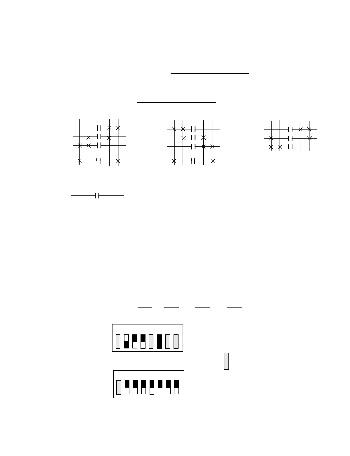
Appendix A - 10K12/18 Pendant and SLTX
Transmitter Programming (Continued)
A-17
TABLE 1(f)
Crane Control Type Selection: 10K12 2-Speed TYPE 4 PROGRAMMING
____________________________________________________________________________________________________
P&H: 2-SPEED, 2-WINDINGS for HOIST and TROLLEY:
STANDARD BRIDGE
STANDARD STANDARD OPTIONAL OUTPUT OPTIONAL OUTPUT
OUTPUTS OUTPUTS BOARD OPTION #1 BOARD OPTION #2
A1 HOIST HIGH SPEED B1 HOIST UP C1 AUX 4 C1 AUX 4
A2 TROLLEY HIGH SPEED B2 HOIST LOW SPEED C2 AUX 3 C2 AUX 3
A3 AUX 1 (LATCHABLE S2-7) B3 HOIST DOWN C3 MULTIBOX 1 C3 AUX 2
A4 TROLLEY WEST B4 BRIDGE NORTH C4 MULTIBOX 2 C4 AUX 5
A5 TROLLEY LOW SPEED B5 BRIDGE 2ND SPEED C5 MULTIBOX 3 C5 AUX 6
A6 TROLLEY EAST B6 BRIDGE SOUTH C6 MULTIBOX 4 C6
Transmitter and Receiver Switch Select: Switch settings
Sw3-5 to Sw3-7 are defined as follows (for Optional Output
Board in the Receiver Sw3-3 must be “ON” for Option #1
and “OFF” for Option #2):
TRANSMITTER SWITCH SETTINGS: TYPE Sw4-7 Sw4-6 Sw4-5
4ON OFFOFF
OUTPUTS
B3
B2
B1
A1
HOIST
OUTPUTS
A6
A5
A4
A2
TROLLEY
OUTPUTS
B6
B5
B4
BRIDGE
1ST 2ND 1ST 2ND
1ST 2ND
UP DN E W N S
A3 AUX 1
INDEPENDENT OUTPUTS
2ND 1ST 2ND 1ST
2ND 1ST
OFF
ON
Sw4
Sw3 OFF
ON
For these switch
positions see the
beginning of this
section.
18234567
18234567
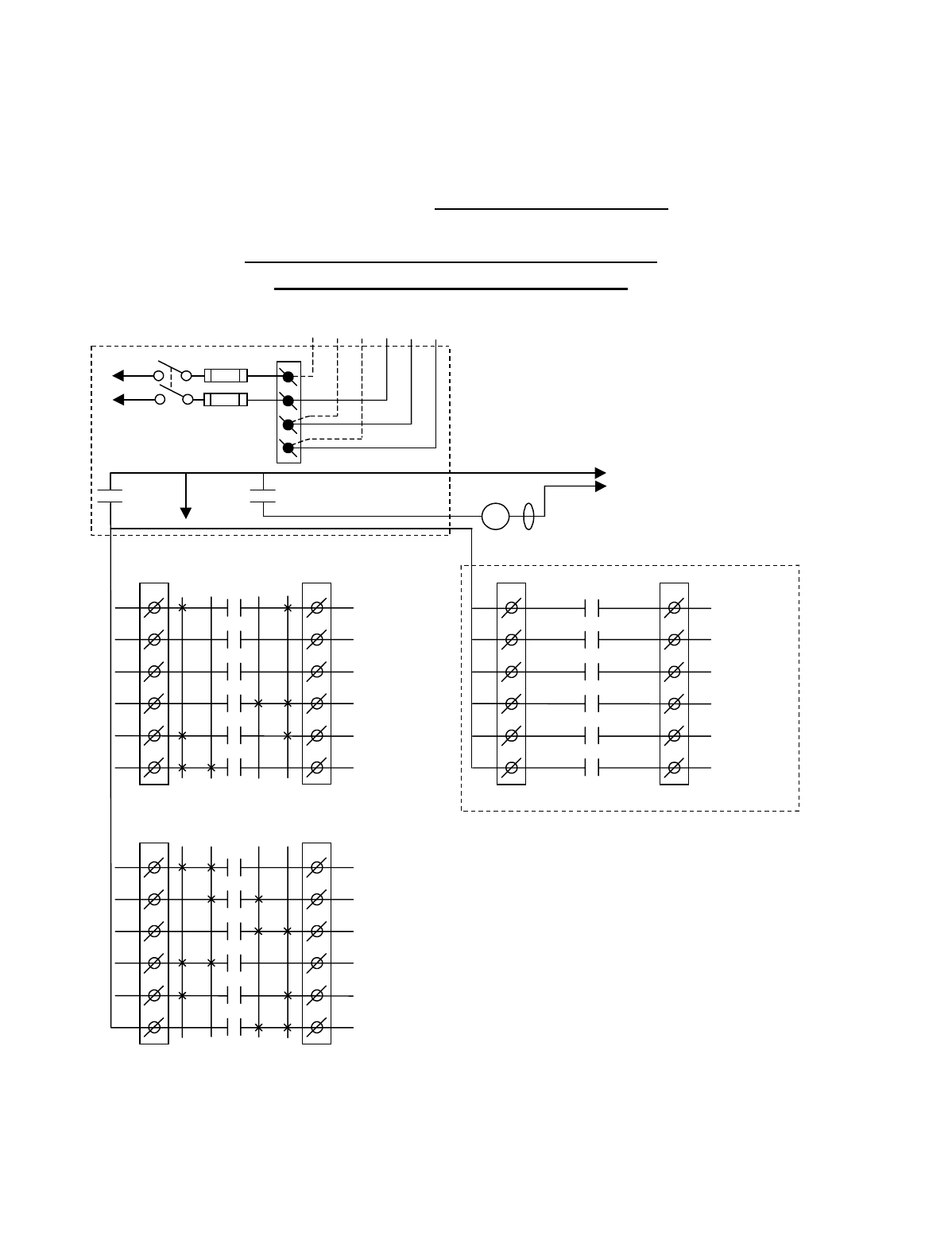
Appendix A - 10K12/18 Pendant and SLTX
Transmitter Programming (Continued)
A-18
TABLE 1(g)
Crane Control Type Selection: 10K12 2-Speed TYPE 5 WIRING DIAGRAM
____________________________________________________________________________________________________
P&H: 2-SPEED, 2-WINDINGS for HOIST:
STANDARD BRIDGE and TROLLEY
BJ3
1
2
3
4
5
6
BJ2
1
2
3
4
5
6
K1
K2
K3
K4
K5
K6
2 1 1 2
HOIST
UP
HOIST
LOW SPD
HOIST
DOWN
BRIDGE
NORTH
BRIDGE
2
ND
SPD
BRIDGE
SOUTH
•
•
•
•
•
*NOTE:
If it is necessary to operate the Alarm
Function during E-Stop condition, wire the input to the
alarm relay “J3” for the alarm function to the control
power hot side (relay “K1” (MR) on P/S Board de-
energized).
Telemotive receiver output boards
(E10165-X).
Multibox outputs available with factory
installed Multibox option only.
All connections to outputs AJ2, BJ2 and
CJ2 are to contactors, with proper arc
suppressors across them, controlling the
appropriate listed function to the right.
**Aux outputs 4 and 3 available with
Multibox. Aux outputs 3 to 6 available
with Multibox disabled. Aux 5 and 6
require a special transmitter see your
Telemotive representative.
240 VAC 120 VAC
SW1
ON/OFF
TO POWER
TRANSFORMER
E10171-X
P/S BOARD
MAIN LINE
CONTACTOR
TO
CONTROL
POWER
HOT
RET
(2)
K1 (MR)
(4)
•
•
•
*
See Note
•
240
120
FUSE J1
N
GND
(6)
K1 (MR)
(8)
•
•
•
AJ3
1
2
3
4
5
6
AJ2
1
2
3
4
5
6
2 1 1 2
HOIST
HIGH SPD
AUX 2
AUX 1
TROLLEY
WEST
TROLLEY
2
ND
SPD
TROLLEY
EAST
•
•
•
•
•
•
CJ3
1
2
3
4
5
6
CJ2
1
2
3
4
5
6
K1
K2
K3
K4
K5
K6
OPTIONAL
**AUX 4
**AUX 3
MULTIBOX 1
**or AUX 5
MULTIBOX 2
**or AUX 6
MULTIBOX 3
MULTIBOX 4
•
•
•
•
•
K1
K2
K3
K4
K5
K6
MLC
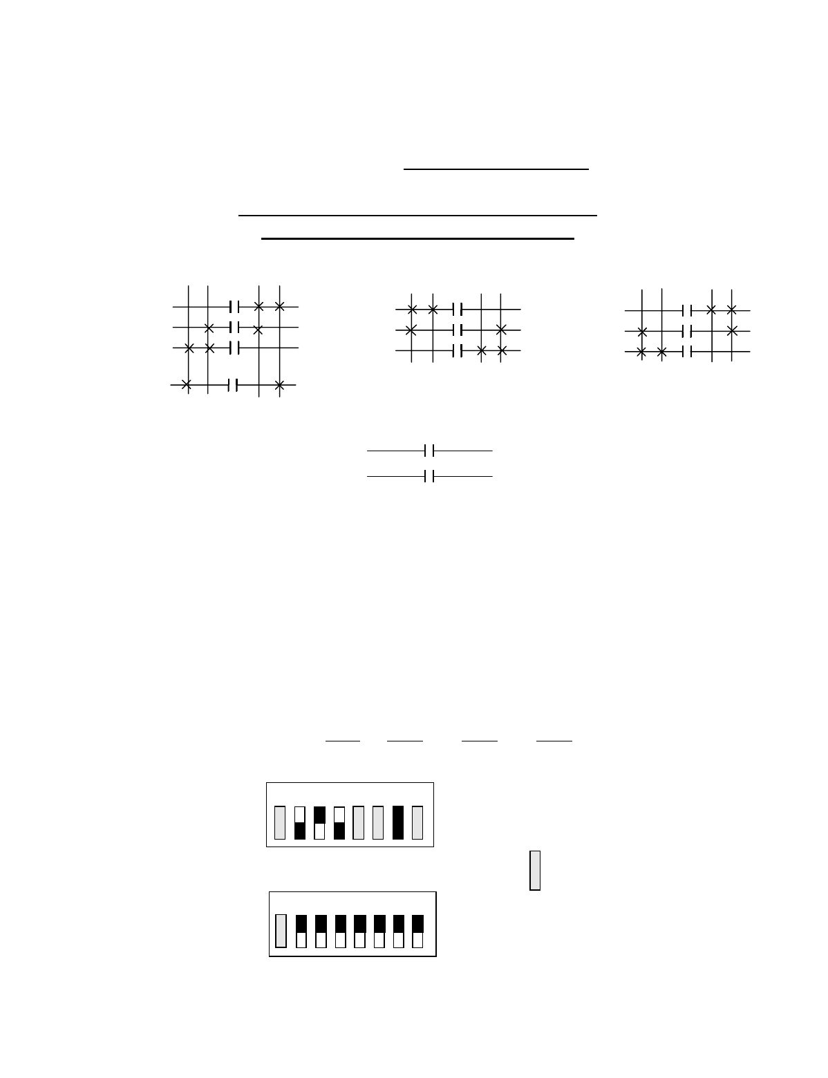
Appendix A - 10K12/18 Pendant and SLTX
Transmitter Programming (Continued)
A-19
TABLE 1(g)
Crane Control Type Selection: 10K12 2-Speed TYPE 5 PROGRAMMING
____________________________________________________________________________________________________
P&H: 2-SPEED, 2-WINDINGS for HOIST:
STANDARD BRIDGE and TROLLEY
STANDARD STANDARD OPTIONAL OUTPUT OPTIONAL OUTPUT
OUTPUTS OUTPUTS BOARD OPTION #1 BOARD OPTION #2
A1 HOIST HIGH SPEED B1 HOIST UP C1 AUX 4 C1 AUX 4
A2 AUX 2 (LATCHABLE S2-6) B2 HOIST LOW SPEED C2 AUX 3 C2 AUX 3
A3 AUX 1 (LATCHABLE S2-7) B3 HOIST DOWN C3 MULTIBOX 1 C3 AUX 5
A4 TROLLEY WEST B4 BRIDGE NORTH C4 MULTIBOX 2 C4 AUX 6
A5 TROLLEY 2ND SPEED B5 BRIDGE 2ND SPEED C5 MULTIBOX 3 C5
A6 TROLLEY EAST B6 BRIDGE SOUTH C6 MULTIBOX 4 C6
Transmitter and Receiver Switch Select: Switch settings
Sw3-5 to Sw3-7 are defined as follows (for Optional Output
Board in the Receiver Sw3-3 must be “ON” for Option #1
and “OFF” for Option #2):
TRANSMITTER SWITCH SETTINGS: TYPE Sw4-7 Sw4-6 Sw4-5
5ON OFF ON
OUTPUTS
B3
B2
B1
A1
HOIST
OUTPUTS
A6
A5
A4
TROLLEY
OUTPUTS
B6
B5
B4
BRIDGE
1ST 2ND
1ST 2ND 1ST 2ND
UP DN E W N S
A3 AUX 1
INDEPENDENT OUTPUTS
A2 AUX 2
2ND 1ST
2ND 1ST 2ND 1ST
OFF
ON
Sw4
Sw3 OFF
ON
For these switch
positions see the
beginning of this
section.
18234567
18234567
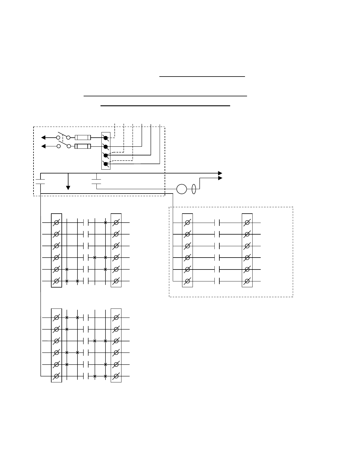
Appendix A - 10K12/18 Pendant and SLTX
Transmitter Programming (Continued)
A-20
TABLE 1(h)
Crane Control Type Selection: 10K12 2-Speed TYPE 6 WIRING DIAGRAM
____________________________________________________________________________________________________
DEMAG: 2-SPEED, 2-WINDINGS for HOIST:
STANDARD BRIDGE and TROLLEY
BJ3
1
2
3
4
5
6
BJ2
1
2
3
4
5
6
K1
K2
K3
K4
K5
K6
2 1 1 2
HOIST UP
HOIST UP
2
ND
SPD
HOIST DOWN
BRIDGE
NORTH
BRIDGE
2
ND
SPD
BRIDGE
SOUTH
•
•
•
•
•
*NOTE:
If it is necessary to operate the Alarm
Function during E-Stop condition, wire the input to the
alarm relay “J3” for the alarm function to the control
power hot side (relay “K1” (MR) on P/S Board de-
energized).
Telemotive receiver output boards
(E10165-X).
Multibox outputs available with factory
installed Multibox option only.
All connections to outputs AJ2, BJ2 and
CJ2 are to contactors, with proper arc
suppressors across them, controlling the
appropriate listed function to the right.
**Aux outputs 4 and 3 available with
Multibox. Aux outputs 3 to 6 available
with Multibox disabled. Aux 5 and 6
require a special transmitter see your
Telemotive representative.
240 VAC 120 VAC
SW1
ON/OFF
TO POWER
TRANSFORMER
E10171-X
P/S BOARD
MAIN LINE
CONTACTOR
TO
CONTROL
POWER
HOT
RET
(2)
K1 (MR)
(4)
•
•
•
*
See Note
•
240
120
FUSE J1
N
GND
(6)
K1 (MR)
(8)
•
•
•
AJ3
1
2
3
4
5
6
AJ2
1
2
3
4
5
6
2 1 1 2
HOIST DOWN
2
ND
SPD
AUX 2
AUX 1
TROLLEY
WEST
TROLLEY
2
ND
SPD
TROLLEY
EAST
•
•
•
•
•
•
CJ3
1
2
3
4
5
6
CJ2
1
2
3
4
5
6
K1
K2
K3
K4
K5
K6
OPTIONAL
**AUX 4
**AUX 3
MULTIBOX 1
**or AUX 5
MULTIBOX 2
**or AUX 6
MULTIBOX 3
MULTIBOX 4
•
•
•
•
•
K1
K2
K3
K4
K5
K6
MLC
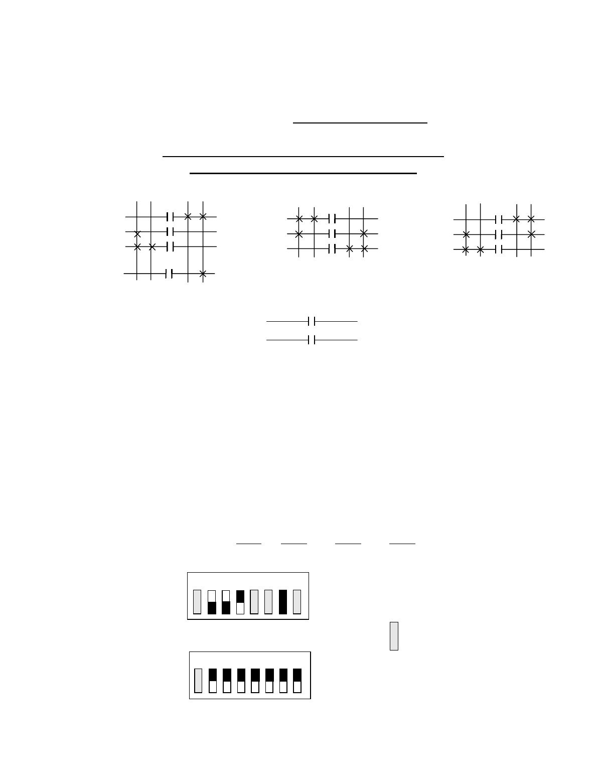
Appendix A - 10K12/18 Pendant and SLTX
Transmitter Programming (Continued)
A-21
TABLE 1(h)
Crane Control Type Selection: 10K12 2-Speed TYPE 6 PROGRAMMING
____________________________________________________________________________________________________
DEMAG: 2-SPEED, 2-WINDINGS for HOIST:
STANDARD BRIDGE and TROLLEY
STANDARD STANDARD OPTIONAL OUTPUT OPTIONAL OUTPUT
OUTPUTS OUTPUTS BOARD OPTION #1 BOARD OPTION #2
A1 HOIST DOWN 2ND SPEED B1 HOIST UP C1 AUX 4 C1 AUX 4
A2 AUX 2 (LATCHABLE S2-6) B2 HOIST UP 2ND SPEED C2 AUX 3 C2 AUX 3
A3 AUX 1 (LATCHABLE S2-7) B3 HOIST DOWN C3 MULTIBOX 1 C3 AUX 5
A4 TROLLEY WEST B4 BRIDGE NORTH C4 MULTIBOX 2 C4 AUX 6
A5 TROLLEY 2ND SPEED B5 BRIDGE 2ND SPEED C5 MULTIBOX 3 C5
A6 TROLLEY EAST B6 BRIDGE SOUTH C6 MULTIBOX 4 C6
Transmitter and Receiver Switch Select: Switch settings
Sw3-5 to Sw3-7 are defined as follows (for Optional Output
Board in the Receiver Sw3-3 must be “ON” for Option #1
and “OFF” for Option #2):
TRANSMITTER SWITCH SETTINGS: TYPE Sw4-7 Sw4-6 Sw4-5
6ON ON OFF
OUTPUTS
B3
B2
B1
A1
HOIST
OUTPUTS
A6
A5
A4
TROLLEY
OUTPUTS
B6
B5
B4
BRIDGE
1ST 2ND
1ST 2ND 1ST 2ND
UP DN E W N S
A3 AUX 1
INDEPENDENT OUTPUTS
A2 AUX 2
2ND 1ST
2ND 1ST 2ND 1ST
OFF
ON
Sw4
Sw3 OFF
ON
For these switch
positions see the
beginning of this
section.
18234567
18234567
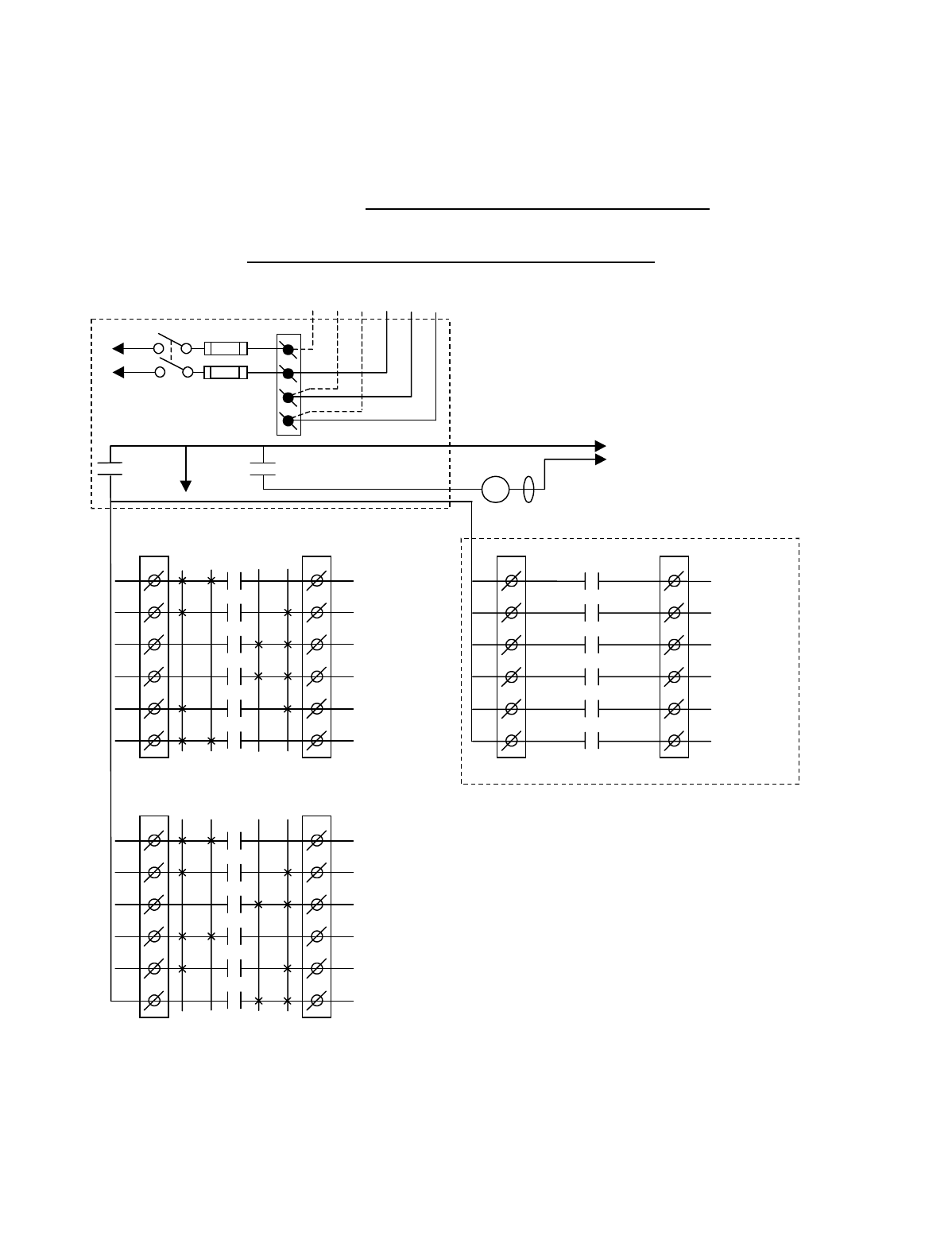
Appendix A - 10K12/18 Pendant and SLTX
Transmitter Programming (Continued)
A-22
TABLE 1(i)
Crane Control Type Selection: 10K12 CONFIGURATION 1 WIRING DIAGRAM
____________________________________________________________________________________________________
STANDARD 2-SPEED 4 MOTOR SYSTEM
BJ3
1
2
3
4
5
6
BJ2
1
2
3
4
5
6
K1
K2
K3
K4
K5
K6
2 1 1 2
HOIST
UP
HOIST
2
ND
SPD
HOIST
DOWN
BRIDGE
NORTH
BRIDGE
2
ND
SPD
BRIDGE
SOUTH
•
•
•
•
•
*NOTE:
If it is necessary to operate the Alarm
Function during E-Stop condition, wire the input to the
alarm relay “J3” for the alarm function to the control
power hot side (relay “K1” (MR) on P/S Board de-
energized).
Telemotive receiver output boards
(E10165-X).
Multibox outputs available with factory
installed Multibox option only.
All connections to outputs AJ2, BJ2 and
CJ2 are to contactors, with proper arc
suppressors across them, controlling the
appropriate listed function to the right.
**Aux outputs 4 and 3 available with
Multibox. Aux outputs 1 to 6 available
with Multibox disabled. Aux 5 and 6
require a special transmitter see your
Telemotive representative
240 VAC 120 VAC
SW1
ON/OFF
TO POWER
TRANSFORMER
E10171-X
P/S BOARD
MAIN LINE
CONTACTOR
TO
CONTROL
POWER
HOT
RET
(2)
K1 (MR)
(4)
•
•
•
*
See Note
•
240
120
FUSE J1
N
GND
(6)
K1 (MR)
(8)
•
•
•
AJ3
1
2
3
4
5
6
AJ2
1
2
3
4
5
6
2 1 1 2
AUX HOIST
UP
AUX HOIST
2
ND
SPD
AUX HOIST
DOWN
TROLLEY
WEST
TROLLEY
2
ND
SPD
TROLLEY
EAST
•
•
•
•
•
•
CJ3
1
2
3
4
5
6
CJ2
1
2
3
4
5
6
K1
K2
K3
K4
K5
K6
OPTIONAL
**AUX 4
**AUX 3
MULTIBOX 1
**or AUX 2
MULTIBOX 2
**or AUX 1
MULTIBOX 3
**or AUX 5
MULTIBOX 4
**or AUX 6
•
•
•
•
•
K1
K2
K3
K4
K5
K6
MLC
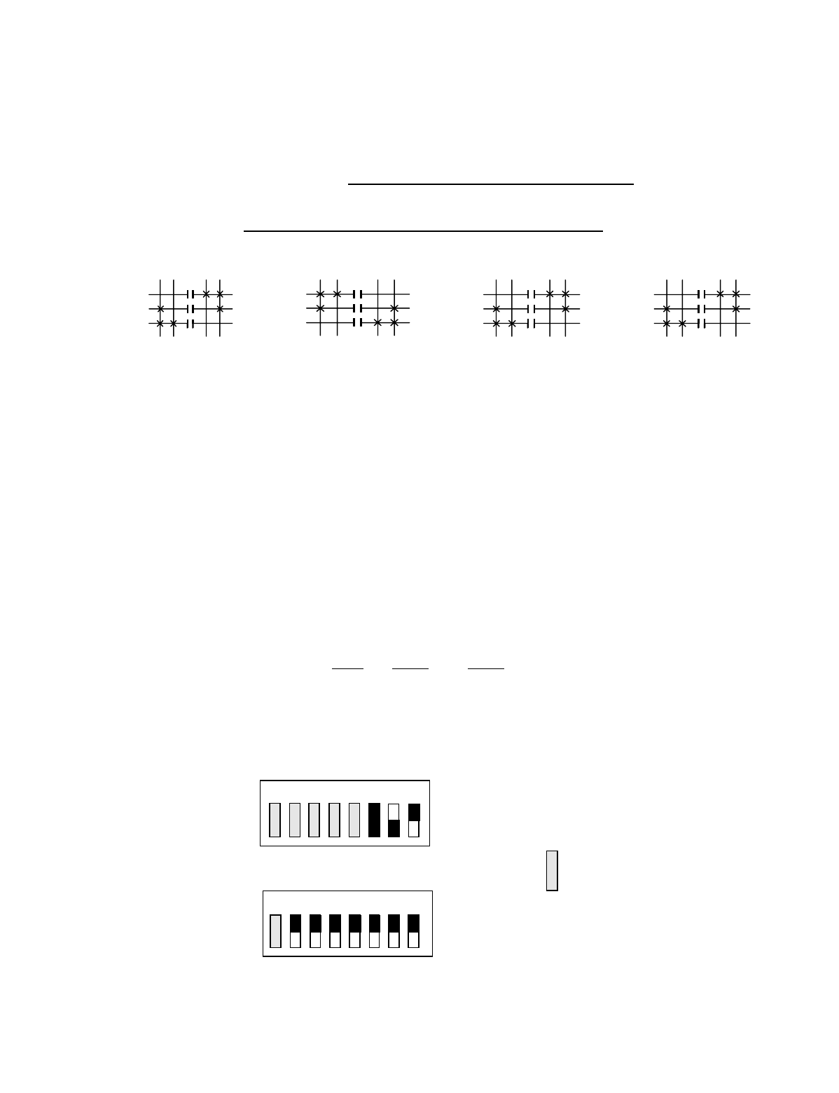
Appendix A - 10K12/18 Pendant and SLTX
Transmitter Programming (Continued)
A-23
TABLE 1(i)
Crane Control Type Selection: 10K12 CONFIGURATION 1 PROGRAMMING
____________________________________________________________________________________________________
STANDARD 2-SPEED 4 MOTOR SYSTEM
STANDARD STANDARD OPTIONAL OUTPUT OPTIONAL OUTPUT
OUTPUTS OUTPUTS BOARD OPTION #1 BOARD OPTION #2
A1 AUX HOIST UP B1 HOIST UP C1 AUX 4 C1 AUX 4
A2 AUX HOIST 2ND SPEED B2 HOIST 2ND SPEED C2 AUX 3 C2 AUX 3
A3 AUX HOIST DOWN B3 HOIST DOWN C3 MULTIBOX 1 C3 AUX 2
A4 TROLLEY WEST B4 BRIDGE NORTH C4 MULTIBOX 2 C4 AUX 1
A5 TROLLEY 2ND SPEED B5 BRIDGE 2ND SPEED C5 MULTIBOX 3 C5 AUX 5
A6 TROLLEY EAST B6 BRIDGE SOUTH C6 MULTIBOX 4 C6 AUX 6
Transmitter and Receiver Switch Select: Switch settings
Sw3-5 to Sw3-7 are defined as follows (for Optional Output
Board in the Receiver Sw3-3 must be “ON” for Option #1
and “OFF” for Option #2):
TRANSMITTER SWITCH SETTINGS: Conf. Sw4-2 Sw4-1
1ON OFF
OUTPUTS
A3
A2
A1
AUX HOIST
OUTPUTS
A6
A5
A4
TROLLEY
OUTPUTS
B6
B5
B4
BRIDGE
2
ND
1
ST
1
ST
2
ND
UP DN E W N S UP DN
OUTPUTS
B3
B2
B1
HOIST
2
ND
1
ST
1
ST
2
ND
2
ND
1
ST
1
ST
2
ND
2
ND
1
ST
1
ST
2
ND
OFF
ON
Sw4
Sw3 OFF
ON
For these switch
positions see the
beginning of this
section.
18234567
18234567
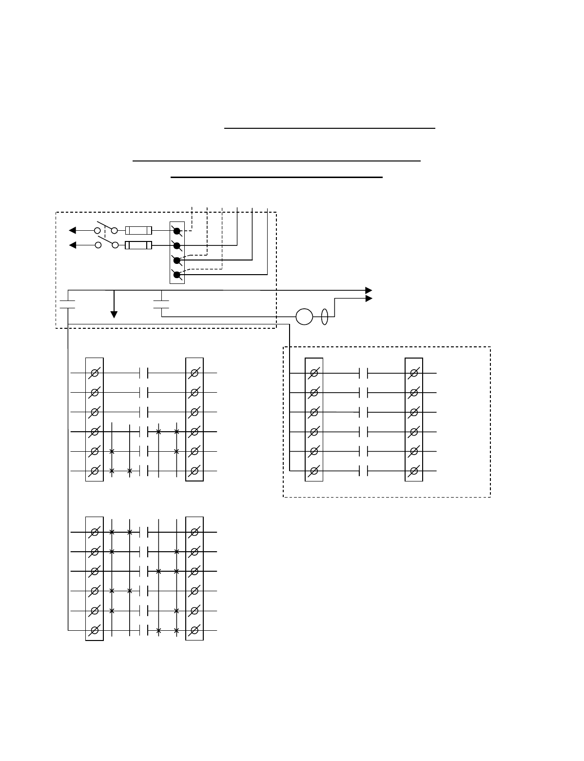
Appendix A - 10K12/18 Pendant and SLTX
Transmitter Programming (Continued)
A-24
TABLE 1(j)
Crane Control Type Selection: 10K12 CONFIGURATION 2 WIRING DIAGRAM
____________________________________________________________________________________________________
STANDARD 2-SPEED 3, 4 & 5 MOTOR SYSTEM
(EXTERNAL SELECT VERSION A)
BJ3
1
2
3
4
5
6
BJ2
1
2
3
4
5
6
K1
K2
K3
K4
K5
K6
2 1 1 2
HOIST
UP
HOIST
2
ND
SPD
HOIST
DOWN
BRIDGE
NORTH
BRIDGE
2
ND
SPD
BRIDGE
SOUTH
•
•
•
•
•
*NOTE 1:
If it is necessary to operate the Alarm
Function during E-Stop condition, wire the input to the
alarm relay “J3” for the alarm function to the control
power hot side (relay “K1” (MR) on P/S Board de-
energized).
Telemotive receiver output boards (E10165-X).
Note 2: The select function can be inverted by turning
Receiver CPU switch S4 position 4 to “ON”. See the details
at the beginning of this section.
Multibox outputs available with factory installed Multibox
option only.
All connections to outputs AJ2, BJ2 and CJ2 are to
contactors, with proper arc suppressors across them,
controlling the appropriate listed function to the right.
**Aux outputs 1 and 2 available with Multibox. Aux
outputs 1, 2 and 4 to 6 available with Multibox disabled.
Aux 5 and 6 require a special transmitter see your
Telemotive representative.
240 VAC 120 VAC
SW1
ON/OFF
TO POWER
TRANSFORMER
E10171-X
P/S BOARD
MAIN LINE
CONTACTOR
TO
CONTROL
POWER
HOT
RET
(2)
K1 (MR)
(4)
•
•
•
*
See Note 1
•
240
120
FUSE J1
N
GND
(6)
K1 (MR)
(8)
•
•
•
AJ3
1
2
3
4
5
6
AJ2
1
2
3
4
5
6
2 1 1 2
AUX 3
SELECT 1
See Note 2:
SELECT 2
See Note 2:
TROLLEY
WEST
TROLLEY
2
ND
SPD
TROLLEY
EAST
•
•
•
•
•
•
CJ3
1
2
3
4
5
6
CJ2
1
2
3
4
5
6
K1
K2
K3
K4
K5
K6
OPTIONAL
**AUX 1
**AUX 2
MULTIBOX 1
**or AUX 4
MULTIBOX 2
**or Aux 5
MULTIBOX 3
**or Aux 6
MULTIBOX 4
•
•
•
•
•
K1
K2
K3
K4
K5
K6
MLC
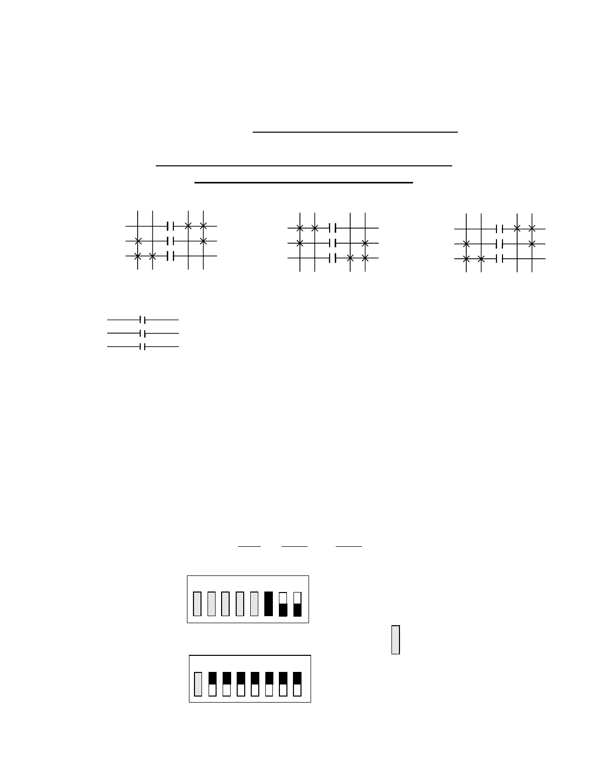
Appendix A - 10K12/18 Pendant and SLTX
Transmitter Programming (Continued)
A-25
TABLE 1(j)
Crane Control Type Selection: 10K12 CONFIGURATION 2 PROGRAMMING
____________________________________________________________________________________________________
STANDARD 2-SPEED 3, 4 & 5 MOTOR SYSTEM
(EXTERNAL SELECT VERSION A)
STANDARD STANDARD OPTIONAL OUTPUT OPTIONAL OUTPUT
OUTPUTS OUTPUTS BOARD OPTION #1 BOARD OPTION #2
A1 AUX 3 (ALARM) B1 HOIST UP C1 AUX 1 C1 AUX 1
A2 SELECT 1 B2 HOIST 2ND SPEED C2 AUX 2 C2 AUX 2
A3 SELECT 2 B3 HOIST DOWN C3 MULTIBOX 1 C3 AUX 4
A4 TROLLEY WEST B4 BRIDGE NORTH C4 MULTIBOX 2 C4 AUX 5
A5 TROLLEY 2ND SPEED B5 BRIDGE 2ND SPEED C5 MULTIBOX 3 C5 AUX 6
A6 TROLLEY EAST B6 BRIDGE SOUTH C6 MULTIBOX 4 C6
Transmitter and Receiver Switch Select: Switch settings
Sw3-5 to Sw3-7 are defined as follows (for Optional Output
Board in the Receiver Sw3-3 must be “ON” for Option #1
and “OFF” for Option #2):
TRANSMITTER SWITCH SETTINGS: Conf. Sw4-2 Sw4-1
2ON ON
OUTPUTS
B3
B2
B1
HOIST
OUTPUTS
A6
A5
A4
TROLLEY
OUTPUTS
B6
B5
B4
BRIDGE
A3
A2
A1
SELECT 1
SELECT 2
AUX 3 ALARM
2ND 1ST 1ST 2ND 1ST 2ND 1ST 2ND
UP DN E W N S
INDEPENDENT OUTPUTS
2ND 1ST 2ND 1ST
OFF
ON
Sw4
Sw3 OFF
ON
For these switch
positions see the
beginning of this
section.
18234567
18234567
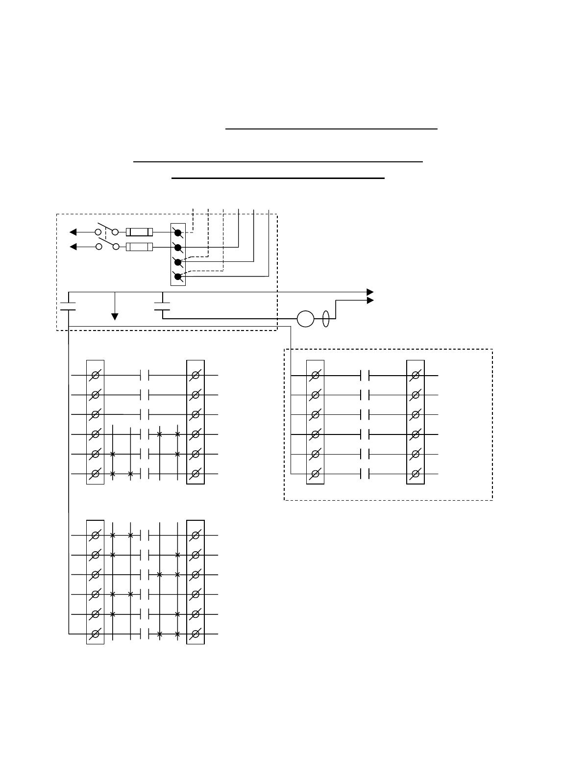
Appendix A - 10K12/18 Pendant and SLTX
Transmitter Programming (Continued)
A-26
TABLE 1(k)
Crane Control Type Selection: 10K12 CONFIGURATION 3 WIRING DIAGRAM
____________________________________________________________________________________________________
STANDARD 2-SPEED 3, 4 & 5 MOTOR SYSTEM
(EXTERNAL SELECT VERSION B)
BJ3
1
2
3
4
5
6
BJ2
1
2
3
4
5
6
K1
K2
K3
K4
K5
K6
2 1 1 2
HOIST
UP
HOIST
2
ND
SPD
HOIST
DOWN
BRIDGE
NORTH
BRIDGE
2
ND
SPD
BRIDGE
SOUTH
•
•
•
•
•
*NOTE 1:
If it is necessary to operate the Alarm
Function during E-Stop condition, wire the input to the
alarm relay “J3” for the alarm function to the control
power hot side (relay “K1” (MR) on P/S Board de-
energized).
Telemotive receiver output boards (E10165-X).
Note 2: The select function can be inverted by turning
Receiver CPU switch S4 position 4 to “ON”. See the
details at the beginning of this section.
Multibox outputs available with factory installed
Multibox option only.
All connections to outputs AJ2, BJ2 and CJ2 are to
contactors, with proper arc suppressors across them,
controlling the appropriate listed function to the right.
** Aux outputs 4 to 6 available with Multibox disabled.
Aux 5 and 6 require a special transmitter see your
Telemotive representative.
240 VAC 120 VAC
SW1
ON/OFF
TO POWER
TRANSFORMER
E10171-X
P/S BOARD
MAIN LINE
CONTACTOR
TO
CONTROL
POWER
HOT
RET
(2)
K1 (MR)
(4)
•
•
•
*
See Note 1
•
240
120
FUSE J1
N
GND
(6)
K1 (MR)
(8)
•
•
•
AJ3
1
2
3
4
5
6
AJ2
1
2
3
4
5
6
2 1 1 2
AUX 3
AUX 2
AUX 1
TROLLEY
WEST
TROLLEY
2
ND
SPD
TROLLEY
EAST
•
•
•
•
•
•
CJ3
1
2
3
4
5
6
CJ2
1
2
3
4
5
6
K1
K2
K3
K4
K5
K6
OPTIONAL
SELECT 2
See Note 2
SELECT 1
See Note 2
MULTIBOX 1
**or AUX 4
MULTIBOX 2
**or AUX 5
MULTIBOX 3
**or AUX 6
MULTIBOX 4
•
•
•
•
•
K1
K2
K3
K4
K5
K6
MLC
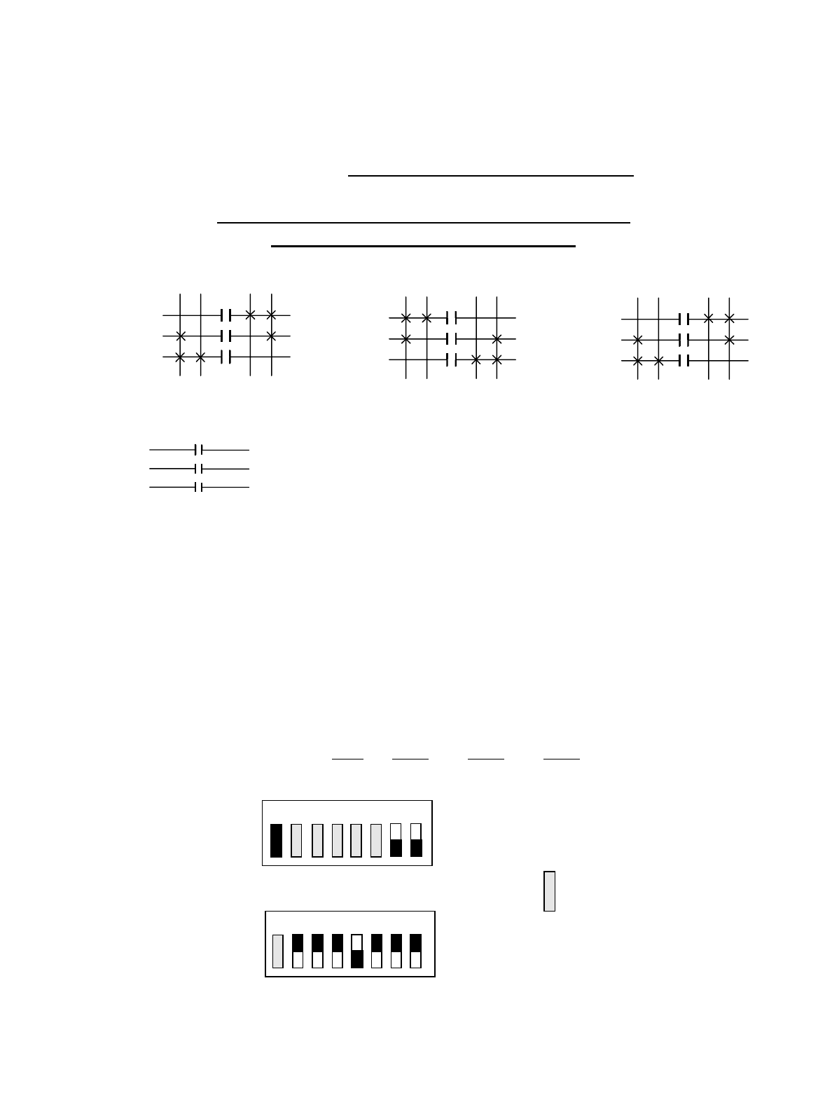
Appendix A - 10K12/18 Pendant and SLTX
Transmitter Programming (Continued)
A-27
TABLE 1(k)
Crane Control Type Selection: 10K12 CONFIGURATION 3 PROGRAMMING
____________________________________________________________________________________________________
STANDARD 2-SPEED 3, 4 & 5 MOTOR SYSTEM
(EXTERNAL SELECT VERSION B)
STANDARD STANDARD OPTIONAL OUTPUT OPTIONAL OUTPUT
OUTPUTS OUTPUTS BOARD OPTION #1 BOARD OPTION #2
A1 AUX 3 (ALARM) B1 HOIST UP C1 SELECT 2 C1 SELECT 2
A2 AUX 2 (LATCHABLE S2-6) B2 HOIST 2ND SPEED C2 SELECT 1 C2 SELECT 1
A3 AUX 1 (LATCHABLE S2-7) B3 HOIST DOWN C3 MULTIBOX 1 C3 AUX 4
A4 TROLLEY WEST B4 BRIDGE NORTH C4 MULTIBOX 2 C4 AUX 5
A5 TROLLEY 2ND SPEED B5 BRIDGE 2ND SPEED C5 MULTIBOX 3 C5 AUX 6
A6 TROLLEY EAST B6 BRIDGE SOUTH C6 MULTIBOX 4 C6
Transmitter and Receiver Switch Select: Switch settings
Sw3-5 to Sw3-7 are defined as follows (for Optional Output
Board in the Receiver Sw3-3 must be “ON” for Option #1
and “OFF” for Option #2):
TRANSMITTER SWITCH SETTINGS: Conf. Sw4-2 Sw4-1 Sw3-4
3ONONON
OUTPUTS
B3
B2
B1
HOIST
OUTPUTS
A6
A5
A4
TROLLEY
OUTPUTS
B6
B5
B4
BRIDGE
A3
A2
A1
AUX 1
AUX 2
AUX 3 ALARM
2ND 1ST 1ST 2ND 1ST 2ND 1ST 2ND
UP DN E W N S
INDEPENDENT OUTPUTS
2ND 1ST 2ND 1ST
OFF
ON
Sw4
Sw3 OFF
ON
For these switch
positions see the
beginning of this
section.
18234567
18234567
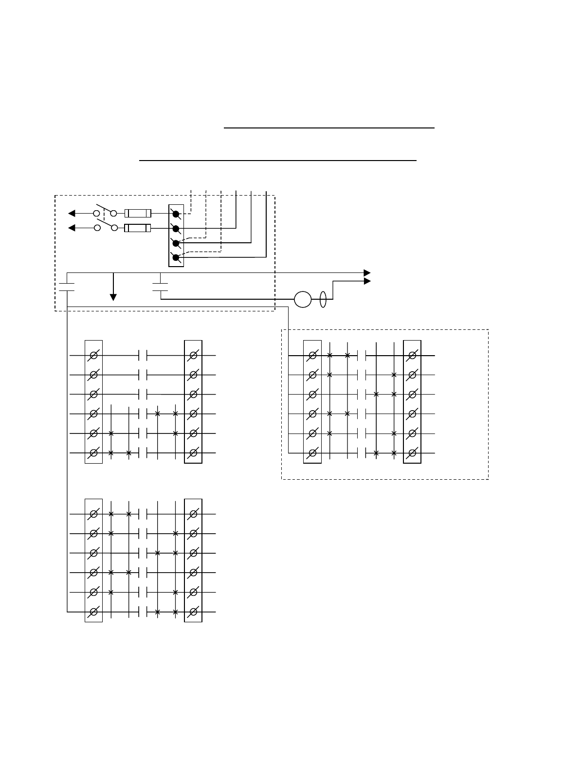
Appendix A - 10K12/18 Pendant and SLTX
Transmitter Programming (Continued)
A-28
TABLE 1(l)
Crane Control Type Selection: 10K12 CONFIGURATION 4 WIRING DIAGRAM
____________________________________________________________________________________________________
STANDARD 2-SPEED 4 & 5 MOTOR SYSTEM
BJ3
1
2
3
4
5
6
BJ2
1
2
3
4
5
6
K1
K2
K3
K4
K5
K6
2 1 1 2
HOIST
UP
HOIST
2
ND
SPD
HOIST
DOWN
BRIDGE
NORTH
BRIDGE
2
ND
SPD
BRIDGE
SOUTH
•
•
•
•
•
*NOTE:
If it is necessary to operate the Alarm
Function during E-Stop condition, wire the input to the
alarm relay “J3” for the alarm function to the control
power hot side (relay “K1” (MR) on P/S Board de-
energized).
Multibox outputs available with factory
installed Multibox option only.
All connections to outputs AJ2, BJ2 and
CJ2 are to contactors, with proper arc
suppressors across them, controlling the
appropriate listed function to the right.
Telemotive receiver output boards
(E10165-X).
240 VAC 120 VAC
SW1
ON/OFF
E10171-X
P/S BOARD
MAIN LINE
CONTACTOR
TO
CONTROL
POWER
HOT
RET
(2)
K1 (MR)
(4)
•
•
•
*
See Note
•
240
120
FUSE J1
N
GND
(6)
K1 (MR)
(8)
•
•
•
AJ3
1
2
3
4
5
6
AJ2
1
2
3
4
5
6
2 1 1 2
AUX 3
AUX 2
AUX 1
TROLLEY
WEST
TROLLEY
2
ND
SPD
TROLLEY
EAST
•
•
•
•
•
•
CJ3
1
2
3
4
5
6
CJ2
1
2
3
4
5
6
K1
K2
K3
K4
K5
K6
OPTIONAL
AUX HOIST
DOWN
AUX HOIST
2
ND
SPD
AUX HOIST
UP
AUX TROLLEY
EAST
AUX TROLLEY
2
ND
SPD
AUX TROLLEY
WEST
•
•
•
•
•
K1
K2
K3
K4
K5
K6
2 1 1 2
MLC
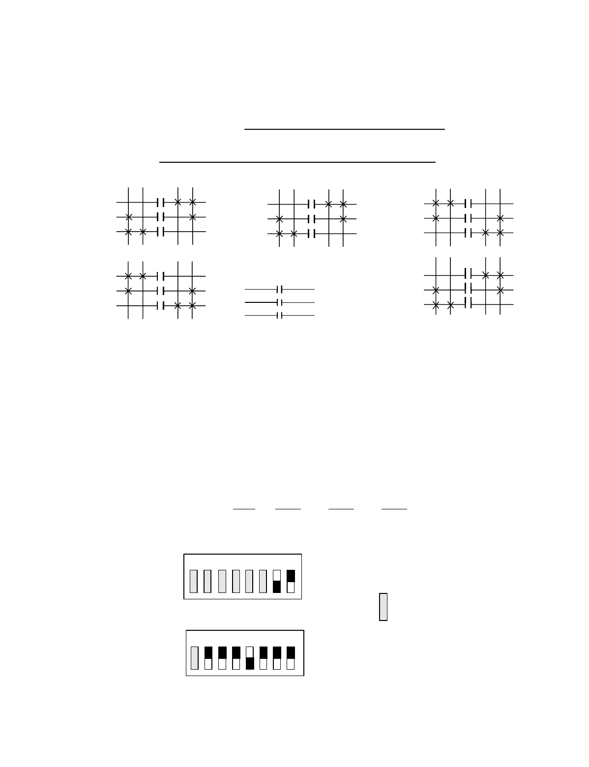
Appendix A - 10K12/18 Pendant and SLTX
Transmitter Programming (Continued)
A-29
TABLE 1(l)
Crane Control Type Selection: 10K12 CONFIGURATION 4 PROGRAMMING
____________________________________________________________________________________________________
STANDARD 2-SPEED 4 & 5 MOTOR SYSTEM
STANDARD STANDARD OPTIONAL OUTPUT
OUTPUTS OUTPUTS BOARD OPTION #1
A1 AUX 3 (ALARM) B1 HOIST UP C1 AUX HOIST DOWN
A2 AUX 2 (LATCHABLE S2-6) B2 HOIST 2ND SPEED C2 AUX HOIST 2ND SPEED
A3 AUX 1 (LATCHABLE S2-7) B3 HOIST DOWN C3 AUX HOIST UP
A4 TROLLEY WEST B4 BRIDGE NORTH C4 AUX TROLLEY EAST
A5 TROLLEY 2ND SPEED B5 BRIDGE 2ND SPEED C5 AUX TROLLEY 2ND SPEED
A6 TROLLEY EAST B6 BRIDGE SOUTH C6 AUX TROLLEY WEST
Transmitter and Receiver Switch Select: Switch settings
Sw3-5 to Sw3-7 are defined as follows (for Optional Output
Board in the Receiver Sw3-3 must be “ON” for Option #1):
TRANSMITTER SWITCH SETTINGS: Conf. Sw4-2 Sw4-1 Sw3-4
4ON OFF ON
OUTPUTS
B3
B2
B1
HOIST
OUTPUTS
B6
B5
B4
BRIDGE
2ND 1ST 1ST 2ND 1ST 2ND
UP DN N S
A3
A2
A1
AUX 1
AUX 2
AUX 3
ALARM
INDEPENDENT OUTPUTS
2ND 1ST
OUTPUTS
A6
A5
A4
TROLLEY 1ST 2ND
E W
2ND 1ST
1ST 2ND 1ST 2ND
2ND 1ST
OUTPUTS
C6
C5
C4
AUX
TROLLEY 2ND 1ST
OUTPUTS
C3
C2
C1
AUX
HOIST
OFF
ON
Sw4
Sw3 OFF
ON
For these switch
positions see the
beginning of this
section.
18234567
18234567
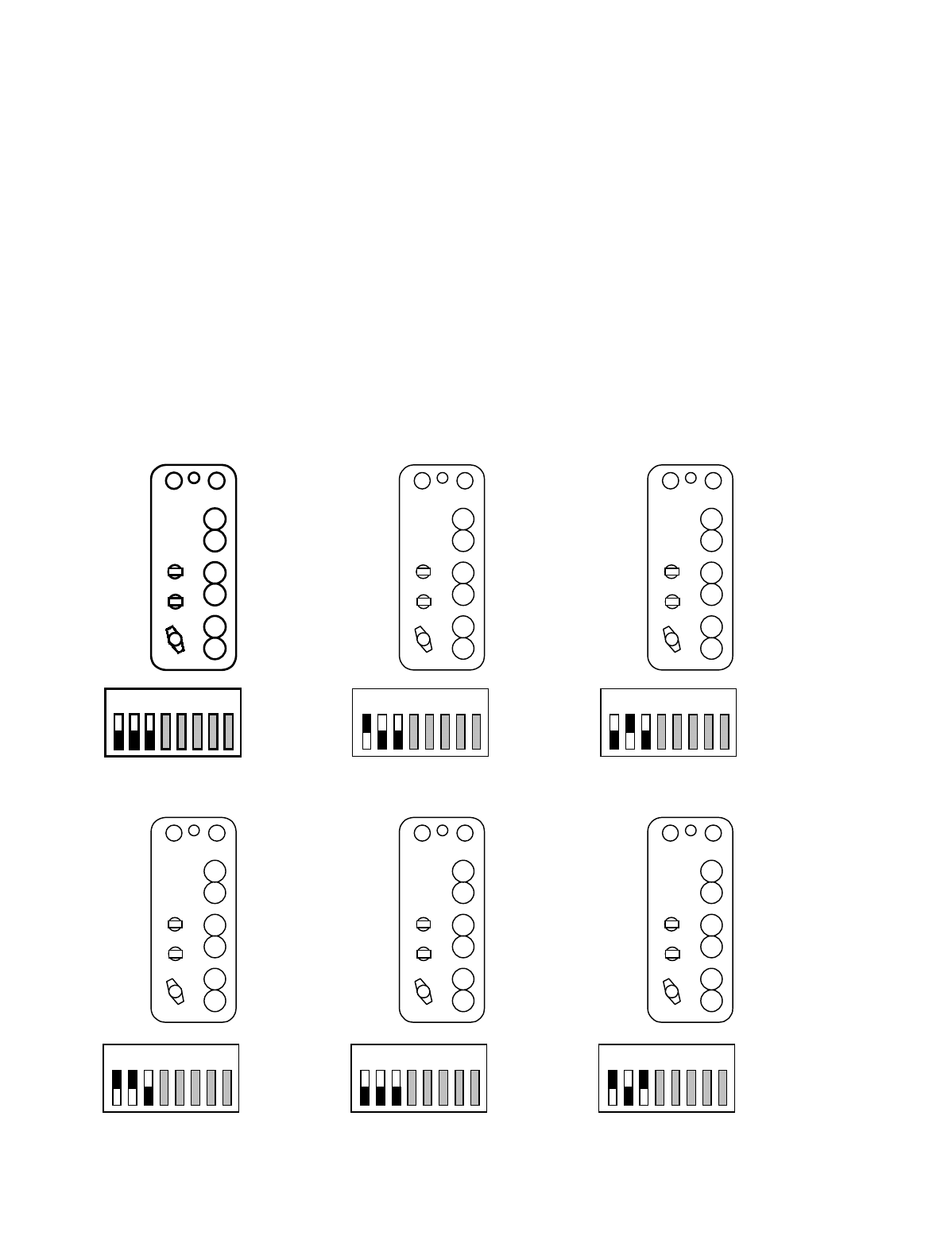
Appendix A - 10K12/18 Pendant and SLTX
Transmitter Programming (Continued)
A-30
TABLE 1(m)
Repositioning of transmitter pushbutton switch functions for pendant only.
____________________________________________________________________________________________________
SW3 positions 1 through 3 can change the functional positions of the switches controlling trolley, hoist and bridge. This can
be usefull to align EAST/WEST and NORTH/SOUTH. This reconfiguration does NOT affect receiver wiring.
____________________________________________________________________________________________________
WARNING
CHANGING THESE SWITCHES CHANGES THE FUNCTIONAL OPERATION OF THE CRANE IN RELATIONSHIP
TO THE TRANSMITTER BUTTON BEING DEPRESSED. THE FUNCTIONAL OPERATION OF THE CRANE
SHOULD NEVER BE CHANGED WITHOUT ALL PERSONNEL RESPONSIBLE FOR CRANE OPERATION BEING
NOTIFIED PRIOR TO MODIFICATION.
12345678ON
OFF
HOIST
TROLLEY
BRIDGE
HOIST
BRIDGE
TROLLEY
BRIDGE
TROLLEY
HOIST
BRIDGE
HOIST
TROLLEY
TROLLEY
HOIST
BRIDGE
TROLLEY
BRIDGE
HOIST
Standard Configuration
12345678ON
OFF
12345678ON
OFF
12345678ON
OFF
12345678ON
OFF
12345678ON
OFF

B-1
NOTE: This section also contains information on Optional Output Board for Multibox and other
optional outputs.
Appendix B - 10K12 2-Speed Membrane Transmitter
Programming

Appendix B - 10K12 2-Speed Membrane Transmitter
Programming (Continued)
B-2
B-1. Transmitter Switches Sw3 and Sw4
Programming. (See Section 6-3 for physical
location of transmitter switches).
B-1.1. Transmitter programming Sw3
B-1.1.1. Positions 1-3 Switch Positioning.
(Standard configuration all “OFF”).
NOTE
Transmitter Sw4 positions 1-2 must be set to “OFF” (2-
speed) for Switch Positioning to function.
For the 2-speed membrane transmitter the functional posi-
tions of the various buttons controlling the hoist , bridge and
trolley can be moved by transmitter dip switch Sw3 also.
Positions Sw3-1 through Sw3-3 control these functions. No
change in receiver wiring is needed to use these functions.
See TABLE 1(i) for switch verses button configurations.
B-1.1.2. Position 4 Time-out-timer Disable.
(Normally keep turned “OFF”).
The transmitter has an approximate 15-minute time-out-
timer. If the transmitter is not used for over 15 minutes it
will shut down. This transmitter time-out-timer function is
transmitter dip switch selectable. Sw4 position 4 disables
the time-out-timer. Turning Sw4-4 “ON” disables the time-
out-timer. See TABLE 1(h) for details.
B-1.1.3. Positions 5-7 Extended Crane Control
Configurations. (Standard all “OFF”
otherwise see TABLE 1(b) through TABLE
1(g)).
Extended Crane Control Options for 10K12 2-Speed Mem-
brane Transmitter:
The 10K12 2-Speed Membrane transmitter is available with
extended crane control configurations. These options are
switch configurable on the transmitter microcomputer mod-
ule. The eight-position dip switch Sw3 can provide all con-
figurations with a single transmitter CPU EPROM. Table 1
shows the available configurations and the transmitter
switch programming needed to provide them. The standard
2-speed transmitter comes with the output configuration as
shown in TABLE 1(a): TYPE 0 and has no extended crane
control configurations. Its wiring is shown in TABLE 1(a):
TYPE 0. For extended crane control configurations:
See TABLE 1(b) through TABLE 1(g): TYPE 1 through
TYPE 6 respectively. If a configuration listed in TABLE
1(b) through TABLE 1(g) is preferred over the standard
configuration, please reprogram transmitter switch Sw3.
B-1.1.4. Position 8 no function. (Keep turned
“OFF”).
B-1.2. Transmitter programming Sw4
B-1.2.1. Positions 1-2 Mode Enable. (See
Membrane Transmitter Mode Select page 6-5).
(All 2-speed configurations all “OFF”).
Mode 0, Sw4 1 turned “OFF” and Sw4 2 turned “OFF”.
From the factory the standard membrane transmitter is the
2-speed configured this way. This mode in the membrane
transmitter is for all 2-speed applications. If the membrane
transmitter has a 2-speed keypad Sw4 must be set to all
“OFF” positions.
(The following three single speed modes are listed for
replacement purposes only.) Mode 1, Sw4 1 turned “ON”
and Sw4 2 turned “OFF”. This configuration gives four
motor single speed with four auxiliaries. This configuration
uses the single speed keypad with two auxiliaries labeled P1
and P2.
Mode 2, Sw4 1 turned “OFF” and Sw4 2 turned “ON”. This
configuration gives four motor single speed with four auxil-
iaries. This configuration uses the single speed keypad with
four auxiliaries labeled Aux 1 through Aux 4.
Mode 3, Sw4 1 turned “ON” and Sw4 2 turned “ON”.
Allows for 12 independent on/off functions (relays) per
transmitter button pushed.
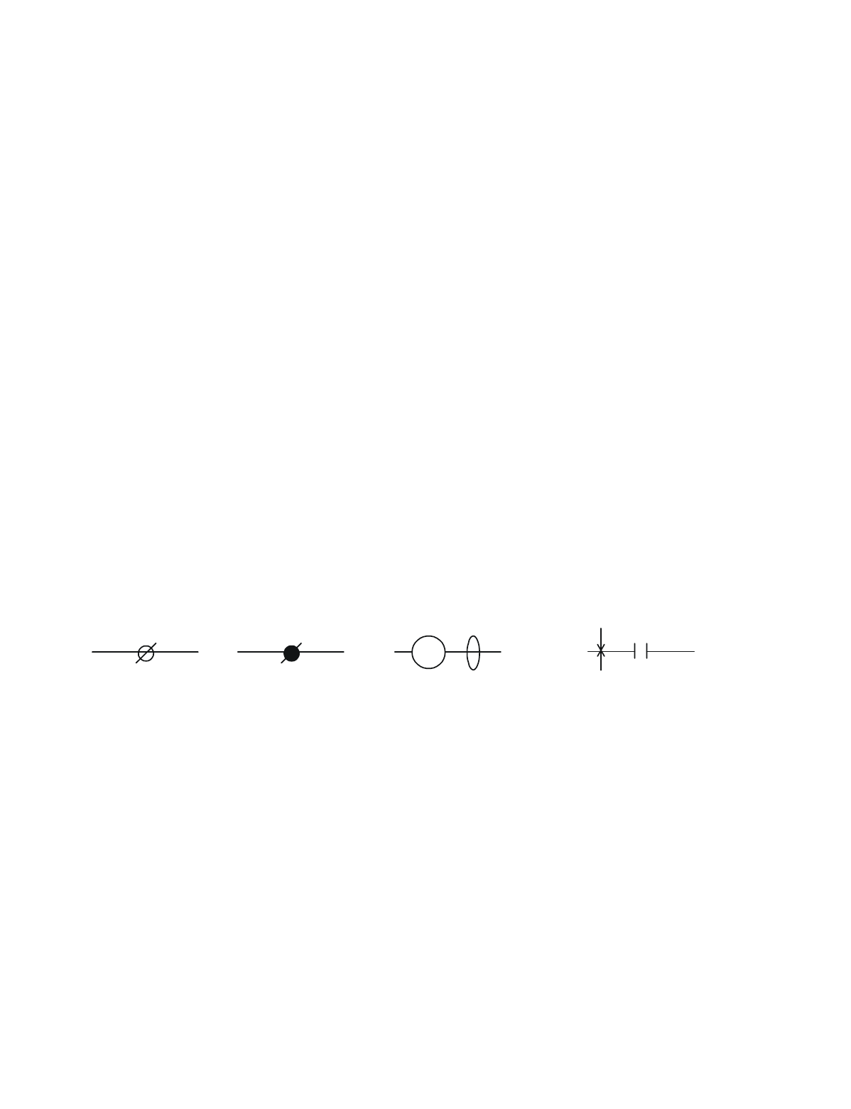
Appendix B - 10K12 2-Speed Membrane Transmitter
Programming (Continued)
B-3
B-2. Replacement Transmitter EPROM’s
All 2-speed membrane transmitters with M/C Module
E10678-X use CPU EPROM part number FW2836-0.
B-3. Multibox and Optional Output Board:
WARNING
IF YOUR UNIT WAS NOT ORDERED WITH MULTI-
BOX DO NOT ATTEMPT TO PROGRAM MULTIBOX
IN THE FIELD. TELEMOTIVE MUST COORDINATE
ACCESS CODE ASSIGNMENTS WITH THE TRANS-
MITTERS PRIOR TO ENABLING MULTIBOX.
PLEASE CONTACT TELEMOTIVE IF YOU NEED TO
ADD MULTIBOX. FAILURE TO DO SO CAN BE A
SERIOUS SAFETY HAZARD.
If Multibox is used (Receiver switch Sw3-3 is “ON” and the
Optional Output Board is installed in the receiver). The out-
puts are as follows:
C1-C2 Defined per type
C3 MULTIBOX 1
C4 MULTIBOX 2
C5 MULTIBOX 3
C6 MULTIBOX 4
B-4. Latching of Auxiliary Relays
Certain auxiliary relays can be set to latch (be toggled on
and off) by setting dip switch S2 positions 6-8 on the
Receiver CPU Board. If an Aux function is latchable it is
noted in the programming diagram by the following note
(LATCHABLE S2-#) where # is the switch position 6-8 that
must be turned on for the latching function.
B-5. TABLE 1(a) through TABLE 1(g) Wiring
and Programming Diagrams
The following tables give various extended crane configura-
tions. Functional terms like Trolley South and Hoist Up
match standard transmitter labeling from the factory. The
following legend is used in these diagrams:
#
Indicates terminal
block J2 or J3 with
terminal number #
in the radio receiver
output board
GND
Indicates terminal
block J1 in power
supply board with
the required con-
nection noted.
Indicates customer
supplied contactor coil
with arc suppressor in
parallel.
MLC
Indicates a relay contact in radio
receiver number #. The X
indicates the relay closing and the
closing sequence (1
st
, 2
nd
, etc.) as
the indicated switch is de
p
ressed.
K#
1
ST
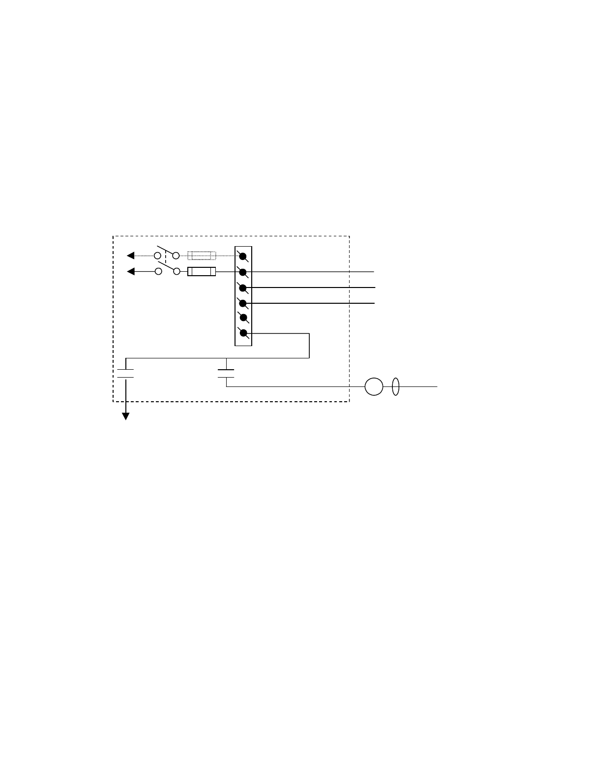
Appendix B - 10K12 2-Speed Membrane Transmitter
Programming (Continued)
B-4
In the following wiring diagrams the relay outputs AJ2, BJ2
and CJ2 have listed to the right of the output terminal the
appropriate motor function they control, i.e., trolley, hoist
etc. Proper installation requires that this output be wired to
a contactor controlling that function and that the contactor
has the proper arc suppressor across it. The relays on these
output boards are rated at 16 amps and fused at 10 amps
unless otherwise noted.
B-6. Optional 110 Volt Wiring
Power supply wiring is accomplished through connector J1
on the power supply board. The connections labeled 240,
120, N and GND are wired to the appropriate supply con-
nections per the wiring diagrams. An extra connection 120
is provided for 120 Volt applications only for jumpering to
Pins 2 and 6 of the Master Relay (MR) K1 on the power
supply board. The unit may optionally be wired as in Figure
B-1. Figure B-2 shows the wiring layout. All other wiring
is accomplished per the attached tables.
Figure B-1. Optional 120 VAC Wiring Diagram
SW1
ON/OFF
E10171-X
P/S BOARD
(2)
K1 (M R)
(4)
•
•
120
FUSE J1
N
GND
N
120
(6)
K1 (M R)
(8)
•
•
•
120 VAC
MLC
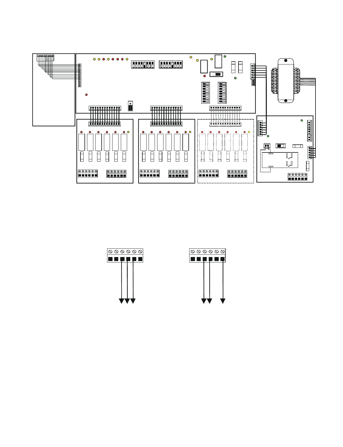
Appendix B - 10K12 2-Speed Membrane Transmitter
Programming (Continued)
B-5
Figure B-2. 10K12 Wiring Layout
B-7. Crane Control Type Selection
The crane control type selection information is provided in
TABLE 1(a) through TABLE 1(i). Each table defines a spe-
cific configuration and provides a wiring diagram, a pro-
gramming diagram, and transmitter and receiver switch
settings. The table for each configuration is provided on
facing pages so that all information is easily accessible.
J1 Power Supply
Board
NGNDN120 240120
Ground
Neutral
120VAC
NGNDN120 240120
Ground
240VAC B
240VAC A
220 VAC Wirin
g
110 VAC Wirin
g
J5
F2
DS2
DS
1SW1
ON OFF
J2
J3 J7
POWER
SUPPLY
BOARD
DS1
K1
F1
J2
1 2 3 4 5 6 1 2 3 4 5 6
J3
F2 F3 F4 F5 F6
K2 K3 K4 K5 K6
DS2 DS3 DS4 DS5 DS6
DS
7
J1
RELAY BOARD
RECEIVER BOARD
DS1
K1
F1
J2
1 2 3 4 5 6 1 2 3 4 5 6
J3
F2 F3 F4 F5 F6
K2 K3 K4 K5 K6
DS2 DS3 DS4 DS5 DS6
DS
7
J1
RELAY BOARD
T
R
A
N
S
F
O
R
M
E
R
J3
J4
DS-15
DS2
K
1
S1
DS5
DS4 DS1
DS3
J7 J8 J6
87654321
87654 321
0FF 0FF
S3 S2
0FF
87 654 321
S5
87654321
S4
0FF
DS-7 -8 -9 -10 -11-12 -13-14
J5
JU2
J2
J1
K
2
DS6
ON
CPU BOARD
F1
J6
J1
NGNDN120 240120
2
86
4
MASTER
CONTROL
RELAY
(MCR)
K1
OUTPUTS INPUTS OUTPUTS INPUTS OUTPUTS INPUTS
Position A Position B Position C
BA
F2 F1
DS1
K1
F1
J2
1 2 3 4 5 6 1 2 3 4 5 6
J3
F2 F3 F4 F5 F6
K2 K3 K4 K5 K6
DS2 DS3 DS4 DS5 DS6
DS
7
J1
RELAY BOARD
OPTIONAL OUTPUT BOARD
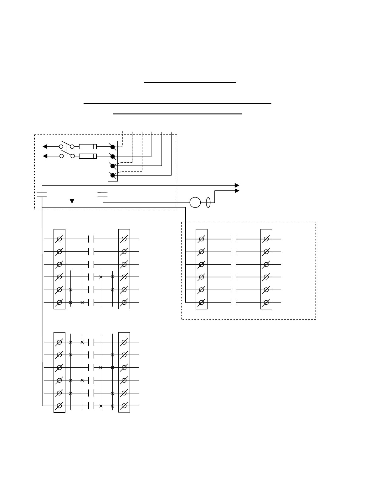
Appendix B - 10K12 2-Speed Membrane Transmitter
Programming (Continued)
B-6
TABLE 1(a)
Crane Control Type Selection: 10K12 TYPE 0 WIRING DIAGRAM
____________________________________________________________________________________________________
STANDARD CONFIGURATION: ALL MOTIONS
(HOIST, TROLLEY and BRIDGE )
BJ3
1
2
3
4
5
6
BJ2
1
2
3
4
5
6
K1
K2
K3
K4
K5
K6
2 1 1 2
HOIST
UP
HOIST
2ND SPD
HOIST
DOWN
BRIDGE
NORTH
BRIDGE
2ND SPD
BRIDGE
SOUTH
•
•
•
•
•
*NOTE: If it is necessary to operate the Alarm
Function during E-Stop condition, wire the input to the
alarm relay “AJ3-1” for the alarm function to the
control power hot side (relay “K1” (MR) on P/S Board
de-energized).
Multibox outputs available with factory
installed Multibox option only.
All connections to outputs AJ2, BJ2 and
CJ2 are to contactors, with proper arc
suppressors across them, controlling the
appropriate listed function to the right.
Telemotive receiver output boards
(E10165-X).
240 VAC 120 VAC
SW1
ON/OFF
TO POWER
TRANSFORMER E10171-X
P/S BOARD
MAIN LINE
CONTACTOR
TO
CONTROL
POWER
MLC
HOT
RET
(2)
K1 (MR)
(4)
•
•
• *See Note
•
240
120
FUSE J1
N
GND
(6)
K1 (MR)
(8)
•
•
•
AJ3
1
2
3
4
5
6
AJ2
1
2
3
4
5
6
K1
K2
K3
K4
K5
K6
2 1 1 2
AUX 3
(*ALARM)
AUX 2
AUX 1
TROLLEY
WEST
TROLLEY
2ND SPD
TROLLEY
EAST
•
•
•
•
•
•
CJ3
1
2
3
4
5
6
CJ2
1
2
3
4
5
6
K1
K2
K3
K4
K5
K6
OPTIONAL
MULTIBOX 1
MULTIBOX 2
MULTIBOX 3
MULTIBOX 4
•
•
•
•
•
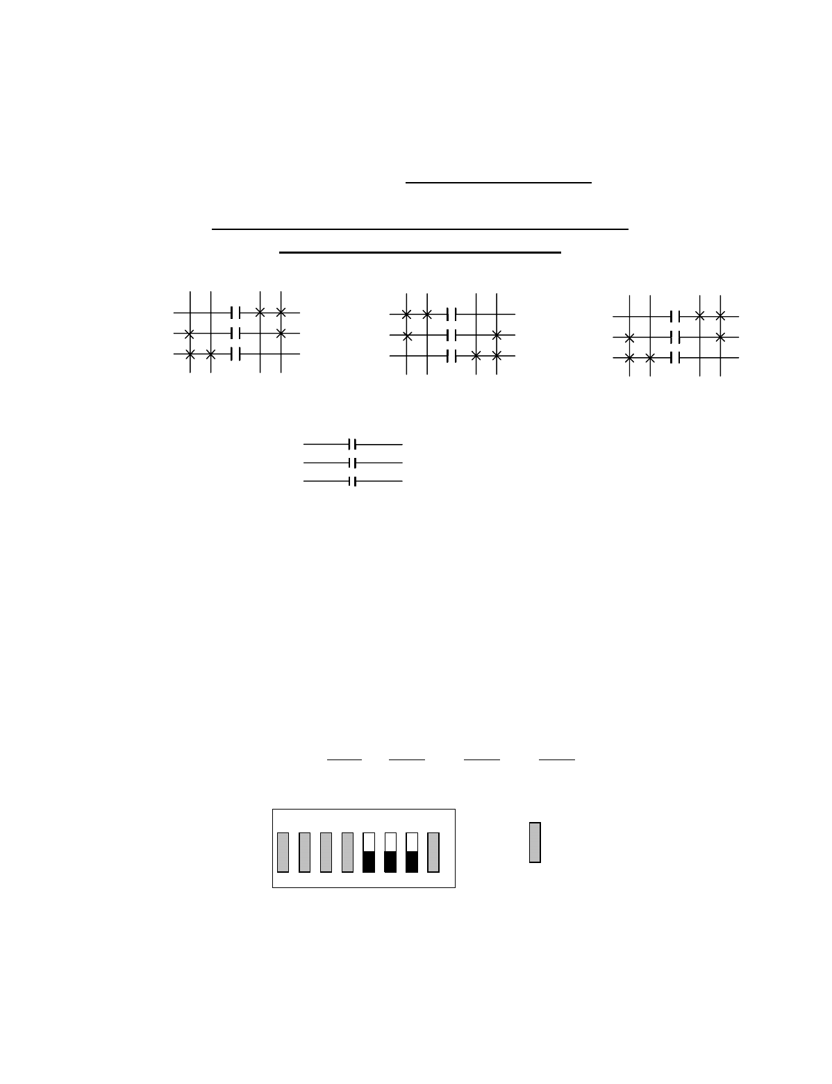
Appendix B - 10K12 2-Speed Membrane Transmitter
Programming (Continued)
B-7
TABLE 1(a)
Crane Control Type Selection: 10K12 2-Speed TYPE 0 PROGRAMMING
____________________________________________________________________________________________________
STANDARD CONFIGURATION: ALL MOTIONS
(HOIST, TROLLEY and BRIDGE)
STANDARD STANDARD OPTIONAL OUTPUT
OUTPUTS OUTPUTS BOARD OPTION #1
A1 AUX 3 (ALARM) B1 HOIST UP C1
A2 AUX 2 (LATCHABLE S2-6) B2 HOIST 2ND SPEED C2
A3 AUX 1 (LATCHABLE S2-7) B3 HOIST DOWN C3 MULTIBOX 1
A4 TROLLEY WEST B4 BRIDGE NORTH C4 MULTIBOX 2
A5 TROLLEY 2ND SPEED B5 BRIDGE 2ND SPEED C5 MULTIBOX 3
A6 TROLLEY EAST B6 BRIDGE SOUTH C6 MULTIBOX 4
Membrane Transmitter and Receiver Switch Select:
Switch settings Sw3-5 to Sw3-7 are defined as follows (for
Optional Output Board in the Receiver Sw3-3 must be
“ON” for Option #1):
TRANSMITTER SWITCH SETTINGS: TYPE Sw3-5 Sw3-6 Sw3-7
0 OFF OFF OFF
NOTE: Transmitter Sw4 positions 1 and 2 must be set to “OFF” for Sw3 to function.
OUTPUTS
B3
B2
B1
HOIST
OUTPUTS
A6
A5
A4
TROLLEY
OUTPUTS
B6
B5
B4
BRIDGE
A3
A2
A1
AUX 1
AUX 2
AUX 3 ALARM
1ST 2ND 1ST 2ND 1ST 2ND
UP DN E W N S
INDEPENDENT OUTPUTS
2ND 1ST 2ND 1ST 2ND 1ST
ON
1 2 3 4 5 6 7 8
OFF
Sw3 For these switch
positions see the
beginning of this
section.
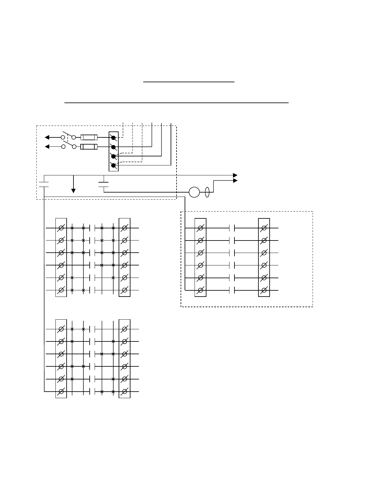
Appendix B - 10K12 2-Speed Membrane Transmitter
Programming (Continued)
B-8
TABLE 1(b)
Crane Control Type Selection: 10K12 TYPE 1 WIRING DIAGRAM
____________________________________________________________________________________________________
2-SPEED with DIRECTIONAL CONTROL: ALL MOTIONS
BJ3
1
2
3
4
5
6
BJ2
1
2
3
4
5
6
K1
K2
K3
K4
K5
K6
2 1 1 2
HOIST
UP
HOIST
2
ND
SPD
HOIST
DOWN
BRIDGE
NORTH
BRIDGE
2
ND
SPD
BRIDGE
SOUTH
•
•
•
•
•
*NOTE:
If it is necessary to operate the Alarm
Function during E-Stop condition, wire the input to the
alarm relay “J3” for the alarm function to the control
power hot side (relay “K1” (MR) on P/S Board de-
energized).
Multibox outputs available with factory
installed Multibox option only.
All connections to outputs AJ2, BJ2 and
CJ2 are to contactors, with proper arc
suppressors across them, controlling the
appropriate listed function to the right.
Telemotive receiver output boards
(E10165-X).
240 VAC 120 VAC
SW1
ON/OFF
TO POWER
TRANSFORMER
E10171-X
P/S BOARD
MAIN LINE
CONTACTOR
TO
CONTROL
POWER
MLC
HOT
RET
(2)
K1 (MR)
(4)
•
•
•
*
See Note
•
240
120
FUSE J1
N
GND
(6)
K1 (MR)
(8)
•
•
•
AJ3
1
2
3
4
5
6
AJ2
1
2
3
4
5
6
2 1 1 2
HOIST
UP/DOWN
TROLLEY
EAST/WEST
BRIDGE
NORTH/SOUTH
TROLLEY
WEST
TROLLEY
2
ND
SPD
TROLLEY
EAST
•
•
•
•
•
•
CJ3
1
2
3
4
5
6
CJ2
1
2
3
4
5
6
K1
K2
K3
K4
K5
K6
OPTIONAL
AUX 1
AUX 2
MULTIBOX 1
or AUX 3
MULTIBOX 2
MULTIBOX 3
MULTIBOX 4
•
•
•
•
•
K1
K2
K3
K4
K5
K6
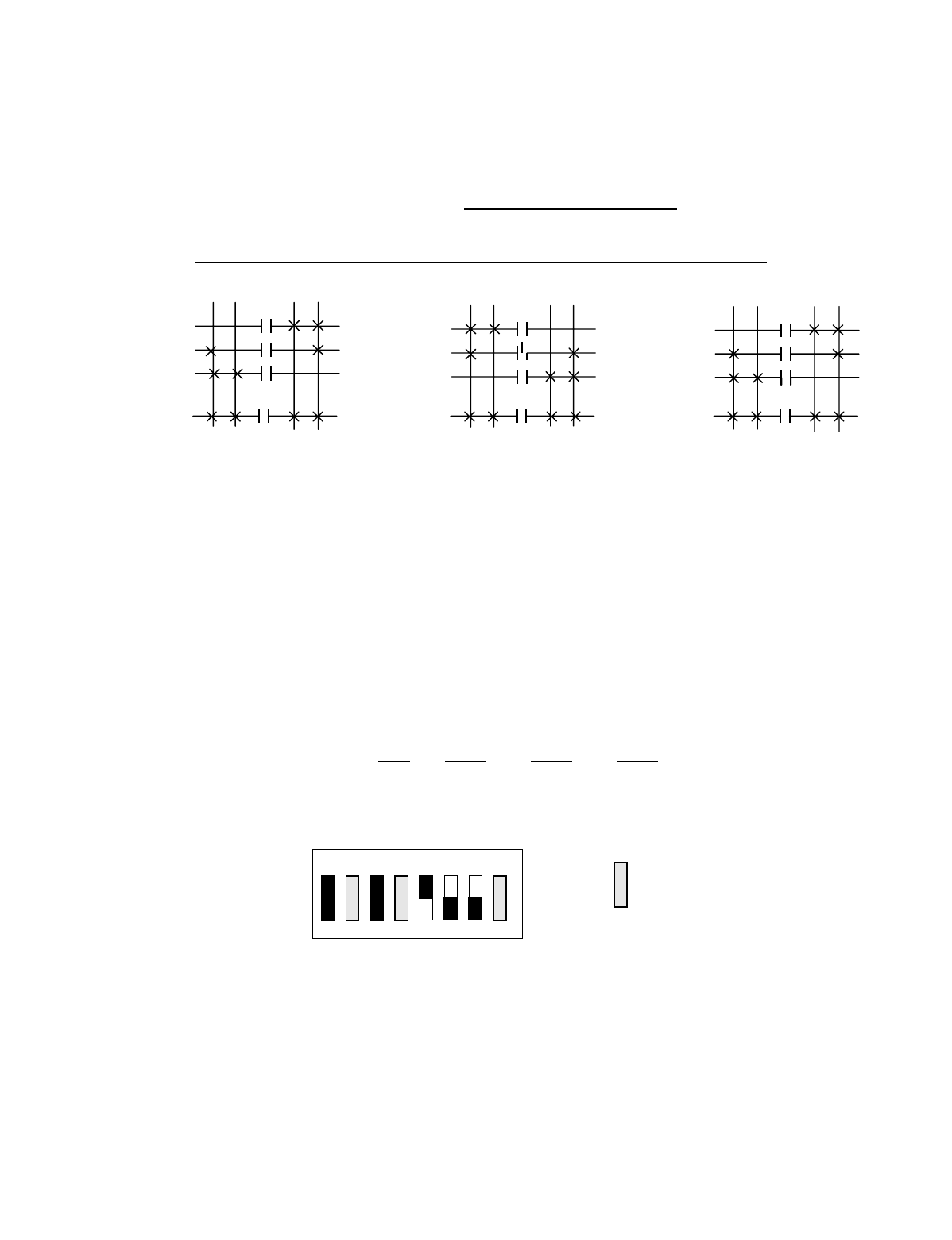
Appendix B - 10K12 2-Speed Membrane Transmitter
Programming (Continued)
B-9
TABLE 1(b)
Crane Control Type Selection: 10K12 2-Speed TYPE 1 PROGRAMMING
____________________________________________________________________________________________________
2-SPEED with DIRECTIONAL CONTROL: ALL MOTIONS
STANDARD STANDARD OPTIONAL OUTPUT OPTIONAL OUTPUT
OUTPUTS OUTPUTS BOARD OPTION #1 BOARD OPTION #2
A1 HOIST UP/DOWN B1 HOIST UP C1 AUX 1 C1 AUX 1
A2 TROLLEY EAST/WEST B2 HOIST 2ND SPEED C2 AUX 3 C2 AUX 2
A3 BRIDGE NORTH/SOUTH B3 HOIST DOWN C3 MULTIBOX 1 C3 AUX 3
A4 TROLLEY WEST B4 BRIDGE NORTH C4 MULTIBOX 2 C4
A5 TROLLEY 2ND SPEED B5 BRIDGE 2ND SPEED C5 MULTIBOX 3 C5
A6 TROLLEY EAST B6 BRIDGE SOUTH C6 MULTIBOX 4 C6
Membrane Transmitter and Receiver Switch Select:
Switch settings Sw3-5 to Sw3-7 are defined as follows (for
Optional Output Board in the Receiver Sw3-3 must be
“ON” for Option #1 and “OFF” for Option #2).
TRANSMITTER SWITCH SETTINGS: Type Sw3-5 Sw3-6 Sw3-7
1ON OFFOFF
NOTE: Transmitter Sw4 positions 1 and 2 must be set to “OFF” for Sw3 to function.
OUTPUTS
B3
B2
B1
A1
HOIST
OUTPUTS
A6
A5
A4
A2
BRIDGE
OUTPUTS
B6
B5
B4
A3
BRIDGE
1
S
T 2ND 1
S
T 2ND 1
S
T 2ND
UP DN E W N S
2ND 1
S
T2ND 1
S
T2ND 1
S
T
ON
OFF
Sw3
For these switch
positions see the
beginning of this
section.
81765432
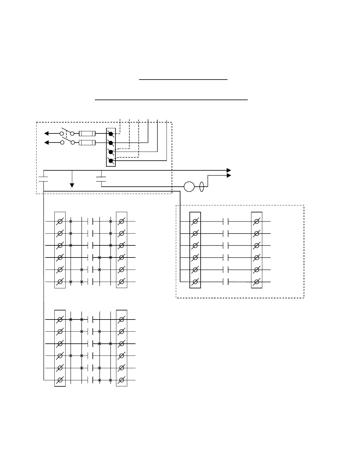
Appendix B - 10K12 2-Speed Membrane Transmitter
Programming (Continued)
B-10
TABLE 1(c)
Crane Control Type Selection: 10K12 TYPE 2 WIRING DIAGRAM
____________________________________________________________________________________________________
2-SPEED, 2-WINDINGS: ALL MOTIONS
BJ3
1
2
3
4
5
6
BJ2
1
2
3
4
5
6
K1
K2
K3
K4
K5
K6
2 1 1 2
HOIST
UP
HOIST
LOW SPD
HOIST
DOWN
BRIDGE
NORTH
BRIDGE
LOW SPD
BRIDGE
SOUTH
•
•
•
•
•
*NOTE:
If it is necessary to operate the Alarm
Function during E-Stop condition, wire the input to the
alarm relay “J3” for the alarm function to the control
power hot side (relay “K1” (MR) on P/S Board de-
energized).
Multibox outputs available with factory
installed Multibox option only.
All connections to outputs AJ2, BJ2 and
CJ2 are to contactors, with proper arc
suppressors across them, controlling the
appropriate listed function to the right.
Telemotive receiver output boards
(E10165-X).
240 VAC 120 VAC
SW1
ON/OFF
TO POWER
TRANSFORMER
E10171-X
P/S BOARD
MAIN LINE
CONTACTOR
TO
CONTROL
POWER
MLC
HOT
RET
(2)
K1 (MR)
(4)
•
•
•
*
See Note
•
240
120
FUSE J1
N
GND
(6)
K1 (MR)
(8)
•
•
•
AJ3
1
2
3
4
5
6
AJ2
1
2
3
4
5
6
2 1 1 2
HOIST
HIGH SPD
TROLLEY
HIGH SPD
BRIDGE
HIGH SPD
TROLLEY
WEST
TROLLEY
2
ND
SPD
TROLLEY
EAST
•
•
•
•
•
•
CJ3
1
2
3
4
5
6
CJ2
1
2
3
4
5
6
K1
K2
K3
K4
K5
K6
OPTIONAL
AUX 1
AUX 2
MULTIBOX 1
or AUX 3
MULTIBOX 2
MULTIBOX 3
MULTIBOX 4
•
•
•
•
•
K1
K2
K3
K4
K5
K6
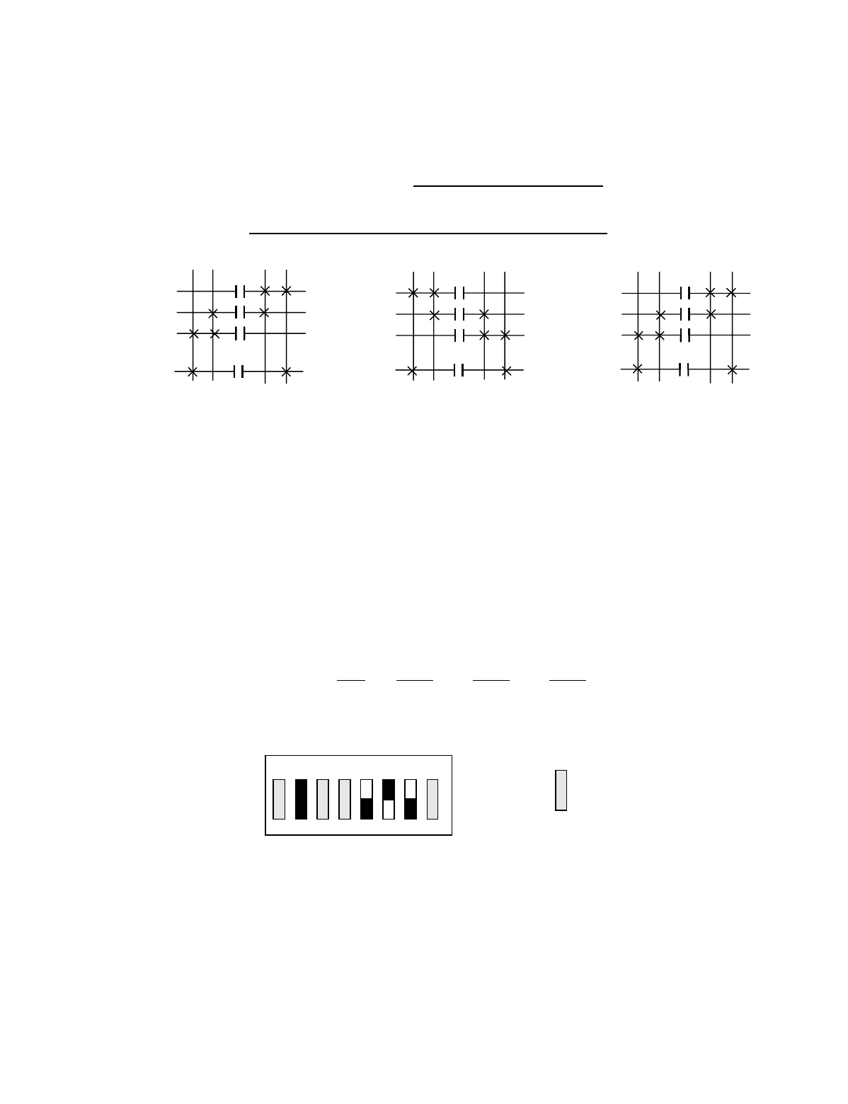
Appendix B - 10K12 2-Speed Membrane Transmitter
Programming (Continued)
B-11
TABLE 1(c)
Crane Control Type Selection: 10K12 2-Speed TYPE 2 PROGRAMMING
____________________________________________________________________________________________________
2-SPEED, 2-WINDINGS: ALL MOTIONS
STANDARD STANDARD OPTIONAL OUTPUT OPTIONAL OUTPUT
OUTPUTS OUTPUTS BOARD OPTION #1 BOARD OPTION #2
A1 HOIST 2ND SPEED B1 HOIST UP C1 AUX 1 C1 AUX 1
A2 TROLLEY 2ND SPEED B2 HOIST 1ST SPEED C2 AUX 2 C2 AUX 2
A3 BRIDGE 2ND SPEED B3 HOIST DOWN C3 MULTIBOX 1 C3 AUX 3
A4 TROLLEY WEST B4 BRIDGE NORTH C4 MULTIBOX 2 C4
A5 TROLLEY 1ST SPEED B5 BRIDGE 1ST SPEED C5 MULTIBOX 3 C5
A6 TROLLEY EAST B6 BRIDGE SOUTH C6 MULTIBOX 4 C6
Membrane Transmitter and Receiver Switch Select:
Switch settings Sw3-5 to Sw3-7 are defined as follows (for
Optional Output Board in the Receiver Sw3-3 must be
“ON” for Option #1 and “OFF” for Option #2):
TRANSMITTER SWITCH SETTINGS: Type Sw3-5 Sw3-6 Sw3-7
2 OFF ON OFF
NOTE: Transmitter Sw4 positions 1 and 2 must be set to “OFF” for Sw3 to function.
OUTPUTS
B3
B2
B1
A1
HOIST
OUTPUTS
A6
A5
A4
A2
TROLLEY
OUTPUTS
B6
B5
B4
A3
BRIDGE
1ST 2ND 1ST 2ND 1ST 2ND
UP DN E W N S
2ND 1ST 2ND 1ST 2ND 1ST
ON
1 2 3 4 5 6 7 8
OFF
Sw3
For these switch
positions see the
beginning of this
section.
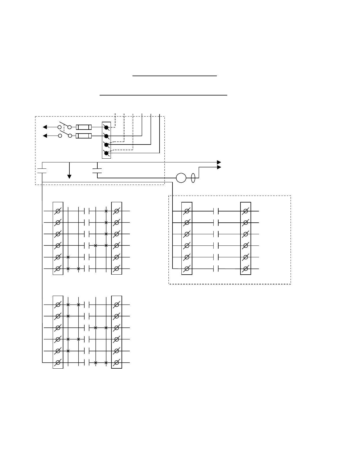
Appendix B - 10K12 2-Speed Membrane Transmitter
Programming (Continued)
B-12
TABLE 1(d)
Crane Control Type Selection: 10K12 TYPE 3 WIRING DIAGRAM
____________________________________________________________________________________________________
ACCO CONTROLS: ALL MOTIONS
BJ3
1
2
3
4
5
6
BJ2
1
2
3
4
5
6
K1
K2
K3
K4
K5
K6
2 1 1 2
HOIST
UP
HOIST UP
2
ND
SPD
HOIST
DOWN
BRIDGE
NORTH
BRIDGE NORTH
2
ND
SPD
BRIDGE
SOUTH
•
•
•
•
•
*NOTE:
If it is necessary to operate the Alarm
Function during E-Stop condition, wire the input to the
alarm relay “J3” for the alarm function to the control
power hot side (relay “K1” (MR) on P/S Board de-
energized).
Multibox outputs available with factory
installed Multibox option only.
All connections to outputs AJ2, BJ2 and
CJ2 are to contactors, with proper arc
suppressors across them, controlling the
appropriate listed function to the right.
Telemotive receiver output boards
(E10165-X).
240 VAC 120 VAC
SW1
ON/OFF
TO POWER
TRANSFORMER
E10171-X
P/S BOARD
MAIN LINE
CONTACTOR
TO
CONTROL
POWER
MLC
HOT
RET
(2)
K1 (MR)
(4)
•
•
•
*
See Note
•
240
120
FUSE J1
N
GND
(6)
K1 (MR)
(8)
•
•
•
AJ3
1
2
3
4
5
6
AJ2
1
2
3
4
5
6
2 1 1 2
HOIST DOWN
2
ND
SPEED
TROLLEY WEST
2
ND
SPD
BRIDGE SOUTH
2
ND
SPD
TROLLEY
WEST
TROLLEY EAST
2
ND
SPD
TROLLEY
EAST
•
•
•
•
•
•
CJ3
1
2
3
4
5
6
CJ2
1
2
3
4
5
6
K1
K2
K3
K4
K5
K6
OPTIONAL
AUX 1
AUX 2
MULTIBOX 1
or AUX 3
MULTIBOX 2
MULTIBOX 3
MULTIBOX 4
•
•
•
•
•
K1
K2
K3
K4
K5
K6
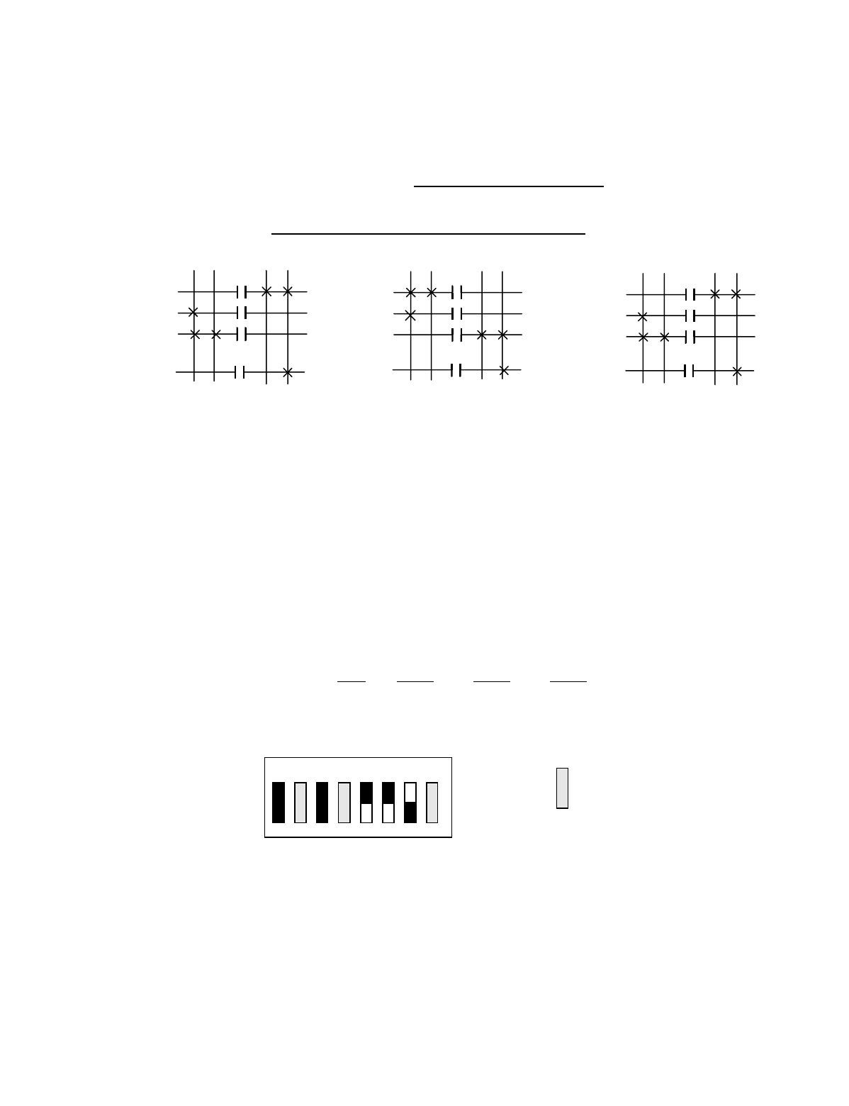
Appendix B - 10K12 2-Speed Membrane Transmitter
Programming (Continued)
B-13
TABLE 1(d)
Crane Control Type Selection: 10K12 2-Speed TYPE 3 PROGRAMMING
____________________________________________________________________________________________________
ACCO CONTROLS: ALL MOTIONS
STANDARD STANDARD OPTIONAL OUTPUT OPTIONAL OUTPUT
OUTPUTS OUTPUTS BOARD OPTION #1 BOARD OPTION #2
A1 HOIST DOWN 2ND SPEED B1 HOIST UP C1 AUX 1 C1 AUX 1
A2 TROLLEY WEST 2ND SPEED B2 HOIST UP 2ND SPEED C2 AUX 2 C2 AUX 2
A3 BRIDGE SOUTH 2ND SPEED B3 HOIST DOWN C3 MULTIBOX 1 C3 AUX 3
A4 TROLLEY WEST B4 BRIDGE NORTH C4 MULTIBOX 2 C4
A5 TROLLEY EAST 2ND SPEED B5 BRIDGE NORTH 2ND SPEED C5 MULTIBOX 3 C5
A6 TROLLEY EAST B6 BRIDGE SOUTH C6 MULTIBOX 4 C6
Membrane Transmitter and Receiver Switch Select:
Switch settings Sw3-5 to Sw3-7 are defined as follows (for
Optional Output Board in the Receiver Sw3-3 must be
“ON” for Option #1 and “OFF” for Option #2):
TRANSMITTER SWITCH SETTINGS: Type Sw3-5 Sw3-6 Sw3-7
3ON ON OFF
NOTE: Transmitter Sw4 positions 1 and 2 must be set to “OFF” for Sw3 to function.
OUTPUTS
B3
B2
B1
A1
HOIST
OUTPUTS
A6
A5
A4
A2
TROLLEY
OUTPUTS
B6
B5
B4
A3
BRIDGE
1ST 2ND 1ST 2ND 1
S
T 2ND
UP DN E W N S
2ND 1ST 2ND 1ST 2ND 1
S
T
ON
OFF
Sw3
For these switch
positions see the
beginning of this
section.
81765432
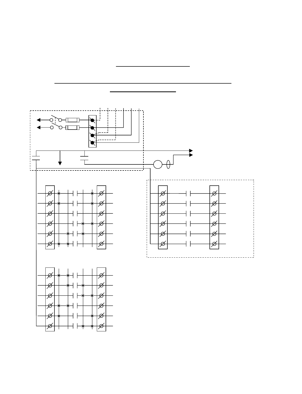
Appendix B - 10K12 2-Speed Membrane Transmitter
Programming (Continued)
B-14
TABLE 1(e)
Crane Control Type Selection: 10K12 TYPE 4 WIRING DIAGRAM
____________________________________________________________________________________________________
P&H: 2-SPEED, 2-WINDINGS for HOIST and TROLLEY:
STANDARD BRIDGE
BJ3
1
2
3
4
5
6
BJ2
1
2
3
4
5
6
K1
K2
K3
K4
K5
K6
2 1 1 2
HOIST
UP
HOIST
LOW SPD
HOIST
DOWN
BRIDGE
NORTH
BRIDGE
LOW SPD
BRIDGE
SOUTH
•
•
•
•
•
*NOTE:
If it is necessary to operate the Alarm
Function during E-Stop condition, wire the input to the
alarm relay “J3” for the alarm function to the control
power hot side (relay “K1” (MR) on P/S Board de-
energized).
Multibox outputs available with factory
installed Multibox option only.
All connections to outputs AJ2, BJ2 and
CJ2 are to contactors, with proper arc
suppressors across them, controlling the
appropriate listed function to the right.
Telemotive receiver output boards
(E10165-X).
240 VAC 120 VAC
SW1
ON/OFF
TO POWER
TRANSFORMER
E10171-X
P/S BOARD
MAIN LINE
CONTACTOR
TO
CONTROL
POWER
MLC
HOT
RET
(2)
K1 (MR)
(4)
•
•
•
*
See Note
•
240
120
FUSE J1
N
GND
(6)
K1 (MR)
(8)
•
•
•
AJ3
1
2
3
4
5
6
AJ2
1
2
3
4
5
6
2 1 1 2
HOIST
HIGH SPD
TROLLEY
HIGH SPD
AUX 1
TROLLEY
WEST
TROLLEY
LOW SPD
TROLLEY
EAST
•
•
•
•
•
•
CJ3
1
2
3
4
5
6
CJ2
1
2
3
4
5
6
K1
K2
K3
K4
K5
K6
OPTIONAL
AUX 2
AUX 3
MULTIBOX 1
MULTIBOX 2
MULTIBOX 3
MULTIBOX 4
•
•
•
•
•
K1
K2
K3
K4
K5
K6

Appendix B - 10K12 2-Speed Membrane Transmitter
Programming (Continued)
B-15
TABLE 1(e)
Crane Control Type Selection: 10K12 2-Speed TYPE 4 PROGRAMMING
____________________________________________________________________________________________________
P&H: 2-SPEED, 2-WINDINGS for HOIST and TROLLEY:
STANDARD BRIDGE
STANDARD STANDARD OPTIONAL OUTPUT OPTIONAL OUTPUT
OUTPUTS OUTPUTS BOARD OPTION #1 BOARD OPTION #2
A1 HOIST 2ND SPEED B1 HOIST UP C1 AUX 2 C1 AUX 2
A2 TROLLEY 2ND SPEED B2 HOIST 1ST SPEED C2 AUX 3 C2 AUX 3
A3 AUX 1 (LATCHABLE S2-7) B3 HOIST DOWN C3 MULTIBOX 1 C3
A4 TROLLEY WEST B4 BRIDGE NORTH C4 MULTIBOX 2 C4
A5 TROLLEY 1ST SPEED B5 BRIDGE 2ND SPEED C5 MULTIBOX 3 C5
A6 TROLLEY EAST B6 BRIDGE SOUTH C6 MULTIBOX 4 C6
Membrane Transmitter and Receiver Switch Select:
Switch settings Sw3-5 to Sw3-7 are defined as follows (for
Optional Output Board in the Receiver Sw3-3 must be
“ON” for Option #1 and “OFF” for Option #2):
TRANSMITTER SWITCH SETTINGS: Type Sw3-5 Sw3-6 Sw3-7
4OFF OFF ON
NOTE: Transmitter Sw4 positions 1 and 2 must be set to “OFF” for Sw3 to function.
OUTPUTS
B3
B2
B1
A1
HOIST
OUTPUTS
A6
A5
A4
A2
TROLLEY
OUTPUTS
B6
B5
B4
BRIDGE
1ST 2ND 1ST 2ND
1ST 2ND
UP DN E W N S
2ND 1ST 2ND 1ST
2ND 1ST
A3 AUX 1
INDEPENDENT OUTPUTS
ON
OFF
Sw3
For these switch
positions see the
beginning of this
section.
81765432
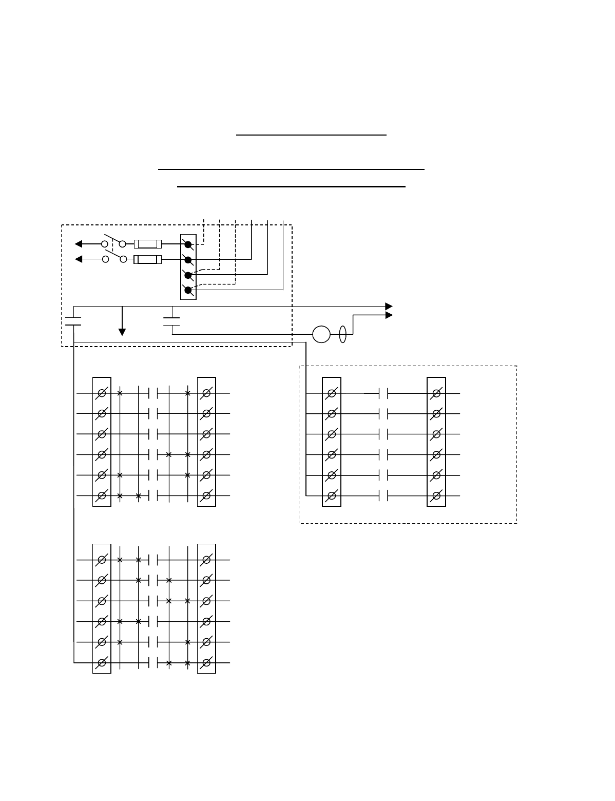
Appendix B - 10K12 2-Speed Membrane Transmitter
Programming (Continued)
B-16
TABLE 1(f)
Crane Control Type Selection: 10K12 TYPE 5 WIRING DIAGRAM
____________________________________________________________________________________________________
P&H: 2-SPEED, 2-WINDINGS for HOIST:
STANDARD TROLLEY and BRIDGE
BJ3
1
2
3
4
5
6
BJ2
1
2
3
4
5
6
K1
K2
K3
K4
K5
K6
2 1 1 2
HOIST
UP
HOIST
LOW SPD
HOIST
DOWN
BRIDGE
NORTH
BRIDGE
2
ND
SPD
BRIDGE
SOUTH
•
•
•
•
•
*NOTE:
If it is necessary to operate the Alarm
Function during E-Stop condition, wire the input to the
alarm relay “J3” for the alarm function to the control
power hot side (relay “K1” (MR) on P/S Board de-
energized).
Multibox outputs available with factory
installed Multibox option only.
All connections to outputs AJ2, BJ2 and
CJ2 are to contactors, with proper arc
suppressors across them, controlling the
appropriate listed function to the right.
Telemotive receiver output boards
(E10165-X).
240 VAC 120 VAC
SW1
ON/OFF
TO POWER
TRANSFORMER
E10171-X
P/S BOARD
MAIN LINE
CONTACTOR
TO
CONTROL
POWER
MLC
HOT
RET
(2)
K1 (MR)
(4)
•
•
•
*
See Note
•
240
120
FUSE J1
N
GND
(6)
K1 (MR)
(8)
•
•
•
AJ3
1
2
3
4
5
6
AJ2
1
2
3
4
5
6
2 1 1 2
HOIST
HIGH SPD
AUX 2
AUX 1
TROLLEY
WEST
TROLLEY
2
ND
SPD
TROLLEY
EAST
•
•
•
•
•
•
CJ3
1
2
3
4
5
6
CJ2
1
2
3
4
5
6
K1
K2
K3
K4
K5
K6
OPTIONAL
AUX 3
MULTIBOX 1
MULTIBOX 2
MULTIBOX 3
MULTIBOX 4
•
•
•
•
•
K1
K2
K3
K4
K5
K6
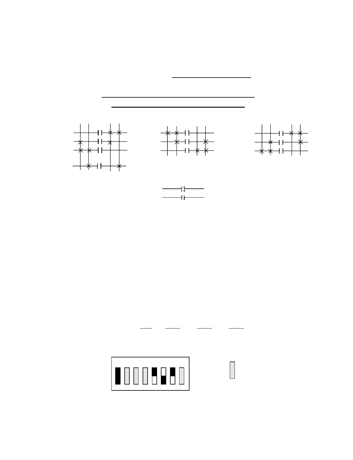
Appendix B - 10K12 2-Speed Membrane Transmitter
Programming (Continued)
B-17
TABLE 1(f)
Crane Control Type Selection: 10K12 2-Speed TYPE 5 PROGRAMMING
____________________________________________________________________________________________________
P&H: 2-SPEED, 2-WINDINGS for HOIST:
STANDARD TROLLEY and BRIDGE
STANDARD STANDARD OPTIONAL OUTPUT OPTIONAL OUTPUT
OUTPUTS OUTPUTS BOARD OPTION #1 BOARD OPTION #2
A1 HOIST 2ND SPEED B1 HOIST UP C1 AUX 3 C1 AUX 3
A2 AUX 2 (LATCHABLE S2-6) B2 HOIST 1ST SPEED C2 C2
A3 AUX 1 (LATCHABLE S2-7) B3 HOIST DOWN C3 MULTIBOX 1 C3
A4 TROLLEY WEST B4 BRIDGE NORTH C4 MULTIBOX 2 C4
A5 TROLLEY 2ND SPEED B5 BRIDGE 2ND SPEED C5 MULTIBOX 3 C5
A6 TROLLEY EAST B6 BRIDGE SOUTH C6 MULTIBOX 4 C6
Membrane Transmitter and Receiver Switch Select:
Switch settings Sw3-5 to Sw3-7 are defined as follows (for
Optional Output Board in the Receiver Sw3-3 must be
“ON” for Option #1 and “OFF” for Option #2):
TRANSMITTER SWITCH SETTINGS: Type Sw3-5 Sw3-6 Sw3-7
5ON OFF ON
NOTE: Transmitter Sw4 positions 1 and 2 must be set to “OFF” for Sw3 to function.
OUTPUTS
B3
B2
B1
A1
HOIST
OUTPUTS
A6
A5
A4
TROLLEY
OUTPUTS
B6
B5
B4
BRIDGE
1ST 2ND
1
S
T 2ND 1
S
T 2ND
UP DN E W N S
2ND 1ST
2ND 1
S
T2ND 1
S
T
A3
A2
AUX 1
AUX 2
INDEPENDENT OUTPUTS
ON
OFF
Sw3
For these switch
positions see the
beginning of this
section.
81765432
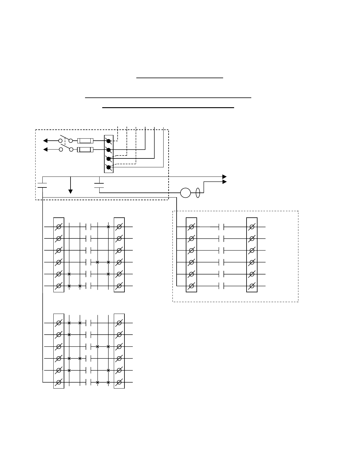
Appendix B - 10K12 2-Speed Membrane Transmitter
Programming (Continued)
B-18
TABLE 1(g)
Crane Control Type Selection: 10K12 TYPE 6 WIRING DIAGRAM
____________________________________________________________________________________________________
DEMAG: 2-SPEED, 2-WINDINGS for HOIST:
STANDARD TROLLEY and BRIDGE
BJ3
1
2
3
4
5
6
BJ2
1
2
3
4
5
6
K1
K2
K3
K4
K5
K6
2 1 1 2
HOIST UP
HOIST UP
2
ND
SPD
HOIST DOWN
BRIDGE
NORTH
BRIDGE
2
ND
SPD
BRIDGE
SOUTH
•
•
•
•
•
*NOTE:
If it is necessary to operate the Alarm
Function during E-Stop condition, wire the input to the
alarm relay “J3” for the alarm function to the control
power hot side (relay “K1” (MR) on P/S Board de-
energized).
Multibox outputs available with factory
installed Multibox option only.
All connections to outputs AJ2, BJ2 and
CJ2 are to contactors, with proper arc
suppressors across them, controlling the
appropriate listed function to the right.
Telemotive receiver output boards
(E10165-X).
240 VAC 120 VAC
SW1
ON/OFF
TO POWER
TRANSFORMER
E10171-X
P/S BOARD
MAIN LINE
CONTACTOR
TO
CONTROL
POWER
MLC
HOT
RET
(2)
K1 (MR)
(4)
•
•
•
*
See Note
•
240
120
FUSE J1
N
GND
(6)
K1 (MR)
(8)
•
•
•
AJ3
1
2
3
4
5
6
AJ2
1
2
3
4
5
6
2 1 1 2
HOIST DOWN
2
ND
SPD
AUX 2
AUX 1
TROLLEY
WEST
TROLLEY
2
ND
SPD
TROLLEY
EAST
•
•
•
•
•
•
CJ3
1
2
3
4
5
6
CJ2
1
2
3
4
5
6
K1
K2
K3
K4
K5
K6
OPTIONAL
AUX 3
MULTIBOX 1
MULTIBOX 2
MULTIBOX 3
MULTIBOX 4
•
•
•
•
•
K1
K2
K3
K4
K5
K6

Appendix B - 10K12 2-Speed Membrane Transmitter
Programming (Continued)
B-19
TABLE 1(g)
Crane Control Type Selection: 10K12 TYPE 6 PROGRAMMING
____________________________________________________________________________________________________
DEMAG: 2-SPEED, 2-WINDINGS for HOIST:
STANDARD TROLLEY and BRIDGE
STANDARD STANDARD OPTIONAL OUTPUT OPTIONAL OUTPUT
OUTPUTS OUTPUTS BOARD OPTION #1 BOARD OPTION #2
A1 HOIST DOWN 2ND SPEED B1 HOIST UP C1 AUX 3 C1 AUX 3
A2 AUX 2 (LATCHABLE S2-6) B2 HOIST UP 2ND SPEED C2 C2
A3 AUX 1 (LATCHABLE S2-7) B3 HOIST DOWN C3 MULTIBOX 1 C3
A4 TROLLEY WEST B4 BRIDGE NORTH C4 MULTIBOX 2 C4
A5 TROLLEY 2ND SPEED B5 BRIDGE 2ND SPEED C5 MULTIBOX 3 C5
A6 TROLLEY EAST B6 BRIDGE SOUTH C6 MULTIBOX 4 C6
Membrane Transmitter and Receiver Switch Select:
Switch settings Sw3-5 to Sw3-7 are defined as follows (for
Optional Output Board in the Receiver Sw3-3 must be
“ON” for Option #1 and “OFF” for Option #2):
TRANSMITTER SWITCH SETTINGS: Type Sw3-5 Sw3-6 Sw3-7
6 OFF ON ON
NOTE: Transmitter Sw4 positions 1 and 2 must be set to “OFF” for Sw3 to function.
OUTPUTS
B3
B2
B1
A1
HOIST
OUTPUTS
A6
A5
A4
TROLLEY
OUTPUTS
B6
B5
B4
BRIDGE
1ST 2ND
1ST 2ND 1
S
T 2ND
UP DN E W N S
2ND 1ST
2ND 1ST 2ND 1
S
T
A3
A2
AUX 1
AUX 2
INDEPENDENT OUTPUTS
ON
OFF
Sw3
For these switch
positions see the
beginning of this
section.
81765432
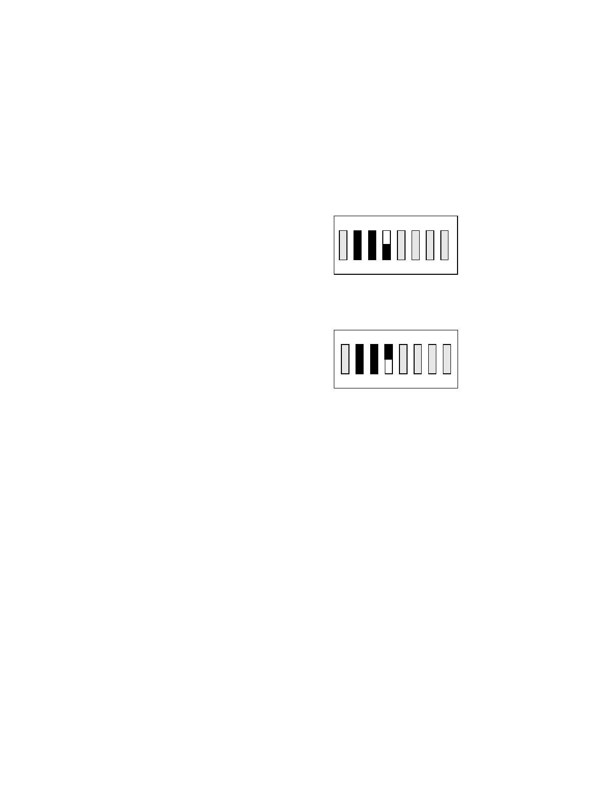
Appendix B - 10K12 2-Speed Membrane Transmitter
Programming (Continued)
B-20
TABLE 1(h)
Time-out –timer disable for 2-speed membrane transmitter only.
____________________________________________________________________________________________________
Sw3 position 4 can disable the transmitter time-out-timer.
Sw3
Transmitter time-out-timer active.
Sw3
Transmitter time-out-timer turned off.
NOTE: Transmitter Sw4 positions 1 and 2 must be set to “OFF” for Sw3 to function.
ON
OFF
81765432
ON
OFF
81765432
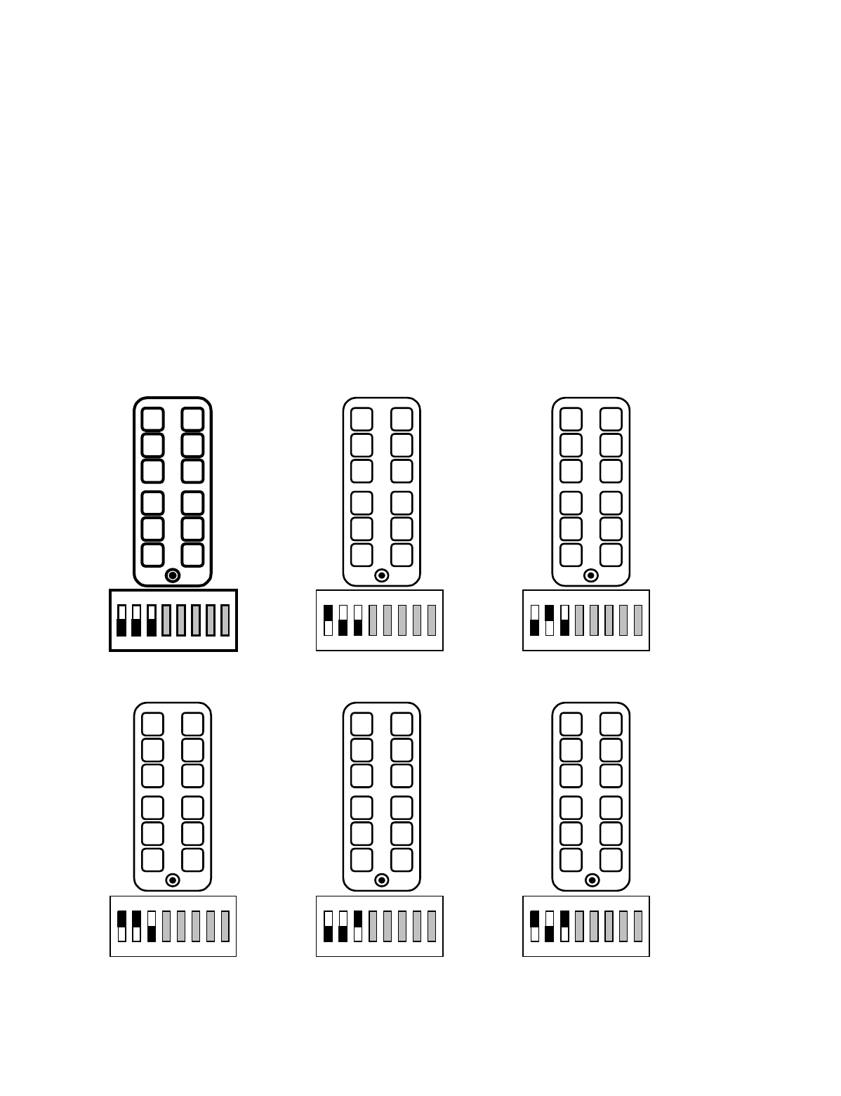
Appendix B - 10K12 2-Speed Membrane Transmitter
Programming (Continued)
B-21
TABLE 1(i)
Repositioning of transmitter pushbutton switch functions for 2-speed membrane transmitter only.
____________________________________________________________________________________________________
Sw3 positions 1 through 3 can change the functional positions of the switches controlling bridge, hoist and trolley. This can
be useful to align East/West and North/South. This reconfiguration does NOT affect receiver wiring.
____________________________________________________________________________________________________
WARNING
CHANGING THESE SWITCHES CHANGES THE FUCTIONAL OPERATION OF THE CRANE IN RELATIONSHIP TO
THE TRANSMITTER BUTTON BEING DEPRESSED. THE FUNCTIONAL OPERATION OF THE CRANE SHOULD
NEVER BE CHANGED WITHOUT ALL PERSONNEL RESPONSIBLE FOR CRANE OPERATION BEING NOTIFIED
PRIOR TO MODIFICATION.
HOIST
TROLLEY
BRIDGE
HOIST
BRIDGE
TROLLEY
TROLLEY
BRIDGE
HOIST
1 2 3 4 5 6 7 8 1 2 3 4 5 6 7 8 1 2 3 4 5 6 7 8
TROLLEY
HOIST
BRIDGE
BRIDGE
HOIST
TROLLEY
BRIDGE
TROLLEY
HOIST
1 2 3 4 5 6 7 8 1 2 3 4 5 6 7 8 1 2 3 4 5 6 7 8
Standard Configuration
ON
OFF
ON
OFF
ON
OFF
ON
OFF
ON
OFF
ON
OFF

Appendix B - 10K12 2-Speed Membrane Transmitter
Programming (Continued)
B-22
This Page Intentionally Left Blank

C-1
NOTE: This section also contains information on Optional Output Board for Multibox and other
optional outputs for use with the 10K16.
Appendix C - 10K16/24 Pendant and SLTX
Transmitter Programming

Appendix C - 10K16/24 Pendant and SLTX
Transmitter Programming (Continued)
C-2
C-1. Transmitter Switches Sw3 and Sw4
Programming. (See Sections 6-2 and 6-4 for
physical location of transmitter switches).
C-1.1. Transmitter programming Sw3
C-1.1.1. Positions 1-3 (Pendant only) Switch
Positioning. (Standard configuration all
“OFF”).
The functional positions of the various buttons controlling
the hoist trolley and bridge can be moved by transmitter dip
switch Sw3 also. Positions Sw3-1 through Sw3-3 control
these functions. No change in receiver wiring is needed to
use these functions. See TABLE 2(k) for switch verses but-
ton configurations.
C-1.1.2. Positions 1-3 (SLTX only) no function.
(Keep turned “OFF”).
C-1.1.3. Positions 4-7 no function. (Keep
turned “OFF”).
C-1.1.4. Position 8 Time-out-timer Disable.
(Normally keep turned “OFF”).
The transmitter has an approximate 15-minute time-out-
timer. If the transmitter is not used for over 15 minutes it
will shut down. This transmitter time-out-timer function is
transmitter dip switch selectable. Sw3 position 8 disables
the time-out-timer. Turning Sw3-8 “ON” disables the time-
out-timer.
C-1.2. Transmitter programming Sw4
C-1.2.1. Position 1-2 Mode Enable. (Standard
Mode 1 keep 1-2 turned “OFF”).
Mode 1, Sw4 1-2 all “OFF”. The 10K16 3-speed system
comes standard configured this way from the factory with
three 3-speed controls and four auxiliaries. The 10K24 3-
speed system comes standard configured this way from the
factory with five 3-speed controls and four auxiliaries.
Mode 2, Sw4 1 turned “ON” and Sw4 2 turned “OFF”. The
10K24 configured this way gives hoist, trolley and bridge
with independent select functions. The system utilizes sep-
arate select relays with common speed and direction.
Mode 3, Sw4 1 turned “OFF” and Sw4 2 turned “ON”. The
10K24 configured this way is four motor 3-speed selectable
by the rotary switch. Two hoists, one trolley and one bridge
with main hoist (H1), auxiliary hoist (H2), and “both” (B)
main and auxiliary hoists are selectable by the rotary switch.
C-1.2.2. Position 3 Disable Tandem for hoist
and trolley. (Normally keep turned “OFF”).
For cranes with auxiliary hoists and/or trolleys, turning this
switch “ON” disables the transmitter selector switch “B”
position (both function) that selects tandem operation of
hoist or trolley.
C-1.2.3. Position 4 Invert Crane Select Aux.
Outputs. (Normally keep turned “OFF”).
For cranes that use the select function only, turning this
switch “ON” inverts the select function operation so that the
relay closes for the unselected function.
C-1.2.4. Positions 5-7 Extended Crane Control
Configurations. (Standard all “OFF”
otherwise see TABLES 1 and 2)
The 10K16/24 Pendant and SLTX transmitter is available
with extended crane control configurations. These options
are switch configurable on the transmitter. The eight-posi-
tion dip switches Sw3 and Sw4 can provide all configura-
tions with a single transmitter CPU EPROM. TABLES 1
and 2 show the available configurations and the switch pro-
gramming needed to provide them. The standard transmit-
ter comes with the output configuration shown either in
TABLE 1(a) or TABLE 2(a): TYPE 0 and has no extended
crane control configurations. For extended crane control
configurations: See TABLE 1 or TABLE 2: TYPE 1
through CONFIGURATION 4 respectively. If a configura-
tion listed in these TABLES is preferred over the standard
configuration, please reprogram Sw3 and Sw4 respectively
in the transmitter.
C-1.2.5. Position 8 no function. (Keep turned
“OFF”).

Appendix C - 10K16/24 Pendant and SLTX
Transmitter Programming (Continued)
C-3
C-2. Replacement Transmitter EPROM’s
All 10K16/24 Pendant (10K12 Pendant transmitters nor-
mally have a black top and a yellow bottom. 10K16/24 pen-
dant transmitters normally have a yellow top and black
bottom.) and SLTX transmitters use CPU EPROM part
numbers as listed below:
Pendant 3 Motor Three speed 10K16/18 FW10K16P-1
Pendant 4/5 Motor Three speed 10K24 FW10K24P-2
Pendant 7 Motor Three speed 10K24 FW2797-1
SLTX 3 Motor Three speed 10K16/18 FW2819-0
SLTX 3/4/5 Motor Three speed 10K24 FW2820-0
SLTX 3/4/5 Motor Five speed 10K24 FW2818-0
C-3. Multibox and Optional Output Board:
WARNING
IF YOUR UNIT WAS NOT ORDERED WITH MULTI-
BOX DO NOT ATTEMPT TO PROGRAM MULTIBOX
IN THE FIELD. TELEMOTIVE MUST COORDINATE
ACCESS CODE ASSIGNMENTS WITH THE TRANS-
MITTERS PRIOR TO ENABLING MULTIBOX.
PLEASE CONTACT TELEMOTIVE IF YOU NEED TO
ADD MULTIBOX. FAILURE TO DO SO CAN BE A
SERIOUS SAFETY HAZARD.
If Multibox is used (Receiver CPU Board switch Sw3-3 is
“ON” and the Optional Output Board is installed in the
receiver for 10K16). The outputs are as follows:
C1 MULTIBOX 1
C2 MULTIBOX 2
C3 MULTIBOX 3
C4 MULTIBOX 4
C-3.1. 10K16 Only
C5-C6 NO FUNCTION
C7 AUX 5
C8 AUX 6
C-3.2. 10K24 Only
Without Multibox most of the 10K24 configurations have
the first 4 relays C1-C4 as Aux Hoist and the second four
relays C5-C8 as Aux Trolley. For those systems that are 4
relays Aux Hoist and four relays Aux Trolley Multibox uses
the first four positions C1-C4 thus eliminating them for
motion control. Leaving the last four C5-C8 for either Aux
Hoist or Aux Trolley. S3 position 4 on the Receiver CPU
Board selects either Aux Trolley S3-4 “OFF” or Aux Hoist
S3-4 “ON” functions on relays C5-C8.
C-4. Latching of Auxiliary Relays
Certain auxiliary relays can be set to latch (be toggled on
and off) by setting dip switch S2 positions 6-8 on the
Receiver CPU Board. If an Aux function is latchable it is
noted in the programming diagram by the following note
(LATCHABLE S2-#) where # is the switch position 6-8 that
must be turned on for the latching function.
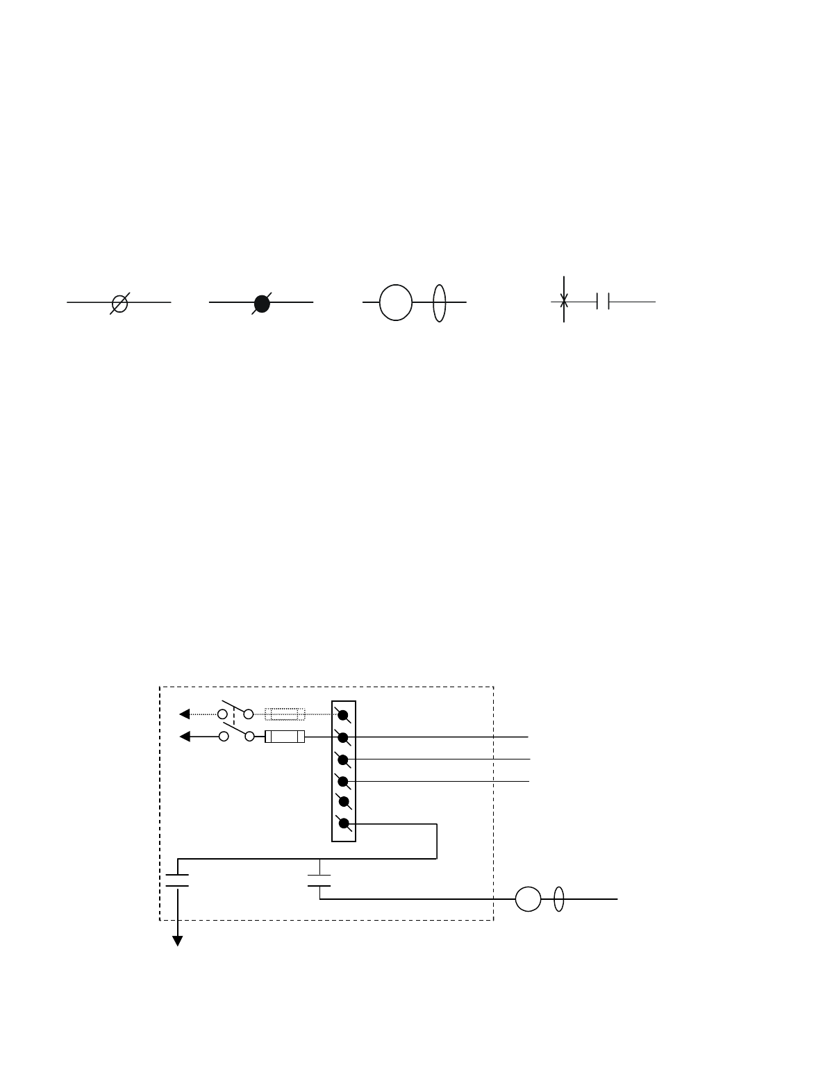
Appendix C - 10K16/24 Pendant and SLTX
Transmitter Programming (Continued)
C-4
C-5. TABLE 1(a) through TABLE 1(g) Wiring
and Programming Diagrams
The following tables give various extended crane configura-
tions. Functional terms like Trolley South and Hoist Up
match standard transmitter labeling from the factory. The
following legend is used in these diagrams:
In the following wiring diagrams the relay outputs AJ2, BJ2
and CJ2 have listed to the right of the output terminal the
appropriate motor function they control, i.e., trolley, hoist
etc. Proper installation requires that this output be wired to
a contactor controlling that function and that the contactor
has the proper arc suppressor across it. The relays on these
output boards are rated at 16 amps and fused at 10 amps
unless otherwise noted.
C-6. Optional 110 Volt Wiring
Power supply wiring is accomplished through connector J1
on the power supply board. The connections labeled 240,
120, N and GND are wired to the appropriate supply con-
nections per the wiring diagrams. An extra connection 120
is provided for 120 Volt applications only for jumpering to
Pins 2 and 6 of the Master Relay (MR) K1 on the power
supply board. The unit may optionally be wired as in Figure
C-1. Figure C-2 shows the wiring layout for the 10K16 and
Figure C-3 shows the wiring layout for the 10K24. All
other wiring is accomplished per the attached tables.
Figure C-1. Optional 120 VAC Wiring
#
Indicates terminal
block J2 or J3 with
terminal number #
in the radio receiver
output board
GND
Indicates terminal
block J1 in power
supply board with
the required con-
nection noted.
Indicates customer
supplied contactor coil
with arc suppressor in
parallel.
MLC
Indicates a relay contact in radio
receiver number #. The X
indicates the relay closing and the
closing sequence (1
st
, 2
nd
, etc.) as
the indicated switch is de
p
ressed.
K#
1
ST
SW1
ON/OFF
E10171-X
P/S BOARD
(2)
K1 (M R)
(4)
•
•
120
FUSE J1
N
GND
N
120
(6)
K1 (M R)
(8)
•
•
•
120 VAC
MLC
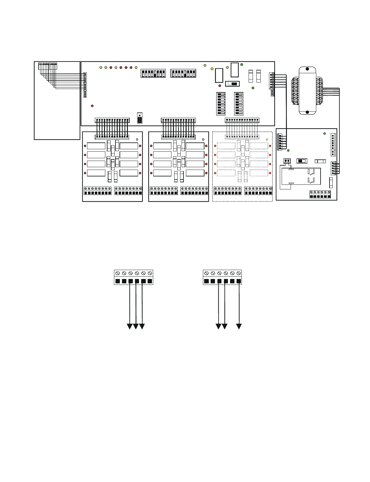
Appendix C - 10K16/24 Pendant and SLTX
Transmitter Programming (Continued)
C-5
Figure C-2. 10K16 Wiring Layout
C-7. Crane Control Type Selection
The crane control type selection information is provided in
TABLE 1(a) through TABLE 2(k). Each table defines a
specific configuration and provides a wiring diagram, a pro-
gramming diagram, and a transmitter and receiver switch
settings. The table for each configuration is provided on
facing pages so that all information is easily accessible.
J1 Power Supply
Board
NGNDN120 240120
Ground
Neutral
120VAC
NGNDN120 240120
Ground
240VAC B
240VAC A
220 VAC Wirin
g
110 VAC Wirin
g
J2
1 2 3 4 5 6 7 8 1 2 3 4 5 6 7 8
J3
DS9
DS1DS2DS3DS4
K1
K2
K3
K4
K5
K6
K7
K8
F1
F2
F3
F4 F5
F6
F7
F8
DS5 DS6 DS7 DS8
J1
RELAY BOARD
J2
1 2 3 4 5 6 7 8 1 2 3 4 5 6 7 8
J3
DS9
DS1DS2DS3DS4
K1
K2
K3
K4
K5
K6
K7
K8
F1
F2
F3
F4 F5
F6
F7
F8
DS5 DS6 DS7 DS8
J1
RELAY BOARD
J5
F2
DS2
DS
1SW1
ON OFF
J2
J3 J7
POWER
SUPPLY
BOARD
RECEIVER BOARD
T
R
A
N
S
F
O
R
M
E
R
J3
J4
DS-15
DS2
K
1
S1
DS5
DS4 DS1
DS3
J7 J8 J6
87654321
87654 321
0FF 0FF
S3 S2
0FF
87654 321
S5
87654321
S4
0FF
DS-7 -8 -9 -10 -11-12 -13-14
J5
JU2
J2
J1
K
2
DS6
ON
CPU BOARD
F1
J6
J1
NGNDN120 240120
2
86
4
MASTER
CONTROL
RELAY
(MCR)
K1
OUTPUTS INPUTS OUTPUTS INPUTS OUTPUTS INPUTS
Position A Position B Position C
BA
F2 F1
OPTIONAL OUTPUT BOARD
J2
1 2 3 4 5 6 7 8 1 2 3 4 5 6 7 8
J3
DS9
DS1 DS2 DS3 DS4
K1
K2
K3
K4
K5
K6
K7
K8
F1
F2
F3
F4 F5
F6
F7
F8
DS5 DS6 DS7 DS8
J1
RELAY BOARD
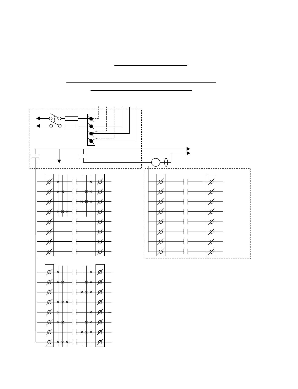
Appendix C - 10K16/24 Pendant and SLTX
Transmitter Programming (Continued)
C-6
TABLE 1(a)
Crane Control Type Selection: 10K16 TYPE 0 WIRING DIAGRAM
____________________________________________________________________________________________________
STANDARD CONFIGURATION: ALL MOTIONS
(HOIST, TROLLEY and BRIDGE)
CJ3
1
2
3
4
5
6
7
8
CJ2
1
2
3
4
5
6
7
8
K1
K2
K3
K4
K5
K6
K7
K8
OPTIONAL
MULTIBOX 1
MULTIBOX 2
MULTIBOX 3
MULTIBOX 4
**AUX 5
**AUX 6
•
•
•
•
•
•
•
BJ3
1
2
3
4
5
6
7
8
BJ2
1
2
3
4
5
6
7
8
K1
K2
K3
K4
K5
K6
K7
K8
3 2 1 1 2 3 HOIST
3
RD
SPD
HOIST
2
ND
SPD
HOIST
DOWN
HOIST
UP
TROLLEY
3
RD
SPD
TROLLEY
2
ND
SPD
TROLLEY
SOUTH
TROLLEY
NORTH
•
•
•
•
•
•
•
AJ3
1
2
3
4
5
6
7
8
AJ2
1
2
3
4
5
6
7
8
K1
K2
K3
K4
K5
K6
K7
K8
3 2 1 1 2 3
BRIDGE
3
RD
SPD
BRIDGE
2
ND
SPD
BRIDGE
WEST
BRIDGE
EAST
AUX 1
AUX 2
AUX 3
AUX 4
(*ALARM)
•
•
•
•
•
•
•
•
*NOTE:
If it is necessary to operate the Alarm
Function during E-Stop condition, wire the input to the
alarm relay “AJ3-8” for the alarm function to the
control power hot side (relay “K1” (MR) on P/S Board
de-energized).
Telemotive receiver output boards
(E10112-X).
Multibox outputs available with factory
installed Multibox option only.
All connections to outputs AJ2, BJ2 and
CJ2 are to contactors, with proper arc
suppressors across them, controlling the
appropriate listed function to the right.
** AUX 5 and 6 available with or
without Multibox enabled.
TO
CONTROL
POWER
•
240 VAC 120 VAC
SW1
ON/OFF
TO POWER
TRANSFORMER
E10171-X
P/S BOARD
HOT
RET
(2)
K1 (MR)
(4)
•
•
*
See Note
•
240
120
FUSE J1
N
GND
(6)
K1 (MR)
(8)
•
•
•
MLC
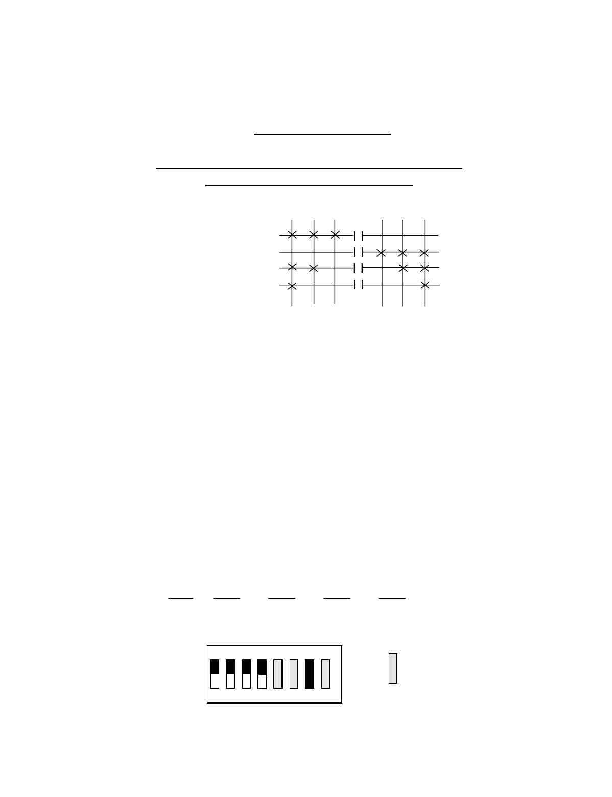
Appendix C - 10K16/24 Pendant and SLTX
Transmitter Programming (Continued)
C-7
TABLE 1(a)
Crane Control Type Selection: 10K16 TYPE 0 PROGRAMMING
____________________________________________________________________________________________________
STANDARD CONFIGURATION: ALL MOTIONS
(HOIST, TROLLEY and BRIDGE)
OUTPUT DEFINITIONS
A4-A1 BRIDGE B4-B1 HOIST B8-B5 TROLLEY
A4 EAST B4 UP B8 NORTH
A3 WEST B3 DOWN B7 SOUTH
A2 2ND SPEED B2 2ND SPEED B6 2ND SPEED
A1 3RD SPEED B1 3RD SPEED B5 3RD SPEED
INDEPENDENT OUTPUTS
A8 AUX 4 (ALARM) *C8 AUX 6 *C4 MULTIBOX 4
A7 AUX 3 (LATCHABLE S2-6) *C7 AUX 5 *C3 MULTIBOX 3
A6 AUX 2 (LATCHABLE S2-7) *C2 MULTIBOX 2
A5 AUX 1 (LATCHABLE S2-8) *C1 MULTIBOX 1
*NOTE: ON OPTIONAL OUTPUT BOARD
Transmitter Switch Select: Switch settings Sw4-5 to Sw4-8 are defined as follows:
SWITCH SETTINGS TYPE Sw4-8 Sw4-7 Sw4-6 Sw4-5
0 OFF OFF OFF OFF
OUTPUTS
A4 B4 B8
A3 B3 B7
A2 B2 B6
A1 B1 B5
3RD 2ND 1ST
DIR 1 DIR 2
1ST 2ND 3RD
OFF
ON
Sw4
For these switch
positions see the
beginning of this
section.
18234567
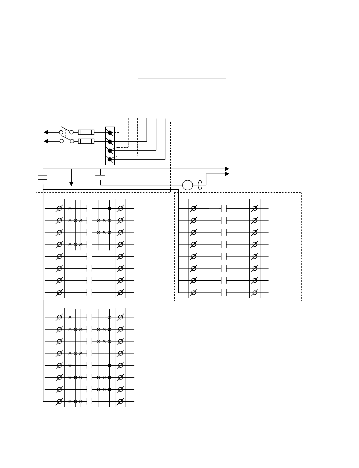
Appendix C - 10K16/24 Pendant and SLTX
Transmitter Programming (Continued)
C-8
TABLE 1(b)
Crane Control Type Selection: 10K16 TYPE 1 WIRING DIAGRAM
____________________________________________________________________________________________________
2-SPEED with DIRECTIONAL CONTROL: ALL MOTIONS
CJ3
1
2
3
4
5
6
7
8
CJ2
1
2
3
4
5
6
7
8
K1
K2
K3
K4
K5
K6
K7
K8
OPTIONAL
MULTIBOX 1
MULTIBOX 2
MULTIBOX 3
MULTIBOX 4
**AUX 5
**AUX 6
•
•
•
•
•
•
•
BJ3
1
2
3
4
5
6
7
8
BJ2
1
2
3
4
5
6
7
8
K1
K2
K3
K4
K5
K6
K7
K8
3 2 1 1 2 3
HOIST
3
RD
SPD
HOIST
UP/DOWN
HOIST
DOWN
HOIST
UP
TROLLEY
3
RD
SPD
TROLLEY
NORTH/SOUTH
TROLLEY
SOUTH
TROLLEY
NORTH
•
•
•
•
•
•
AJ3
1
2
3
4
5
6
7
8
AJ2
1
2
3
4
5
6
7
8
K1
K2
K3
K4
K5
K6
K7
K8
3 2 1 1 2 3
BRIDGE
3
RD
SPD
BRIDGE
EAST/WEST
BRIDGE
WEST
BRIDGE
EAST
AUX 1
AUX 2
AUX 3
AUX 4
(*ALARM)
•
•
•
•
•
•
•
•
*NOTE:
If it is necessary to operate the Alarm
Function during E-Stop condition, wire the input to the
alarm relay “AJ3-8” for the alarm function to the
control power hot side (relay “K1” (MR) on P/S Board
de-energized).
Telemotive receiver output boards
(E10112-X).
Multibox outputs available with factory
installed Multibox option only.
All connections to outputs AJ2, BJ2 and
CJ2 are to contactors, with proper arc
suppressors across them, controlling the
appropriate listed function to the right.
** AUX 5 and 6 available with or
without Multibox enabled.
240 VAC 120 VAC
SW1
ON/OFF
TO POWER
TRANSFORMER
E10171-X
P/S BOARD
MAIN LINE
CONTACTOR
TO
CONTROL
POWER
MLC
HOT
RET
(2)
K1 (MR)
(4)
•
•
•
*
See Note
•
240
120
FUSE J1
N
GND
(6)
K1 (MR)
(8)
•
•
•
•

Appendix C - 10K16/24 Pendant and SLTX
Transmitter Programming (Continued)
C-9
TABLE 1(b)
Crane Control Type Selection: 10K16 TYPE 1 PROGRAMMING
____________________________________________________________________________________________________
2-SPEED with DIRECTIONAL CONTROL: ALL MOTIONS
OUTPUT DEFINITIONS
A4-A1 BRIDGE B4-B1 HOIST B8-B5 TROLLEY
A4 EAST B4 UP B8 NORTH
A3 WEST B3 DOWN B7 SOUTH
A2 EAST/WEST B2 UP/DOWN B6 NORTH/SOUTH
A1 3RD SPEED B1 3RD SPEED B5 3RD SPEED
INDEPENDENT OUTPUTS
A8 AUX 4 (ALARM) *C8 AUX 6 *C4 MULTIBOX 4
A7 AUX 3 (LATCHABLE S2-6) *C7 AUX 5 *C3 MULTIBOX 3
A6 AUX 2 (LATCHABLE S2-7) *C2 MULTIBOX 2
A5 AUX 1 (LATCHABLE S2-8) *C1 MULTIBOX 1
*NOTE: ON OPTIONAL OUTPUT BOARD
Transmitter Switch Select: Switch settings Sw4-5 to Sw4-8 are defined as follows:
SWITCH SETTINGS: TYPE Sw4-8 Sw4-7 Sw4-6 Sw4-5
1 OFF OFF OFF ON
OUTPUTS
A4 B4 B8
A3 B3 B7
A2 B2 B6
A1 B1 B5
DIR 1 DIR 2
1ST 2ND 3RD
3RD 2ND 1ST
OFF
ON
Sw4
For these switch
positions see the
beginning of this
section.
18234567
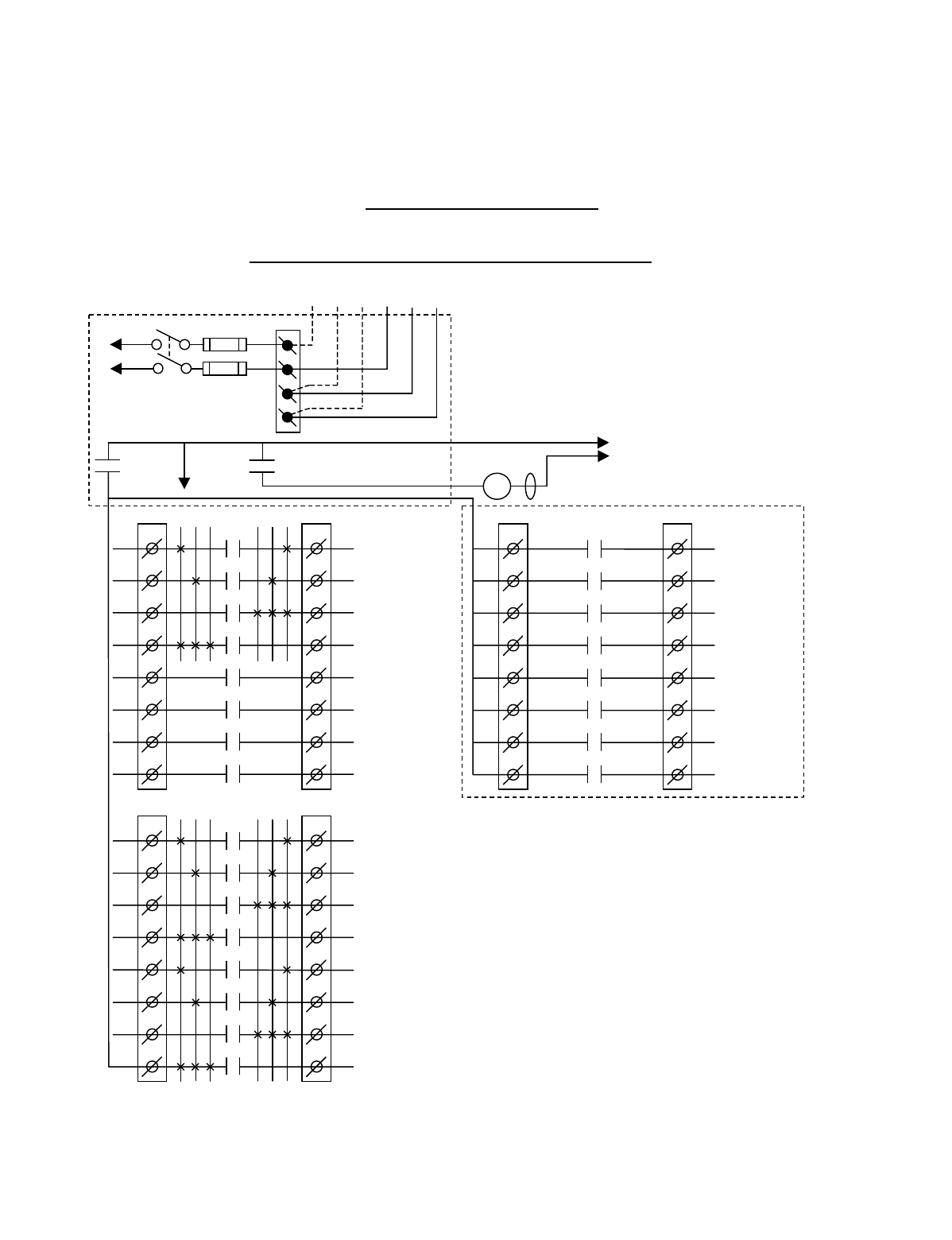
Appendix C - 10K16/24 Pendant and SLTX
Transmitter Programming (Continued)
C-10
TABLE 1(c)
Crane Control Type Selection: 10K16 TYPE 2 WIRING DIAGRAM
____________________________________________________________________________________________________
2-SPEED, 2-WINDINGS: ALL MOTIONS
CJ3
1
2
3
4
5
6
7
8
CJ2
1
2
3
4
5
6
7
8
K1
K2
K3
K4
K5
K6
K7
K8
OPTIONAL
MULTIBOX 1
MULTIBOX 2
MULTIBOX 3
MULTIBOX 4
**AUX 5
**AUX 6
•
•
•
•
•
•
•
BJ3
1
2
3
4
5
6
7
8
BJ2
1
2
3
4
5
6
7
8
K1
K2
K3
K4
K5
K6
K7
K8
3 2 1 1 2 3
HOIST
HIGH SPD
HOIST
LOW SPD
HOIST
DOWN
HOIST
UP
TROLLEY
HIGH SPD
TROLLEY
LOW SPD
TROLLEY
NORTH
TROLLEY
SOUTH
•
•
•
•
•
•
AJ3
1
2
3
4
5
6
7
8
AJ2
1
2
3
4
5
6
7
8
K1
K2
K3
K4
K5
K6
K7
K8
3 2 1 1 2 3
BRIDGE
HIGH SPD
BRIDGE
LOW SPD
BRIDGE
WEST
BRIDGE
EAST
AUX 1
AUX 2
AUX 3
AUX 4
(*ALARM)
•
•
•
•
•
•
•
•
*NOTE: If it is necessary to operate the Alarm
Function during E-Stop condition, wire the input to the
alarm relay “AJ3-8” for the alarm function to the
control power hot side (relay “K1” (MR) on P/S Board
de-energized).
Telemotive receiver output boards
(E10112-X).
Multibox outputs available with factory
installed Multibox option only.
option only.
All connections to outputs AJ2, BJ2 and
CJ2 are to contactors, with proper arc
suppressors across them, controlling the
appropriate listed function to the right.
** AUX 5 and 6 available with or
without Multibox enabled.
240 VAC 120 VAC
SW1
ON/OFF
TO POWER
TRANSFORMER E10171-X
P/S BOARD
MAIN LINE
CONTACTOR
TO
CONTROL
POWER
MLC
HOT
RET
(2)
K1 (MR)
(4)
•
•
• *See Note
•
240
120
FUSE J1
N
GND
(6)
K1 (MR)
(8)
•
•
•
•
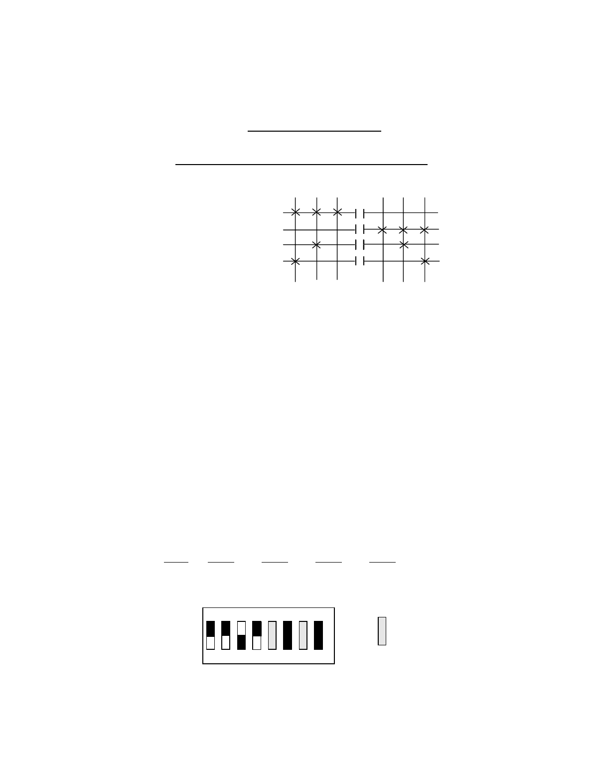
Appendix C - 10K16/24 Pendant and SLTX
Transmitter Programming (Continued)
C-11
TABLE 1(c)
Crane Control Type Selection: 10K16 TYPE 2 PROGRAMMING
____________________________________________________________________________________________________
2-SPEED, 2-WINDINGS: ALL MOTIONS
OUTPUT DEFINITIONS
A4-A1 BRIDGE B4-B1 HOIST B8-B5 TROLLEY
A4 EAST B4 UP B8 SOUTH
A3 WEST B3 DOWN B7 NORTH
A2 LOW SPEED B2 LOW SPEED B6 LOW SPEED
A1 HIGH SPEED B1 HIGH SPEED B5 HIGH SPEED
INDEPENDENT OUTPUTS
A8 AUX 4 (ALARM) *C8 AUX 6 *C4 MULTIBOX 4
A7 AUX 3 (LATCHABLE S2-6) *C7 AUX 5 *C3 MULTIBOX 3
A6 AUX 2 (LATCHABLE S2-7) *C2 MULTIBOX 2
A5 AUX 1 (LATCHABLE S2-8) *C1 MULTIBOX 1
*NOTE: ON OPTIONAL OUTPUT BOARD
Transmitter Switch Select: Switch settings Sw4-5 to Sw4-8 are defined as follows:
SWITCH SETTINGS: TYPE Sw4-8 Sw4-7 Sw4-6 Sw4-5
2 OFF OFF ON OFF
OUTPUTS
A4 B4 B8
A3 B3 B7
A2 B2 B6
A1 B1 B5
DIR 1 DIR 2
1ST 2ND 3RD
3RD 2ND 1ST
OFF
ON
Sw4
For these switch
positions see the
beginning of this
section.
18234567
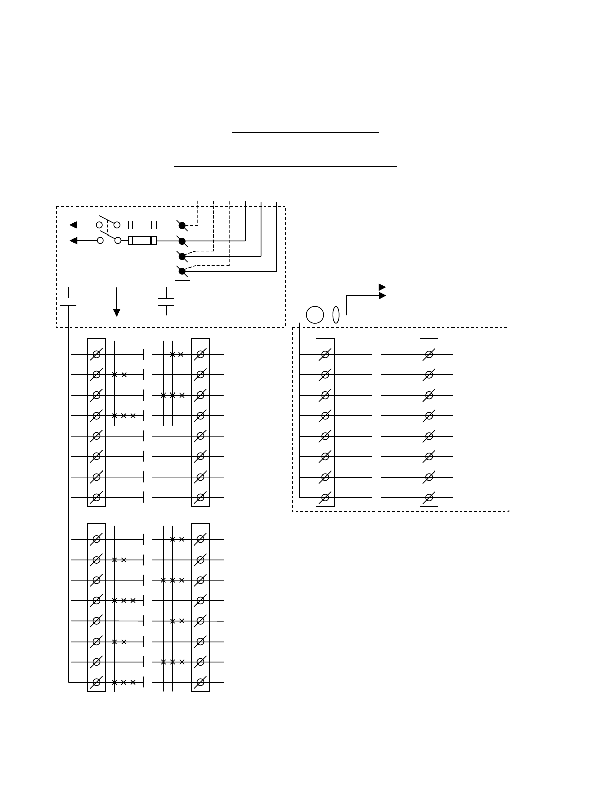
Appendix C - 10K16/24 Pendant and SLTX
Transmitter Programming (Continued)
C-12
TABLE 1(d)
Crane Control Type Selection: 10K16 TYPE 3 WIRING DIAGRAM
____________________________________________________________________________________________________
ACCO CONTROLS: ALL MOTIONS
CJ3
1
2
3
4
5
6
7
8
CJ2
1
2
3
4
5
6
7
8
K1
K2
K3
K4
K5
K6
K7
K8
OPTIONAL
MULTIBOX 1
MULTIBOX 2
MULTIBOX 3
MULTIBOX 4
**AUX 5
**AUX 6
•
•
•
•
•
•
•
BJ3
1
2
3
4
5
6
7
8
BJ2
1
2
3
4
5
6
7
8
K1
K2
K3
K4
K5
K6
K7
K8
3 2 1 1 2 3
HOIST
DOWN 2ND SPD
HOIST
UP 2ND SPD
HOIST
DOWN
HOIST
UP
TROLLEY
SOUTH 2ND SPD
TROLLEY
NORTH 2ND SPD
TROLLEY
SOUTH
TROLLEY
NORTH
•
•
•
•
•
•
AJ3
1
2
3
4
5
6
7
8
AJ2
1
2
3
4
5
6
7
8
K1
K2
K3
K4
K5
K6
K7
K8
3 2 1 1 2 3
BRIDGE
WEST 2ND SPD
BRIDGE
EAST 2ND SPD
BRIDGE
WEST
BRIDGE
EAST
AUX 1
AUX 2
AUX 3
AUX 4
(*ALARM)
•
•
•
•
•
•
•
•
*NOTE: If it is necessary to operate the Alarm
Function during E-Stop condition, wire the input to the
alarm relay “AJ3-8” for the alarm function to the
control power hot side (relay “K1” (MR) on P/S Board
de-energized).
Telemotive receiver output boards
(E10112-X).
Multibox outputs available with factory
installed Multibox option only.
option only.
All connections to outputs AJ2, BJ2 and
CJ2 are to contactors, with proper arc
suppressors across them, controlling the
appropriate listed function to the right.
** AUX 5 and 6 available with or
without Multibox enabled.
240 VAC 120 VAC
SW1
ON/OFF
TO POWER
TRANSFORMER E10171-X
P/S BOARD
MAIN LINE
CONTACTOR
TO
CONTROL
POWER
MLC
HOT
RET
(2)
K1 (MR)
(4)
•
•
• *See Note
•
240
120
FUSE J1
N
GND
(6)
K1 (MR)
(8)
•
•
•
•
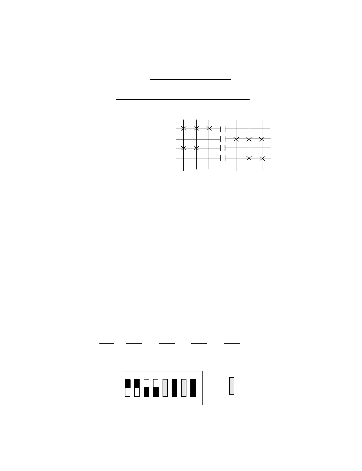
Appendix C - 10K16/24 Pendant and SLTX
Transmitter Programming (Continued)
C-13
TABLE 1(d)
Crane Control Type Selection: 10K16 TYPE 3 PROGRAMMING
____________________________________________________________________________________________________
ACCO CONTROLS: ALL MOTIONS
OUTPUT DEFINITIONS
A4-A1 BRIDGE B4-B1 HOIST B8-B5 TROLLEY
A4 EAST B4 UP B8 NORTH
A3 WEST B3 DOWN B7 SOUTH
A2 EAST 2ND SPEED B2 UP 2ND SPEED B6 NORTH 2ND SPEED
A1 WEST 2ND SPEED B1 DOWN 2ND SPEED B5 SOUTH 2ND SPEED
INDEPENDENT OUTPUTS
A8 AUX 4 (ALARM) *C8 AUX 6 *C4 MULTIBOX 4
A7 AUX 3 (LATCHABLE S2-6) *C7 AUX 5 *C3 MULTIBOX 3
A6 AUX 2 (LATCHABLE S2-7) *C2 MULTIBOX 2
A5 AUX 1 (LATCHABLE S2-8) *C1 MULTIBOX 1
*NOTE: ON OPTIONAL OUTPUT BOARD
Transmitter Switch Select: Switch settings Sw4-5 to Sw4-8 are defined as follows:
SWITCH SETTINGS: TYPE Sw4-8 Sw4-7 Sw4-6 Sw4-5
3OFF OFF ON ON
OUTPUTS
A4 B4 B8
A3 B3 B7
A2 B2 B6
A1 B1 B5
DIR 1 DIR 2
1ST 2ND 3RD
3RD 2ND 1ST
OFF
ON
Sw4
For these switch
positions see the
beginning of this
section.
18234567

Appendix C - 10K16/24 Pendant and SLTX
Transmitter Programming (Continued)
C-14
TABLE 1(e)
Crane Control Type Selection: 10K16 TYPE 4 WIRING DIAGRAM
____________________________________________________________________________________________________
DEMAG: 2-SPEED, 2-WINDINGS for HOIST:
STANDARD BRIDGE and TROLLEY
CJ3
1
2
3
4
5
6
7
8
CJ2
1
2
3
4
5
6
7
8
K1
K2
K3
K4
K5
K6
K7
K8
OPTIONAL
MULTIBOX 1
MULTIBOX 2
MULTIBOX 3
MULTIBOX 4
**AUX 5
**AUX 6
•
•
•
•
•
•
•
BJ3
1
2
3
4
5
6
7
8
BJ2
1
2
3
4
5
6
7
8
K1
K2
K3
K4
K5
K6
K7
K8
3 2 1 1 2 3
HOIST
DOWN 2ND SPD
HOIST
UP 2ND SPD
HOIST
DOWN
HOIST
UP
TROLLEY
3RD SPD
TROLLEY
2ND SPD
TROLLEY
SOUTH
TROLLEY
NORTH
•
•
•
•
•
•
AJ3
1
2
3
4
5
6
7
8
AJ2
1
2
3
4
5
6
7
8
K1
K2
K3
K4
K5
K6
K7
K8
3 2 1 1 2 3
BRIDGE
3RD SPD
BRIDGE
2ND SPD
BRIDGE
WEST
BRIDGE
EAST
AUX 1
AUX 2
AUX 3
AUX 4
(*ALARM)
•
•
•
•
•
•
•
•
*NOTE: If it is necessary to operate the Alarm
Function during E-Stop condition, wire the input to the
alarm relay “AJ3-8” for the alarm function to the
control power hot side (relay “K1” (MR) on P/S Board
de-energized).
Telemotive receiver output boards
(E10112-X).
Multibox outputs available with factory
installed Multibox option only.
option only.
All connections to outputs AJ2, BJ2 and
CJ2 are to contactors, with proper arc
suppressors across them, controlling the
appropriate listed function to the right.
** AUX 5 and 6 available with or
without Multibox enabled.
240 VAC 120 VAC
SW1
ON/OFF
TO POWER
TRANSFORMER E10171-X
P/S BOARD
MAIN LINE
CONTACTOR
TO
CONTROL
POWER
MLC
HOT
RET
(2)
K1 (MR)
(4)
•
•
• *See Note
•
240
120
FUSE J1
N
GND
(6)
K1 (MR)
(8)
•
•
•
•
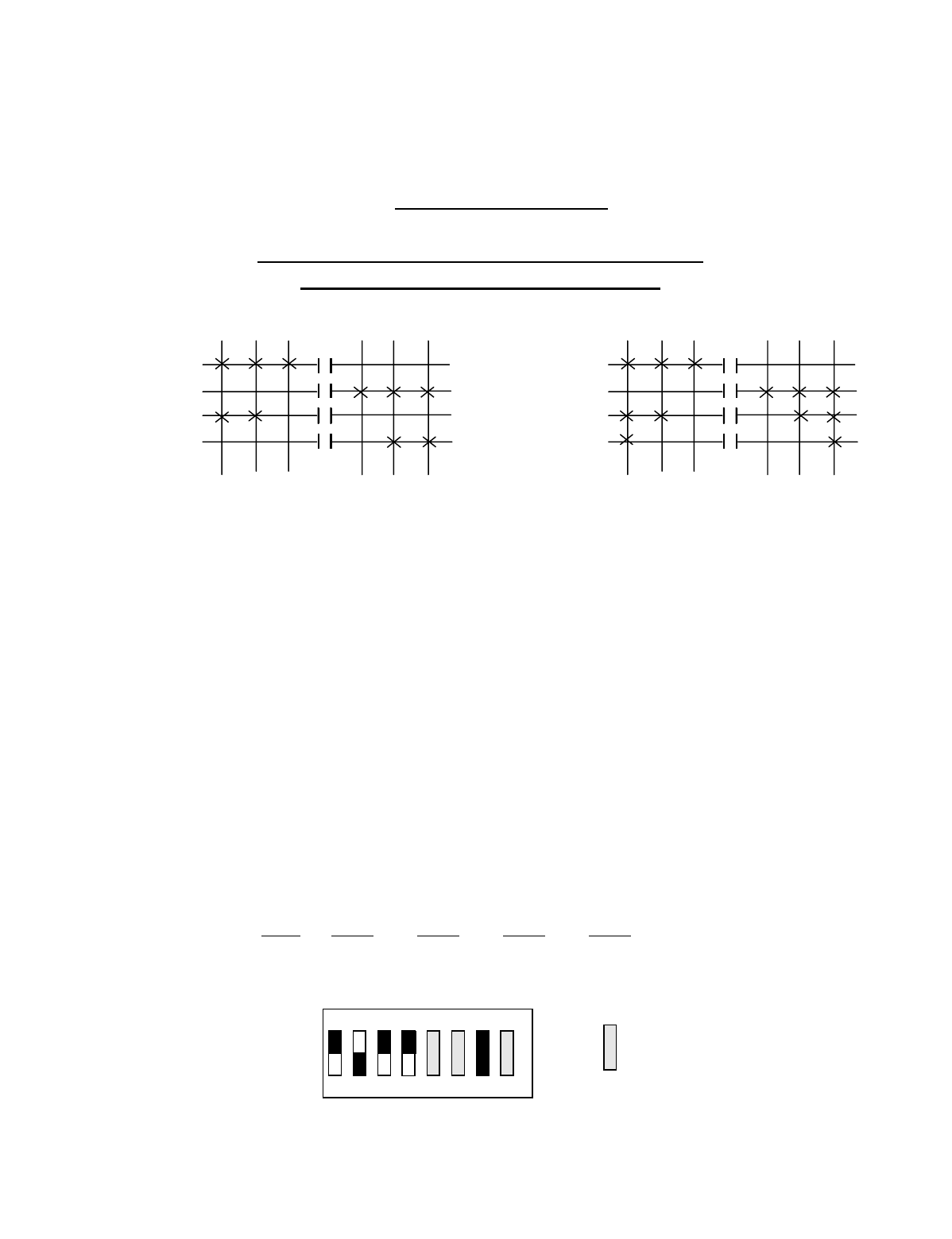
Appendix C - 10K16/24 Pendant and SLTX
Transmitter Programming (Continued)
C-15
TABLE 1(e)
Crane Control Type Selection: 10K16 TYPE 4 PROGRAMMING
____________________________________________________________________________________________________
DEMAG: 2-SPEED, 2-WINDINGS for HOIST:
STANDARD BRIDGE and TROLLEY
OUTPUT DEFINITIONS
A4-A1 BRIDGE B4-B1 HOIST B8-B5 TROLLEY
A4 EAST B4 UP B8 NORTH
A3 WEST B3 DOWN B7 SOUTH
A2 2ND SPEED B2 UP 2ND SPEED B6 2ND SPEED
A1 3RD SPEED B1 DOWN 2ND SPEED B5 3RD SPEED
INDEPENDENT OUTPUTS
A8 AUX 4 (ALARM) *C8 AUX 6 *C4 MULTIBOX 4
A7 AUX 3 (LATCHABLE S2-6) *C7 AUX 5 *C3 MULTIBOX 3
A6 AUX 2 (LATCHABLE S2-7) *C2 MULTIBOX 2
A5 AUX 1 (LATCHABLE S2-8) *C1 MULTIBOX 1
*NOTE: ON OPTIONAL OUTPUT BOARD
Transmitter Switch Select: Switch settings Sw4-5 to Sw4-8 are defined as follows:
SWITCH SETTINGS: TYPE Sw4-8 Sw4-7 Sw4-6 Sw4-5
4 OFF ON OFF OFF
OUTPUTS
B4
B3
B2
B1
DIR 1 DIR 2
1ST 2ND 3RD
OUTPUTS
A4 B8
A3 B7
A2 B6
A1 B5
DIR 1 DIR 2
1ST 2ND 3RD
3RD 2ND 1ST 3RD 2ND 1ST
OFF
ON
Sw4
For these switch
positions see the
beginning of this
section.
18234567
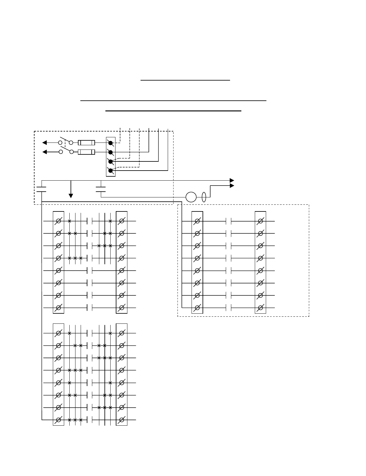
Appendix C - 10K16/24 Pendant and SLTX
Transmitter Programming (Continued)
C-16
TABLE 1(f)
Crane Control Type Selection: 10K16 TYPE 5 WIRING DIAGRAM
____________________________________________________________________________________________________
P&H HOIST: 2-SPEED, 2-WINDINGS for HOIST:
STANDARD BRIDGE and TROLLEY
CJ3
1
2
3
4
5
6
7
8
CJ2
1
2
3
4
5
6
7
8
K1
K2
K3
K4
K5
K6
K7
K8
OPTIONAL
MULTIBOX 1
MULTIBOX 2
MULTIBOX 3
MULTIBOX 4
**AUX 5
**AUX 6
•
•
•
•
•
•
•
BJ3
1
2
3
4
5
6
7
8
BJ2
1
2
3
4
5
6
7
8
K1
K2
K3
K4
K5
K6
K7
K8
3 2 1 1 2 3
HOIST
DOWN 2ND SPD
HOIST
UP 2ND SPD
HOIST
DOWN
HOIST
UP
TROLLEY
3RD SPD
TROLLEY
2ND SPD
TROLLEY
SOUTH
TROLLEY
NORTH
•
•
•
•
•
•
AJ3
1
2
3
4
5
6
7
8
AJ2
1
2
3
4
5
6
7
8
K1
K2
K3
K4
K5
K6
K7
K8
3 2 1 1 2 3
BRIDGE
3RD SPD
BRIDGE
2ND SPD
BRIDGE
WEST
BRIDGE
EAST
AUX 1
AUX 2
AUX 3
AUX 4
(*ALARM)
•
•
•
•
•
•
•
•
*NOTE: If it is necessary to operate the Alarm
Function during E-Stop condition, wire the input to the
alarm relay “AJ3-8” for the alarm function to the
control power hot side (relay “K1” (MR) on P/S Board
de-energized).
Telemotive receiver output boards
(E10112-X).
Multibox outputs available with factory
installed Multibox option only.
option only.
All connections to outputs AJ2, BJ2 and
CJ2 are to contactors, with proper arc
suppressors across them, controlling the
appropriate listed function to the right.
** AUX 5 and 6 available with or
without Multibox enabled.
240 VAC 120 VAC
SW1
ON/OFF
TO POWER
TRANSFORMER E10171-X
P/S BOARD
MAIN LINE
CONTACTOR
TO
CONTROL
POWER
MLC
HOT
RET
(2)
K1 (MR)
(4)
•
•
• *See Note
•
240
120
FUSE J1
N
GND
(6)
K1 (MR)
(8)
•
•
•
•
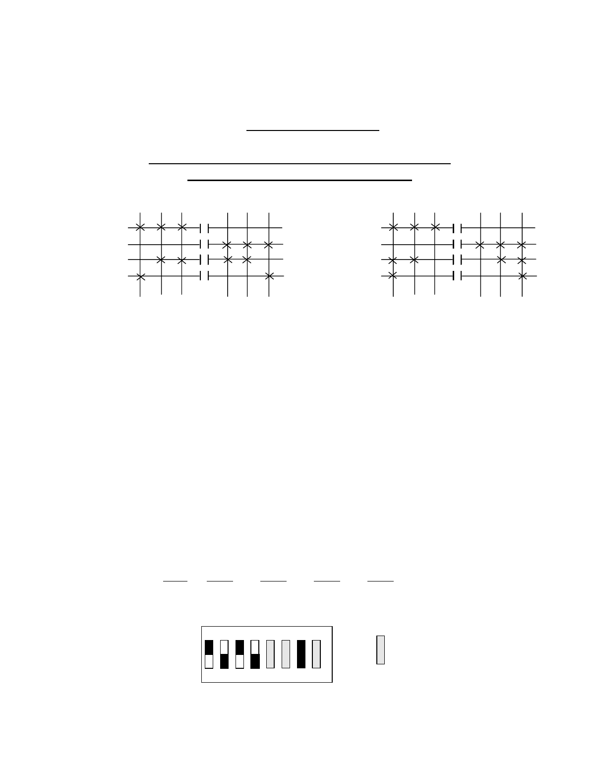
Appendix C - 10K16/24 Pendant and SLTX
Transmitter Programming (Continued)
C-17
TABLE 1(f)
Crane Control Type Selection: 10K16 TYPE 5 PROGRAMMING
____________________________________________________________________________________________________
P&H HOIST: 2-SPEED, 2-WINDINGS for HOIST:
STANDARD BRIDGE and TROLLEY
OUTPUT DEFINITIONS
A4-A1 BRIDGE B4-B1 HOIST B8-B5 TROLLEY
A4 EAST B4 UP B8 NORTH
A3 WEST B3 DOWN B7 SOUTH
A2 2ND SPEED B2 UP 2ND SPEED B6 2ND SPEED
A1 3RD SPEED B1 DOWN 2ND SPEED B5 3RD SPEED
INDEPENDENT OUTPUTS
A8 AUX 4 (ALARM) *C8 AUX 6 *C4 MULTIBOX 4
A7 AUX 3 (LATCHABLE S2-6) *C7 AUX 5 *C3 MULTIBOX 3
A6 AUX 2 (LATCHABLE S2-7) *C2 MULTIBOX 2
A5 AUX 1 (LATCHABLE S2-8) *C1 MULTIBOX 1
*NOTE: ON OPTIONAL OUTPUT BOARD
Transmitter Switch Select: Switch settings Sw4-5 to Sw4-8 are defined as follows:
SWITCH SETTINGS: TYPE Sw4-8 Sw4-7 Sw4-6 Sw4-5
5OFF ON OFF ON
OUTPUTS
B4
B3
B2
B1
DIR 1 DIR 2
1ST 2ND 3RD
OUTPUTS
A4 B8
A3 B7
A2 B6
A1 B5
DIR 1 DIR 2
1ST 2ND 3RD
3RD 2ND 1
S
T3RD 2ND 1ST
OFF
ON
Sw4
For these switch
positions see the
beginning of this
section.
18234567
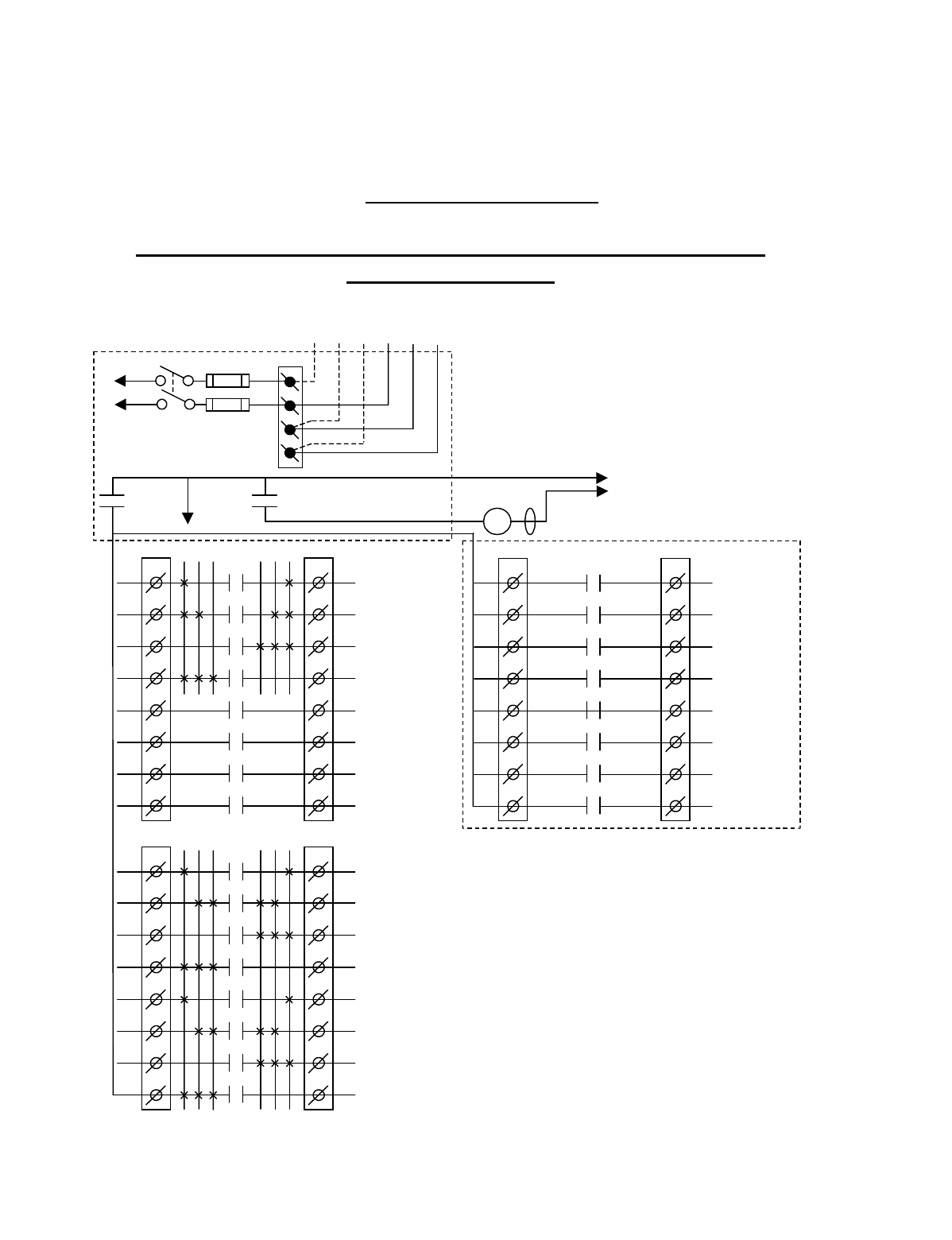
Appendix C - 10K16/24 Pendant and SLTX
Transmitter Programming (Continued)
C-18
TABLE 1(g)
Crane Control Type Selection: 10K16 TYPE 6 WIRING DIAGRAM
____________________________________________________________________________________________________
P&H HOIST: 2-SPEED, 2-WINDINGS for HOIST and TROLLEY:
STANDARD BRIDGE
CJ3
1
2
3
4
5
6
7
8
CJ2
1
2
3
4
5
6
7
8
K1
K2
K3
K4
K5
K6
K7
K8
OPTIONAL
MULTIBOX 1
MULTIBOX 2
MULTIBOX 3
MULTIBOX 4
**AUX 5
**AUX 6
•
•
•
•
•
•
•
K1
K2
K3
K4
K5
K6
K7
K8
3 2 1 1 2 3
•
•
•
•
•
•
AJ3
1
2
3
4
5
6
7
8
AJ2
1
2
3
4
5
6
7
8
K1
K2
K3
K4
K5
K6
K7
K8
3 2 1 1 2 3
BRIDGE
3
RD
SPD
BRIDGE
2
ND
SPD
BRIDGE
WEST
BRIDGE
EAST
AUX 1
AUX 2
AUX 3
AUX 4
(*ALARM)
•
•
•
•
•
•
•
•
*NOTE:
If it is necessary to operate the Alarm
Function during E-Stop condition, wire the input to the
alarm relay “AJ3-8” for the alarm function to the
control power hot side (relay “K1” (MR) on P/S Board
de-energized).
Telemotive receiver output boards
(E10112-X).
Multibox outputs available with factory
installed Multibox option only. option
only.
All connections to outputs AJ2, BJ2 and
CJ2 are to contactors, with proper arc
suppressors across them, controlling the
appropriate listed function to the right.
** AUX 5 and 6 available with or
without Multibox enabled.
240 VAC 120 VAC
SW1
ON/OFF
TO POWER
TRANSFORMER
E10171-X
P/S BOARD
MAIN LINE
CONTACTOR
TO
CONTROL
POWER
MLC
HOT
RET
(2)
K1 (MR)
(4)
•
•
•
*
See Note
•
240
120
FUSE J1
N
GND
(6)
K1 (MR)
(8)
•
•
•
•
BJ3
1
2
3
4
5
6
7
8
BJ2
1
2
3
4
5
6
7
8
HOIST HIGH
SPEED
HOIST LOW
SPEED
HOIST
DOWN
HOIST
UP
TROLLEY
HIGH SPEED
TROLLEY
LOW SPEED
TROLLEY
SOUTH
TROLLEY
NORTH
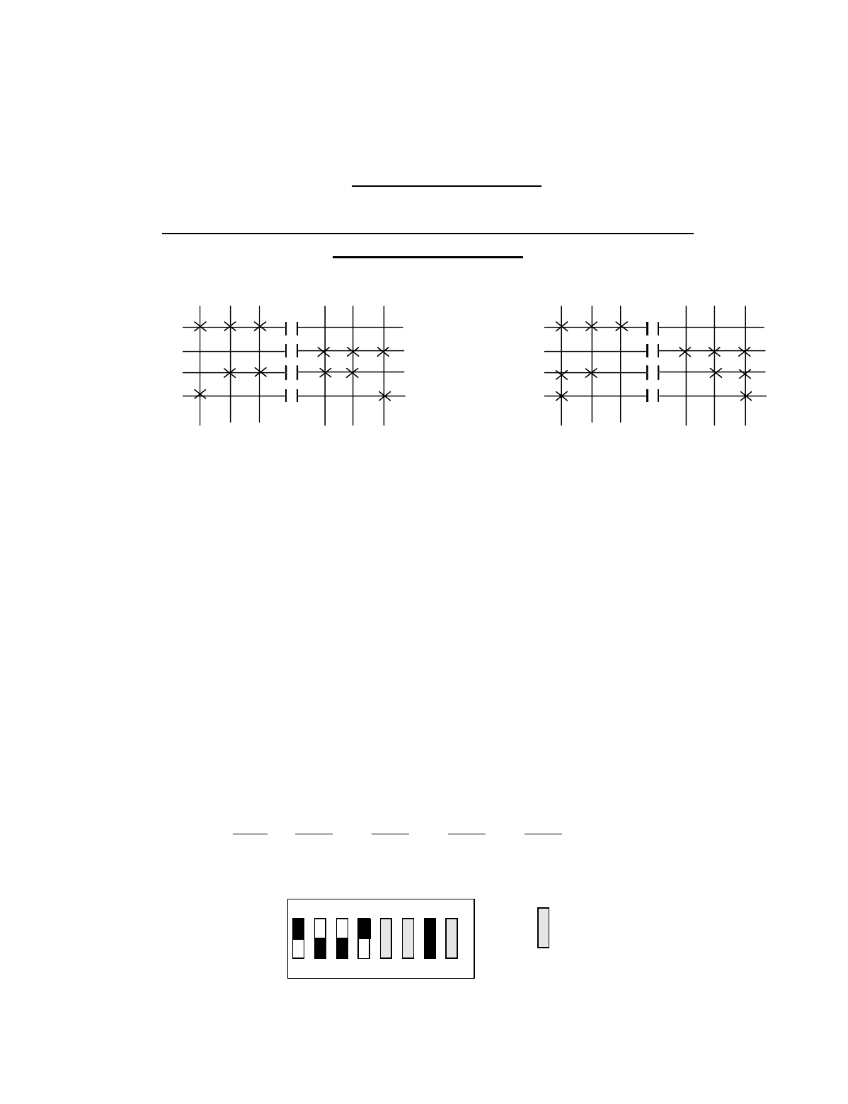
Appendix C - 10K16/24 Pendant and SLTX
Transmitter Programming (Continued)
C-19
TABLE 1(g)
Crane Control Type Selection: 10K16 TYPE 6 PROGRAMMING
____________________________________________________________________________________________________
P&H HOIST: 2-SPEED, 2-WINDINGS HOIST and TROLLEY:
STANDARD BRIDGE
OUTPUT DEFINITIONS
A4-A1 BRIDGE B4-B1 HOIST B8-B5 TROLLEY
A4 EAST B4 UP B8 NORTH
A3 WEST B3 DOWN B7 SOUTH
A2 2ND SPEED B2 LOW SPEED B6 LOW SPEED
A1 3RD SPEED B1 HIGH SPEED B5 HIGH SPEED
INDEPENDENT OUTPUTS
A8 AUX 4 (ALARM) *C8 AUX 6 *C4 MULTIBOX 4
A7 AUX 3 (LATCHABLE S2-6) *C7 AUX 5 *C3 MULTIBOX 3
A6 AUX 2 (LATCHABLE S2-7) *C2 MULTIBOX 2
A5 AUX 1 (LATCHABLE S2-8) *C1 MULTIBOX 1
*NOTE: ON OPTIONAL OUTPUT BOARD
Transmitter Switch Select: Switch settings Sw4-5 to Sw4-8 are defined as follows:
SWITCH SETTINGS: TYPE Sw4-8 Sw4-7 Sw4-6 Sw4-5
6 OFF ON ON OFF
OUTPUTS
B4 B8
B3 B7
B2 B6
B1 B5
DIR 1 DIR 2
1ST 2ND 3RD
OUTPUTS
A4
A3
A2
A1
DIR 1 DIR 2
1ST 2ND 3RD
3RD 2ND 1
S
T3RD 2ND 1ST
OFF
ON
Sw4
For these switch
positions see the
beginning of this
section.
18234567

Appendix C - 10K16/24 Pendant and SLTX
Transmitter Programming (Continued)
C-20
This Page Intentionally Left Blank
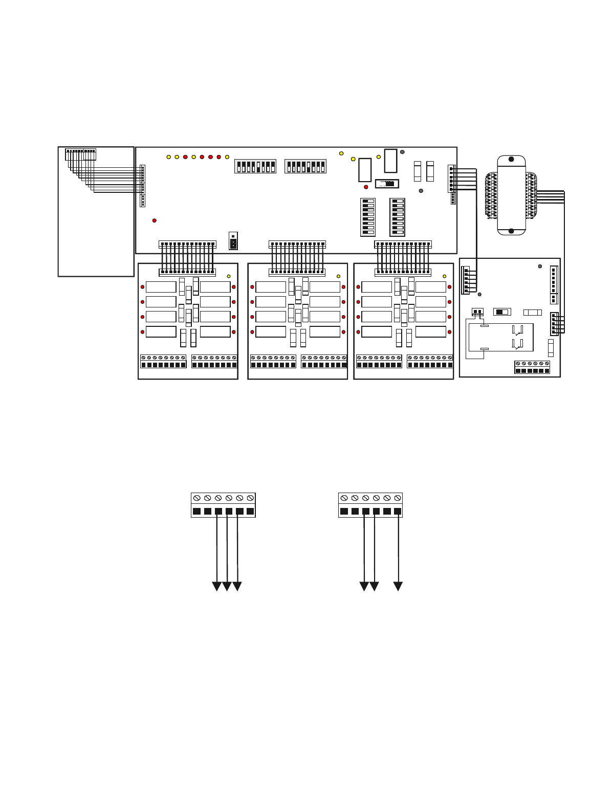
Appendix C - 10K16/24 Pendant and SLTX
Transmitter Programming (Continued)
C-21
Figure C-3. 10K24 Wiring Layout
J1 Power Supply
Board
NGNDN120 240120
Ground
Neutral
120VAC
NGNDN120 240120
Ground
240VAC B
240VAC A
220 VAC Wiring110 VAC Wiring
J2
123456 78 12345678
J3
DS9
DS1 DS2 DS3 DS4
K1
K2
K3
K4
K5
K6
K7
K8
F1
F2
F3
F4 F5
F6
F7
F8
DS5 DS6 DS7 DS8
J1
RELAY BOARD
J2
123456 78 12345678
J3
DS9
DS1 DS2 DS3 DS4
K1
K2
K3
K4
K5
K6
K7
K8
F1
F2
F3
F4 F5
F6
F7
F8
DS5 DS6 DS7 DS8
J1
RELAY BOARD
J5
F2
DS2
DS
1SW1
ON OFF
J2
J3 J7
POWER
SUPPLY
BOARD
RECEIVER BOARD
T
R
A
N
S
F
O
R
M
E
R
J3
J4
DS-15
DS2
K
1
S1
DS5
DS4 DS1
DS3
J7 J8 J6
87654321
87654 321
0FF 0FF
S3 S2
0FF
87654 321
S5
87654321
S4
0FF
DS-7 -8 -9 -10 -11-12 -13-14
J5
JU2
J2
J1
K
2
DS6
ON
CPU BOARD
F1
J6
J1
NGNDN120 240120
2
86
4
MASTER
CONTROL
RELAY
(MCR)
K1
OUTPUTS INPUTS OUTPUTS INPUTS OUTPUTS INPUTS
Position A Position B Position C
BA
F2 F1
J2
123456 78 12345678
J3
DS9
DS1 DS2 DS3 DS4
K1
K2
K3
K4
K5
K6
K7
K8
F1
F2
F3
F4 F5
F6
F7
F8
DS5 DS6 DS7 DS8
J1
RELAY BOARD

Appendix C - 10K16/24 Pendant and SLTX
Transmitter Programming (Continued)
C-22
TABLE 2(a)
Crane Control Type Selection: 10K24 TYPE 0 WIRING DIAGRAM
____________________________________________________________________________________________________
STANDARD CONFIGURATION: ALL MOTIONS
(HOIST, TROLLEY and BRIDGE)
CJ3
1
2
3
4
5
6
7
8
CJ2
1
2
3
4
5
6
7
8
K1
K2
K3
K4
K5
K6
K7
K8
3 2 1 1 2 3
AUX HOIST
3RD SPD
AUX HOIST
2ND SPD
AUX HOIST
DOWN
AUX HOIST
UP
AUX TROLLEY
3RD SPD
AUX TROLLEY
2ND SPD
AUX TROLLEY
SOUTH
AUX TROLLEY
NORTH
•
•
•
•
•
•
•
BJ3
1
2
3
4
5
6
7
8
BJ2
1
2
3
4
5
6
7
8
K1
K2
K3
K4
K5
K6
K7
K8
3 2 1 1 2 3
HOIST
3RD SPD
HOIST
2ND SPD
HOIST
DOWN
HOIST
UP
TROLLEY
3RD SPD
TROLLEY
2ND SPD
TROLLEY
SOUTH
TROLLEY
NORTH
•
•
•
•
•
•
•
AJ3
1
2
3
4
5
6
7
8
AJ2
1
2
3
4
5
6
7
8
K1
K2
K3
K4
K5
K6
K7
K8
3 2 1 1 2 3
BRIDGE
3RD SPD
BRIDGE
2ND SPD
BRIDGE
WEST
BRIDGE
EAST
AUX 1
AUX 2
AUX 3
AUX 4
(*ALARM)
•
•
•
•
•
•
•
•
*NOTE: If it is necessary to operate the Alarm
Function during E-Stop condition, wire the input to the
alarm relay “AJ3-8” for the alarm function to the
control power hot side (relay “K1” (MR) on P/S Board
de-energized).
Telemotive receiver output boards (E10112-X).
All connections to outputs AJ2, BJ2 and CJ2 are to
contactors, with proper arc suppressors across them,
controlling the appropriate listed function to the right.
For Multibox Systems
C1 Multibox 1
C2 Multibox 2
C3 Multibox 3
C4 Multibox 4
C5–C8 Match C5-C8 above if S3-4 on the Receiver CPU
Board is turned “OFF” .
C5-C8 Match C1-C4 respectively above if S3-4 on the
Receiver CPU Board is turned “ON”.
240 VAC 120 VAC
SW1
ON/OFF
TO POWER
TRANSFORMER E10171-X
P/S BOARD
MAIN LINE
CONTACTOR
TO
CONTROL
POWER
MLC
HOT
RET
(2)
K1 (MR)
(4)
•
•
• *See Note
•
240
120
FUSE J1
N
GND
(6)
K1 (MR)
(8)
•
•
•
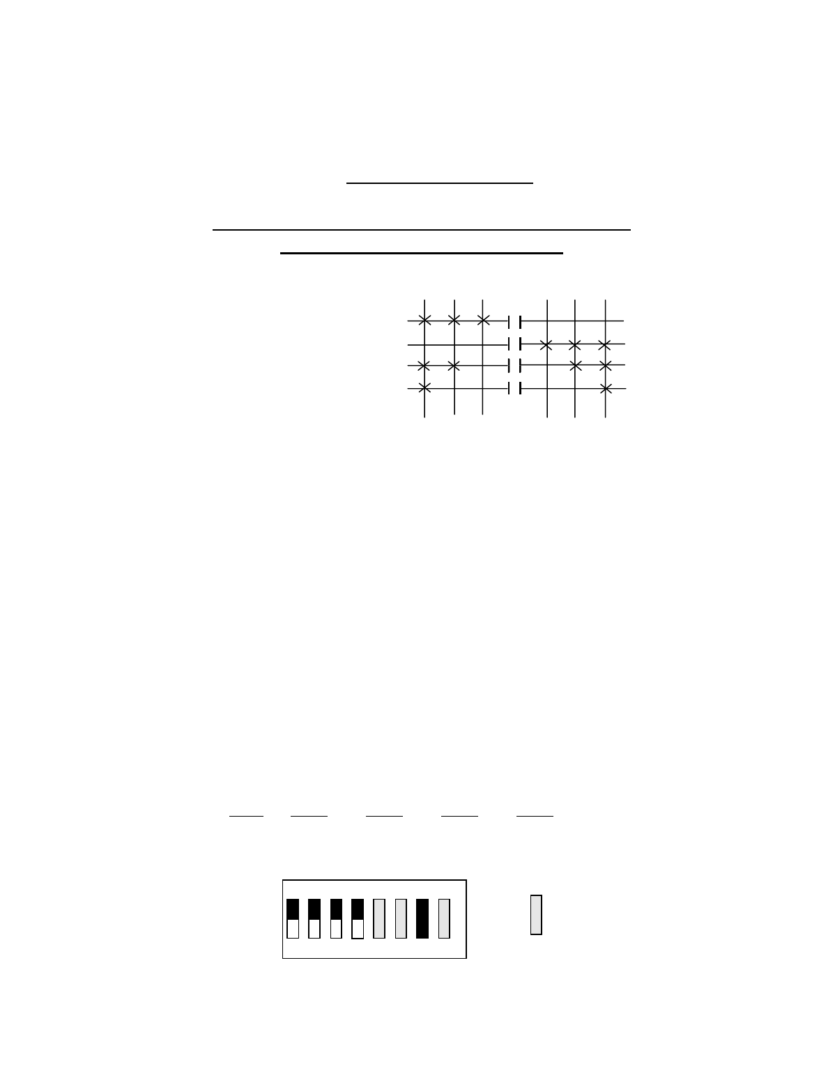
Appendix C - 10K16/24 Pendant and SLTX
Transmitter Programming (Continued)
C-23
TABLE 2(a)
Crane Control Type Selection: 10K24 TYPE 0 PROGRAMMING
____________________________________________________________________________________________________
STANDARD CONFIGURATION: ALL MOTIONS
(HOIST, TROLLEY and BRIDGE)
OUTPUT DEFINITIONS*
A4-A1 BRIDGE B4-B1 HOIST B8-B5 TROLLEY C4-C1 AUX HOIST C8-C5 AUX TROLLEY
A4 EAST B4 UP B8 NORTH C4 UP C8 NORTH
A3 WEST B3 DOWN B7 SOUTH C3 DOWN C7 SOUTH
A2 2ND SPD B2 2ND SPD B6 2ND SPD C2 2ND SPD C6 2ND SPD
A1 3RD SPD B1 3RD SPD B5 3RD SPD C1 3RD SPD C5 3RD SPD
INDEPENDENT OUTPUTS
A8 AUX 4 (ALARM)
A7 AUX 3 (LATCHABLE S2-6)
A6 AUX 2 (LATCHABLE S2-7)
A5 AUX 1 (LATCHABLE S2-8)
*For Multibox Systems read Multibox details at the beginning of this section.
Transmitter Switch Select: Switch settings Sw4-5 to Sw4-8 are defined as follows:
SWITCH SETTINGS: TYPE Sw4-8 Sw4-7 Sw4-6 Sw4-5
0 OFF OFF OFF OFF
OUTPUTS
A4 B4 B8 C4 C8
A3 B3 B7 C3 C7
A2 B2 B6 C2 C6
A1 B1 B5 C1 C5
DIR 1 DIR 2
1ST 2ND 3RD
3RD 2ND 1ST
OFF
ON
Sw4
For these switch
positions see the
beginning of this
section.
18234567
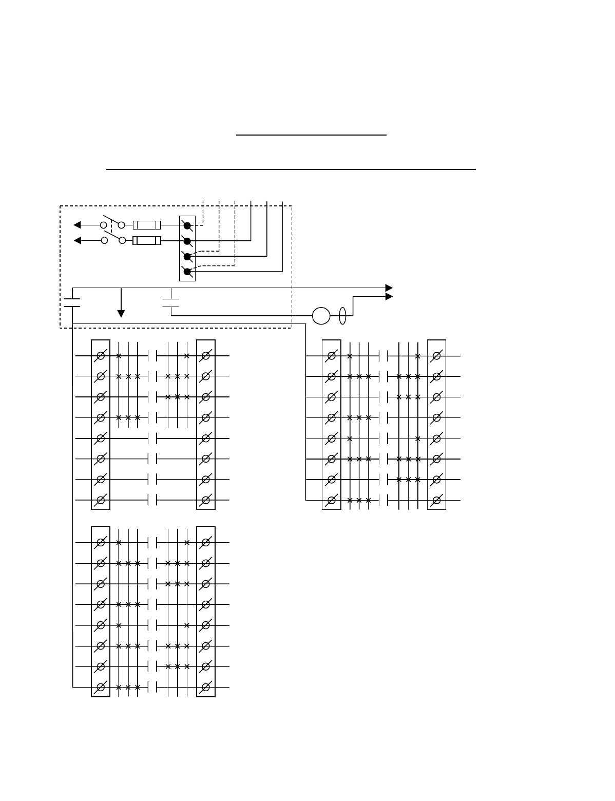
Appendix C - 10K16/24 Pendant and SLTX
Transmitter Programming (Continued)
C-24
TABLE 2(b)
Crane Control Type Selection: 10K24 TYPE 1 WIRING DIAGRAM
____________________________________________________________________________________________________
2-SPEED with DIRECTIONAL CONTROL: ALL MOTIONS
CJ3
1
2
3
4
5
6
7
8
CJ2
1
2
3
4
5
6
7
8
K1
K2
K3
K4
K5
K6
K7
K8
3 2 1 1 2 3
AUX HOIST
3
RD
SPD
AUX HOIST
UP/DOWN
AUX HOIST
DOWN
AUX HOIST
UP
AUX TROLLEY
3
RD
SPD
AUX TROLLEY
NORTH/SOUTH
AUX TROLLEY
SOUTH
AUX TROLLEY
NORTH
•
•
•
•
•
•
•
BJ3
1
2
3
4
5
6
7
8
BJ2
1
2
3
4
5
6
7
8
K1
K2
K3
K4
K5
K6
K7
K8
3 2 1 1 2 3 HOIST
3
RD
SPD
HOIST
UP/DOWN
HOIST
DOWN
HOIST
UP
TROLLEY
3
RD
SPD
TROLLEY
NORTH/SOUTH
TROLLEY
SOUTH
TROLLEY
NORTH
•
•
•
•
•
•
AJ3
1
2
3
4
5
6
7
8
AJ2
1
2
3
4
5
6
7
8
K1
K2
K3
K4
K5
K6
K7
K8
3 2 1 1 2 3
BRIDGE
3
RD
SPD
BRIDGE
EAST/WEST
BRIDGE
WEST
BRIDGE
EAST
AUX 1
AUX 2
AUX 3
AUX 4
(*ALARM)
•
•
•
•
•
•
•
•
*NOTE:
If it is necessary to operate the Alarm
Function during E-Stop condition, wire the input to the
alarm relay “AJ3-8” for the alarm function to the
control power hot side (relay “K1” (MR) on P/S Board
de-energized).
240 VAC 120 VAC
SW1
ON/OFF
TO POWER
TRANSFORMER
E10171-X
P/S BOARD
MAIN LINE
CONTACTOR
TO
CONTROL
POWER
HOT
RET
(2)
K1 (MR)
(4)
•
•
•
*
See Note
•
240
120
FUSE J1
N
GND
(6)
K1 (MR)
(8)
•
•
•
•
Telemotive receiver output boards (E10112-X).
All connections to outputs AJ2, BJ2 and CJ2 are to
contactors, with proper arc suppressors across them,
controlling the appropriate listed function to the right.
For Multibox Systems
C1 Multibox 1
C2 Multibox 2
C3 Multibox 3
C4 Multibox 4
C5–C8 Match C5-C8 above if S3-4 on the Receiver
CPU Board is turned “OFF” .
C5-C8 Match C1-C4 respectively above if S3-4 on the
Receiver CPU Board is turned “ON”.
MLC

Appendix C - 10K16/24 Pendant and SLTX
Transmitter Programming (Continued)
C-25
TABLE 2(b)
Crane Control Type Selection: 10K24 TYPE 1 PROGRAMMING
____________________________________________________________________________________________________
2-SPEED with DIRECTIONAL CONTROL: ALL MOTIONS
OUTPUT DEFINITIONS*
A4-A1 BRIDGE B4-B1 HOIST B8-B5 TROLLEY C4-C1 AUX HOIST C8-C5 AUX TROLLEY
A4 EAST B4 UP B8 NORTH C4 UP C8 NORTH
A3 WEST B3 DOWN B7 SOUTH C3 DOWN C7 SOUTH
A2 EAST/WEST B2 UP/DOWN B6 NORTH/SOUTH C2 UP/DOWN C6 NORTH/SOUTH
A1 3RD SPD B1 3RD SPD B5 3RD SPD C1 3RD SPD C5 3RD SPD
INDEPENDENT OUTPUTS
A8 AUX 4 (ALARM)
A7 AUX 3 (LATCHABLE S2-6)
A6 AUX 2 (LATCHABLE S2-7)
A5 AUX 1 (LATCHABLE S2-8)
*For Multibox Systems read Multibox details at the beginning of this section.
Transmitter Switch Select: Switch settings Sw4-5 to Sw4-8 are defined as follows:
SWITCH SETTINGS: TYPE Sw4-8 Sw4-7 Sw4-6 Sw4-5
1 OFF OFF OFF ON
OUTPUTS
A4 B4 B8 C4 C8
A3 B3 B7 C3 C7
A2 B2 B6 C2 C6
A1 B1 B5 C1 C5
DIR 1 DIR 2
1ST 2ND 3RD
3RD 2ND 1ST
OFF
ON
Sw4
For these switch
positions see the
beginning of this
section.
18234567
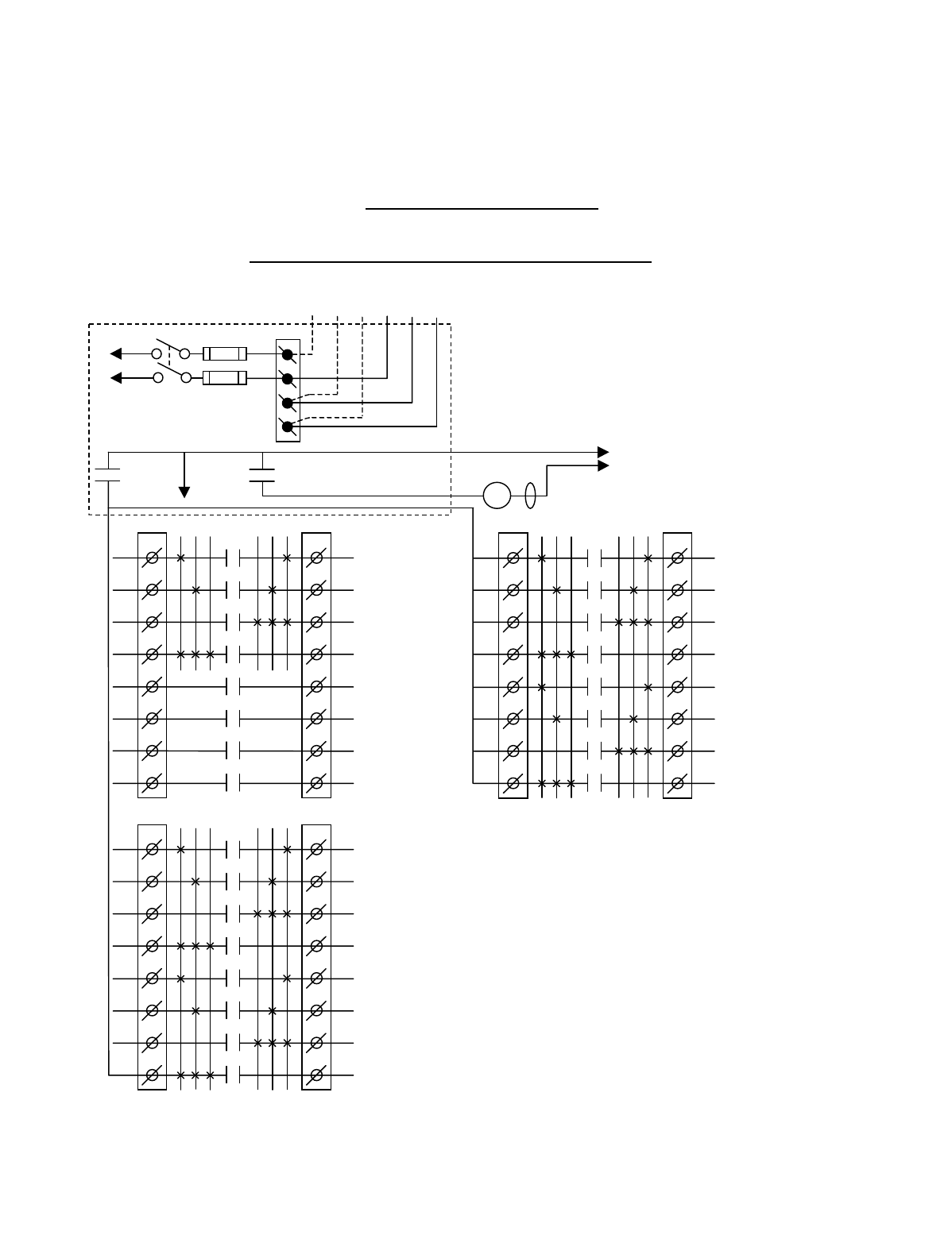
Appendix C - 10K16/24 Pendant and SLTX
Transmitter Programming (Continued)
C-26
TABLE 2(c)
Crane Control Type Selection: 10K24 TYPE 2 WIRING DIAGRAM
____________________________________________________________________________________________________
2-SPEED, 2-WINDINGS: ALL MOTIONS
CJ3
1
2
3
4
5
6
7
8
CJ2
1
2
3
4
5
6
7
8
K1
K2
K3
K4
K5
K6
K7
K8
3 2 1 1 2 3
AUX HOIST
HIGH SPD
AUX HOIST
LOW SPD
AUX HOIST
DOWN
AUX HOIST
UP
AUX TROLLEY
HIGH SPD
AUX TROLLEY
LOW SPD
AUX TROLLEY
SOUTH
AUX TROLLEY
NORTH
•
•
•
•
•
•
•
K1
K2
K3
K4
K5
K6
K7
K8
3 2 1 1 2 3
HOIST
HIGH SPD
HOIST
LOW SPD
HOIST
DOWN
HOIST
UP
TROLLEY
HIGH SPD
TROLLEY
LOW SPD
TROLLEY
SOUTH
TROLLEY
NORTH
•
•
•
•
•
•
AJ3
1
2
3
4
5
6
7
8
AJ2
1
2
3
4
5
6
7
8
K1
K2
K3
K4
K5
K6
K7
K8
3 2 1 1 2 3
BRIDGE
HIGH SPD
BRIDGE
LOW SPD
BRIDGE
WEST
BRIDGE
EAST
AUX 1
AUX 2
AUX 3
AUX 4
(*ALARM)
•
•
•
•
•
•
•
•
*NOTE: If it is necessary to operate the Alarm
Function during E-Stop condition, wire the input to the
alarm relay “AJ3-8” for the alarm function to the
control power hot side (relay “K1” (MR) on P/S Board
de-energized).
240 VAC 120 VAC
SW1
ON/OFF
TO POWER
TRANSFORMER E10171-X
P/S BOARD
MAIN LINE
CONTACTOR
TO
CONTROL
POWER
MLC
HOT
RET
(2)
K1 (MR)
(4)
•
•
• *See Note
•
240
120
FUSE J1
N
GND
(6)
K1 (MR)
(8)
•
•
•
•
Telemotive receiver output boards (E10112-X).
All connections to outputs AJ2, BJ2 and CJ2 are to
contactors, with proper arc suppressors across them,
controlling the appropriate listed function to the right.
For Multibox Systems
C1 Multibox 1
C2 Multibox 2
C3 Multibox 3
C4 Multibox 4
C5–C8 Match C5-C8 above if S3-4 on the Receiver CPU
Board is turned “OFF” .
C5-C8 Match C1-C4 respectively above if S3-4 on the
Receiver CPU Board is turned “ON”.

Appendix C - 10K16/24 Pendant and SLTX
Transmitter Programming (Continued)
C-27
TABLE 2(c)
Crane Control Type Selection: 10K24 TYPE 2 PROGRAMMING
____________________________________________________________________________________________________
2-SPEED, 2-WINDINGS: ALL MOTIONS
OUTPUT DEFINITIONS*
A4-A1 BRIDGE B4-B1 HOIST B8-B5 TROLLEY C4-C1 AUX HOIST C8-C5 AUX TROLLEY
A4 EAST B4 UP B8 NORTH C4 UP C8 NORTH
A3 WEST B3 DOWN B7 SOUTH C3 DOWN C7 SOUTH
A2 LOW SPD B2 LOW SPD B6 LOW SPD C2 LOW SPD C6 LOW SPD
A1 HIGH SPD B1 HIGH SPD B5 HIGH SPD C1 HIGH SPD C5 HIGH SPD
INDEPENDENT OUTPUTS
A8 AUX 4 (ALARM)
A7 AUX 3 (LATCHABLE S2-6)
A6 AUX 2 (LATCHABLE S2-7)
A5 AUX 1 (LATCHABLE S2-8)
*For Multibox Systems read Multibox details at the beginning of this section.
Transmitter Switch Select: Switch settings Sw4-5 to Sw4-8 are defined as follows:
SWITCH SETTINGS: TYPE Sw4-8 Sw4-7 Sw4-6 Sw4-5
2 OFF OFF ON OFF
OUTPUTS
A4 B4 B8 C4 C8
A3 B3 B7 C3 C7
A2 B2 B6 C2 C6
A1 B1 B5 C1 C5
DIR 1 DIR 2
1ST 2ND 3RD
3RD 2ND 1ST
OFF
ON
Sw4
For these switch
positions see the
beginning of this
section.
18234567
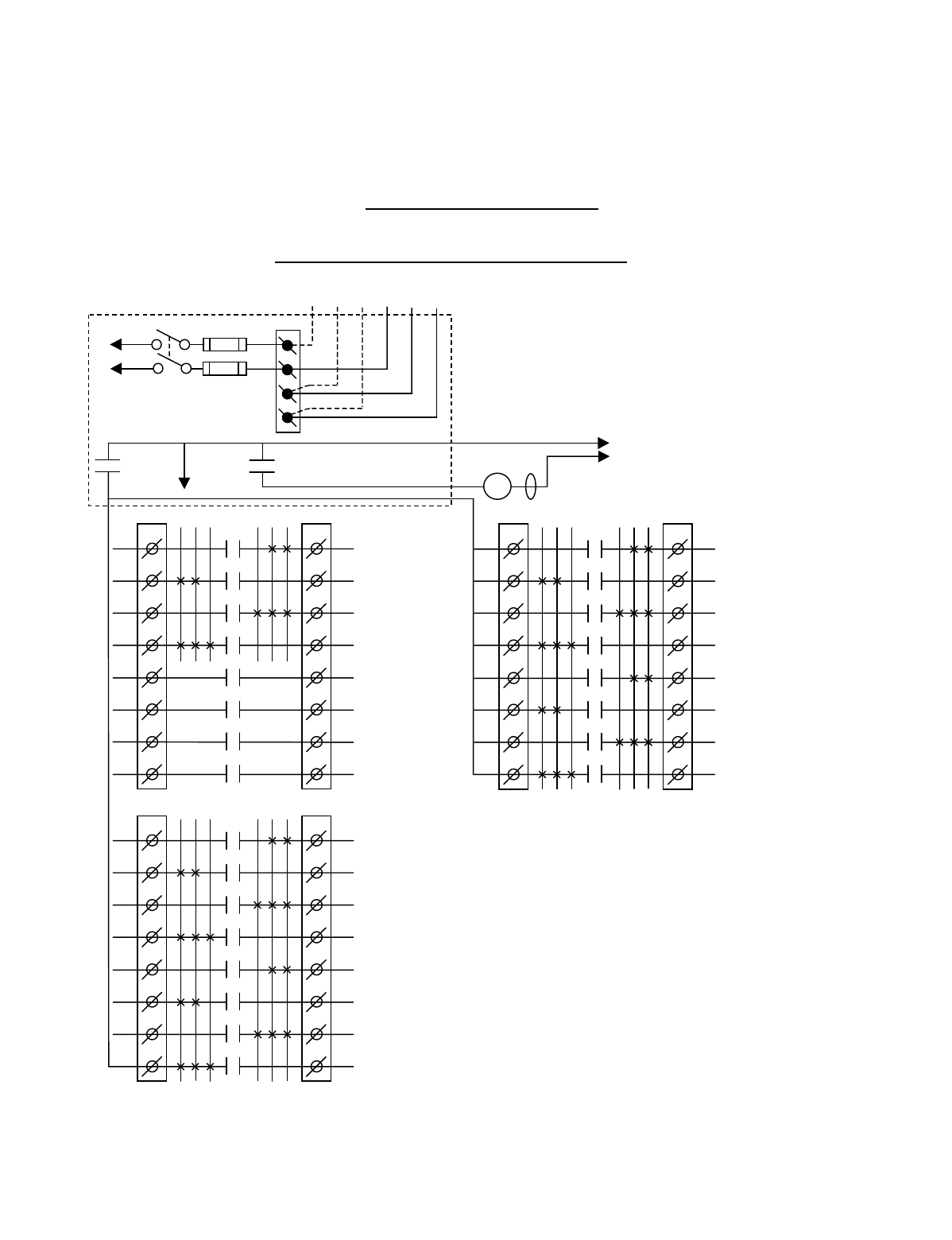
Appendix C - 10K16/24 Pendant and SLTX
Transmitter Programming (Continued)
C-28
TABLE 2(d)
Crane Control Type Selection: 10K24 TYPE 3 WIRING DIAGRAM
____________________________________________________________________________________________________
ACCO CONTROLS: ALL MOTIONS
CJ3
1
2
3
4
5
6
7
8
CJ2
1
2
3
4
5
6
7
8
K1
K2
K3
K4
K5
K6
K7
K8
3 2 1 1 2 3
AUX HOIST
DOWN 2ND SPD
AUX HOIST
UP 2ND SPD
AUX HOIST
DOWN
AUX HOIST
UP
AUX TROLLEY
SOUTH 2ND SPD
AUX TROLLEY
NORTH 2ND SPD
AUX TROLLEY
SOUTH
AUX TROLLEY
NORTH
•
•
•
•
•
•
•
BJ3
1
2
3
4
5
6
7
8
BJ2
1
2
3
4
5
6
7
8
K1
K2
K3
K4
K5
K6
K7
K8
3 2 1 1 2 3
HOIST
DOWN 2ND SPD
HOIST
UP 2ND SPD
HOIST
DOWN
HOIST
UP
TROLLEY
SOUTH 2ND SPD
TROLLEY
NORTH 2ND SPD
TROLLEY
SOUTH
TROLLEY
NORTH
•
•
•
•
•
•
AJ3
1
2
3
4
5
6
7
8
AJ2
1
2
3
4
5
6
7
8
K1
K2
K3
K4
K5
K6
K7
K8
3 2 1 1 2 3
BRIDGE
WEST 2ND SPD
BRIDGE
EAST 2ND SPD
BRIDGE
WEST
BRIDGE
EAST
AUX 1
AUX 2
AUX 3
AUX 4
(*ALARM)
•
•
•
•
•
•
•
•
*NOTE: If it is necessary to operate the Alarm
Function during E-Stop condition, wire the input to the
alarm relay “AJ3-8” for the alarm function to the
control power hot side (relay “K1” (MR) on P/S Board
de-energized).
240 VAC 120 VAC
SW1
ON/OFF
TO POWER
TRANSFORMER E10171-X
P/S BOARD
MAIN LINE
CONTACTOR
TO
CONTROL
POWER
MLC
HOT
RET
(2)
K1 (MR)
(4)
•
•
• *See Note
•
240
120
FUSE J1
N
GND
(6)
K1 (MR)
(8)
•
•
•
•
Telemotive receiver output boards (E10112-X).
All connections to outputs AJ2, BJ2 and CJ2 are to
contactors, with proper arc suppressors across them,
controlling the appropriate listed function to the right.
For Multibox Systems
C1 Multibox 1
C2 Multibox 2
C3 Multibox 3
C4 Multibox 4
C5–C8 Match C5-C8 above if S3-4 on the Receiver CPU
Board is turned “OFF” .
C5-C8 Match C1-C4 respectively above if S3-4 on the
Receiver CPU Board is turned “ON”.

Appendix C - 10K16/24 Pendant and SLTX
Transmitter Programming (Continued)
C-29
TABLE 2(d)
Crane Control Type Selection: 10K24 TYPE 3 PROGRAMMING
____________________________________________________________________________________________________
ACCO CONTROLS: ALL MOTIONS
OUTPUT DEFINITIONS*
A4-A1 BRIDGE B4-B1 HOIST B8-B5 TROLLEY C4-C1 AUX HOIST C8-C5 AUX TROLLEY
A4 EAST B4 UP B8 NORTH C4 UP C8 NORTH
A3 WEST B3 DOWN B7 SOUTH C3 DOWN C7 SOUTH
A2 EAST 2ND SPD B2 UP 2ND SPD B6 NORTH 2ND SPD C2 UP 2ND SPD C6 NORTH 2ND SPD
A1 WEST 2ND PD B1 DOWN 2ND SPD B5 SOUTH 2ND SPD C1 DOWN 2ND SPD C5 SOUTH 2ND SPD
INDEPENDENT OUTPUTS
A8 AUX 4 (ALARM)
A7 AUX 3 (LATCHABLE S2-6)
A6 AUX 2 (LATCHABLE S2-7)
A5 AUX 1 (LATCHABLE S2-8)
*For Multibox Systems read Multibox details at the beginning of this section.
Transmitter Switch Select: Switch settings Sw4-5 to Sw4-8 are defined as follows:
SWITCH SETTINGS: TYPE Sw4-8 Sw4-7 Sw4-6 Sw4-5
3OFF OFF ON ON
OUTPUTS
A4 B4 B8 C4 C8
A3 B3 B7 C3 C7
A2 B2 B6 C2 C6
A1 B1 B5 C1 C5
DIR 1 DIR 2
1ST 2ND 3RD
3RD 2ND 1ST
OFF
ON
Sw4
For these switch
positions see the
beginning of this
section.
18234567
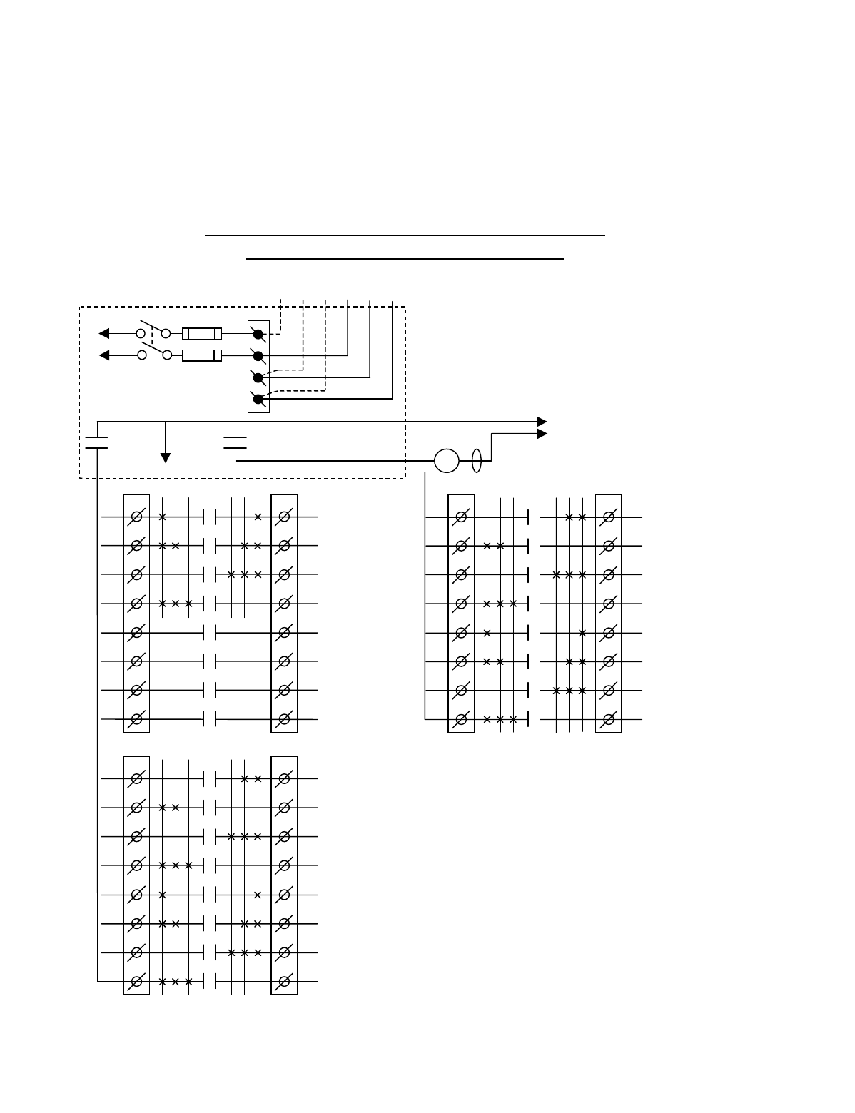
Appendix C - 10K16/24 Pendant and SLTX
Transmitter Programming (Continued)
C-30
TABLE 2(e)
Crane Control Type Selection: 10K24 TYPE 4 WIRING DIAGRAM
____________________________________________________________________________________________________
DEMAG: 2-SPEED, 2-WINDINGS for HOIST:
STANDARD BRIDGE and TROLLEY
CJ3
1
2
3
4
5
6
7
8
CJ2
1
2
3
4
5
6
7
8
K1
K2
K3
K4
K5
K6
K7
K8
3 2 1 1 2 3
AUX HOIST
DOWN 2ND SPD
AUX HOIST
UP 2ND SPD
AUX HOIST
DOWN
AUX HOIST
UP
AUX TROLLEY
3RD SPD
AUX TROLLEY
2ND SPD
AUX TROLLEY
SOUTH
AUX TROLLEY
NORTH
•
•
•
•
•
•
•
BJ3
1
2
3
4
5
6
7
8
BJ2
1
2
3
4
5
6
7
8
K1
K2
K3
K4
K5
K6
K7
K8
3 2 1 1 2 3
HOIST
DOWN 2ND SPD
HOIST
UP 2ND SPD
HOIST
DOWN
HOIST
UP
TROLLEY
3RD SPD
TROLLEY
2ND SPD
TROLLEY
SOUTH
TROLLEY
NORTH
•
•
•
•
•
•
AJ3
1
2
3
4
5
6
7
8
AJ2
1
2
3
4
5
6
7
8
K1
K2
K3
K4
K5
K6
K7
K8
3 2 1 1 2 3
BRIDGE
3RD SPD
BRIDGE
2ND SPD
BRIDGE
WEST
BRIDGE
EAST
AUX 1
AUX 2
AUX 3
AUX 4
(*ALARM)
•
•
•
•
•
•
•
•
*NOTE: If it is necessary to operate the Alarm
Function during E-Stop condition, wire the input to the
alarm relay “AJ3-8” for the alarm function to the
control power hot side (relay “K1” (MR) on P/S Board
de-energized).
240 VAC 120 VAC
SW1
ON/OFF
TO POWER
TRANSFORMER E10171-X
P/S BOARD
MAIN LINE
CONTACTOR
TO
CONTROL
POWER
MLC
HOT
RET
(2)
K1 (MR)
(4)
•
•
• *See Note
•
240
120
FUSE J1
N
GND
(6)
K1 (MR)
(8)
•
•
•
•
Telemotive receiver output boards (E10112-X).
All connections to outputs AJ2, BJ2 and CJ2 are to
contactors, with proper arc suppressors across them,
controlling the appropriate listed function to the right.
For Multibox Systems
C1 Multibox 1
C2 Multibox 2
C3 Multibox 3
C4 Multibox 4
C5–C8 Match C5-C8 above if S3-4 on the Receiver CPU
Board is turned “OFF” .
C5-C8 Match C1-C4 respectively above if S3-4 on the
Receiver CPU Board is turned “ON”.
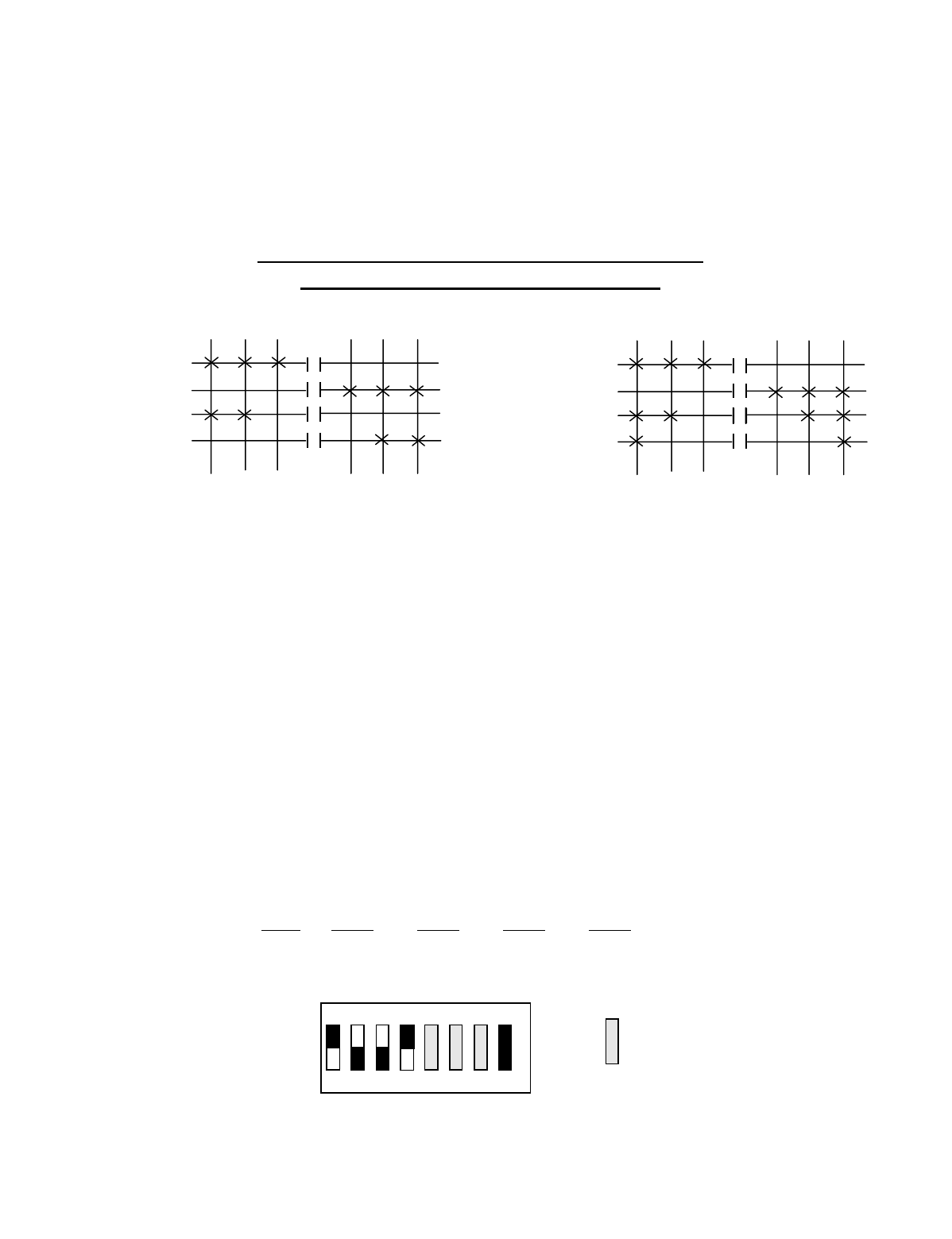
Appendix C - 10K16/24 Pendant and SLTX
Transmitter Programming (Continued)
C-31
TABLE 2(e)
Crane Control Type Selection: 10K24 TYPE 4 PROGRAMMING
____________________________________________________________________________________________________
DEMAG: 2-SPEED, 2-WINDINGS for HOIST:
STANDARD BRIDGE and TROLLEY
OUTPUT DEFINITIONS*
A4-A1 BRIDGE B4-B1 HOIST B8-B5 TROLLEY C4-C1 AUX HOIST C8-C5 AUX TROLLEY
A4 EAST B4 UP B8 NORTH C4 UP C8 NORTH
A3 WEST B3 DOWN B7 SOUTH C3 DOWN C7 SOUTH
A2 2ND SPD B2 UP 2ND SPD B6 2ND SPD C2 UP 2ND SPD C6 2ND SPD
A1 3RD SPD B1 DOWN 2ND SPD B5 3RD SPD C1 DOWN 2ND SPD C5 3RD SPD
INDEPENDENT OUTPUTS
A8 AUX 4 (ALARM)
A7 AUX 3 (LATCHABLE S2-6)
A6 AUX 2 (LATCHABLE S2-7)
A5 AUX 1 (LATCHABLE S2-8)
*For Multibox Systems read Multibox details at the beginning of this section.
Transmitter Switch Select: Switch settings Sw4-5 to Sw4-8 are defined as follows:
SWITCH SETTINGS: TYPE Sw4-8 Sw4-7 Sw4-6 Sw4-5
4 OFF ON ON OFF
OUTPUTS
B4 C4
B3 C3
B2 C2
B1 C1
DIR 1 DIR 2
1
S
T 2ND 3RD
OUTPUTS
A4 B8 C8
A3 B7 C7
A2 B6 C6
A1 B5 C5
DIR 1 DIR 2
1ST 2ND 3RD
3RD 2ND 1
S
T3RD 2ND 1ST
OFF
ON
Sw4
For these switch
positions see the
beginning of this
section.
18234567
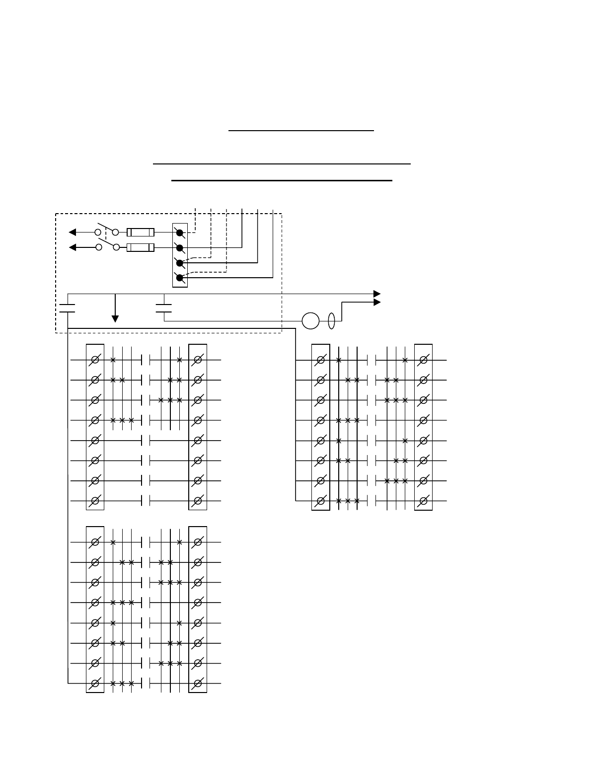
Appendix C - 10K16/24 Pendant and SLTX
Transmitter Programming (Continued)
C-32
TABLE 2(f)
Crane Control Type Selection: 10K24 TYPE 5 WIRING DIAGRAM
____________________________________________________________________________________________________
P&H: 2-SPEED, 2-WINDINGS for HOIST:
STANDARD BRIDGE and TROLLEY
CJ3
1
2
3
4
5
6
7
8
CJ2
1
2
3
4
5
6
7
8
K1
K2
K3
K4
K5
K6
K7
K8
3 2 1 1 2 3
AUX HOIST
HIGH SPD
AUX HOIST
LOW SPD
AUX HOIST
DOWN
AUX HOIST
UP
AUX TROLLEY
3RD SPD
AUX TROLLEY
2ND SPD
AUX TROLLEY
SOUTH
AUX TROLLEY
NORTH
•
•
•
•
•
•
•
BJ3
1
2
3
4
5
6
7
8
BJ2
1
2
3
4
5
6
7
8
K1
K2
K3
K4
K5
K6
K7
K8
3 2 1 1 2 3
HOIST
HIGH SPD
HOIST
LOW SPD
HOIST
DOWN
HOIST
UP
TROLLEY
3RD SPD
TROLLEY
2ND SPD
TROLLEY
SOUTH
TROLLEY
NORTH
•
•
•
•
•
•
AJ3
1
2
3
4
5
6
7
8
AJ2
1
2
3
4
5
6
7
8
K1
K2
K3
K4
K5
K6
K7
K8
3 2 1 1 2 3
BRIDGE
3RD SPD
BRIDGE
2ND SPD
BRIDGE
WEST
BRIDGE
EAST
AUX 1
AUX 2
AUX 3
AUX 4
(*ALARM)
•
•
•
•
•
•
•
•
*NOTE: If it is necessary to operate the Alarm
Function during E-Stop condition, wire the input to the
alarm relay “AJ3-8” for the alarm function to the
control power hot side (relay “K1” (MR) on P/S Board
de-energized).
240 VAC 120 VAC
SW1
ON/OFF
TO POWER
TRANSFORMER E10171-X
P/S BOARD
MAIN LINE
CONTACTOR
TO
CONTROL
POWER
MLC
HOT
RET
(2)
K1 (MR)
(4)
•
•
• *See Note
•
240
120
FUSE J1
N
GND
(6)
K1 (MR)
(8)
•
•
•
•
Telemotive receiver output boards (E10112-X).
All connections to outputs AJ2, BJ2 and CJ2 are to
contactors, with proper arc suppressors across them,
controlling the appropriate listed function to the right.
For Multibox Systems
C1 Multibox 1
C2 Multibox 2
C3 Multibox 3
C4 Multibox 4
C5–C8 Match C5-C8 above if S3-4 on the Receiver CPU
Board is turned “OFF” .
C5-C8 Match C1-C4 respectively above if S3-4 on the
Receiver CPU Board is turned “ON”.
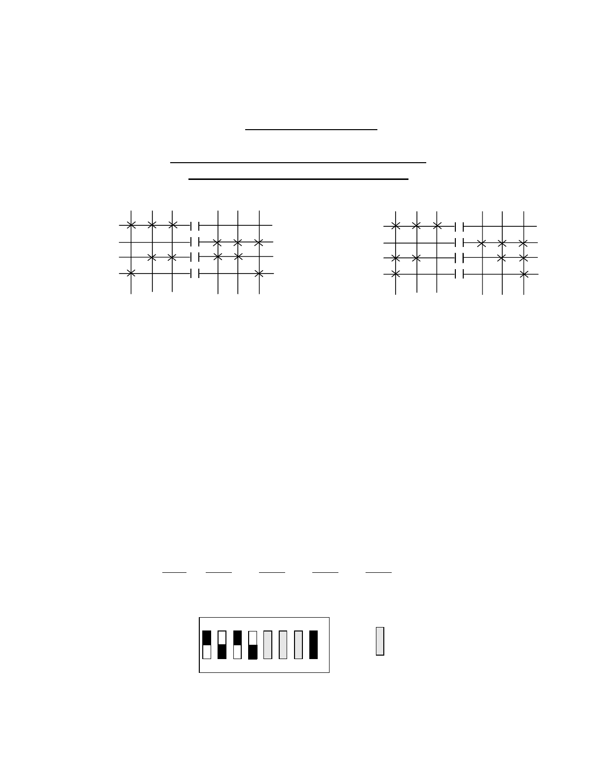
Appendix C - 10K16/24 Pendant and SLTX
Transmitter Programming (Continued)
C-33
TABLE 2(f)
Crane Control Type Selection: 10K24 TYPE 5 PROGRAMMING
____________________________________________________________________________________________________
P&H: 2-SPEED, 2-WINDINGS for HOIST:
STANDARD BRIDGE and TROLLEY
OUTPUT DEFINITIONS*
A4-A1 BRIDGE B4-B1 HOIST B8-B5 TROLLEY C4-C1 AUX HOIST C8-C5 AUX TROLLEY
A4 EAST B4 UP B8 NORTH C4 UP C8 NORTH
A3 WEST B3 DOWN B7 SOUTH C3 DOWN C7 SOUTH
A2 2ND SPD B2 LOW SPD B6 2ND SPD C2 LOW SPD C6 2ND SPD
A1 3RD SPD B1 HIGH SPD B5 3RD SPD C1 HIGH SPD C5 3RD SPD
INDEPENDENT OUTPUTS
A8 AUX 4 (ALARM)
A7 AUX 3 (LATCHABLE S2-6)
A6 AUX 2 (LATCHABLE S2-7)
A5 AUX 1 (LATCHABLE S2-8)
*For Multibox Systems read Multibox details at the beginning of this section.
Transmitter Switch Select: Switch settings Sw4-5 to Sw4-8 are defined as follows:
SWITCH SETTINGS: TYPE Sw4-8 Sw4-7 Sw4-6 Sw4-5
5OFF ON OFF ON
OUTPUTS
B4 C4
B3 C3
B2 C2
B1 C1
DIR 1 DIR 2
1
S
T 2ND 3RD
OUTPUTS
A4 B8 C8
A3 B7 C7
A2 B6 C6
A1 B5 C5
DIR 1 DIR 2
1ST 2ND 3RD
3RD 2ND 1
S
T3RD 2ND 1ST
OFF
ON
Sw4
For these switch
positions see the
beginning of this
section.
18234567
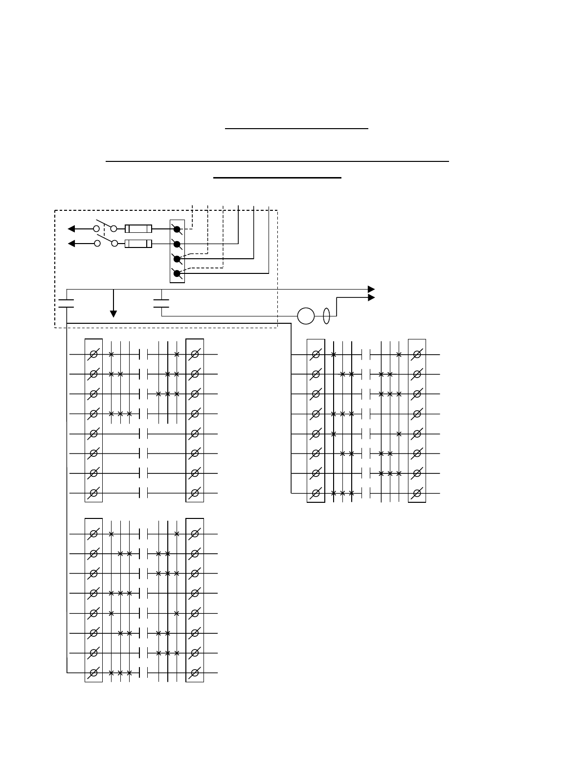
Appendix C - 10K16/24 Pendant and SLTX
Transmitter Programming (Continued)
C-34
TABLE 2(g)
Crane Control Type Selection: 10K24 TYPE 6 WIRING DIAGRAM
____________________________________________________________________________________________________
P&H: 2-SPEED, 2-WINDINGS for HOIST and TROLLEY:
STANDARD BRIDGE
CJ3
1
2
3
4
5
6
7
8
CJ2
1
2
3
4
5
6
7
8
K1
K2
K3
K4
K5
K6
K7
K8
3 2 1 1 2 3
AUX HOIST
HIGH SPD
AUX HOIST
LOW SPD
AUX HOIST
DOWN
AUX HOIST
UP
AUX TROLLEY
HIGH SPD
AUX TROLLEY
LOW SPD
AUX TROLLEY
SOUTH
AUX TROLLEY
NORTH
•
•
•
•
•
•
•
BJ3
1
2
3
4
5
6
7
8
BJ2
1
2
3
4
5
6
7
8
K1
K2
K3
K4
K5
K6
K7
K8
3 2 1 1 2 3
HOIST
HIGH SPD
HOIST
LOW SPD
HOIST
DOWN
HOIST
UP
TROLLEY
HIGH SPD
TROLLEY
LOW SPD
TROLLEY
SOUTH
TROLLEY
NORTH
•
•
•
•
•
•
AJ3
1
2
3
4
5
6
7
8
AJ2
1
2
3
4
5
6
7
8
K1
K2
K3
K4
K5
K6
K7
K8
3 2 1 1 2 3
BRIDGE
3RD SPD
BRIDGE
2ND SPD
BRIDGE
WEST
BRIDGE
EAST
AUX 1
AUX 2
AUX 3
AUX 4
(*ALARM)
•
•
•
•
•
•
•
•
*NOTE: If it is necessary to operate the Alarm
Function during E-Stop condition, wire the input to the
alarm relay “AJ3-8” for the alarm function to the
control power hot side (relay “K1” (MR) on P/S Board
de-energized).
240 VAC 120 VAC
SW1
ON/OFF
TO POWER
TRANSFORMER E10171-X
P/S BOARD
MAIN LINE
CONTACTOR
TO
CONTROL
POWER
MLC
HOT
RET
(2)
K1 (MR)
(4)
•
•
• *See Note
•
240
120
FUSE J1
N
GND
(6)
K1 (MR)
(8)
•
•
•
•
Telemotive receiver output boards (E10112-X).
All connections to outputs AJ2, BJ2 and CJ2 are to
contactors, with proper arc suppressors across them,
controlling the appropriate listed function to the right.
For Multibox Systems
C1 Multibox 1
C2 Multibox 2
C3 Multibox 3
C4 Multibox 4
C5–C8 Match C5-C8 above if S3-4 on the Receiver CPU
Board is turned “OFF” .
C5-C8 Match C1-C4 respectively above if S3-4 on the
Receiver CPU Board is turned “ON”.
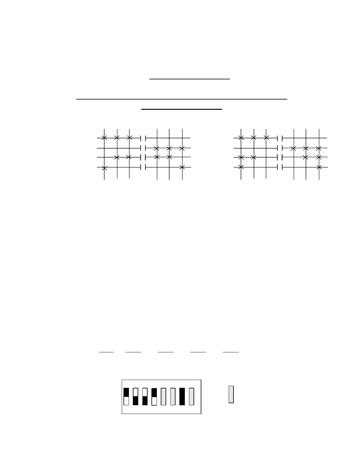
Appendix C - 10K16/24 Pendant and SLTX
Transmitter Programming (Continued)
C-35
TABLE 2(g)
Crane Control Type Selection: 10K24 TYPE 6 PROGRAMMING
____________________________________________________________________________________________________
P&H: 2-SPEED, 2-WINDINGS for HOIST and TROLLEY:
STANDARD BRIDGE
OUTPUT DEFINITIONS*
A4-A1 BRIDGE B4-B1 HOIST B8-B5 TROLLEY C4-C1 AUX HOIST C8-C5 AUX TROLLEY
A4 EAST B4 UP B8 NORTH C4 UP C8 NORTH
A3 WEST B3 DOWN B7 SOUTH C3 DOWN C7 SOUTH
A2 2ND SPD B2 LOW SPD B6 LOW SPD C2 LOW SPD C6 LOW SPD
A1 3RD SPD B1 HIGH SPD B5 HIGH SPD C1 HIGH SPD C5 HIGH SPD
INDEPENDENT OUTPUTS
A8 AUX 4 (ALARM)
A7 AUX 3 (LATCHABLE S2-6)
A6 AUX 2 (LATCHABLE S2-7)
A5 AUX 1 (LATCHABLE S2-8)
*For Multibox Systems read Multibox details at the beginning of this section.
Transmitter Switch Select: Switch settings Sw4-5 to Sw4-8 are defined as follows:
SWITCH SETTINGS: TYPE Sw4-8 Sw4-7 Sw4-6 Sw4-5
6 OFF ON ON OFF
OUTPUTS
B4 B8 C4 C8
B3 B7 C3 C7
B2 B6 C2 C6
B1 B5 C1 C5
DIR 1 DIR 2
1ST 2ND 3RD
OUTPUTS
A4
A3
A2
A1
DIR 1 DIR 2
1ST 2ND 3RD
3RD 2ND 1ST
3RD 2ND 1
S
T
OFF
ON
Sw4
For these switch
positions see the
beginning of this
section.
18234567
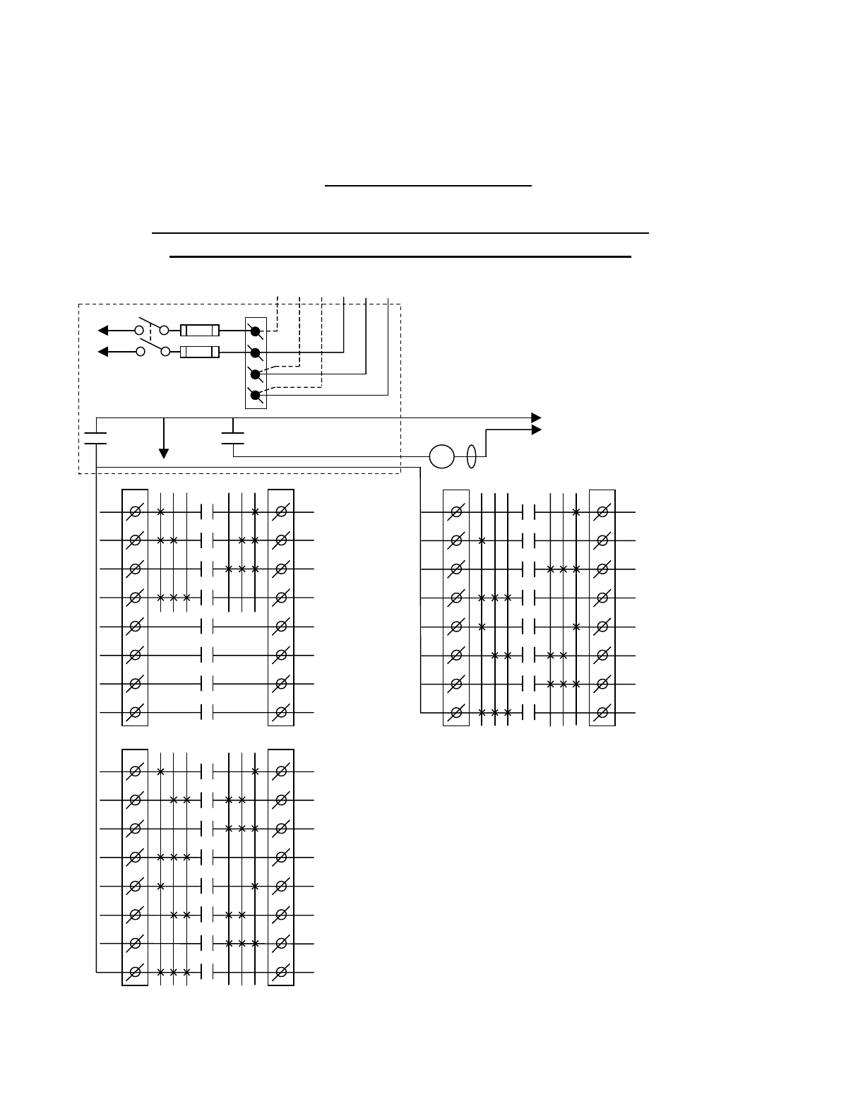
Appendix C - 10K16/24 Pendant and SLTX
Transmitter Programming (Continued)
C-36
TABLE 2(h)
Crane Control Type Selection: 10K24 TYPE 7 WIRING DIAGRAM
____________________________________________________________________________________________________
P&H: 2-SPEED, 2-WINDINGS HOIST #1 and TROLLEYS
With CREEP SPEED HOIST #2, STANDARD BRIDGE
CJ3
1
2
3
4
5
6
7
8
CJ2
1
2
3
4
5
6
7
8
K1
K2
K3
K4
K5
K6
K7
K8
3 2 1 1 2 3
AUX HOIST
DOWN HIGH SPD
AUX HOIST
UP HIGH SPD
AUX HOIST
DOWN
AUX HOIST
UP
AUX TROLLEY
HIGH SPD
AUX TROLLEY
LOW SPD
AUX TROLLEY
SOUTH
AUX TROLLEY
NORTH
•
•
•
•
•
•
•
BJ3
1
2
3
4
5
6
7
8
BJ2
1
2
3
4
5
6
7
8
K1
K2
K3
K4
K5
K6
K7
K8
3 2 1 1 2 3
HOIST
HIGH SPD
HOIST
LOW SPD
HOIST
DOWN
HOIST
UP
TROLLEY
HIGH SPD
TROLLEY
LOW SPD
TROLLEY
SOUTH
TROLLEY
NORTH
•
•
•
•
•
•
AJ3
1
2
3
4
5
6
7
8
AJ2
1
2
3
4
5
6
7
8
K1
K2
K3
K4
K5
K6
K7
K8
3 2 1 1 2 3
BRIDGE
3RD SPD
BRIDGE
2ND SPD
BRIDGE
WEST
BRIDGE
EAST
AUX 1
AUX 2
AUX 3
AUX 4
(*ALARM)
•
•
•
•
•
•
•
•
*NOTE: If it is necessary to operate the Alarm
Function during E-Stop condition, wire the input to the
alarm relay “AJ3-8” for the alarm function to the
control power hot side (relay “K1” (MR) on P/S Board
de-energized).
240 VAC 120 VAC
SW1
ON/OFF
TO POWER
TRANSFORMER E10171-X
P/S BOARD
MAIN LINE
CONTACTOR
TO
CONTROL
POWER
MLC
HOT
RET
(2)
K1 (MR)
(4)
•
•
• *See Note
•
240
120
FUSE J1
N
GND
(6)
K1 (MR)
(8)
•
•
•
•
Telemotive receiver output boards (E10112-X).
All connections to outputs AJ2, BJ2 and CJ2 are to
contactors, with proper arc suppressors across them,
controlling the appropriate listed function to the right.
For Multibox Systems
C1 Multibox 1
C2 Multibox 2
C3 Multibox 3
C4 Multibox 4
C5–C8 Match C5-C8 above if S3-4 on the Receiver CPU
Board is turned “OFF” .
C5-C8 Match C1-C4 respectively above if S3-4 on the
Receiver CPU Board is turned “ON”.
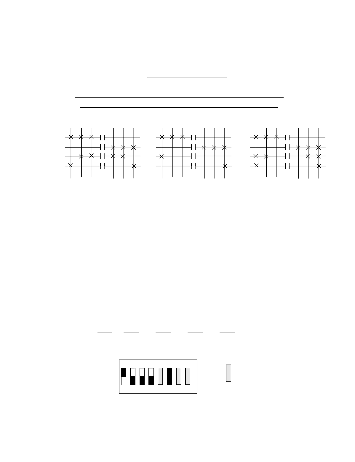
Appendix C - 10K16/24 Pendant and SLTX
Transmitter Programming (Continued)
C-37
TABLE 2(h)
Crane Control Type Selection: 10K24 TYPE 7 PROGRAMMING
____________________________________________________________________________________________________
P&H: 2-SPEED, 2-WINDINGS HOIST #1 and TROLLEYS
With CREEP SPEED HOIST #2, STANDARD BRIDGE
OUTPUT DEFINITIONS*
A4-A1 BRIDGE B4-B1 HOIST B8-B5 TROLLEY C4-C1 AUX HOIST C8-C5 AUX TROLLEY
A4 EAST B4 UP B8 NORTH C4 UP C8 NORTH
A3 WEST B3 DOWN B7 SOUTH C3 DOWN C7 SOUTH
A2 2ND SPD B2 LOW SPD B6 LOW SPD C2 UP HIGH SPD C6 LOW SPD
A1 3RD SPD B1 HIGH SPD B5 HIGH SPD C1 DOWN HIGH SPD C5 HIGH SPD
INDEPENDENT OUTPUTS
A8 AUX 4 (ALARM)
A7 AUX 3 (LATCHABLE S2-6)
A6 AUX 2 (LATCHABLE S2-7)
A5 AUX 1 (LATCHABLE S2-8)
*For Multibox Systems read Multibox details at the beginning of this section.
Transmitter Switch Select: Switch settings Sw4-5 to Sw4-8 are defined as follows:
SWITCH SETTINGS: TYPE Sw4-8 Sw4-7 Sw4-6 Sw4-5
7 OFF ON ON ON
NOTE: TANDEM HOIST AND TROLLEY IS NOT AVAILABLE IN THIS CONFIGURATION
OUTPUTS
B4 B8 C8
B3 B7 C7
B2 B6 C6
B1 B5 C5
OUTPUTS
A4
A3
A2
A1
DIR 1 DIR 2
1
ST
2
ND
3
RD
OUTPUTS
C4
C3
C2
C1
3
RD
2
ND
1
ST
DIR 1 DIR 2
1
ST
2
ND
3
RD
DIR 1 DIR 2
1
ST
2
ND
3
RD
3
RD
2
ND
1
ST
3
RD
2
ND
1
ST
OFF
ON
Sw4
For these switch
positions see the
beginning of this
section.
18234567
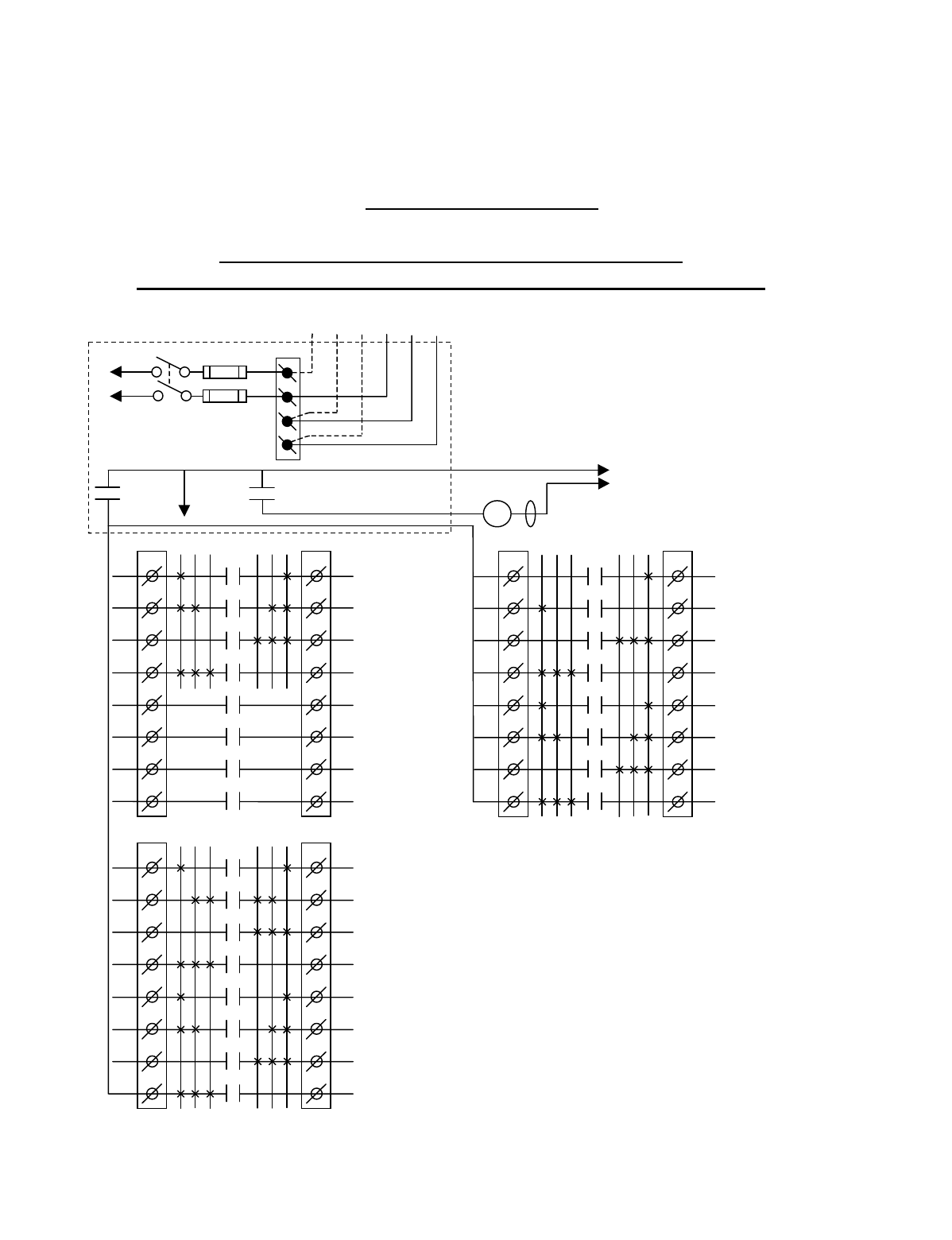
Appendix C - 10K16/24 Pendant and SLTX
Transmitter Programming (Continued)
C-38
TABLE 2(i)
Crane Control Type Selection: 10K24 TYPE 8 WIRING DIAGRAM
____________________________________________________________________________________________________
P&H: 2-SPEED, 2-WINDINGS HOIST #1: With
CREEP SPEED HOIST #2, STANDARD BRIDGE and TROLLEYS
CJ3
1
2
3
4
5
6
7
8
CJ2
1
2
3
4
5
6
7
8
K1
K2
K3
K4
K5
K6
K7
K8
3 2 1 1 2 3
AUX HOIST
DOWN HIGH SPD
AUX HOIST
UP HIGH SPD
AUX HOIST
DOWN
AUX HOIST
UP
AUX TROLLEY
3RD SPD
AUX TROLLEY
2ND SPD
AUX TROLLEY
SOUTH
AUX TROLLEY
NORTH
•
•
•
•
•
•
•
K1
K2
K3
K4
K5
K6
K7
K8
3 2 1 1 2 3
•
•
•
•
•
•
AJ3
1
2
3
4
5
6
7
8
AJ2
1
2
3
4
5
6
7
8
K1
K2
K3
K4
K5
K6
K7
K8
3 2 1 1 2 3
BRIDGE
3RD SPD
BRIDGE
2ND SPD
BRIDGE
WEST
BRIDGE
EAST
AUX 1
AUX 2
AUX 3
AUX 4
(*ALARM)
•
•
•
•
•
•
•
•
*NOTE: If it is necessary to operate the Alarm
Function during E-Stop condition, wire the input to the
alarm relay “AJ3-8” for the alarm function to the
control power hot side (relay “K1” (MR) on P/S Board
de-energized).
240 VAC 120 VAC
SW1
ON/OFF
TO POWER
TRANSFORMER E10171-X
P/S BOARD
MAIN LINE
CONTACTOR
TO
CONTROL
POWER
MLC
HOT
RET
(2)
K1 (MR)
(4)
•
•
• *See Note
•
240
120
FUSE J1
N
GND
(6)
K1 (MR)
(8)
•
•
•
•
Telemotive receiver output boards (E10112-X).
All connections to outputs AJ2, BJ2 and CJ2 are to
contactors, with proper arc suppressors across them,
controlling the appropriate listed function to the right.
For Multibox Systems
C1 Multibox 1
C2 Multibox 2
C3 Multibox 3
C4 Multibox 4
C5–C8 Match C5-C8 above if S3-4 on the Receiver CPU
Board is turned “OFF” .
C5-C8 Match C1-C4 respectively above if S3-4 on the
Receiver CPU Board is turned “ON”.
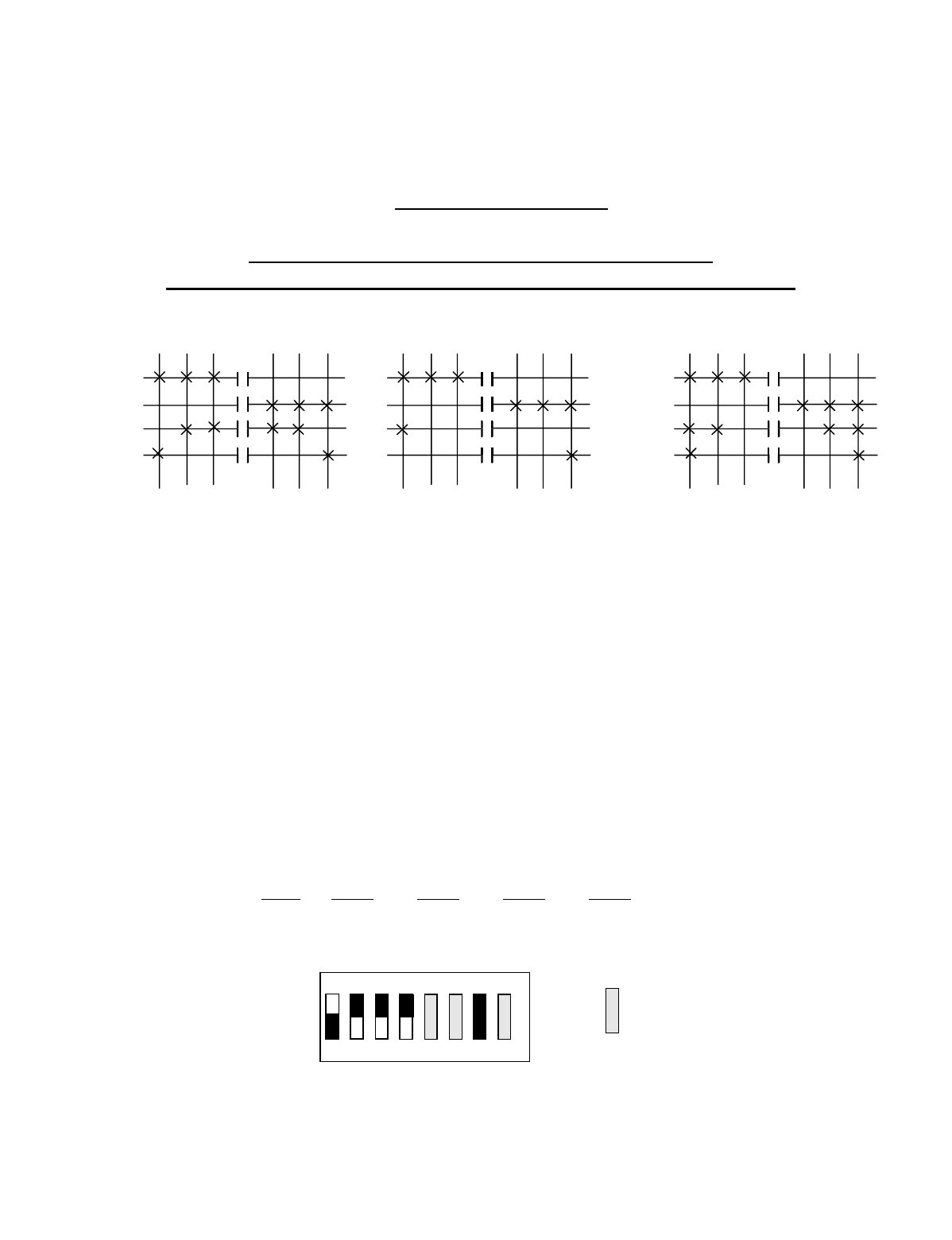
Appendix C - 10K16/24 Pendant and SLTX
Transmitter Programming (Continued)
C-39
TABLE 2(i)
Crane Control Type Selection: 10K24 TYPE 8 PROGRAMMING
____________________________________________________________________________________________________
P&H: 2-SPEED, 2-WINDINGS HOIST #1: With
CREEP SPEED HOIST #2, STANDARD BRIDGE and TROLLEYS
OUTPUT DEFINITIONS*
A4-A1 BRIDGE B4-B1 HOIST B8-B5 TROLLEY C4-C1 AUX HOIST C8-C5 AUX TROLLEY
A4 EAST B4 UP B8 NORTH C4 UP C8 NORTH
A3 WEST B3 DOWN B7 SOUTH C3 DOWN C7 SOUTH
A2 2ND SPD B2 LOW SPD B6 2ND SPD C2 UP HIGH SPD C6 2ND SPD
A1 3RD SPD B1 HIGH SPD B5 3RD SPD C1 DOWN HIGH SPD C5 3RD SPD
INDEPENDENT OUTPUTS
A8 AUX 4 (ALARM)
A7 AUX 3 (LATCHABLE S2-6)
A6 AUX 2 (LATCHABLE S2-7)
A5 AUX 1 (LATCHABLE S2-8)
*For Multibox Systems read Multibox details at the beginning of this section.
Transmitter Switch Select: Switch settings Sw4-5 to Sw4-8 are defined as follows:
SWITCH SETTINGS: TYPE Sw4-8 Sw4-7 Sw4-6 Sw4-5
8 ON OFF OFF OFF
NOTE: TANDEM HOIST AND TROLLEY IS NOT AVAILABLE IN THIS CONFIGURATION
O
UTPUTS
B4
B3
B2
B1
OUTPUTS
A4 B8 C8
A3 B7 C7
A2 B6 C6
A1 B5 C5
DIR 1 DIR 2
1
ST
2
ND
3
RD
OUTPUTS
C4
C3
C2
C1
3
RD
2
ND
1
ST
DIR 1 DIR 2
1
ST
2
ND
3
RD
DIR 1 DIR 2
1
ST
2
ND
3
RD
3
RD
2
ND
1
ST
3
RD
2
ND
1
ST
OFF
ON
Sw4
For these switch
positions see the
beginning of this
section.
18234567
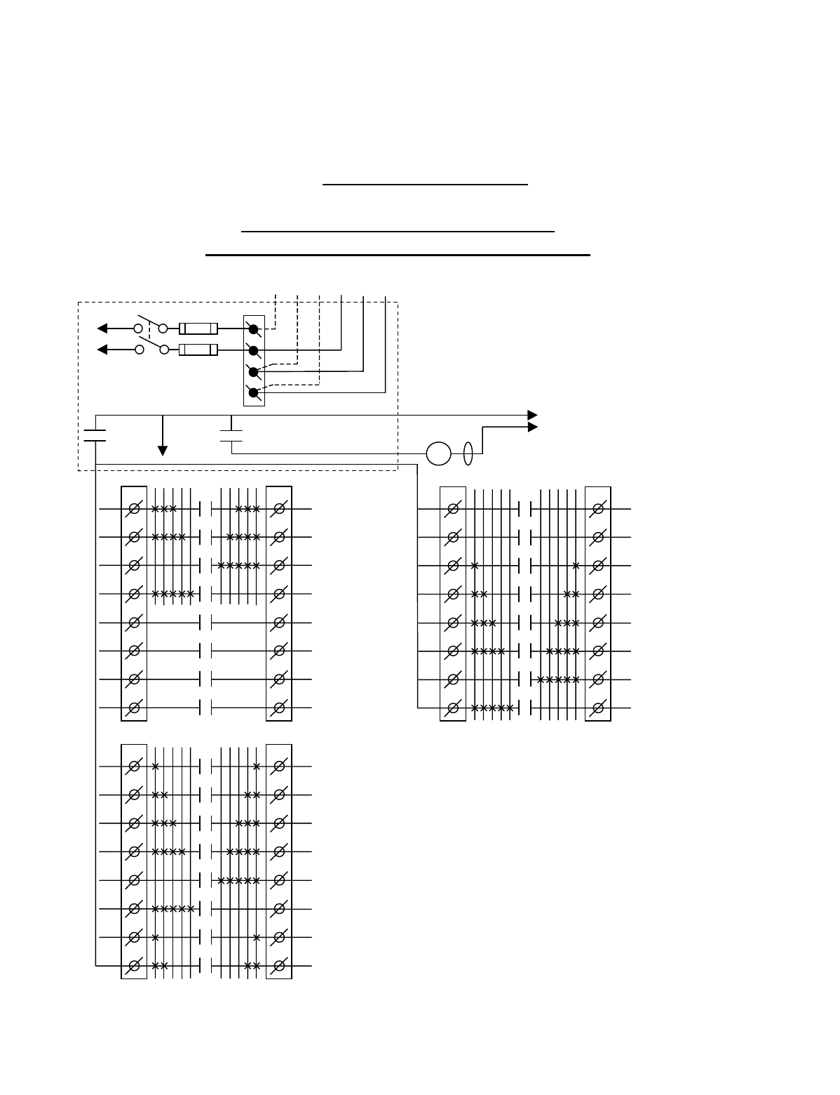
Appendix C - 10K16/24 Pendant and SLTX
Transmitter Programming (Continued)
C-40
TABLE 2(j)
Crane Control Type Selection: 10K24 TYPE 9 WIRING DIAGRAM
____________________________________________________________________________________________________
STANDARD 5-SPEED, INTERFACE
With SLTX LEVER SWITCH TRANSMITTER
CJ3
1
2
3
4
5
6
7
8
CJ2
1
2
3
4
5
6
7
8
K1
K2
K3
K4
K5
K6
K7
K8
HOIST/TROLLEY
**SELECT #1
HOIST/TROLLEY
**SELECT #2
HOIST
5TH SPD
HOIST
4TH SPD
HOIST
3RD SPD
HOIST
2ND SPD
HOIST
DOWN
HOIST
UP
•
•
•
•
•
•
•
BJ3
1
2
3
4
5
6
7
8
BJ2
1
2
3
4
5
6
7
8
K1
K2
K3
K4
K5
K6
K7
K8
TROLLEY
5TH SPD
TROLLEY
4TH SPD
TROLLEY
3RD SPD
TROLLEY
2ND SPD
TROLLEY
SOUTH
TROLLEY
NORTH
BRIDGE
5TH SPD
BRIDGE
4TH SPD
•
•
•
•
•
•
AJ3
1
2
3
4
5
6
7
8
AJ2
1
2
3
4
5
6
7
8
K1
K2
K3
K4
K5
K6
K7
K8
BRIDGE
3RD SPD
BRIDGE
2ND SPD
BRIDGE
WEST
BRIDGE
EAST
AUX 1
AUX 2
AUX 3
AUX 4
(*ALARM)
•
•
•
•
•
•
•
•
*NOTE: If it is necessary to operate the Alarm
Function during E-Stop condition, wire the input to the
alarm relay “AJ3-8” for the alarm function to the
control power hot side (relay “K1” (MR) on P/S Board
de-energized).
Telemotive receiver output boards
(E10112-X).
All connections to outputs AJ2, BJ2
and CJ2 are to contactors, with proper
arc suppressors across them,
controlling the appropriate listed
function to the right.
**The select function can be inverted
by turning Receiver CPU switch S4
position 4 to “ON”. See the details at
the beginning of this section.
240 VAC 120 VAC
SW1
ON/OFF
TO POWER
TRANSFORMER E10171-X
P/S BOARD
MAIN LINE
CONTACTOR
TO
CONTROL
POWER
MLC
HOT
RET
(2)
K1 (MR)
(4)
•
•
• *See Note
•
240
120
FUSE J1
N
GND
(6)
K1 (MR)
(8)
•
•
•
•
5 4 3 2 1
1 2 3 4 5
1 2 3 4 5
5 4 3 2 15 4 3 2 1 1 2 3 4 5
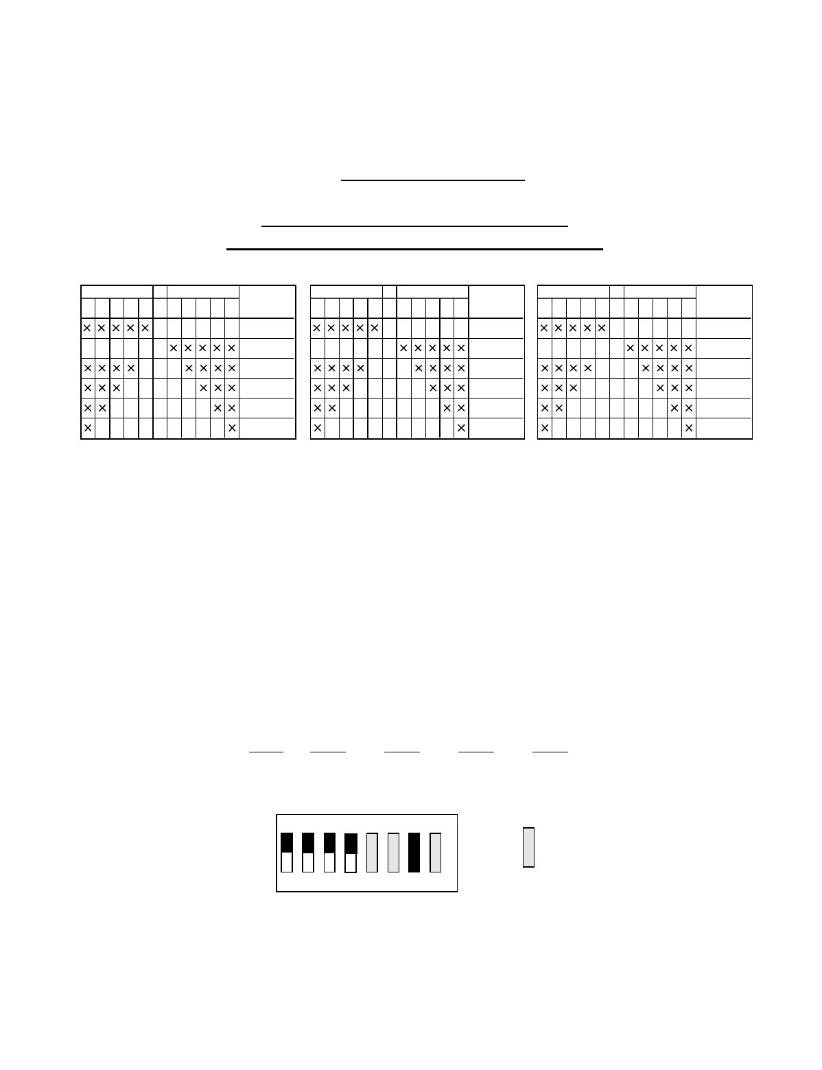
Appendix C - 10K16/24 Pendant and SLTX
Transmitter Programming (Continued)
C-41
TABLE 2(j)
Crane Control Type Selection: 10K24 TYPE 9 PROGRAMMING
____________________________________________________________________________________________________
STANDARD 5-SPEED, INTERFACE
With SLTX LEVER SWITCH TRANSMITTER
OUTPUT DEFINITIONS
A4-A1 BRIDGE B8-B7 BRIDGE B6-B5 TROLLEY B4-B1 TROLLEY C8-C5 HOIST C4-C3 HOIST
A4 EAST B8 4TH SPD B4 2ND SPD C8 UP C4 4TH SPD
A3 WEST B7 5TH SPD B3 3RD SPD C7 DOWN C3 5TH SPD
A2 2ND SPD B6 NORTH B2 4TH SPD C6 2ND SPD
A1 3RD SPD B5 SOUTH B1 5TH SPD C5 3RD SPD
INDEPENDENT OUTPUTS
A8 AUX 4 (ALARM)
A7 AUX 3 (LATCHABLE S2-6)
A6 AUX 2 (LATCHABLE S2-7) C2 HOIST/TROLLEY SELECT #2
A5 AUX 1 (LATCHABLE S2-8) C1 HOIST/TROLLEY SELECT #1
SLTX Transmitter Switch Select: Switch settings Sw4-5 to Sw4-8 are defined as follows:
SLTX SWITCH SETTINGS: TYPE Sw4-8 Sw4-7 Sw4-6 Sw4-5
8 OFF OFF OFF OFF
J2 OUTPUT
TERMINAL
A4 BRIDGE
A3 BRIDGE
A2 BRIDGE
A1 BRIDGE
B8 BRIDGE
B7 BRIDGE
EAST
OFF
W EST
J2 OUTPUT
TERMINAL
B6 TROLLEY
B5 TROLLEY
B4 TROLLEY
B3 TROLLEY
B2 TROLLEY
B1 TROLLEY
NORTH
OFF
SOUTH
J2 OUTPUT
TERMINAL
C8 HOIST
C7 HOIST
C6 HOIST
C5 HOIST
C4 HOIST
C3 HOIST
UP
OFF
DOW N
OFF
ON
Sw4
For these switch
positions see the
beginning of this
section.
18234567
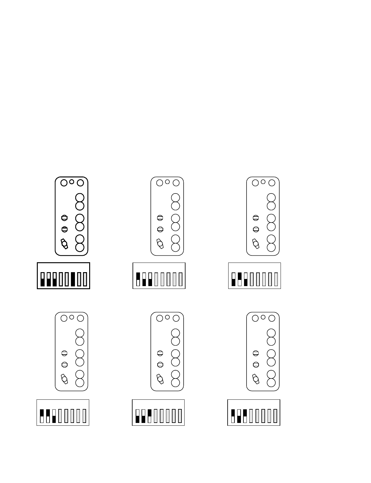
Appendix C - 10K16/24 Pendant and SLTX
Transmitter Programming (Continued)
C-42
TABLE 2(k)
Repositioning of transmitter pushbutton switch functions for pendant only.
____________________________________________________________________________________________________
SW3 positions 1 through 3 can change the functional positions of the switches controlling trolley, hoist and bridge. This can
be usefull to align East/West and North/South. This reconfiguration does NOT affect receiver wiring.
____________________________________________________________________________________________________
WARNING
CHANGING THESE SWITCHES CHANGES THE FUNCTIONAL OPERATION OF THE CRANE IN RELATIONSHIP
TO THE TRANSMITTER BUTTON BEING DEPRESSED. THE FUNCTIONAL OPERATION OF THE CRANE
SHOULD NEVER BE CHANGED WITHOUT ALL PERSONNEL RESPONSIBLE FOR CRANE OPERATION BEING
NOTIFIED PRIOR TO MODIFICATION.
123456
7
8
ON
OFF
HOIST
TROLLEY
BRIDGE
HOIST
BRIDGE
TROLLEY
BRIDGE
TROLLEY
HOIST
BRIDGE
HOIST
TROLLEY
TROLLEY
HOIST
BRIDGE
TROLLEY
BRIDGE
HOIST
Standard Configuration
123456
7
8ON
OFF
123456
7
8ON
OFF
123456
7
8ON
OFF
123456
7
8ON
OFF
123456
7
8ON
OFF