Telit Wireless Solutions BRSI Bluetooth Module User Manual BlueRS I Designguide eng V1 2
Stollmann E+V GmbH Bluetooth Module BlueRS I Designguide eng V1 2
OEM Instructions
Stollmann
E + V GmbH
BlueRS+I
DesignGuide
Author: cl Date of Savin
g
: 19.03.04 Ref: Revision: 1.2 Pa
g
e 1 of 22
BlueRS+I
DesignGuide

Stollmann
E + V GmbH
BlueRS+I
DesignGuide
Author: cl Date of Savin
g
: 19.03.04 Ref: Revision: 1.2 Pa
g
e 2 of 22
Content
1 Objective............................................................................................................. 4
2 Product Description ............................................................................................ 4
2.1 Product Versions............................................................................................. 4
2.1.1 Power Supply........................................................................................... 4
2.2 Operation Modes............................................................................................. 4
2.2.1 AT-Mode .................................................................................................. 4
2.2.2 Autoconnect ............................................................................................. 4
2.2.3 Autoconnect DTR..................................................................................... 4
2.3 Security ........................................................................................................... 5
2.4 Block Diagram................................................................................................. 5
3 Applications ........................................................................................................ 6
3.1 Cable Replacement Serial Point-to-point ........................................................ 6
3.2 Cable Replacement Multipoint ........................................................................ 6
3.3 LAN Access..................................................................................................... 7
Terminal Server...................................................................................................... 7
3.5 PC Client ......................................................................................................... 7
4 Software Interfaces............................................................................................. 8
4.1 AT Commands ................................................................................................ 8
4.1.1 Configuration Commands ........................................................................ 8
4.1.2 Connection Commands............................................................................ 8
4.2 Autoconnect .................................................................................................... 9
4.3 Security ........................................................................................................... 9
5 Hardware .......................................................................................................... 10
5.1 Dimensions.................................................................................................... 10
5.2 Interfaces, Pin Assignment............................................................................ 11
5.2.1 Serial Interface....................................................................................... 11
5.2.2 Connector P1 ......................................................................................... 12
5.2.3 Bluetooth Interface................................................................................. 14
5.3 Sample interfacing GPIO............................................................................... 14

Stollmann
E + V GmbH
BlueRS+I
DesignGuide
Author: cl Date of Savin
g
: 19.03.04 Ref: Revision: 1.2 Pa
g
e 3 of 22
5.4 Layout Guidelines Basic board, Components Requirements........................ 14
5.5 Power Supply ................................................................................................ 15
5.6 Power consumption and power down modes................................................ 15
5.6.1 Deep Sleep state.................................................................................... 15
5.6.2 Power down state................................................................................... 15
5.6.3 Idle state ................................................................................................ 16
5.6.4 Power consumption................................................................................ 16
5.6.5 Power-up time........................................................................................ 16
6 Mounting instructions........................................................................................ 17
6.1 Antenna Issues ............................................................................................. 17
6.2 Housing Guidelines ....................................................................................... 18
7 Regulatory Information...................................................................................... 19
7.1 FCC Statement.............................................................................................. 19
7.2 Caution.......................................................................................................... 19
7.3 FCC Warning................................................................................................. 19
7.4 RF-exposure Statement ................................................................................ 20
7.5 Labeling requirements for the End Product................................................... 20
8 Test................................................................................................................... 21
8.1 Test Setup..................................................................................................... 21
8.2 Compatible Remote Stations......................................................................... 22
9 Variants of Delivery........................................................................................... 22

Stollmann
E + V GmbH
BlueRS+I
DesignGuide
Author: cl Date of Savin
g
: 19.03.04 Ref: Revision: 1.2 Pa
g
e 4 of 22
1 Objective
This DesignGuide documents how BlueRS+I can be integrated into customer
systems. It addresses developers of hardware and software environments for
BlueRS+I. For detailed information about technical data refer to the manual.
Since BlueRS+I is under permanent further development, some information might
alter. The following documentation is therefore meant to provide an overview.
Stollmann expressly declares that this DesignGuide is no basis for a layout.
This documentation is a recommendation to the best of our knowledge. Stollmann
does not assume any liability for the information in this documentation nor for any
damages related to or caused by the use of this Design Guide.
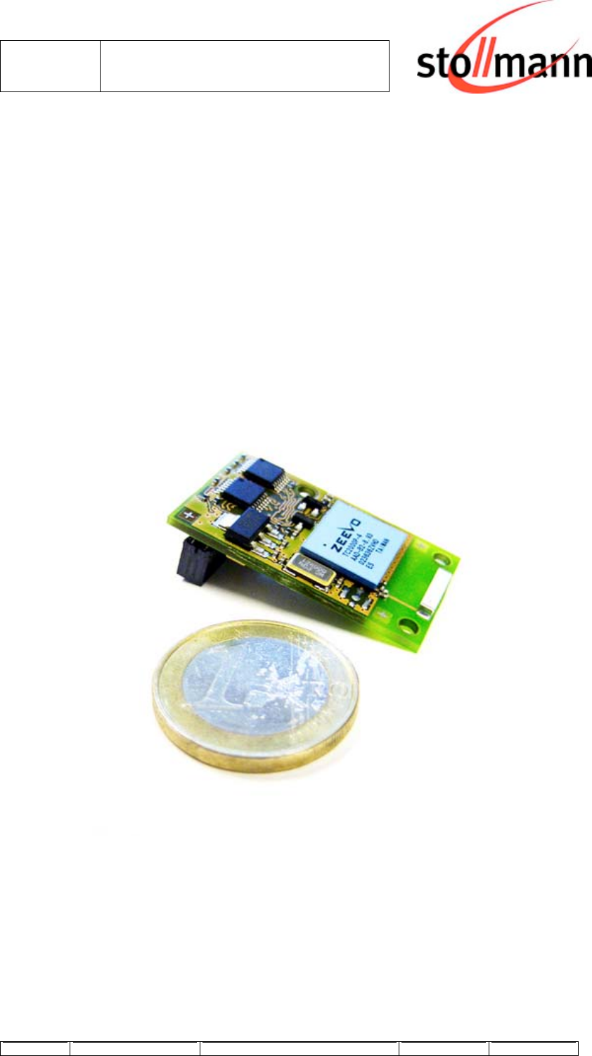
2 Product Description
BlueRS+I connects an asynchronous serial interface with TTL level with the
Bluetooth interface.
2.1 Product Versions
2.1.1 Power Supply
The BlueRS+I is supplied through the double row connector. It can be configured for
5V (default) and 3,3V supply.
2.2 Operation Modes
BlueRS+I runs in three modes:
2.2.1 AT-Mode
The Bluetooth connection is controlled by AT commands of the end device. You
have full control over configuration and initiation of the serial link.
2.2.2 Autoconnect
For some legacy applications or cable replacement, it may be difficult to actively
establish a serial connection before sending the data over the serial link. If you do
not want to program the host device, the BlueRS+I automatically establishes the
serial connection to a previously configured Bluetooth address.
2.2.3 Autoconnect DTR
With the activation of the DTR line, the BlueRS+I Bluetooth connection is set up
automatically. No adaptation of the integrating device is required since the BlueRS+I
is meant to be a transparent serial cable replacement.
Stollmann
E + V GmbH
BlueRS+I
DesignGuide
Author: cl Date of Savin
g
: 19.03.04 Ref: Revision: 1.2 Pa
g
e 5 of 22
2.3 Security
The BlueRS+I supports various security features to restrict access via Bluetooth for
unauthorized devices. These features include device bonding, restricted access via
Bluetooth for bonded devices only and encryption of the transferred data via
Bluetooth link.
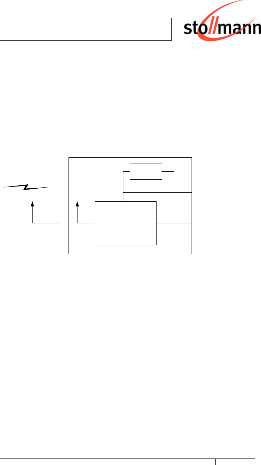
2.4 Block Diagram
Voltage
Regulator
Power Supply
Connector P1
(5 / 3,3V)
serial TTL
BlueRS+I
Bluetooth Chip
External
Antenna
(Option)
Internal
Antenna
Bluetooth
Stollmann
E + V GmbH
BlueRS+I
DesignGuide
Author: cl Date of Savin
g
: 19.03.04 Ref: Revision: 1.2 Pa
g
e 6 of 22
3 Applications
BlueRS+I can be used in different applications. Some typical are described in this
chapter. For application requiring an external adapter please refer to other BlueRS+
versions from Stollmann.
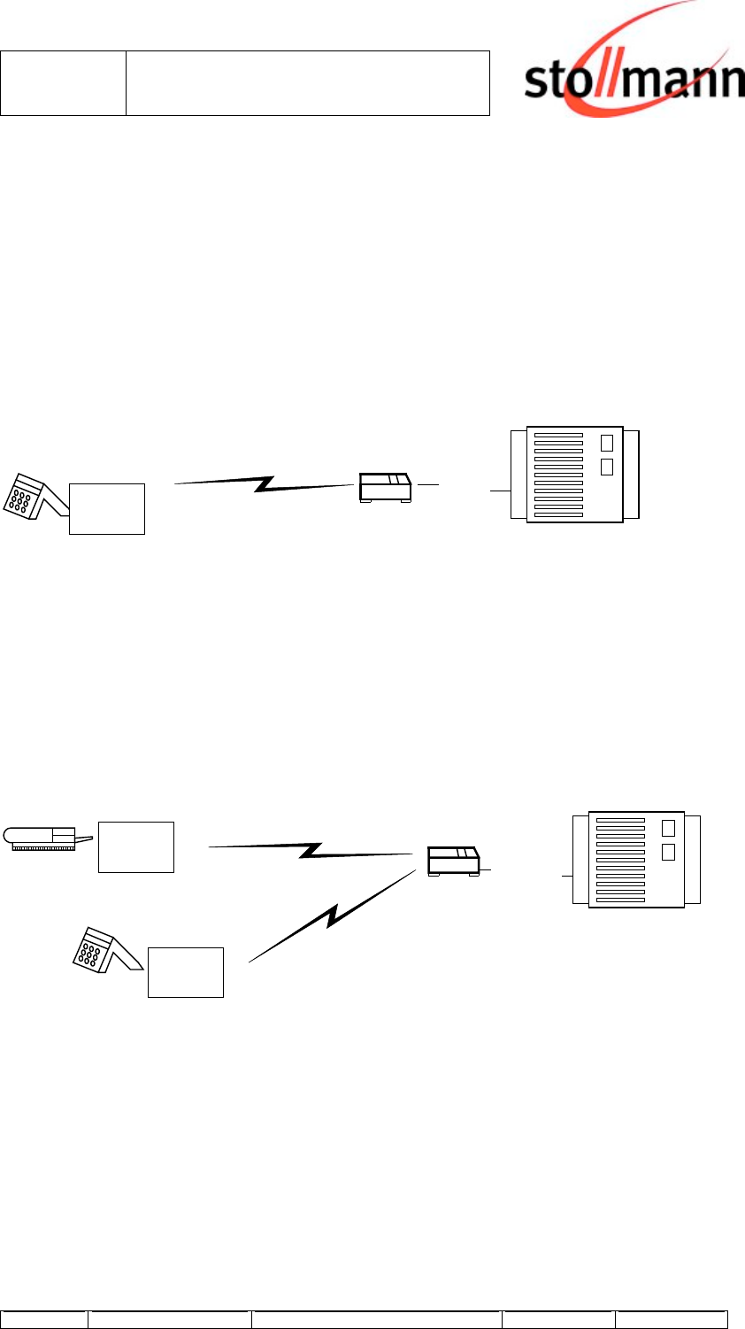
3.1 Cable Replacement Serial Point-to-point
To establish a cable replacement between two devices with a serial interface,
BlueRS+I can be used.
3.2 Cable Replacement Multipoint
Since several devices may be connected with a master device via Bluetooth, several
end devices can also be multiplexed via Bluetooth. This adaptation is shown below
for a desktop device.
In order to handle multiple links a multiplexing protocol is required for the
communication between devices, the BlueRS+ and the host. The BlueRS+ has to be
adapted to the routing scheme of the protocol to transmit the data in an appropriate
way. This includes Bluetooth connection control (i.e. are the Bluetooth links
permanently active or only on demand) and data distribution (i.e. are all data from
the host to be forwarded to all devices or only depending on the address header; are
data from the devices are transmitted to the host transparently or is an address
header to be added). In case you have a multipoint application please contact
Stollmann for specific support.
Bluetooth
RS-232
BlueRS+ Control Unit
BlueRS+I
Bluetooth
Multiplxing
protocol
RS-232
BlueRS+
Control Unit
Device
Bluetooth
BlueRS+I
BlueRS+I
Stollmann
E + V GmbH
BlueRS+I
DesignGuide
Author: cl Date of Savin
g
: 19.03.04 Ref: Revision: 1.2 Pa
g
e 7 of 22
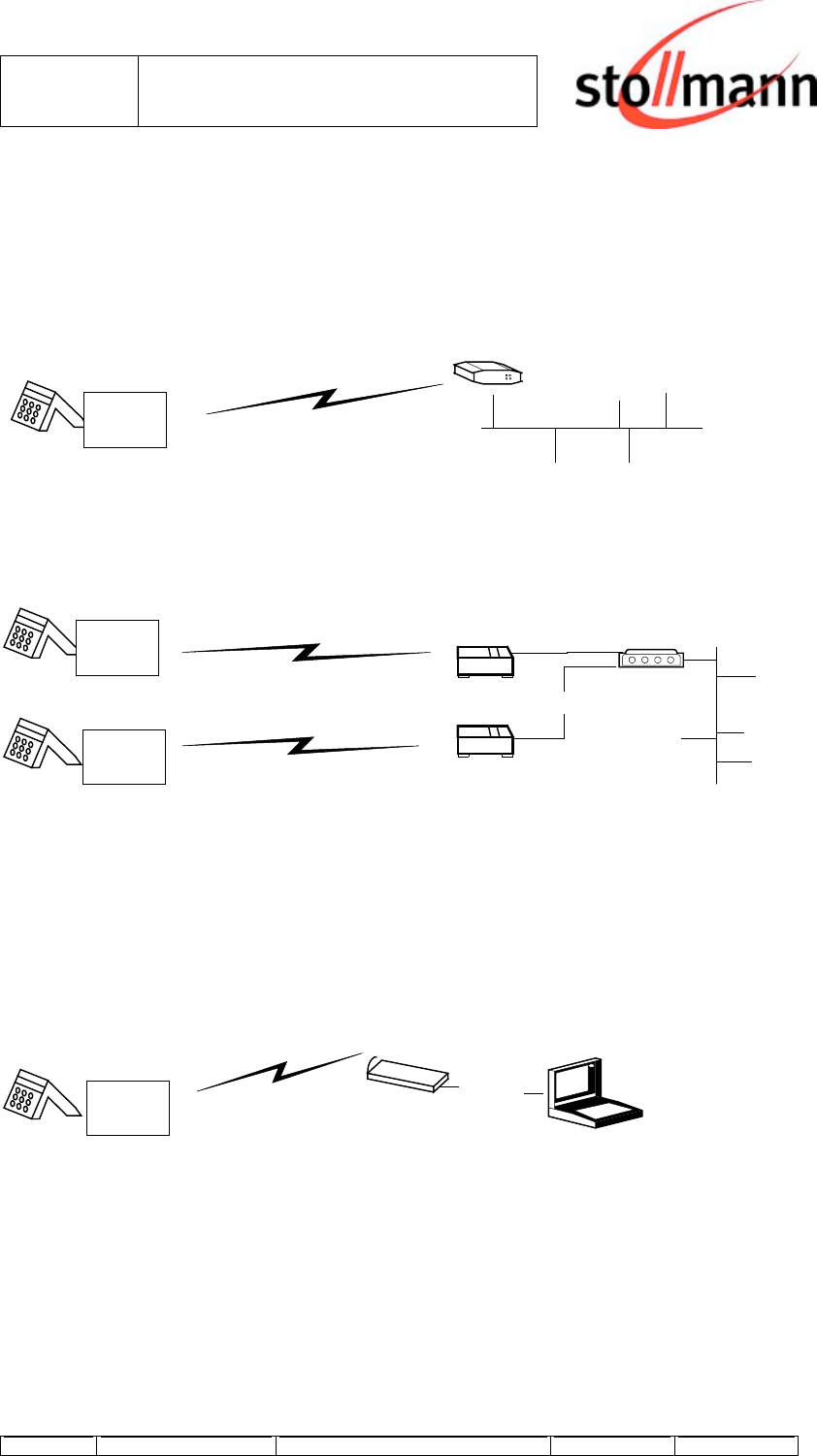
3.3 LAN Access
3.4 Terminal Server
3.5 PC Client
BlueRS+I as Bluetooth Client can establish connections with other Bluetooth
interfaces, e.g. in PCs.
Bluetooth
LAN Access
Point
BlueRS+I
Bluetooth
Terminal
Server
BlueRS+
Bluetooth
RS-232
BlueRS+I
BlueRS+I
Bluetooth
PC
PCMCIA
USB
BluePCMCIA+
BlueUSB+
BlueRS+I

Stollmann
E + V GmbH
BlueRS+I
DesignGuide
Author: cl Date of Savin
g
: 19.03.04 Ref: Revision: 1.2 Pa
g
e 8 of 22
4 Software Interfaces
4.1 AT Commands
Via AT-Commands you may change not only the configuration of BlueRS+I but also
control the Bluetooth connections. The end device must be adapted since a double
connection setup might be required: the first for the Bluetooth connection and the
second for the dial-up link itself. Additionally the Bluetooth-specific configuration
commands must be supported by the end device.
4.1.1 Configuration Commands
A range of parameters can be controlled by configuration commands of BlueRS+I as
listed below:
• Bluetooth Alias Name
• Bluetooth access permission (Security)
• Bluetooth Services
• Passive Scanning capability
• AT/Autoconnect operation mode
• Firmware download
4.1.2 Connection Commands
Command Function Response
AT**BDINQ Scanning the environment for Bluetooth devices OK
AT**BDLIST Displays all found Bluetooth devices OK
ATD Establishes a Bluetooth connection with another
device.
OK or
Connect
ATH Disconnects the Bluetooth Connection. OK
Whenever the Bluetooth connection with a communication partner is established, a
transparent channel for serial data is provided. The Bluetooth link then behaves like
a serial cable.
A detailed description of the AT-Commands is found in the BlueRS+I manual.

Stollmann
E + V GmbH
BlueRS+I
DesignGuide
Author: cl Date of Savin
g
: 19.03.04 Ref: Revision: 1.2 Pa
g
e 9 of 22
4.2 Autoconnect
In case the end device cannot be programmed on the Bluetooth AT Commands or
BlueRS+I should be in fixed operation with another Bluetooth device, the BlueRS+I
Autoconnect can be configured.
Several triggers (i.e. DTR active) may be defined which introduce the scanning
process of the environment and the connection setup with particular Bluetooth
devices.
BlueRS+I then behaves at the interface as a serial cable which is plugged in by
establishing the Bluetooth connection. In case the Bluetooth connection is not being
built up, BlueRS+I is comparable to an unplugged cable.
Trigger Function Parameter
DTR active Bluetooth Connect Bluetooth Address
Power On Bluetooth Connect Bluetooth Address
Transmit data activity Bluetooth Connect Bluetooth Address
Bluetooth link request
(incoming)
accept Bluetooth link none
4.3 Security
Security features are controlled via special AT-commands
brestr defines security level for all incomming BT-links
bcrypt enables/disables data encyption on BT-link
Please refer to the manual for detailed information.
Stollmann
E + V GmbH
BlueRS+I
DesignGuide
Author: cl Date of Savin
g
: 19.03.04 Ref: Revision: 1.2 Pa
g
e 10 of 22
5 Hardware
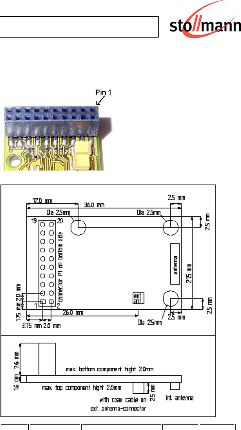
5.1 Dimensions

Stollmann
E + V GmbH
BlueRS+I
DesignGuide
Author: cl Date of Savin
g
: 19.03.04 Ref: Revision: 1.2 Pa
g
e 11 of 22
BlueRS+I Dimensions Europe US
Width 21,5 mm ~0.85 inch
Height 8 mm ~0.3 inch
Length 36 mm ~1.42 inch
Weight ~ 10 g ~ 0.35 oz
Temperature 0...70 Degree Celsius 32...160 Fahrenheit
Humidity 95% Non-Condensing 95% Non-Condensing
5.2 Interfaces, Pin Assignment
The BlueRS+I is connected via the double pin row connector P1. This includes:
• power supply
• serial communication interface (V.24/RS-232 with TTL level)
• reserved general purpose IO pins
5.2.1 Serial Interface
The interface functionally corresponds to the norm V.24 / RS-232 but has TTL-level.
It is compatible to the BlueRS+.
• Transmission speeds 2.400 – 230.400 bps (asynchronous)
• Character representation: 8Bit no Parity, 1 stop bit
7Bit even/odd Parity, 1 stop bit
• half duplex or full duplex
• Flowcontrol hardware (RTS/CTS)
Stollmann
E + V GmbH
BlueRS+I
DesignGuide
Author: cl Date of Savin
g
: 19.03.04 Ref: Revision: 1.2 Pa
g
e 12 of 22
The signal levels are dependent on the supply voltage. The inputs are in any case
5V tolerant. The outputs are supplied as open-drain over 10 kOhm (RxD, CTS) or
100 kOhm (others) by the supply voltage such that the output level is raised to the
supply level. This should be the same on the motherboard to achieve compatibility.
Current sinks should be low-active. 10mA can be driven. It is not possible to drive
LEDs high active directly. Drive LEDs low active or via driver circuitry.
Vcc= 5 V Vcc = 3,3 V
VIH 2,5..5,5 V 2,5..5,5 V
VIL 0..0,8 V 0..0,8 V
VOH
(RxD,CTS)
5 V via 10 kOhm 3,3 V via 10 kOhm
VOH
(all other Outputs)
5 V via 100 kOhm
Imax: -10µA
3,3 V via 100 kOhm
Imax -10µA
VOL 0,55 V @ 10 mA
Imax: +24mA
0,55 V @ 10 mA
Imax: +24mA
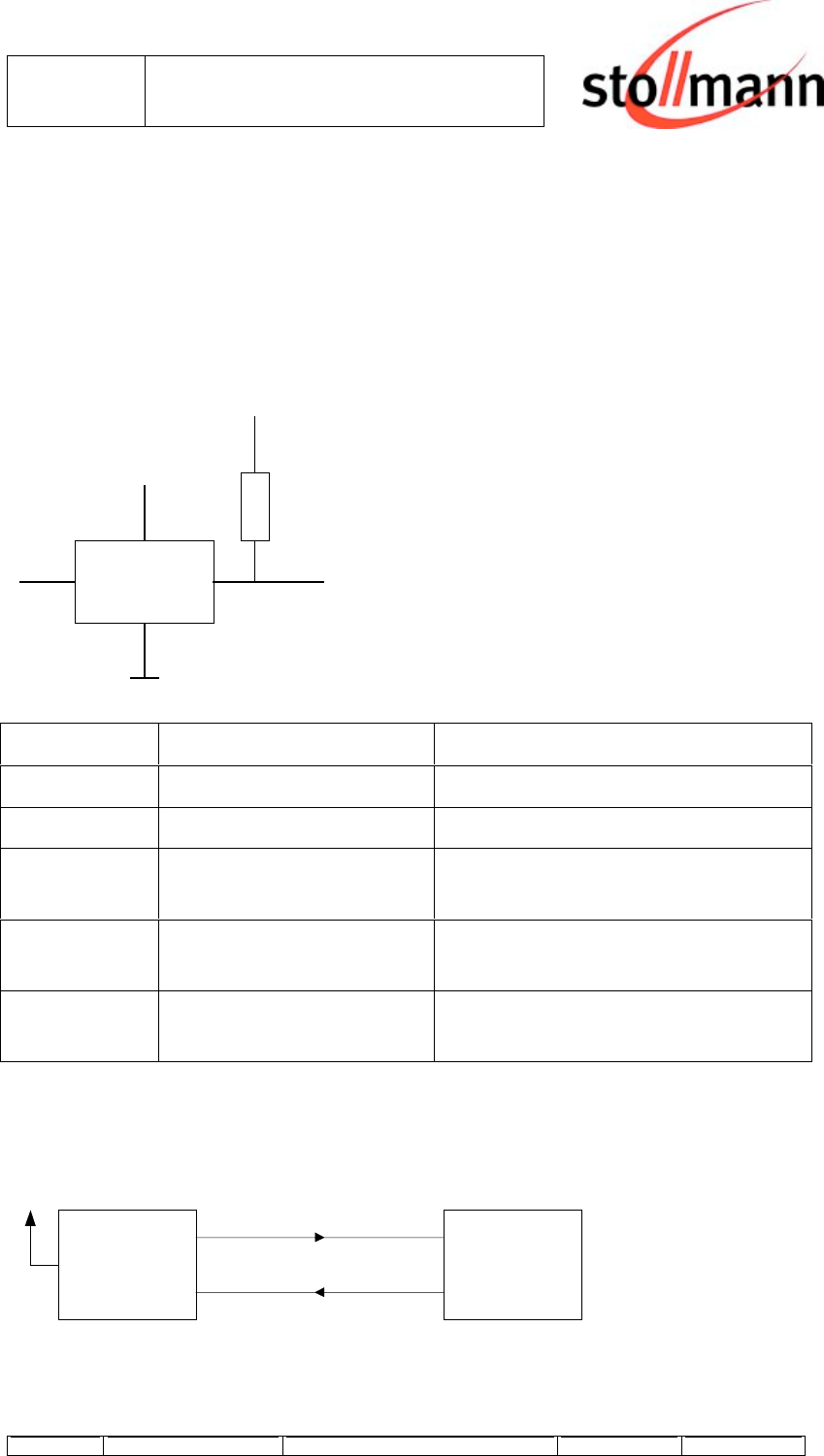
5.2.2 Connector P1
This Connector includes the serial Interface (TTL) and power supply.
Output/Input definition of table below
BlueRS+ Device
Output
Input
Output Circuit
Open Drain
74LVC07
10/100 kOhm
Vcc= 5V or 3,3V
Voh> 0,9 VCC
@ Ioh < - 3 µA
3,3V
Output Circuit

Stollmann
E + V GmbH
BlueRS+I
DesignGuide
Author: cl Date of Savin
g
: 19.03.04 Ref: Revision: 1.2 Pa
g
e 13 of 22
P1 Signal Dir. active BlueRS+I usage
1 GND I - 0V-Power
2 VCC I - +5V / +3.3V -Power
3GNDI-GND
4 TXD I H Transmit Data
5GNDI-GND
6 RXD O H Receive Data
7 reserved
8 RTS~ I L RTS low active
9 reserved
10 CTS~ O L CTS low active
11 RESET~ I L RESET low active
12 DTR~ I L DTR low active
13 reserved
14 DCD~ O L DCD low active
15 RI~ O L RI low active
16 DSR~ O L DSR low active
17 UA O H User Output 1
18 UE~ I L User Input 1
19 UA2 O H User Output 2
20 UE2~ I L User Input 2

Stollmann
E + V GmbH
BlueRS+I
DesignGuide
Author: cl Date of Savin
g
: 19.03.04 Ref: Revision: 1.2 Pa
g
e 14 of 22
5.2.3 Bluetooth Interface
Bluetooth Specification V1.1
RF transmit level 4 dBm (Class 2)
Receiver sensitivity -80 dBm
Range ~10 m
Profiles GAP (General Access Profile)
SDP (Service Discovery Profile)
Serial Port Profile
Dial-up Networking Profile (Option)
LAN-Access Profile (Option)
5.3 Sample interfacing GPIO
It is possible to use the GPIOs on the BlueRS+I pins UEx und UAx. Their behavior
has to be defined project specific in the firmware.
5.4 Layout Guidelines Basic board, Components Requirements
Samtec FCI (Berg)
Pin strip serial P1 MTMM-110-02-S-D-060 86451-106
Stollmann
E + V GmbH
BlueRS+I
DesignGuide
Author: cl Date of Savin
g
: 19.03.04 Ref: Revision: 1.2 Pa
g
e 15 of 22
5.5 Power Supply
There are two variants of supplying power to the BlueRS+I:
• 5 VDC+– 10%, the voltage is regulated on the BlueRS+I (linear regulator). The
regulator is temperature and overcurrent protected.
• 3,3 V +- 2% low noise, the supply voltage is directly used (0 Ohm)
The power supply voltage can be switched as follows. The linear regulator needs to
be replaced by an 0 Ohm resistor.
5.6 Power consumption and power down modes
To reduce power consumption of the BlueRS+I power down modes can be activated
automatically by the BlueRS+ (controlled by parameter settings).
If no Bluetooth connection is established, the following states are implemented, the
activation of these states can be controlled by the parameter bpsm and pwd.
For more details please refer to the BlueRS+I manual.
5.6.1 Deep Sleep state
The Bluetooth RF is completely deactivated, no paging requests from other
Bluetooth devices will be recognized. Only rising control line DTR will activate the
BlueRS+I and may initiate a Bluetooth link dependent on other parameters.
Note: In Deep Sleep state the AT command set is not active, CTS line is low.
5.6.2 Power down state
The Bluetooth RF is activated every 1.25 seconds, paging requests from other
Bluetooth devices will be recognized after that intervals and accepted if allowed.
Additionally rising control line DTR will activate the BlueRS+I and may initiate a
Bluetooth link dependent on other parameters.
Note: In Power down state the AT command set is not active, CTS line is low.
Line regulator 0 Ohm resistor
5 V
supply
3,3 V
supply
Linear regulator IC
removed

Stollmann
E + V GmbH
BlueRS+I
DesignGuide
Author: cl Date of Savin
g
: 19.03.04 Ref: Revision: 1.2 Pa
g
e 16 of 22
5.6.3 Idle state
No power down mode activated.w
All functionality is available immediately including connection control using AT
command set.
5.6.4 Power consumption
The following values are approximate power consumption values in the different
states:
Condition Current Consumption
(3.3V or 5V DC)
Deep sleep ~ 0.7 mA
Power down ~ 2.5 mA
Idle, all functions available, no Bluetooth link ~ 22 mA
Bluetooth connected, no data traffic,
(Master/slave)
~ 24 / 35 mA
Bluetooth connected, data traffic 115 kbit/s ~ 46 mA
5.6.5 Power-up time
The time until the BlueRS+I is able to accept link requests or serial data is about 9
seconds after power-up.
Stollmann
E + V GmbH
BlueRS+I
DesignGuide
Author: cl Date of Savin
g
: 19.03.04 Ref: Revision: 1.2 Pa
g
e 17 of 22
6 Mounting instructions
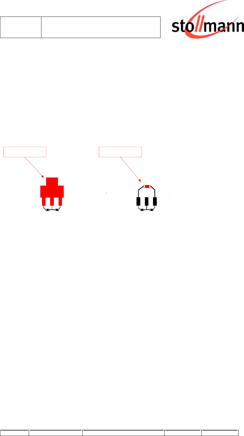
6.1 Antenna Issues
BlueRS+I may be delivered in two antenna designs:
• BlueRS+I comprises an ceramic antenna which as a component is soldered to
the circuit board. This is functional for a BlueRS+I integrated into a plastic
housing. No additional antenna is required.
• For an external antenna to be set in, e.g. because the BlueRS+I is integrated
into a metal housing, the ceramic antenna is replaced by a mini-SMA connector
(50 Ohm technology) . An external antenna can either directly be connected with
this SMA or indirectly by an antenna cable.
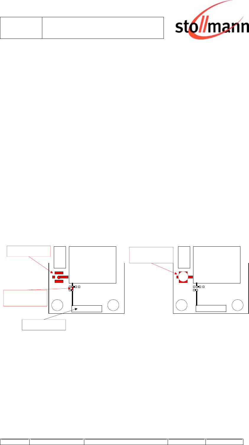
The mini Murata SMD socket for the external antenna may be soldered on the
socket pads. The matching network components connecting the internal antenna
has to be removed.
The influence of the internal antenna resp. the external antenna is in any case to be
checked within the final integration environment. Adjacent PCBs, components,
cable, housings etc. could otherwise influence the radiation pattern.
Zeevo
Socket Pads
Coupling
component
Zeevo
Internal Antenna
Socket for
external antenna
Internal Antenna External Antenna
Stollmann
E + V GmbH
BlueRS+I
DesignGuide
Author: cl Date of Savin
g
: 19.03.04 Ref: Revision: 1.2 Pa
g
e 18 of 22
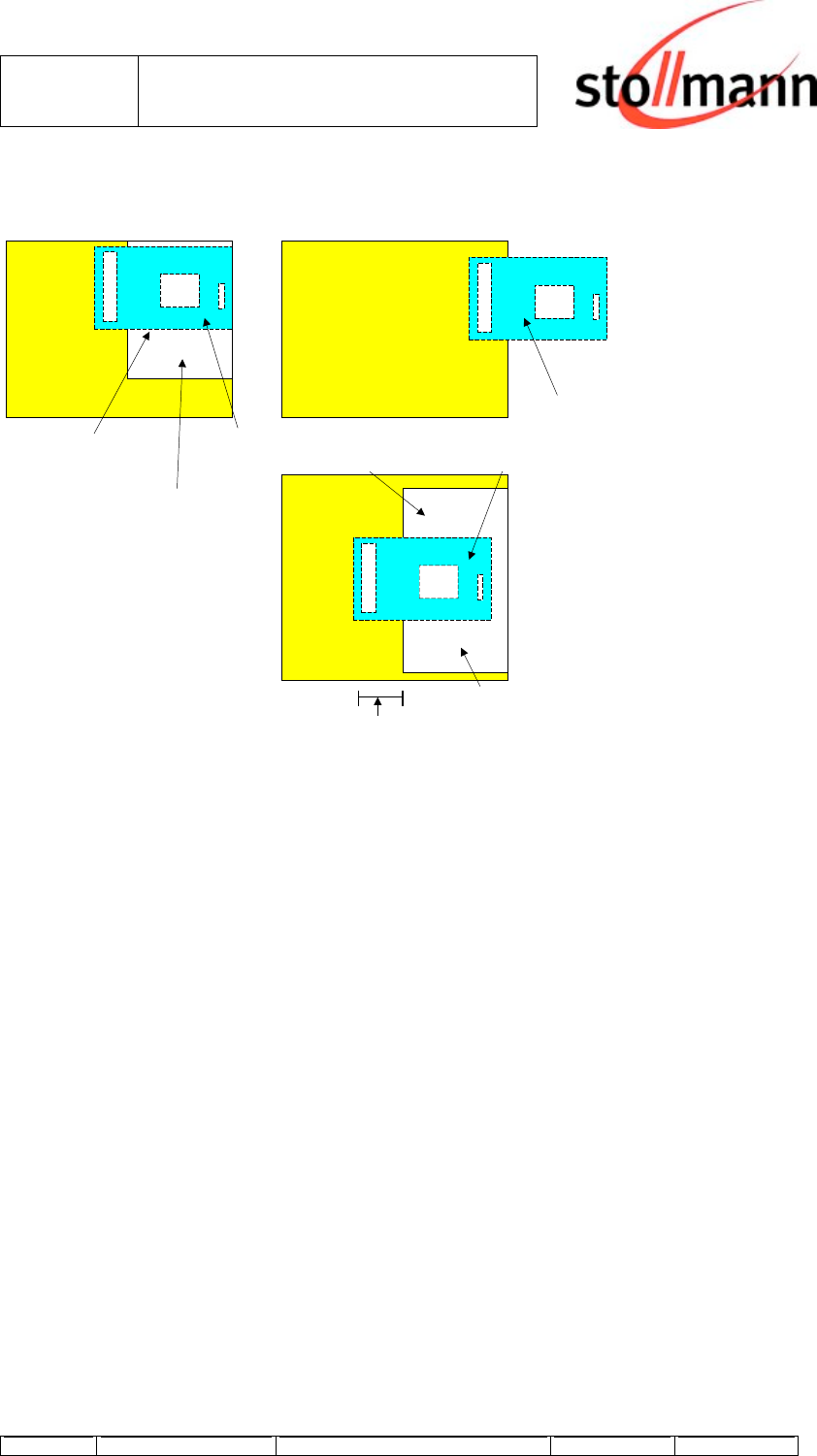
The mother board should have no ground plane under the BlueRS+I to allow best
radiation.
Furthermore there must be a space of at least 15 mm in each direction from the
antenna free from wire, circuits and conductive material.
It must be ensured that the antenna is not co-located or operating in conjunction
with any other antenna or transmitter.
When using an external Antenna the antenna is fixed and connot be removed or
replaced by the enduser.
For detailed consulting on integration please contact Stollmann.
6.2 Housing Guidelines
The individual case must be checked to decide whether a specific housing is
suitable for the use of the internal antenna. A plastic housing must at least fulfill the
following requirements:
• Non-conductive material, non-RF-blocking plastics
• No metallic coating
• ABS is suggested
Spared Ground Plane
Spared Ground Plane BlueRS+I
BlueRS+I
BlueRS+I
Mother Board Mother Board
Mother Board
Space 13 mm
Space 13 mm
Space 10 mm

Stollmann
E + V GmbH
BlueRS+I
DesignGuide
Author: cl Date of Savin
g
: 19.03.04 Ref: Revision: 1.2 Pa
g
e 19 of 22
7 Regulatory Information
7.1 FCC Statement
This device complies with Part 15 of the FCC Rules and with RSS-210 of Industry
Canada.
Operation is subject to the following two conditions:
(1) this device my not cause harmful interference, and
(2) this device must accept any interference received, including interference
that may cause undesired operation.
7.2 Caution
Warning: Changes or modifications made to this equipment not expressly approved
by Stollmann Entwicklungs und Vertriebs may void the FCC authorization to operate
this equipment.
7.3 FCC Warning
This equipment has been tested and found to comply with the limits for a Class B
digital device, pursuant to Part 15 of the FCC Rules. These limits are designed to
provide reasonable protection against harmful interference in a residential
installation. This equipment generates, uses and can radiate radio frequency
energy and, if not installed and used in accordance with the instructions, may cause
harmful interference to radio communications. However, there is no guarantee that
interference will not occur in a particular installation. If this equipment does cause
harmful interference to radio or television reception, which can be determined by
turning the equipment off and on, the user is encouraged to try to correct the
interference by one or more of the following measures:
• Reorient or relocate the receiving antenna.
• Increase the separation between the equipment and receiver.
• Connect the equipment into an outlet on a circuit different from that to which the
receiver is connected.
Consult the dealer or an experienced radio/TV technician for help
The radiated output power of BlueRS+E and BlueRS+I is far below the FCC radio
frequency exposure limits. Nevertheless, the BlueRS+E and BlueRS+I shall be used
in such a manner that the potential for human contact during normal operation is
minimized

Stollmann
E + V GmbH
BlueRS+I
DesignGuide
Author: cl Date of Savin
g
: 19.03.04 Ref: Revision: 1.2 Pa
g
e 20 of 22
7.4 RF-exposure Statement
The BlueRS+I contains a portable modular transmitter. Thus it must have a
separation of at least 2.5 cm between the antenna and the body of the user or
nearby persons, excluding hands, wrists, feet, and ankles.
Any notification to the end user of installation or removal instructions about the
integrated radio module is not allowed.
7.5 Labeling requirements for the End Product
Any End Product integrating the BlueRS+I must be labeled with at least the
following information:
This device contains transmitter with
FCCID: RFR-BRSI / IC: 4957A-BRSI
Stollmann
E + V GmbH
BlueRS+I
DesignGuide
Author: cl Date of Savin
g
: 19.03.04 Ref: Revision: 1.2 Pa
g
e 21 of 22
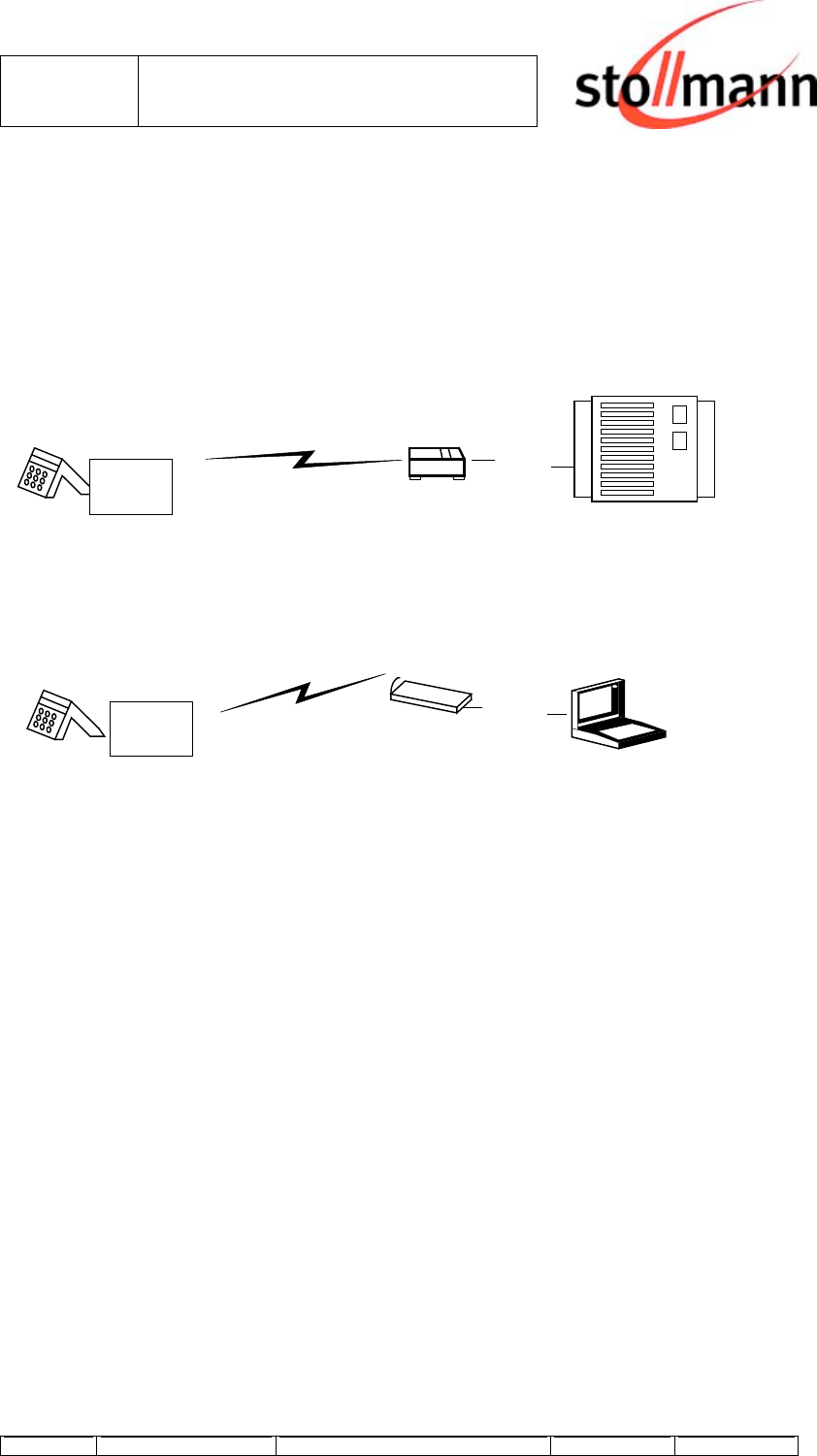
8 Test
8.1 Test Setup
Test Setup cable replacement
Test Setup PC connectivity
Bluetooth
RS-232
BlueRS+ Control Unit
BlueRS+I
Bluetooth
PC
PCMCIA
USB
BluePCMCIA+
BlueUSB+
BlueRS+I

Stollmann
E + V GmbH
BlueRS+I
DesignGuide
Author: cl Date of Savin
g
: 19.03.04 Ref: Revision: 1.2 Pa
g
e 22 of 22
8.2 Compatible Remote Stations
Developer Product Profiles
Stollmann BlueRS+ Serial
Stollmann BlueRS+E Serial
Stollmann BluePCMCIA Serial, Dial-up Networking
Stollmann BlueUSB Serial, Dial-up Networking
Stollmann BlueTA+ Serial, Dial-up Networking
9 Variants of Delivery
Name Class Supply
Voltage
Antenna Art No.
BlueRS+I C2 V5 AI 2 5V Internal 51961
BlueRS+I C2 V5 AE 2 5V External 51963
BlueRS+I C2 V3 AI 2 3,3V Internal 51999
BlueRS+I C2 V3 AE 2 3,3V External 52048