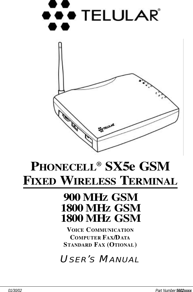
Telular 052651 Desktop PCS Transceiver - Phonecell User Manual 5602xxxx SX5e GSM GPRS Technical Manual
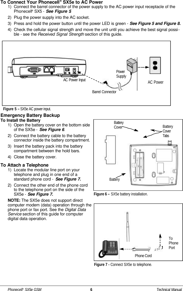
Telular Corporation Desktop PCS Transceiver - Phonecell 5602xxxx SX5e GSM GPRS Technical Manual
Telular >
Contents
- 1. SX5D manual
- 2. SX5e manual
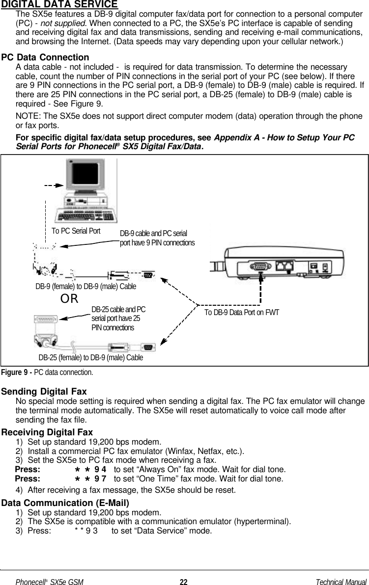
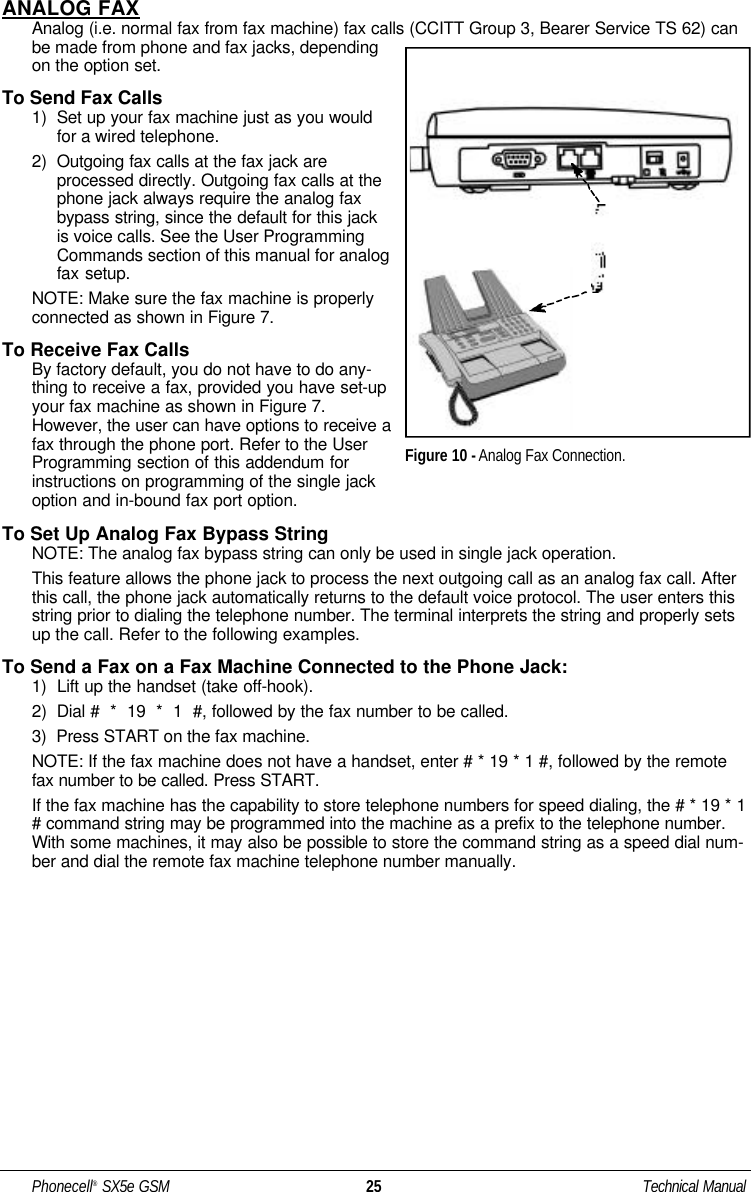
SX5e manual