Telular 052651 Desktop PCS Transceiver - Phonecell User Manual 5602xxxx SX5e GSM GPRS Technical Manual
Telular Corporation Desktop PCS Transceiver - Phonecell 5602xxxx SX5e GSM GPRS Technical Manual
Telular >
Contents
- 1. SX5D manual
- 2. SX5e manual
SX5e manual
01/30/02 Part Number 5602xxxx
P
HONECELL
®
SX5eGSM
F
IXED
W
IRELESS
T
ERMINAL
900 MH
Z
GSM
1800 MH
Z
GSM
1800 MH
Z
GSM
V
OICE
C
OMMUNICATION
C
OMPUTER
F
AX
/D
ATA
S
TANDARD
F
AX
(O
TIONAL
)
U
SER
’
S
M
ANUAL
Phonecell®SX5e GSM 2Technical Manual
Before installing your Phonecell®SX5e, carefully remove the contents from the shipping carton
and check for evidence of shipping damage. If damage is found, contact your Authorized
Telular Distributor or shipping agent immediately.
SAFE OPERATION INSTRUCTIONS
IMPORTANT! Before installing or operating this product, read the SAFETY AND GENERAL
INFORMATION section of this guide.
• Install the unit indoors.
• Install the unit on a hard, flat surface for proper ventilation.
• Do not expose the unit to rain or moisture.
•Do not place the unit on or close to sources of heat.
IMPORTANT NOTICES
TERMS AND CONDITIONS FOR USE OF PHONECELL®PRODUCTS ("Product")
These Terms and Conditions are a legal contract between you and Telular Corporation for the title to and use of the Product.
BY RETAINING AND USING THE PRODUCT AFTER RECEIPT OF IT, YOU AGREE TO THE TERMS AND CONDITIONS
INCLUDING WARRANTY DISCLAIMERS, LIMITATIONS OF LIABILITY AND INDEMNIFICATION PROVISIONS BELOW. IF
YOU DO NOT AGREE TO THE TERMS AND CONDITIONS, DO NOT USE THE PRODUCT AND IMMEDIATELY RETURN
THE UNUSED PRODUCT FOR A COMPLETE REFUND. You agree to accept sole responsibility for any misuse of the Product
by you; and, in addition, any negligent or illegal act or omission of your or your agents, contractors, servants, employees, or
other users of the Product so long as the Product was obtained from you, in the use and operation of the Product. Changes or
modifications not expressly approved by Telular Corporation will void your authority to operate the equipment per FCC part 15
paragraph 15.21.
INDEMNIFICATION OF TELULAR CORPORATION ("TELULAR")
YOU SHALL INDEMNIFY, DEFEND AND HOLD HARMLESS TELULAR FOR ANY OF THE COST, INCLUDING REASON -
ABLE ATTORNEYS' FEES, AND FROM CLAIMS ARISING OUT OF YOU, YOUR CLIENTS' OR OTHER THIRD PARTIES'
USE OR OPERATION OF THE PRODUCT: (i) FOR MISUSE OR IN A MANNER NOT CONTEMPLATED BY YOU AND
TELULAR OR INCONSISTENT WITH THE PROVISIONS OF THIS MANUAL; (ii) IN AN ILLEGAL MANNER OR AGAINST
PUBLIC POLICY; (iii) IN A MANNER SPECIFICALLY UNAUTHORIZED IN THIS MANUAL; (iv) IN A MANNER HARMFUL
OR DANGEROUS TO THIRD PARTIES; (v) FROM CLAIMS BY ANYONE RESPECTING PROBLEMS, ERRORS OR MIS-
TAKES OF THE PRODUCT; OR (vi) COMBINATION OF THE PRODUCT WITH MATERIAL, MODIFICATION OF THE
PRODUCT OR USE OF THE PRODUCT IN AN ENVIRONMENT NOT PROVIDED, OR PERMITTED, BY TELULAR IN
WRITING. THE PARTIES SHALL GIVE EACH OTHER PROMPT NOTICE OF ANY SUCH COST OR CLAIMS AND COOP-
ERATE, EACH WITH THE OTHER, TO EFFECTUATE THIS INDEMNIFICATION, DEFENSE AND HOLD HARMLESS.
PLEASE SEE THE IMPORTANT NOTICES SECTION OF THIS GUIDE FOR IMPOR -
TANT INFORMATION ON USE, WARRANTY AND INDEMNIFICATION
CONTENTS
Telular Corporation
Corporate Headquarters
647 North Lakeview Parkway
Vernon Hills, Illinois 60061, USA
Technical Support
Tel: 847-247-9400 · Fax: 847-247-0021
E-mail: main office@telular.com · http://www.telular.com
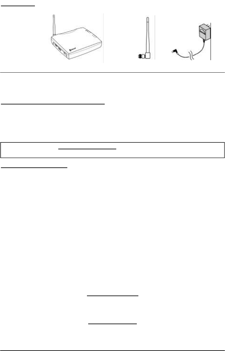
Power SupplyPhonecell®SX5e CDMA FWT Spike Antenna
Part Number 56023001 ©2002 Telular Corporation, All Rights Reserved

Phonecell®SX5e GSM 3Technical Manual
TABLE OF CONTENTS
Contents ........................................................................................................................2
Safe Operation Instructions ........................................................................................2
Important Notices ........................................................................................................ 2
Installation.......................................................................................................................
Location and Setup ......................................................................................................
Optional Wall-Mount Instructions .................................................................................
Connect Your Phonecell®SX5 to AC Power...................................................................
Emergency Battery Backup .........................................................................................
Plug in Your Telephone ................................................................................................
Phonecell®SX5 Operation .............................................................................................
How to Use the LED Status Indicators ........................................................................
How to Place a Call .....................................................................................................
How to Receive a Call .................................................................................................
How to End a Call........................................................................................................
The Hookflash Function...............................................................................................
Important Tones and Alerts ..........................................................................................
Supplementary Features (Network Dependent) ..........................................................
Call Waiting ..................................................................................................................
Three-Way Calling........................................................................................................
Call Forwarding............................................................................................................
Caller ID .......................................................................................................................
Voice Mail Service........................................................................................................
Digital Data Service ........................................................................................................
PC Data Connection ....................................................................................................
Sending Digital Fax......................................................................................................
Receiving Digital Fax ...................................................................................................
Data Communication (E-Mail)......................................................................................
Browsing the Internet...................................................................................................
Analog (Group 3) Fax Service (Optional) ..........................................................................
Plug In A Fax Machine .................................................................................................
Sending A Fax..............................................................................................................
Receiving A Fax ...........................................................................................................
Phonecell®SX5 Programming.......................................................................................
Programming Mode Overview .....................................................................................
How to Adjust Voice Volume ........................................................................................
How to Change the Lock Code ....................................................................................
How to Restrict Outgoing Calls....................................................................................
How to Set the Alarm ...................................................................................................
How to Disable the Alarm ............................................................................................
How to Set Caller ID Mode ..........................................................................................
How to Set 1 Minute Alert Beep...................................................................................
How to Set the Connecting Tone .................................................................................
How to Reset the Terminal ...........................................................................................
Phonecell®SX5 Technician Programming ...................................................................
Phonecell®SX5 Troubleshooting ..................................................................................
General Information and Safety ....................................................................................
Warranty ..........................................................................................................................
Appendix A: How to Setup PC Serial Ports for Phonecell®SX5
Computer Digital Fax/Data .........................................................................................
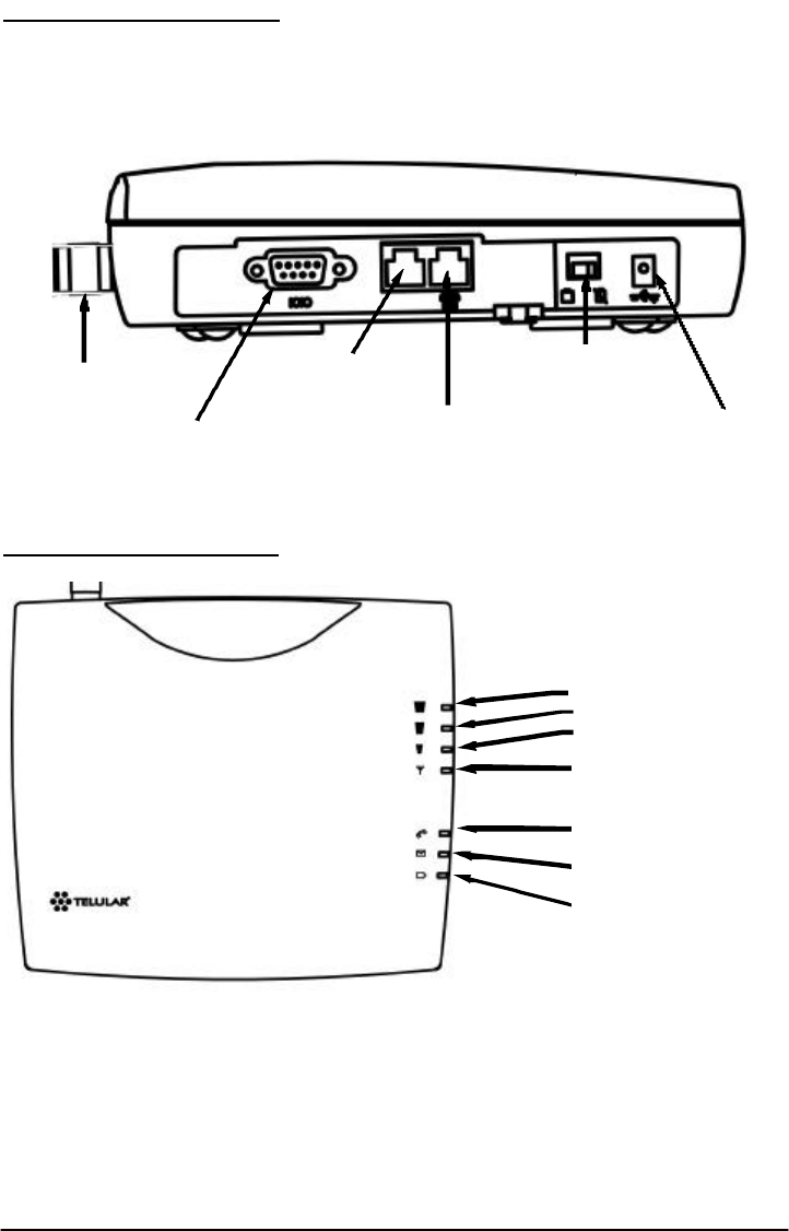
EXTERNAL CONNECTERS
LED STATUS INDICATORS
Phonecell®SX5e GSM 4Technical Manual
RSSI 3
RSSI 2
RSSI 1
Service Indicator
Hook Indicator
Message Indicator
Power/Battery
Antenna
(TNC)
Serial Port
(DB-9)
Fax or PSTN
(RJ-11)
Phone
(RJ-11))
AC/Battery Switch
AC Power Input
Phonecell®SX5e GSM 5Technical Manual
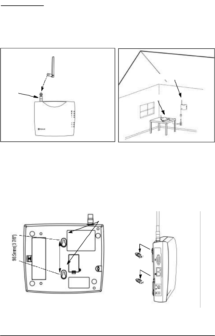
INSTALLATION
Location and Setup
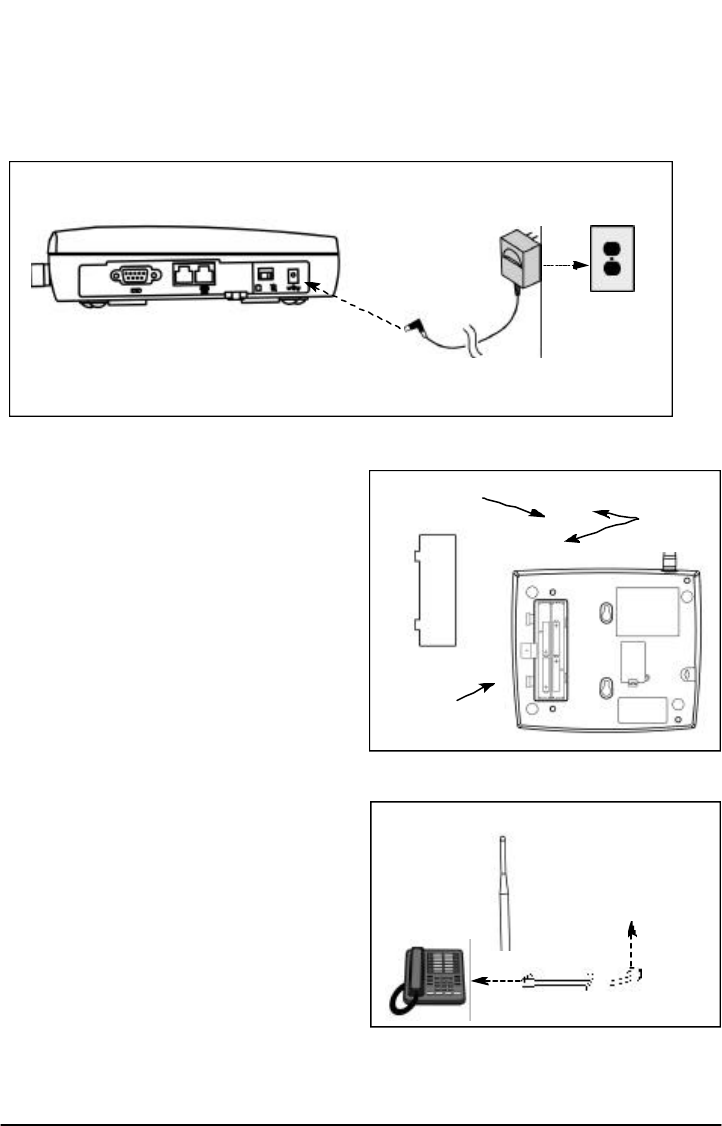
The Phonecell®SX5 comes with a standard spike antenna (TNC). For optimal signal strength,
choose a location that is above ground and as close to windows (or exterior walls) as possible -
See Figure 2. Cellular signal strength is displayed by the Received Signal Strength Indicator
(RSSI) LED on the unit - See the How to Use the LED Status Indicators section of this guide.
1) Connect the antenna to the side of the terminal - see Figure 1.
2) Finger-tighten the antenna; do not over-tighten.
To Wall-Mount the SX5e
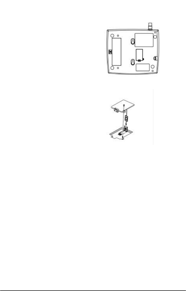
1) Mark two hole locations 98.5mm (3-7/8 inches) vertically apart and drill two holes into the
wall.
2) Install the screws (not supplied) into the wall, leaving a gap (approximately 3 mm (1/8 inch))
between screw head and wall.
3) Align the mounting holes with the screws and mount the Phonecell®SX5 onto the screws -
See Figures 3 and 4.
Figure 2 – For optimal call clarity, the antenna should
be pointed up and the SX5e located close to an exterior
wall or window.
Wall-Mount
Figure 1 –
SX5e antenna connection.
Spike
antenna
Figure 3 –SX5e mounting holes. Figure 4 – Mount the SX5e on screws.
TNC Antenna
Connector
Mounting Holes
Table Mount
Phonecell®SX5e GSM 6Technical Manual
To Connect Your Phonecell
®
SX5e to AC Power
1) Connect the barrel connector of the power supply to the AC power input receptacle of the
Phonecell®SX5 - See Figure 5.
2) Plug the power supply into the AC socket.
3) Press and hold the power button until the power LED is green - See Figure 5 and Figure 8.
4) Check the cellular signal strength and move the unit until you achieve the best signal possi-
ble - see the Received Signal Strength section of this guide.
Emergency Battery Backup
To Install the Battery
1) Open the battery cover on the bottom side
of the SX5e - See Figure 6.
2) Connect the battery cable to the battery
connector inside the battery compartment.
3) Insert the battery pack into the battery
compartment between the hold bars.
4) Close the battery cover.
To Attach a Telephone
1) Locate the modular line port on your
telephone and plug in one end of a
standard phone cord - See Figure 7.
2) Connect the other end of the phone cord
to the telephone port on the side of the
SX5e - See Figure 7.
NOTE: The SX5e does not support direct
computer modem (data) operation through the
phone port or fax port. See the Digital Data
Service section of this guide for computer
digital data operation.
Battery
Cover
Tabs
Figure 6 – SX5e battery installation.
Battery
Cover
Battery
Figure 7 - Connect SX5e to telephone.
Phone Cord
To
Phone
Port
Figure 5 –
SX5e AC power input.
AC Power
Power
Supply
Barrel Connector
AC Power Input

Phonecell®SX5e GSM 7Technical Manual
PHONECELL SX5E OPERATION
To Use the LED Status Indicators
1) Power-on the unit (see the Connect Your Phonecell ®to AC Power section of this manual).
2) The LED indicators on the front of the SX5e will turn ON. The following tables describe the
modes and operation of the indicators.
Received Signal Strength Indicator LED’s
LED Activity Cellular Signal Strength
1Flashing Lowest
Continuous Poor
2Flashing Ok
Continuous Good
3Flashing Very Good
Continuous Best
Service Indicator LED
LED Color LED Activity Description
Green Continuous Full Service
Amber Continuous Limited Service
Red Continuous No Service
Flashing SIM Error
Hook Indicator LED
LED Color LED Activity Description
Green Flashing (with ringer) Incoming call
Continuous FWT is off hook
Fast Flashing Processing data call
Slow Flashing Call on hold
Message Indicator LED
LED Color LED Activity Description
Green Continuous New voicemail message
Slow Flashing New text message
Power/Battery
LED Color LED Activity Description
Green Continuous Power supply applied
Amber Continuous Battery power active
(battery switch on)
Red Continuous Battery low (battery switch
on)
Slow Flashing Batter low (power supply
applied
To Install the SIM
Card
The GSM module within the Phonecell®SX5 requires a Subscriber Identification Module (SIM)
for normal operation. The service provider supplies a SIM card, which carries the account infor-
mation needed to operate the Phonecell®SX5. The mini-SIM compartment is on the back of the
Phonecell®SX5 - see Figure 11.
1) Disconnect DC power.
2) Remove the SIM compartment cover by
removing the screw.
3) Open the SIM card holder.
4) Line up the mini-SIM card with the arrow on
the SIM card holder.
5) Gently insert the mini-SIM card in the slot of
the SIM card holder - See Figure 12.
6) Close the SIM card holder.
NOTE: If you insert the SIM card improperly, the
holder will not close. Do not force it shut. Make
sure the SIM card is aligned properly with the
directional arrow on the holder.
7) Reattach the SIM compartment cover with the
screw.
8) Reconnect DC power.
The mini-SIM may require entry of a Personal
Identification Number (PIN). The PIN is a four- to
eight-digit number provided with the SIM card. If
the service provider has set the SIM to require
PIN entry, the Phonecell®SX5 will request the
PIN each time it is powered ON or the SIM is
removed and replaced. The PIN can be stored
within the Phonecell®SX5 for automatic entry when required. To use the automatic PIN entry
feature, the PIN must be correctly programmed and automatic PIN entry must be enabled.
If PIN entry is requested while automatic PIN entry is disabled, the Phonecell®SX5 emits a SIM
Inactive tone. The SIM PIN can be manually entered at that time by dialing the PIN and press-
ing #. If entry is successful, the SIM Inactive tone will be replaced by service dial tone.
To Enable/Disable the Automatic PIN Entry Feature
1) Using a POTS (Plain Old Telephone Set) phone connected to the telephone port, lift up the
handset (take off-hook).
NOTE: You must have tone-dial (DTMF) capability to enable/disable the Automatic PIN Entry
Feature.
2) Enter the Programming mode:
Press: # * 0 * 1 2 3 4 5 6 7 8 #
The dial tone will cease upon entry of the first digit. If you enter the access code correctly, the
dial tone should change to a different, steady Programming tone and the bottom LED indicator
on the front of the Phonecell®SX5 will blink alternately RED and GREEN to indicate that you’re
in the programming mode.
3). Once in Programming mode:
Press: # * 65 * < auto_PIN> * <PIN> #
• To disable automatic PIN entry, set the "auto PIN" value to 0.
• To enable automatic PIN entry, set the "auto PIN" value to 1.
You must enter either 0 or 1, otherwise, the FWT will not update or store this value and the
existing stored parameter will remain. The factory default value is 0 (disabled). The factory
default PIN setting within the FWT’s non-volatile memory is "1234."
4) Correct entry will be confirmed by the return of the programming tone, which
signifies that the unit is ready to accept the next entry. Incorrect entry will result in a short,
three tone sequence of rising frequencies, followed by the return of the programming tone,
which again signifies that the unit is ready to accept the corrected entry.
Phonecell®SX5e GSM 8Technical Manual

5) Hang up the telephone handset (place on-hook).
For Example: To enable automatic PIN entry for PIN "1234," dial: # * 65 * 1 * 1234 #
Phonecell®SX5e GSM 9Technical Manual

To Change the PIN Value Entered by the Automatic PIN Entry Feature
Automatic PIN entry must be disabled when youl program the new PIN and Auto PIN Entry.
1) Using a tone-dial (DTMF) POTS telephone connected to the Phone port, lift up the
handset(take off-hook).
2) Enter the Programming mode:
Press: # * 0 * 1 2 3 4 5 6 7 8 #
The dial tone will cease upon entry of the first digit. If you enter the access code correctly, the
dial tone should change to a different, steady “Programming” tone and the bottom LED indicator
on the front of the Phonecell®SX5 will blink alternately RED and GREEN to indicate that you’re
in the programming mode.
3) Press: # * 64 * < old_PIN> * <new PIN> * <new PIN> #
The new SIM PIN will be supplied by the service provider with a new SIM.
If the SIM card is changed, the PIN must be reprogrammed using the above command with the
correct new PIN for the new SIM.
NOTE: The factory default PIN setting within the FWT’s non-volatile memory is "1234."
4) Correct entry will be confirmed by the return of the programming tone, which signifies that
the unit is ready to accept the next entry. Incorrect entry will result in a short, three tone
sequence of rising frequencies, followed by the return of the programming tone, which again
signifies that the unit is ready to accept the corrected entry.
5) Hang up the telephone handset (place on-hook).
For Example: To set up a new SIM with PIN "5678," dial: # * 64 * 1 2 3 4 * 5 6 7 8 * 5 6 7 8
#
NOTE: This procedure will not change the PIN encoded on the SIM. It will only change the PIN
stored in the FWT for automatic entry of the PIN when requested by the GSM module.
If the SIM card in use has SIM PIN Entry enabled, it is strongly recommended that Automatic
PIN Entry be selected.
To Set a New PIN in the SIM
REMINDER: Automatic PIN entry must be disabled - before and while the SIM PIN is changed -
until programming of the new PIN and Auto PIN Entry (see previous page) is completed.
1) Using a tone-dial (DTMF) POTS telephone connected to the Phone port, lift up the handset
(take off-hook).
2) Press: * * 04 * < old_PIN> * <new_PIN> * <new_PIN> #
NOTE: You must know the old PIN to change it and the new PIN must be 4 to 8 digits (0 - 9) in
length.
3) Incorrect entry of the old PIN will be indicated by a short, three tone sequence of rising fre-
quencies. Hang up the telephone handset and start over at step 1 with the correct old PIN.
Incorrect length (less than 4 or more than 8 digits) of the new PIN or not entering the same
value in both new PIN entries will result in silence. Hang up the telephone handset and start
over at step1.
Correct entry will be confirmed by a short beep. Hang up the telephone handset.
For Example: To set up a new SIM with PIN "5678," where the old PIN is “1234,” dial: * * 04
* 1 2 3 4 * 5 6 7 8 * 5 6 7 8 #
NOTE: In case of PIN2, substitute the following step 2:
2) Press: * * 042 * <old_PIN2> * <new_PIN2> * <new_PIN2> #
NOTE: You must know the old PIN2 to change it and the new PIN2 must be 4 to 8 digits (0 - 9)
in length.
For Example: To set up a new SIM with PIN2 "5678," where the old PIN2 is “1234,” dial: * *
042 * 1 2 3 4 * 5 6 7 8 * 5 6 7 8 #
NOTE: This procedure will change the PIN encoded on the SIM. It will not change the PIN
stored in the FWT for automatic entry of the PIN when requested by the GSM module. (See pre-
vious page for instructions on how to enter the auto-entry PIN value).
Phonecell®SX5e GSM 10 Technical Manual

Phonecell®SX5e GSM 11 Technical Manual
To Unblock a SIM PIN
Use the following key sequence to unblock a SIM card:
1) Press: * * 05 * <PIN_unblocking key> * <new_PIN * <new PIN> #
2) Press: * * 052 * <PIN2_unblocking key> * <new_PIN2 * <new PIN2> #
NOTE: This procedure will change the PIN encoded on the SIM. It will not change the PIN
stored in the FWT for automatic entry of the PIN when requested by the GSM module. (See pre-
vious page for instructions on how to enter the auto-entry PIN value).
To Place a Call
1) Pick up your telephone handset (your phone is now “off-hook”).
2) Listen for dial tone (If service is not available, a No-Service tone is produced. Hang-up the
phone and try again. If the No-Service tone continues, contact your service provider to make
sure cellular service is activated.).
3) Dial the phone number.
To Receive a Call
When your telephone rings, pick up the handset and begin talking.
How to End a Call
Hang-up the phone (place the handset back onto the telephone cradle).
The Hookflash Function
When you initiate the Hookflash function, it automatically lets you:
Speed up the connection after you dial a phone number.
Answer an incoming call that occurs when you’re dialing a phone number.
Use special (supplementary) cellular services which may be available in your cellular service
area (see the Using Standard Supplementary Services section of this manual).
Tto Use the Hookflash Function
Depending upon your phone, there are two ways to initiate the Hookflash function:
Press the dedicated “HOOKFLASH” or “FLASH” key on your telephone.
Press the hang-up or switch-hook mechanism on your phone once quickly (approximately 1/2-
second).
Important Tones and Alerts
No-Service Tone – When cellular service is not available, the receiver emits a No-Service (fast-
beeping) tone instead of the normal (steady) dial tone.
ROH (Receiver Off-Hook) Tone – If the telephone equipment remains off-hook (off its cradle)
with no dialing activity for 45 seconds, the receiver emits an ROH tone for 60 seconds.
Incoming Call Alert – If you’re dialing a number and an incoming call occurs, the receiver will
emit an audible ring. To answer the incoming call:
Press the “HOOKFLASH” button once. This will connect the incoming call.
OR hang-up immediately. This will cause the phone to start ringing.
Supplementary Service Dial Tone – When supplementary services are enabled and active, the
receiver may emit a special dial tone to indicate that one or more services are active.
Roam Dial Tone – When cellular service is available, but the Phonecell®SX5 is in a Roam area,
the receiver may emit a different dial tone to indicate the roaming condition. However, unless
the FWT is re-programmed in the field, the factory default tone is set the same as normal serv-
ice dial tone.
Non-Registered Service Tone – When the SIM Card is inactive, missing from the Phonecell®
SX5, or installed but requires PIN entry, the receiver emits a
non-registered service tone instead of the normal (steady) dial tone.

How to Use Call-Dependent Supplementary Services
Call-dependent supplementary services are those services handled within an active call. These
features are network-dependent. Check with your cellular provider to determine available fea-
tures.
Use the following commands to activate the call-dependent supplementary services:
NOTE: <send> is provided by the hookflash function (See the Hookflash Function section of
this manual).
To Release All Held Calls or Set User Determined User Busy For a Waiting Call:
Press: 0 <send>.
To Release All Active Calls and Accept the Held/Waiting Call:
Press: 1 <send>.
To Release a Specific Active Call x:
Press: 1 x <send> (x represents the call ID 1-7).
To Place All Active Calls on Hold and Accept the Held/Waiting Call:
Press: 2 <send>.
To Place All Active Calls on Hold Except Call x:
Press: 2 x <send> (x represents the call ID 1-7).
To Add a Held Call to the Conversation:
Press: 3 <send>.
To Place All Active Calls on Hold and Make the Call to the Specified Phone Number:
Press: PhoneNo <send>.
NOTE: When both a held and a waiting call exist in a conflicting situation, the above proce-
dures apply to the waiting call.
Call Waiting:
Permits a subscriber to be notified of an incoming call while the subscriber is engaged in an
active or held call. The subscriber can either accept, reject, or ignore the incoming call.
Activate: * 43 #
Deactivate: # 43 #
Interrogate: * # 43 #
Call Hold:
Allows a served subscriber, who is provisioned with this supplementary service, to interrupt
communication on an existing active call and then subsequently, if desired, re-establish commu-
nication. The traffic channel remains assigned to the subscriber after the communication is inter-
rupted to allow origination or possible termination of other calls.
To Adjust the Volume Level
If the volume level on your phone is too high or too low, you can adjust the levels using the key-
pad on your telephone. Note: your telephone must be in Tone-Dial (DTMF) mode to adjust the
levels.
To Increase Audio Level - Increase the audio level in steps by pressing:
# * 8 (also known as # * Up)
Continue to press # * 8 until the desired level is reached.
To Decrease Audio Level - Decrease the audio level in steps by pressing:
# * 3 (also known as # * Down)
Continue to press # * 3 until the desired level is reached.
NOTE: The default setting lets you adjust the audio up to three (3) steps from the default vol-
ume in either direction (Up or Down). The volume setting remains in effect for future calls until
changed manually, even if the telephone is on-hooked. If the Phonecell®SX5 power is cycled
(turned OFF/ON), the default mid-range volume setting will be restored.
Phonecell®SX5e GSM 12 Technical Manual

Variable Dial Time (Auto SEND Delay) Option
When you place a call, your Phonecell®SX5 automatically sends the phone
number over the cellular network after you dial the last digit – just like a landline phone.
However, to make sure you have enough time to dial the last digit, a 3-second Auto SEND
Delay is programmed into the unit at the factory. To change the Auto SEND Delay setting, see
the How To Set the Auto SEND Delay section of this manual.
Data After SEND (In-Call DTMF Signaling) Option
Depending upon your cellular provider, the Data After SEND option may need to be Enabled or
Disabled to use special cellular features such as call waiting, three-way conference calls, voice
mail, etc. Please consult your service provider for the required Data After Send/In-Call DTMF
Signaling configuration.
The factory default setting is 0 (In-Band Signaling only). To change the Data After SEND setting,
see the How To Set Data After SEND (In-Call DTMF Signaling) section of this manual.
Zero Dial Delay for Frequently Called Numbers
A new patented feature enables the Phonecell®SX5 to recognize your frequently called phone
numbers and send them immediately–without the 3-second Auto SEND Delay. The Phonecell®
SX5 stores a list of up to 50 numbers in its memory. This list contains any number that you’ve
called at least twice successfully.
NOTE: Cycling (turning OFF/ON) the power will erase the current list. A new list will be started
when power is re-applied. To enable or disable this feature, see the Enable/Disable Zero Dial
Delay for Frequently Called Numbers section of this manual.
Caller ID Format
The Phonecell®SX5 will support Caller ID device operation. The FWT factory default format is
designed to work for most Caller ID devices. If the Caller ID device does not respond, then
change the FWT Caller ID format using the programming command below. The Phonecell®SX5
can be programmed with an ordinary touch-tone telephone.
NOTE: The User Programming mode is not accessible during a call. Refer to
the Phonecell®SX5 Programming section of this manual to enter the Programming Mode.
To Enter Caller ID Format
The following key sequence is used to select the Caller ID format:
Press # * 84 * <CID format> #
The Caller ID Format factory default value will work for most Caller ID devices. If the Caller ID
device does not respond, program a value of 1 in the "CID Format" field. If the Caller ID device
still does not respond, then program a value of 2. If the value is not in the range 0 to 2, it is con-
sidered invalid and the FWT will not update or store this value; the currently stored value will
remain. The factory default value is 0.
When the FWT is programmed to Format 0, date and time information is not provided by the
FWT. When the FWT is programmed to Format 1 or Format 2, the FWT provides "January 1,
Midnight" as generic time and date information. The actual display of this generic date and time
("January 1, Midnight") will vary as it is determined by the Caller ID device.
For Caller ID Devices with Date and Time Display
When the Caller ID device is first powered, the date and time information will begin from
"January 1, Midnight." The user cannot change the date and time through the FWT.
When the Caller ID format is set to factory default 0, date and time will continue to advance.
Each incoming call will not affect the date and time.
When the Caller ID format is set to either 1 or 2, the date and time will be reset to "January 1,
Midnight" for each incoming call.
Phonecell®SX5e GSM 13 Technical Manual

Using Standard Supplementary Services
Your Phonecell®SX5 is compatible with a variety of special services, including:
Call Forwarding
Call Barring
Call Waiting
Three-Way Calling
Caller ID
Voice Mail
and more...
Depending upon your cellular provider, these services may be available on a
subscription basis. However, certain dialing sequences must be entered. Please consult your
service provider for the dialing instructions for your system.
Standard supplementary services are defined as those supplementary services handled while
not in a call. Depending on the supplementary service, several commands may be available.
The command list is defined below:
Registration - The programming by the user of information to enable subsequent operation of a
service. This action involves input of specific supplementary information. For example, when
call-forwarding registration is initiated by the user, a forwarding number must be supplied.
Erasure - The deletion of information stored against a particular service by a previous registra-
tion.
Activation - An action taken by the FWT user to enable a previously registered process to run.
Deactivation - An action taken by the FWT user to terminate the process started at activation.
Depending on the supplementary service, additional parameters may be required to successfully
complete an operation, such as phone number or password. Some supplementary services
have optional parameters, such as Teleservice and/or Delay settings. Delay is the amount of
time to wait before completing performance of a service that has a condition controlling its activi-
ty; for example, call forward on no answer waits an amount of time equal to the "delay" for the
phone to be answered before declaring no answer and forwarding the call.
Teleservice: 10 = All Teleservices, 11 = Speech, 12 = Data, 13 = Fax, 16 = SMS, 19 = All
Teleservices except SMS.
Delay: 5-30 seconds
PhoneNo: Up to 20 digits (0-9)
NOTE: <send> is provided by the hookflash function (See the Hookflash Function section of
this manual).
Call Forwarding Unconditional:
Allows a called subscriber to have the network send immediately all incoming calls, or just those
associated with a specific teleservice, addressed to the called subscriber's directory number to
another directory number.
Register:* * 21 * Ph No * Teleservice # <Send> or * 21 * Ph No * Teleservice #
<Send>
Erase:# # 21 * Teleservice # <Send>
Activate:* 21 * Teleservice # <Send>
Deactivate:# 21 * Teleservice # <Send>
Call Forwarding on Mobile Subscriber Busy:
Allows a called subscriber to have the network send immediately all incoming calls, or just those
associated with a specific basic service group, addressed to the called subscriber's directory
number and which meet "subscriber busy" to another directory number.
Register:* * 67 * Ph No * Teleservice # <Send> or * 67 * Ph No * Teleservice #
<Send>
Erase:# # 67 * Teleservice # <Send>
Activate:* 67 * Teleservice # <Send>
Deactivate:# 67 * Teleservice # <Send>
Phonecell®SX5e GSM 14 Technical Manual

Call Forwarding on No Reply:
Allows a called subscriber to have the network send all incoming calls, or just those associated
with a specific basic service group, addressed to the called subscriber's directory number and
which meet "no reply" for a specific amount of time to another directory number.
Register:* * 61 * Ph No * Teleservice * Delay # <Send>
Erase:# # 61 * Teleservice # <Send>
Activate:* 61 * Teleservice # <Send>
Deactivate:# 61 * Teleservice # <Send>
Call Forwarding on Mobile Subscriber Not Reachable:
Allows a called subscriber to have the network send all incoming calls, or just those associated
with a specific Teleservice group, addressed to the called mobile subscriber's directory number,
but which is determined to be "not reachable", to another directory number.
Register:* * 62 * Ph No * Teleservice # <Send>
Erase:# # 62 * Teleservice # <Send>
Activate:* 62 * Teleservice # <Send>
Deactivate:# 62 * Teleservice # <Send>
Call Forwarding All Call Forwarding:
Allows a called subscriber to have the network send-after the stated delay-all incoming calls, or
just those associated with a specific teleservice, addressed to the called subscriber's directory
number to another directory number.
Register:* * 002 * Ph No * Teleservice * Delay # <Send>
Erase:# # 002 * Teleservice # <Send>
Activate:* 002 * Teleservice # <Send>
Deactivate:# 002 * Teleservice # <Send>
Call Forwarding Conditional Call Forwarding:
Register: * * 004 * Ph No * Teleservice * Delay # <Send>
Erase: # # 004 * Teleservice # <Send>
Activate:* 004 * Teleservice # <Send>
Deactivate:# 004 * Teleservice # <Send>
Calling Line Identification Restriction:
If subscribed to in temporary mode, enable the calling party to countermand the subscribed-to
presentation of its line identity to the called party for a specific call (i.e., the next call) only. (If
subscribed to in permanent mode, the network will prevent presentation of the calling party’s line
identity to the calling party for every outgoing call.)
If subscribed to in temporary mode with default value “presentation restricted,” the user may
suppress CLIR, for the specific call only:
Register:* 31 # Call Phone Number <Send>
If subscribed to in temporary mode with default value “presentation not
restricted,” the user may invoke CLIR, for the specific call only:
Register: # 31 # Call Phone Number <Send>
Barring of All Outgoing Calls:
Allows a subscriber to have barring of certain categories of outgoing calls according to a barring
program which is selected from a set of one or more barring programs chosen at provision time
and is valid for all outgoing calls, or just those associated with a specific Teleservice.
Activate: *33 *Password *TeleService # <Send>
Deactivate: # 33 *Password *TeleService # <Send>
Phonecell®SX5e GSM 15 Technical Manual

Barring of Outgoing International Calls:
Outgoing call setup possibilities exist only to subscribers of the PLMN(s) and the fixed
network(s) of the country where the mobile subscriber is presently located.
Activate:* 331 * Password * TeleService # <Send>
Deactivate:# 331 * Password * TeleService # <Send>
Barring of Outgoing International Calls Except Those Directed to the Home PLMN
Country:
Outgoing call setup possibilities exist only to subscribers of the PLMN(s) and the fixed
network(s) of the country where the subscriber is presently located or to subscribers of the
home PLMN country of the served subscriber and to subscribers of the fixed network(s) in the
home PLMN country.
Activate:* 332 * Password * TeleService # <Send>
Deactivate:# 332 * Password * TeleService # <Send>
Barring of All Incoming Calls:
Allows a subscriber to have barring of certain categories of incoming calls according to a barring
program which is selected from a set of one or more barring programs chosen at provision time
and is valid for all incoming calls, or just those associated with a specific basic service group.
Activate:* 35 * Password * TeleService # <Send>
Deactivate:# 35 * Password * TeleService # <Send>
Barring of Incoming Calls when Roaming Outside the Home PLMN Country:
Calls which are terminated for the served subscriber is barred if the subscriber is roaming out-
side the home PLMN country.
Activate:* 351 * Password * TeleService # <Send>
Deactivate:# 351 * Password * TeleService # <Send>
All Call Barring:
On activation all calls is barred; on deactivation all call barring is disabled.
Activate:* 330 * Password * TeleService # <Send>
Deactivate:# 330 * Password * TeleService # <Send>
All Outgoing Call Barring:
On activation all outgoing calls is barred; on deactivation all outgoing call barring is disabled.
Activate:* 333 * Password * TeleService # <Send>
Deactivate:# 333 * Password * TeleService # <Send>
All Incoming Call Barring:
On activation all incoming calls is barred; on deactivation all incoming call barring is disabled.
Activate:* 353 * Password * TeleService # <Send>
Deactivate:# 353 * Password * TeleService # <Send>
Enter Caller ID Format Selection:
The following key sequence is used to enter the Caller ID format selection.
# * 84 * <CID format> #
The CID format value is set to 0 to select a CID Multiple Data Message Format (MDMF) with no
date of time information; set to 1 to select a CID MDMF with date and time information fixed at
midnight, January 1; set 2 to select a CID Single Data Message Format (SDMF) with the date
and time information at midnight, January 1. If the CID format is greater than 2, it is considered
invalid. The factory default is 0.
Unstructured Supplementary Services:
Allows a user and a PLMN operator-defined application to communicate in a way which is trans-
parent to the terminal and to intermediate network entities.
"any characters, from GSM 3.08 default alphabet" # <Send> or "1 or 2 characters, from
GSM 3.08 default alphabet" <Send>
Phonecell®SX5e GSM 16 Technical Manual

PHONECELLSX5 USER-PROGRAMMING COMMANDS
The Phonecell®SX5 can be programmed on location with an ordinary telephone, which is some-
times referred to as a POTS (Plain Old Telephone Set) phone. NOTE: the User Programming
mode is not accessible while you’re in a call.
In the following sections, an <entered value> comprises the digits 0 through 9. The digits '*' and
'#' are considered invalid when used inside an <entered value>, and will cause that
command/value to be rejected.
When you enter the programming mode, a timer is started. If there are no key entries within any
2-minute period, the FWT will revert to its normal mode. Going on-hook (hanging up the phone)
will exit the programming mode.
Correct entry of the commands below will be confirmed by the return of the programming tone,
which signifies that the unit is ready to accept the next entry. Incorrect entry will result in a short,
three tone sequence of rising frequencies, followed by the return of the programming tone,
which again signifies that the unit is ready to accept the corrected entry.
To Enter the User Programming Mode
Press: # * 0 * 1 2 3 4 5 6 7 8 #
The access code is 8 digits. If the access code is not 8 digits or does not match the access
code, the Programming mode cannot be entered. This code is pre-programmed during produc-
tion and cannot be changed in the field.
If you enter the access code correctly, the dial tone should change to a different, steady
“Programming” tone and the bottom LED indicator on the front of the Phonecell®SX5 will blink
alternately RED and GREEN to indicate that you’re in the programming mode.
To Set Data After SEND (In-Call DTMF Signaling)
Press: # * 10 * <in-call DTMF signaling> #
The < > brackets represents the 1-digit in-call DTMF signaling option:
enter 0 for In-Band Signaling;
enter 1 for Out-of-Band Signaling;
enter 2 for both In-Band and Out-of-Band signaling;
enter 3 for neither.
The in-call DTMF signaling value is set to 0 for in-band signaling; 1 for out-of-band signaling, 2
for both in-band and out-of-band, and 3 for neither. If the in-call DTMF signaling value is greater
than 3, it is considered invalid. The factory default is 1 (In-band signaling).
To Set the Auto SEND Delay
Press: # * 11 * <delay> #
The < > brackets represent the Auto SEND Delay. You must enter a value between 2 and 20
seconds, otherwise the FWT will not update or store this value; the existing stored parameter
will remain. (For instance, to enter a 5-second delay, press: # * 11 * 5.) The factory default set-
ting is 3 seconds.
To Set the Pulse Dial Option
Press: # * 12 * <pulse-dial> #
The < > brackets represent the 1-digit Pulse Dial option:
enter: 0 to disable pulse dialing capability
enter: 1 to enable pulse dialing capability.
You must enter either 0 or 1, otherwise the FWT will not update or store this value; the existing
stored parameter will remain. The factory default setting is 1.
Phonecell®SX5e GSM 17 Technical Manual

To Enable/Disable Zero Dial Delay for Frequently Called Numbers
Press: # * 21 * <zero-delay dial> #
The < > brackets represent the 1-digit Zero Dial Delay option:
enter: 0 to disable Zero Dial Delay option
enter: 1 to enable Zero Dial Delay option
You must enter either 0 or 1, otherwise the FWT will not update or store this value; the existing
stored parameter will remain. The factory default setting is 1.
To Program the Output Level Option
Press: # * 69 * <output level> #
The output level value is set to 0 for low (-20dBm), 1 for normal (-14dBm) and 2 for high (-
8dBm). If the output level value is greater than 2, it will be considered invalid. The factory
default is 1.
Phonecell®SX5e GSM 18 Technical Manual

PHONECELL SX5E TECHNICIAN-PROGRAMMING COMMANDS
The following commands are to used by trained field technicians to set up the Phonecell®SX5
for operation in the network. Since these commands can directly affect the proper operation of
the unit, there is an additional level of security to prevent casual access.
To Enter Technician-Programming Mode
Press: # * 0 * 1 2 3 4 4 3 2 1 #
The access code is 8 digits. If the access code is not 8 digits or does not match the access
code, the Programming mode cannot be entered. This code is pre-programmed during produc-
tion and cannot be changed in the field.
If you enter the access code correctly, the dial tone should change to a
different, steady “Programming” tone and the bottom LED indicator on the front of the
Phonecell®SX5 will blink alternately RED and GREEN to indicate that you are in the
Programming mode.
To Enter Dial Tone After Remote On-Hook Option
Press: # * 8 * <dial tone option> #
The dial tone value is set to 0 for no tone after a remote on-hook; 1 to enable dial tone after
remote on hook. If the value is neither 0 nor 1, it is considered invalid. The factory default is 0.
To Enter Post Receiver Off-Hook Option
Press: # * 9 * <post ROH option> #
The post ROH value is set to 0 for continuous ROH tone; 1 to disable ROH tone and periodical-
ly check for an on-hook condition. If the post ROH value is neither 0 nor 1, it is considered
invalid. The factory default is 1.
To Enter Call-Answered Supervision Pulse Option
Press: # * 18 *
<cas_pls_enable> *
<cas_pls_freq> *
<cas_pls_duration> *
<cas_pls_level> #
Use the values specified below to program this option. Any values outside of those specified will
be invalid.
cas_pls_enable
0 = disable the pulse (default)
1 = enable the pulse.
cas_pls_frequency
0 = 12 kHz (default)
1 = 16 kHz
cas_pls_duration
values from 10 to 65535 (in 1 ms increments). Default is 100
cas_pls_level
0 = 0±3 dBm
1 = 3±3 dBm
2 = 6±3 dBm
3 = 9±3 dBm (default)
4 = 12±3 dBm
5 = 15±3 dBm
6 = 18±3 dBm
Phonecell®SX5e GSM 19 Technical Manual

To Enter Line-Reversal Outgoing Option
Press: # * 22 * <line_reversal_outgoing> #
The line-reversal outgoing value is set to 0 to disable line reversal, 1 to enable line reversal. If
the value is neither 0 nor 1, it is considered invalid. The factory default is 0.
To Enter Line-Reversal Incoming Option
Press: # * 23 * <line_reversal_incoming> #
The line-reversal outgoing value is set to 0 to disable line reversal, 1 to enable line reversal. If
the value is neither 0 nor 1, it is considered invalid. The factory default is 0.
To Enter On-Hook Call Alert Cadence Option
Press: # * 30 * <on-time> * <off-time> #
Both the on-time and off-time durations are programmed in 100 ms increments from 1 to 255
(0.1 - 25.5 seconds). If the value is not between 1 and 255, inclusive, it will be considered
invalid. The factory default is 20 and 40, respectively.
To Enter On-Hook Call Alert Frequency Option
Press: # * 32 * <frequency> #
The frequency value is set to 0 for 20 Hz, 1 for 25 Hz, and 2 for 50 Hz. If the frequency value is
greater than 2, it will be considered invalid. The factory default is 0.
To Enter Audio Input Impedance Option
Press: # * 68 * <audio Z> #
The audio Z value is set to 0 for 600 ohms, 1 for 900 ohms. If the value is neither 0 nor 1, it is
considered invalid. The factory default is 0.
To Enter Ring Back Request
Press: # * 13 * #
There is no ring back value to be set; the command activates when the phone is placed back
on-hook.
To Enter Restore Factory Defaults Request
Press: # * 15 * #
There is no restore defaults value to be entered; the command
activates immediately. If a value is entered, it is considered invalid and the Phonecell®SX5 will
not restore the factory defaults.
To Enter Periodic Self Test Option
Press: # * 76 * <self-test interval> #
The self-test interval is programmed in 1 minute increments from 1 to 65,535. A value of 0 dis-
ables periodic self test. If the value is not between 0 and 65,535, inclusive, it will be considered
invalid. The factory default is 180.
Phonecell®SX5e GSM 20 Technical Manual

To Enter Disconnect Pulse Option
Press: # * 79 * <disconnect pulse> #
The disconnect pulse value is programmed in 1 millisecond increments from 10 to 65,535. A
value of 0 disables the disconnect pulse. If the value is not 0 or between 10 and 65,535, inclu-
sive, it will be considered invalid and the FWT will not update or store this value; the currently
stored value will remain. The factory default is 0.
To Enter Dial Tone Frequency Selection Option
Press: # * 80 * <dial tone frequency> #
The dial tone frequency value is set to 0 to select the North American dial tone frequency pair
(350 + 440 Hz) ; set to 1 to select European dial tone frequency (425 Hz). If the dial tone fre-
quency selection option value is neither 0 nor 1, it is considered invalid and the FWT will not
update or store this value; the currently stored value will remain. The factory default is 0.
To Enter Mobile Equipment Personalization Option
Press: # * 37 * <MEP lock type> * <MEP Operation> * <MEP Password> #
The MEP lock type value is set to 0 for SIM personalization; 1 for Network personalization; 2 for
Network subset personalization, 3 for Service Provider personalization, 4 for Corporate person-
alization. If the MEP lock type value is not in the range 0 to 4, it is considered invalid. The MEP
operation value is set to 0 to activate personalization; 1 to deactivate personalization; 2 to dis-
able personalization; 3 is reserved for future use. If the MEP operation value is not in the range
0 to 3, it is considered invalid. The MEP password is a special value available only to authorized
personnel. Factory default is all lock types set to deactivated.
To Program the Operation and Maintenance Center Terminate Number
This is the number that the FWT receives calls from:
Press: # * 83 * < number> #
If the number length is greater than 16 numeric digits, it will be considered invalid. If no number
is entered, the stored value is null. The factory default is null.
Phonecell®SX5e GSM 21 Technical Manual
DIGITAL DATA SERVICE
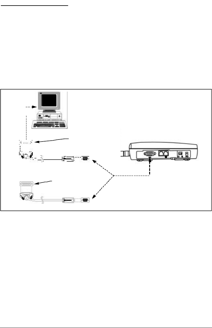
The SX5e features a DB-9 digital computer fax/data port for connection to a personal computer
(PC) - not supplied. When connected to a PC, the SX5e’s PC interface is capable of sending
and receiving digital fax and data transmissions, sending and receiving e-mail communications,
and browsing the Internet. (Data speeds may vary depending upon your cellular network.)
PC Data Connection
A data cable - not included - is required for data transmission. To determine the necessary
cable, count the number of PIN connections in the serial port of your PC (see below). If there
are 9 PIN connections in the PC serial port, a DB-9 (female) to DB-9 (male) cable is required. If
there are 25 PIN connections in the PC serial port, a DB-25 (female) to DB-9 (male) cable is
required - See Figure 9.
NOTE: The SX5e does not support direct computer modem (data) operation through the phone
or fax ports.
For specific digital fax/data setup procedures, see Appendix A - How to Setup Your PC
Serial Ports for Phonecell®SX5 Digital Fax/Data.
Sending Digital Fax
No special mode setting is required when sending a digital fax. The PC fax emulator will change
the terminal mode automatically. The SX5e will reset automatically to voice call mode after
sending the fax file.
Receiving Digital Fax
1) Set up standard 19,200 bps modem.
2) Install a commercial PC fax emulator (Winfax, Netfax, etc.).
3) Set the SX5e to PC fax mode when receiving a fax.
Press: **9 4 to set “Always On” fax mode. Wait for dial tone.
Press: **9 7 to set “One Time” fax mode. Wait for dial tone.
4) After receiving a fax message, the SX5e should be reset.
Data Communication (E-Mail)
1) Set up standard 19,200 bps modem.
2) The SX5e is compatible with a communication emulator (hyperterminal).
3) Press: * * 9 3 to set “Data Service” mode.
Figure 9 - PC data connection.
To PC Serial Port
DB-25 (female) to DB-9 (male) Cable
DB-9 (female) to DB-9 (male) Cable
DB-9 cable and PC serial
port have 9 PIN connections
OR
DB-25 cable and PC
serial port have 25
PIN connections
To DB-9 Data Port on FWT
Phonecell®SX5e GSM 22 Technical Manual

Browsing the Internet
1) Set up standard 19,200 bps modem.
2) Use dial-up networking setting.
3) Press:* * 9 3 to set “Data Service” mode.
Phonecell®SX5e GSM 23 Technical Manual

Phonecell®SX5e GSM 24 Technical Manual
Phonecell®SX5e GSM 25 Technical Manual
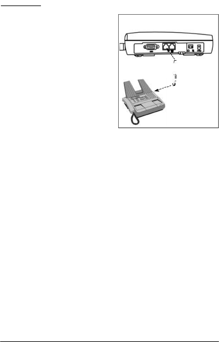
ANALOG FAX
Analog (i.e. normal fax from fax machine) fax calls (CCITT Group 3, Bearer Service TS 62) can
be made from phone and fax jacks, depending
on the option set.
To Send Fax Calls
1) Set up your fax machine just as you would
for a wired telephone.
2) Outgoing fax calls at the fax jack are
processed directly. Outgoing fax calls at the
phone jack always require the analog fax
bypass string, since the default for this jack
is voice calls. See the User Programming
Commands section of this manual for analog
fax setup.
NOTE: Make sure the fax machine is properly
connected as shown in Figure 7.
To Receive Fax Calls
By factory default, you do not have to do any-
thing to receive a fax, provided you have set-up
your fax machine as shown in Figure 7.
However, the user can have options to receive a
fax through the phone port. Refer to the User
Programming section of this addendum for
instructions on programming of the single jack
option and in-bound fax port option.
To Set Up Analog Fax Bypass String
NOTE: The analog fax bypass string can only be used in single jack operation.
This feature allows the phone jack to process the next outgoing call as an analog fax call. After
this call, the phone jack automatically returns to the default voice protocol. The user enters this
string prior to dialing the telephone number. The terminal interprets the string and properly sets
up the call. Refer to the following examples.
To Send a Fax on a Fax Machine Connected to the Phone Jack:
1) Lift up the handset (take off-hook).
2) Dial # * 19 * 1 #, followed by the fax number to be called.
3) Press START on the fax machine.
NOTE: If the fax machine does not have a handset, enter # * 19 * 1 #, followed by the remote
fax number to be called. Press START.
If the fax machine has the capability to store telephone numbers for speed dialing, the # * 19 * 1
# command string may be programmed into the machine as a prefix to the telephone number.
With some machines, it may also be possible to store the command string as a speed dial num-
ber and dial the remote fax machine telephone number manually.
Figure 10 - Analog Fax Connection.

Dual/Single Jack Operation
The Phonecell®SX5 may be operated in either dual-jack or single-jack mode. The factory
default is dual-jack mode.
Dual-Jack Operation
In dual-jack operation, for outgoing calls, the first jack to seize the line (go off-hook) will discon-
nect the other jack. The other jack will remain disconnected until the first jack goes back on-
hook. For incoming calls, voice calls will be routed to the phone voice jack and fax calls will be
routed to the fax jack.
Single-Jack Operation
The analog fax jack can be disabled leaving only the voice phone jack operational (single-jack
operation). In single-jack operation, voice calls can be placed and received normally if a tele-
phone is connected. If a fax is connected, incoming analog fax calls can be received normally,
but to place outbound fax calls using the voice jack, a bypass sequence must be used as a pre-
fix in the dialed telephone number. The analog fax jack will not generate dial tone nor ring signal
if it is disabled.
To Set A Single - Jack Option
The following key sequence is used to enable or disable fax jack operation in favor of single
jack operation (all telephone calls through phone jack):
# *63 *<single jack> #
The single jack value is set to 0for single fax jack operation; 1for both voice and fax
jacks. If the single jack value is neither 0nor 1, it is considered invalid. The factory
default is 1.
To Set In-Bound Fax Port Option
The following key sequence is used to enter the inbound fax port option:
# * 67 * <fax_port> #
The fax port value is set to 1 incoming fax calls to the fax port (dual port operation), or phone
port (single port operation), and 3 to send incoming fax calls to the DB - 9 PC port. If the fax
port value is neither 1 nor 3, it is considered invalid. The factory default is 1.
NOTE: If the single jack option above is set to single, all incoming analog calls will always go to
the phone port.
Phonecell®SX5e GSM 26 Technical Manual

PHONECELL SX5E TROUBLESHOOTING
Telephone Service is Not Working
If the telephone service is not working, first check the operation of the telephone equipment and
wiring connected to your Phonecell®SX5. Test the equipment on a different service or piece of
equipment to ensure proper operation, or connect a known good telephone device to the phone
port on the Phonecell®SX5. This will verify the condition of the telephone equipment and the
internal wiring of the telephone service to ensure that it’s working properly. If the telephone sys-
tem or wiring is not working properly, replace or repair the equipment as required. Otherwise,
contact your cellular provider or your authorized Telular distributor.
Unable to Receive Incoming Calls
If more than one telephone or telephone device is connected to your Phonecell®SX5, make
sure that all devices are “on-hook” (hung up). If one extension is “off-hook” (off its cradle), none
of the extensions on your phone line will ring when an incoming call occurs.
Moisture or Ventilation Problems
Visually inspect your Phonecell®SX5’s unit enclosure. Moisture can damage the equipment.
Ventilation is also very important. If there are moisture or ventilation problems, move your
Phonecell®SX5 to correct as necessary. See the Temperature Environment section of this man-
ual.
No Power
The power LED lamp on the front of your Phonecell®SX5 indicates the unit’s power condition. If
the LED is GREEN, your Phonecell®SX5 is receiving power. If the power cord is connected and
the LED lamp is not lit, the Phonecell®SX5 is not receiving power. Verify that the AC power
source and its corresponding circuit breaker are functioning properly.
Battery Backup Failure
If you’re using the battery, the unit must be connected to AC power for at least 15 hours to fully
charge the battery before it will provide back-up power to your Phonecell®SX5. Verify that the
battery has been charged for at least 15 hours and that the power source and its corresponding
circuit breaker are functioning properly. Then, examine the battery for physical damage and cor-
rosion. Replace the battery if necessary.
Phonecell®SX5e GSM 27 Technical Manual

SAFETY INFORMATION
Your Phonecell®SX5 functions as both a radio transmitter and receiver. When it is ON, the FWT
receives and sends out radio frequency (RF) energy. The GSM 800 unit operates in the fre-
quency range between 824 and 894 MHz, and the GSM 1900 between 1850 MHz and 1990
MHz. Both employ commonly used phase/frequency modulation techniques. When you use your
Phonecell®SX5, the cellular system handling your call controls the power level at which your
unit transmits.
Exposure to RF (Radio Frequency) Energy
In 1991, the Institute of Electrical and Electronics Engineers (IEEE), and in 1992, the American
National Standards Institute (ANSI), updated the 1982 ANSI Standard for safety levels with
respect to human exposure to RF energy. After reviewing the available body of research, more
than 120 scientists, engineers and physicians from universities, government health agencies
and industry developed this updated Standard. In March, 1993, the U.S. Federal
Communications Commission (FCC) proposed the adoption of this updated Standard.
The design of your Telular Phonecell®SX5 complies with this updated Standard. Of course, if
you want to limit RF exposure even further than the updated ANSI Standard, you may choose to
control the duration of your calls and operate your phone in the most power-efficient manner.
Safe Operation Requirement
Do not operate your Phonecell®SX5 when any person is within 8 inches (20 cm) of the antenna.
Temperature Environment
Operating Temperature: From -20°C to +60°C ; Up to 95% relative humidity (non-condensing).
Storage Temperature: From -25°C to +75°C; Up to 95% relative humidity (non-condensing).
Antenna Care and Replacement
Do not use the Phonecell®SX5 with a damaged antenna. If a damaged antenna comes into
contact with the skin, a minor burn may result. Have your antenna replaced by a qualified tech-
nician immediately. Use only a manufacturer-approved antenna. Unauthorized antennas, modifi-
cations, or attachments could damage the Phonecell®SX5.
Driving
Check the laws and regulations on the use of cellular products in the areas where you drive.
Some jurisdictions prohibit your using a cellular device while driving a vehicle. Even if your juris-
diction does not have such a law, we strongly suggest that, for safety reasons, the driver use
extreme caution when operating the cellular device while the vehicle is in motion. Always obey
the law.
Exposure to electronic Devices
Most modern electronic equipment is shielded from RF energy. However, RF energy from cellu-
lar devices may affect inadequately shielded electronic equipment.
RF energy may affect improperly installed or inadequately shielded electronic operating and
entertainment systems in motor vehicles. Check with the manufacturer or its representative to
determine if these systems are adequately shielded from external RF energy. You should also
check with the manufacturer of any equipment that has been added to your vehicle.
Consult the manufacturer of any personal medical devices (such as pacemakers, hearing aids,
etc.) to determine if they are adequately shielded from external RF energy.
Turn your Phonecell®SX5 OFF in health care facilities when any regulations posted in the areas
instruct you to do so. Hospitals or health care facilities may be using equipment that could be
sensitive to external RF energy.
Phonecell®SX5e GSM 28 Technical Manual
WARNING!
Only Authorized Service Personnel should remove the cover of your
Phonecell®SX5.For further assistance, contact your Authorized Telular
Representative. Please have your unit’s model and serial number ready.
!

Phonecell®SX5e GSM 29 Technical Manual
Aircraft
Turn OFF your Phonecell®SX5 before boarding any aircraft.
• Use it on the ground only with crew permission.
• Do not use it in the air.
To prevent possible interference with aircraft systems, U.S. Federal Aviation Administration
(FAA) regulations require you to have permission from a crew member to use your cellular
phone (or any other cellular product) while the plane is on the ground. To prevent interference
with aircraft systems, FCC regulations prohibit using your cellular device while the plane is in
the air.
Children
Do not allow children to play with your Phonecell®SX5 to prevent damage to the unit.
Blasting Areas
Construction crews often use remote control RF devices to set off explosives. Therefore, to
avoid interfering with blasting operations, turn your Phonecell®SX5 OFF when in a "blasting
area" or in areas posted: "Turn off two-way radio."
Potentially Explosive Atmospheres
Turn your Phonecell®SX5 OFF when in any area with a potentially explosive atmosphere. It is
rare, but your Phonecell®SX5 or its accessories could generate sparks. Sparks in such areas
could cause an explosion or fire resulting in bodily injury or even death.
Areas with a potentially explosive atmosphere are often, but not always, clearly marked. They
include fueling areas such as gas stations; below deck on boats; fuel or chemical transfer or
storage facilities; areas where the air contains chemicals or particles, such as grain, dust, or
metal powders; and any other area where you would normally be advised to turn off your vehicle
engine.
Do not transport or store flammable gas, liquid or explosives in the area of your Phonecell®SX5
or accessories.
Vehicles using liquefied petroleum gas (such as propane or butane) must comply with the
National Fire Protection Standard (FPA-58). For a copy of this standard, contact the National
Fire Protection Association, One Batterymarch Park, Quincy, MA 02269, Attn: Publications
Sales Division.
FCC Part 15 Class B Compliance
This Phonecell®SX5 model has been tested and found to comply with the limits for a Class B
digital device, pursuant to Part 15 of the FCC rules. These limits are designed to provide rea-
sonable protection against harmful interference in a residential installation. This equipment gen-
erates, uses and can radiate radio frequency energy and, if not installed and used in accor-
dance with the instructions, may cause harmful interference to radio communications. However,
there is no guarantee that interference will not occur in a particular installation. If this equipment
does cause harmful interference to radio or television reception, which can be determined by
turning the equipment OFF and ON, the user is encouraged to try to correct the interference by
one or more of the following measures:
• Reorient or relocate the antenna.
• Increase the separation between the equipment and the terminal.
• Connect the equipment into an outlet on a circuit different from that to which the terminal is
connected.
• Consult your Authorized Telular Distributor or an experienced radio/TV technician for help.
WARNING!
Your Phonecell®SX5 is intended either to be wall mounted or mounted on a
flat surface to allow proper ventilation. Do not block the space beneath your
Phonecell®SX5 as this could cause the unit to overheat and fail.
!

IMPORTANT NOTICES
Warranty
I. WHAT THIS WARRANTY COVERS AND FOR HOW LONG:
TELULAR CORPORATION ('Telular") warrants to a distributor Buyer, or to a customer only if the
customer is a Buyer directly from Telular, that the Products (including accessories) shall comply
with the applicable Specifications and shall be free from defects in material and workmanship
under normal use and service for a period of fifteen (15) months from date of shipment from
Telular. Telular, at its option, shall at no charge either repair, replace or refund the purchase
price of the Product during the warranty period, provided it is returned by Buyer in accordance
with the terms of this warranty to the Telular designated repair center. Repair or replacement, at
Telular's option, may include the replacement of parts, boards or Products with functionally
equivalent reconditioned items. Repaired and replacement items are warranted for the balance
of the original warranty period. All replaced items shall become the property of Telular. SUCH
ACTION ON THE PART OF TELULAR SHALL BE THE FULL EXTENT OF TELULAR'S LIA-
BILITY HEREUNDER, AND BUYERS EXCLUSIVE REMEDY. Buyer shall be responsible for all
costs and expenses incurred by Buyer including without limitation any handling, labor or trans-
portation charges. OTHER THAN AFORESAID, THIS EXPRESS WARRANTY IS EXTENDED
BY TELULAR TO BUYER ONLY AND NOT TO BUYER'S CUSTOMERS OR USERS OF
BUYER'S PRODUCTS.
II. HOW TO OBTAIN WARRANTY SERVICE
Product covered under this warranty shall only be accepted from and returned to Buyer's desig-
nated repair center. Buyer's dealers, distributors, agents, and end users cannot submit items to
Telular under this warranty. To receive warranty service an RMA number must first be obtained
from Telular Technical Support. The defective or non-compliant Product should be sent by Buyer
freight pre-paid to: Telular Corporation, 647 North Lakeview Parkway, Vernon Hills, IL 60061,
USA or other designated location. The product must be packaged in the original carton and
packing material or an equivalent package and must have the assigned RMA number clearly
marked on the carton. Returned Product received without an RMA number will be returned to
the sender.
III. WARRANTY CONDITIONS:
This is the complete warranty for the Products manufactured by Telular and sold to Buyer.
Telular assumes no obligation or liability for additions or modifications to this warranty unless
made in writing and signed by an officer of Telular. Unless made in separate written agreement
between Telular and Buyer, Telular does not warrant the installation, field maintenance or serv-
ice of the Products or parts.
TELULAR CANNOT BE RESPONSIBLE IN ANY WAY FOR ANY ANCILLARY EQUIPMENT
NOT FURNISHED BY TELULAR WHICH IS ATTACHED TO OR USED IN CONNECTION
WITH THE PRODUCTS OR FOR OPERATION OF THE PRODUCTS WITH ANY ANCILLARY
EQUIPMENT AND ALL SUCH EQUIPMENT IS EXPRESSLY EXCLUDED FROM THIS WAR-
RANTY. FURTHERMORE, TELULAR CANNOT BE RESPONSIBLE FOR ANY DAMAGE TO
THE PRODUCTS RESULTING FROM THE USE OF ANCILLARY EQUIPMENT NOT FUR-
NISHED BY TELULAR FOR USE WITH THE PRODUCTS.
WHEN THE PRODUCT IS USED IN CONJUNCTION WITH ANCILLARY OR PERIPHERAL
EQUIPMENT NOT MANUFACTURED BY TELULAR, TELULAR DOES NOT WARRANT THE
OPERATION OF THE PRODUCT/PERIPHERAL COMBINATION, AND TELULAR SHALL
HONOR NO WARRANTY CLAIM WHERE THE PRODUCT IS USED IN SUCH A COMBINA-
TION AND IT IS DETERMINED BY TELULAR THAT THERE IS NO FAULT WITH THE PROD-
UCT. TELULAR DISCLAIMS LIABILITY FOR RANGE, COVERAGE, AVAILABILITY, OR
OPERATION OF THE CELLULAR SYSTEM WHICH IS PROVIDED BY THE CARRIER.
Phonecell®SX5e GSM 30 Technical Manual

IV. WHAT THIS WARRANTY DOES NOT COVER:
(a) Subsequent upgrades and enhancements to the Product. (b) Defects, non-compliance or
damage resulting from use of the Product in other than its normal and customary manner or
environment. (c) Defects, noncompliance or damage from misuse, lightening, accident or neg-
lect. (d) Defects, noncompliance or damage from improper testing, operation, maintenance,
installation, adjustment, or any alteration or modification of any kind. (e) Product disassembled
or repaired in such a manner as to adversely affect performance or prevent adequate inspection
and testing to verify any warranty claim. (f) Product which has had the serial number removed
or made illegible. (g) Defects, non-compliance or damage due to spills of food or liquid. (h) All
plastic surfaces and all other externally exposed parts that are scratched or damaged due to
customer normal use. (i) Costs and expenses, including without limitation handling, labor and
transportation, incurred in returning Product for warranty service to Telular's Repair Center. (j)
Repair, programming or servicing by someone other than Telular.
V. GENERAL PROVISIONS:
THIS WARRANTY IS GIVEN IN LIEU OF ALL OTHER EXPRESS OR STATUTORY WAR-
RANTIES. IMPLIED WARRANTIES, INCLUDING WITHOUT LIMITATION IMPLIED WAR-
RANTIES OF MERCHANTABILITY, FITNESS FOR A PARTICULAR PURPOSE, TITLE,
INFRINGEMENT, DELIVERY, NEGLIGENCE AND PERSONAL INJURY, ARE DISCLAIMED.
FURTHER, AS THE CELLULAR CARRIER IS NOT CONTROLLED BY TELULAR, NO WAR-
RANTY IS MADE AS TO COVERAGE, AVAILABILITY OR GRADE OF SERVICE PROVIDED
BY THE CELLULAR CARRIER. IN NO EVENT SHALL TELULAR BE LIABLE FOR DAM-
AGES IN EXCESS OF THE PURCHASE PRICE OF THE PRODUCT, FOR ANY LOSS OF
USE, LOSS OF TIME, INCONVENIENCE, COMMERCIAL LOSS, LOST PROFITS OR SAV-
INGS OR OTHER INCIDENTAL, SPECIAL OR CONSEQUENTIAL DAMAGES ARISING OUT
OF THE USE OR INABILITY TO USE SUCH PRODUCT TO THE FULL EXTENT SUCH MAY
BE DISCLAIMED BY LAW. SOME JURISDICTIONS DO NOT ALLOW THE EXCLUSION OR
LIMITATIONS OF INCIDENTAL OR CONSEQUENTIAL DAMAGES OR LIMITATION ON HOW
LONG AN IMPLIED WARRANTY LASTS.
VI. SOFTWARE PROVISIONS:
Laws in the United States and other countries preserve for Telular certain exclusive rights for
copyrighted Telular software such as the exclusive rights to reproduce in copies and distribute
copies of such Telular software. Telular software may be copied into, used in and redistributed
with only the Product associated with such Telular software. No other use, including without limi -
tation, disassembly of such Telular software or exercise of exclusive rights in such Telular soft-
ware is permitted and Telular reserves all rights not expressly granted in this Limited
Commercial Warranty.
Patents:
Telular Corporation products are protected and manufactured under one or more of the following
U.S. patents and related international patents and patents pending relating thereto: 4,658,096;
4,737,975; 4,775,997; 4,868,519; 4,922,517; 5,134,651; 5,361,297; 5,469,494; 5,046,085;
5,715,296.
Trademarks:
Telular Corporation owns the following registered trademarks: TELULAR and design, TELULAR,
CELJACK, MAXJACK, TELCEL, HEXAGON LOGO, PHONECELL, CELSERV, TELGUARD,
CPX, and AXCELL.
Phonecell®SX5e GSM 31 Technical Manual
APPENDIX A:
HOW TO SETUP PC SERIAL PORTS FOR PHONECELL DIGITAL FAX/DATA
Requirements
· GSM account with your network service provider including a Data/Fax facility.
· PC/Laptop/ Notebook with Com Port.
· Windows 95/98
NOTE: When all of the above have been satisfied, you may proceed.
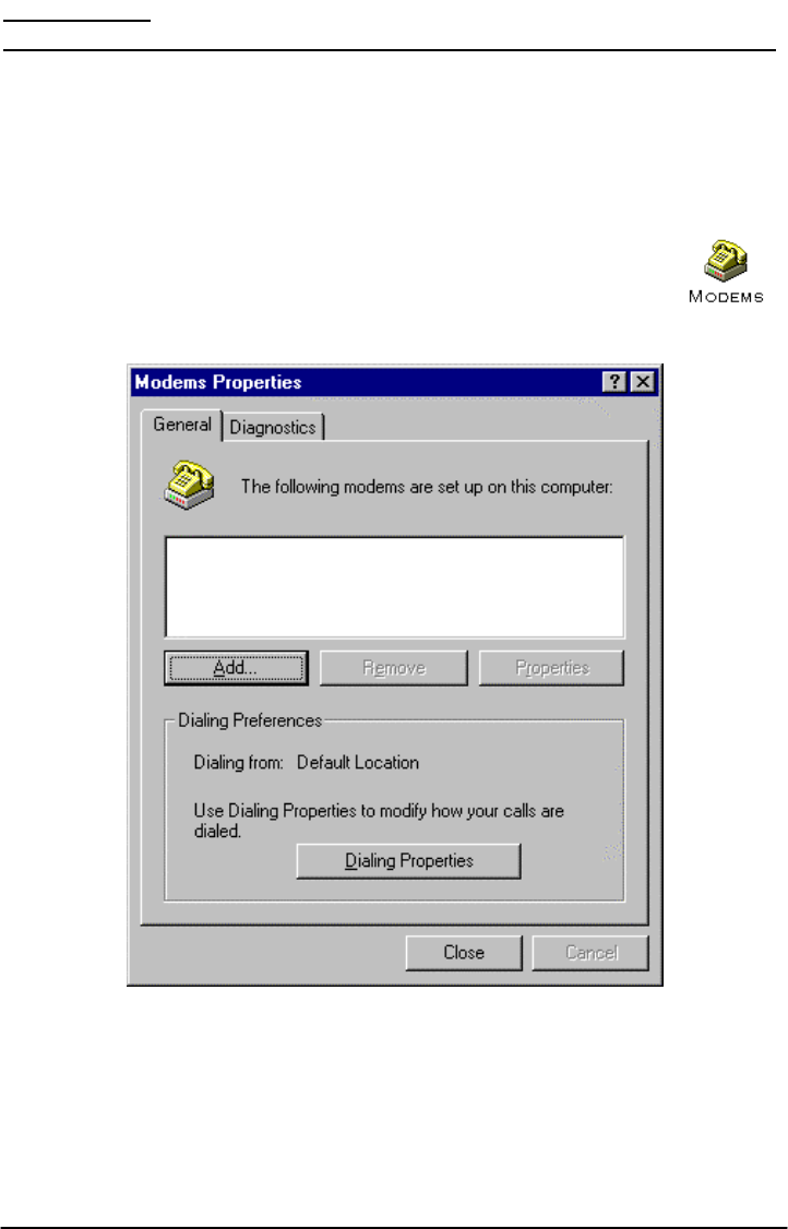
Modem Setup
1) Power on your PC/laptop and start Windows 95/98.
2) Using the PC pointing device, press the "START" button, select "SETTINGS"
and then "CONTROL PANEL". Once the Control Panel window appears dou-
ble click the MODEMS icon button. The modem properties window will
appear.
NOTE: A data card modem device may appear in the list of installed modems.
3) Click the ADD button to install a new modem device for the Phonecell®SX5.
Phonecell®SX5e GSM 32 Technical Manual
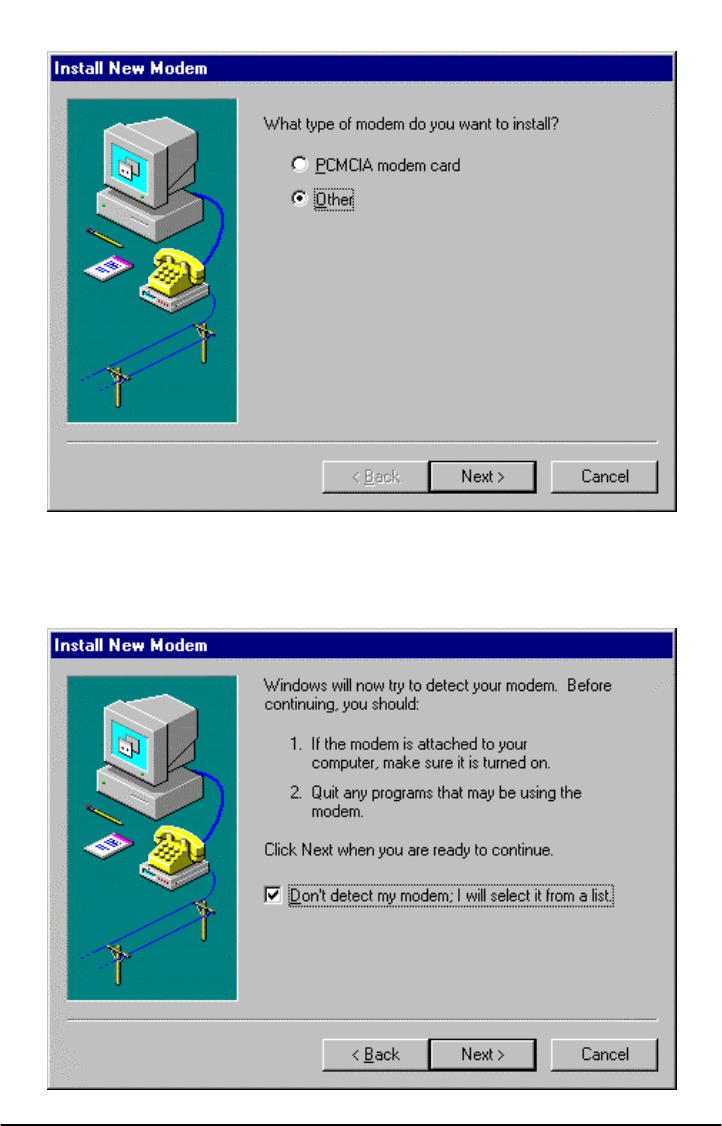
4)
The install new modem window may appear asking for the type of modem to install. Click on
"Other" followed by clicking the NEXT button. If this window does not appear, go to Step 5.
5) The install new modem window will appear. Then, click on the "Don't detect my modem
option" followed by clicking the NEXT button.
Phonecell®SX5e GSM 33 Technical Manual
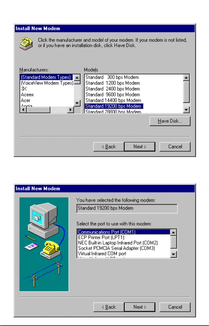
6)
The install new modem will update again to select the manufacturer and modem model.
Click on "Standard Modem Types" from the manufactures list followed by "Standard 19200
bps Modem" from the model list. Then click on the NEXT button.
7) The install new modem will update to select the com port. Click on the available serial port
and then click on the "Next" button. Windows 95 will create a modem configuration file for
the Phonecell®SX5. This may take several minutes.
Phonecell®SX5e GSM 34 Technical Manual
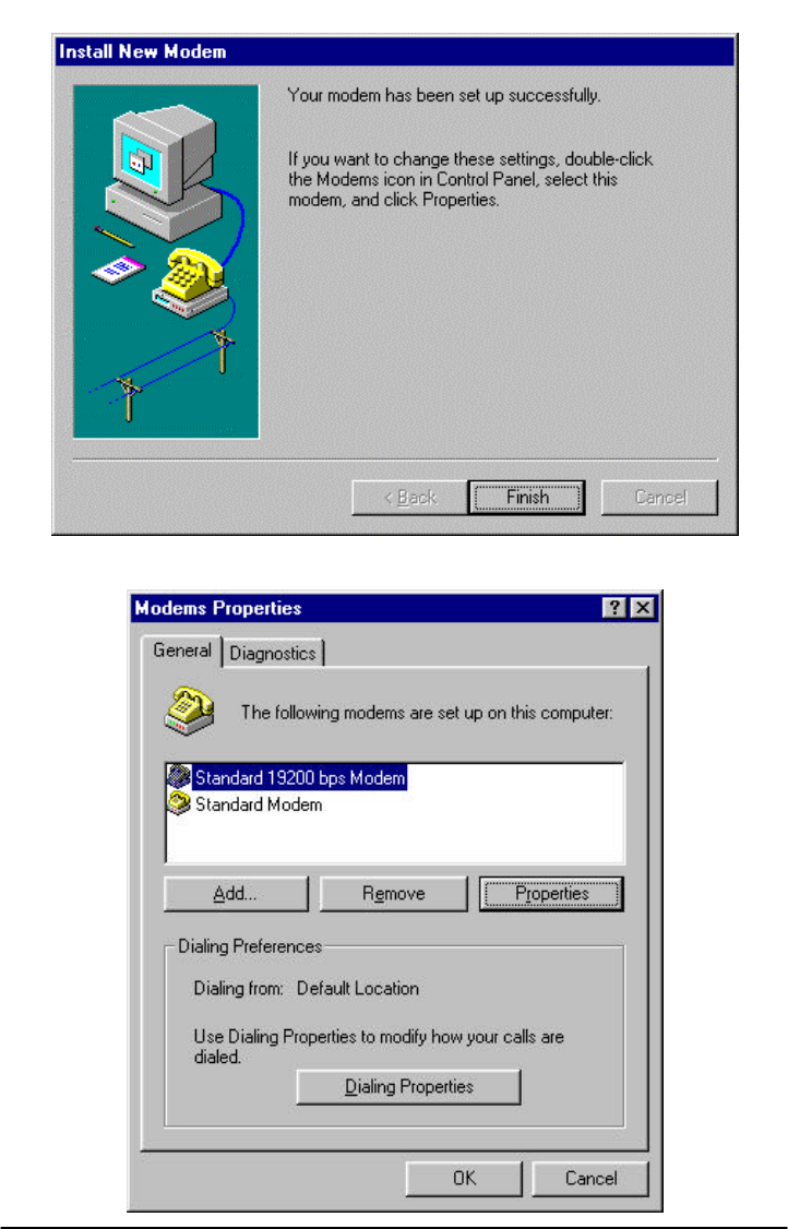
8) The Install New Modem window will update again. Click on Finish to proceed.
9) The Modems Properties window should appear. Click on the Properties button.
Phonecell®SX5e GSM 35 Technical Manual
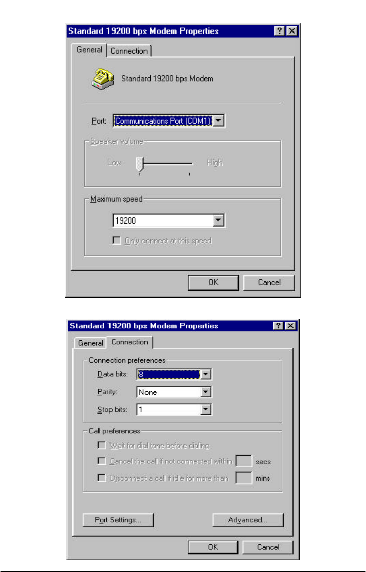
10)
The Standard 19200 bps Modem Properties window will open in the General tab. Set as
shown with the com port you have selected.
11) Then click on the Connection tab. Set as shown below.
Phonecell®SX5e GSM 36 Technical Manual
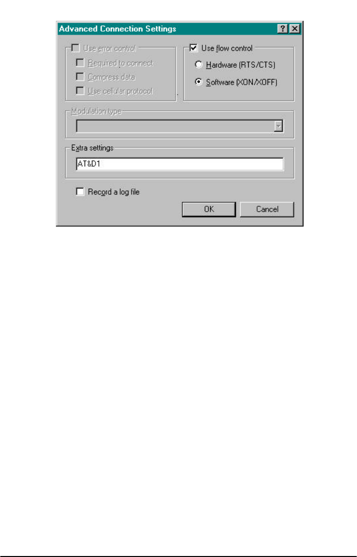
12) Click on the Advanced button. Set as shown.
13) Click on OK and Close to back out of each window. Your modem is now set up.
Phonecell®SX5e GSM 37 Technical Manual