Testo SE and KGaA AMB2520T 2.4 GHz Transceiver module User Manual manual 2
Testo AG 2.4 GHz Transceiver module manual 2
UserManual.wiki
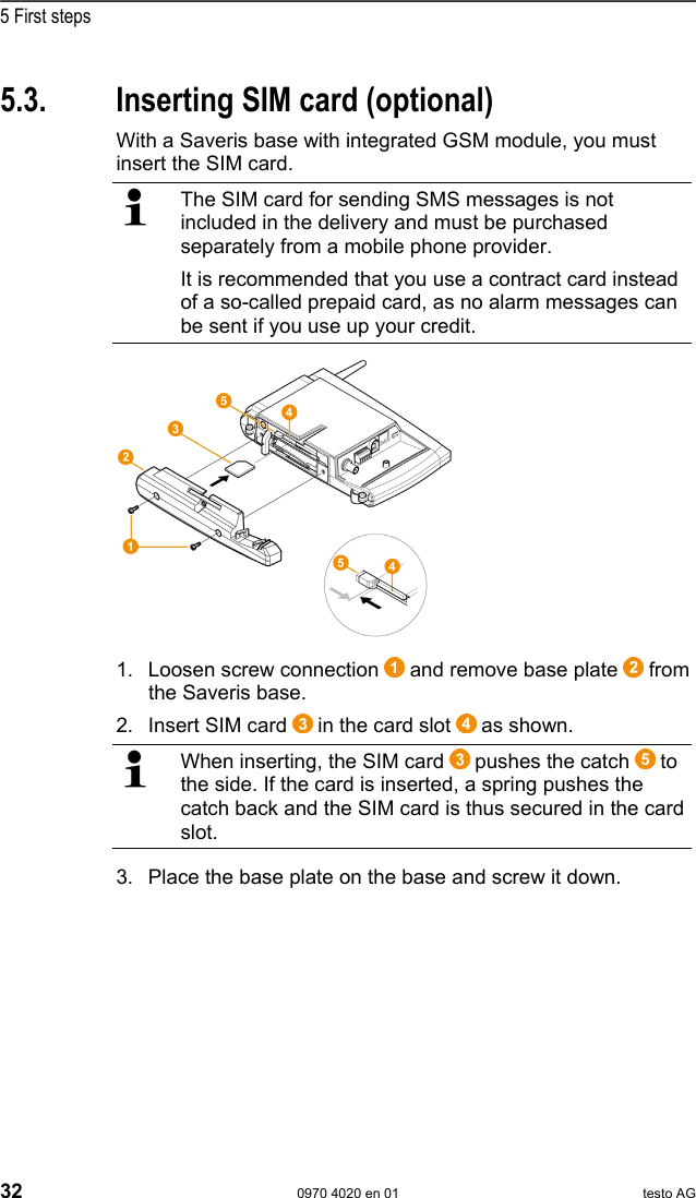
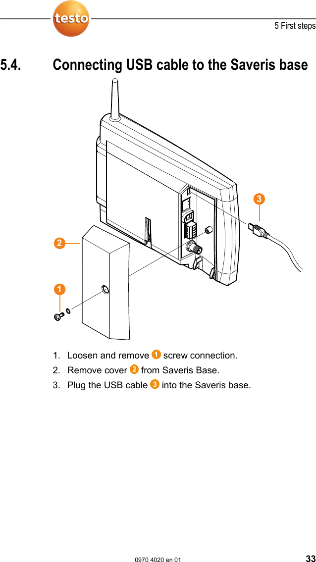
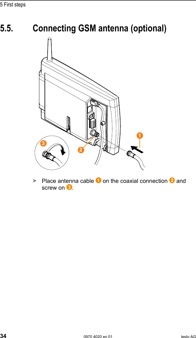
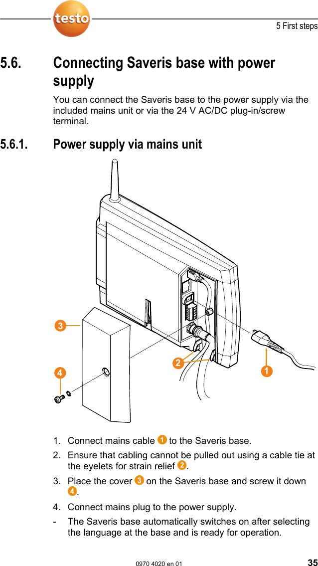
>
Testo SE and KGaA
>
AMB2520T User Manual
>
manual 2
Contents
1.
manual 1
2.
manual 2
manual 2
Navigation menu
Upload a User Manual
Namespaces
Wiki Guide
HTML
PDF
Info
Views
User Manual
Discussion / Help
Navigation

![2 Safety and the environment 0970 4020 en 01 7 Pos: 3 /TD/Überschr iften/2. Sicher heit und Umwelt @ 0\mod_11737747 19351_79.doc @ 292 2 Safety and the environment Pos: 4 /TD/Überschr iften/2.1 Zu diesem Doku ment @ 0\mod_117377525235 1_79.doc @ 346 2.1. About this document Pos: 5 /TD/Sicherhei t und Umwelt/Zu diesem Doku ment/Symbole und Schr eibkonv. [Saveris] @ 0\ mod_1193735939953_79. doc @ 5623 Symbols and writing standards Representation Explanation Warning advice, risk level according to the signal word: Warning! Serious physical injury may occur. Caution! Slight physical injury or damage to the equipment may occur. > Implement the specified precautionary measures. Note: Basic or further information. 1. ... 2. ... Action: more steps, the sequence must be followed. > ... Action: a step or an optional step. - ... Result of an action. ... ... Position numbers for the clarification of the relationship between text and picture. Menu Elements of the instrument, the instrument display or the program interface. [OK] Control keys of the instrument or buttons of the program interface. ... | ... Functions/paths within a menu. “...” Example entries Pos: 6 /TD/Sicherhei t und Umwelt/Zu diesem Doku ment/Verwendung (Sa veris) @ 0\mod_11913287705 62_79.doc @ 5412](https://usermanual.wiki/Testo-SE-and-KGaA/AMB2520T.manual-2/User-Guide-939158-Page-8.png)
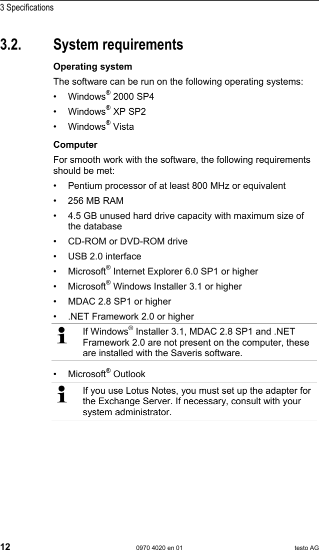
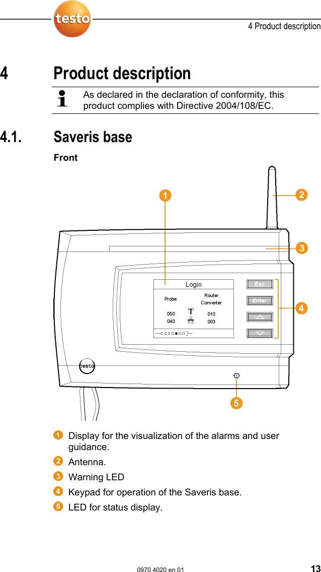
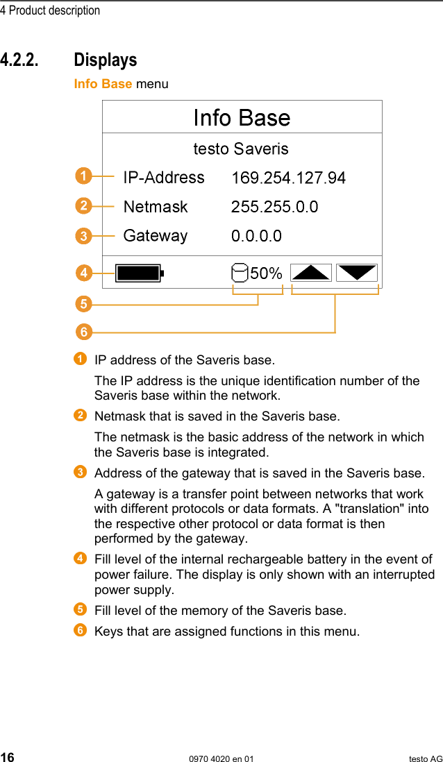
![4 Product description 0970 4020 en 01 15 Pos: 29 /TD/Produktb eschreibung/Übersic ht/testo Saveri s/00 Base/02 Base GSM @ 1\mod_1 196957066669_79.doc @ 6084 4.2. Saveris base GSM module (optional) Insertion slot for the SIM card. Pos: 30 /TD/Produktb eschreibung/Übersic ht/testo Saveri s/00 Base/Bedientast en @ 0\mod_1190205422265_ 79.doc @ 4893 4.2.1. Control keys Key Explanation [Esc] Switches from the Login menu to the Info System menu. [Enter] In the Info System menu starts up the login status for the probe. [ ▲ ], [ ▼ ] Navigation buttons for changing the menus. Pos: 31 /TD/Produktb eschreibung/Übersic ht/testo Saveri s/00 Base/Displayanzei gen @ 0\mod_1190205462 296_79.doc @ 4902 *](https://usermanual.wiki/Testo-SE-and-KGaA/AMB2520T.manual-2/User-Guide-939158-Page-16.png)
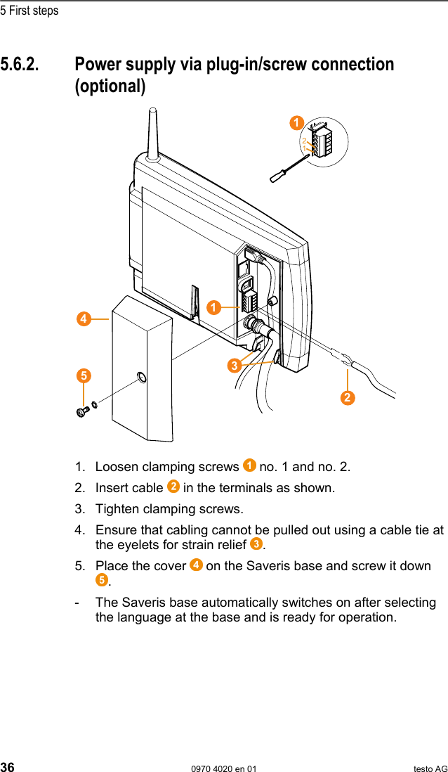
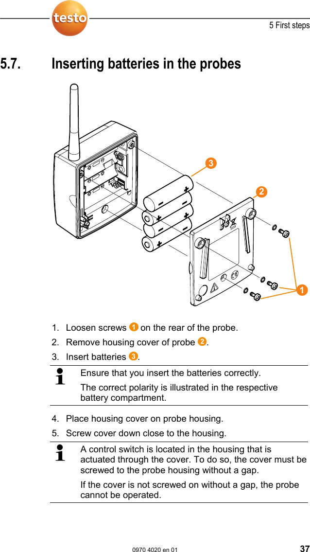
![5 First steps 38 0970 4020 en 01 testo AG Pos: 64 /TD/Erste Sc hritte/testo Saveris/ 03 Fühler an der Base anmeld en @ 0\mod_1188478029328 _79.doc @ 2964 Integrating Saveri s router (optional) Page 52 5.8. Connecting radio probe You can connect a maximum of 15 probes to the Saveris base directly via radio. In addition, you can operate 15 more probes at the Saveris Base per converter and 5 per router. Note that a maximum of 254 channels can be processed by the Saveris software. 1. Change to the Info System menu at the Saveris base with the [▼] button. 2. Press [Enter] to call up the Login function. - The status bar in the display shows that the Saveris base is ready for probe detection.](https://usermanual.wiki/Testo-SE-and-KGaA/AMB2520T.manual-2/User-Guide-939158-Page-39.png)
![5 First steps 0970 4020 en 01 39 3. Hold down the connect key on the rear of the probe until the LED at the probe begins to flash orange. - The LED at the probe briefly turns green if this was detected by the Saveris base. The LED at the Saveris base briefly flashes green and a prompt appears in the display of the base for the connection of more probes or routers. Multiple probes cannot be connected at the Saveris base simultaneously. Multiple probes can only be connected one after the other. 4. At the Saveris base, press the • [Esc] key if no more components are to be connected. - A note on the required performance of the startup assistant is shown on the display for about ten seconds. Then the Saveris base changes to the Info System menu in which the number of connected components is now shown. • Press [Enter] if further components are to be connected; see previous step.](https://usermanual.wiki/Testo-SE-and-KGaA/AMB2520T.manual-2/User-Guide-939158-Page-40.png)
![5 First steps 0970 4020 en 01 41 Pos: 66 /TD/Erste Sc hritte/testo Saveris/ 04 Hardware inbetriebn ehmen @ 0\mod_11884781 13640_79.doc @ 2982 5.10. Starting up hardware The following preconditions must be fulfilled for the startup of the hardware: • the Saveris base is ready for operation, • all probes are connected to the Saveris base and • the Saveris software is installed on the computer. 1. Connect the Saveris base to the computer via the USB cable. - The startup assistant starts. Under Windows 2000, you must manually call up the assistant using Start | All Programs | Testo | Startup Assistant. 2. Click on [Continue >]. - The general system settings of the Saveris base are shown.](https://usermanual.wiki/Testo-SE-and-KGaA/AMB2520T.manual-2/User-Guide-939158-Page-42.png)
![5 First steps 42 0970 4020 en 01 testo AG 3. Click on [Synchronize] to apply the date and time from the operating system of the computer to the Saveris base. 4. Click on [Continue >]. - If the Saveris base is equipped with a GSM module the dialogue for entering the basic settings for the SMS service is shown. If there is no GSM module continue with step 7.](https://usermanual.wiki/Testo-SE-and-KGaA/AMB2520T.manual-2/User-Guide-939158-Page-43.png)
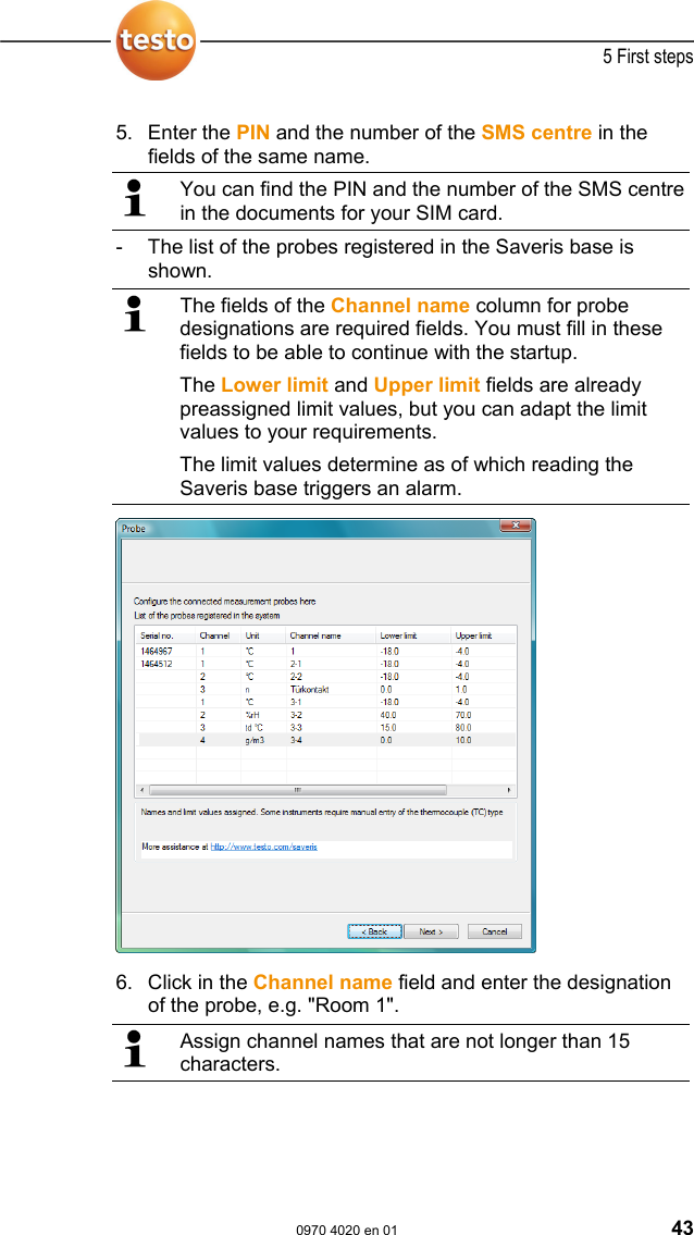
![5 First steps 44 0970 4020 en 01 testo AG > Click in the Lower limit field and change the lower limit value. If all probes are to have the same limit value, click on the column title with the right mouse button and then click on Apply to all in the context menu. This also applies for the upper limit value in the next step. > Click in the Upper limit field and change the upper limit value. > Click in the TC type field and enter the type of thermocouple (Enter: J, K, S or T) if this information is required for the instrument. > Perform step 5 and the following for all other probes until all required fields are filled. 7. Click on [Continue >]. - The settings for measuring cycle, the alarm delay and the alarm issue are shown.](https://usermanual.wiki/Testo-SE-and-KGaA/AMB2520T.manual-2/User-Guide-939158-Page-45.png)
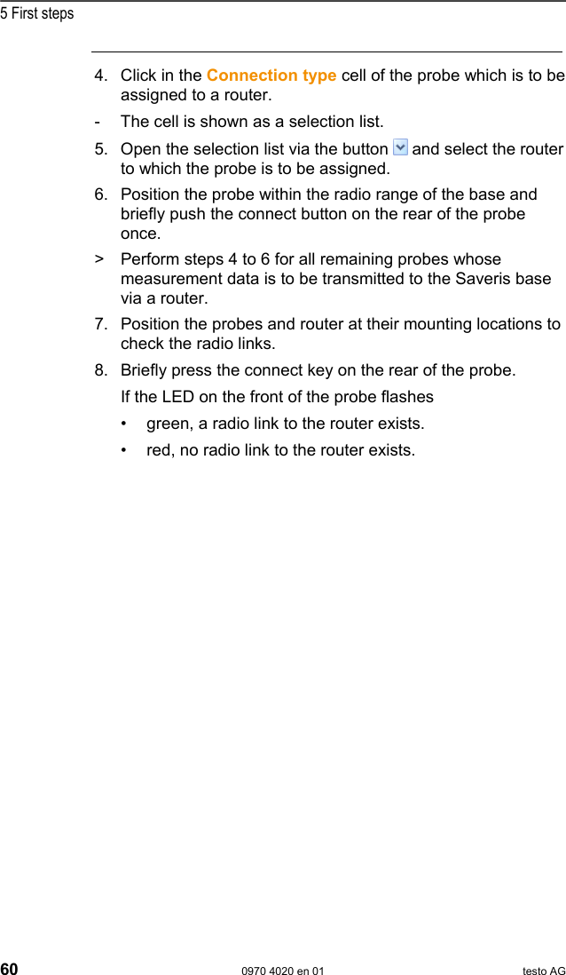
![5 First steps 46 0970 4020 en 01 testo AG 11. Click on [Continue >]. - If a router is connected at the Saveris base the configuration of the connection type for the probes is shown. If no router is connected continue with step 15. 12. Click in the Connection type cell of the probe which is to be assigned to a router. - The cell is shown as a selection list. 13. Open the selection list via the button and select the router to which the probe is to be assigned. 14. Perform steps 12 and 13 for all remaining probes whose measurement data is to be transmitted to the Saveris base via a router. 15. Click on [Continue >]. - If the Saveris base is equipped with a GSM module, the settings for the SMS alarms are shown. If there is no GSM module continue with step 28.](https://usermanual.wiki/Testo-SE-and-KGaA/AMB2520T.manual-2/User-Guide-939158-Page-47.png)
![5 First steps 48 0970 4020 en 01 testo AG 21. Click on [Continue >]. - The settings for the reporting are shown. These specifications are applied as the default setting for the reporting. You can change these settings or create new configurations for the reports at any time; see chapter "Report settings". 22. Deactivate Automatically create reports checkbox if this function should not be used. - In this case, continue with step 20. 23. Determine the intervals in which the reports should be automatically created. 24. Determine which content the reports should include. > Activate Send to receiver checkbox if reports should be sent by e-mail. - The input fields for the e-mail address and the subject line as well as the [Address book] button are shown. > Enter the e-mail address of the recipient in the input field or select the recipient from the Outlook contacts using the [Address book]. > Enter text for the subject line of the e-mail. 25. Enter the address under Cover sheet address field that should be displayed on the top of the report.](https://usermanual.wiki/Testo-SE-and-KGaA/AMB2520T.manual-2/User-Guide-939158-Page-49.png)
![5 First steps 0970 4020 en 01 49 26. Click on [Continue >]. - The wizard is shown with the information on the start of measurement and the list of the registered probes. 27. Postpone the start of measurement, if necessary. > Change the project name in the Name field. Consider a clear-cut name for the project that you will be able to easily associate later. The project name cannot subsequently be changed. 28. Click on [Finish] to complete the startup of the hardware. - A dialogue for displaying and printing the configuration settings is shown.](https://usermanual.wiki/Testo-SE-and-KGaA/AMB2520T.manual-2/User-Guide-939158-Page-50.png)
![5 First steps 50 0970 4020 en 01 testo AG 29. Click on • [Yes] if the settings should be shown in the Internet browser and printed from there. • [No] if the settings should not be shown. The dialogue for the conclusion of the startup is shown. 30. Consecutively press the connect button on all probes to synchronize the probes. 31. Close the dialogue with [OK]. - The hardware is now ready for operation. Pos: 67 /TD/Produkt verwenden/testo Saver is/01 Start/01_Saver is-Software star ten @ 0\mod_1189076832593 _79.doc @ 3933](https://usermanual.wiki/Testo-SE-and-KGaA/AMB2520T.manual-2/User-Guide-939158-Page-51.png)
![5 First steps 0970 4020 en 01 51 5.11. Starting Saveris software Ensure that the Saveris software is not already open, for example in multi-user operation under Windows® Vista. 1. Select [Start] | All Programs | Testo | Saveris. - The Testo Saveris software program window is opened with the Select project dialogue. If the software will not start, check whether the testo tdassvcs service is started in the service management of the operating system and restart it, if needed. 2. Select the • Only active projects option if the data from a running project should be opened • All projects option if the data from a completed project should be opened. 3. Select the project that is to be opened in the tree structure. 4. Confirm with [OK]. - The Testo Saveris software program window is shown with the selected data record in the foreground. Pos: 68 /TD/Erste Sc hritte/testo Saveris/ Hardware erweitern/ Messsystem erweiter n @ 1\mod_1197551581796 _79.doc @ 6327](https://usermanual.wiki/Testo-SE-and-KGaA/AMB2520T.manual-2/User-Guide-939158-Page-52.png)
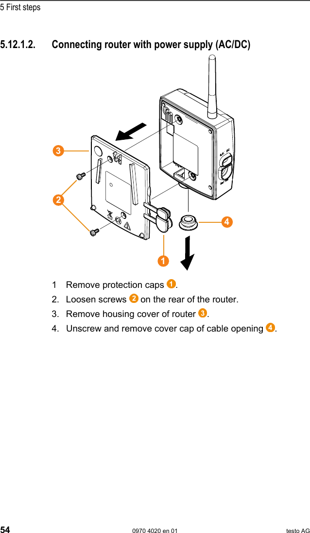
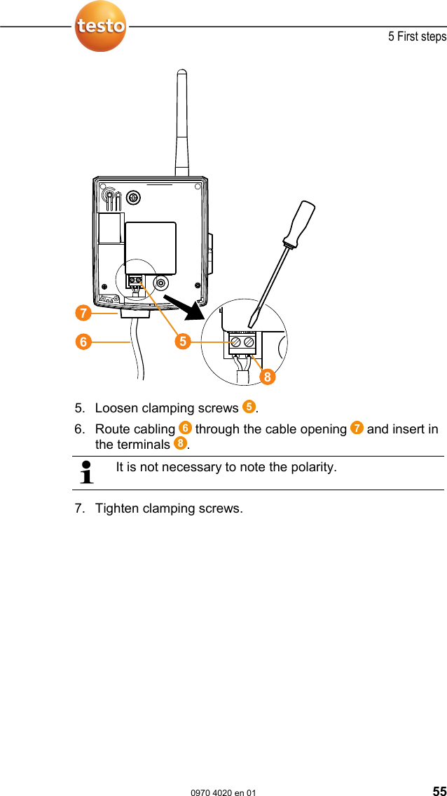
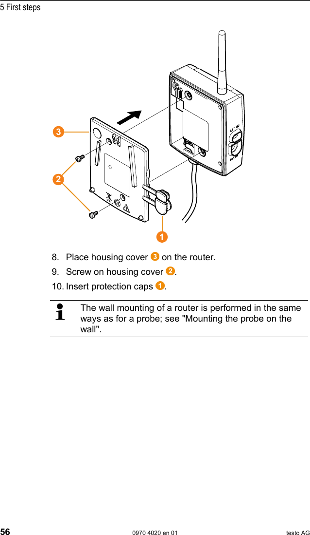
![5 First steps 0970 4020 en 01 57 5.12.1.3. Connecting router You can connect a maximum of 15 routers to the Saveris base. Also note that connecting multiple routers in series is not possible. 1. Change to the Info System menu at the Saveris base with the [▼] button. 2. Press [Enter] to call up the Login function. - The status bar in the display shows that the Saveris base is ready for router detection.](https://usermanual.wiki/Testo-SE-and-KGaA/AMB2520T.manual-2/User-Guide-939158-Page-58.png)
![5 First steps 58 0970 4020 en 01 testo AG 3. Hold down the connect key on the rear of the router until the LED at the router begins to flash orange. - The LED at the router briefly turns green if this was detected by the Saveris base. The LED at the Saveris base briefly flashes green and a prompt appears in the display of the base for the connection of more probes or routers. Multiple routers cannot be connected at the Saveris base simultaneously. Multiple routers can only be connected one after the other. 4. At the Saveris base, press the • [Esc] key if no more components are to be connected. - A note on the required performance of the startup assistant is shown on the display for about ten seconds. Then the Saveris base changes to the Info System menu in which the number of connected components is now shown. • Press [Enter] if further components are to be connected; see previous step. Pos: 73 /TD/Erste Sc hritte/testo Saveris/ Hardware erweitern/ 01 Router einbinden/0 3 Fühler zuweisen @ 1\mod_1197 548250906_79.doc @ 6284 5.12.1.4. Assigning probes To assign a probe to a router, both must be connected in the Saveris base.](https://usermanual.wiki/Testo-SE-and-KGaA/AMB2520T.manual-2/User-Guide-939158-Page-59.png)
![5 First steps 0970 4020 en 01 59 1. Under Start | All Programs | Testo click on Saveris Startup Assistant. - The welcome dialogue of the startup assistant is shown. 2. Click on [Continue >]. - The System status dialogue with the General tab is shown. 3. Change to Router tab. The Direct connection type means that the probe is connected directly in the Saveris base or a converter.](https://usermanual.wiki/Testo-SE-and-KGaA/AMB2520T.manual-2/User-Guide-939158-Page-60.png)
![5 First steps 0970 4020 en 01 67 2. Click on [Continue >]. - The dialogue • Address of the Saveris base is shown if the computer has DHCP. In this case, continue with step 4. • Instrument address allocation is shown if an automatic allocation of the IP address via DHCP is not possible. You must manually enter the connection data. 3. Enter IP address, Netmask and Gateway. The first two blocks of the IP address must match those from the Saveris base. The last two blocks can be selected freely. However, the IP address may not yet be assigned. The IP address, the netmask and the gateway can be read off at the Saveris base in the Info Base menu; also see chapter Displays, page 16. 4. Click on [Continue >]. - The dialogue for the entry of the connection data for the base is shown.](https://usermanual.wiki/Testo-SE-and-KGaA/AMB2520T.manual-2/User-Guide-939158-Page-68.png)
![5 First steps 68 0970 4020 en 01 testo AG 5. Enter IP address of the Saveris base. The IP address can be read off at the Saveris base in the Info Base menu; also see chapter Displays, page 16. 6. Click on [Finish]. - The Ethernet probe is restarted, synchronized with the Saveris base and the number of connected Ethernet probes in the display of the base is increased by 1; see](https://usermanual.wiki/Testo-SE-and-KGaA/AMB2520T.manual-2/User-Guide-939158-Page-69.png)
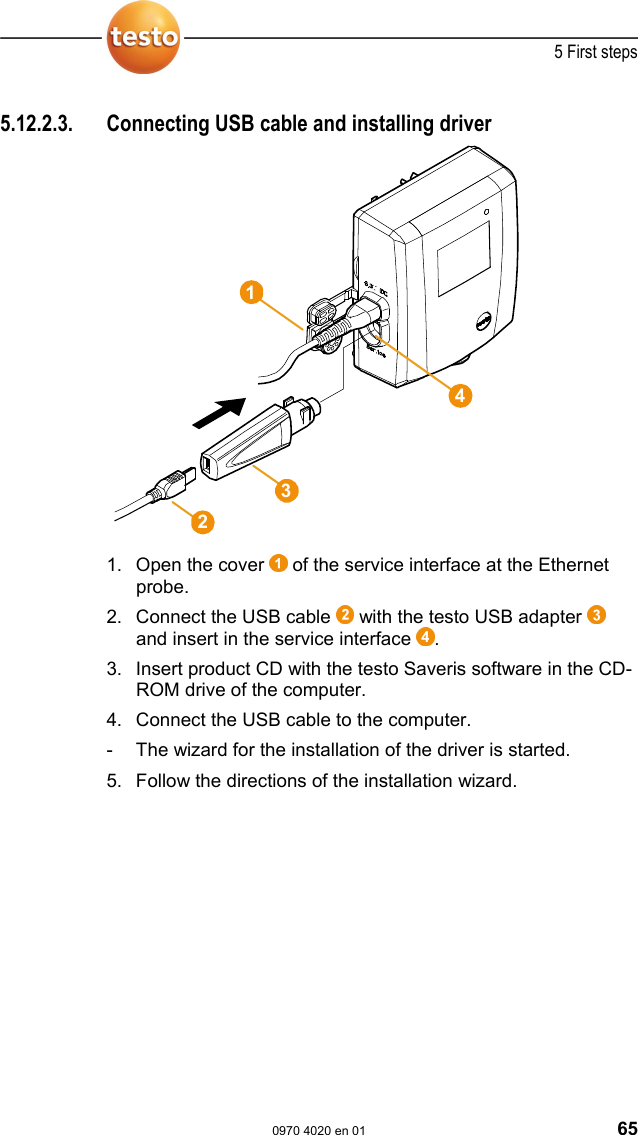
![5 First steps 0970 4020 en 01 71 5.12.2.7. Starting up Ethernet probes 1. Open the assistant for starting up new hardware component via Start | All Programs | Testo | Startup Assistant. - The assistant is opened with the welcome screen. 2. Click on [Continue >]. - The Commission new probe dialogue is shown.](https://usermanual.wiki/Testo-SE-and-KGaA/AMB2520T.manual-2/User-Guide-939158-Page-72.png)
![5 First steps 72 0970 4020 en 01 testo AG 3. Leave default setting and click on [Continue >]. - The list of the probes newly registered in the Saveris base is shown.](https://usermanual.wiki/Testo-SE-and-KGaA/AMB2520T.manual-2/User-Guide-939158-Page-73.png)
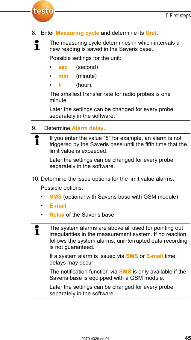
![5 First steps 74 0970 4020 en 01 testo AG 5. Click on [Continue >]. - The settings for measuring cycle, the alarm delay and the alarm issue are shown. 6. Enter the Measuring cycle and determine its Unit. The measuring cycle determines in which intervals a new reading is saved in the Saveris base. Possible settings for the unit: • sec (second) • min (minute) • h (hour). 7. Determine Alarm delay. If you enter the value "5" for example, an alarm is not triggered by the Saveris base until the fifth time that the limit value is exceeded.](https://usermanual.wiki/Testo-SE-and-KGaA/AMB2520T.manual-2/User-Guide-939158-Page-75.png)
![5 First steps 0970 4020 en 01 75 8. Determine the issue options for the limit value alarms. Possible options: • SMS (optional with Saveris base with GSM module) • E-mail • Relay of the Saveris base. The notification function via SMS is only available if the Saveris base is equipped with a GSM module. 9. Click on [Continue >]. - The wizard is shown with the setting for the start of measurement and the list of the newly registered probes. 10. Postpone the start of measurement, if necessary. 11. Click on [Finish] to complete the startup of the hardware. - A note on the successful configuration of the hardware is shown. 12. Press [OK] to confirm the note. - The new hardware is now ready for operation.](https://usermanual.wiki/Testo-SE-and-KGaA/AMB2520T.manual-2/User-Guide-939158-Page-76.png)
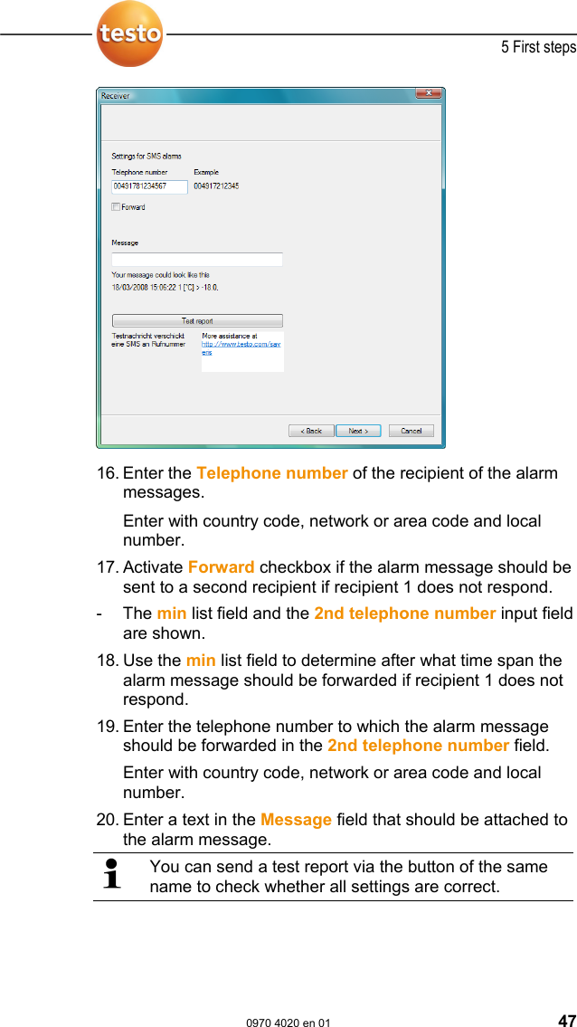
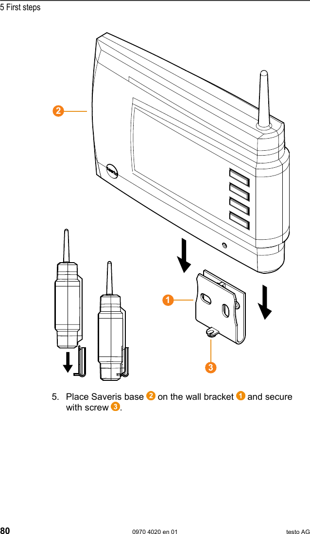
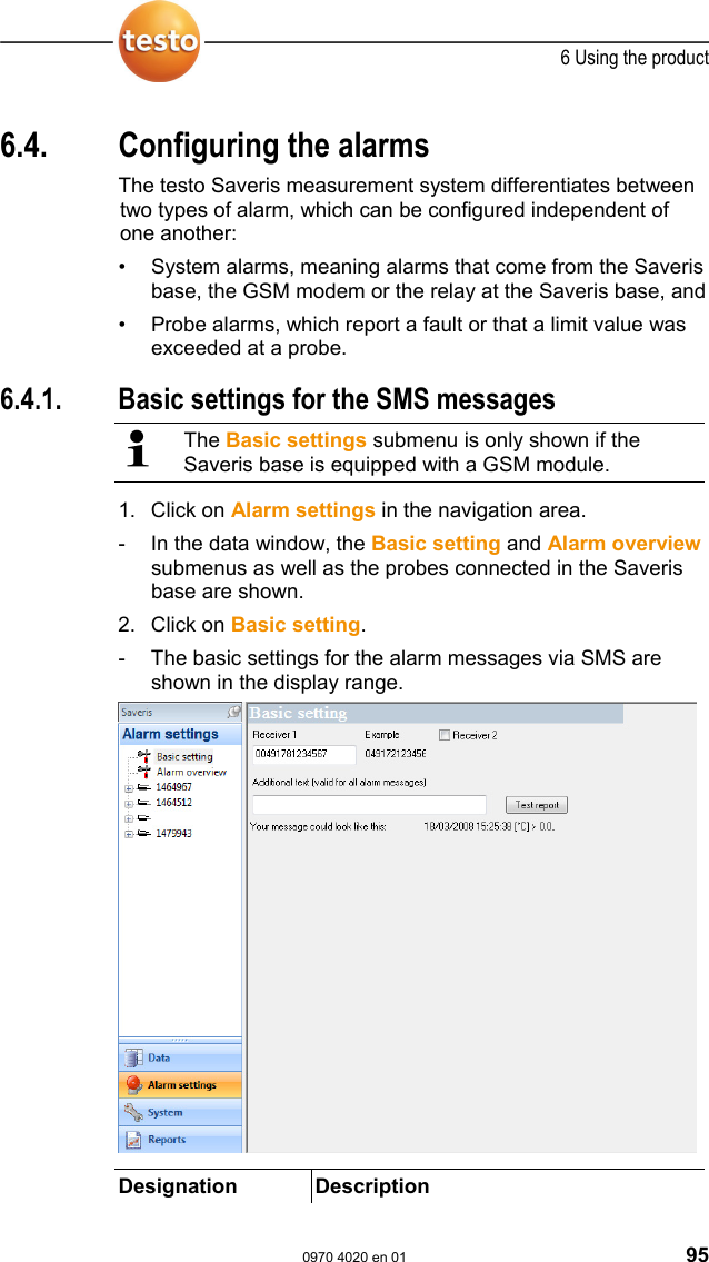
![5 First steps 78 0970 4020 en 01 testo AG 5.13.2. Checking alarm chain You can trigger an alarm and control the sending of the messages without having to bring about a real alarm situation. > Click on Alarms in the navigation area. - In the data window, the Basic setting and Alarm overview submenus as well as the probes connected in the Saveris base are shown. 1. Click on Basic setting. - The basic setting for the alarms is shown in the display range. 2. Click on the [Test report] button. - A test report is sent to the mobile phone number entered. Pos: 86 /TD/Erste Sc hritte/testo Saveris/ 07 **** Montage der Hardw are/00 Hardware montier en @ 0\mod_1189157579984 _79.doc @ 4124](https://usermanual.wiki/Testo-SE-and-KGaA/AMB2520T.manual-2/User-Guide-939158-Page-79.png)
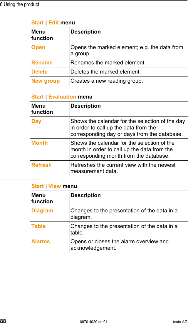
![6 Using the product 0970 4020 en 01 89 6.2.2. Edit Pos: 109 /TD/Produkt verwenden/testo Saver is/02 Menüs und Befehle der Ribbon-Leiste/02 Be arbeiten/02 Bearbeit en (Diagramm) @ 0\mod_118960 6502281_79.doc @ 4555 Edit in the diagram view The Edit (diagram) menu is only shown if the diagram is activated by clicking in the window. Edit | Tools (diagram) menu Menu function Description Zoom in Drag to form a rectangle in the diagram window to zoom in on the highlighted area. Click on [Original size] to display the diagram in its total size again. Crosshairs Crosshairs with which the curve can be followed are shown by clicking on a point of the measurement curve. The date, time, reading number and reading are shown in the process. Mark area You can determine an area that is to be calculated out or saved: The calculation area is determined by clicking on a curve. The area limits can be moved using the left mouse button and the whole area using the right mouse button. • The extract is a time period. If you have determined an extract for a measurement protocol, all calculations are performed within these limits. Remove the extract markings with the Erase text command if you wish to calculate out the entire data sequence. • Area marking and calculation of mean value. If you have marked an area, the area borders, the arithmetic mean value and the minimum and maximum of the value pattern are shown in the status bar.](https://usermanual.wiki/Testo-SE-and-KGaA/AMB2520T.manual-2/User-Guide-939158-Page-90.png)
![6 Using the product 94 0970 4020 en 01 testo AG 6.3. Creating and deleting zones After you have familiarized yourself with the menus of the Saveris software you can now turn to creating zones, for example to separate the probes according to location. You could perhaps combine probes that are located in store rooms into one zone and probes that are in cold rooms into another. Pos: 122 /TD/Produkt verwenden/testo Saver is/03 Gruppen einric hten/organisieren/0 4 Zonen anlegen @ 0\mod_11890 76726062_79.doc @ 3902 6.3.1. Creating zones 1. Click on Data in the navigation area. - The available zones are shown in the data range. 2. Select the New zone command in the Start | Edit | Organizing menu. - The New zone dialogue is shown. 3. If necessary, deactivate an unneeded channel. At least one channel must be activated. When you create a new zone, create a copy with one or more channels from the Zone0 standard group. 4. In the field of the same name, enter the name of the new zone, e.g. "Store rooms". Assign names for the zones that are not longer than 15 characters. 5. Confirm the entries with [OK]. - The New zone dialogue is closed and the new zone is listed in the tree structure in the data range. Pos: 123 /TD/Produkt verwenden/testo Saver is/03 Gruppen einric hten/organisieren/0 8 Zonen löschen @ 0\mod_1189 076727046_79.doc @ 3922 6.3.2. Deleting zones The Zone0 standard group cannot be deleted. 1. Click on Data in the navigation area. - The available zones are shown in the data range. 2. Mark the zone that is to be deleted in the tree structure. 3. Select the Erase command in the Start | Edit menu. - The zone is deleted without a reference.](https://usermanual.wiki/Testo-SE-and-KGaA/AMB2520T.manual-2/User-Guide-939158-Page-95.png)
![6 Using the product 100 0970 4020 en 01 testo AG 6.5. Analyzing series of measurements You can represent series of measurements as a diagram or a table. > In the Start | View menu, select the • Diagram function if the data should be displayed graphically or • Table function if the data should be displayed as a table. Pos: 132 /TD/Produkt verwenden/testo Saver is/05a Diagramme analy sieren/00 Diagramme @ 0\m od_1188996581406_7 9.doc @ 3484 6.5.1. Diagram view In this view, the readings are shown as line diagrams. In the Start | View menu, the Diagram command is activated. Now you have to select the data record that you wish to display. 1. Select the day or time period in the calendar that should be evaluated. 2. In the tree structure of the data range, open the group that contains the data to be displayed. - The diagram for the selected data is shown. > If necessary, deactivate channels via the checkboxes for the display. You can show or hide the gridlines for the corresponding axis by clicking on the time axis or the value axis. Pos: 133 /TD/Produkt verwenden/testo Saver is/05a Diagramme analy sieren/01 Vergrößer n @ 0\mod_1188996582156_7 9.doc @ 3494 6.5.1.1. Enlarging the view Zoom in on a detail of the diagram to check the behavior of the readings within a specific time span, for example. 1. Click on Edit | Tools | Zoom in. 2. In the diagram, use the left mouse button, pressed and held, to highlight the area that should be shown enlarged. Click on [Original size] and the entire diagram is shown again. Pos: 134 /TD/Produkt verwenden/testo Saver is/05a Diagramme analy sieren/02 Fadenkreuz @ 0\ mod_1188996582421_79. doc @ 3504](https://usermanual.wiki/Testo-SE-and-KGaA/AMB2520T.manual-2/User-Guide-939158-Page-101.png)
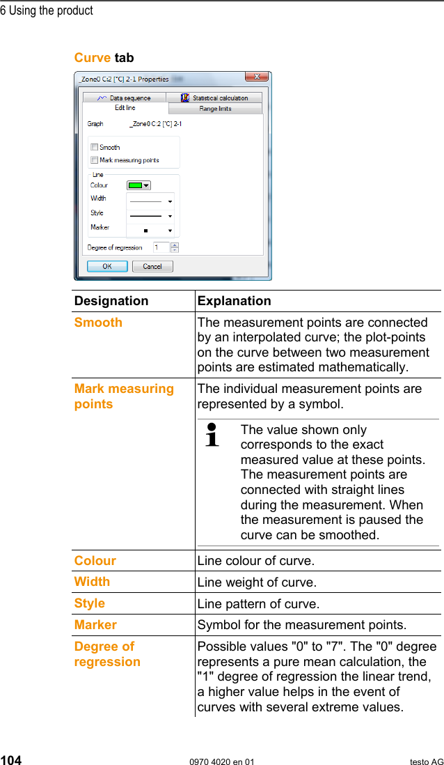
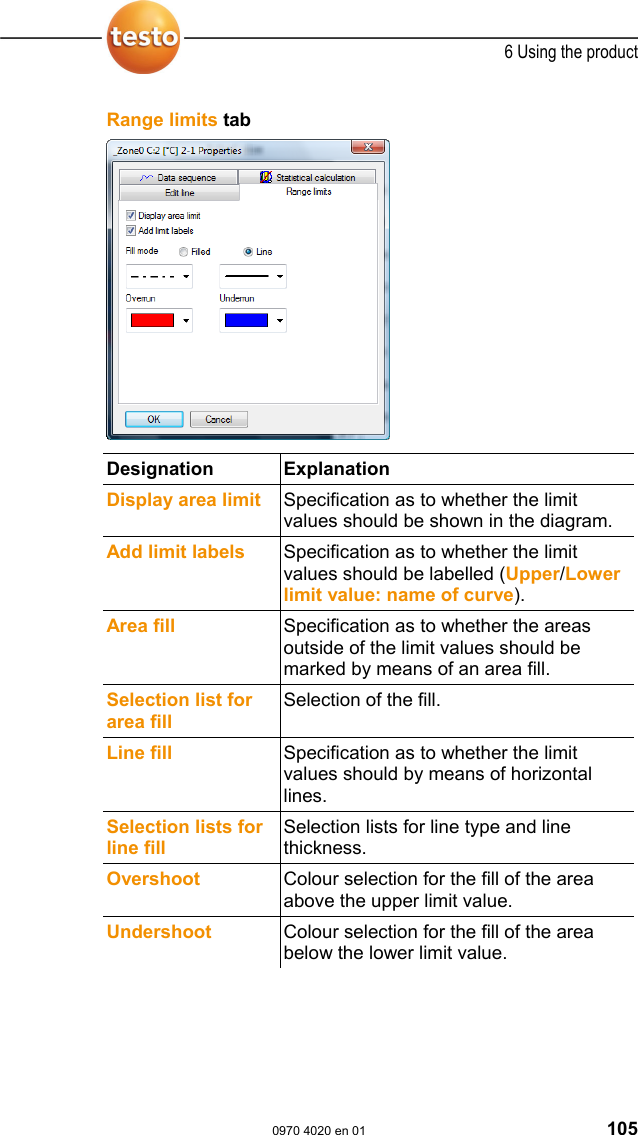
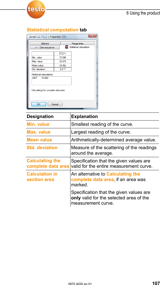
![6 Using the product 0970 4020 en 01 103 6.5.1.6. Erasing text You also delete a marked area from the diagram with the Erase text command. 1. Click on the text that is to be erased. - The text field is marked. 2. Click on Edit | Tools | Erase text. - The text field is deleted. Pos: 139 /TD/Produkt verwenden/testo Saver is/05a-2 Kurveneigensc haften/00 Kur veneigenschaften @ 0\mod_1 188996704171_79.d oc @ 3636 6.5.1.7. Characteristics of a curve You can adapt the representation of a measurement series to your requirements. For example, you can change the line weight of a curve or the representation of the limit values in the diagram. 1. Change to the diagram view of the measurement series, the characteristics of which are to be displayed. 2. Click in the Edit | Curves menu on the entry of the curve, the characteristics of which are to be displayed. - The Characteristics of (name of curve) dialogue is opened. The following tabs are available in the dialogue: • Curve tab • Range limits tab • Data sequence tab • Statistical computation tab. Buttons of the dialogue Button Explanation [OK] Applies the changed settings. The dialogue is closed. [Cancel] Closes the dialogue without applying the changes.](https://usermanual.wiki/Testo-SE-and-KGaA/AMB2520T.manual-2/User-Guide-939158-Page-104.png)
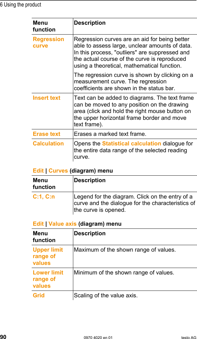
![6 Using the product 106 0970 4020 en 01 testo AG Pos: 142 /TD/Produkt verwenden/testo Saver is/05a-2 Kurveneigensc haften/03 Register Datenreihe @ 0\mod_11 88996704453_79.doc @ 3646 Data sequence tab Designation Explanation Upper limit values Specification of the upper limit value. Lower limit values Specification of the lower limit value. Name Designation of curve. Decimal places number representation Number of the decimal places; e.g. for the data table. Possible values "0" to "6". [Convert unit] Opens a dialogue for converting the unit of the curve. Pie chart Graphical representation for the distribution of the readings: • green: readings that are within the limit values. • blue: readings that are below the lower limit value. • red: readings that are above the upper limit value.](https://usermanual.wiki/Testo-SE-and-KGaA/AMB2520T.manual-2/User-Guide-939158-Page-107.png)
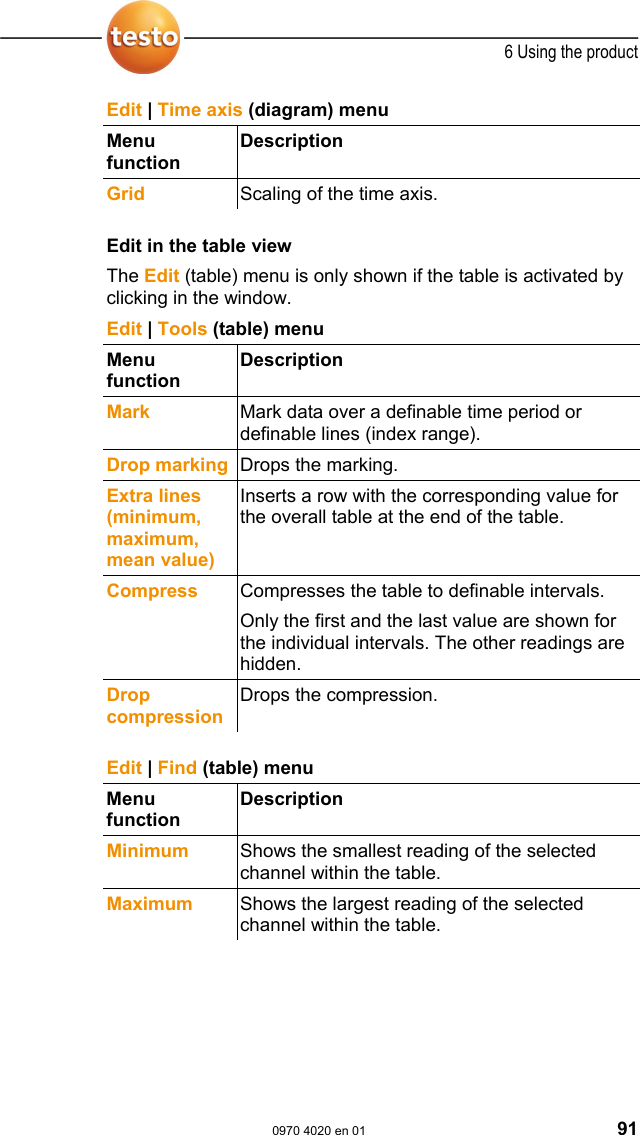
![6 Using the product 108 0970 4020 en 01 testo AG 6.5.1.8. Settings for the axes in the diagram Change the settings of the axes in the diagram to adapt the representation to your requirements. Pos: 145 /TD/Produkt verwenden/testo Saver is/05a-3 Achseins tellungen/06 Wer teachse @ 0\mod_1193999542824_ 79.doc @ 5694 Settings for the value axis > With the right mouse button, click on the desired value axis in the diagram. - The Change axis [unit of the readings] dialogue is shown. Designation Explanation Division linear Specification that the axles are divided in a linear manner. Division logarithmic Specification that the axes are divided logarithmically, meaning the increments represent powers of ten. [OK] Applies the settings until other data are called up. The dialogue is closed. [Cancel] Closes the dialogue without applying any changes. Automatic scale Specification as to whether the program should perform the scaling of the value axis. Range of values from ... to Manual entry of the range of values if the Automatic scale is deactivated. [Store as defaults] Saves the current settings as the default setting. Division Automat. Specification that the program should perform the division of the axis.](https://usermanual.wiki/Testo-SE-and-KGaA/AMB2520T.manual-2/User-Guide-939158-Page-109.png)
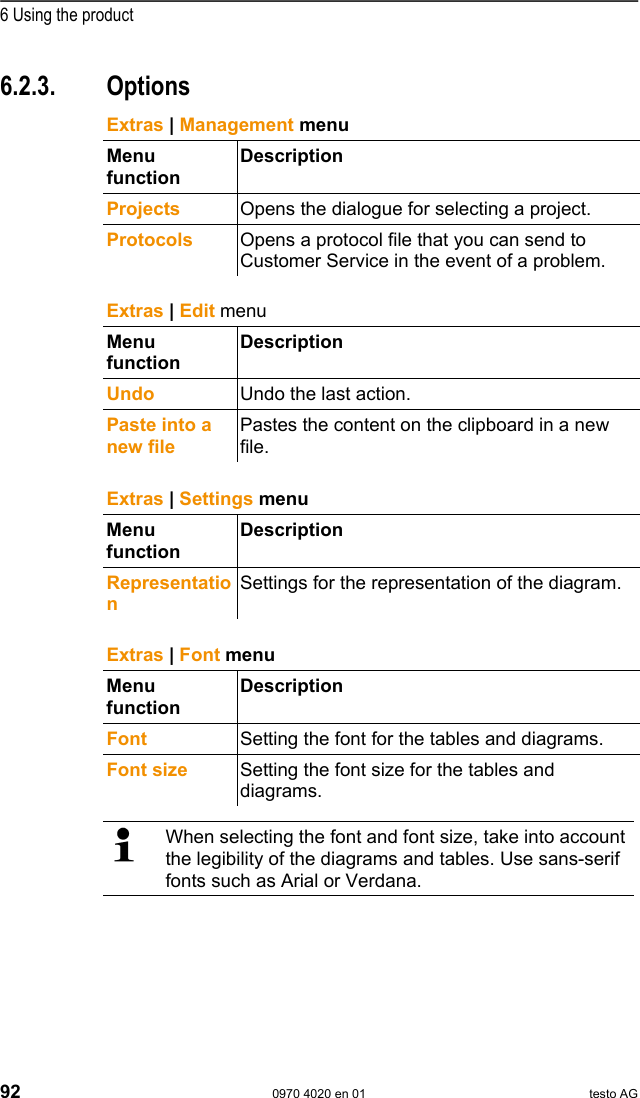
![6 Using the product 0970 4020 en 01 109 Designation Explanation Division Manual Specification that the division of the axis should be performed manually. Grid [<], [>] (if automatic division is activated) Decrease or increase the division of the axis by clicking on [<] or [>]. Interval (if manual division is activated)Manual entry of the grid. Pos: 146 /TD/Produkt verwenden/testo Saver is/05a-3 Achseins tellungen/07 Zeitachs e @ 0\mod_1193999544199_7 9.doc @ 5704 Settings for the time axis > With the right mouse button, click on the time axis in the diagram. - The Adjust time axis dialogue is shown. Designation Explanation [OK] Applies the settings until other data are called up. The dialogue is closed. [Cancel] Closes the dialogue without applying any changes. Position Shows a freely-definable extract of the diagram. Autom. scaling... Shows the entire diagram in the window. Extract Shows a fixed, defined extract that can be moved over the time axis.](https://usermanual.wiki/Testo-SE-and-KGaA/AMB2520T.manual-2/User-Guide-939158-Page-110.png)
![6 Using the product 110 0970 4020 en 01 testo AG Designation Explanation Limits from ... to (if Position view is activated) Limits for the Position view. Minimum time cycle (if Extract view is activated) Specification of which time period should at least be shown. Selection list for the unit (if Extract view is activated) Unit of the time axis in the minimum time cycle: • sec (second) • min (minute) • h (hour) • d (day). Absolute All times are the real times at which the readings were recorded. Relative Sets the starting time to 00:00; the time the runs relative to this starting point. Paging enabled The function associated with this is not available in the Small Business Edition. [Store as defaults] Saves the current settings as the default setting. Division Automat. Specification that the program should perform the division of the axis. Division Manual Specification that the division of the axis should be performed manually. Grid [<], [>] (if automatic division is activated) Decrease or increase the division of the axis by clicking on [<] or [>]. Interval (if manual division is activated)Manual entry of the grid. Selection list for the unit (if manual division is activated)Unit of the time axis: • sec (second) • min (minute) • h (hour) • d (day).](https://usermanual.wiki/Testo-SE-and-KGaA/AMB2520T.manual-2/User-Guide-939158-Page-111.png)
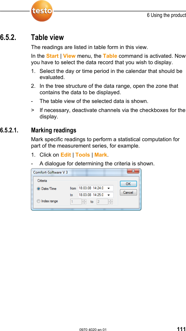
![6 Using the product 112 0970 4020 en 01 testo AG 2. Select the • Select Date/time if the readings for a particular time period are to be marked. - The selection lists are enabled for the determination of the time period. • Select the Index range if the readings in particular rows in the table are to be marked. - The selection lists are enabled for the determination of the index range. 3. Determine time period or index range. 4. Click on [OK]. - The dialogue is closed and the corresponding readings are marked in the table. You can also mark readings with the mouse, as you are familiar with from Office applications. Pos: 149 /TD/Produkt verwenden/testo Saver is/05b Tabellen ana lysieren/02 Markierung a ufheben @ 0\mod_1188996 637078_79.doc @ 3575 6.5.2.2. Dropping the marking > Click on Edit | Tools | Drop marking. - The marking of the readings is deleted. Pos: 150 /TD/Produkt verwenden/testo Saver is/05b Tabellen ana lysieren/03 Extremwert o der Mittelwert einfüg en @ 0\mod_11889966378 90_79.doc @ 3585 6.5.2.3. Inserting extreme values or mean in the table Insert the minimum/maximum reading as well as the mean from the whole table at the end of the table. 1. Click on Edit | Tools | Extra lines | Minimum, Maximum or Mean value. - A row with the corresponding value for all readings is inserted at the end of the table. > Repeat step 1 to insert another value in the table. To erase a value from the table again, click in the Extra lines menu again on the corresponding entry. Pos: 151 /TD/Produkt verwenden/testo Saver is/05b Tabellen ana lysieren/04 Verdic hten @ 0\mod_1188996638437_ 79.doc @ 3595](https://usermanual.wiki/Testo-SE-and-KGaA/AMB2520T.manual-2/User-Guide-939158-Page-113.png)
![6 Using the product 0970 4020 en 01 113 6.5.2.4. Compressing readings Compress the table to definable intervals to maintain the clarity of the table with large amounts of data. Only the first and the last value are shown for the individual intervals. The other readings are hidden. In addition, the minimum, maximum and/or average value can be shown for the respective time period. 1. Click on Edit | Tools | Compress. - The dialogue for determining the options is opened. > Use the checkboxes to determine whether the respective minimum reading (Min), maximum reading (Max) and/or average value (Mean) should be calculated for the individual time spans. At least one of these values must be activated to be able to perform the compression of the table. 2. Enter the time span under Extract and determine its unit. Possible settings for the unit: • sec (second) • min (minute) • h (hour) • d (day). 3. Click on [OK]. - The dialogue is closed and the table is shown compressed. Pos: 152 /TD/Produkt verwenden/testo Saver is/05b Tabellen ana lysieren/05 Verdic htung aufheben @ 0\mod_11889 96639140_79.doc @ 3605](https://usermanual.wiki/Testo-SE-and-KGaA/AMB2520T.manual-2/User-Guide-939158-Page-114.png)
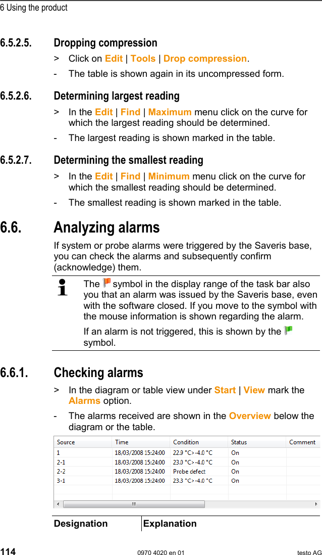
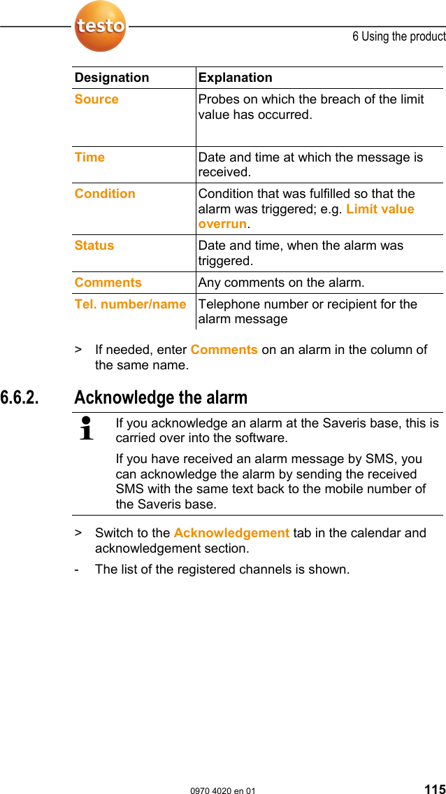
![6 Using the product 0970 4020 en 01 117 5. Mark the entry of the alarm that should be acknowledged. 6. If needed, enter Comments on the alarm in the field of the same name and confirm the alarm with [OK]. - The symbol shows that the alarm was confirmed and the comments are carried over in the alarm list in the display range. The confirmation of the alarm is transmitted to the Saveris base. As soon as the confirmation is received in the Saveris base, the alarm relay stops flashing and the alarm is deleted. Pos: 158 /TD/Produkt verwenden/testo Saver is/07 Berichte/00 Ber ichte erstellen @ 0\mod _1190280535671_79.doc @ 5032 6.7. Creating evaluations You can print out series of measurements or have reports on the data automatically created by the software in definable intervals. Pos: 159 /TD/Produkt verwenden/testo Saver is/07 Berichte/01 Ber icht drucken @ 0\mod_1189522 120546_79.doc @ 4294 6.7.1. Printing measurement data Measurement data can be printed in diagram or table form. 1. Select the day or time period in the calendar for which the report should be created. - The data for the day or the time period are shown as a diagram or table, depending on the setting. > In the Start | View menu, select the • Diagram command if the table view is activated but the diagram view should be printed. • Table command if the diagram view is activated but the table view should be printed.](https://usermanual.wiki/Testo-SE-and-KGaA/AMB2520T.manual-2/User-Guide-939158-Page-118.png)
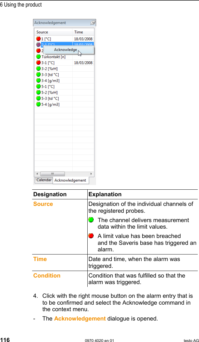
![6 Using the product 118 0970 4020 en 01 testo AG 2. Select the type of report head in the Template | Template menu. Open the preview of the report using the File (Testo logo) | Print preview command. Use portrait format for printing a table and landscape format for printing a diagram. You can determine the format under File | Page Setup.... 3. Select the Print command in the File menu. - The Print dialogue for selecting the printing options is shown. 4. Change printing options, if needed, and click on [OK]. - The report is printed. The report head contains the following information: • title, • number of pages, • date, • start and end time for a measurement (only for tables), • specification of the extreme values and the mean value for every curve, • number of channels and readings (only for tables), • input options for "Conditions" and • other comment lines. Pos: 160 /TD/Produkt verwenden/testo Saver is/07 Berichte/02 * * Automatische Beric hte @ 0\mod_1189522147015_7 9.doc @ 4304 6.7.2. Archiving with automatic reports A simple and secure option for archiving your data is the automatic creation of reports. The reports are created by the software and recorded on a daily, weekly or monthly basis at a specified location on the computer or a server; also see the chapter "Report settings" for this. The reports are saved as PDF files so that they can easily be read or sent per e-mail but without being able to change the data stock.](https://usermanual.wiki/Testo-SE-and-KGaA/AMB2520T.manual-2/User-Guide-939158-Page-119.png)
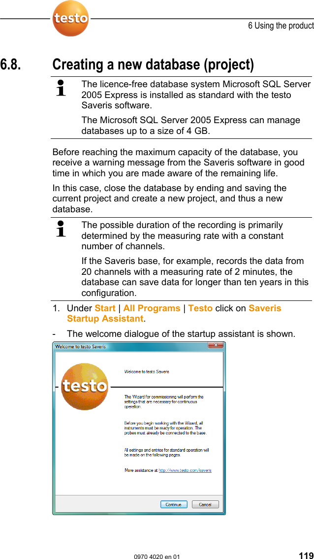
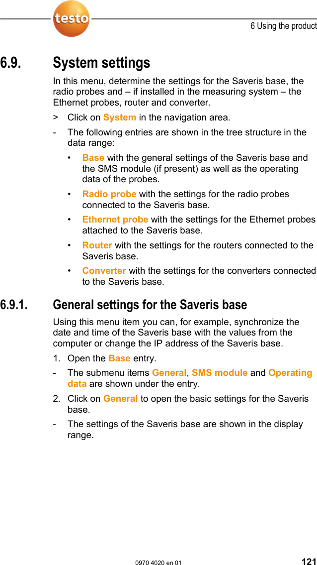
![6 Using the product 120 0970 4020 en 01 testo AG 2. Click on [Continue >]. - The System status dialogue with the General tab is shown. 3. Change to Projects tab. 4. Mark the project that is to be ended and click on [End Measuring Mode]. - A notification is shown in which you must confirm the reset of Saveris base to the basic configuration. 5. Click on [Yes] to reset the Saveris base to the basic configuration. - All components are deleted from the Saveris base and the project is closed in the Saveris software. To be able to start a new project, you must reconnect all components to the Saveris base and then start up the hardware again. Pos: 162 /TD/Produkt verwenden/testo Saver is/09 Einstellungen Sy stem/00 Einstellu ngen System @ 0\mod_11894937 29343_79.doc @ 4233](https://usermanual.wiki/Testo-SE-and-KGaA/AMB2520T.manual-2/User-Guide-939158-Page-121.png)
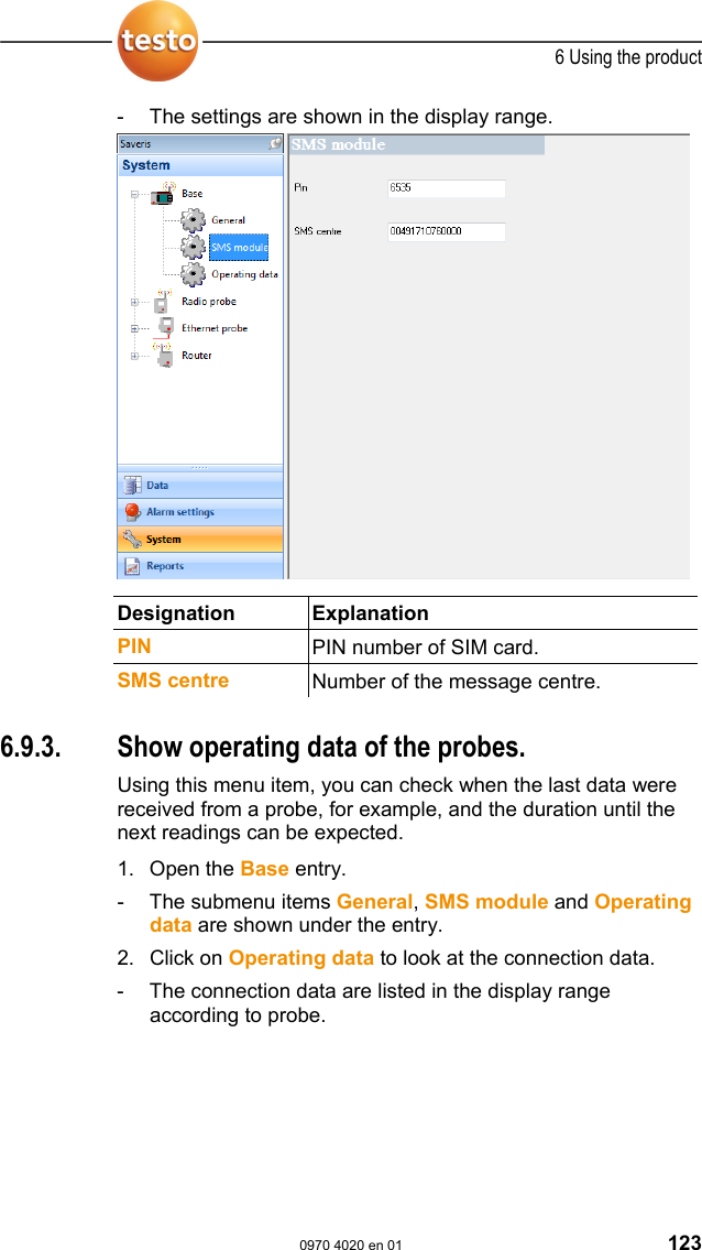
![6 Using the product 122 0970 4020 en 01 testo AG Designation Explanation Serial number Serial number of the Saveris base. Firmware Version number of the instrument software in the Saveris base. Date and time Date and time of the Saveris base. [Synchronize] Date and time from the operating system are applied to the Saveris base. IP address IP address of the Saveris base. Pos: 164 /TD/Produkt verwenden/testo Saver is/09 Einstellungen Sy stem/02 SMS-Modul @ 0\m od_1188997905750_79.d oc @ 3811 6.9.2. System settings for the GSM module Using this menu item, you enter the data of the SIM card and can determine whether the alarm messages are to be sent again if the first attempt at sending them should fail. To be able to use the notification function via SMS you require a Saveris base with an integrated GSM module. 1. Open the Base entry. - The submenu items General, SMS module and Operating data are shown under the entry. 2. Click on SMS module to open the settings for sending the SMS messages.](https://usermanual.wiki/Testo-SE-and-KGaA/AMB2520T.manual-2/User-Guide-939158-Page-123.png)
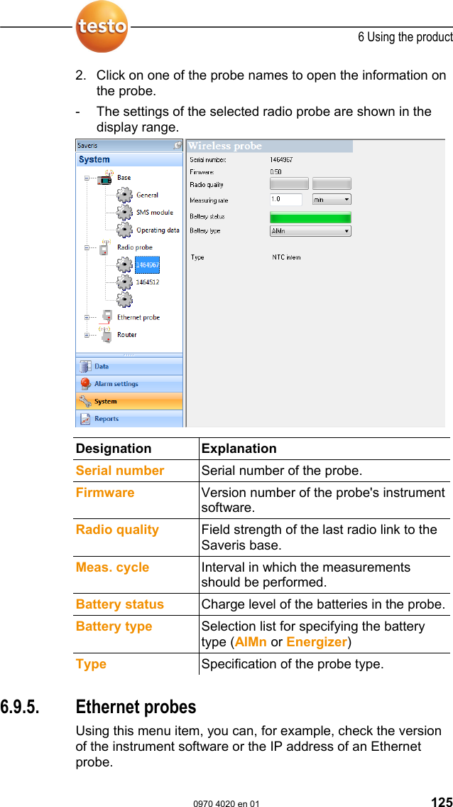
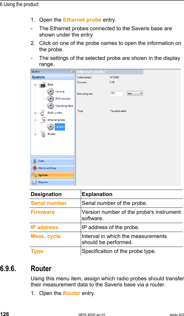
![6 Using the product 124 0970 4020 en 01 testo AG Designation Explanation Serial no. Serial number of the probe _Sync Date and time of the last connection. _SND Date and time when the probe last sent data. _RCV Date and time when the probe last received data. _next Sync Date and time of the next planned connection establishment. _Starttime Date and time of the first measurement of the probe. _Values within [min] Duration in minutes until the probe delivers the next data. Pos: 166 /TD/Produkt verwenden/testo Saver is/09 Einstellungen Sy stem/03 Wireless probe s @ 0\mod_1189598701 171_79.doc @ 4463 6.9.4. Settings for the radio probe Using this menu item you can, for example, check the battery status of the probe or the quality of the radio transmission. 1. Open the Radio probe entry. - The radio probes connected in the Saveris base are listed under the entry.](https://usermanual.wiki/Testo-SE-and-KGaA/AMB2520T.manual-2/User-Guide-939158-Page-125.png)
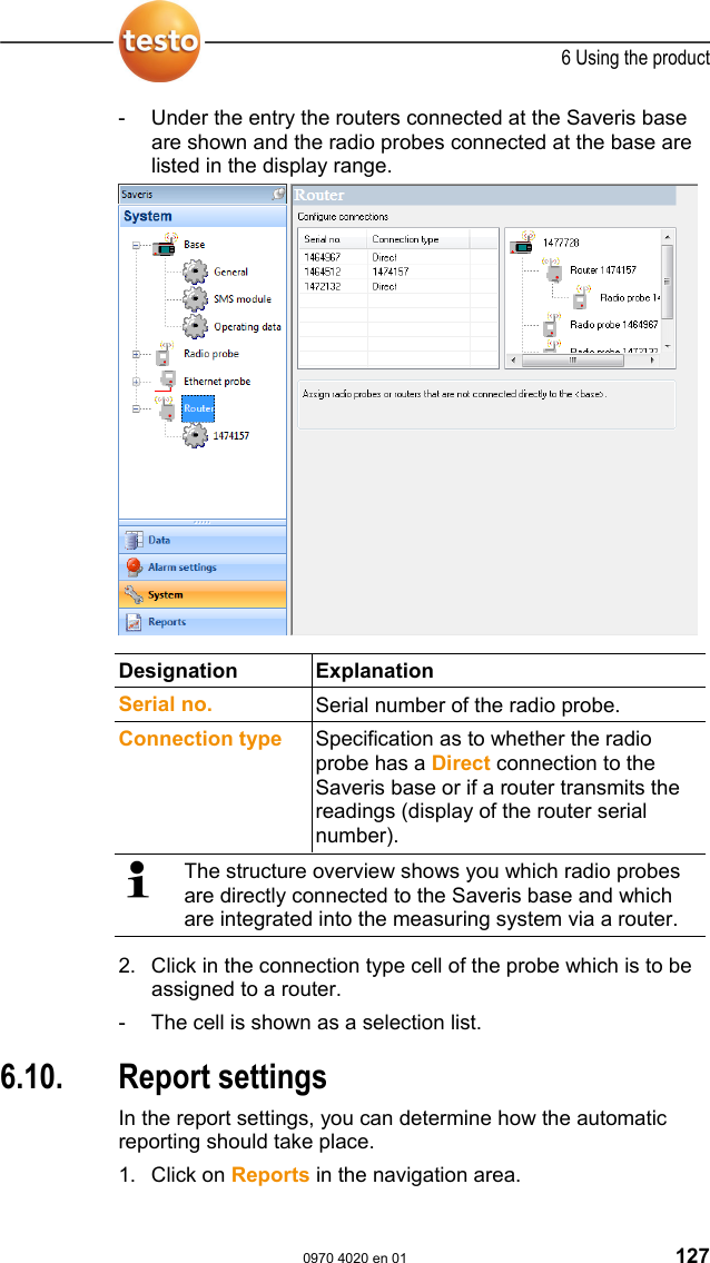
![6 Using the product 128 0970 4020 en 01 testo AG - The Settings for reports submenu is shown in the data window. 2. Click on Settings for reports. - The report settings are shown in the display range. Pos: 170 /TD/Produkt verwenden/testo Saver is/10 Einstellungen Ber ichte/01 Settings @ 0\mod_1188997925140 _79.doc @ 3821 Designation Explanation [New report] Adds a new reporting task to the list. List of the reporting tasks List of the created reporting tasks. Zones Selection list of the group for which the report should be created. Time of the creation Specification as to whether the report should be created Daily, Weekly or Monthly. Daily: The report is created daily at 12 a.m. Weekly: The report is created every Sunday at 12 a.m. Monthly: The report is created on the last day of the month at 12 a.m. Content group field With activated option the corresponding](https://usermanual.wiki/Testo-SE-and-KGaA/AMB2520T.manual-2/User-Guide-939158-Page-129.png)
![6 Using the product 0970 4020 en 01 129 Designation Explanation • Cover page • Graph • Table • Alarms data sheet is attached to the report. Send to receiver option Specification as to whether the report should be sent to an employee by e-mail.If the function is activated, the input fields for the recipient address and the subject line as well as the [Address book] button are shown. Recipient input field Input field for the e-mail address of the employee to whom the report is to be sent. [Address book] Opens the dialogue for the selection of the recipient from the Outlook contact list.Subject Input field for the subject line. Data sheet address field Input field for the address that should be shown on the pages of the report. The storage location for the reports was determined during the installation of the Saveris software. Generally this is C:\Documents and Settings\All Users\Documents\Saveris Small Business Edition. Pos: 171 /TD/--- Seitenwechsel --- @ 0\mod_117 3774430601_0.doc @ 283](https://usermanual.wiki/Testo-SE-and-KGaA/AMB2520T.manual-2/User-Guide-939158-Page-130.png)
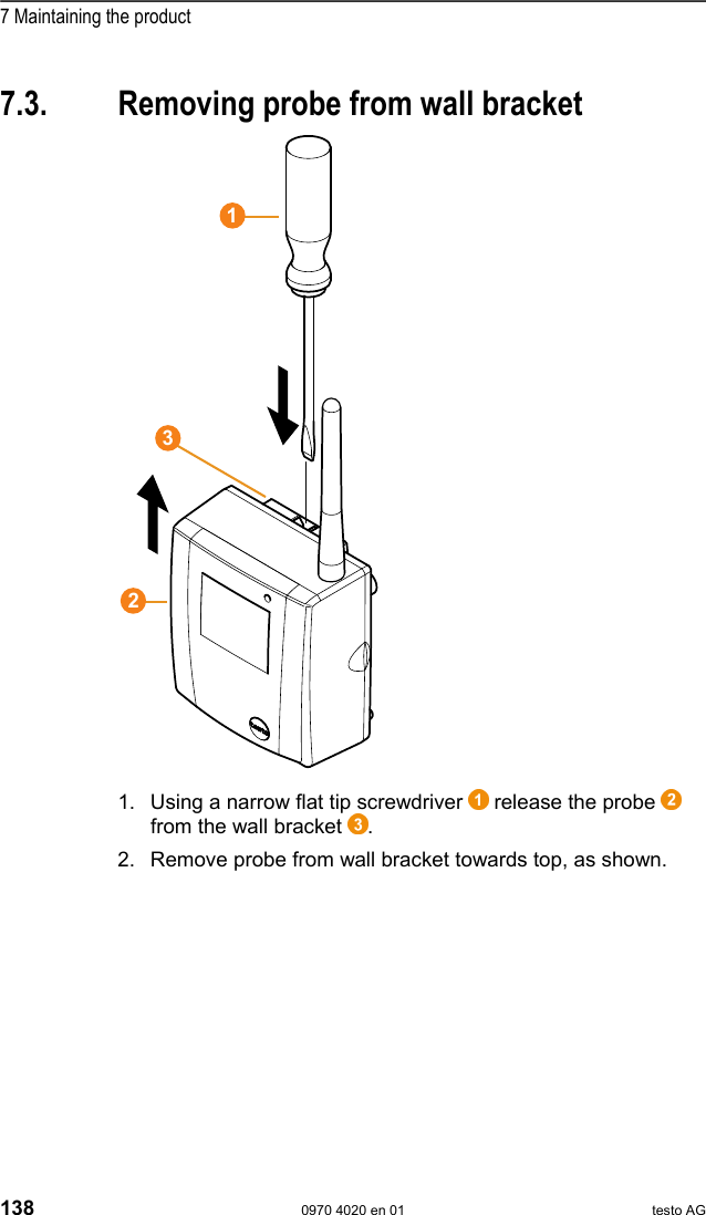
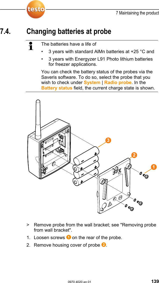
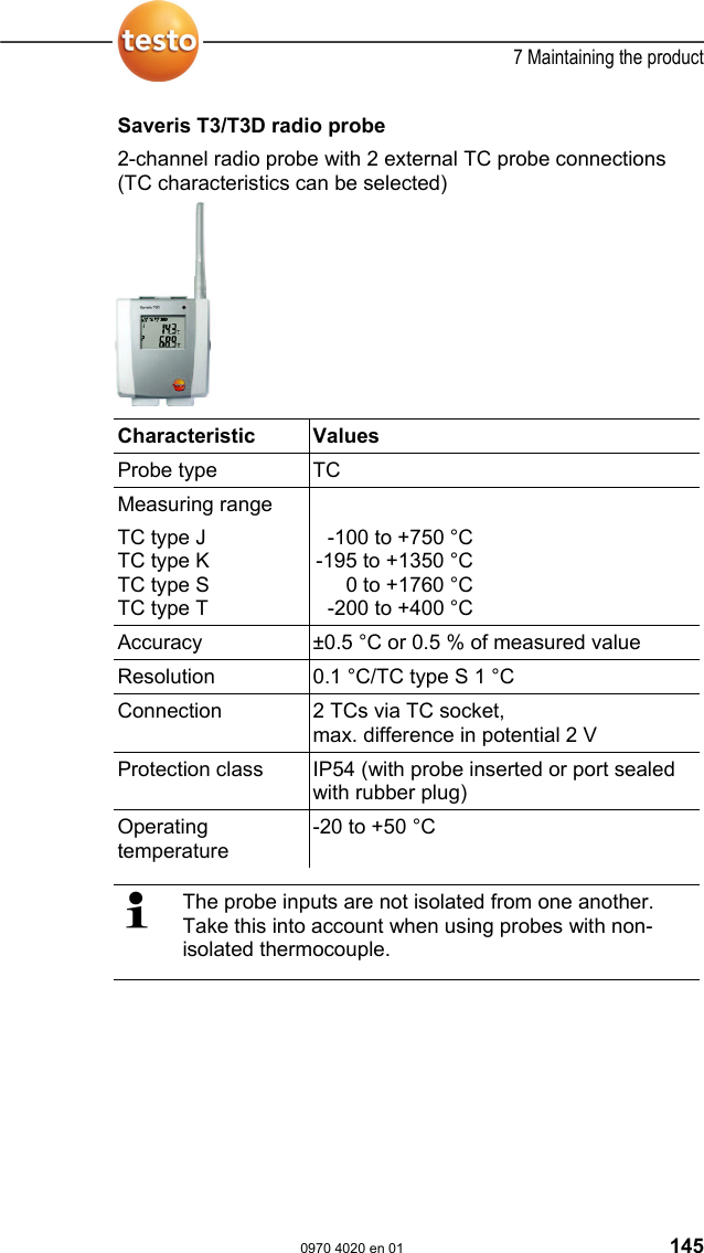
![7 Maintaining the product 130 0970 4020 en 01 testo AG Pos: 172 /TD/Überschr iften/7. Produkt i nstand halten @ 0\mod_117378 9831362_79.doc @ 397 7 Maintaining the product Pos: 173 /TD/Produkt ins tand halten/test o Saveris/00 Ersatz von Ko mponenten @ 0\mod_1188476 464890_79.doc @ 2909 7.1. Replacement of components You can shut down a component – probe, converter or router – at any time because this is temporarily not in use or to replace it with a new component, for example, in the event of a defect. In the event of a replacement of the Saveris base, you must reinstall the software and set up the entire measurement system again. Remember to save the existing measurement data before reinstalling the software. Pos: 174 /TD/Produkt ins tand halten/test o Saveris/01 Komponenten en tfernen @ 0\mod_11937 37448921_79.doc @ 5643 7.1.1. Deleting components 1. Under Start | All Programs | Testo click on Saveris Startup Assistant. - The welcome dialogue of the startup assistant is shown. 2. Click on [Continue >]. - The System status dialogue with the General tab is shown.](https://usermanual.wiki/Testo-SE-and-KGaA/AMB2520T.manual-2/User-Guide-939158-Page-131.png)
![7 Maintaining the product 0970 4020 en 01 131 3. Change to Projects tab. 4. Click on [Log out component]. - The Log out component dialogue is shown. 5. Activate the checkbox in front of the component that is to be logged out of the system. 6. Click on [OK]. - A query to erase the components from the configuration is shown. 7. Confirm the query with [Yes]. - The component is deleted from the configuration. > After deleting a probe, briefly press the connect button on the rear of the probe so that the probe no longer attempts to send measurement data.](https://usermanual.wiki/Testo-SE-and-KGaA/AMB2520T.manual-2/User-Guide-939158-Page-132.png)
![7 Maintaining the product 132 0970 4020 en 01 testo AG Pos: 175 /TD/Produkt ins tand halten/test o Saveris/02 Komponenten hi nzufügen @ 0\mod_1188 476503984_79.doc @ 2918 7.1.2. Adding components 1. Connecting new probes at the Saveris base; see "Connecting radio probe". 2. Start up testo Saveris software. - The software recognizes that a new probe is located in the system and the wizard for the installation of a new component is started. 3. Click on [Continue >]. - The Commission new probe dialogue is shown.](https://usermanual.wiki/Testo-SE-and-KGaA/AMB2520T.manual-2/User-Guide-939158-Page-133.png)
![7 Maintaining the product 0970 4020 en 01 133 4. Leave default setting and click on [Continue >]. - The list of the probes newly registered in the Saveris base is shown.](https://usermanual.wiki/Testo-SE-and-KGaA/AMB2520T.manual-2/User-Guide-939158-Page-134.png)
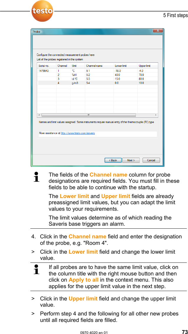
![7 Maintaining the product 134 0970 4020 en 01 testo AG The fields of the Channel name column for probe designations are required fields. You must fill in these fields to be able to continue with the startup. The Lower limit and Upper limit fields are already preassigned limit values, but you can adapt the limit values to your requirements. The limit values determine as of which reading the Saveris base triggers an alarm. 5. Click in the Channel name field and enter the designation of the probe, e.g. "Room 4". > Click in the Lower limit field and change the lower limit value. If all probes are to have the same limit value, click on the column title with the right mouse button and then click on Apply to all in the context menu. This also applies for the upper limit value in the next step. > Click in the Upper limit field and change the upper limit value. > Click in the TC type field and enter the type of thermocouple if this information is required for the instrument. > Perform step 4 and the following for all other new probes until all required fields are filled. 6. Click on [Continue >]. - The settings for measuring cycle, the alarm delay and the alarm issue are shown.](https://usermanual.wiki/Testo-SE-and-KGaA/AMB2520T.manual-2/User-Guide-939158-Page-135.png)
![7 Maintaining the product 0970 4020 en 01 135 7. Enter the Measuring cycle and determine its Unit. The measuring cycle determines in which intervals a new reading is saved in the Saveris base. Possible settings for the unit: • sec (second) • min (minute) • h (hour). The smallest transfer rate for radio probes is one minute. 8. Determine Alarm delay. If you enter the value "5" for example, an alarm is not triggered by the Saveris base until the fifth time that the limit value is exceeded. 9. Determine in which cases a system alarm should be triggered. 10. Click on [Continue >]. - If a router is connected at the Saveris base the configuration of the connection type for the probes is shown. If no router is connected continue with step 15.](https://usermanual.wiki/Testo-SE-and-KGaA/AMB2520T.manual-2/User-Guide-939158-Page-136.png)
![7 Maintaining the product 136 0970 4020 en 01 testo AG 11. Click in the Connection type cell of the probe which is to be assigned to a router. - The cell is shown as a selection list. 12. Open the selection list via the button and select the router to which the probe is to be assigned. 13. Perform steps 11 and 12 for all remaining probes whose measurement data is to be transmitted to the Saveris base via a router. 14. Click on [Continue >]. - The wizard is shown with the setting for the start of measurement and the list of the newly registered probes.](https://usermanual.wiki/Testo-SE-and-KGaA/AMB2520T.manual-2/User-Guide-939158-Page-137.png)
![7 Maintaining the product 0970 4020 en 01 137 15. Postpone the start of measurement, if necessary. 16. Click on [Finish] to complete the startup of the hardware. - A note on the successful configuration of the hardware is shown. 17. Press [OK] to confirm the note. - The new hardware is now ready for operation. Pos: 176 /TD/Produkt ins tand halten/test o Saveris/Kalibrier ung und Justage @ 0\mod_118 8476360640_79.doc @ 2882 7.2. Calibration and adjustment All testo Saveris probes are adjusted in the factory, which is confirmed by the corresponding adjustment report. You can undertake other calibrations or adjustments on site. The separate Saveris adjustment software is available for this. After successful adjustment, the current adjustment data is stored in the probe. At the same time, the adjustment software and the Saveris software accept this data so that the adjustment histories are available.](https://usermanual.wiki/Testo-SE-and-KGaA/AMB2520T.manual-2/User-Guide-939158-Page-138.png)
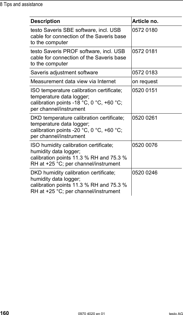
![8 Tips and assistance 0970 4020 en 01 159 computer, the Saveris base can be reconnected with the computer and should then be automatically recognized. 12. How can I change the language for the user guidance at the Saveris base? Disconnect the mains plug of the Saveris base and wait about one minute. After connecting the mains plug, the base shows the language selection. Select the new language and press [Enter] at the Saveris base. The base starts up with the new language setting. 13. After commissioning a probe the reading is outside of the limit values, but no alarm was triggered by the Saveris base. The readings that are recorded from the probe must have already been within the limit values for a breach of the limit values to be recognized by the Saveris base. Pos: 190 /TD/Überschr iften/8.2 Zubehör und Er satzteile @ 0\mod_11774 02058734_79.doc @ 1102 8.2. Accessories and spare parts Pos: 191 /TD/Tipps und Hilfe/Zubehör und Ersa tzteile/testo Saveri s @ 0\mod_1188805346875_7 9.doc @ 3193 Description Article no. Spare batteries for radio probes (4 x AA alkali manganese mignon batteries) 0515 0414 Spare batteries for radio probes for operation below -10 °C (Energyzer L91 Photo lithium) 0515 0572 Mains unit 100 to 200 V DC; for Saveris base, router, converter, Ethernet probe 0554 1096 Mains unit (top-hat rail mounting) 90 to 240 VAC/24 VDC (2.5 A) 0554 1749 Mains unit (desktop instrument) 90 to 240 VAC/24 VDC (350 mA) 0554 1745 Antenna with magnetic base with 3 m cable for base with GSM module 0554 0524 Quad-band antenna 0554 0525 Alarm module (optical & acoustic), can be connected to alarm relay, Ø 700 x 164 mm, 24 V AC/DC/320 mA, steady on: red, steady tone: buzzer approx. 2.4 kHz 0629 6666](https://usermanual.wiki/Testo-SE-and-KGaA/AMB2520T.manual-2/User-Guide-939158-Page-160.png)