Testo SE and KGaA AMB2520T 2.4 GHz Transceiver module User Manual manual 2
Testo AG 2.4 GHz Transceiver module manual 2
Contents
- 1. manual 1
- 2. manual 2
manual 2

Annex No.4b
Page 1 of 164
Functional description / User’s manual
testo Saveris
Measurement data monitoring with testo Saveris
Small Business Edition
Instruction manual
Draft
Demo Unit

2 0970 4020 en 01 testo AG

1 Contents
0970 4020 en 01 3
Pos: 1 /TD/Überschr iften/1. Inhalt @ 0\mod_1 177587817070_79.doc @ 1243
1 Contents
1 Contents .............................................................................................3
2 Safety and the environment ..............................................................7
2.1. About this document ..................................................................7
2.2. Ensure safety.............................................................................8
2.3. Protecting the environment ........................................................9
3 Specifications...................................................................................10
3.1. Use 10
3.2. System requirements ...............................................................12
4 Product description .........................................................................13
4.1. Saveris base ............................................................................13
4.2. Saveris base GSM module (optional) ......................................15
4.2.1. Control keys............................................................................................15
4.2.2. Displays..............................................Fehler! Textmarke nicht definiert.
4.3. Save radio probe......................................................................20
4.3.1. Radio probe without display................Fehler! Textmarke nicht definiert.
4.3.2. Radio probe with display..................... Fehler! Textmarke nicht definiert.
4.3.3. Meaning of the LED displays at the probes.............................................23
4.4. Saveris Ethernet probes ..........................................................24
4.5. Saveris router...........................................................................26
4.6. Saveris converter .....................................................................27
5 First steps.........................................................................................28
5.1. Checking the scope of delivery ................................................28
5.1.1. Set 1 28
5.1.2. Set 2 28
5.1.3. Set 3 29
5.2. Flowchart .................................................................................30
5.3. Inserting SIM card (optional)....................................................32
5.4. Connecting USB cable to the Saveris base .............................33
5.5. Connecting GSM antenna (optional)........................................34
5.6. Connecting Saveris base with power supply............................35
5.6.1. Power supply via mains unit ...................................................................35
5.6.2. Power supply via plug-in/screw connection (optional).............................36

1 Contents
4 0970 4020 en 01 testo AG
5.7. Inserting batteries in the probes...............................................37
5.8. Connecting radio probe....... Fehler! Textmarke nicht definiert.
5.9. Installing Saveris software .......................................................40
5.10. Starting up hardware........... Fehler! Textmarke nicht definiert.
5.11. Starting Saveris software .... Fehler! Textmarke nicht definiert.
5.12. Expand measuring system.......................................................52
5.12.1. Integrating Saveris router (optional)........................................................52
5.12.1.1. Connecting router with power supply (mains unit)...............53
5.12.1.2. Connecting router with power supply (AC/DC)....................54
5.12.1.3. Connecting router ...........Fehler! Textmarke nicht definiert.
5.12.1.4. Assigning probes ............Fehler! Textmarke nicht definiert.
5.12.2. Integrating Saveris Ethernet probe (optional)..........................................61
5.12.2.1. Connecting the network cable.............................................62
5.12.2.2. Connecting Ethernet probe with power supply (mains unit).64
5.12.2.3. Connecting USB cable and installing driver ........................65
5.12.2.4. Installing parameterization software....................................66
5.12.2.5. Assigning connection data ..................................................66
5.12.2.6. Connecting the network cable to the Saveris base..............70
5.12.2.7. Starting up Ethernet probesFehler! Textmarke nicht definiert.
5.12.3. Integrating Saveris converter (optional) ..................................................76
5.13. Performing the test run ............................................................77
5.13.1. Checking system availability...................................................................77
5.13.2. Checking alarm chain ......................... Fehler! Textmarke nicht definiert.
5.14. Mounting the hardware ............................................................79
5.14.1. Mounting the Saveris base on the wall ...................................................79
5.14.2. Setting up Saveris base with stand.........................................................81
5.14.3. Mounting the probe on the wall...............................................................82
5.14.4. Checking the measuring system again ...................................................83
6 Using the product ............................................................................84
6.1. User interface...........................................................................84
6.2. Menus and commands.............................................................86
6.2.1. Start 86
6.2.2. Edit 89
6.2.3. Options 92
6.2.4. Template ................................................................................................93
6.2.5. Style 93
6.2.6. Help (?) 93
6.3. Creating and deleting zones ....................................................94
6.3.1. Creating zones .......................................................................................94
6.3.2. Deleting zones........................................................................................94
6.4. Configuring the alarms.............................................................95
6.4.1. Basic settings for the SMS messages.Fehler! Textmarke nicht definiert.

1 Contents
0970 4020 en 01 5
6.4.2. Configuring the probe alarm ...............Fehler! Textmarke nicht definiert.
6.4.3. Alarm overview ................................... Fehler! Textmarke nicht definiert.
6.5. Analyzing series of measurements ........................................100
6.5.1. Diagram view........................................................................................100
6.5.1.1. Enlarging the view ...................................................................100
6.5.1.2. Information on a reading (crosshairs).......................................101
6.5.1.3. Marking the area......................................................................101
6.5.1.4. Showing regression curve........................................................102
6.5.1.5. Inserting text ............................................................................102
6.5.1.6. Erasing text..............................................................................103
6.5.1.7. Characteristics of a curve ........................................................103
6.5.1.8. Settings for the axes in the diagram.........................................108
6.5.2. Table view ............................................................................................111
6.5.2.1. Marking readings ...................Fehler! Textmarke nicht definiert.
6.5.2.2. Dropping the marking...............................................................112
6.5.2.3. Inserting extreme values or mean in the table..........................112
6.5.2.4. Compressing readings........... Fehler! Textmarke nicht definiert.
6.5.2.5. Dropping compression.............................................................114
6.5.2.6. Determining largest reading.....................................................114
6.5.2.7. Determining the smallest reading.............................................114
6.6. Analyzing alarms....................................................................114
6.6.1. Checking alarms.................................Fehler! Textmarke nicht definiert.
6.6.2. Acknowledge the alarm ......................Fehler! Textmarke nicht definiert.
6.7. Creating evaluations ..............................................................117
6.7.1. Printing measurement data...................................................................117
6.7.2. Archiving with automatic reports ...........................................................118
6.8. Creating a new database (project)Fehler! Textmarke nicht definiert.
6.9. System settings......................................................................121
6.9.1. General settings for the Saveris base. Fehler! Textmarke nicht definiert.
6.9.2. System settings for the GSM module..Fehler! Textmarke nicht definiert.
6.9.3. Show operating data of the probes. .... Fehler! Textmarke nicht definiert.
6.9.4. Settings for the radio probe.................Fehler! Textmarke nicht definiert.
6.9.5. Ethernet probes ..................................Fehler! Textmarke nicht definiert.
6.9.6. Router Fehler! Textmarke nicht definiert.
6.10. Report settings.......................................................................127
7 Maintaining the product ................................................................130
7.1. Replacement of components .................................................130
7.1.1. Deleting components..........................Fehler! Textmarke nicht definiert.
7.1.2. Adding components............................Fehler! Textmarke nicht definiert.
7.2. Calibration and adjustment ....................................................137
7.3. Removing probe from wall bracket.........................................138
7.4. Changing batteries at probe...................................................139

1 Contents
6 0970 4020 en 01 testo AG
7.5. Technical data........................................................................141
7.5.1. Saveris base.........................................................................................141
7.5.2. Saveris radio probe...............................................................................142
7.5.3. Saveris router .......................................................................................148
7.5.4. Saveris Ethernet probes .......................................................................149
7.5.5. Saveris converter..................................................................................154
8 Tips and assistance .......................................................................155
8.1. Questions and answers .........................................................155
8.2. Accessories and spare parts..................................................159
Pos: 2 /TD/--- Seitenwechsel --- @ 0\mod_117377443060 1_0.doc @ 283
2 Safety and the environment
0970 4020 en 01 7
Pos: 3 /TD/Überschr iften/2. Sicher heit und Umwelt @ 0\mod_11737747 19351_79.doc @ 292
2 Safety and the environment
Pos: 4 /TD/Überschr iften/2.1 Zu diesem Doku ment @ 0\mod_117377525235 1_79.doc @ 346
2.1. About this document
Pos: 5 /TD/Sicherhei t und Umwelt/Zu diesem Doku ment/Symbole und Schr eibkonv. [Saveris] @ 0\ mod_1193735939953_79. doc @ 5623
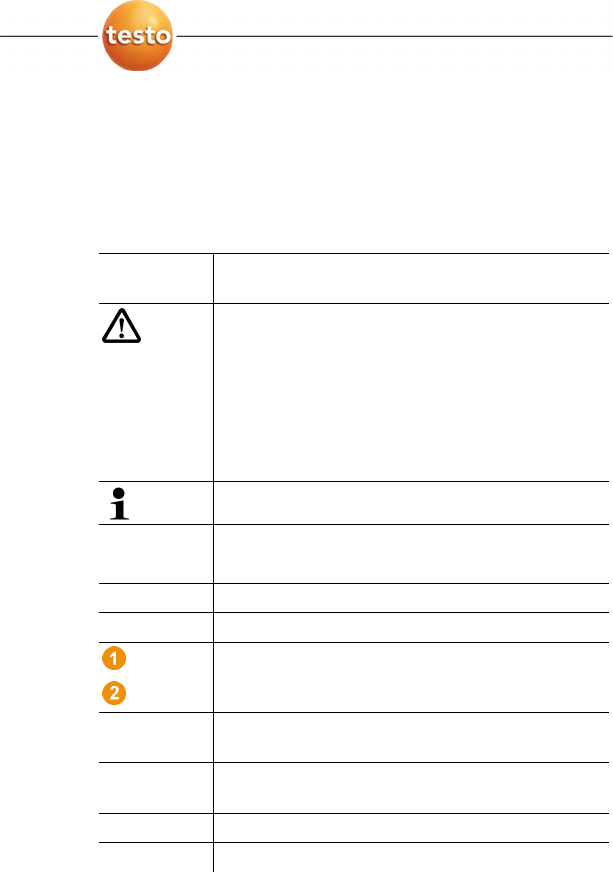
Symbols and writing standards
Representat
ion
Explanation
Warning advice, risk level according to the signal
word:
Warning! Serious physical injury may occur.
Caution! Slight physical injury or damage to the
equipment may occur.
> Implement the specified precautionary
measures.
Note: Basic or further information.
1. ...
2. ...
Action: more steps, the sequence must be
followed.
> ... Action: a step or an optional step.
- ... Result of an action.
...
...
Position numbers for the clarification of the
relationship between text and picture.
Menu Elements of the instrument, the instrument
display or the program interface.
[OK] Control keys of the instrument or buttons of the
program interface.
... | ... Functions/paths within a menu.
“...” Example entries
Pos: 6 /TD/Sicherhei t und Umwelt/Zu diesem Doku ment/Verwendung (Sa veris) @ 0\mod_11913287705 62_79.doc @ 5412

2 Safety and the environment
8 0970 4020 en 01 testo AG
Use
> Familiarity with a PC as well as the Microsoft products,
especially Microsoft Office 2007, is assumed in this
documentation.
> Please read this documentation through carefully and
familiarize yourself with the product before putting it to use.
Pay particular attention to the safety instructions and
warning advice in order to prevent injuries and damage to
the products.
> Keep this document to hand so that you can refer to it when
necessary.
> Hand this documentation on to any subsequent users of the
product.
Pos: 7 /TD/Überschr iften/2.2 Sicher heit gewährleisten @ 0\mod_1173 780783960_79.doc @ 366
2.2. Ensure safety
Pos: 8 /TD/Sicherhei t und Umwelt/Sicherhei t gewährleisten/Sa veris Wartungsarbeite n @ 1\mod_1196958627509_7 9.doc @ 6094
> Carry out only the maintenance and repair work on the
components of the testo Saveris system that is described in
the documentation. Follow the prescribed steps exactly. Use
only original spare parts from Testo.
Pos: 9 /TD/Sicherhei t und Umwelt/Sicherhei t gewährleisten/Sa veris spannungsführ ende Teile @ 1\mod_120490700 8625_79.doc @ 12630
> Never use the Saveris probes to measure on or near live
parts.
Pos: 10 /TD/Sicherhei t und Umwelt/Sicherhei t gewährleisten/Pr odukt bestimmungsge mäß verwenden @ 0\mod_11737812 61848_79.doc @ 386
> Only operate the product properly, for its intended purpose
and within the parameters specified in the technical data. Do
not use any force.
Pos: 11 /TD/Sicherhei t und Umwelt/Sicherhei t gewährleisten/Sa veris Funk @ 1\mod_11981494 59718_79.doc @ 6845
> The output of the power supply for the Saveris probes,
routers, converters and the Saveris base is restricted in
accordance with EN 60950-1:2001. A manipulation of the
power supply is not allowed in terms of the radio
authorization.
> The radio module is installed in the Saveris components
such that the limit values for air and creepage distance is
adhered to with regard to the standards. Changing the
internal design of the components is not allowed.
> When selecting the location, ensure that the permissible
ambient and storage temperatures are adhered to:
• Radio module: -35 to 50°C
• Components: -35 to 50 °C (operation);
-40 to 55 °C (storage).

2 Safety and the environment
0970 4020 en 01 9
Pos: 12 /TD/Überschr iften/2.3 Umwelt schüt zen @ 0\mod_1173780843645 _79.doc @ 375
2.3. Protecting the environment
Pos: 13.1 /TD/Sicher heit und Umwelt/Umwelt sc hützen/Akkus/Bat terien entsorgen @ 0\mod _1175693637007_79.doc @ 619
> Dispose of faulty rechargeable batteries/spent batteries in
accordance with the valid legal specifications.
Pos: 13.2 /TD/Sicher heit und Umwelt/Umwelt schü tzen/Produkt entsor gen @ 0\mod_11737803070 72_79.doc @ 357
> At the end of its useful life, send the product to the separate
collection for electric and electronic devices (observe local
regulations) or return the product to Testo for disposal.
Pos: 14 /TD/--- Seitenwechsel --- @ 0\mod_1173774430601_0.doc @ 283
3 Specifications
10 0970 4020 en 01 testo AG
Pos: 15 /TD/Überschr iften/3. Leistungs beschreibung @ 0\mod_11737 74791554_79.doc @ 301
3 Specifications
Pos: 16 /TD/Überschr iften/3.1 Verwendung @ 0\mod_1176211016437_ 79.doc @ 695
3.1. Use
Pos: 17 /TD/Leistungsb eschreibung/Ver wendung/testo Saver is/01 Einsatzgebiete @ 1\ mod_1197376440546_79. doc @ 6184
Areas of application
The testo Saveris measurement system can be used
everywhere where temperature and humidity-sensitive products
are produced and stored, for example in the food industry (cold
rooms, deep freeze rooms and refrigeration chambers), in
smaller companies in food production, as well as bakeries and
butchers, or in the pharmaceuticals industry (temperature-
controlled cabinet, storage of drugs).
But the measurement system can also be used in other
industries for monitoring the building air conditioning as well as
for quality assurance in store rooms for products in every phase
of production.
The testo Saveris measurement system is only used to
monitor readings, not to control and regulate them.
Pos: 18 /TD/Leistungsb eschreibung/Ver wendung/testo Saver is/02 Funktionsweise @ 1\ mod_1197376538421_79. doc @ 6194
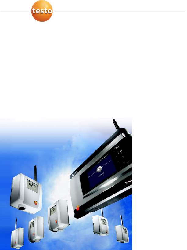
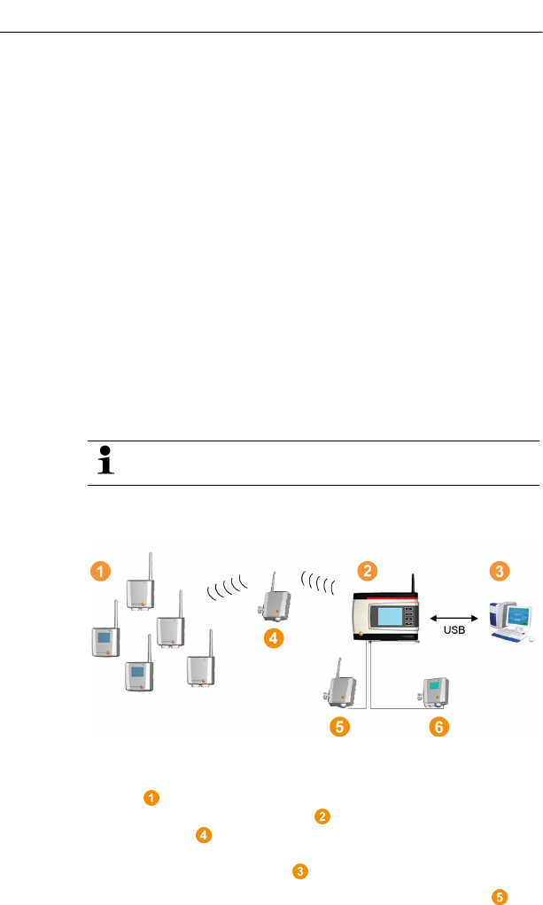
How it works
Pos: 19 /TD/Leistungsb eschreibung/Ver wendung/testo Saveris/ 02b Funktionsweise SBE @ 1\mod_11 97980459890_79.doc @ 6553
Pos: 20 /TD/Leistungsb eschreibung/Ver wendung/testo Saver is/02c Funktionsweise @ 1\mod_1197980516265 _79.doc @ 6573
The ambient or process data for the temperature and air
humidity in closed rooms are measured and recorded using
probes with the measuring system. These readings are
transmitted to the Saveris base via radio, which then saves
them. A router can be used to optimize the radio in the event
of difficult structural conditions. The data are called up from the
Saveris base by a computer and saved in a database.
Very long distances can be bridged by using a converter that
converts the radio signals of the probe or router and then

3 Specifications
0970 4020 en 01 11
transmits these measurement data to the base via Ethernet
cable. In addition the so-called Ethernet probes can be
connected to the base using an Ethernet cable.
With the testo Saveris software you thereby always have an
overview of the development of the readings in the individual
areas.
Pos: 21 /TD/Leistungsb eschreibung/Ver wendung/testo Saver is/04 Haftungsaussc hluss @ 1\mod_119737661 6906_79.doc @ 6214
Exclusion of liability
The testo Saveris system was developed to consolidate a large
amount of measurement data from spatially separated probes in
the Saveris software, document it without interruption and issue
alarms in the event of irregularities.
The testo Saveris system is not designed to undertake control
and regulation tasks according to the regulations. Particularly
the alarms are not to be perceived as so-called critical alarms
with which the endangerment of life or limb or damage to
equipment can be averted.
Liability on the part of Testo AG for damages from this type of
application is excluded.
Pos: 22 /TD/Überschr iften/3.2 Systemvorau ssetzungen @ 0\mod_118 7269645125_79.doc @ 2385

3 Specifications
12 0970 4020 en 01 testo AG
3.2. System requirements
Pos: 23 /TD/Leistungsb eschreibung/Sy stemvoraussetzungen/ Betriebssyste m (Saveris) @ 0\mod_119191 7806171_79.doc @ 5423
Operating system
The software can be run on the following operating systems:
• Windows® 2000 SP4
• Windows® XP SP2
• Windows® Vista
Pos: 24 /TD/Leistungsb eschreibung/Sy stemvoraussetzungen/ Rechner (Saveris) @ 0\mod_1191918060734_79. doc @ 5433
Computer
For smooth work with the software, the following requirements
should be met:
• Pentium processor of at least 800 MHz or equivalent
• 256 MB RAM
• 4.5 GB unused hard drive capacity with maximum size of
the database
• CD-ROM or DVD-ROM drive
• USB 2.0 interface
• Microsoft® Internet Explorer 6.0 SP1 or higher
• Microsoft® Windows Installer 3.1 or higher
• MDAC 2.8 SP1 or higher
• .NET Framework 2.0 or higher
If Windows® Installer 3.1, MDAC 2.8 SP1 and .NET
Framework 2.0 are not present on the computer, these
are installed with the Saveris software.
• Microsoft® Outlook
If you use Lotus Notes, you must set up the adapter for
the Exchange Server. If necessary, consult with your
system administrator.
Pos: 25 /TD/--- Seitenwechsel --- @ 0\mod_1173774430601_0.doc @ 283
4 Product description
0970 4020 en 01 13
Pos: 26 /TD/Überschr iften/4. Produktbesc hreibung @ 0\mod_1173 774846679_79.doc @ 310
4 Product description
Pos: 27 /TD/Produktb eschreibung/Übersic ht/testo Saveri s/Hinweis CE @ 1\mod_120490 5902234_79.doc @ 12612
As declared in the declaration of conformity, this
product complies with Directive 2004/108/EC.
Pos: 28 /TD/Produktb eschreibung/Übersic ht/testo Saveri s/00 Base/01 Base @ 0\mod_118 9504245140_79.doc @ 4274
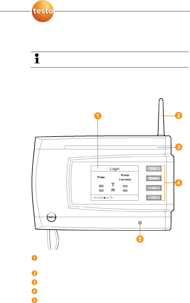
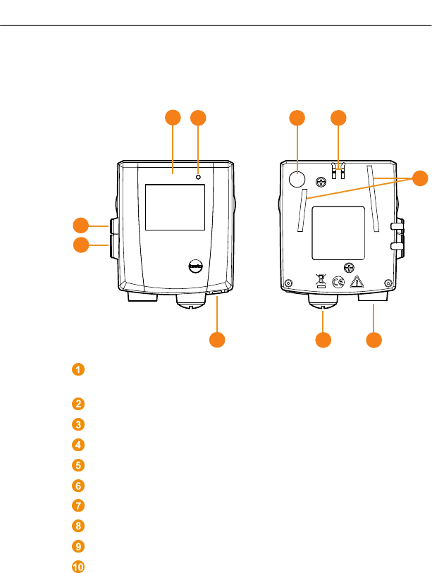
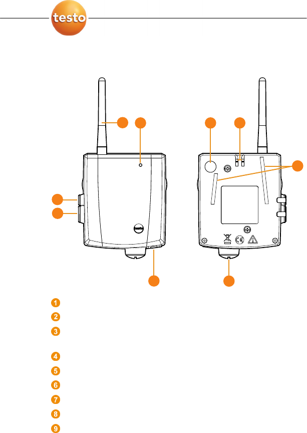
4.1. Saveris base
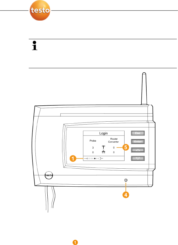
Front
Display for the visualization of the alarms and user
guidance.
Antenna.
Warning LED
Keypad for operation of the Saveris base.
LED for status display.
4 Product description
14 0970 4020 en 01 testo AG
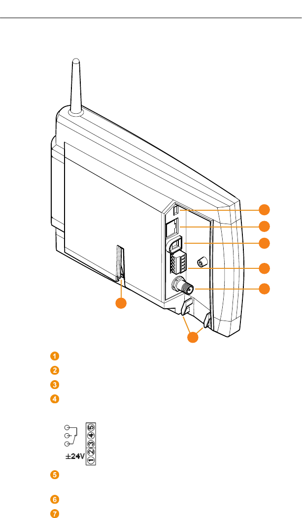
Rear
USB cable connection.
Network cable connection.
Connection of power supply via mains plug.
Connection of power supply via 24 V AC/DC and alarm
relay.
Connection for external GSM antenna (only in combination
with GSM module).
Eyelets for strain relief.
Guide for stand or wall bracket.
1
2
3
4
5
6
7
4 Product description
0970 4020 en 01 15
Pos: 29 /TD/Produktb eschreibung/Übersic ht/testo Saveri s/00 Base/02 Base GSM @ 1\mod_1 196957066669_79.doc @ 6084
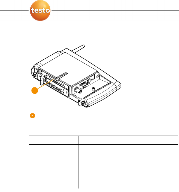
4.2. Saveris base GSM module (optional)
Insertion slot for the SIM card.
Pos: 30 /TD/Produktb eschreibung/Übersic ht/testo Saveri s/00 Base/Bedientast en @ 0\mod_1190205422265_ 79.doc @ 4893
4.2.1. Control keys
Key Explanation
[Esc] Switches from the Login menu to the
Info System menu.
[Enter] In the Info System menu starts up the
login status for the probe.
[ ▲ ], [ ▼ ] Navigation buttons for changing the
menus.
Pos: 31 /TD/Produktb eschreibung/Übersic ht/testo Saveri s/00 Base/Displayanzei gen @ 0\mod_1190205462 296_79.doc @ 4902
*
4 Product description
16 0970 4020 en 01 testo AG
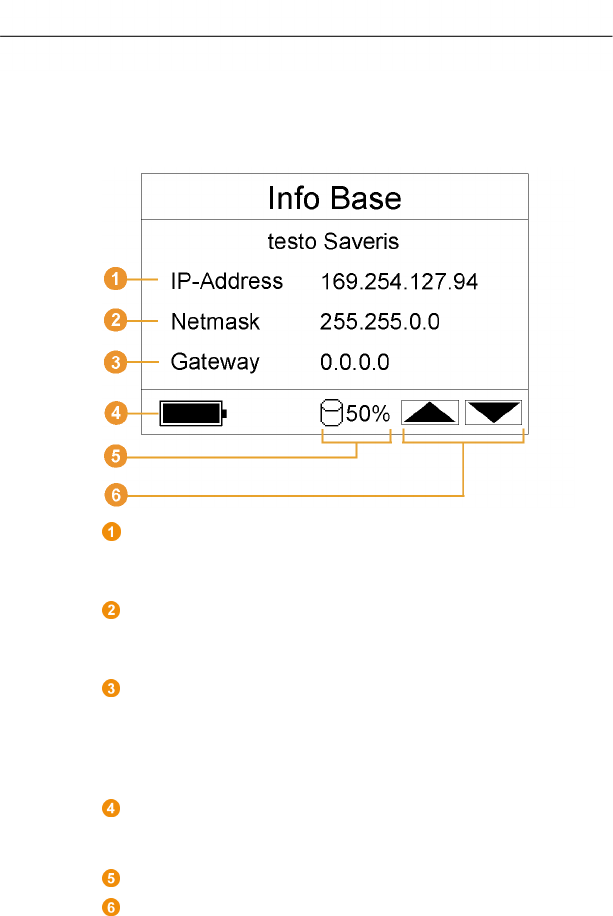
4.2.2. Displays
Info Base menu
IP address of the Saveris base.
The IP address is the unique identification number of the
Saveris base within the network.
Netmask that is saved in the Saveris base.
The netmask is the basic address of the network in which
the Saveris base is integrated.
Address of the gateway that is saved in the Saveris base.
A gateway is a transfer point between networks that work
with different protocols or data formats. A "translation" into
the respective other protocol or data format is then
performed by the gateway.
Fill level of the internal rechargeable battery in the event of
power failure. The display is only shown with an interrupted
power supply.
Fill level of the memory of the Saveris base.
Keys that are assigned functions in this menu.
4 Product description
0970 4020 en 01 17
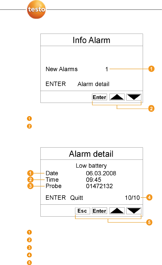
Info Alarm menu
Number of the newly triggered alarms.
Keys that are assigned functions in this menu.
Alarm detail menu
Date on which the alarm was triggered.
Time at which the alarm was triggered.
Probe for which the alarm was triggered.
Number of the alarm and total amount of alarms.
Keys that are assigned functions in this menu.
4 Product description
18 0970 4020 en 01 testo AG
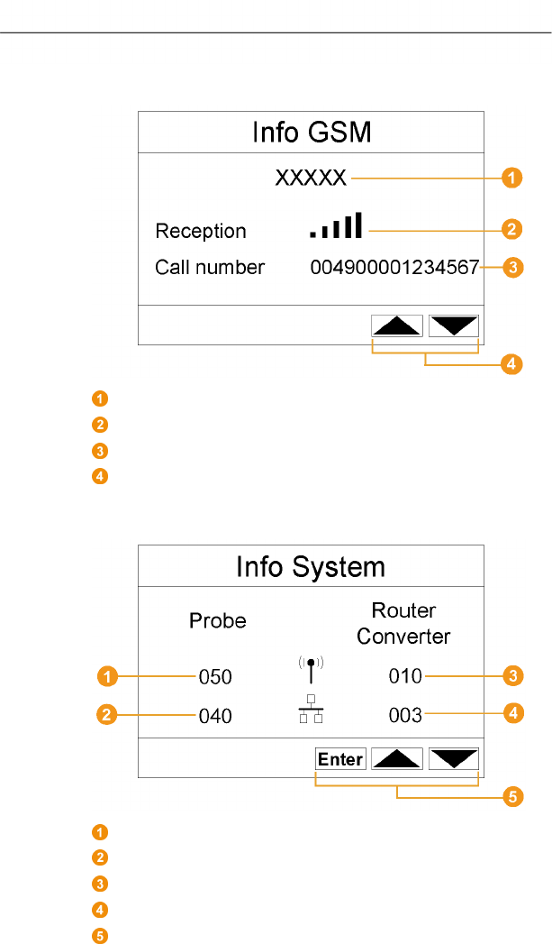
Info GSM menu
Name of the network operator.
Display of the reception quality.
Telephone number that is saved on the SIM card.
Keys that are assigned functions in this menu.
Info System menu
Number of connected radio probes.
Number of connected Ethernet probes.
Number of connected routers.
Number of connected converters.
Keys that are assigned functions in this menu.

4 Product description
0970 4020 en 01 19
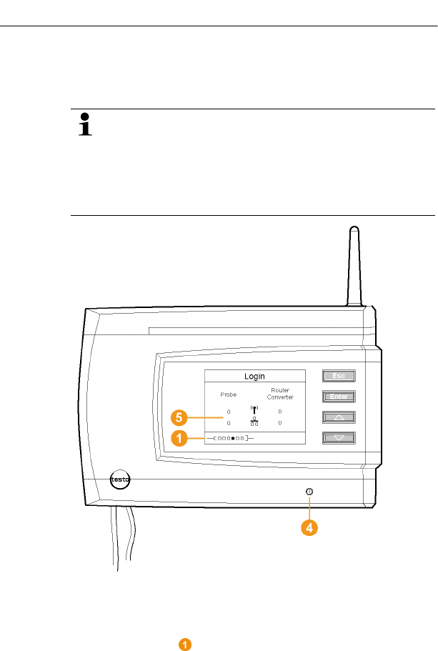
Login 1/2 menu
Status display when probes are connected.
Login 2/2 menu
Keys that are assigned functions in this menu.
This display is shown if no login signal was received
from a probe within approx. 30 seconds.
4 Product description
20 0970 4020 en 01 testo AG
Pos: 32 /TD/Produktb eschreibung/Übersic ht/testo Saveri s/01 Funkfühler/00 Funkf ühler @ 0\mod_119028149 7265_79.doc @ 5041
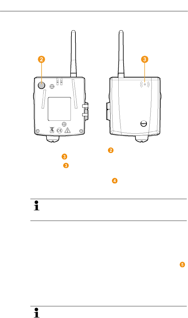
4.3. Save radio probe
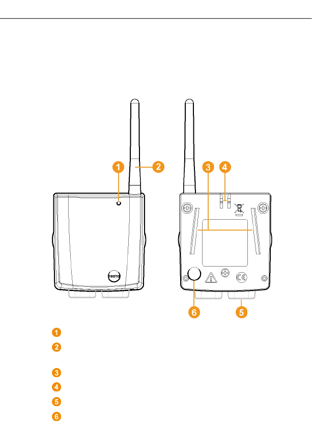
Pos: 33 /TD/Produktb eschreibung/Übersic ht/testo Saveri s/01 Funkfühler/01 Fun kfühler ohne Display @ 0\ mod_1189496319546_79.doc @ 4255
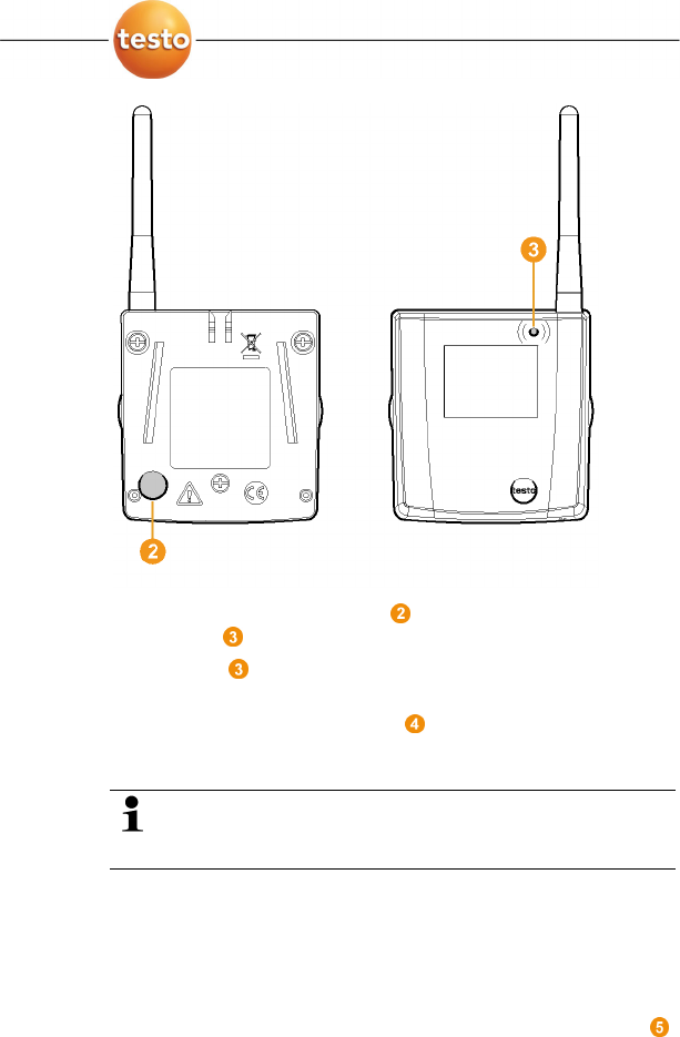
4.3.1. Radio probe without display
LED for status display.
Antenna for radio transmission of measurement data to the
Saveris base.
Guide rails for the wall bracket.
Catch for the wall bracket.
Ports, depending on type.
Connect button for connecting the probe to the Saveris base
and for a status request during operation.
4 Product description
0970 4020 en 01 21
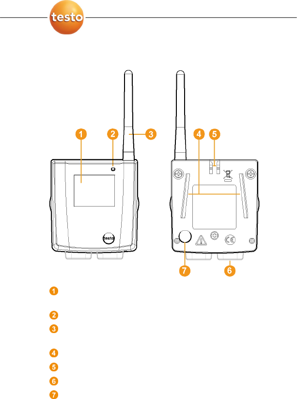
Pos: 34 /TD/Produktb eschreibung/Übersic ht/testo Saveri s/01 Funkfühler/02 Fun kfühler mit Display @ 0\ mod_1189496687343_79.d oc @ 4264
4.3.2. Radio probe with display
Display for showing reading, battery and connection status
as well as the field strength of the radio link.
LED for status display.
Antenna for radio transmission of measurement data to the
Saveris base.
Guide rails for the wall bracket.
Catch for the wall bracket.
Ports, depending on type.
Connect button for connecting the probe to the Saveris base
and for a status request during operation.
4 Product description
22 0970 4020 en 01 testo AG
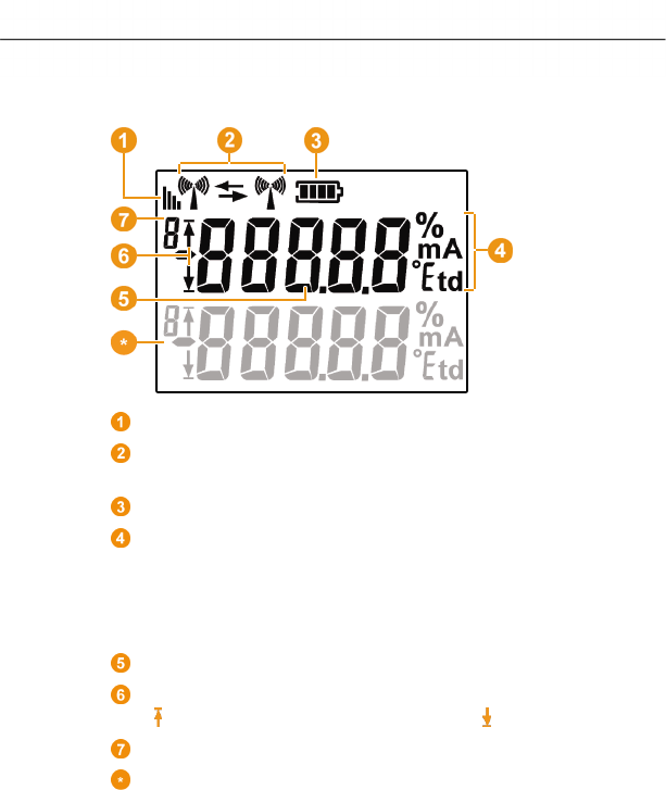
Displays
Quality of the radio link.
Indicator as to whether a communication with the Saveris
base or a router or converter is performed.
Battery status.
Unit of the reading:
• % for humidity measurement
• mA for current measurement
• °Ctd or °Ftd for dewpoint measurement.
Reading.
Indicator as to whether the reading has exceeded the upper
( ) limit value or undershot the lower ( ) limit value.
Number of the channel.
Display for a second sensor in the probe.
Pos: 35 /TD/Produktb eschreibung/Übersic ht/testo Saveri s/01 Funkfühler/03 Bede utung der LED @ 0\mod_1190807 440000_79.doc @ 5133

4 Product description
0970 4020 en 01 23
4.3.3. Meaning of the LED displays at the probes
Connecting to the Saveris base
Hold the connect button on the rear of the probe until the LED
begins to flash orange.
Representation Explanation
Flashing orange An attempt to establish the connection to
the Saveris base.
Lit up green The connection to the Saveris base was
performed successfully.
Lit up red The connection to the Saveris base
failed.
Status displays during operation
Briefly press the connect button on the rear of the probe once
and the LED shows the status of the connection to the Saveris
base.
Representation Explanation
Flashing 3 x green A very good connection to the Saveris
base exists.
Flashing 2 x green A good connection to the Saveris base
exists.
Flashing 1 x green A borderline connection to the Saveris
base exists.
Flashing 3 x red No connection to the Saveris base exists.
4 Product description
24 0970 4020 en 01 testo AG
Pos: 36 /TD/Produktb eschreibung/Übersic ht/testo Saveri s/02 Ethernet-Fühler/ 00 Ethernet-Fühler @ 1\mod_1197555728828_79. doc @ 6366
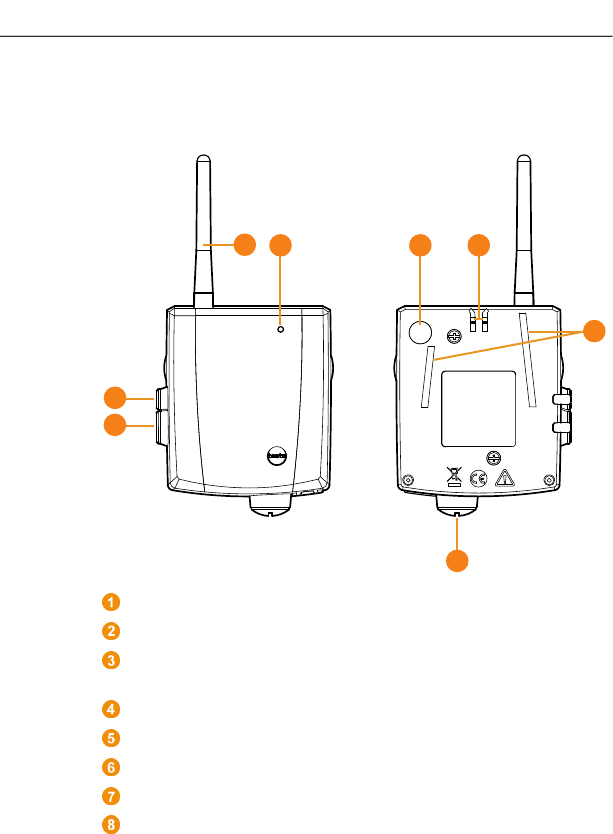
4.4. Saveris Ethernet probes
Pos: 37 /TD/Produktb eschreibung/Übersic ht/testo Saveri s/02 Ethernet-Fühler/ 02 Ethernet-Fühler @ 1\mod_1197555730062_79. doc @ 6386
Display for showing the reading and transmission
information.
LED for status display.
Connect button.
Catch for the wall bracket.
Guide rails for the wall bracket.
Input for external probes.
Input for external 24 V AC/DC power supply.
Input for Ethernet interface.
Input for service interface.
Input for power supply via mains unit.
123
8
9
10
7
4
5
6
4 Product description
0970 4020 en 01 25
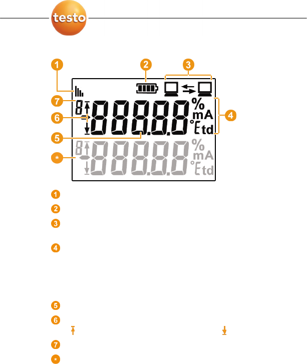
Displays
Quality of the connection.
Battery status.
Indicator as to whether a communication with the Saveris
base is performed.
Unit of the reading:
• % for humidity measurement
• mA for current measurement
• °Ctd or °Ftd for dewpoint measurement.
Reading.
Indicator as to whether the reading has exceeded the upper
( ) limit value or undershot the lower ( ) limit value.
Number of the channel.
Display for a second sensor in the probe.
4 Product description
26 0970 4020 en 01 testo AG
Pos: 38 /TD/Produktb eschreibung/Übersic ht/testo Saveri s/03 Router/01 Router @ 1\ mod_1197555862937_79. doc @ 6406
4.5. Saveris router
Antenna for the radio transmission of the measurement data
LED for status display
Connect button for connecting the router to the Saveris base
and for a status request during operation
Catch for the wall bracket
Guide rails for the wall bracket
Input for external 24 V AC/DC power supply.
Input for service interface
Input for power supply via mains unit
123
7
8
4
5
6
4 Product description
0970 4020 en 01 27
Pos: 39 /TD/Produktb eschreibung/Übersic ht/testo Saveri s/04 Converter/01 Con verter @ 1\mod_119755708 6312_79.doc @ 6416
4.6. Saveris converter
Antenna for receiving the measurement data.
LED for status display.
Connect button for connecting the converter to the Saveris
base and for a status request during operation.
Catch for the wall bracket.
Guide rails for the wall bracket.
Input for external 24 V AC/DC power supply.
Input for connecting the network cable.
Input for service interface.
Input for power supply via mains unit.
Pos: 40 /TD/--- Seitenwechsel --- @ 0\mod_1173774430601_0.doc @ 283
123
7
8
9
4
5
6

5 First steps
28 0970 4020 en 01 testo AG
Pos: 41 /TD/Überschr iften/5. Erste Schr itte @ 0\mod_1173774895039_ 79.doc @ 319
5 First steps
Pos: 42 /TD/Erste Sc hritte/testo Saveris/ 01 Lieferumfang/00 Li eferumfang prüfen @ 0\ mod_1189429809359_79. doc @ 4194
5.1. Checking the scope of delivery
If you have purchased a Saveris set, the following components
are included in the delivery.
Pos: 43 /TD/Erste Sc hritte/testo Saveris/ 01 Lieferumfang/01 Se t 1 @ 0\mod_1189429830390_79. doc @ 4206
5.1.1. Set 1
The following components are included in the delivery of the
first set:
• Product CD with testo Saveris software
• CD with instruction manual in PDF format as well as virtual
installation description
• Printed brief instructions for commissioning
• Saveris Base without GSM module with wall bracket and
stand
• Mains unit for the Saveris base
• 3 Saveris T1 NTC radio probes without display with wall
bracket and batteries
Pos: 44 /TD/Erste Schr itte/testo Saveris/01 Liefer umfang/01 Set 1 SBE @ 1\mod_11979 89725515_79.doc @ 6673
• USB cable for the connection of the Saveris base to the
computer.
Pos: 45 /TD/Erste Sc hritte/testo Saveris/ 01 Lieferumfang/02 Se t 2 @ 0\mod_1189429865593_79. doc @ 4216
5.1.2. Set 2
The following components are included in the delivery of the
second set:
• Product CD with testo Saveris software
• CD with instruction manual in PDF format as well as virtual
installation description
• Printed brief instructions for commissioning
• Saveris Base without GSM module with wall bracket and
stand
• Mains unit for the Saveris base
• Router

5 First steps
0970 4020 en 01 29
• Mains unit for the router
• 5 Saveris T1D NTC radio probes with display and with wall
bracket and batteries
Pos: 46 /TD/Erste Schr itte/testo Saveris/01 Liefer umfang/02 Set 2 SBE @ 1\mod_11979 89908312_79.doc @ 6713
• USB cable for the connection of the Saveris base to the
computer.
Pos: 47 /TD/Erste Sc hritte/testo Saveris/ 01 Lieferumfang/03 Se t 3 @ 0\mod_1191325080125_79. doc @ 5352
5.1.3. Set 3
The following components are included in the delivery of the
third set:
• Product CD with testo Saveris software
• CD with instruction manual in PDF format as well as virtual
installation description
• Printed brief instructions for commissioning
• Saveris base with GSM module and wall bracket, stand and
GSM antenna
The SIM card for sending SMS messages is not
included in the delivery and must be purchased
separately from a provider.
It is recommended that you use a contract card instead
of a so-called prepaid card, as no alarm messages can
be sent if you use up your credit.
• Mains unit for the Saveris base
• Router
• Mains unit for the router
• 5 Saveris T1D NTC radio probes with display and with wall
bracket and batteries
Pos: 48 /TD/Erste Schr itte/testo Saveris/01 Liefer umfang/03 Set 3 SBE @ 1\mod_11979 89921984_79.doc @ 6723
• USB cable for the connection of the Saveris base to the
computer.
Pos: 49 /TD/--- Seitenwechsel --- @ 0\mod_1173774430601_0.doc @ 283
5 First steps
30 0970 4020 en 01 testo AG
Pos: 50 /TD/Erste Sc hritte/testo Saveris/ 00 Ablaufdiagramm Inbetr iebnahme @ 0\mod_11895 81707421_79.doc @ 4454
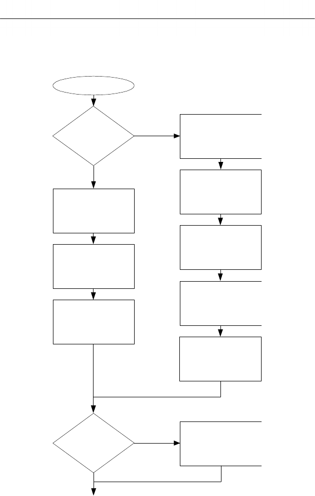
5.2. Flowchart
Start
Connecting
USB cable and
power supply to base
(page 31 / page 32)
Connecting probe to
Saveris base
(page 36)
Use
router? Integrating router
(page 49)
Base with
GSM module?
Inserting batteries
in probe
(page 35)
Yes
No
Inserting SIM card
(page 30)
Connecting
USB cable and
power supply to base
(page 31 / page 32)
Connecting probe to
Saveris base
(page 36)
Inserting batteries
in probe
(page 35)
Connecting GSM
antenna
(page 32)
5 First steps
0970 4020 en 01 31
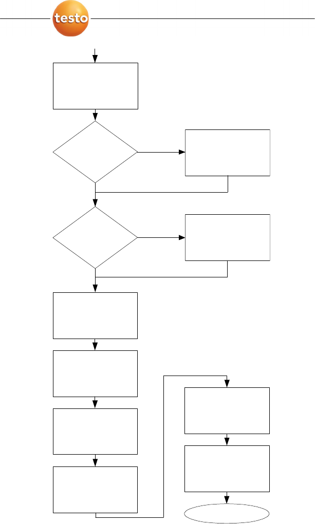
End
Installing
software
(page 38)
Connecting Saveris
base to PC and
starting up hardware
(page 39)
Use
converter?
Yes
No
Integrating Ethernet
probe
(page 57)
Use Ethernet
probes?
Integrating converter
(page 68)
Starting
software
(page 48)
Performing
the test run
(page 69)
Mounting the
hardware
(page 71)
Yes
No
Creating zones
(page 86 )
Configuring the
alarms
(page 87 )
5 First steps
32 0970 4020 en 01 testo AG
Pos: 51 /TD/Erste Sc hritte/testo Saveris/ 00 SIM-Karte einsetzen @ 1\ mod_1197557316734_79. doc @ 6426
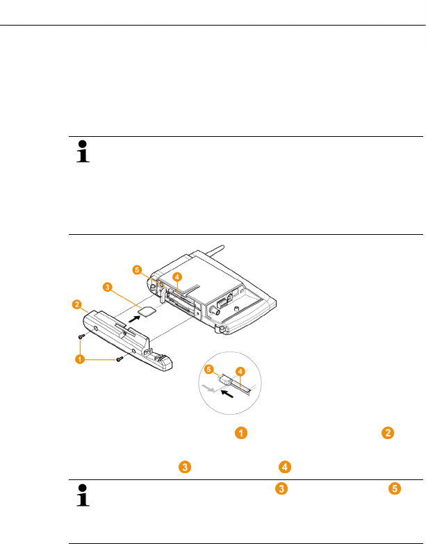
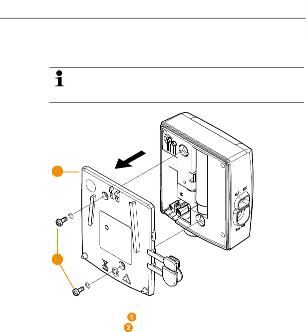
5.3. Inserting SIM card (optional)
With a Saveris base with integrated GSM module, you must
insert the SIM card.
The SIM card for sending SMS messages is not
included in the delivery and must be purchased
separately from a mobile phone provider.
It is recommended that you use a contract card instead
of a so-called prepaid card, as no alarm messages can
be sent if you use up your credit.
1. Loosen screw connection and remove base plate from
the Saveris base.
2. Insert SIM card in the card slot as shown.
When inserting, the SIM card pushes the catch to
the side. If the card is inserted, a spring pushes the
catch back and the SIM card is thus secured in the card
slot.
3. Place the base plate on the base and screw it down.
5 First steps
0970 4020 en 01 33
Pos: 52 /TD/Erste Sc hritte/testo Saveris/ 01 USB-Kabel an Base anschli eßen @ 0\mod_119021019 6906_79.doc @ 4930
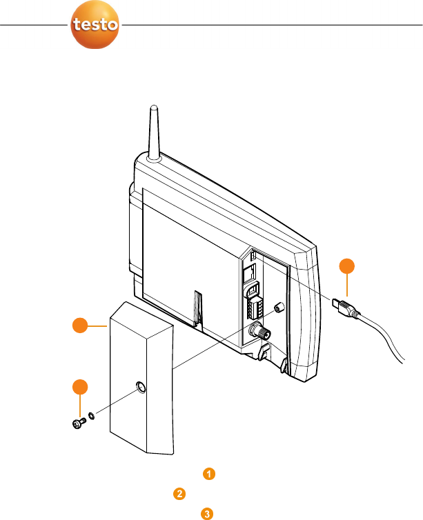
5.4. Connecting USB cable to the Saveris base
1. Loosen and remove screw connection.
2. Remove cover from Saveris Base.
3. Plug the USB cable into the Saveris base.
3
2
1
5 First steps
34 0970 4020 en 01 testo AG
Pos: 53 /TD/Erste Sc hritte/testo Saveris/ 01 Antenne anschließen @ 1\mod_1197628729203 _79.doc @ 6463
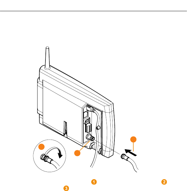
5.5. Connecting GSM antenna (optional)
Pos: 54 /TD/Erste Sc hritte/testo Saveris/ 01b SBE Antenne anschli eßen @ 1\mod_120212369763 9_79.doc @ 8045
Pos: 55 /TD/Erste Sc hritte/testo Saveris/ 01c Antenne anschließen @ 1\ mod_120212374209 3_79.doc @ 8056
> Place antenna cable on the coaxial connection and
screw on .
Pos: 56 /TD/Erste Sc hritte/testo Saveris/ 02 Base mit Stromversor gung verbinden @ 0\mod_1188 477940515_79.doc @ 2955
3
2
1
5 First steps
0970 4020 en 01 35
5.6. Connecting Saveris base with power
supply
You can connect the Saveris base to the power supply via the
included mains unit or via the 24 V AC/DC plug-in/screw
terminal.
Pos: 57 /TD/Erste Sc hritte/testo Saveris/ 02a-1 Stromversorgung üb er Netzteil verbi nden @ 0\mod_119132832684 3_79.doc @ 5392
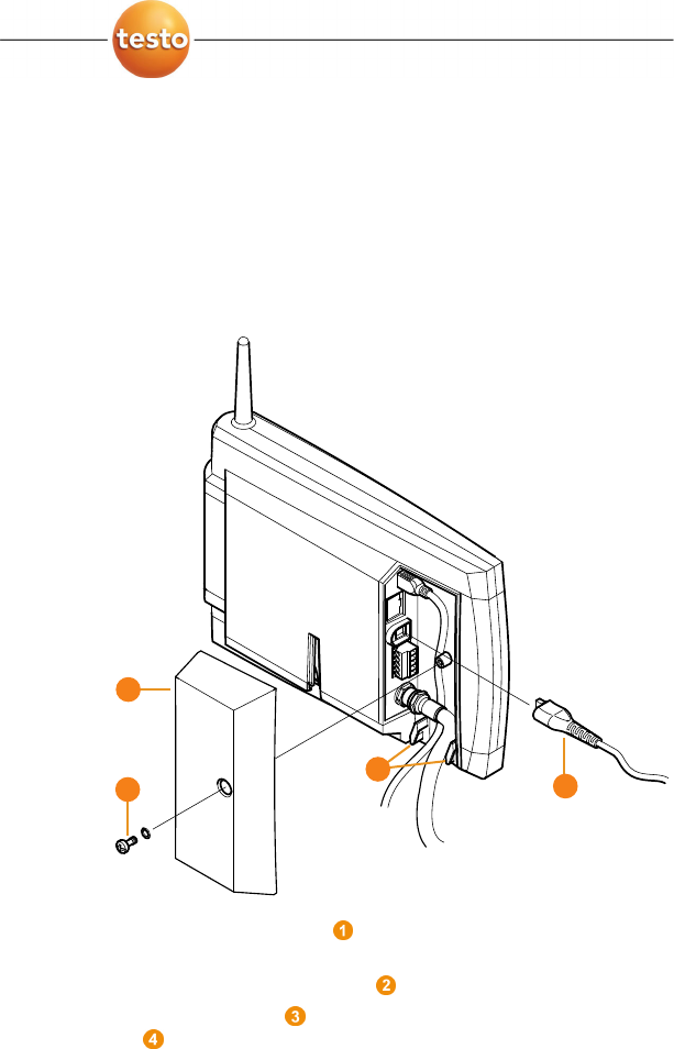
5.6.1. Power supply via mains unit
Pos: 58 /TD/Erste Schri tte/testo Saveris/02a-2 SBE Stro mversorgung über Netztei l verbinden @ 1\mod_12000 57993442_79.doc @ 7524
Pos: 59 /TD/Erste Sc hritte/testo Saveris/ 02a-3 Stromversorgung üb er Netzteil verbi nden @ 1\mod_120005804603 1_79.doc @ 7546
1. Connect mains cable to the Saveris base.
2. Ensure that cabling cannot be pulled out using a cable tie at
the eyelets for strain relief .
3. Place the cover on the Saveris base and screw it down
.
4. Connect mains plug to the power supply.
- The Saveris base automatically switches on after selecting
the language at the base and is ready for operation.
3
4
2
1
5 First steps
36 0970 4020 en 01 testo AG
Pos: 60 /TD/Erste Sc hritte/testo Saveris/ 02b-1 Stromversorgung üb er AC/DC verbinden @ 0\ mod_1191328406187_79. doc @ 5402
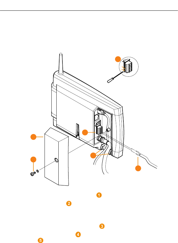
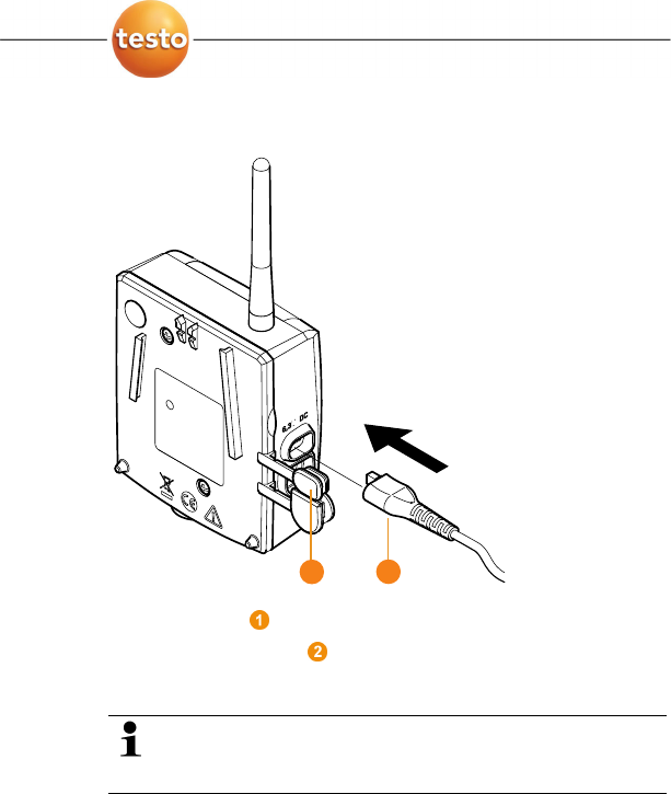
5.6.2. Power supply via plug-in/screw connection
(optional)
Pos: 61 /TD/Erste Schri tte/testo Saveris/02b-2 SBE Stro mversorgung über AC/DC verbinden @ 1\mod_12021243896 13_79.doc @ 8067
Pos: 62 /TD/Erste Sc hritte/testo Saveris/ 02b-3 Stromversorgung üb er AC/DC verbinden @ 1\ mod_1202124473316_79. doc @ 8089
1. Loosen clamping screws no. 1 and no. 2.
2. Insert cable in the terminals as shown.
3. Tighten clamping screws.
4. Ensure that cabling cannot be pulled out using a cable tie at
the eyelets for strain relief .
5. Place the cover on the Saveris base and screw it down
.
- The Saveris base automatically switches on after selecting
the language at the base and is ready for operation.
1
2
2
1
3
4
5
1
5 First steps
0970 4020 en 01 37
Pos: 63 /TD/Erste Sc hritte/testo Saveris/ 02 b Batterien am Fühler ei nlegen @ 0\mod_11913221 24515_79.doc @ 5263
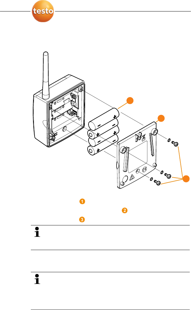
5.7. Inserting batteries in the probes
1. Loosen screws on the rear of the probe.
2. Remove housing cover of probe .
3. Insert batteries .
Ensure that you insert the batteries correctly.
The correct polarity is illustrated in the respective
battery compartment.
4. Place housing cover on probe housing.
5. Screw cover down close to the housing.
A control switch is located in the housing that is
actuated through the cover. To do so, the cover must be
screwed to the probe housing without a gap.
If the cover is not screwed on without a gap, the probe
cannot be operated.
1
2
3
5 First steps
38 0970 4020 en 01 testo AG
Pos: 64 /TD/Erste Sc hritte/testo Saveris/ 03 Fühler an der Base anmeld en @ 0\mod_1188478029328 _79.doc @ 2964
Integrating Saveri s router (optional) Page 52
5.8. Connecting radio probe
You can connect a maximum of 15 probes to the
Saveris base directly via radio.
In addition, you can operate 15 more probes at the
Saveris Base per converter and 5 per router.
Note that a maximum of 254 channels can be
processed by the Saveris software.
1. Change to the Info System menu at the Saveris base with
the [▼] button.
2. Press [Enter] to call up the Login function.
- The status bar in the display shows that the Saveris base
is ready for probe detection.
5 First steps
0970 4020 en 01 39
3. Hold down the connect key on the rear of the probe until
the LED at the probe begins to flash orange.
- The LED at the probe briefly turns green if this was
detected by the Saveris base.
The LED at the Saveris base briefly flashes green and a
prompt appears in the display of the base for the connection
of more probes or routers.
Multiple probes cannot be connected at the Saveris
base simultaneously. Multiple probes can only be
connected one after the other.
4. At the Saveris base, press the
• [Esc] key if no more components are to be connected.
- A note on the required performance of the startup
assistant is shown on the display for about ten seconds.
Then the Saveris base changes to the Info System
menu in which the number of connected components
is now shown.
• Press
[Enter] if further components are to be connected;
see previous step.
5 First steps
40 0970 4020 en 01 testo AG
5. Position the probes precisely at their measurement points to
check the radio link.
6. Briefly press the connect key on the rear of the probe.
If the LED at the probe flashes
• green, a radio link exists.
• red, no radio link exists.
If no radio link to the Saveris base exists even after a
change of location of the probe, connect a router to the
Saveris base; see Integrating Saveris router (optional),
page 52.
Pos: 65 /TD/Erste Sc hritte/testo Saveri s/05a Saveris-Sof tware installieren @ 0\ mod_1188478151968_79. doc @ 2991
5.9. Installing Saveris software
Administrator rights are required to install programs and
drivers under Windows® 2000 SP4, XP and Vista.
1. Insert CD with Saveris software in the CD-ROM drive.
If the installation program does not start automatically, open
Windows Explorer and start the Setup.exe file on the product
CD.
During the installation of the Saveris software the
licence-free database system Microsoft SQL Server
2005 Express is installed – if this is not already present.
The database is protected by the so-called "sa
password", the password for the database
administrator, to prevent unintended changes to the
database.
If a software exists on the computer used that uses the
SQL Server 2005 Express and a password was already
set when this was installed, you then require this sa
password to be able to perform the installation of the
Saveris software.
2. Follow the directions of the installation wizard.
The USB driver for the connection of the Saveris base
is installed with the Saveris software.
If the Saveris base is not recognized as new hardware
when connected to the computer, the USB driver must
be manually installed.
5 First steps
0970 4020 en 01 41
Pos: 66 /TD/Erste Sc hritte/testo Saveris/ 04 Hardware inbetriebn ehmen @ 0\mod_11884781 13640_79.doc @ 2982
5.10. Starting up hardware
The following preconditions must be fulfilled for the startup of
the hardware:
• the Saveris base is ready for operation,
• all probes are connected to the Saveris base and
• the Saveris software is installed on the computer.
1. Connect the Saveris base to the computer via the USB
cable.
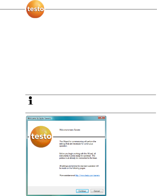
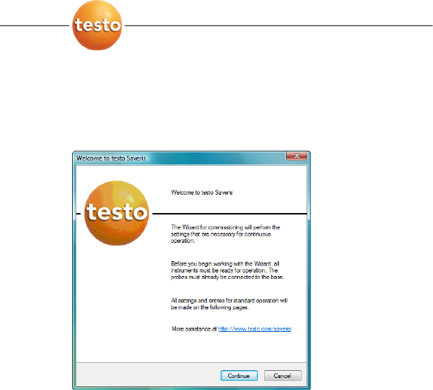
- The startup assistant starts.
Under Windows 2000, you must manually call up the
assistant using Start | All Programs | Testo | Startup
Assistant.
2. Click on [Continue >].
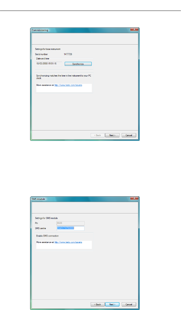
- The general system settings of the Saveris base are shown.
5 First steps
42 0970 4020 en 01 testo AG
3. Click on [Synchronize] to apply the date and time from the
operating system of the computer to the Saveris base.
4. Click on [Continue >].
- If the Saveris base is equipped with a GSM module the
dialogue for entering the basic settings for the SMS service
is shown.
If there is no GSM module continue with step 7.
5 First steps
0970 4020 en 01 43
5. Enter the PIN and the number of the SMS centre in the
fields of the same name.
You can find the PIN and the number of the SMS centre
in the documents for your SIM card.
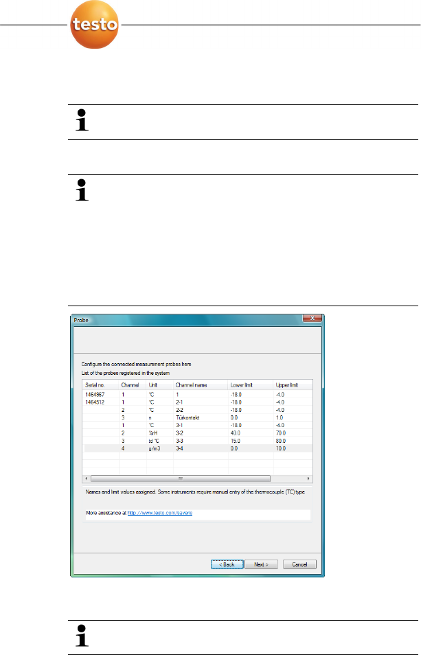
- The list of the probes registered in the Saveris base is
shown.
The fields of the Channel name column for probe
designations are required fields. You must fill in these
fields to be able to continue with the startup.
The Lower limit and Upper limit fields are already
preassigned limit values, but you can adapt the limit
values to your requirements.
The limit values determine as of which reading the
Saveris base triggers an alarm.
6. Click in the Channel name field and enter the designation
of the probe, e.g. "Room 1".
Assign channel names that are not longer than 15
characters.
5 First steps
44 0970 4020 en 01 testo AG
> Click in the Lower limit field and change the lower limit
value.
If all probes are to have the same limit value, click on
the column title with the right mouse button and then
click on Apply to all in the context menu. This also
applies for the upper limit value in the next step.
> Click in the Upper limit field and change the upper limit
value.
> Click in the TC type field and enter the type of thermocouple
(Enter: J, K, S or T) if this information is required for the
instrument.
> Perform step 5 and the following for all other probes until all
required fields are filled.
7. Click on [Continue >].
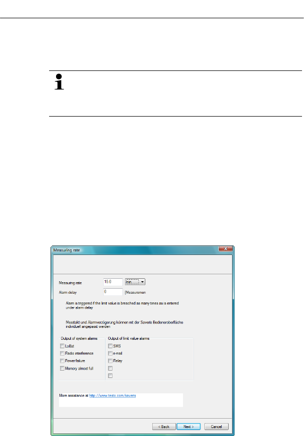
- The settings for measuring cycle, the alarm delay and the
alarm issue are shown.
5 First steps
0970 4020 en 01 45
8. Enter Measuring cycle and determine its Unit.
The measuring cycle determines in which intervals a
new reading is saved in the Saveris base.
Possible settings for the unit:
• sec (second)
• min (minute)
• h (hour).
The smallest transfer rate for radio probes is one
minute.
Later the settings can be changed for every probe
separately in the software.
9. Determine Alarm delay.
If you enter the value "5" for example, an alarm is not
triggered by the Saveris base until the fifth time that the
limit value is exceeded.
Later the settings can be changed for every probe
separately in the software.
10. Determine the issue options for the limit value alarms.
Possible options:
• SMS (optional with Saveris base with GSM module)
• E-mail
• Relay of the Saveris base.
The system alarms are above all used for pointing out
irregularities in the measurement system. If no reaction
follows the system alarms, uninterrupted data recording
is not guaranteed.
If a system alarm is issued via SMS or E-mail time
delays may occur.
The notification function via SMS is only available if the
Saveris base is equipped with a GSM module.
Later the settings can be changed for every probe
separately in the software.
5 First steps
46 0970 4020 en 01 testo AG
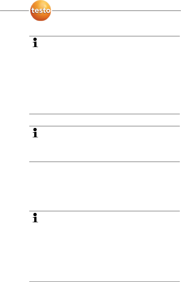
11. Click on [Continue >].
- If a router is connected at the Saveris base the configuration
of the connection type for the probes is shown.
If no router is connected continue with step 15.
12. Click in the Connection type cell of the probe which is to be
assigned to a router.
- The cell is shown as a selection list.
13. Open the selection list via the button and select the router
to which the probe is to be assigned.
14. Perform steps 12 and 13 for all remaining probes whose
measurement data is to be transmitted to the Saveris base
via a router.
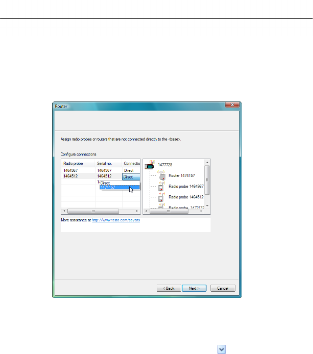
15. Click on [Continue >].
- If the Saveris base is equipped with a GSM module, the
settings for the SMS alarms are shown.
If there is no GSM module continue with step 28.
5 First steps
0970 4020 en 01 47
16. Enter the Telephone number of the recipient of the alarm
messages.
Enter with country code, network or area code and local
number.
17. Activate Forward checkbox if the alarm message should be
sent to a second recipient if recipient 1 does not respond.
- The
min list field and the 2nd telephone number input field
are shown.
18. Use the min list field to determine after what time span the
alarm message should be forwarded if recipient 1 does not
respond.
19. Enter the telephone number to which the alarm message
should be forwarded in the 2nd telephone number field.
Enter with country code, network or area code and local
number.
20. Enter a text in the Message field that should be attached to
the alarm message.
You can send a test report via the button of the same
name to check whether all settings are correct.
5 First steps
48 0970 4020 en 01 testo AG
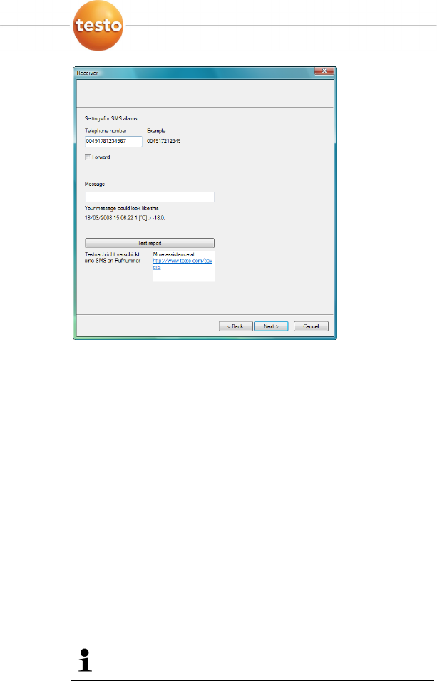
21. Click on [Continue >].
- The settings for the reporting are shown.
These specifications are applied as the default setting
for the reporting. You can change these settings or
create new configurations for the reports at any time;
see chapter "Report settings".
22. Deactivate Automatically create reports checkbox if this
function should not be used.
- In this case, continue with step 20.
23. Determine the intervals in which the reports should be
automatically created.
24. Determine which content the reports should include.
> Activate Send to receiver checkbox if reports should be
sent by e-mail.
- The input fields for the e-mail address and the subject line
as well as the [Address book] button are shown.
> Enter the e-mail address of the recipient in the input field or
select the recipient from the Outlook contacts using the
[Address book].
> Enter text for the subject line of the e-mail.
25. Enter the address under Cover sheet address field that
should be displayed on the top of the report.
5 First steps
0970 4020 en 01 49
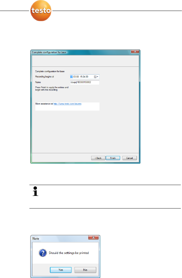
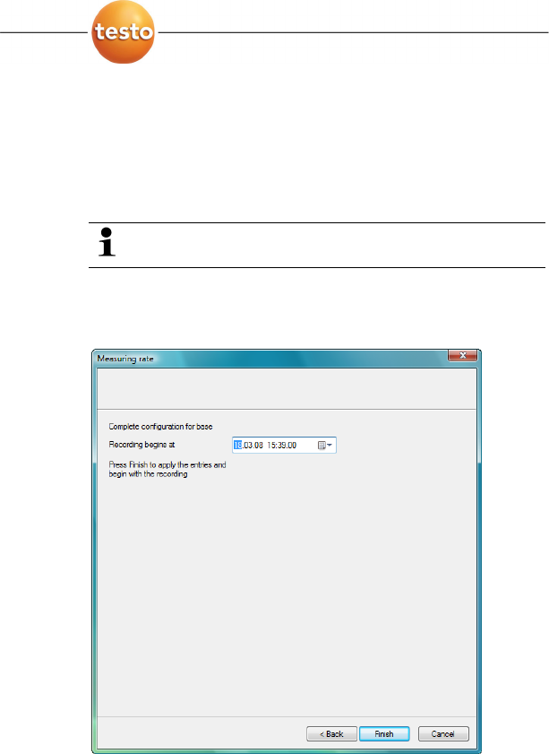
26. Click on [Continue >].
- The wizard is shown with the information on the start of
measurement and the list of the registered probes.
27. Postpone the start of measurement, if necessary.
> Change the project name in the Name field.
Consider a clear-cut name for the project that you will
be able to easily associate later.
The project name cannot subsequently be changed.
28. Click on [Finish] to complete the startup of the hardware.
- A dialogue for displaying and printing the configuration
settings is shown.
5 First steps
50 0970 4020 en 01 testo AG
29. Click on
• [Yes] if the settings should be shown in the Internet
browser and printed from there.
• [No] if the settings should not be shown.
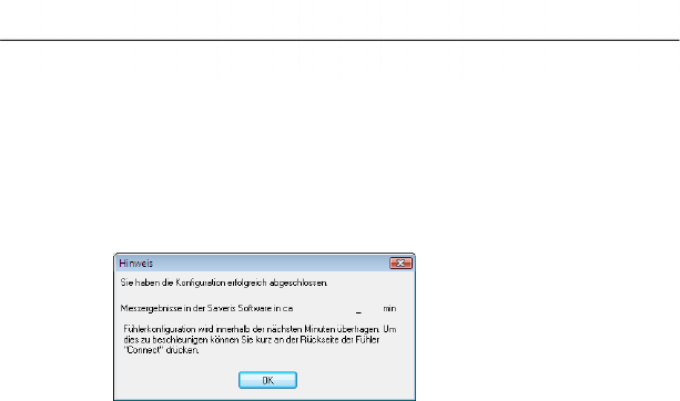
The dialogue for the conclusion of the startup is shown.
30. Consecutively press the connect button on all probes to
synchronize the probes.
31. Close the dialogue with [OK].
- The hardware is now ready for operation.
Pos: 67 /TD/Produkt verwenden/testo Saver is/01 Start/01_Saver is-Software star ten @ 0\mod_1189076832593 _79.doc @ 3933
5 First steps
0970 4020 en 01 51
5.11. Starting Saveris software
Ensure that the Saveris software is not already open,
for example in multi-user operation under Windows®
Vista.
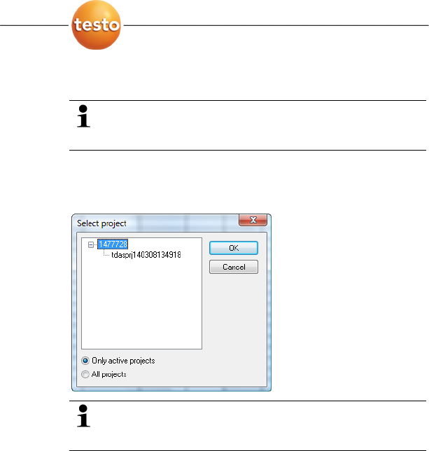
1. Select [Start] | All Programs | Testo | Saveris.
- The
Testo Saveris software program window is opened
with the Select project dialogue.
If the software will not start, check whether the testo
tdassvcs service is started in the service management
of the operating system and restart it, if needed.
2. Select the
• Only active projects option if the data from a running
project should be opened
• All projects option if the data from a completed project
should be opened.
3. Select the project that is to be opened in the tree structure.
4. Confirm with [OK].
- The
Testo Saveris software program window is shown with
the selected data record in the foreground.
Pos: 68 /TD/Erste Sc hritte/testo Saveris/ Hardware erweitern/ Messsystem erweiter n @ 1\mod_1197551581796 _79.doc @ 6327
5 First steps
52 0970 4020 en 01 testo AG
5.12. Expand measuring system
In this chapter, you learn how to integrate the Saveris router,
converter and Ethernet probes into the measuring system.
Pos: 69 /TD/Erste Sc hritte/testo Saveris/ Hardware erweitern/ 01 Router einbinden/0 0 Router einsetzen @ 1\mod_119 7549116203_79.doc @ 6304
5.12.1. Integrating Saveris router (optional)
You can use a Saveris router to optimize the radio
communication with poor structural conditions or to extend the
transmission path. The router receives the signals of the radio
probes and forwards them to the Saveris base.
The measurement data of up to five radio probes can
be transmitted per router to the Saveris base.
Multiple routers can be integrated in the measuring
system but cannot be connected in series to cover
extremely long transmission paths. In this case, a
converter should be used; see "Integrating Saveris
converter (optional)".
The integration of a router is performed in three steps:
1. Connect router to the power supply.
2. Connect router to the Saveris base.
3. Assign radio probes to the router.
When positioning a router please note the following
points:
• When integrating several probes via a router, the
probe with the weakest radio link determines the
position of the router.
Mount the router in such a way that this probe has
an ideal radio link.
• Probes and router should be mounted so that the
antennas are aligned upwards.
• The radio link between probes and the router as well
as the router and the Saveris base should not be
strongly influenced by structural conditions (walls,
shelves etc.).
Mount the router and probe so that "visual contact"
exists with as many radio links as possible.
5 First steps
0970 4020 en 01 53
Pos: 70 /TD/Erste Sc hritte/testo Saveris/ Hardware erweitern/ 01 Router einbinden/0 1 Router-Strom @ 1\mod_1 197548324640_79.doc @ 6294
5.12.1.1. Connecting router with power supply (mains unit)
1. Open cover .
2. Insert mains cable .
3. Insert mains plug into a socket.
The wall mounting of a router is performed in the same
ways as for a probe; see "Mounting the probe on the
wall".
12
5 First steps
54 0970 4020 en 01 testo AG
Pos: 71 /TD/Erste Sc hritte/testo Saveris/ Hardware erweitern/ 01 Router einbinden/0 1b Router-ACDC @ 1\mod_119797827 3593_79.doc @ 6543
5.12.1.2. Connecting router with power supply (AC/DC)
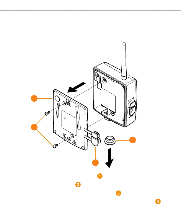
1 Remove protection caps .
2. Loosen screws on the rear of the router.
3. Remove housing cover of router .
4. Unscrew and remove cover cap of cable opening .
1
2
3
4
5 First steps
0970 4020 en 01 55
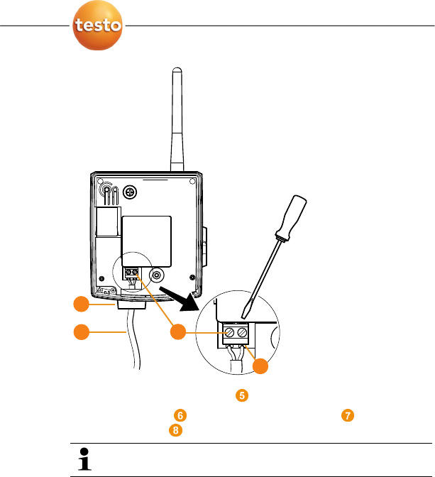
5. Loosen clamping screws .
6. Route cabling through the cable opening and insert in
the terminals .
It is not necessary to note the polarity.
7. Tighten clamping screws.
7
5
6
8
5 First steps
56 0970 4020 en 01 testo AG
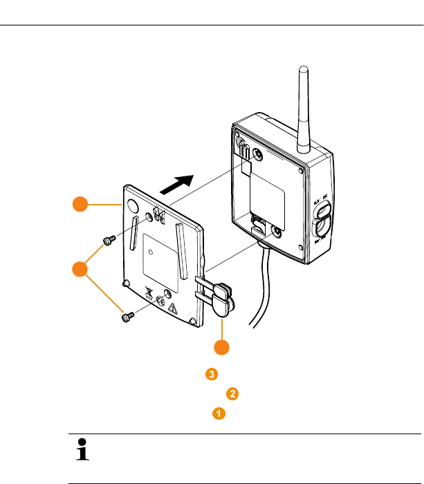
8. Place housing cover on the router.
9. Screw on housing cover .
10. Insert protection caps .
The wall mounting of a router is performed in the same
ways as for a probe; see "Mounting the probe on the
wall".
Pos: 72 /TD/Erste Sc hritte/testo Saveris/ Hardware erweitern/ 01 Router einbinden/0 2 Router anmelden @ 1\mod_11 97548238578_79.doc @ 6274
2
1
3
5 First steps
0970 4020 en 01 57
5.12.1.3. Connecting router
You can connect a maximum of 15 routers to the
Saveris base.
Also note that connecting multiple routers in series is
not possible.
1. Change to the Info System menu at the Saveris base with
the [▼] button.
2. Press [Enter] to call up the Login function.
- The status bar in the display shows that the Saveris base
is ready for router detection.
5 First steps
58 0970 4020 en 01 testo AG
3. Hold down the connect key on the rear of the router until
the LED at the router begins to flash orange.
- The LED at the router briefly turns green if this was
detected by the Saveris base.
The LED at the Saveris base briefly flashes green and a
prompt appears in the display of the base for the connection
of more probes or routers.
Multiple routers cannot be connected at the Saveris
base simultaneously. Multiple routers can only be
connected one after the other.
4. At the Saveris base, press the
• [Esc] key if no more components are to be connected.
- A note on the required performance of the startup
assistant is shown on the display for about ten seconds.
Then the Saveris base changes to the Info System
menu in which the number of connected components
is now shown.
• Press [Enter] if further components are to be connected;
see previous step.
Pos: 73 /TD/Erste Sc hritte/testo Saveris/ Hardware erweitern/ 01 Router einbinden/0 3 Fühler zuweisen @ 1\mod_1197 548250906_79.doc @ 6284
5.12.1.4. Assigning probes
To assign a probe to a router, both must be connected
in the Saveris base.
5 First steps
0970 4020 en 01 59
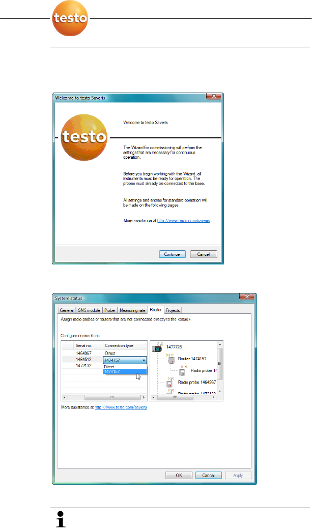
1. Under Start | All Programs | Testo click on Saveris
Startup Assistant.
- The welcome dialogue of the startup assistant is shown.
2. Click on [Continue >].
- The
System status dialogue with the General tab is shown.
3. Change to Router tab.
The Direct connection type means that the probe is
connected directly in the Saveris base or a converter.

5 First steps
60 0970 4020 en 01 testo AG
4. Click in the Connection type cell of the probe which is to be
assigned to a router.
- The cell is shown as a selection list.
5. Open the selection list via the button and select the router
to which the probe is to be assigned.
6. Position the probe within the radio range of the base and
briefly push the connect button on the rear of the probe
once.
> Perform steps 4 to 6 for all remaining probes whose
measurement data is to be transmitted to the Saveris base
via a router.
7. Position the probes and router at their mounting locations to
check the radio links.
8. Briefly press the connect key on the rear of the probe.
If the LED on the front of the probe flashes
• green, a radio link to the router exists.
• red, no radio link to the router exists.
5 First steps
0970 4020 en 01 61
9. Briefly press the connect key on the rear of the router.
If the LED on the front of the router flashes
• green, a radio link to the Saveris base exists.
• red, no radio link to the Saveris base exists.
If no radio link exists after changing the location of the
probe and/or router, introduce a converter; see
"Integrating Saveris converter (optional)".
Pos: 74 /TD/Erste Sc hritte/testo Saveris/ Hardware erweitern/ 03 Ethernet-Fühler einbi nden/00 Ethernet- Fühler einsetzen @ 1\mod_1 197552336953_79.doc @ 6336
5.12.2. Integrating Saveris Ethernet probe (optional)
In addition to the Saveris radio probes, you can use probes that
are connected to the Ethernet interface of the Saveris base.
This also enables the data transfer from the probe to the base
over long stretches if you do not wish to use a router or
converter.
You must enter the IP address of the Saveris base in
the Ethernet probe using the separate parameterization
software.
If your computer has the Dynamic Host Configuration
Protocol (DHCP), its IP address is automatically
assigned to the Ethernet probe. If this is not the case,
you must automatically assign the IP address to the
probe.
This chapter contains all required information for this.
You can connect several Ethernet probes to the Saveris
base using a so-called switch. In this context, note that
a maximum of 150 probes can be connected or 254
measurement channels recorded at the Saveris base.
Pos: 75 /TD/Erste Sc hritte/testo Saveris/ Hardware erweitern/ 03 Ethernet-Fühler einbi nden/01 Netzwerkkabe l @ 1\mod_120342143300 0_79.doc @ 8193
5 First steps
62 0970 4020 en 01 testo AG
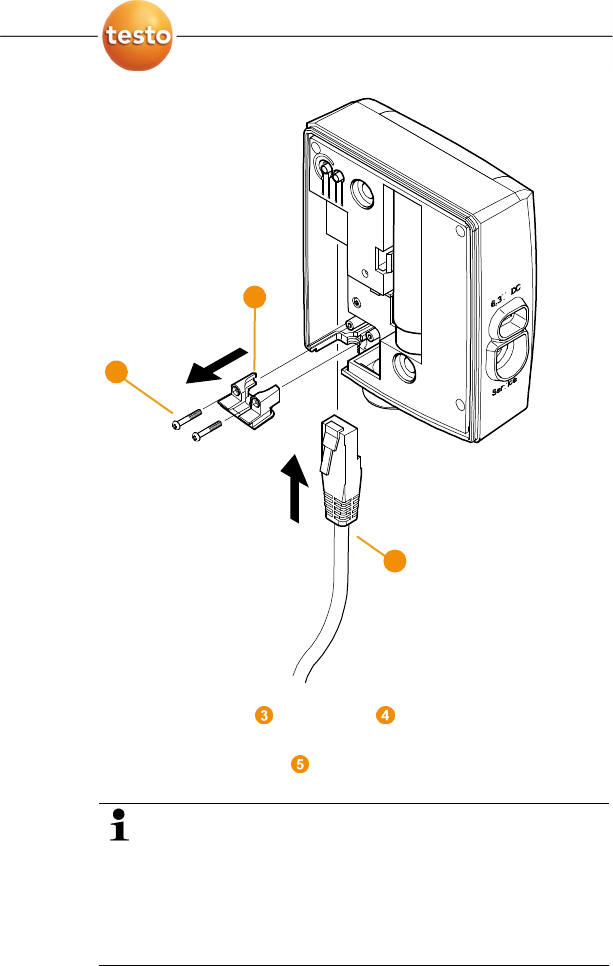
5.12.2.1. Connecting the network cable.
Use a network cable with a diameter between 5.8 mm
and 6.8 mm to ensure the leaktightness of the probe
housing.
1. Loosen screws on the rear of the probe and remove the
housing cover .
1
2
5 First steps
0970 4020 en 01 63
2. Loosen screws at the panel for the network cable and
remove panel.
3. Slide network cable with the tongue pointing up into the
Ethernet jack until it engages.
If you wish to connect the Saveris Ethernet probe to the
power supply via the 24 V AC/DC plug-in/screw terminal
and not via the mains adapter, do not screw on the
housing cover until after connecting the power supply.
The connection for the power supply via plug-in/screw
terminal is performed as with the Saveris router; see
Connecting router with power supply (AC/DC), page 54.
4
3
5
5 First steps
64 0970 4020 en 01 testo AG
4. Place the housing cover on the probe and screw it down.
You can connect the probe to the network via a network
hub or directly at the Saveris base via the Ethernet jack.
Pos: 76 /TD/Erste Sc hritte/testo Saveris/ Hardware erweitern/ 03 Ethernet-Fühler einbi nden/01c Stromversor gung @ 1\mod_1203423 817781_79.doc @ 8270
5.12.2.2. Connecting Ethernet probe with power supply (mains unit)
The connection for the power supply via 24 V AC/DC
plug-in/screw terminal is performed as with the Saveris
router; see Connecting router with power supply
(AC/DC), page 54.
1. Open the cover for the power supply.
2. Insert mains cable .
3. Insert mains plug into a socket.
1
2
5 First steps
0970 4020 en 01 65
Pos: 77 /TD/Erste Sc hritte/testo Saveris/ Hardware erweitern/ 03 Ethernet-Fühler einbi nden/01b USB-Kabel @ 1\ mod_1203423817203_79. doc @ 8259
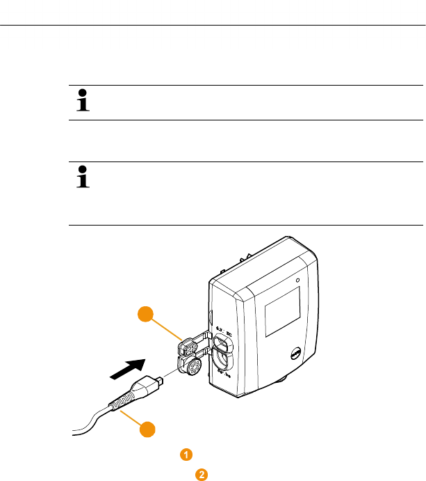
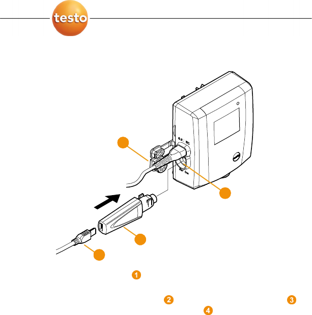
5.12.2.3. Connecting USB cable and installing driver
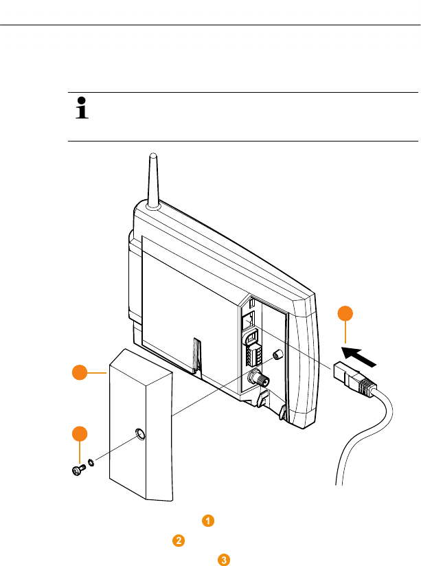
1. Open the cover of the service interface at the Ethernet
probe.
2. Connect the USB cable with the testo USB adapter
and insert in the service interface .
3. Insert product CD with the testo Saveris software in the CD-
ROM drive of the computer.
4. Connect the USB cable to the computer.
- The wizard for the installation of the driver is started.
5. Follow the directions of the installation wizard.
Pos: 78 /TD/Erste Sc hritte/testo Saveris/ Hardware erweitern/ 03 Ethernet-Fühler einbi nden/02 Software i nstallieren @ 1\mod_120 3421488750_79.doc @ 8215
1
2
4
3
5 First steps
66 0970 4020 en 01 testo AG
5.12.2.4. Installing parameterization software
Administrator rights are required to install programs and
drivers under Windows® 2000 SP4, XP and Vista.
1. Insert CD with Saveris software in the CD-ROM drive.
> If applicable, cancel the installation program the starts up
automatically.
2 Open Windows Explorer and mark the entry of the CD-ROM
drive in which the Saveris product CD is located.
3. Open the dbv4ethernet folder and start the Setup.exe file.
4. Follow the directions of the installation wizard.
- The software is ready to be used after restarting the
computer.
Pos: 79 /TD/Erste Sc hritte/testo Saveris/ Hardware erweitern/ 03 Ethernet-Fühler einbi nden/03 Verbindu ngsdaten zuweisen @ 1\mod_ 1203421515781_79.d oc @ 8226
5.12.2.5. Assigning connection data
You must now enter the connection settings for the Ethernet
probes.
1. Open the assistant for entering the connection settings via
Start | All Programs | Testo | Ethernet device startup.
- The assistant is started with the welcome dialogue.
5 First steps
0970 4020 en 01 67
2. Click on [Continue >].
- The dialogue
• Address of the Saveris base is shown if the computer
has DHCP.
In this case, continue with step 4.
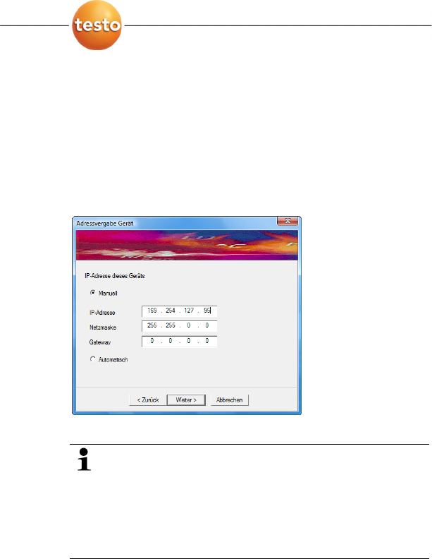
• Instrument address allocation is shown if an automatic
allocation of the IP address via DHCP is not possible.
You must manually enter the connection data.
3. Enter IP address, Netmask and Gateway.
The first two blocks of the IP address must match those
from the Saveris base. The last two blocks can be
selected freely. However, the IP address may not yet be
assigned.
The IP address, the netmask and the gateway can be
read off at the Saveris base in the Info Base menu;
also see chapter Displays, page 16.
4. Click on [Continue >].
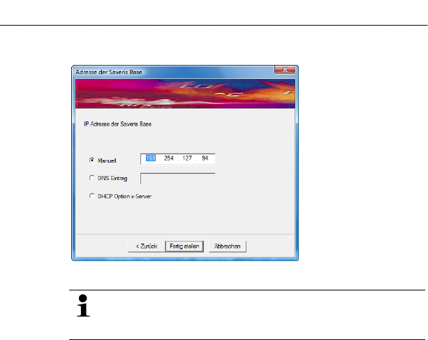
- The dialogue for the entry of the connection data for the
base is shown.
5 First steps
68 0970 4020 en 01 testo AG
5. Enter IP address of the Saveris base.
The IP address can be read off at the Saveris base in
the Info Base menu; also see chapter Displays, page
16.
6. Click on [Finish].
- The Ethernet probe is restarted, synchronized with the
Saveris base and the number of connected Ethernet probes
in the display of the base is increased by 1; see

5 First steps
0970 4020 en 01 69
Displays, page 16.
Pos: 80 /TD/Erste Sc hritte/testo Saveris/ Hardware erweitern/ 03 Ethernet-Fühler einbi nden/04 Netzwerkk abel an Base anschließen @ 1\ mod_1203430798656_79. doc @ 8313
5 First steps
70 0970 4020 en 01 testo AG
5.12.2.6. Connecting the network cable to the Saveris base
You can integrate the Saveris base into a network via a
network hub or connect the Ethernet probe directly via a
network cable.
1. Loosen and remove screw connection.
2. Remove cover from Saveris Base.
3. Plug the network cable into the Saveris base.
Pos: 81 /TD/Erste Sc hritte/testo Saveris/ Hardware erweitern/ 03 Ethernet-Fühler einbi nden/05 Ethernet- Fühler inbetrieb nehm en @ 1\mod_1203421551984_7 9.doc @ 8237
3
2
1
5 First steps
0970 4020 en 01 71
5.12.2.7. Starting up Ethernet probes
1. Open the assistant for starting up new hardware component
via Start | All Programs | Testo | Startup Assistant.
- The assistant is opened with the welcome screen.
2. Click on [Continue >].
- The
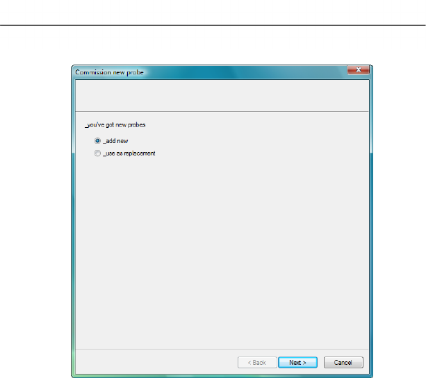
Commission new probe dialogue is shown.
5 First steps
72 0970 4020 en 01 testo AG
3. Leave default setting and click on [Continue >].
- The list of the probes newly registered in the Saveris base is
shown.
5 First steps
0970 4020 en 01 73
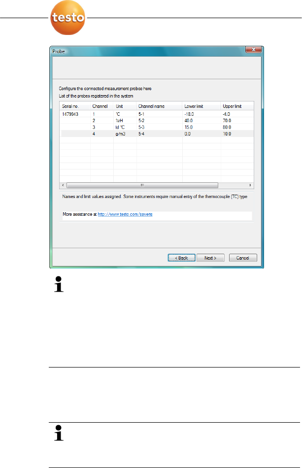
The fields of the Channel name column for probe
designations are required fields. You must fill in these
fields to be able to continue with the startup.
The Lower limit and Upper limit fields are already
preassigned limit values, but you can adapt the limit
values to your requirements.
The limit values determine as of which reading the
Saveris base triggers an alarm.
4. Click in the Channel name field and enter the designation
of the probe, e.g. "Room 4".
> Click in the Lower limit field and change the lower limit
value.
If all probes are to have the same limit value, click on
the column title with the right mouse button and then
click on Apply to all in the context menu. This also
applies for the upper limit value in the next step.
> Click in the Upper limit field and change the upper limit
value.
> Perform step 4 and the following for all other new probes
until all required fields are filled.
5 First steps
74 0970 4020 en 01 testo AG
5. Click on [Continue >].
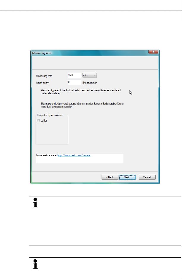
- The settings for measuring cycle, the alarm delay and the
alarm issue are shown.
6. Enter the Measuring cycle and determine its Unit.
The measuring cycle determines in which intervals a
new reading is saved in the Saveris base.
Possible settings for the unit:
• sec (second)
• min (minute)
• h (hour).
7. Determine Alarm delay.
If you enter the value "5" for example, an alarm is not
triggered by the Saveris base until the fifth time that the
limit value is exceeded.
5 First steps
0970 4020 en 01 75
8. Determine the issue options for the limit value alarms.
Possible options:
• SMS (optional with Saveris base with GSM module)
• E-mail
• Relay of the Saveris base.
The notification function via SMS is only available if the
Saveris base is equipped with a GSM module.
9. Click on [Continue >].
- The wizard is shown with the setting for the start of
measurement and the list of the newly registered probes.
10. Postpone the start of measurement, if necessary.
11. Click on [Finish] to complete the startup of the hardware.
- A note on the successful configuration of the hardware is
shown.
12. Press [OK] to confirm the note.
- The new hardware is now ready for operation.
5 First steps
76 0970 4020 en 01 testo AG
Pos: 82 /TD/Erste Sc hritte/testo Saveris/ Hardware erweitern/ 02 Converter einbinden/ 00 Converter einset zen @ 1\mod_1197550607093 _79.doc @ 6315
5.12.3. Integrating Saveris converter (optional)
If the distance between the radio probe or router is too large for
a radio transmission, you can integrate a Saveris converter into
the measuring system. The converter is connected to the
Saveris base by means of an Ethernet cable and converts the
radio signals to Ethernet signals.
The measurement data of up to 15 radio probes can be
transmitted with the converter to the Saveris base.
You can connect several converters to the Saveris base
using a so-called switch. In this context, note that a
maximum of 150 probes can be connected or 254
measurement channels recorded at the Saveris base.
The preparation for the commissioning of a converter is
performed as with a Saveris Ethernet probe; see
Connecting the network cable., page 62 up to and
including Connecting the network cable to the Saveris
base, page 70.
Connecting probe to converter
A probe that you wish to connect to the Saveris
converter may not be registered at the Saveris base. If
this is the case, you must log the probe out of the base
before you can continue with the connection at the
converter; see Deleting components, page 130.
1. Briefly press the connect button on the rear of the converter.
- The LED at the converter lights green and the converter is
ready for probe detection.
2. Press the connect key on the rear of the probe until the LED
at the probe begins to flash orange.
- The LED at the probe briefly turns green if this was detected
by the Saveris converter.
The probe is connected at the converter and this transmits
the measurement data of the probe to the Saveris base.
Pos: 83 /TD/Erste Sc hritte/testo Saveris/ 06 ****Probelauf/ 00 Probelauf und Abnahme durc hführen @ 0\mod_1189157 354187_79.doc @ 4054
5 First steps
0970 4020 en 01 77
5.13. Performing the test run
The test run must be performed to ensure proper
operation of the measuring system.
Pos: 84 /TD/Erste Sc hritte/testo Saveris/ 06 ****Probelauf/ 01 Systemverfügbarkei t prüfen @ 0\mod_118915739 5875_79.doc @ 4094
5.13.1. Checking system availability
Wait for the first connection between the Saveris base
and the probes to check the system availability.
> Click on System in the navigation area.
- The following entries are shown in the tree structure in the
data window:
• Base
• Radio probe
• Ethernet probe
• Router
• Converter.
1. Open the Radio probe entry.
- The active channels of the probes connected in the system
are shown.
2 Click on a channel to open the settings and check the Radio
quality.
> Repeat step 2 for all other probes.
If no values have accumulated for a probe for a while,
check whether a connection exists between the probe
and the Saveris base by briefly pressing the connect
button at the probe. The LED at the probe shows the
connection status; also see "Meaning of the LED
displays at the probes " for this.
Pos: 85 /TD/Erste Sc hritte/testo Saveris/ 06 ****Probelauf/ 02 Alarmkette prüfen @ 0\mo d_1189157374281_79.doc @ 4064
5 First steps
78 0970 4020 en 01 testo AG
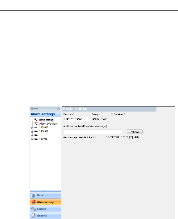
5.13.2. Checking alarm chain
You can trigger an alarm and control the sending of the
messages without having to bring about a real alarm situation.
> Click on Alarms in the navigation area.
- In the data window, the Basic setting and Alarm overview
submenus as well as the probes connected in the Saveris
base are shown.
1. Click on Basic setting.
- The basic setting for the alarms is shown in the display
range.
2. Click on the [Test report] button.
- A test report is sent to the mobile phone number entered.
Pos: 86 /TD/Erste Sc hritte/testo Saveris/ 07 **** Montage der Hardw are/00 Hardware montier en @ 0\mod_1189157579984 _79.doc @ 4124
5 First steps
0970 4020 en 01 79
5.14. Mounting the hardware
The notes in chapter "Ensure safety" must absolutely be
observed when mounting the Saveris components.
Do not mount the Saveris base and the probes at their
locations until the measuring system functions as
expected.
After mounting, perform another test run of the system;
also see "Performing the test run".
Pos: 87 /TD/Erste Sc hritte/testo Saveris/ 07 **** Montage der Hardw are/01 Base an der Wand montier en @ 0\mod_1189157492531 _79.doc @ 4105
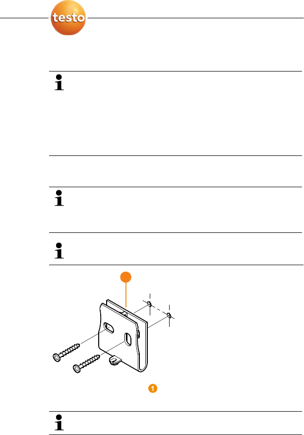
5.14.1. Mounting the Saveris base on the wall
When selecting the location for the Saveris base,
please take into account that this must be positioned
close enough to the computer used and a possible
power supply in accordance with the cabling provided.
The mounting materials (screws, anchor plugs etc.) are
not included in the delivery.
1. Position wall bracket at the desired location.
2. Using a pen, mark the locations for the fastening screws.
The distance between the fastening screws is 25 mm.
3. Prepare the fastening location for the attachment in
accordance with the material (e.g. drill hole, insert anchor
plug).
4. Fasten wall bracket using appropriate screws.
1
5 First steps
80 0970 4020 en 01 testo AG
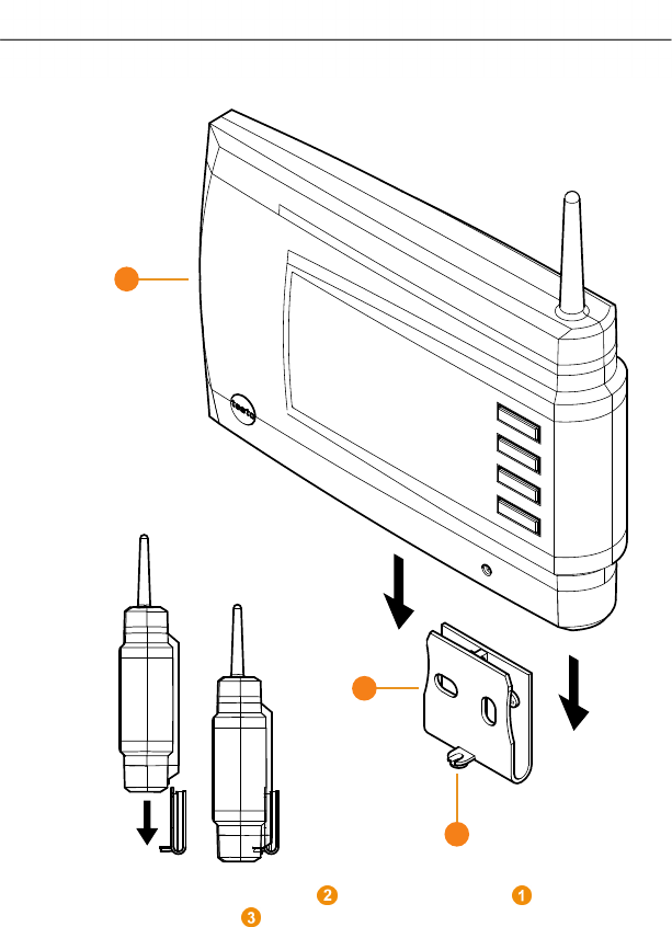
5. Place Saveris base on the wall bracket and secure
with screw .
Pos: 88 /TD/Erste Sc hritte/testo Saveris/ 07 **** Montage der Hardw are/01b Base mit Standfuß @ 0\mo d_1190975629546_79.doc @ 5233
2
1
3
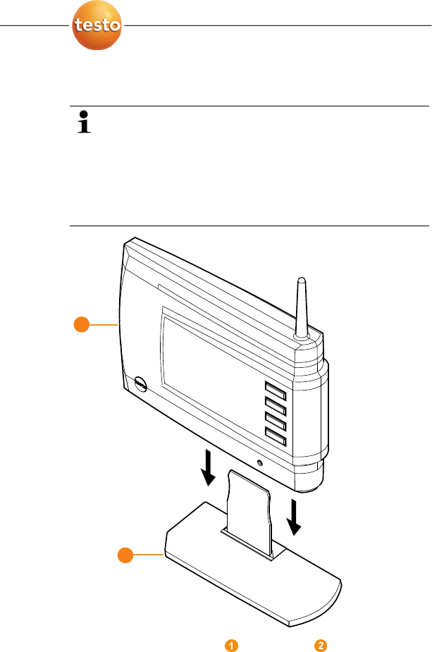
5 First steps
0970 4020 en 01 81
5.14.2. Setting up Saveris base with stand
When selecting the location for the Saveris base, take
into account the following points:
• The Saveris base must stand on a level, non-slip
surface.
• The Saveris base must be positioned close enough
to the computer used and a possible power supply
in accordance with the cabling provided.
1. Place the Saveris base on the stand .
2. Set up the Saveris base at the desired location.
1
2
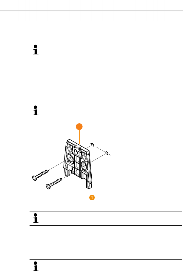
5 First steps
82 0970 4020 en 01 testo AG
Pos: 89 /TD/Erste Sc hritte/testo Saveris/ 07 **** Montage der Hardwar e/03 Fühler montieren @ 0\ mod_1189157541812_79. doc @ 4114
5.14.3. Mounting the probe on the wall
When selecting the location, take into account the
following points:
• The range of the probe may not be exceeded; see
"Connecting radio probe" and "Performing the test
run".
• Attach the probe in such a way that the readings
cannot be distorted, e.g. by exposure to direct
sunlight
The mounting materials (screws, anchor plugs etc.) are
not included in the delivery.
1. Position wall bracket at the desired location.
2. Using a pen, mark the locations for the fastening screws.
The distance between the fastening screws is 30 mm.
3. Prepare the fastening location for the attachment in
accordance with the material (e.g. drill hole, insert anchor
plug).
4. Fasten wall bracket using appropriate screws.
The wall bracket must be screwed down with the
smooth surface facing the wall.
1
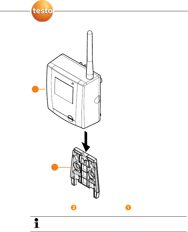
5 First steps
0970 4020 en 01 83
5. Place probe on the wall bracket until it engages.
Please refer to "Removing probe from wall bracket" for
removing the probe from the wall bracket.
Pos: 90 /TD/Erste Sc hritte/testo Saveris/ 07 **** Montage der Hardw are/04 System prüfen @ 0\ mod_1191327191562_79. doc @ 5362
5.14.4. Checking the measuring system again
> Perform another test run at the measuring system; see "
1
2
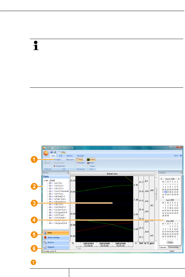
6 Using the product
84 0970 4020 en 01 testo AG
Performing the test run".
After mounting the hardware, perform another check of
the system to test the proper function of the measuring
system.
You can thus recognize whether probes are located
outside of the range of the Saveris base, where
applicable, or the radio link is interfered with by
structural conditions.
Pos: 91 /TD/--- Seitenwechsel --- @ 0\mod_1173774430601_0.doc @ 283
Pos: 92 /TD/Überschr iften/6. Produkt ver wenden @ 0\mod_117377492855 4_79.doc @ 328
6 Using the product
Pos: 93 /TD/Produkt verwenden/testo Saver is/01 Start/02_Bedie noberfläche_01 @ 0\mod_11 89076833359_79.doc @ 3943
6.1. User interface
In this chapter, you learn how the user interface of the Saveris
software is designed.
Pos: 94 /TD/Produkt ver wenden/testo Saveris/ 01 Start/02_Bedienoberf läche_02_SBE @ 1\mod_11979837944 06_79.doc @ 6583
Pos: 95 /TD/Produkt verwenden/testo Saver is/01 Start/02_Bedie noberfläche_03 @ 1\mod_11 97983802515_79.doc @ 6603
Menu bar
Menu Explanation
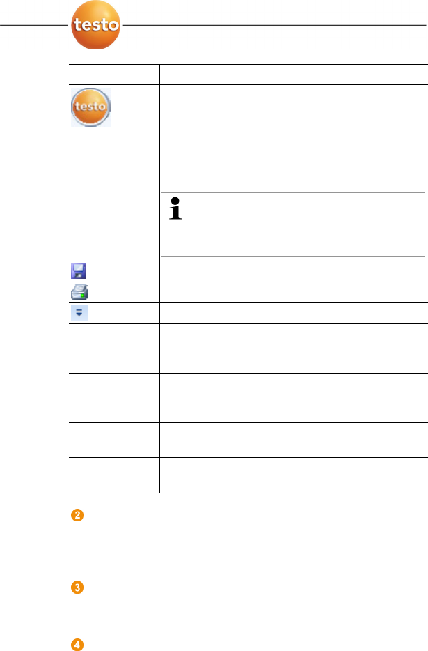
6 Using the product
0970 4020 en 01 85
Menu Explanation
All functions that you require to open, close,
save, delete and print.
The recently used files are also available as a
list for opening.
Using this menu, the program can also be
ended.
With the Send command, you can send
measurement results by e-mail.
Microsoft Outlook must be installed on
the computer for this.
Saves the current selection in a file.
Prints the current view.
Setting options for the menu bar.
Start Functions for the clipboard, editing the
measurement data records, the evaluation, the
view and the font in the tables and diagrams.
Edit Functions for evaluating the diagrams or tables
and possible settings for the curves and axes in
the diagram view.
Options Setting options for the display of curves and the
display of service data.
Templates Selection of the report heads and editing
functions for the templates.
Pos: 96 /TD/Produkt verwenden/testo Saver is/01 Start/02_Bedie noberfläche_04 @ 1\mod_11 97983805828_79.doc @ 6613
Data range
The measurement data are managed in the data range. You
can create new groups of readings and copy the data from
individual channels within the groups.
Pos: 97 /TD/Produkt verwenden/testo Saver is/01 Start/02_Bedie noberfläche_05 @ 1\mod_11 97983809546_79.doc @ 6623
Display range
In the display range, the readings are represented as
diagrams and tables and the alarms received are listed.
Pos: 98 /TD/Produkt verwenden/testo Saver is/01 Start/02_Bedie noberfläche_06 @ 1\mod_11 97983817359_79.doc @ 6643
Calendar and acknowledging alarms
The Calendar tab is used for fast navigation within the data
records. Open the data records in the display range by
clicking on a certain day in the calendar or marking a period
of several days in the calendar with the mouse button
pressed.
6 Using the product
86 0970 4020 en 01 testo AG
In the Acknowledgement tab, confirm the alarms received.
Pos: 99 /TD/Produkt verwenden/testo Saver is/01 Start/02_Bedie noberfläche_07 @ 1\mod_11 97983827015_79.doc @ 6653
Navigation area
In the navigation area, change to
• the display of Data and
• the settings for the Alarms, the System and the
Reports.
Pos: 100 /TD/Produkt verwenden/testo Saver is/01 Start/02_Bedi enoberfläche_08 @ 1\mod_1 197984029171_79.d oc @ 6663
Status bar
Shows the status information for the software.
Pos: 101 /TD/Produkt verwenden/testo Saver is/02 Menüs und Befehle der Ribbon-Leiste/00 Menüs und Befehle @ 0\mod_1190 279903078_79.doc @ 4975
6.2. Menus and commands
In this chapter, you learn which menus and commands are
available to you and what you can use these commands for.
Pos: 102 /TD/Produkt verwenden/testo Saver is/02 Menüs und Befehle der Ribbon-Leiste/00 Quick Access Toolbar @ 0\mod_11 89084046921_79.doc @ 4022
Adding commands to the menu bar
You can copy the commands from the Start, Edit,
Extras and Template menus into the upper menu bar,
the so-called Quick Access Toolbar. You thus always
have fast access to the functions that you use
frequently.
1. Click on the command that should be copied into the menu
bar with the right mouse button.
2. Select the Add to Quick Access Toolbar command in the
context menu.
- The command is now shown in the menu bar but can also
still be selected in the original menu.
Erasing commands from the menu bar
1. Click on the command that should be erased from the menu
bar with the right mouse button.
2. Select the Remove from Quick Access Toolbar command
in the context menu.
- The command is removed from the menu bar.
Pos: 103 /TD/Produkt verwenden/testo Saver is/02 Menüs und Befehle der Ribbon-Leiste/01 S tart/00 Menü Start @ 0\mod_1 190280034765_79.doc @ 4984
6.2.1. Start
Pos: 104 /TD/Produkt verwenden/testo Saver is/02 Menüs und Befehle der Ribbon-Leiste/01 S tart/01 Zwischenablage @ 0\ mod_1189605664203_79. doc @ 4484
Start | Clipboard menu
Menu
function
Description

6 Using the product
0970 4020 en 01 87
Menu
function
Description
Copy Copies the marked element onto the clipboard.
Paste Pastes the contents of the clipboard at the
current position.
Pos: 105 /TD/Produkt verwenden/testo Saver is/02 Menüs und Befehle der Ribbon-Leiste/01 S tart/02 Bearbeiten @ 0\mod_1 189605697875_79.doc @ 4494

6 Using the product
88 0970 4020 en 01 testo AG
Start | Edit menu
Menu
function
Description
Open Opens the marked element; e.g. the data from
a group.
Rename Renames the marked element.
Delete Deletes the marked element.
New group Creates a new reading group.
Pos: 106 /TD/Produkt verwenden/testo Saver is/02 Menüs und Befehle der Ribbon-Leiste/01 S tart/03 Auswertung @ 0\mod _1189605812562_79.d oc @ 4524
Start | Evaluation menu
Menu
function
Description
Day Shows the calendar for the selection of the day
in order to call up the data from the
corresponding day or days from the database.
Month Shows the calendar for the selection of the
month in order to call up the data from the
corresponding month from the database.
Refresh Refreshes the current view with the newest
measurement data.
Pos: 107 /TD/Produkt ver wenden/testo Saveris/02 Menüs und Be fehle der Ribbon-Leiste/ 01 Start/04-1 Ansicht @ 0\mod_1189605850812_79.doc @ 4534
Start | View menu
Menu
function
Description
Diagram Changes to the presentation of the data in a
diagram.
Table Changes to the presentation of the data in a
table.
Alarms Opens or closes the alarm overview and
acknowledgement.
Pos: 108 /TD/Produkt verwenden/testo Saver is/02 Menüs und Befehle der Ribbon-Leiste/02 Be arbeiten/00 Menü Bearbei ten @ 0\mod_11902801067 96_79.doc @ 4993

6 Using the product
0970 4020 en 01 89
6.2.2. Edit
Pos: 109 /TD/Produkt verwenden/testo Saver is/02 Menüs und Befehle der Ribbon-Leiste/02 Be arbeiten/02 Bearbeit en (Diagramm) @ 0\mod_118960 6502281_79.doc @ 4555
Edit in the diagram view
The Edit (diagram) menu is only shown if the diagram is
activated by clicking in the window.
Edit | Tools (diagram) menu
Menu
function
Description
Zoom in Drag to form a rectangle in the diagram window
to zoom in on the highlighted area.
Click on [Original size] to display the diagram
in its total size again.
Crosshairs Crosshairs with which the curve can be
followed are shown by clicking on a point of the
measurement curve. The date, time, reading
number and reading are shown in the process.
Mark area You can determine an area that is to be
calculated out or saved:
The calculation area is determined by clicking
on a curve. The area limits can be moved using
the left mouse button and the whole area using
the right mouse button.
• The extract is a time period.
If you have determined an extract
for a measurement protocol, all
calculations are performed within
these limits. Remove the extract
markings with the Erase text
command if you wish to calculate
out the entire data sequence.
• Area marking and calculation of
mean value.
If you have marked an area, the
area borders, the arithmetic mean
value and the minimum and
maximum of the value pattern are
shown in the status bar.

6 Using the product
90 0970 4020 en 01 testo AG
Menu
function
Description
Regression
curve
Regression curves are an aid for being better
able to assess large, unclear amounts of data.
In this process, "outliers" are suppressed and
the actual course of the curve is reproduced
using a theoretical, mathematical function.
The regression curve is shown by clicking on a
measurement curve. The regression
coefficients are shown in the status bar.
Insert text Text can be added to diagrams. The text frame
can be moved to any position on the drawing
area (click and hold the right mouse button on
the upper horizontal frame border and move
text frame).
Erase text Erases a marked text frame.
Calculation Opens the Statistical calculation dialogue for
the entire data range of the selected reading
curve.
Edit | Curves (diagram) menu
Menu
function
Description
C:1, C:n Legend for the diagram. Click on the entry of a
curve and the dialogue for the characteristics of
the curve is opened.
Edit | Value axis (diagram) menu
Menu
function
Description
Upper limit
range of
values
Maximum of the shown range of values.
Lower limit
range of
values
Minimum of the shown range of values.
Grid Scaling of the value axis.

6 Using the product
0970 4020 en 01 91
Edit | Time axis (diagram) menu
Menu
function
Description
Grid Scaling of the time axis.
Pos: 110 /TD/Produkt verwenden/testo Saver is/02 Menüs und Befehle der Ribbon-Leiste/02 Be arbeiten/03 Bearbeit en (Tabelle) @ 0\mod_11896 06537468_79.doc @ 4565
Edit in the table view
The Edit (table) menu is only shown if the table is activated by
clicking in the window.
Edit | Tools (table) menu
Menu
function
Description
Mark Mark data over a definable time period or
definable lines (index range).
Drop marking Drops the marking.
Extra lines
(minimum,
maximum,
mean value)
Inserts a row with the corresponding value for
the overall table at the end of the table.
Compress Compresses the table to definable intervals.
Only the first and the last value are shown for
the individual intervals. The other readings are
hidden.
Drop
compression
Drops the compression.
Edit | Find (table) menu
Menu
function
Description
Minimum Shows the smallest reading of the selected
channel within the table.
Maximum Shows the largest reading of the selected
channel within the table.
Pos: 111 /TD/Produkt verwenden/testo Saver is/02 Menüs und Befehle der Ribbon-Leiste/03 E xtras/00 Menü Extras @ 0\mod_1 190280173640_79. doc @ 5003
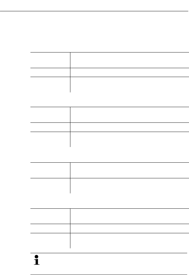
6 Using the product
92 0970 4020 en 01 testo AG
6.2.3. Options
Pos: 112 /TD/Produkt verwenden/testo Saver is/02 Menüs und Befehle der Ribbon-Leiste/03 E xtras/01 Verwaltung @ 1\mo d_1197373808453_7 9.doc @ 6173
Extras | Management menu
Menu
function
Description
Projects Opens the dialogue for selecting a project.
Protocols Opens a protocol file that you can send to
Customer Service in the event of a problem.
Pos: 113 /TD/Produkt verwenden/testo Saver is/02 Menüs und Befehle der Ribbon-Leiste/03 E xtras/02 Bearbeiten @ 0\mod_ 1189606801796_79.d oc @ 4596
Extras | Edit menu
Menu
function
Description
Undo Undo the last action.
Paste into a
new file
Pastes the content on the clipboard in a new
file.
Pos: 114 /TD/Produkt verwenden/testo Saver is/02 Menüs und Befehle der Ribbon-Leiste/03 E xtras/03 Einstellung en @ 0\mod_1189606889031_ 79.doc @ 4616
Extras | Settings menu
Menu
function
Description
Representatio
n
Settings for the representation of the diagram.
Pos: 115 /TD/Produkt verwenden/testo Saver is/02 Menüs und Befehle der Ribbon-Leiste/03 E xtras/04 Schriftar t @ 0\mod_118960671954 6_79.doc @ 4576
Extras | Font menu
Menu
function
Description
Font Setting the font for the tables and diagrams.
Font size Setting the font size for the tables and
diagrams.
When selecting the font and font size, take into account
the legibility of the diagrams and tables. Use sans-serif
fonts such as Arial or Verdana.
Pos: 116 /TD/Produkt verwenden/testo Saver is/02 Menüs und Befehle der Ribbon-Leiste/03 E xtras/05 Servicedaten @ 0\ mod_1189606938750_ 79.doc @ 4626
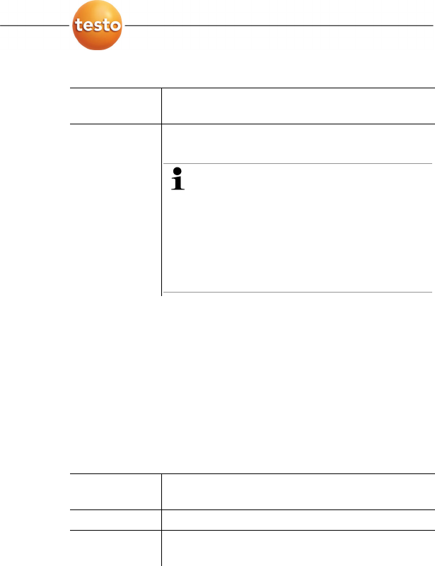
6 Using the product
0970 4020 en 01 93
Extras | Service menu
Menu
function
Description
Display
service data
Creates a text file with the required information
for Customer Service if servicing is required.
If the service data cannot be displayed
under Windows® Vista, start the
WordPad program and save, for
example, an empty file of your choice in
*.wri format. To do so, manually enter
the file extension behind the file name.
A link is thus formed between the file
and the service data and WordPad.
Pos: 117 /TD/Produkt verwenden/testo Saver is/02 Menüs und Befehle der Ribbon-Leiste/05 Menü Vorlage @ 0\mod_1190280 258593_79.doc @ 5013
6.2.4. Template
Pos: 118 /TD/Produkt verwenden/testo Saver is/02 Menüs und Befehle der Ribbon-Leiste/05 Vorl age @ 0\mod_118899703328 1_79.doc @ 3727
Template | Template menu
Select a standard template in this menu into which the data that
are to be saved or printed are integrated.
The templates differ in the protocol header, meaning in the
company logo, the address field or the specification of statistical
values.
Template | Edit menu
Menu
function
Description
Edit template Enables the editing of an existing template.
Create new
template
Enables the creation of a new template.
Pos: 119 /TD/Produkt verwenden/testo Saver is/02 Menüs und Befehle der Ribbon-Leiste/06 Menü Style @ 0\mod_119037835 6765_79.doc @ 5092
6.2.5. Style
Selection of the colour scheme for the program window.
Pos: 120 /TD/Produkt verwenden/testo Saver is/02 Menüs und Befehle der Ribbon-Leiste/07 Menü Hilfe @ 0\mod_11903785422 50_79.doc @ 5102
6.2.6. Help (?)
Display copyright, program information and version number.
Pos: 121 /TD/Produkt verwenden/testo Saver is/03 Gruppen einric hten/organisieren/0 0 Zonen anlegen und lösc hen @ 0\mod_1190280348609_7 9.doc @ 5023
6 Using the product
94 0970 4020 en 01 testo AG
6.3. Creating and deleting zones
After you have familiarized yourself with the menus of the
Saveris software you can now turn to creating zones, for
example to separate the probes according to location. You
could perhaps combine probes that are located in store rooms
into one zone and probes that are in cold rooms into another.
Pos: 122 /TD/Produkt verwenden/testo Saver is/03 Gruppen einric hten/organisieren/0 4 Zonen anlegen @ 0\mod_11890 76726062_79.doc @ 3902
6.3.1. Creating zones
1. Click on Data in the navigation area.
- The available zones are shown in the data range.
2. Select the New zone command in the Start | Edit |
Organizing menu.
- The New zone dialogue is shown.
3. If necessary, deactivate an unneeded channel.
At least one channel must be activated.
When you create a new zone, create a copy with one or
more channels from the Zone0 standard group.
4. In the field of the same name, enter the name of the new
zone, e.g. "Store rooms".
Assign names for the zones that are not longer than 15
characters.
5. Confirm the entries with [OK].
- The
New zone dialogue is closed and the new zone is listed
in the tree structure in the data range.
Pos: 123 /TD/Produkt verwenden/testo Saver is/03 Gruppen einric hten/organisieren/0 8 Zonen löschen @ 0\mod_1189 076727046_79.doc @ 3922
6.3.2. Deleting zones
The Zone0 standard group cannot be deleted.
1. Click on Data in the navigation area.
- The available zones are shown in the data range.
2. Mark the zone that is to be deleted in the tree structure.
3. Select the Erase command in the Start | Edit menu.
- The zone is deleted without a reference.
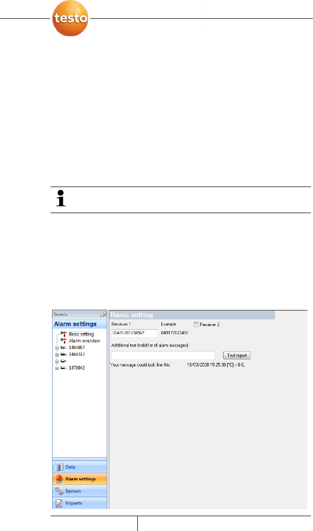
6 Using the product
0970 4020 en 01 95
Pos: 124 /TD/Produkt verwenden/testo Saver is/04 Alarme konfigur ieren/00 Alarme konfi gurieren @ 0\mod_1189063 396359_79.doc @ 3852
6.4. Configuring the alarms
The testo Saveris measurement system differentiates between
two types of alarm, which can be configured independent of
one another:
• System alarms, meaning alarms that come from the Saveris
base, the GSM modem or the relay at the Saveris base, and
• Probe alarms, which report a fault or that a limit value was
exceeded at a probe.
Pos: 125 /TD/Produkt verwenden/testo Saver is/04 Alarme konfigur ieren/01 Alarm vorkonf igurieren @ 0\mod_1188 997882750_79.doc @ 3781
6.4.1. Basic settings for the SMS messages
The Basic settings submenu is only shown if the
Saveris base is equipped with a GSM module.
1. Click on Alarm settings in the navigation area.
- In the data window, the Basic setting and Alarm overview
submenus as well as the probes connected in the Saveris
base are shown.
2. Click on Basic setting.
- The basic settings for the alarm messages via SMS are
shown in the display range.
Designation Description
6 Using the product
96 0970 4020 en 01 testo AG
Designation Description
Receiver 1 Telephone number of the employee who
is to receive the alarm message. Enter
with country code, network or area code
and local number: 00491721234567.
To acknowledge an alarm
message, send the received
message with the same text back
to the mobile number of the
Saveris base.
Receiver 2 Checkbox and input field for the
telephone number of the employee who is
to receive the alarm message if Receiver
1 cannot be reached. Enter with country
code, network or area code and local
number: 00491721234567.
To acknowledge an alarm
message, send the received
message with the same text back
to the mobile number of the
Saveris base.
Forward after ...
min
If Receiver 1 does not react within this
time span, the message is forwarded to
Receiver 2.
Additional text Additional text that is attached to the
alarm message.
The system alarms are above all used for pointing out
irregularities in the measurement system. If no reaction
follows the system alarms, uninterrupted data recording
is not guaranteed.
If a system alarm is issued via SMS or E-mail time
delays may occur.
The notification function via SMS is only available if the
Saveris base is equipped with a GSM module.
3. Perform the required settings.
When exiting the basic settings the settings are saved.
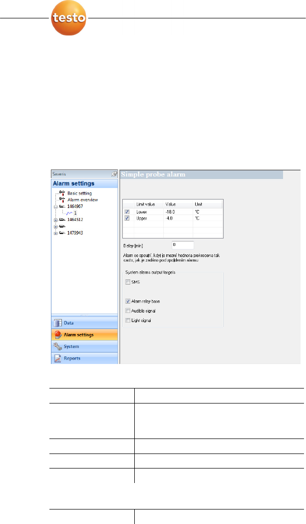
6 Using the product
0970 4020 en 01 97
Pos: 126 /TD/Produkt verwenden/testo Saver is/04 Alarme konfigur ieren/02 Spezifi schen Alarm einrichten @ 0\m od_1189064215593_79. doc @ 3861
6.4.2. Configuring the probe alarm
1. Click on Alarm settings in the navigation area.
- In the data window, the Basic setting and Alarm overview
submenus as well as the probes connected in the Saveris
base are shown.
2. In the tree structure open the probe entry and select the
channel for which a specific alarm should be set up.
- The channel-specific settings for the alarms are shown in
the display range.
Pos: 127 /TD/Produkt verwenden/testo Saver is/04 Alarme konfigur ieren/02 Spezifi scher Alarm - 01 Grenzwerte @ 0\ mod_1189064521015_79. doc @ 3871
Limit values
Designation Explanation
Checkbox Option of whether an alarm should be
triggered in the event of a breach of the
limit value.
Limit value Designation of the limit value.
Value Specification of the limit value.
Unit Unit of the limit value.
Pos: 128 /TD/Produkt verwenden/testo Saver is/04 Alarme konfigur ieren/02 Spezifi scher Alarm - 02 Verzögerung @ 0\ mod_1189064581156_79. doc @ 3881
Alarm delay
Designation Explanation
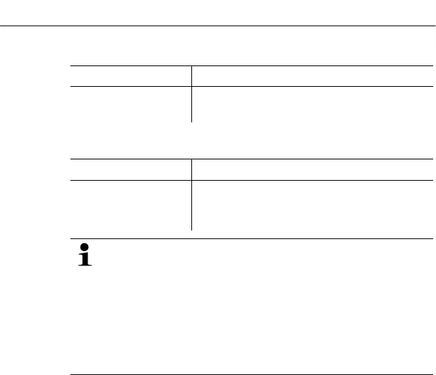
6 Using the product
98 0970 4020 en 01 testo AG
Designation Explanation
Delay (min) With a delay of how many measuring
cycles should the alarm be triggered?
Pos: 129 /TD/Produkt verwenden/testo Saver is/04 Alarme konfigur ieren/02 Spezifi scher Alarm - 03 Ausgabe @ 0\mod_ 1189064615828_79.doc @ 3891
Output targets
Designation Explanation
SMS,
E-mail,
Alarm relay base,
Determining in which form the probe
alarms should be issued.
The system alarms are above all used for pointing out
irregularities in the measurement system. If no reaction
follows the system alarms, uninterrupted data recording
is not guaranteed.
If a system alarm is issued via SMS or E-mail time
delays may occur.
The notification function via SMS is only available if the
Saveris base is equipped with a GSM module.
> Make the required entries.
When exiting the probe settings the changes are saved.
Pos: 130 /TD/Produkt verwenden/testo Saver is/04 Alarme konfigur ieren/03 Alarmübersi cht @ 0\mod_1188997883 484_79.doc @ 3791
6.4.3. Alarm overview
In the alarm overview you will find a list of the probes with their
specific alarm settings.
1. Click on Alarm settings in the navigation area.
- In the data window, the Basic setting and Alarm overview
submenus as well as the probes connected in the Saveris
base are shown.
2. Click on Alarm overview.
- The probes are listed with their specific settings in the
display range.
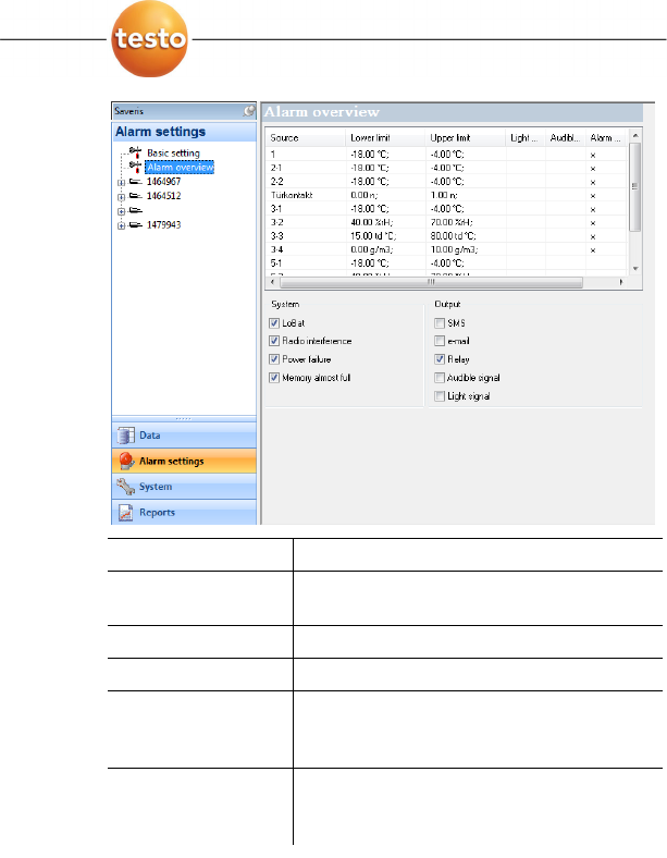
6 Using the product
0970 4020 en 01 99
Designation Explanation
Source Probes on which the limit value has been
exceeded.
Lower limit Lower limit value.
Upper limit Upper limit value.
SMS,
E-mail,
Alarm relay base,
Specification as to whether the
corresponding option is activated in the
basic settings.
Active Specification as to whether the alarm for
the probe is activated under System |
Radio probe.
Pos: 131 /TD/Produkt verwenden/testo Saver is/05 Messreihen ana lysieren @ 0\mod_119089585 9625_79.doc @ 5163

6 Using the product
100 0970 4020 en 01 testo AG
6.5. Analyzing series of measurements
You can represent series of measurements as a diagram or a
table.
> In the
Start | View menu, select the
• Diagram function if the data should be displayed
graphically or
• Table function if the data should be displayed as a table.
Pos: 132 /TD/Produkt verwenden/testo Saver is/05a Diagramme analy sieren/00 Diagramme @ 0\m od_1188996581406_7 9.doc @ 3484
6.5.1. Diagram view
In this view, the readings are shown as line diagrams.
In the Start | View menu, the Diagram command is activated.
Now you have to select the data record that you wish to display.
1. Select the day or time period in the calendar that should be
evaluated.
2. In the tree structure of the data range, open the group that
contains the data to be displayed.
- The diagram for the selected data is shown.
> If necessary, deactivate channels via the checkboxes for the
display.
You can show or hide the gridlines for the
corresponding axis by clicking on the time axis or the
value axis.
Pos: 133 /TD/Produkt verwenden/testo Saver is/05a Diagramme analy sieren/01 Vergrößer n @ 0\mod_1188996582156_7 9.doc @ 3494
6.5.1.1. Enlarging the view
Zoom in on a detail of the diagram to check the behavior of the
readings within a specific time span, for example.
1. Click on Edit | Tools | Zoom in.
2. In the diagram, use the left mouse button, pressed and held,
to highlight the area that should be shown enlarged.
Click on [Original size] and the entire diagram is
shown again.
Pos: 134 /TD/Produkt verwenden/testo Saver is/05a Diagramme analy sieren/02 Fadenkreuz @ 0\ mod_1188996582421_79. doc @ 3504

6 Using the product
0970 4020 en 01 101
6.5.1.2. Information on a reading (crosshairs)
If you move your crosshairs along a curve, you will quickly
receive detailed information on the individual readings.
1. Click on Edit | Tools | Crosshairs.
2. In the diagram, click on the point for which the details should
be shown.
- A dialogue with the following information on the reading is
shown:
• date on which the reading was recorded,
• time at which the reading was recorded,
• number of the reading and
• reading.
You can move along the curve with the left mouse
button pressed and held and thereby see the individual
information for the readings.
In doing this, it is not necessary to exactly follow the
course of the curve; the crosshairs does this
automatically if you move the mouse to the right or left.
Pos: 135 /TD/Produkt verwenden/testo Saver is/05a Diagramme analy sieren/03 Bereic h markieren @ 0\mod_11889965 82687_79.doc @ 3514
6.5.1.3. Marking the area
Mark an area of the diagram to show the statistical computation
for a portion of the curve, for example.
1. Click on Edit | Tools | Mark area.
2. In the diagram, click in the area on the curve that is to be
marked.
- A border is shown that marks the area.
You can
• change the borders of the area by holding down the left
mouse button and
• move the area to the left or right by pressing down the right
mouse button within the area.
The arithmetic mean for the selected area is shown as a
horizontal line in the diagram.
In the status bar, the borders of the area, the mean and
the minimum and maximum reading are shown.
> Delete the marked area with the Erase text command.
6 Using the product
102 0970 4020 en 01 testo AG
Pos: 136 /TD/Produkt verwenden/testo Saver is/05a Diagramme analy sieren/04 Ausgleic hskurve @ 0\mod_1188996 582968_79.doc @ 3524
6.5.1.4. Showing regression curve
Place the regression curve over the diagram to show the course
that the measurement series tends to take.
1. Click on Edit | Tools | Regression curve.
2. Click on the reading curve for which the regression curve
should be shown.
- The regression curve is shown and displayed in the status
bar of its regression coefficients.
If you click on the curve again, the regression curve is
hidden again.
Pos: 137 /TD/Produkt verwenden/testo Saver is/05a Diagramme analy sieren/05 Text einfügen @ 0\mod_118899658325 0_79.doc @ 3534
6.5.1.5. Inserting text
Insert text in the diagram, for example to mark distinctive
measurement points.
1. Click on Edit | Tools | Insert text.
- A text field is inserted in the diagram.
2. Enter any text.
3. Drag text field to required position in the diagram with left
mouse button pressed and held on the upper horizontal
border of the field.
The text length possible depends on the size of the text
field. Enlarge the text field by dragging the vertical
borders of the field or the lower horizontal border of the
field with the left mouse button pressed and held.
With one click of the right mouse button on the text field,
you open the Font dialogue in which you can format the
text.
When selecting the font, font size and colour, take into
account the legibility of the text. Use sans-serif fonts
such as Arial or Verdana as well as a text colour that is
clearly visible against the background colour.
Pos: 138 /TD/Produkt verwenden/testo Saver is/05a Diagramme analy sieren/06 Text entfer nen @ 0\mod_1188996583546_ 79.doc @ 3544

6 Using the product
0970 4020 en 01 103
6.5.1.6. Erasing text
You also delete a marked area from the diagram with
the Erase text command.
1. Click on the text that is to be erased.
- The text field is marked.
2. Click on Edit | Tools | Erase text.
- The text field is deleted.
Pos: 139 /TD/Produkt verwenden/testo Saver is/05a-2 Kurveneigensc haften/00 Kur veneigenschaften @ 0\mod_1 188996704171_79.d oc @ 3636
6.5.1.7. Characteristics of a curve
You can adapt the representation of a measurement series to
your requirements. For example, you can change the line
weight of a curve or the representation of the limit values in the
diagram.
1. Change to the diagram view of the measurement series, the
characteristics of which are to be displayed.
2. Click in the Edit | Curves menu on the entry of the curve,
the characteristics of which are to be displayed.
- The
Characteristics of (name of curve) dialogue is
opened.
The following tabs are available in the dialogue:
• Curve tab
• Range limits tab
• Data sequence tab
• Statistical computation tab.
Buttons of the dialogue
Button Explanation
[OK] Applies the changed settings. The
dialogue is closed.
[Cancel] Closes the dialogue without applying the
changes.
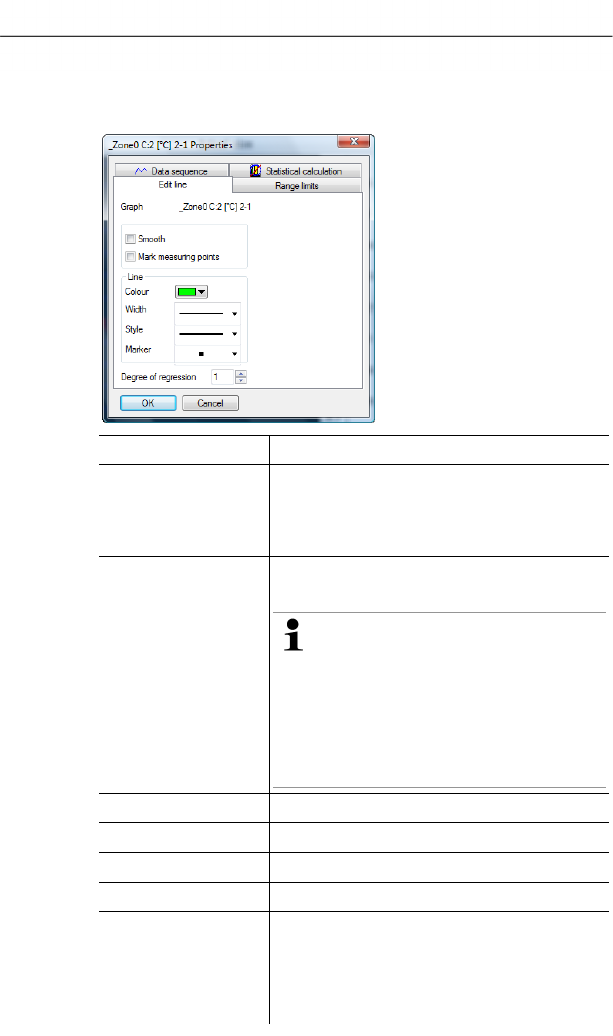
6 Using the product
104 0970 4020 en 01 testo AG
Pos: 140 /TD/Produkt verwenden/testo Saver is/05a-2 Kurveneigensc haften/01 Register Kurve bearbeiten @ 0\mod_1 188996705609_79.d oc @ 3666
Curve tab
Designation Explanation
Smooth The measurement points are connected
by an interpolated curve; the plot-points
on the curve between two measurement
points are estimated mathematically.
Mark measuring
points
The individual measurement points are
represented by a symbol.
The value shown only
corresponds to the exact
measured value at these points.
The measurement points are
connected with straight lines
during the measurement. When
the measurement is paused the
curve can be smoothed.
Colour Line colour of curve.
Width Line weight of curve.
Style Line pattern of curve.
Marker Symbol for the measurement points.
Degree of
regression
Possible values "0" to "7". The "0" degree
represents a pure mean calculation, the
"1" degree of regression the linear trend,
a higher value helps in the event of
curves with several extreme values.
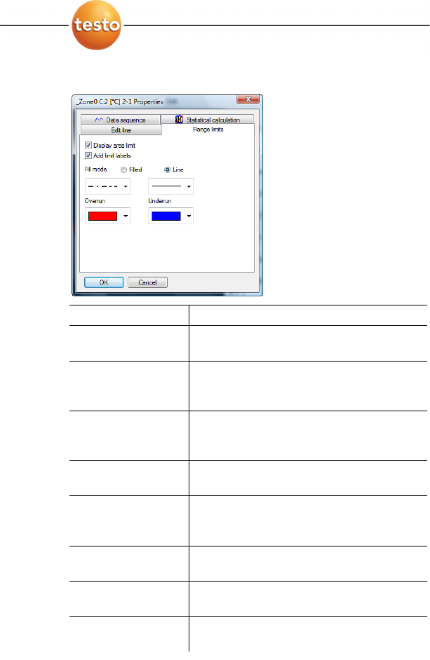
6 Using the product
0970 4020 en 01 105
Pos: 141 /TD/Produkt verwenden/testo Saver is/05a-2 Kurveneigensc haften/02 Register Grenzwertanzeige @ 0\mod_1188996705265_7 9.doc @ 3656
Range limits tab
Designation Explanation
Display area limit Specification as to whether the limit
values should be shown in the diagram.
Add limit labels Specification as to whether the limit
values should be labelled (Upper/Lower
limit value: name of curve).
Area fill Specification as to whether the areas
outside of the limit values should be
marked by means of an area fill.
Selection list for
area fill
Selection of the fill.
Line fill Specification as to whether the limit
values should by means of horizontal
lines.
Selection lists for
line fill
Selection lists for line type and line
thickness.
Overshoot Colour selection for the fill of the area
above the upper limit value.
Undershoot Colour selection for the fill of the area
below the lower limit value.
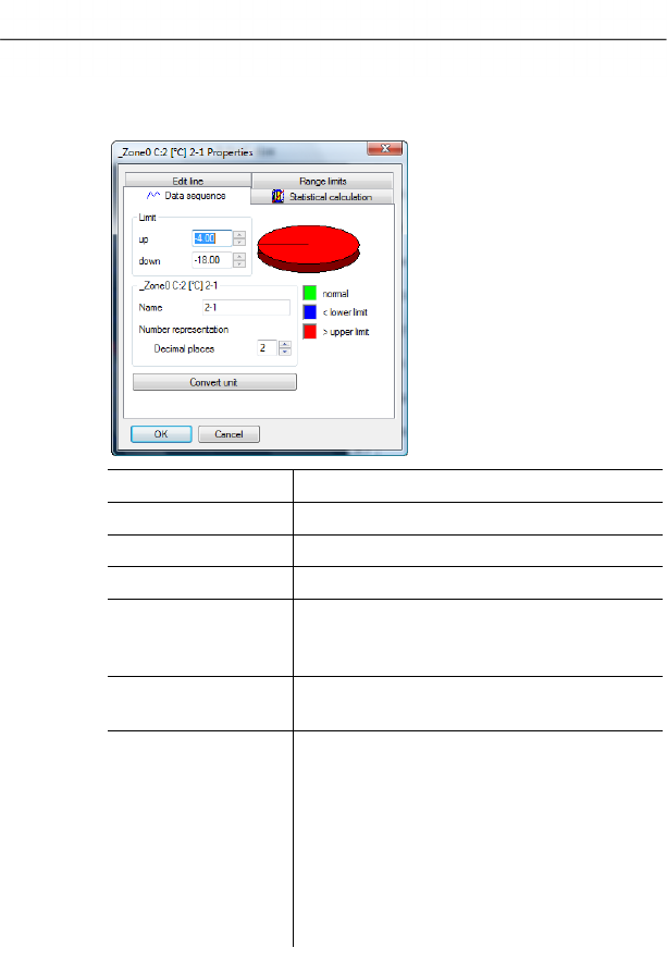
6 Using the product
106 0970 4020 en 01 testo AG
Pos: 142 /TD/Produkt verwenden/testo Saver is/05a-2 Kurveneigensc haften/03 Register Datenreihe @ 0\mod_11 88996704453_79.doc @ 3646
Data sequence tab
Designation Explanation
Upper limit values Specification of the upper limit value.
Lower limit values Specification of the lower limit value.
Name Designation of curve.
Decimal places
number
representation
Number of the decimal places; e.g. for the
data table. Possible values "0" to "6".
[Convert unit] Opens a dialogue for converting the unit
of the curve.
Pie chart Graphical representation for the
distribution of the readings:
• green: readings that are within the
limit values.
• blue: readings that are below the
lower limit value.
• red: readings that are above the
upper limit value.
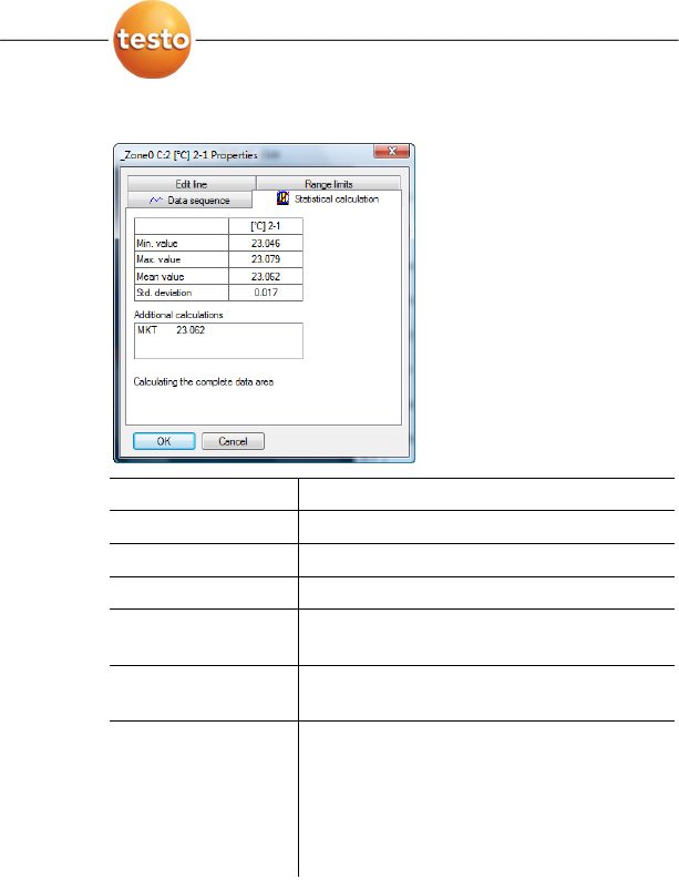
6 Using the product
0970 4020 en 01 107
Pos: 143 /TD/Produkt verwenden/testo Saver is/05a-2 Kurveneigensc haften/04 Register Stat. Berechnung @ 0\mod_1 188996705906_79.d oc @ 3676
Statistical computation tab
Designation Explanation
Min. value Smallest reading of the curve.
Max. value Largest reading of the curve.
Mean value Arithmetically-determined average value.
Std. deviation Measure of the scattering of the readings
around the average.
Calculating the
complete data area
Specification that the given values are
valid for the entire measurement curve.
Calculation in
section area
An alternative to Calculating the
complete data area, if an area was
marked.
Specification that the given values are
only valid for the selected area of the
measurement curve.
Pos: 144 /TD/Produkt verwenden/testo Saver is/05a-3 Achseins tellungen/05 Einstel lungen für die Achsen im Di agramm @ 0\mod_119399954216 8_79.doc @ 5684
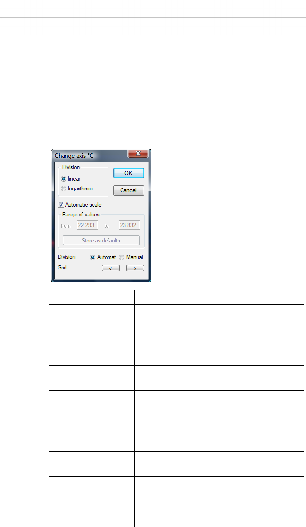
6 Using the product
108 0970 4020 en 01 testo AG
6.5.1.8. Settings for the axes in the diagram
Change the settings of the axes in the diagram to adapt the
representation to your requirements.
Pos: 145 /TD/Produkt verwenden/testo Saver is/05a-3 Achseins tellungen/06 Wer teachse @ 0\mod_1193999542824_ 79.doc @ 5694
Settings for the value axis
> With the right mouse button, click on the desired value axis
in the diagram.
- The Change axis [unit of the readings] dialogue is shown.
Designation Explanation
Division linear Specification that the axles are divided in
a linear manner.
Division
logarithmic
Specification that the axes are divided
logarithmically, meaning the increments
represent powers of ten.
[OK] Applies the settings until other data are
called up. The dialogue is closed.
[Cancel] Closes the dialogue without applying any
changes.
Automatic scale Specification as to whether the program
should perform the scaling of the value
axis.
Range of values
from ... to
Manual entry of the range of values if the
Automatic scale is deactivated.
[Store as defaults] Saves the current settings as the default
setting.
Division Automat. Specification that the program should
perform the division of the axis.
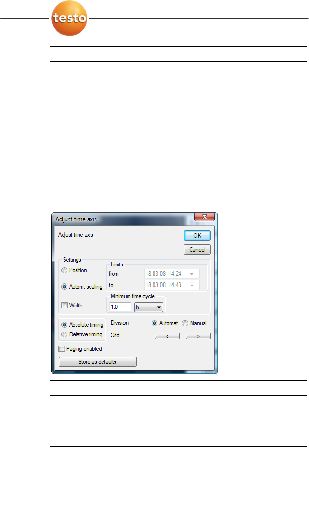
6 Using the product
0970 4020 en 01 109
Designation Explanation
Division Manual Specification that the division of the axis
should be performed manually.
Grid [<], [>] (if
automatic division is
activated)
Decrease or increase the division of the
axis by clicking on [<] or [>].
Interval (if manual
division is activated)
Manual entry of the grid.
Pos: 146 /TD/Produkt verwenden/testo Saver is/05a-3 Achseins tellungen/07 Zeitachs e @ 0\mod_1193999544199_7 9.doc @ 5704
Settings for the time axis
> With the right mouse button, click on the time axis in the
diagram.
- The Adjust time axis dialogue is shown.
Designation Explanation
[OK] Applies the settings until other data are
called up. The dialogue is closed.
[Cancel] Closes the dialogue without applying any
changes.
Position Shows a freely-definable extract of the
diagram.
Autom. scaling... Shows the entire diagram in the window.
Extract Shows a fixed, defined extract that can be
moved over the time axis.

6 Using the product
110 0970 4020 en 01 testo AG
Designation Explanation
Limits from ... to (if
Position view is
activated)
Limits for the Position view.
Minimum time
cycle (if Extract
view is activated)
Specification of which time period should
at least be shown.
Selection list for
the unit (if Extract
view is activated)
Unit of the time axis in the minimum time
cycle:
• sec (second)
• min (minute)
• h (hour)
• d (day).
Absolute All times are the real times at which the
readings were recorded.
Relative Sets the starting time to 00:00; the time
the runs relative to this starting point.
Paging enabled The function associated with this is not
available in the Small Business Edition.
[Store as defaults] Saves the current settings as the default
setting.
Division Automat. Specification that the program should
perform the division of the axis.
Division Manual Specification that the division of the axis
should be performed manually.
Grid [<], [>] (if
automatic division is
activated)
Decrease or increase the division of the
axis by clicking on [<] or [>].
Interval (if manual
division is activated)
Manual entry of the grid.
Selection list for
the unit (if manual
division is activated)
Unit of the time axis:
• sec (second)
• min (minute)
• h (hour)
• d (day).
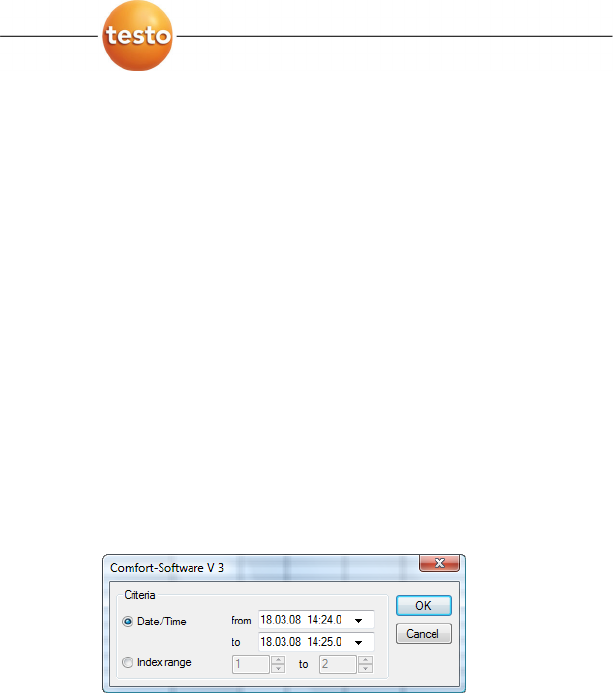
6 Using the product
0970 4020 en 01 111
Pos: 147 /TD/Produkt verwenden/testo Saver is/05b Tabellen analy sieren/00 Tabellen @ 0\ mod_1188996635000_79. doc @ 3555
6.5.2. Table view
The readings are listed in table form in this view.
In the Start | View menu, the Table command is activated. Now
you have to select the data record that you wish to display.
1. Select the day or time period in the calendar that should be
evaluated.
2. In the tree structure of the data range, open the zone that
contains the data to be displayed.
- The table view of the selected data is shown.
> If necessary, deactivate channels via the checkboxes for the
display.
Pos: 148 /TD/Produkt verwenden/testo Saver is/05b Tabellen ana lysieren/01 Messwerte mar kieren @ 0\mod_11889966 35625_79.doc @ 3565
6.5.2.1. Marking readings
Mark specific readings to perform a statistical computation for
part of the measurement series, for example.
1. Click on Edit | Tools | Mark.
- A dialogue for determining the criteria is shown.

6 Using the product
112 0970 4020 en 01 testo AG
2. Select the
• Select
Date/time if the readings for a particular time
period are to be marked.
- The selection lists are enabled for the determination of
the time period.
• Select the
Index range if the readings in particular rows
in the table are to be marked.
- The selection lists are enabled for the determination of
the index range.
3. Determine time period or index range.
4. Click on [OK].
- The dialogue is closed and the corresponding readings are
marked in the table.
You can also mark readings with the mouse, as you are
familiar with from Office applications.
Pos: 149 /TD/Produkt verwenden/testo Saver is/05b Tabellen ana lysieren/02 Markierung a ufheben @ 0\mod_1188996 637078_79.doc @ 3575
6.5.2.2. Dropping the marking
> Click on Edit | Tools | Drop marking.
- The marking of the readings is deleted.
Pos: 150 /TD/Produkt verwenden/testo Saver is/05b Tabellen ana lysieren/03 Extremwert o der Mittelwert einfüg en @ 0\mod_11889966378 90_79.doc @ 3585
6.5.2.3. Inserting extreme values or mean in the table
Insert the minimum/maximum reading as well as the mean from
the whole table at the end of the table.
1. Click on Edit | Tools | Extra lines | Minimum, Maximum or
Mean value.
- A row with the corresponding value for all readings is
inserted at the end of the table.
> Repeat step 1 to insert another value in the table.
To erase a value from the table again, click in the Extra
lines menu again on the corresponding entry.
Pos: 151 /TD/Produkt verwenden/testo Saver is/05b Tabellen ana lysieren/04 Verdic hten @ 0\mod_1188996638437_ 79.doc @ 3595
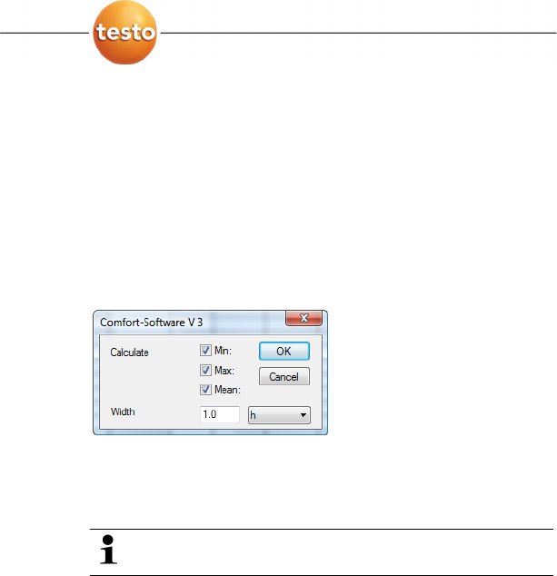
6 Using the product
0970 4020 en 01 113
6.5.2.4. Compressing readings
Compress the table to definable intervals to maintain the clarity
of the table with large amounts of data.
Only the first and the last value are shown for the individual
intervals. The other readings are hidden.
In addition, the minimum, maximum and/or average value can
be shown for the respective time period.
1. Click on Edit | Tools | Compress.
- The dialogue for determining the options is opened.
> Use the checkboxes to determine whether the respective
minimum reading (Min), maximum reading (Max) and/or
average value (Mean) should be calculated for the individual
time spans.
At least one of these values must be activated to be
able to perform the compression of the table.
2. Enter the time span under Extract and determine its unit.
Possible settings for the unit:
• sec (second)
• min (minute)
• h (hour)
• d (day).
3. Click on [OK].
- The dialogue is closed and the table is shown compressed.
Pos: 152 /TD/Produkt verwenden/testo Saver is/05b Tabellen ana lysieren/05 Verdic htung aufheben @ 0\mod_11889 96639140_79.doc @ 3605
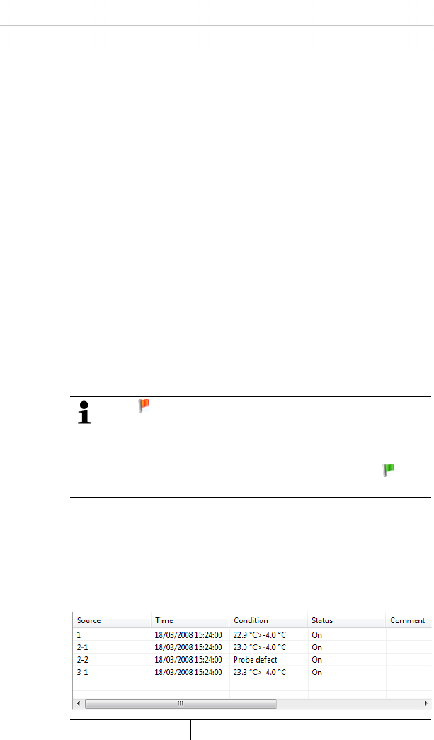
6 Using the product
114 0970 4020 en 01 testo AG
6.5.2.5. Dropping compression
> Click on Edit | Tools | Drop compression.
- The table is shown again in its uncompressed form.
Pos: 153 /TD/Produkt verwenden/testo Saver is/05b Tabellen ana lysieren/07 größter Mess wert @ 0\mod_11889966398 59_79.doc @ 3625
6.5.2.6. Determining largest reading
> In the Edit | Find | Maximum menu click on the curve for
which the largest reading should be determined.
- The largest reading is shown marked in the table.
Pos: 154 /TD/Produkt verwenden/testo Saver is/05b Tabellen ana lysieren/08 Kleinster M esswert @ 0\mod_118899 6639562_79.doc @ 3615
6.5.2.7. Determining the smallest reading
> In the Edit | Find | Minimum menu click on the curve for
which the smallest reading should be determined.
- The smallest reading is shown marked in the table.
Pos: 155 /TD/Produkt verwenden/testo Saver is/06c Alarme analy sieren/00 Alarme analysi eren @ 0\mod_11890790973 12_79.doc @ 3954
6.6. Analyzing alarms
If system or probe alarms were triggered by the Saveris base,
you can check the alarms and subsequently confirm
(acknowledge) them.
The symbol in the display range of the task bar also
you that an alarm was issued by the Saveris base, even
with the software closed. If you move to the symbol with
the mouse information is shown regarding the alarm.
If an alarm is not triggered, this is shown by the
symbol.
Pos: 156 /TD/Produkt verwenden/testo Saver is/06c Alarme analy sieren/01 Alarme prüfen @ 0\ mod_1189079390359_79. doc @ 3963
6.6.1. Checking alarms
> In the diagram or table view under Start | View mark the
Alarms option.
- The alarms received are shown in the Overview below the
diagram or the table.
>
Designation Explanation
6 Using the product
0970 4020 en 01 115
Designation Explanation
Source
Probes on which the breach of the limit
value has occurred.
Time Date and time at which the message is
received.
Condition Condition that was fulfilled so that the
alarm was triggered; e.g. Limit value
overrun.
Status Date and time, when the alarm was
triggered.
Comments Any comments on the alarm.
Tel. number/name Telephone number or recipient for the
alarm message
> If needed, enter Comments on an alarm in the column of
the same name.
Pos: 157 /TD/Produkt verwenden/testo Saver is/06c Alarme analy sieren/02 Alarm quitti eren @ 0\mod_11890794363 28_79.doc @ 3973
6.6.2. Acknowledge the alarm
If you acknowledge an alarm at the Saveris base, this is
carried over into the software.
If you have received an alarm message by SMS, you
can acknowledge the alarm by sending the received
SMS with the same text back to the mobile number of
the Saveris base.
> Switch to the Acknowledgement tab in the calendar and
acknowledgement section.
- The list of the registered channels is shown.
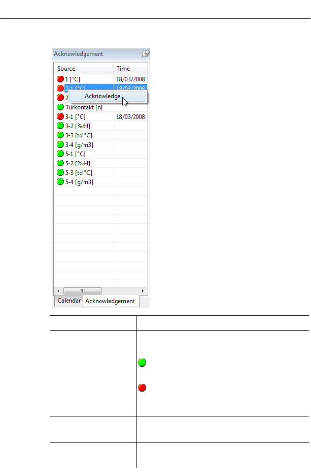
6 Using the product
116 0970 4020 en 01 testo AG
Designation Explanation
Source
Designation of the individual channels of
the registered probes.
The channel delivers measurement
data within the limit values.
A limit value has been breached
and the Saveris base has triggered an
alarm.
Time Date and time, when the alarm was
triggered.
Condition Condition that was fulfilled so that the
alarm was triggered.
4. Click with the right mouse button on the alarm entry that is
to be confirmed and select the Acknowledge command in
the context menu.
- The
Acknowledgement dialogue is opened.
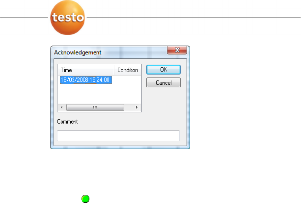
6 Using the product
0970 4020 en 01 117
5. Mark the entry of the alarm that should be acknowledged.
6. If needed, enter Comments on the alarm in the field of the
same name and confirm the alarm with [OK].
- The symbol shows that the alarm was confirmed and the
comments are carried over in the alarm list in the display
range.
The confirmation of the alarm is transmitted to the Saveris
base. As soon as the confirmation is received in the Saveris
base, the alarm relay stops flashing and the alarm is
deleted.
Pos: 158 /TD/Produkt verwenden/testo Saver is/07 Berichte/00 Ber ichte erstellen @ 0\mod _1190280535671_79.doc @ 5032
6.7. Creating evaluations
You can print out series of measurements or have reports on
the data automatically created by the software in definable
intervals.
Pos: 159 /TD/Produkt verwenden/testo Saver is/07 Berichte/01 Ber icht drucken @ 0\mod_1189522 120546_79.doc @ 4294
6.7.1. Printing measurement data
Measurement data can be printed in diagram or table form.
1. Select the day or time period in the calendar for which the
report should be created.
- The data for the day or the time period are shown as a
diagram or table, depending on the setting.
> In the
Start | View menu, select the
• Diagram command if the table view is activated but the
diagram view should be printed.
• Table command if the diagram view is activated but the
table view should be printed.
6 Using the product
118 0970 4020 en 01 testo AG
2. Select the type of report head in the Template | Template
menu.
Open the preview of the report using the File (Testo
logo) | Print preview command.
Use portrait format for printing a table and landscape
format for printing a diagram.
You can determine the format under File | Page
Setup....
3. Select the Print command in the File menu.
- The
Print dialogue for selecting the printing options is
shown.
4. Change printing options, if needed, and click on [OK].
- The report is printed.
The report head contains the following information:
• title,
• number of pages,
• date,
• start and end time for a measurement (only for
tables),
• specification of the extreme values and the mean
value for every curve,
• number of channels and readings (only for tables),
• input options for "Conditions" and
• other comment lines.
Pos: 160 /TD/Produkt verwenden/testo Saver is/07 Berichte/02 * * Automatische Beric hte @ 0\mod_1189522147015_7 9.doc @ 4304
6.7.2. Archiving with automatic reports
A simple and secure option for archiving your data is the
automatic creation of reports.
The reports are created by the software and recorded on a
daily, weekly or monthly basis at a specified location on the
computer or a server; also see the chapter "Report settings" for
this.
The reports are saved as PDF files so that they can easily be
read or sent per e-mail but without being able to change the
data stock.
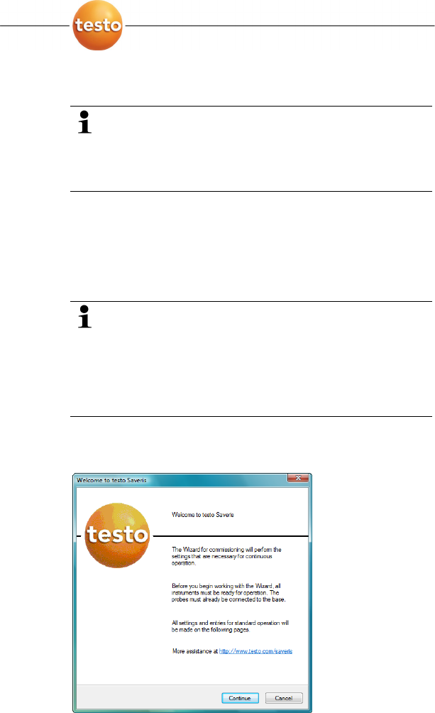
6 Using the product
0970 4020 en 01 119
Pos: 161 /TD/Produkt verwenden/testo Saver is/07 Berichte/03 * * Langzeitarchivierun g und Datensicherung @ 0\m od_1190970854000_79. doc @ 5223
6.8. Creating a new database (project)
The licence-free database system Microsoft SQL Server
2005 Express is installed as standard with the testo
Saveris software.
The Microsoft SQL Server 2005 Express can manage
databases up to a size of 4 GB.
Before reaching the maximum capacity of the database, you
receive a warning message from the Saveris software in good
time in which you are made aware of the remaining life.
In this case, close the database by ending and saving the
current project and create a new project, and thus a new
database.
The possible duration of the recording is primarily
determined by the measuring rate with a constant
number of channels.
If the Saveris base, for example, records the data from
20 channels with a measuring rate of 2 minutes, the
database can save data for longer than ten years in this
configuration.
1. Under Start | All Programs | Testo click on Saveris
Startup Assistant.
- The welcome dialogue of the startup assistant is shown.
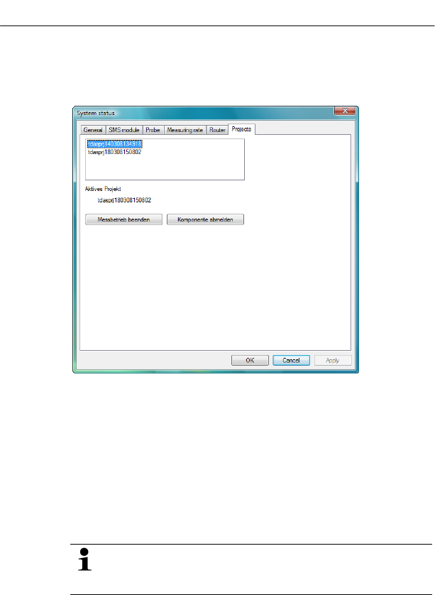
6 Using the product
120 0970 4020 en 01 testo AG
2. Click on [Continue >].
- The
System status dialogue with the General tab is shown.
3. Change to Projects tab.
4. Mark the project that is to be ended and click on [End
Measuring Mode].
- A notification is shown in which you must confirm the reset
of Saveris base to the basic configuration.
5. Click on [Yes] to reset the Saveris base to the basic
configuration.
- All components are deleted from the Saveris base and the
project is closed in the Saveris software.
To be able to start a new project, you must reconnect all
components to the Saveris base and then start up the
hardware again.
Pos: 162 /TD/Produkt verwenden/testo Saver is/09 Einstellungen Sy stem/00 Einstellu ngen System @ 0\mod_11894937 29343_79.doc @ 4233

6 Using the product
0970 4020 en 01 121
6.9. System settings
In this menu, determine the settings for the Saveris base, the
radio probes and – if installed in the measuring system – the
Ethernet probes, router and converter.
> Click on
System in the navigation area.
- The following entries are shown in the tree structure in the
data range:
• Base with the general settings of the Saveris base and
the SMS module (if present) as well as the operating
data of the probes.
• Radio probe with the settings for the radio probes
connected to the Saveris base.
• Ethernet probe with the settings for the Ethernet probes
attached to the Saveris base.
• Router with the settings for the routers connected to the
Saveris base.
• Converter with the settings for the converters connected
to the Saveris base.
Pos: 163 /TD/Produkt verwenden/testo Saver is/09 Einstellungen Sy stem/01 Allgemein @ 0\mod_1188997905046_7 9.doc @ 3801
6.9.1. General settings for the Saveris base
Using this menu item you can, for example, synchronize the
date and time of the Saveris base with the values from the
computer or change the IP address of the Saveris base.
1. Open the Base entry.
- The submenu items General, SMS module and Operating
data are shown under the entry.
2. Click on General to open the basic settings for the Saveris
base.
- The settings of the Saveris base are shown in the display
range.
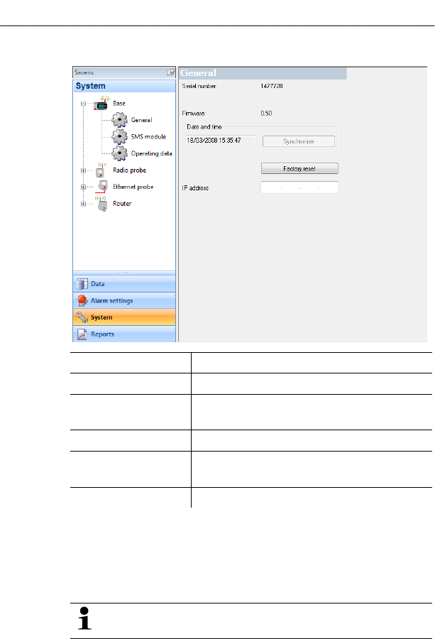
6 Using the product
122 0970 4020 en 01 testo AG
Designation Explanation
Serial number Serial number of the Saveris base.
Firmware Version number of the instrument
software in the Saveris base.
Date and time Date and time of the Saveris base.
[Synchronize] Date and time from the operating system
are applied to the Saveris base.
IP address IP address of the Saveris base.
Pos: 164 /TD/Produkt verwenden/testo Saver is/09 Einstellungen Sy stem/02 SMS-Modul @ 0\m od_1188997905750_79.d oc @ 3811
6.9.2. System settings for the GSM module
Using this menu item, you enter the data of the SIM card and
can determine whether the alarm messages are to be sent
again if the first attempt at sending them should fail.
To be able to use the notification function via SMS you
require a Saveris base with an integrated GSM module.
1. Open the Base entry.
- The submenu items General, SMS module and Operating
data are shown under the entry.
2. Click on SMS module to open the settings for sending the
SMS messages.
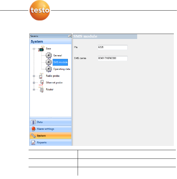
6 Using the product
0970 4020 en 01 123
- The settings are shown in the display range.
Designation Explanation
PIN PIN number of SIM card.
SMS centre Number of the message centre.
Pos: 165 /TD/Produkt verwenden/testo Saver is/09 Einstellungen Sy stem/03 Betriebsda ten @ 1\mod_1197536994375 _79.doc @ 6253
6.9.3. Show operating data of the probes.
Using this menu item, you can check when the last data were
received from a probe, for example, and the duration until the
next readings can be expected.
1. Open the Base entry.
- The submenu items General, SMS module and Operating
data are shown under the entry.
2. Click on Operating data to look at the connection data.
- The connection data are listed in the display range
according to probe.
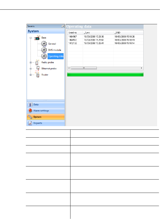
6 Using the product
124 0970 4020 en 01 testo AG
Designation Explanation
Serial no. Serial number of the probe
_Sync Date and time of the last connection.
_SND Date and time when the probe last sent
data.
_RCV Date and time when the probe last
received data.
_next Sync Date and time of the next planned
connection establishment.
_Starttime Date and time of the first measurement of
the probe.
_Values within
[min]
Duration in minutes until the probe
delivers the next data.
Pos: 166 /TD/Produkt verwenden/testo Saver is/09 Einstellungen Sy stem/03 Wireless probe s @ 0\mod_1189598701 171_79.doc @ 4463
6.9.4. Settings for the radio probe
Using this menu item you can, for example, check the battery
status of the probe or the quality of the radio transmission.
1. Open the Radio probe entry.
- The radio probes connected in the Saveris base are listed
under the entry.
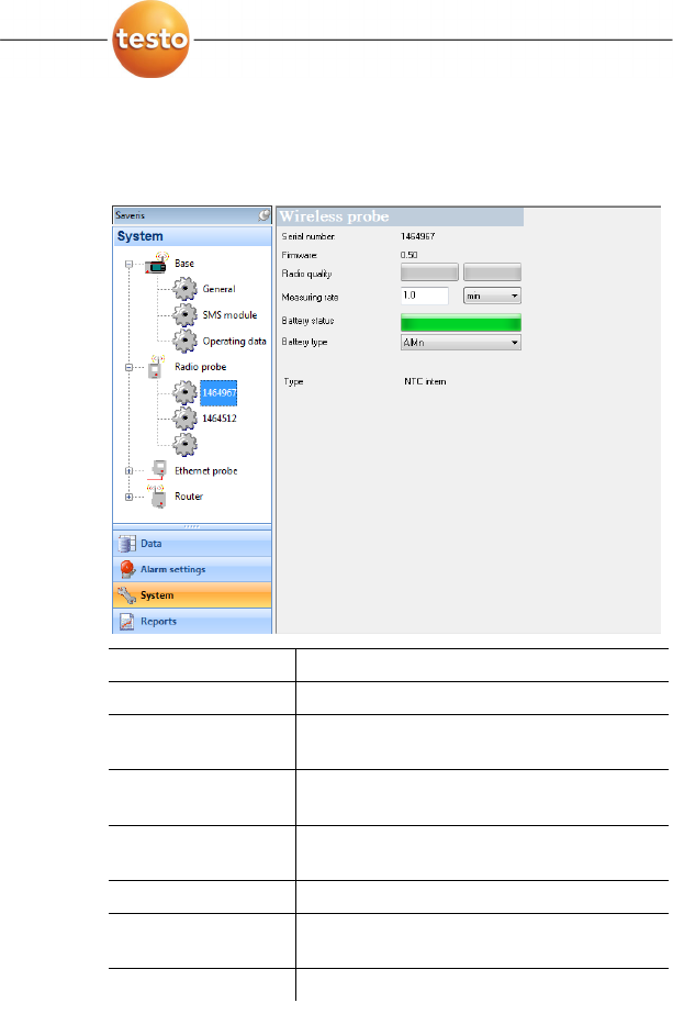
6 Using the product
0970 4020 en 01 125
2. Click on one of the probe names to open the information on
the probe.
- The settings of the selected radio probe are shown in the
display range.
Designation Explanation
Serial number Serial number of the probe.
Firmware Version number of the probe's instrument
software.
Radio quality Field strength of the last radio link to the
Saveris base.
Meas. cycle Interval in which the measurements
should be performed.
Battery status Charge level of the batteries in the probe.
Battery type Selection list for specifying the battery
type (AlMn or Energizer)
Type Specification of the probe type.
Pos: 167 /TD/Produkt verwenden/testo Saver is/09 Einstellungen Sy stem/04 Ethernet prob es @ 0\mod_1190896768531_ 79.doc @ 5172
6.9.5. Ethernet probes
Using this menu item, you can, for example, check the version
of the instrument software or the IP address of an Ethernet
probe.
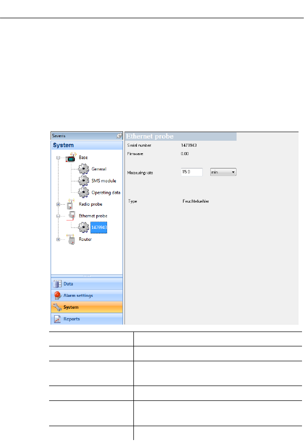
6 Using the product
126 0970 4020 en 01 testo AG
1. Open the Ethernet probe entry.
- The Ethernet probes connected to the Saveris base are
shown under the entry.
2. Click on one of the probe names to open the information on
the probe.
- The settings of the selected probe are shown in the display
range.
Designation Explanation
Serial number Serial number of the probe.
Firmware Version number of the probe's instrument
software.
IP address IP address of the probe.
Meas. cycle Interval in which the measurements
should be performed.
Type Specification of the probe type.
Pos: 168 /TD/Produkt verwenden/testo Saver is/09 Einstellungen Sy stem/05 Router @ 1\ mod_1197537685343_79.d oc @ 6263
6.9.6. Router
Using this menu item, assign which radio probes should transfer
their measurement data to the Saveris base via a router.
1. Open the Router entry.
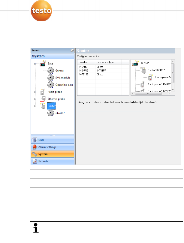
6 Using the product
0970 4020 en 01 127
- Under the entry the routers connected at the Saveris base
are shown and the radio probes connected at the base are
listed in the display range.
Designation Explanation
Serial no. Serial number of the radio probe.
Connection type Specification as to whether the radio
probe has a Direct connection to the
Saveris base or if a router transmits the
readings (display of the router serial
number).
The structure overview shows you which radio probes
are directly connected to the Saveris base and which
are integrated into the measuring system via a router.
2. Click in the connection type cell of the probe which is to be
assigned to a router.
- The cell is shown as a selection list.
Pos: 169 /TD/Produkt verwenden/testo Saver is/10 Einstellungen Ber ichte/00 Einste llungen Berichte @ 0\mod_118 9494078218_79.doc @ 4243
6.10. Report settings
In the report settings, you can determine how the automatic
reporting should take place.
1. Click on Reports in the navigation area.
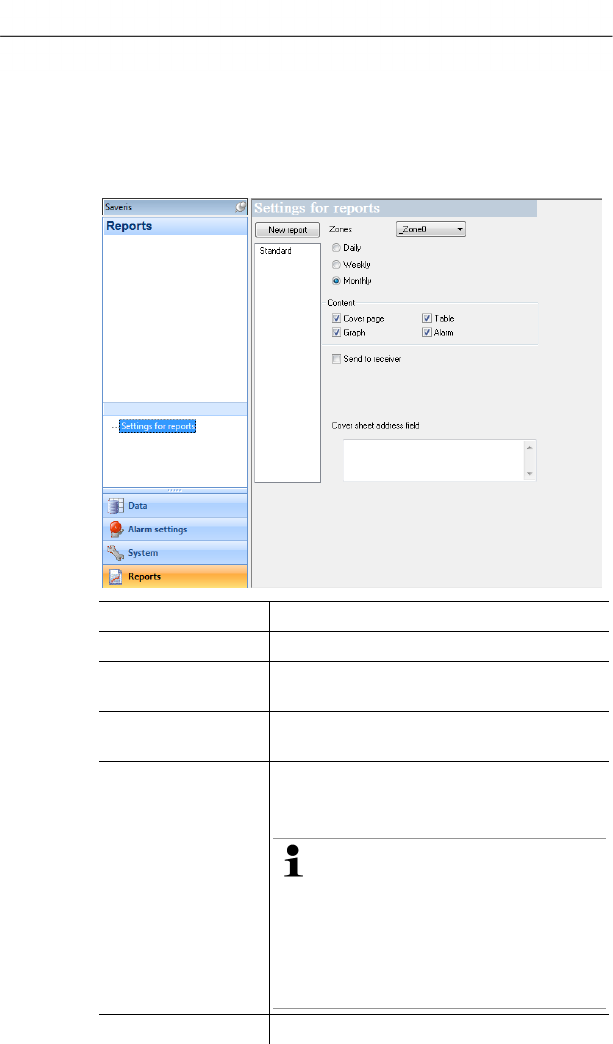
6 Using the product
128 0970 4020 en 01 testo AG
- The
Settings for reports submenu is shown in the data
window.
2. Click on Settings for reports.
- The report settings are shown in the display range.
Pos: 170 /TD/Produkt verwenden/testo Saver is/10 Einstellungen Ber ichte/01 Settings @ 0\mod_1188997925140 _79.doc @ 3821
Designation Explanation
[New report] Adds a new reporting task to the list.
List of the reporting
tasks
List of the created reporting tasks.
Zones Selection list of the group for which the
report should be created.
Time of the creation Specification as to whether the report
should be created Daily, Weekly or
Monthly.
Daily: The report is created daily
at 12 a.m.
Weekly: The report is created
every Sunday at 12 a.m.
Monthly: The report is created on
the last day of the month at 12
a.m.
Content group field With activated option the corresponding

6 Using the product
0970 4020 en 01 129
Designation Explanation
• Cover page
• Graph
• Table
• Alarms
data sheet is attached to the report.
Send to receiver
option
Specification as to whether the report
should be sent to an employee by e-mail.
If the function is activated, the input fields
for the recipient address and the subject
line as well as the [Address book] button
are shown.
Recipient input field Input field for the e-mail address of the
employee to whom the report is to be
sent.
[Address book] Opens the dialogue for the selection of
the recipient from the Outlook contact list.
Subject Input field for the subject line.
Data sheet
address field
Input field for the address that should be
shown on the pages of the report.
The storage location for the reports was determined
during the installation of the Saveris software. Generally
this is C:\Documents and Settings\All
Users\Documents\Saveris Small Business Edition.
Pos: 171 /TD/--- Seitenwechsel --- @ 0\mod_117 3774430601_0.doc @ 283
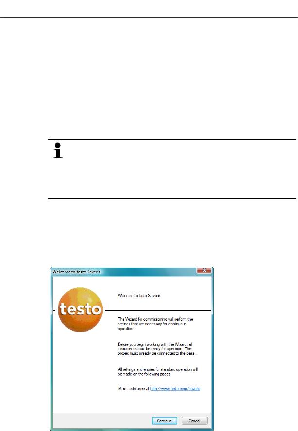
7 Maintaining the product
130 0970 4020 en 01 testo AG
Pos: 172 /TD/Überschr iften/7. Produkt i nstand halten @ 0\mod_117378 9831362_79.doc @ 397
7 Maintaining the product
Pos: 173 /TD/Produkt ins tand halten/test o Saveris/00 Ersatz von Ko mponenten @ 0\mod_1188476 464890_79.doc @ 2909
7.1. Replacement of components
You can shut down a component – probe, converter or router –
at any time because this is temporarily not in use or to replace it
with a new component, for example, in the event of a defect.
In the event of a replacement of the Saveris base, you
must reinstall the software and set up the entire
measurement system again.
Remember to save the existing measurement data
before reinstalling the software.
Pos: 174 /TD/Produkt ins tand halten/test o Saveris/01 Komponenten en tfernen @ 0\mod_11937 37448921_79.doc @ 5643
7.1.1. Deleting components
1. Under Start | All Programs | Testo click on Saveris
Startup Assistant.
- The welcome dialogue of the startup assistant is shown.
2. Click on [Continue >].
- The
System status dialogue with the General tab is shown.
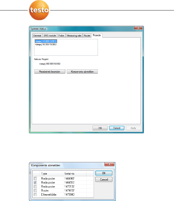
7 Maintaining the product
0970 4020 en 01 131
3. Change to Projects tab.
4. Click on [Log out component].
- The
Log out component dialogue is shown.
5. Activate the checkbox in front of the component that is to be
logged out of the system.
6. Click on [OK].
- A query to erase the components from the configuration is
shown.
7. Confirm the query with [Yes].
- The component is deleted from the configuration.
> After deleting a probe, briefly press the connect button on
the rear of the probe so that the probe no longer attempts to
send measurement data.
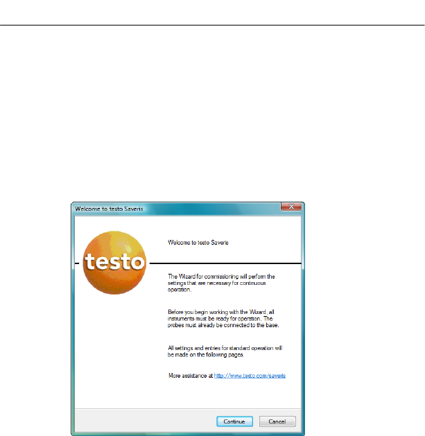
7 Maintaining the product
132 0970 4020 en 01 testo AG
Pos: 175 /TD/Produkt ins tand halten/test o Saveris/02 Komponenten hi nzufügen @ 0\mod_1188 476503984_79.doc @ 2918
7.1.2. Adding components
1. Connecting new probes at the Saveris base; see
"Connecting radio probe".
2. Start up testo Saveris software.
- The software recognizes that a new probe is located in the
system and the wizard for the installation of a new
component is started.
3. Click on [Continue >].
- The Commission new probe dialogue is shown.
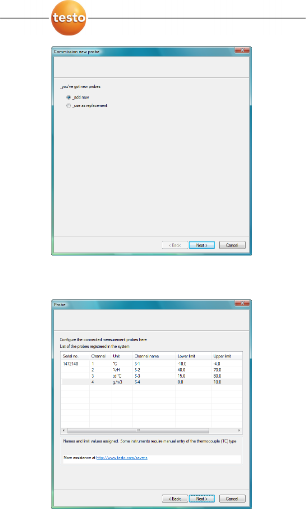
7 Maintaining the product
0970 4020 en 01 133
4. Leave default setting and click on [Continue >].
- The list of the probes newly registered in the Saveris base is
shown.

7 Maintaining the product
134 0970 4020 en 01 testo AG
The fields of the Channel name column for probe
designations are required fields. You must fill in these
fields to be able to continue with the startup.
The Lower limit and Upper limit fields are already
preassigned limit values, but you can adapt the limit
values to your requirements.
The limit values determine as of which reading the
Saveris base triggers an alarm.
5. Click in the Channel name field and enter the designation
of the probe, e.g. "Room 4".
> Click in the Lower limit field and change the lower limit
value.
If all probes are to have the same limit value, click on
the column title with the right mouse button and then
click on Apply to all in the context menu. This also
applies for the upper limit value in the next step.
> Click in the Upper limit field and change the upper limit
value.
> Click in the TC type field and enter the type of thermocouple
if this information is required for the instrument.
> Perform step 4 and the following for all other new probes
until all required fields are filled.
6. Click on [Continue >].
- The settings for measuring cycle, the alarm delay and the
alarm issue are shown.
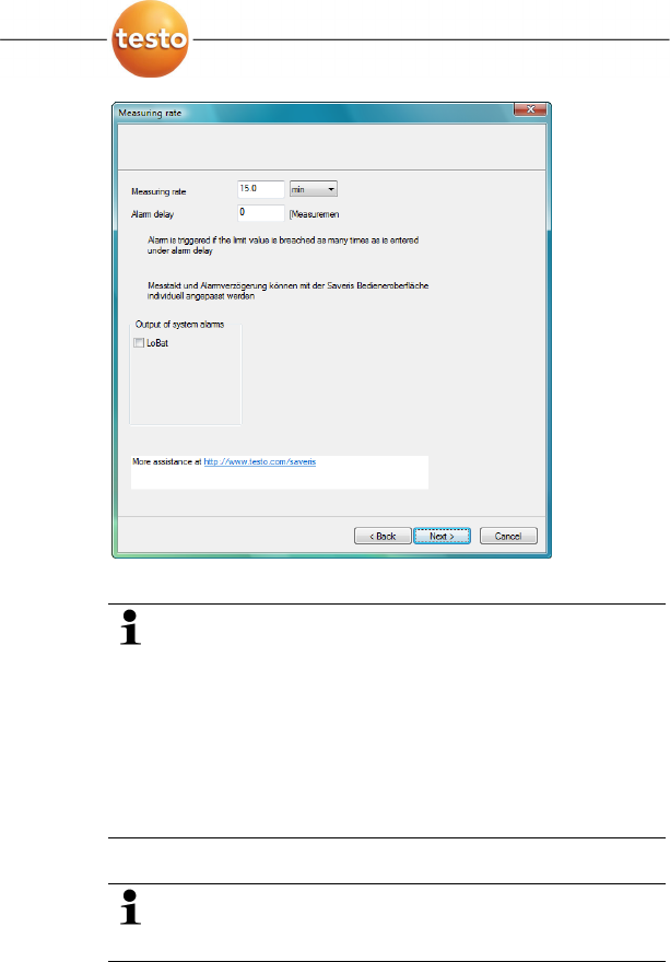
7 Maintaining the product
0970 4020 en 01 135
7. Enter the Measuring cycle and determine its Unit.
The measuring cycle determines in which intervals a
new reading is saved in the Saveris base.
Possible settings for the unit:
• sec (second)
• min (minute)
• h (hour).
The smallest transfer rate for radio probes is one
minute.
8. Determine Alarm delay.
If you enter the value "5" for example, an alarm is not
triggered by the Saveris base until the fifth time that the
limit value is exceeded.
9. Determine in which cases a system alarm should be
triggered.
10. Click on [Continue >].
- If a router is connected at the Saveris base the configuration
of the connection type for the probes is shown.
If no router is connected continue with step 15.
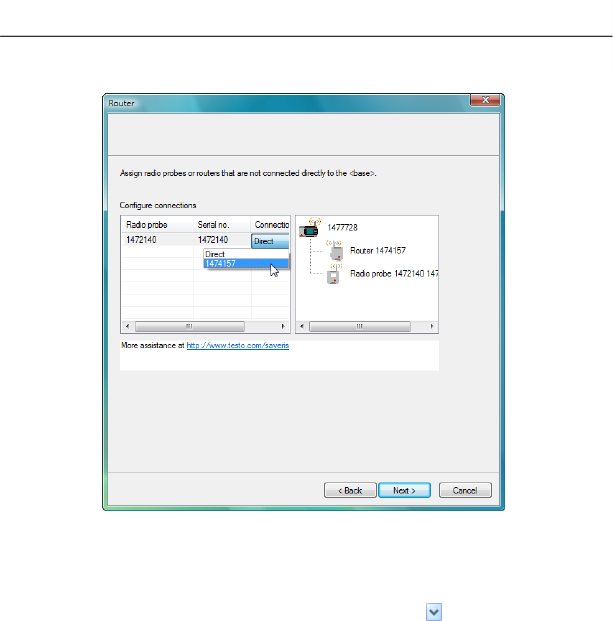
7 Maintaining the product
136 0970 4020 en 01 testo AG
11. Click in the Connection type cell of the probe which is to be
assigned to a router.
- The cell is shown as a selection list.
12. Open the selection list via the button and select the router
to which the probe is to be assigned.
13. Perform steps 11 and 12 for all remaining probes whose
measurement data is to be transmitted to the Saveris base
via a router.
14. Click on [Continue >].
- The wizard is shown with the setting for the start of
measurement and the list of the newly registered probes.
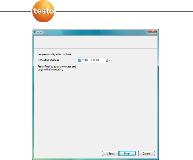
7 Maintaining the product
0970 4020 en 01 137
15. Postpone the start of measurement, if necessary.
16. Click on [Finish] to complete the startup of the hardware.
- A note on the successful configuration of the hardware is
shown.
17. Press [OK] to confirm the note.
- The new hardware is now ready for operation.
Pos: 176 /TD/Produkt ins tand halten/test o Saveris/Kalibrier ung und Justage @ 0\mod_118 8476360640_79.doc @ 2882
7.2. Calibration and adjustment
All testo Saveris probes are adjusted in the factory, which is
confirmed by the corresponding adjustment report.
You can undertake other calibrations or adjustments on site.
The separate Saveris adjustment software is available for this.
After successful adjustment, the current adjustment data is
stored in the probe. At the same time, the adjustment software
and the Saveris software accept this data so that the
adjustment histories are available.
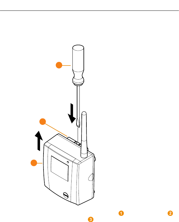
7 Maintaining the product
138 0970 4020 en 01 testo AG
Pos: 177 /TD/Produkt ins tand halten/test o Saveris/Fühler von W andhalterung abnehmen @ 0\mod_11 91328027078_79.doc @ 5382
7.3. Removing probe from wall bracket
1. Using a narrow flat tip screwdriver release the probe
from the wall bracket .
2. Remove probe from wall bracket towards top, as shown.
Pos: 178 /TD/Produkt ins tand halten/test o Saveris/Batterien a m Fühler wechseln @ 0\mod_118 8476555656_79.doc @ 2927
1
2
3
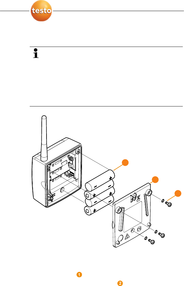
7 Maintaining the product
0970 4020 en 01 139
7.4. Changing batteries at probe
The batteries have a life of
• 3 years with standard AlMn batteries at +25 °C and
• 3 years with Energyzer L91 Photo lithium batteries
for freezer applications.
You can check the battery status of the probes via the
Saveris software. To do so, select the probe that you
wish to check under System | Radio probe. In the
Battery status field, the current charge state is shown.
> Remove probe from the wall bracket; see "Removing probe
from wall bracket".
1. Loosen screws on the rear of the probe.
2. Remove housing cover of probe .
1
2
3
7 Maintaining the product
140 0970 4020 en 01 testo AG
3. Change batteries .
Ensure that you insert the batteries correctly.
The correct polarity is illustrated in the respective
battery compartment.
4. Place housing cover on probe housing.
5. Screw cover down close to the housing.
A control switch is located in the housing that is
actuated through the cover. To do so, the cover must be
screwed to the probe housing without a gap.
If the control switch is not actuated through the cover,
the probe cannot be operated.
Caution! Unintended residual discharge when
disposing of old batteries.
> Mask the poles of the old batteries in order to
prevent an unintended residual discharge by means
of short-circuits during disposal.
Pos: 179 /TD/--- Seitenwechsel --- @ 0\mod_117 3774430601_0.doc @ 283

7 Maintaining the product
0970 4020 en 01 141
Pos: 180 /TD/Überschr iften/3.2 Technisc he Daten @ 0\mod_11762110884 37_79.doc @ 704
7.5. Technical data
Pos: 181 /TD/Leistungs beschreibung/Tec hnische Daten/tes to Saveris/01 Basissta tion @ 0\mod_1191323639 453_79.doc @ 5302
7.5.1. Saveris base
Characteristic Values
Memory 40,000 values per channel (total max.
10,160,000 values)
Dimensions 225 x 150 x 49 mm
Weight approx. 1510 g
Protection class IP42
Housing material Die-cast zinc/plastic
Radio frequency 868 MHz/2.4 GHz
Power supply 6.3 V DC mains unit; alternatively via
24 V AC/DC plug-in/screw terminals,
power consumption < 4 W.
Rech. batt. Li-ion battery
The rechargeable battery is used only for
backing up data and for emergency SMS
in the event of failure of the power supply,
not for the power supply during operation.
Operating
temperature
-10 to +50 °C
Storage
temperature
-40 to +85 °C
Display Graphical LCD display
Interfaces USB, radio, Ethernet
Number of radio
probes
max. 15 probes can be directly connected
via radio interface,
max. 150 total via radio/router/converter
and Ethernet,
max. 254 channels.
Alarm relay max. 1 A, max. 30 W, max. 60/25 V
DC/AC, NC or NO contact
GSM module 850/900/1800/1900 MHz
Installation Table base and wall bracket included

7 Maintaining the product
142 0970 4020 en 01 testo AG
Pos: 182 /TD/Leistungs beschreibung/Techni sche Daten/testo Sa veris/05 Fühler @ 0\ mod_1191323803625_79.d oc @ 5342
7.5.2. Saveris radio probe
General
The technical data listed in the following table are valid for all
Saveris radio probes. Special data for the individual probe types
can be found in the following sections.
Characteristic Values
Housing dimensions
(W x H x D)
80 x 85 x 38 mm
Length of antenna 81 mm
Weight approx. 240 g
Battery type 4 AA mignon batteries
Battery life 3 years at +25 °C
3 years with Energyzer L91 Photo lithium
batteries for freezer applications
Housing material Plastic
Radio frequency 868 MHz/2.4 GHz
Meas. cycle Standard 15 min (can be set from 1 min
up to 24 h)
Storage
temperature
-40 to +55 °C
Display (optional) 2-line LCD; 7 segments with symbols
Transmission
distance
approx. 300 m free field at 868 MHz,
approx. 100 m free field at 2.4 GHz
Wall bracket included
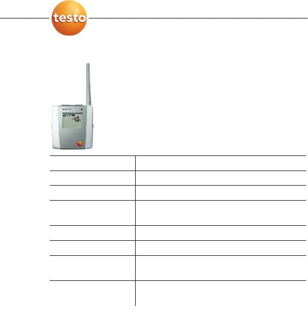
7 Maintaining the product
0970 4020 en 01 143
Saveris T1/T1D radio probe
Characteristic Values
Probe type NTC
Measuring range -35 to +50 °C
Accuracy ±0.4 °C (-25 to +50 °C)
±0.8 °C (rest of measuring range)
Resolution 0.1 °C
Protection class IP68
Conformity with
standards
DIN EN 12830
Operating
temperature
-35 to +50 °C
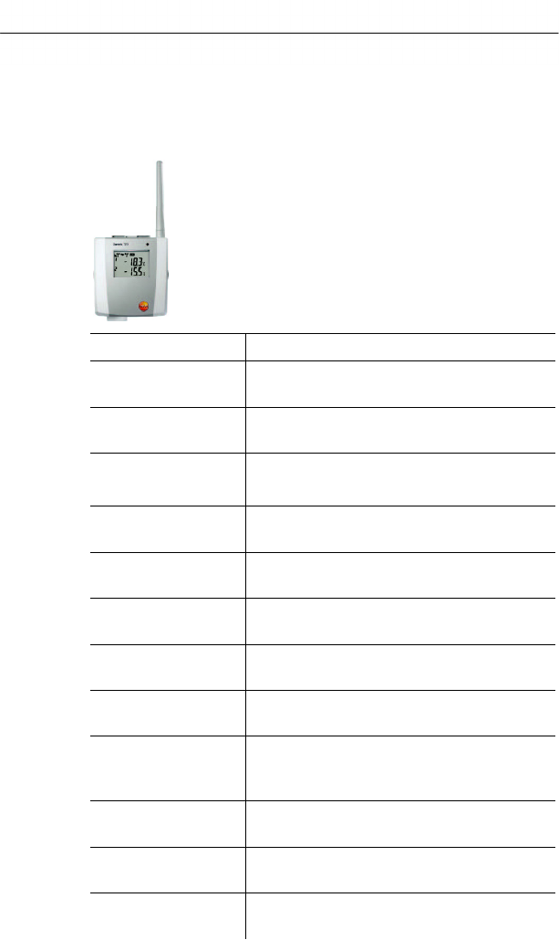
7 Maintaining the product
144 0970 4020 en 01 testo AG
Saveris T2/T2D radio probe
Radio probe with external probe connection and internal NTC,
door contact
Characteristic Values
Probe type
(internal)
NTC
Measuring range
(internal)
-35 to +50 °C
Accuracy
(internal)
±0.4 °C (-25 to +50 °C)
±0.8 °C (rest of measuring range)
Resolution
(internal)
0.1 °C
Probe type
(external)
NTC
Measuring range
(external)
-50 to +150 °C
Accuracy
(external)
±0.2 °C (-25 to +70 °C)
±0.4 °C (rest of measuring range)
Resolution
(external)
0.1 °C
Connection NTC via mini-DIN socket, door contact
connection cable included in delivery
(1.80 m)
Protection class IP68 (with probe inserted or port sealed
with rubber plug)
Conformity with
standards
DIN EN 12830
Operating
temperature
-35 to +50 °C
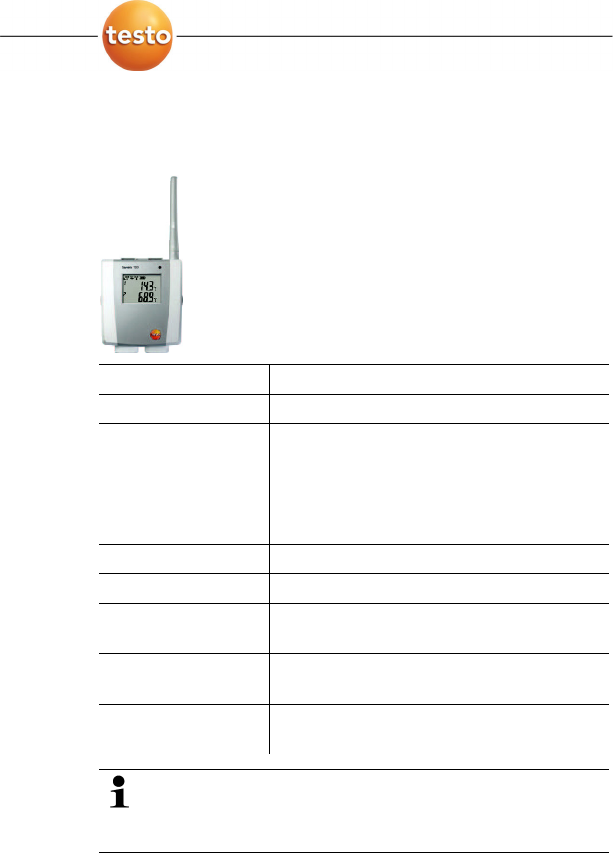
7 Maintaining the product
0970 4020 en 01 145
Saveris T3/T3D radio probe
2-channel radio probe with 2 external TC probe connections
(TC characteristics can be selected)
Characteristic Values
Probe type TC
Measuring range
TC type J
TC type K
TC type S
TC type T
-100 to +750 °C
-195 to +1350 °C
0 to +1760 °C
-200 to +400 °C
Accuracy ±0.5 °C or 0.5 % of measured value
Resolution 0.1 °C/TC type S 1 °C
Connection 2 TCs via TC socket,
max. difference in potential 2 V
Protection class IP54 (with probe inserted or port sealed
with rubber plug)
Operating
temperature
-20 to +50 °C
The probe inputs are not isolated from one another.
Take this into account when using probes with non-
isolated thermocouple.
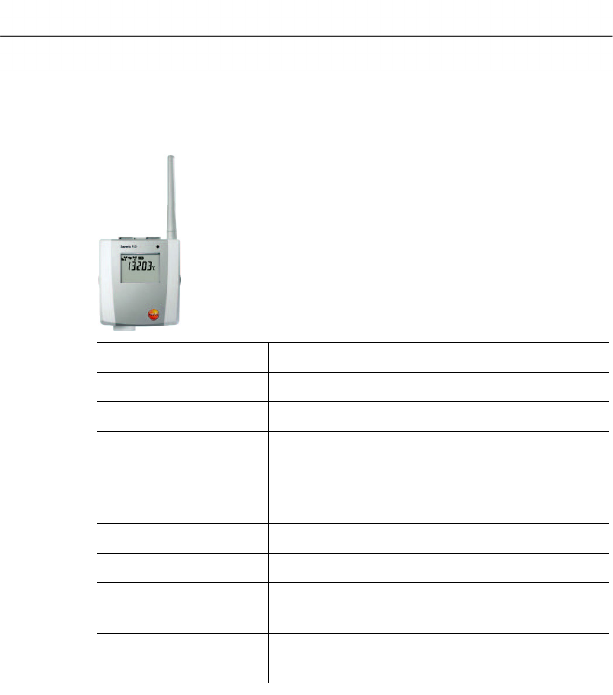
7 Maintaining the product
146 0970 4020 en 01 testo AG
Saveris Pt/PtD radio probe
Radio probe with an external Pt100 probe connection
Characteristic Values
Probe type Pt100
Measuring range -200 to +600 °C
Accuracy ±0.1 °C (0 to +60 °C)
±0.2 °C (-100 to +200 °C)
±0.5 °C (rest of measuring range)
at 25 °C
Resolution 0.01 °C
Connection 1 Pt100 via mini-DIN socket
Protection class IP68 (with probe inserted or port sealed
with rubber plug)
Operating
temperature
-20 to +50 °C
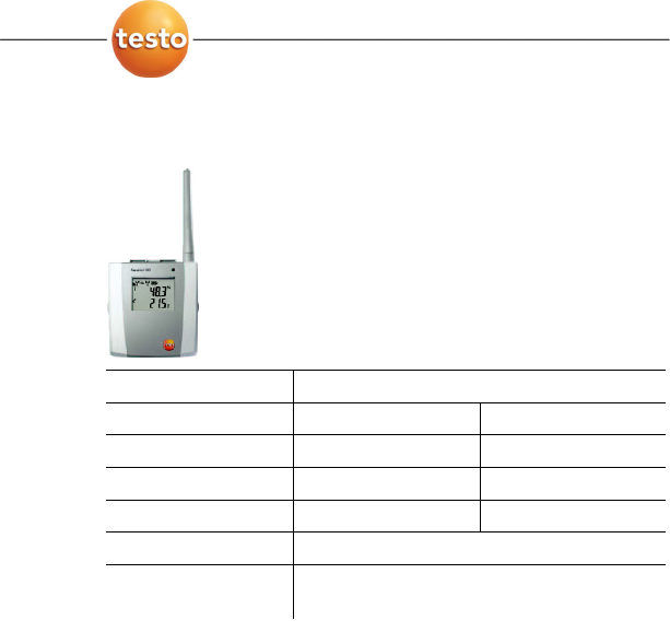
7 Maintaining the product
0970 4020 en 01 147
Saveris H3/H3D radio probe
Humidity radio probe
Characteristic Values
Probe type NTC Humidity sensor
Measuring range -20 to +50 °C 0 to 100 % RH
Accuracy ±0.5 °C ±3 % RH
Resolution 0.1 °C/0.1 °Ctd 0.1 %
Protection class IP 42
Operating
temperature
-20 to +50 °C
Pos: 183 /TD/Leistungs beschreibung/Techni sche Daten/testo Sa veris/04 Router @ 0\mo d_1191323737875_79.doc @ 5332

7 Maintaining the product
148 0970 4020 en 01 testo AG
7.5.3. Saveris router
Characteristic Values
Housing dimensions
(W x H x D)
80 x 100 x 38 mm
Length of antenna 81 mm
Weight approx. 180 g
Power supply 6.3 V DC mains unit;
alternatively via 24 V AC/DC plug-
in/screw terminals,
power consumption < 5 W
Housing material Plastic
Protection class IP54
Operating
temperature
-20 to +50 °C
Storage
temperature
-40 to +85 °C
Interfaces Radio
Number of radio
probes
max. 5
Wall bracket included
Pos: 184 /TD/Leistungs beschreibung/Techni sche Daten/testo Sa veris/06 Ethernet- Fühler @ 1\mod_1197559409 437_79.doc @ 6435
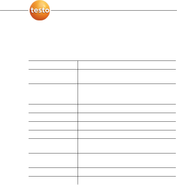
7 Maintaining the product
0970 4020 en 01 149
7.5.4. Saveris Ethernet probes
The technical data listed in the following table are valid for all
Saveris Ethernet probes. Special data for the individual probe
types can be found in the following sections.
Characteristic Values
Housing dimensions
(W x H x D)
85 x 100 x 38 mm
Power supply 6.3 V DC mains unit;
alternatively via 24 V AC/DC plug-
in/screw terminals
Buffer battery Li-ion
Housing material Plastic
Protection class IP54
Meas. cycle 2 sec - 24 h
Operating
temperature
-20 to +70 °C
Storage
temperature
-40 to +85 °C
Display (optional) 2-line LCD; 7 segments with symbols
Wall bracket included
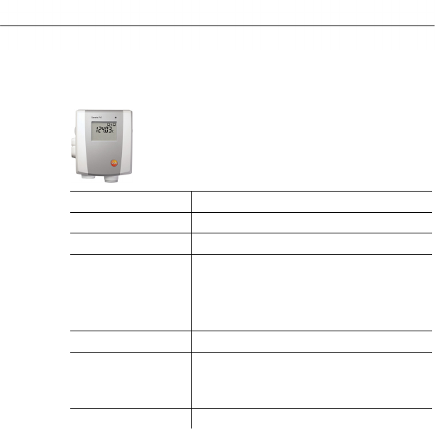
7 Maintaining the product
150 0970 4020 en 01 testo AG
Saveris PtE Ethernet probe
Ethernet probe with external Pt100 probe connection
Characteristic Values
Probe type Pt100
Measuring range -200 to +600 °C
Accuracy ±0.1 °C (0 to +60 °C)
±0.2 °C (-100 to +200 °C)
±0.5 °C (rest of measuring range)
at 25 °C
Resolution 0.01 °C
Connection Mini-DIN service interface is accessible
externally
1 Pt100 via mini-DIN socket
Weight approx. 220 g
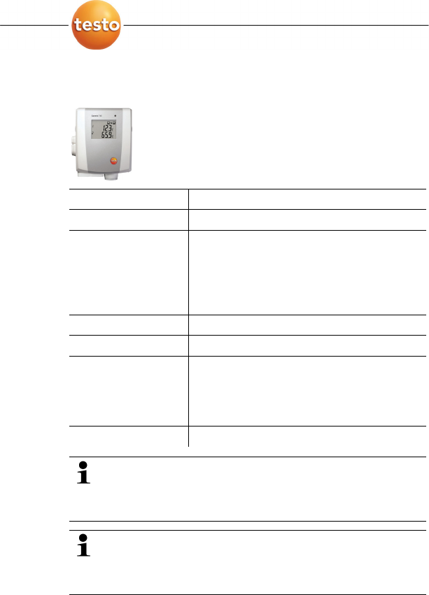
7 Maintaining the product
0970 4020 en 01 151
Saveris T4E Ethernet probe
4-channel Ethernet probe with 4 external TC probe connections
Characteristic Values
Probe type TC
Measuring range
TC type S
TC type T
TC type J
TC type K
0 to +1760 °C
-200 to +400 °C
-100 to +750 °C
-195 to +1350 °C
Accuracy ±0.5 °C or 0.5 % of measured value
Resolution 0.1 °C/TC type S 1 °C
Connection Mini-DIN service interface is accessible
externally
4 TCs via TC socket
max. difference in potential 50 V
Weight approx. 220 g
The technical data refer to the probe in a stable,
stationary operating mode. To receive a stable
measurement the probe must be in operation for one to
two hours.
The usage of isolate thermocouples is recommended
for supplying the Ethernet probe. Otherwise
discrepancies in readings of up to 0.6 °C may occur due
to leakage currents.
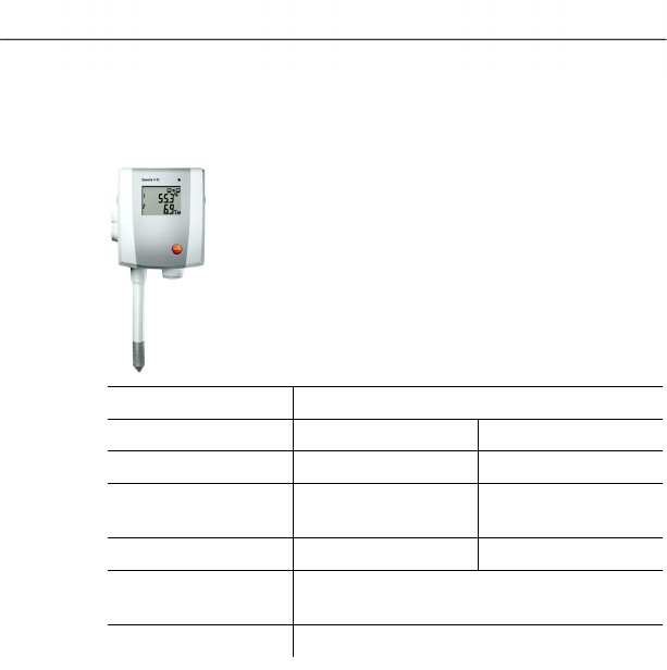
7 Maintaining the product
152 0970 4020 en 01 testo AG
H2E Ethernet probe
Humidity Ethernet probe, 2 %
Characteristic Values
Probe type Humidity sensor NTC
Measuring range 0 to 100 % RH* -20 to +70 °C
Accuracy ±2 % RH < 90 % RH
±3 % RH > 90 % RH
±0.5 °C
Resolution 0.1 %/0.1 °Ctd 0.1 %
Connection Mini-DIN service interface is accessible
externally
Weight approx. 230 g
* not for continuous high-humidity applications
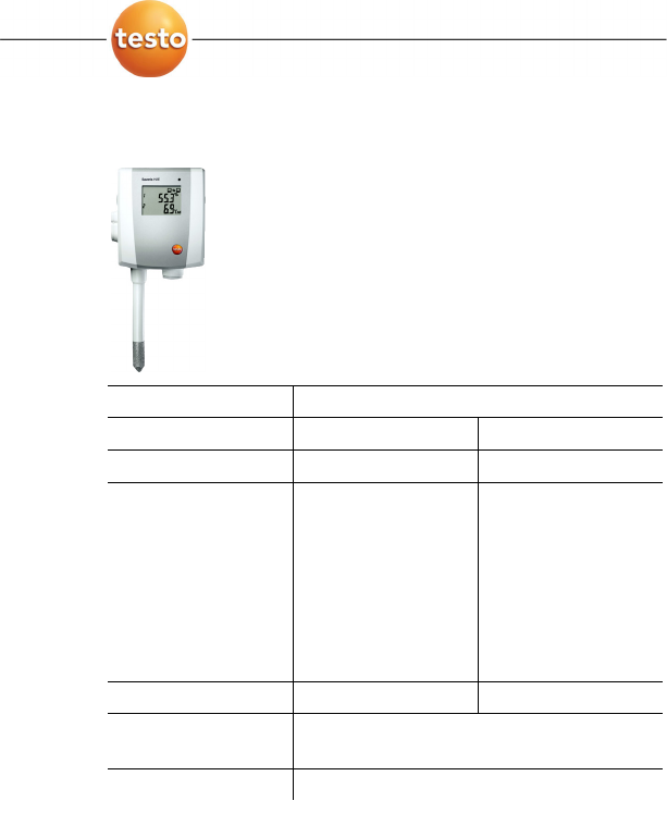
7 Maintaining the product
0970 4020 en 01 153
H1E Ethernet probes
Humidity Ethernet probe, 1 %
Characteristic Values
Probe type Humidity sensor NTC
Measuring range 0 to 100 % RH* -20 to +70 °C
Accuracy ±(1 % RH + 0.7 % of
meas. value)
< 90 % RH
at 25 °C
±(1.4 % RH + 0.7 %
of meas. value)
> 90 % RH
at 25 °C
±0.2 °C
(0 to +30 °C)
±0.5 °C (rest of
measuring range)
Resolution 0.1 %/0.1 °Ctd 0.1 %
Connection Mini-DIN service interface is accessible
externally
Weight approx. 230 g
* not for continuous high-humidity applications
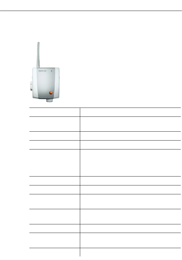
7 Maintaining the product
154 0970 4020 en 01 testo AG
Pos: 185 /TD/Leistungs beschreibung/Techni sche Daten/testo Sa veris/04-2 Con verter @ 1\mod_1196955545798 _79.doc @ 6063
7.5.5. Saveris converter
Characteristic Values
Housing dimensions
(W x H x D)
80 x 100 x 35 mm
Length of antenna 81 mm
Weight approx. 190 g
Power supply 6.3 V DC mains unit;
alternatively via 24 V AC/DC plug-
in/screw terminals,
power consumption < 2 W
Housing material Plastic
Protection class IP54
Operating
temperature
-20 to +50 °C
Storage
temperature
-40 to +85 °C
Interfaces Radio, Ethernet
Number of radio
probes
max. 15
Wall bracket included
Pos: 186 /TD/--- Seitenwechsel --- @ 0\mod_117 3774430601_0.doc @ 283

8 Tips and assistance
0970 4020 en 01 155
Pos: 187 /TD/Überschr iften/8. Tipps und Hilfe @ 0\mod_117378988798 5_79.doc @ 406
8 Tips and assistance
Pos: 188 /TD/Überschr iften/8.1 Fragen und Ant worten @ 0\mod_11774020 17078_79.doc @ 1093
8.1. Questions and answers
Pos: 189 /TD/Tipps und Hilfe/Fragen und Antworte n/testo Saveris/FA Q Probleme und Lösungen @ 0\ mod_1188479044703_79. doc @ 3046
1. After changing the batteries, I no long receive values
from my probe and the LED on the front does not light
up.
• Check whether the housing cover is bolted down
correctly.
• Check the batteries with an appropriate measuring
instrument and if necessary exchange these if they are
not OK.
• Briefly press the button on the rear of the probe and the
LED must show the radio quality; see "

8 Tips and assistance
156 0970 4020 en 01 testo AG
Meaning of the LED displays at the probes".
If this is not the case and the probe flashes red, the
configuration of the probe is faulty. Reconnect the probe
and reconfigure it.
2. Only the battery symbol and the symbol of the radio
quality appear on the display of my probe.
The probe has not yet received a valid configuration.
Connect the probe to the base and execute the startup
assistant.
3. Despite the proper connection of a probe, I do not
receive readings after the probe was placed at its
location.
Press the button on the rear of the probe. If the LED on the
front flashes red, the probe is outside of the radio range.
• Install a router in the system and assign the probe to the
router using the startup assistant (see "Integrating
Saveris router (optional)") or
• Place the probe at a suitable location so that the probe is
within the radio range.

8 Tips and assistance
0970 4020 en 01 157
4. A probe is too far away from the Saveris base. Even
integrating a router was unsuccessful. Can I connect
multiple routers in series to extend the radio range?
No, connecting multiple routers in series is not possible. To
bridge the transmission path, you have the option of using a
router and a converter and creating the connection from the
converter to the Saveris base using an Ethernet cable.
5. Can the data transfer from the radio probes to the base
be influenced by other instruments communicating by
radio?
A disruption of the transfer by other radio subscribers that
operate with the same radio frequency as the Saveris
system is not impossible. However, routines were
implemented in the Saveris system that prevent the loss of
data. The data are transferred via an intelligent protocol that
can head off faults or only transfers data when the radio
frequency is free.
6. What must I take into account when placing the
individual components?
The local conditions must be taken into account for the
placement. The radio is obstructed by objects such as thick
walls made of reinforced concrete, metal doors etc.
You can seek out suitable locations using a radio probe.
Briefly press the button on the rear of the probe to show the
current radio quality by means of the LED; see "

8 Tips and assistance
158 0970 4020 en 01 testo AG
Meaning of the LED displays at the probes".
If you are outside of the range the LED lights up red. You
can then create or optimize the transmission path with a
router connected between the Saveris base and the probe.
Rough advanced planning using a floor plan of the building
has proved itself worthwhile.
7. The Saveris base shows an incorrect date and an
incorrect time. How can this be set?
You can synchronize the date and time when starting up the
hardware or within the Saveris software, meaning applying
the date and time from the operating system of the
computer; see "Starting up hardware" and "General settings
for the Saveris base".
The changeover between winter/summer time is made
automatically.
8. How long may the USB cable between the base and the
computer be?
The USB cable for connecting the Saveris base to the
computer may be a maximum of 5 m.
9. Why is a bidirectional radio used with testo Saveris?
Only by using a bidirectional radio (i.e. probes and Saveris
base are both transmitters and receivers) is it possible to
ensure that the data communication between the
participants can be performed without loss of data.
10. After the configuration of the probes and the base the
software was started, but no probes or readings are
shown.
For the initial start of the Saveris software after starting up
the system, it takes approx. 15 to 60 minutes until the first
readings from the system are entered in the database. The
probes and their readings are only visible in the software
when the data are present in the database.
11. The base was connected to a USB port of the computer
but is not automatically recognized by this.
Download the current USB driver for the Saveris system
from the Testo website (www.testo.com/saveris) and install
the new driver.
The Saveris base may not be connected to the computer
during the installation of the driver. After restarting the

8 Tips and assistance
0970 4020 en 01 159
computer, the Saveris base can be reconnected with the
computer and should then be automatically recognized.
12. How can I change the language for the user guidance at
the Saveris base?
Disconnect the mains plug of the Saveris base and wait
about one minute. After connecting the mains plug, the base
shows the language selection. Select the new language and
press [Enter] at the Saveris base. The base starts up with
the new language setting.
13. After commissioning a probe the reading is outside of
the limit values, but no alarm was triggered by the
Saveris base.
The readings that are recorded from the probe must have
already been within the limit values for a breach of the limit
values to be recognized by the Saveris base.
Pos: 190 /TD/Überschr iften/8.2 Zubehör und Er satzteile @ 0\mod_11774 02058734_79.doc @ 1102
8.2. Accessories and spare parts
Pos: 191 /TD/Tipps und Hilfe/Zubehör und Ersa tzteile/testo Saveri s @ 0\mod_1188805346875_7 9.doc @ 3193
Description Article no.
Spare batteries for radio probes
(4 x AA alkali manganese mignon
batteries)
0515 0414
Spare batteries for radio probes for
operation below -10 °C
(Energyzer L91 Photo lithium)
0515 0572
Mains unit 100 to 200 V DC; for Saveris
base, router, converter, Ethernet probe
0554 1096
Mains unit (top-hat rail mounting) 90 to
240 VAC/24 VDC (2.5 A)
0554 1749
Mains unit (desktop instrument) 90 to
240 VAC/24 VDC (350 mA)
0554 1745
Antenna with magnetic base with 3 m
cable for base with GSM module
0554 0524
Quad-band antenna 0554 0525
Alarm module (optical & acoustic), can be
connected to alarm relay, Ø 700 x 164
mm, 24 V AC/DC/320 mA, steady on: red,
steady tone: buzzer approx. 2.4 kHz
0629 6666

8 Tips and assistance
160 0970 4020 en 01 testo AG
Description Article no.
testo Saveris SBE software, incl. USB
cable for connection of the Saveris base
to the computer
0572 0180
testo Saveris PROF software, incl. USB
cable for connection of the Saveris base
to the computer
0572 0181
Saveris adjustment software 0572 0183
Measurement data view via Internet on request
ISO temperature calibration certificate;
temperature data logger;
calibration points -18 °C, 0 °C, +60 °C;
per channel/instrument
0520 0151
DKD temperature calibration certificate;
temperature data logger;
calibration points -20 °C, 0 °C, +60 °C;
per channel/instrument
0520 0261
ISO humidity calibration certificate;
humidity data logger;
calibration points 11.3 % RH and 75.3 %
RH at +25 °C; per channel/instrument
0520 0076
DKD humidity calibration certificate;
humidity data logger;
calibration points 11.3 % RH and 75.3 %
RH at +25 °C; per channel/instrument
0520 0246
===== Ende der Stücklist e =====

testo AG
Postfach 1140, 79849 Lenzkirch
Testo-Strasse 1, 79853 Lenzkirch
GERMANY
Phone: +49 (0) 7653 681-0
Fax: +49 (0) 7653 681-100
Internet: www.testo.com
email : info@testo.com
Handling codes :
Document code:
0970 4020 en 01