Texas Instruments S4110R S4110 MFR Based Reader Evaluation Kit User Manual
Texas Instruments Inc S4110 MFR Based Reader Evaluation Kit Users Manual
Users Manual
TI PROPRIETARY T E X A S I N S T R U M E N T S Originator
:
INFORMATION - C. Bohren
INTERNAL DATA R F I D SYSTEMS
S P E C I F I C A T I O N
Revision: 00
User Guide Test Control Software
S4110 MFR Evaluation Kit Page 1 of 15 XX-XX-XX-XXX
Subco/Mfg Spec.
User Guide Test Control Software
S4110 MFR Evaluation Kit
PRINTED COPIES OF THIS SPECIFICATION
ARE NOT CONTROLLED DOCUMENTS.
VERIFY THEIR CORRECT REVISION BEFORE USE.

TI PROPRIETARY T E X A S I N S T R U M E N T S
INFORMATION - Revision:
INTERNAL DATA R F I D SYSTEMS 00
S P E C I F I C A T I O N
User Guide Test Control Software
S4110 MFR Evaluation Kit Page 2 of 15 XX-XX-XX-XXX
Printed copies are not controlled documents - verify the correct revision before use.
TABLE OF CONTENTS PAGE
1. Purpose..............................................................................................................3
2. Hardware Set up...............................................................................................3
2.1 S4110 MFR Evaluation Kit Hardware supplied...........................................3
2.2 Hardware Set Up.........................................................................................4
3. Test Software ....................................................................................................5
3.1 Initial Start Screen ......................................................................................5
3.2 Connection to RS232 Communications (Com) Port.....................................5
3.2.1 Communications Port Choices.............................................................5
3.3 Turn On HF Transmitter .............................................................................6
3.4 Turn On LF Transmitter..............................................................................8
3.5 Turn Off HF Transmitter...........................................................................10
3.6 Turn Off LF Transmitter ...........................................................................11
3.7 Close Com Port.........................................................................................12
3.8 Close Application .....................................................................................13
4. Installation Guide S4110R MFR Evaluation Kits as shipped from factory .13
4.1 Box Unit S4110 MFR Evaluation Kit as shipped from factory ..................14
4.1.1 Placement of FCC Label on Box Unit ...............................................14
4.2 SDK Unit S4110 MFR Evaluation Kit as shipped from factory.................14
4.2.1 Placement of FCC Label on Box Unit ...............................................14
5. Revision History..............................................................................................15
LIST OF FIGURES
Figure 1: Back Panel MFR Evaluation Kit Black Box Reader.............................. 3
Figure 2: Software Development Kit (SDK)........................................................... 3
Figure 3: Globtek Power Supply Model Number: GT-21089-1509-T3................. 4
Figure 4: Hardware Set Up MFR Evaluation Kit.................................................. 4
Figure 5: Initial Start Screen .................................................................................. 5
Figure 6: Com Port Choices supported.................................................................. 6
Figure 7: Successful “Com” Port Connection........................................................ 7
Figure 8: Turn On HF Transmitter........................................................................ 7
Figure 9: Successful "Turn On " of HF Transmitter ............................................ 8
Figure 10: Turn On LF Transmitter ...................................................................... 9
Figure 11: Successful “Turn On” of LF Transmitter ............................................ 9
Figure 12: Turn Off HF Transmitter ....................................................................10
Figure 13: Turn Off LF Transmitter....................................................................11
Figure 14: Com Port Closure.................................................................................12
Figure 15: Successful Com Port Closure...............................................................13
Figure 16: FCC Label for S4110R MFR Evaluation Kit......................................13
Figure 17: Placement of FCC Label on S4110R Evaluation Kit Box Unit...........14
Figure 18: Placement of FCC Label on S4110R Evaluation Kit SDK Unit .........14
TI PROPRIETARY T E X A S I N S T R U M E N T S
INFORMATION - Revision:
INTERNAL DATA R F I D SYSTEMS 00
S P E C I F I C A T I O N
User Guide Test Control Software
S4110 MFR Evaluation Kit Page 3 of 15 XX-XX-XX-XXX
Printed copies are not controlled documents - verify the correct revision before use.
1. Purpose
The purpose of this document is to demonstrate the Test Control software for
the S4110 MFR Evaluation Kit..
2. Hardware Set up
2.1 S4110 MFR Evaluation Kit Hardware supplied
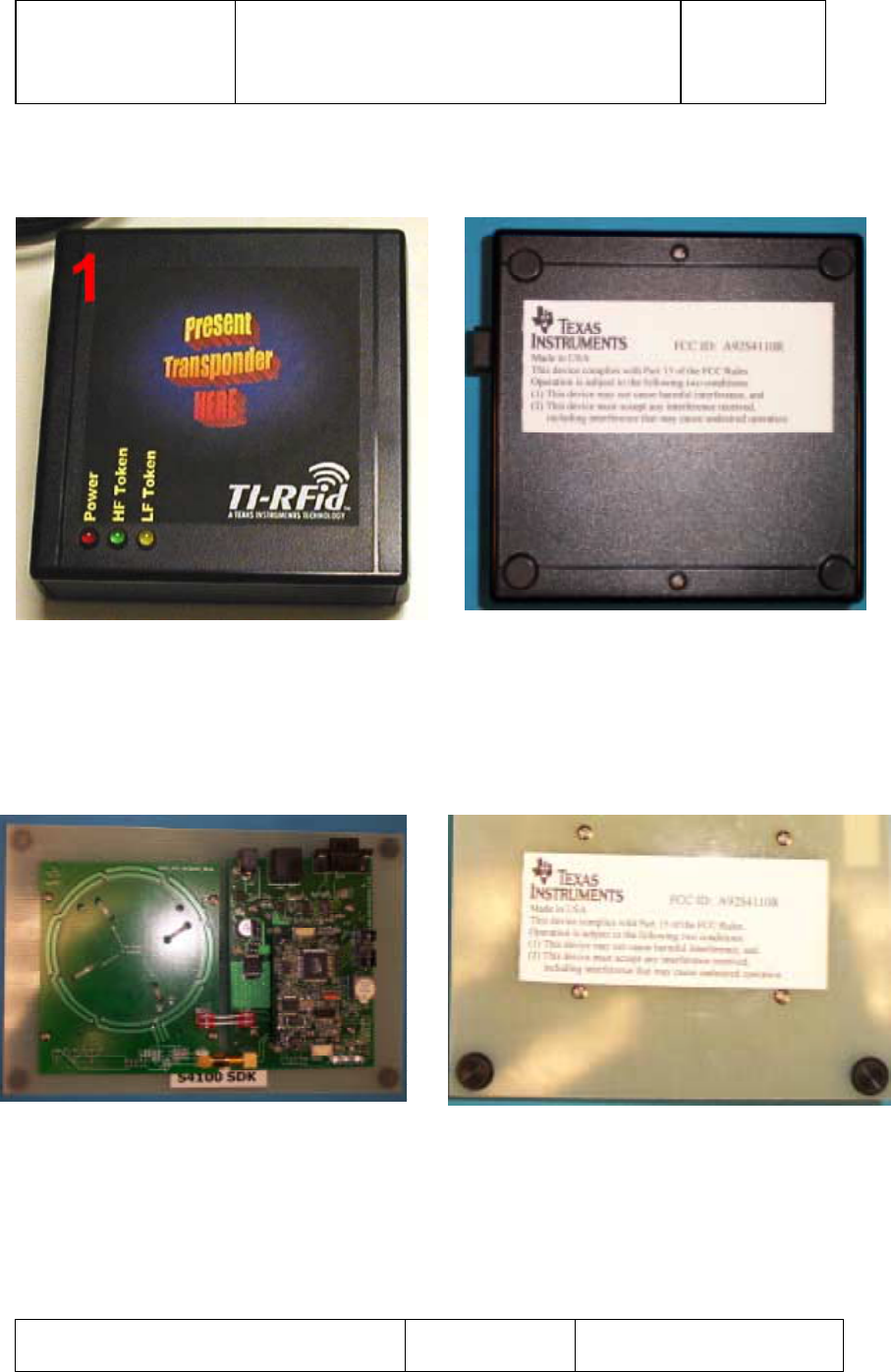
1) S4110 MFR Evaluation Kit Black Box Reader
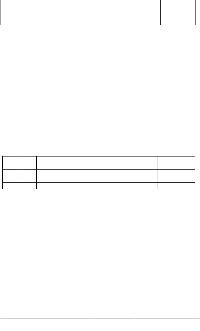
2) S4110 MFR Evaluation Kit Software Development Kit (SDK) Reader
3) Power Supply, 9.0 Vdc 1.0 A, Globtek Part Number: TR9CD1700LCP-Y
Globtek Model Number: GT-21089-1509-T3
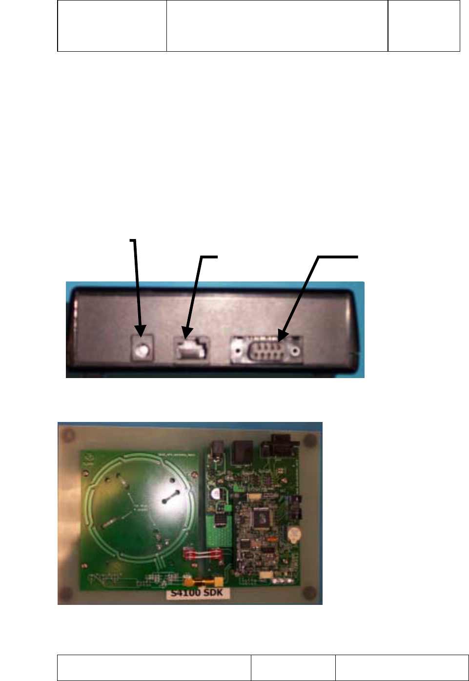
Figure 1: Back Panel MFR Evaluation Kit Black Box Reader
Figure 2: Software Development Kit (SDK)
DC Power connector
+9 Vdc is center pin RS485 Connector RS232 Connector
TI PROPRIETARY T E X A S I N S T R U M E N T S
INFORMATION - Revision:
INTERNAL DATA R F I D SYSTEMS 00
S P E C I F I C A T I O N
User Guide Test Control Software
S4110 MFR Evaluation Kit Page 4 of 15 XX-XX-XX-XXX
Printed copies are not controlled documents - verify the correct revision before use.
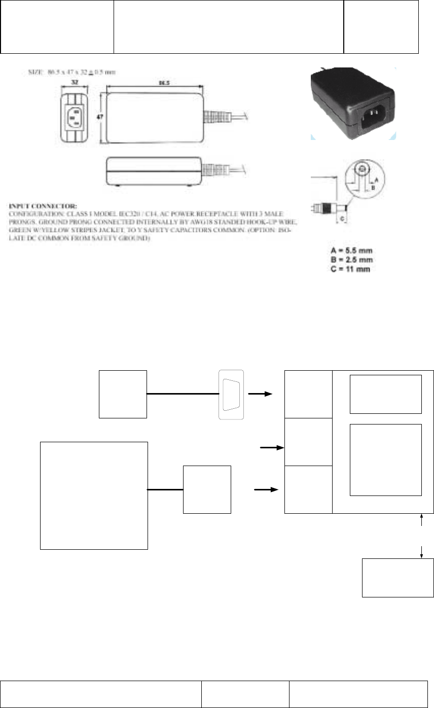
Figure 3: Globtek Power Supply Model Number: GT-21089-1509-T3
Globtek Part Number: TR9CD1700CP-Y
2.2 Hardware Set Up
RS232
RS485
+9 Volts
DC
Power
Communications
board Connector
J232
RS232
J485
RS485
J12
Power
Connector, DB9M
PC with
MFR Eval
Kit
Test
Software
PC Com 1
Serial RS232
Port
No Connection
Power Supply
9V DC 1.0 Amp
Globtek PN: TR9CD1700CP-Y
Model Number: GT-21089-1509-
T3
Connector
Circular
DIN
S4100 MFR Lite
MFR Evaluation Kit
HF/LF Antenna
Board
TAG
D = Distance form Tag to Reader "D
"
Figure 4: Hardware Set Up MFR Evaluation Kit
TI PROPRIETARY T E X A S I N S T R U M E N T S
INFORMATION - Revision:
INTERNAL DATA R F I D SYSTEMS 00
S P E C I F I C A T I O N
User Guide Test Control Software
S4110 MFR Evaluation Kit Page 5 of 15 XX-XX-XX-XXX
Printed copies are not controlled documents - verify the correct revision before use.
3. Test Software
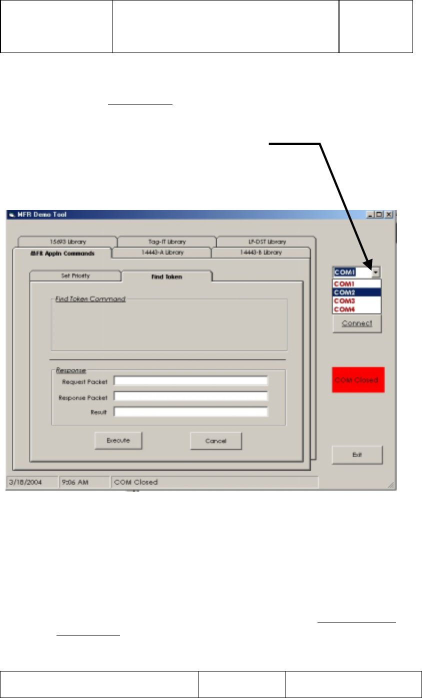
3.1 Initial Start Screen
1) After double clicking the MFR Demo software icon the software screen
below will appear.
2) Double click desired application folder tab to select application.
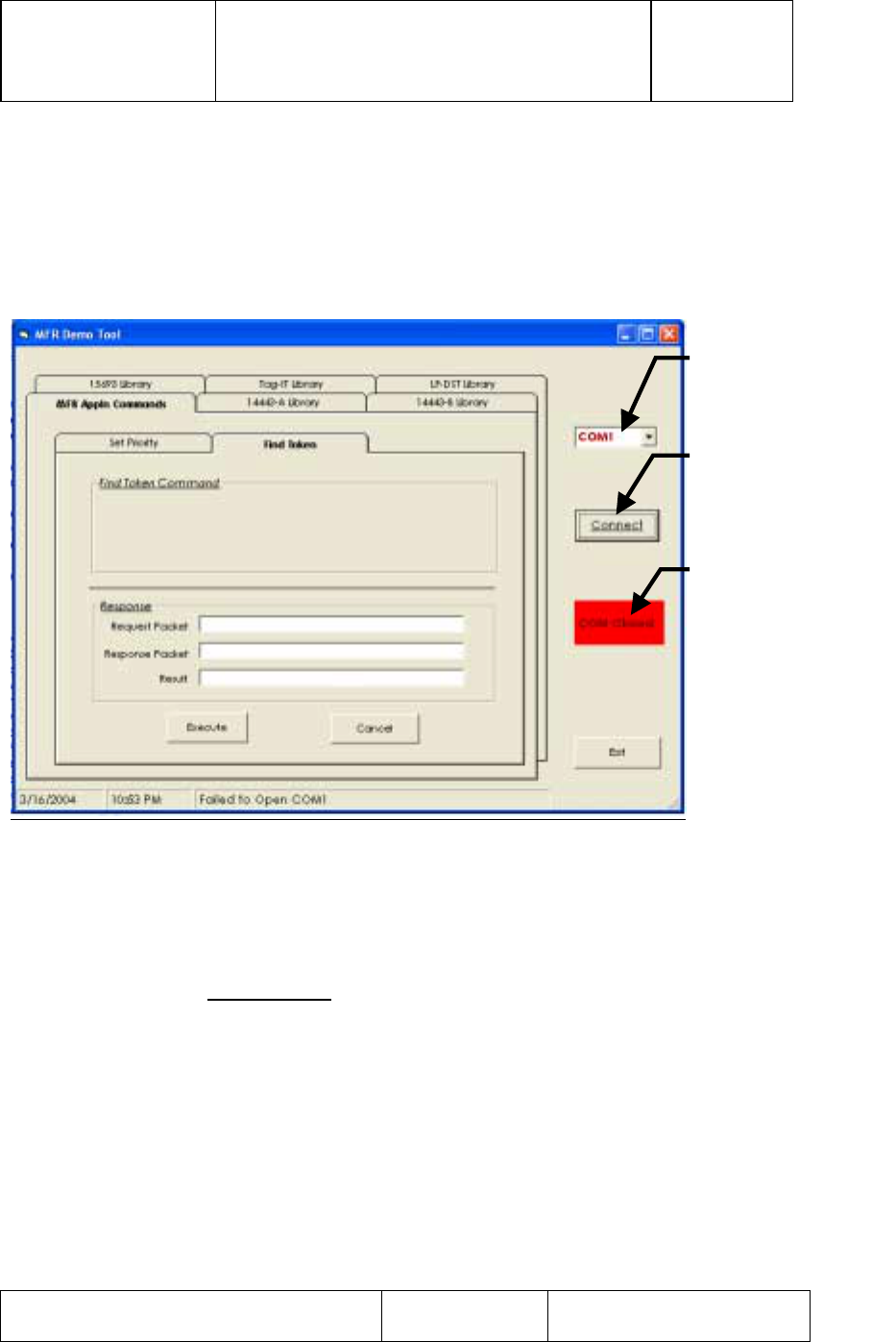
Figure 5: Initial Start Screen
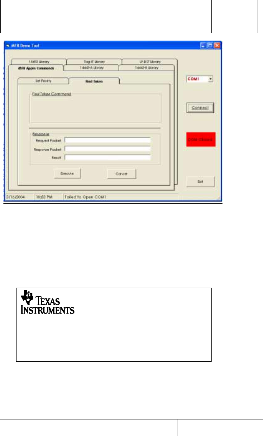
3.2 Connection to RS232 Communications (Com) Port
1) Click on ‘Connect’ button to open the COM port. You’ll see the
red indicator box with ‘COM Closed’ text change color to GREEN
and read ‘COM Opened’ for successful connection.
2) If red indicator box stays red and reads ‘Com Closed’, the COM
port did not open successfully.
3.2.1 Communications Port Choices
1) If the default Com Port of Com1 is not the desired Com Port, use Com
Port selection arrow to select desired Com Port; from the following
choices 1) Com1, 2) Com2, 3) Com3, 4) Com4.
Press to Open
“Com” Port
Selects desired
‘Com’ port
When Status Box
is Green ‘Com’
port is open
TI PROPRIETARY T E X A S I N S T R U M E N T S
INFORMATION - Revision:
INTERNAL DATA R F I D SYSTEMS 00
S P E C I F I C A T I O N
User Guide Test Control Software
S4110 MFR Evaluation Kit Page 6 of 15 XX-XX-XX-XXX
Printed copies are not controlled documents - verify the correct revision before use.
2) Click on ‘Connect’ button to open the COM port. You’ll see the
red indicator box with ‘COM Closed’ text change color to GREEN
and read ‘COM Opened’ for successful connection.
3) If red indicator box stays red and reads ‘Com Closed’, the COM
port did not open successfully.
Figure 6: Com Port Choices supported
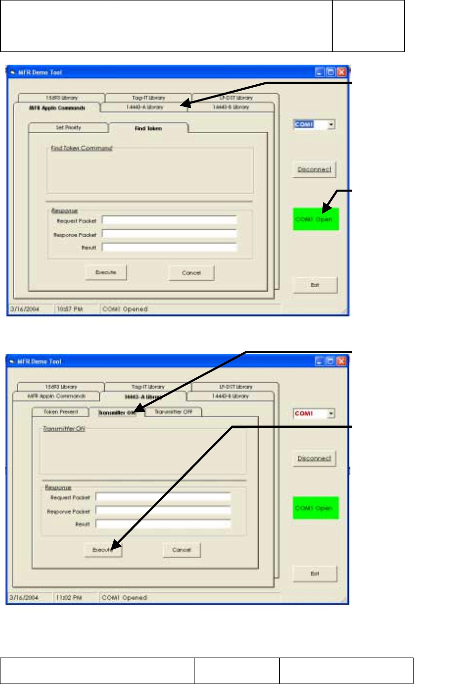
3.3 Turn On HF Transmitter
To Turn on the HF Transmitter:
1) Select 14443A Library folder Tab
2) Under 14443A Library folder Tab select Transmitter On
3) Click on ‘Execute’ button to issue a HF- Transmitter ON Command.
4) If successful, you would see the Green indicator with ‘TRANSMITTER
ON – 14443A’ text.
Use Com Port Selec
t
Arrow to select
desired Com Port
TI PROPRIETARY T E X A S I N S T R U M E N T S
INFORMATION - Revision:
INTERNAL DATA R F I D SYSTEMS 00
S P E C I F I C A T I O N
User Guide Test Control Software
S4110 MFR Evaluation Kit Page 7 of 15 XX-XX-XX-XXX
Printed copies are not controlled documents - verify the correct revision before use.
Figure 7: Successful “Com” Port Connection
Figure 8: Turn On HF Transmitter
When Status Box
is Green ‘Com’
port is open
Select Folder for
14443-A Library to
start HF transmitter
turn on procedure
HF Transmitter
On Folder Tab
Press to turn on
HF (13.56 MHz)
Tran
s
mitt
er
TI PROPRIETARY T E X A S I N S T R U M E N T S
INFORMATION - Revision:
INTERNAL DATA R F I D SYSTEMS 00
S P E C I F I C A T I O N
User Guide Test Control Software
S4110 MFR Evaluation Kit Page 8 of 15 XX-XX-XX-XXX
Printed copies are not controlled documents - verify the correct revision before use.
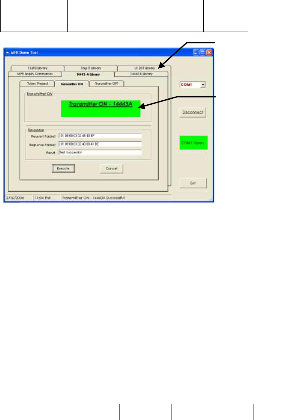
Figure 9: Successful "Turn On " of HF Transmitter
3.4 Turn On LF Transmitter
To Turn on the LF Transmitter:
1) Select LF-DST Library folder Tab
2) Under LF-DST Library folder Tab select Transmitter On
3) Click on ‘Execute’ button to issue a LF- Transmitter ON Command.
4) If successful, you would see the Green indicator with ‘TRANSMITTER
ON – LF-DST’ text.
HF (13.56 MHz)
Transmitter On
Select Folder for
LF-DST Library to
start LF transmitter
turn on procedure
TI PROPRIETARY T E X A S I N S T R U M E N T S
INFORMATION - Revision:
INTERNAL DATA R F I D SYSTEMS 00
S P E C I F I C A T I O N
User Guide Test Control Software
S4110 MFR Evaluation Kit Page 9 of 15 XX-XX-XX-XXX
Printed copies are not controlled documents - verify the correct revision before use.
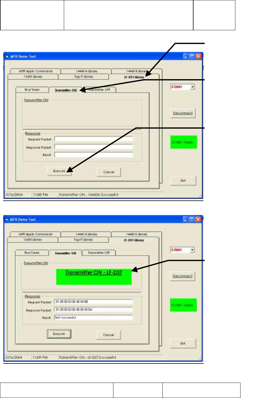
Figure 10: Turn On LF Transmitter
Figure 11: Successful “Turn On” of LF Transmitter
LF Transmitter
On Folder Tab
Press to turn on
LF (134 kHz)
Tran
s
mitt
er
LF (134 kHz)
Transmitter On
Select Folder for
LF-DST Library to
start LF transmitter
turn on procedure
TI PROPRIETARY T E X A S I N S T R U M E N T S
INFORMATION - Revision:
INTERNAL DATA R F I D SYSTEMS 00
S P E C I F I C A T I O N
User Guide Test Control Software
S4110 MFR Evaluation Kit Page 10 of 15 XX-XX-XX-XXX
Printed copies are not controlled documents - verify the correct revision before use.
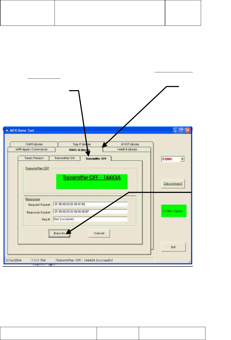
3.5 Turn Off HF Transmitter
To Turn Off the HF Transmitter:
1) Select 14443A Library folder Tab
2) Under 14443A Library folder Tab select Transmitter Off
3) Click on ‘Execute’ button to issue a HF- Transmitter Off Command.
4) If successful, you would see the Green indicator with ‘TRANSMITTER
OFF – 14443A’ text.
Figure 12: Turn Off HF Transmitter
HF Transmitter
Off Folder Tab
Press to turn
off HF
(13.56 MHz)
Transmitte
r
Select Folder for
14443-A Library
to start HF
transmitter turn
off procedure
TI PROPRIETARY T E X A S I N S T R U M E N T S
INFORMATION - Revision:
INTERNAL DATA R F I D SYSTEMS 00
S P E C I F I C A T I O N
User Guide Test Control Software
S4110 MFR Evaluation Kit Page 11 of 15 XX-XX-XX-XXX
Printed copies are not controlled documents - verify the correct revision before use.
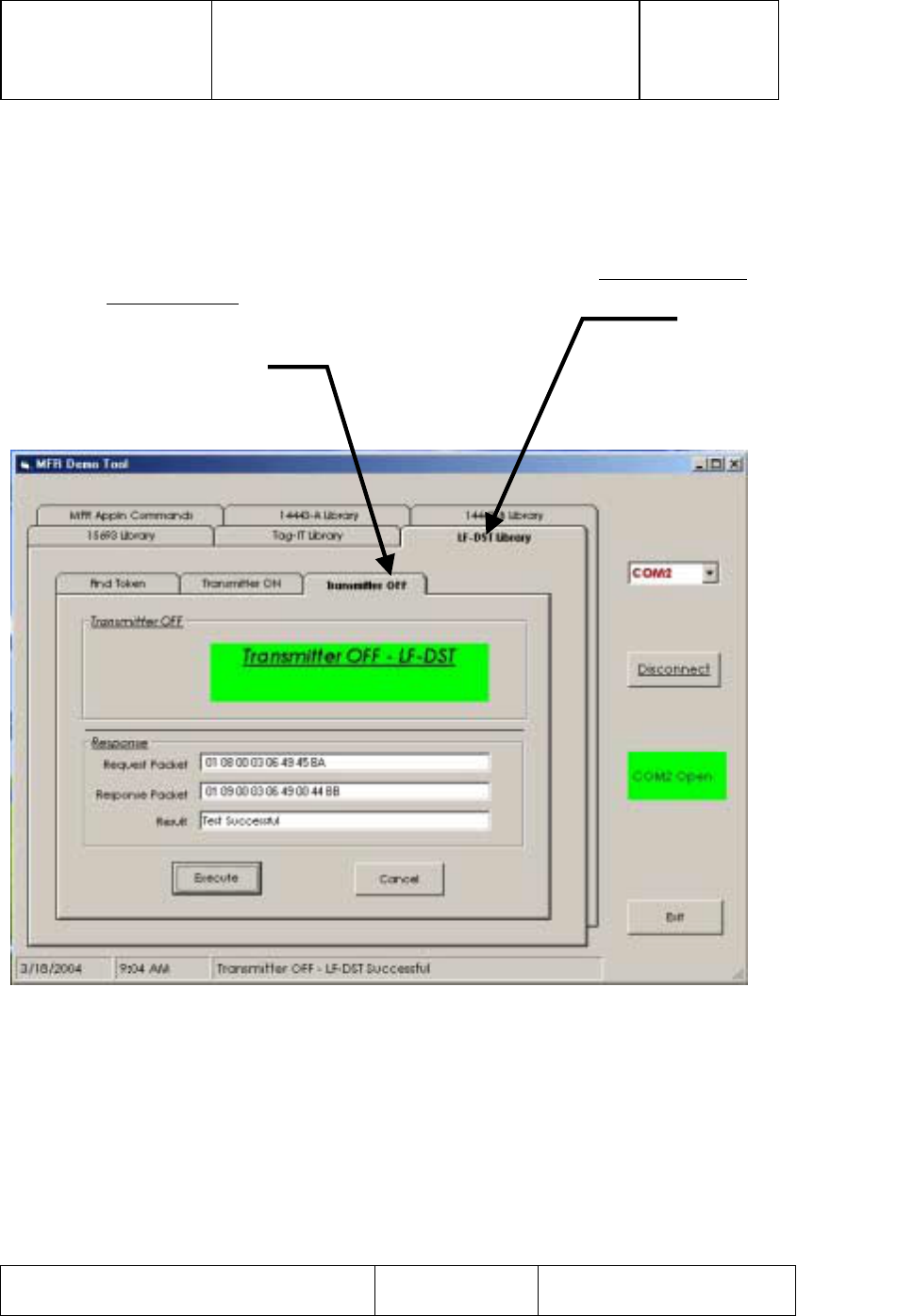
3.6 Turn Off LF Transmitter
To Turn off the LF Transmitter:
1) Select LF-DST Library folder Tab
2) Under LF-DST Library folder Tab select Transmitter OFF
3) Click on ‘Execute’ button to issue a LF- Transmitter OFF Command.
4) If successful, you would see the Green indicator with ‘TRANSMITTER
OFF – LF-DST’ text.
Figure 13: Turn Off LF Transmitter
Select Folder for
LF-DST Library to
start LF transmitter
turn off procedure
LF Transmitter
Off Folder Tab
TI PROPRIETARY T E X A S I N S T R U M E N T S
INFORMATION - Revision:
INTERNAL DATA R F I D SYSTEMS 00
S P E C I F I C A T I O N
User Guide Test Control Software
S4110 MFR Evaluation Kit Page 12 of 15 XX-XX-XX-XXX
Printed copies are not controlled documents - verify the correct revision before use.
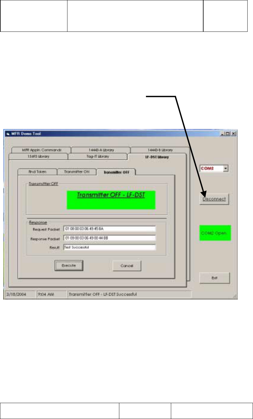
3.7 Close Com Port
1) Close the COM port by clicking on ‘Disconnect’ button.
2) You will see the Green Status Indicator with ‘COM Open’ text,
change color to RED with a text change to ‘Com Closed to indicate
successful closure of the COM port.
Figure 14: Com Port Closure
Press “Disconnect”
Button to Close
‘Com Port’
TI PROPRIETARY T E X A S I N S T R U M E N T S
INFORMATION - Revision:
INTERNAL DATA R F I D SYSTEMS 00
S P E C I F I C A T I O N
User Guide Test Control Software
S4110 MFR Evaluation Kit Page 13 of 15 XX-XX-XX-XXX
Printed copies are not controlled documents - verify the correct revision before use.
Figure 15: Successful Com Port Closure
3.8 Close Application
1) Click EXIT button to close the application.
4. Installation Guide S4110R MFR Evaluation Kits as shipped from factory
The Box unit and SDK unit configurations of the S4110 MFR Evaluation Kit
as shipped from the factory are compliant with FCC Part 15 Rules.
Figure 16: FCC Label for S4110R MFR Evaluation Kit
FCC ID: A92S4110R Made in USA
This device complies with Part 15 of the FCC Rules. Operation is subject to
the following two conditions:
(1) This device may not cause harmful interference, and
(2) This device must accept any interference received, including interference
that may cause undesired operation.
TI PROPRIETARY T E X A S I N S T R U M E N T S
INFORMATION - Revision:
INTERNAL DATA R F I D SYSTEMS 00
S P E C I F I C A T I O N
User Guide Test Control Software
S4110 MFR Evaluation Kit Page 14 of 15 XX-XX-XX-XXX
Printed copies are not controlled documents - verify the correct revision before use.
4.1 Box Unit S4110 MFR Evaluation Kit as shipped from factory
4.1.1 Placement of FCC Label on Box Unit
Figure 17: Placement of FCC Label on S4110R Evaluation Kit Box Unit
4.2 SDK Unit S4110 MFR Evaluation Kit as shipped from factory
4.2.1 Placement of FCC Label on Box Unit
Figure 18: Placement of FCC Label on S4110R Evaluation Kit SDK Unit
TI PROPRIETARY T E X A S I N S T R U M E N T S
INFORMATION - Revision:
INTERNAL DATA R F I D SYSTEMS 00
S P E C I F I C A T I O N
User Guide Test Control Software
S4110 MFR Evaluation Kit Page 15 of 15 XX-XX-XX-XXX
Printed copies are not controlled documents - verify the correct revision before use.
NOTE: This equipment has been tested and found to comply with the limits for a
Class B digital device, pursuant to Part 15 of the FCC Rules. These limits are
designed to provide reasonable protection against harmful interference in a
residential installation. This equipment generates, uses and can radiate radio
frequency energy and, if not installed and used in accordance with the
instructions, may cause harmful interference to radio communications. However,
there is no guarantee that interference will not occur in a particular installation.
If this equipment does cause harmful interference to radio or television reception,
which can be determined by turning the equipment off and on, the user is
encouraged to try to correct the interference by one or more of the following
measures:
-- Reorient or relocate the receiving antenna.
-- Increase the separation between the equipment and receiver.
-- Connect the equipment into an outlet on a circuit different
from that to which the receiver is connected.
-- Consult the dealer or an experienced radio/TV technician for
help.
5. Revision History
Rev. SCN Description of Change Date submitted By
0 New Issue 04/20/2004 C.Bohren