Thales Communications AHV1600 Radio-altimeter Transceiver User Manual OIM AHV1600 REV01
THALES Communications Radio-altimeter Transceiver OIM AHV1600 REV01
UserManual.wiki
>
Thales Communications
>
AHV1600 User Manual
>
USER MANUAL REV1
Contents
1.
OIM
2.
Users Manual
3.
USER MANUAL REV1
USER MANUAL REV1
Navigation menu
Upload a User Manual
Namespaces
Wiki Guide
HTML
PDF
Info
Views
User Manual
Discussion / Help
Navigation


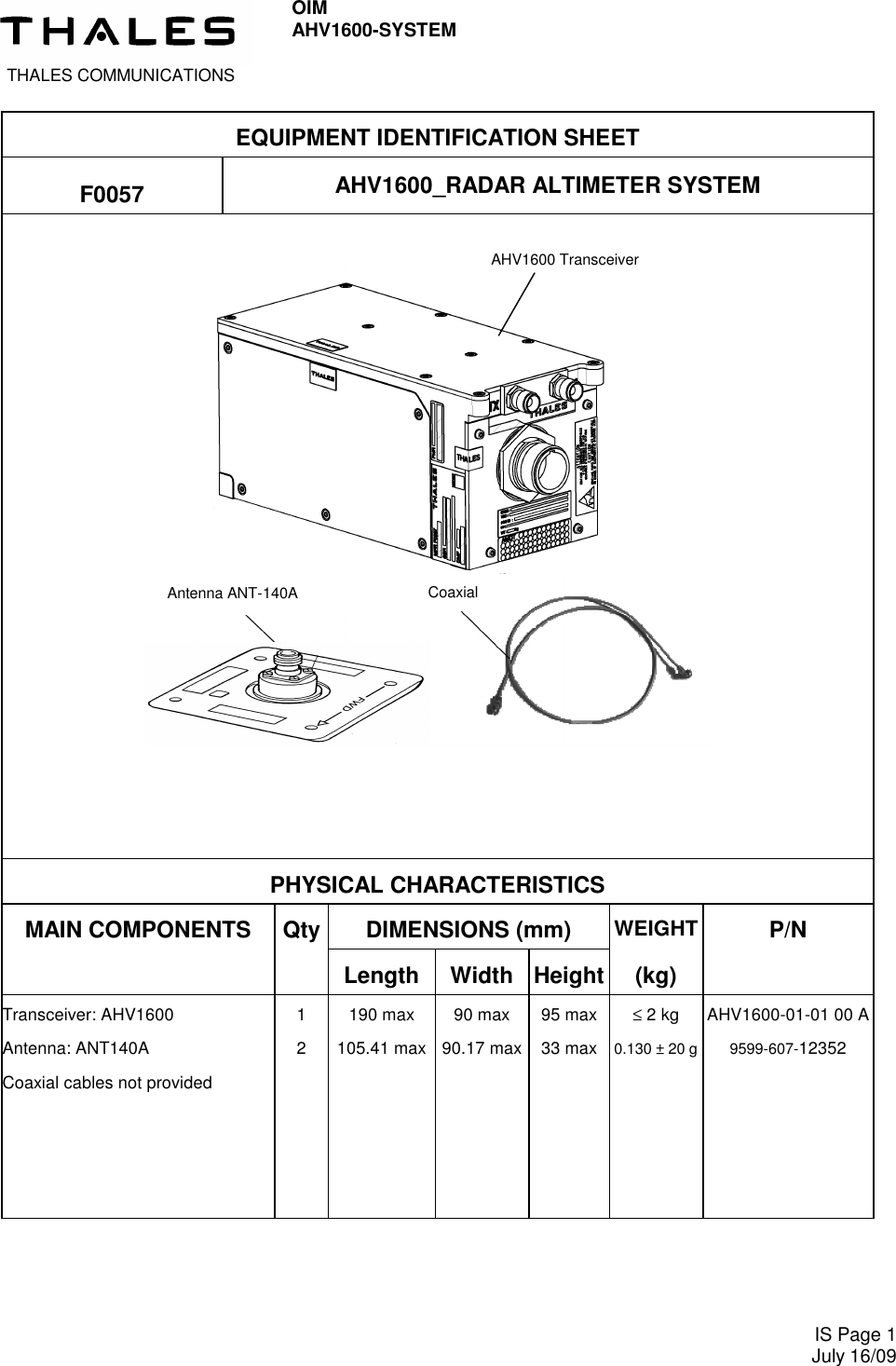
![THALES Communications OIM AHV1600-SYSTEM IS Page 2 Nov 25/09 AHV1600 TRANSCEIVER TECHNICAL CHARACTERISTICS 1- Nominal power supply: 28 Vdc 2- Power consumption: 20 W max (18 W typical) 3- Power input interruption : ≤ 2 ms 4- Connection: MIL C 39012 (TNC / RF connectors), MIL C38999 (main connectors) 5- Performance: − Transmission : FM/CW. − Frequency Range : 4.2 GHz to 4.4 GHz. − Frequency Deviation : 123 MHz typical. − Transmitted Power : + 18 dBm (63 mW) max typical. − Height range accuracy : The maximum error, at every simulated height and within the temperature range - 40°C / + 70°C is : ±(2 ft + 2 % H) 6- Environmental conditions: DO160E Cat. [(B4)X]BBB[RG]XWFDFSZZAZ[ZC][HF]M[(A4G33)(A3J33)]XXAX AHV1600 TRANSCEIVER FUNCTIONAL CHARACTERISTICS – FUNCTIONS OF THE EQUIPMENT: - Provide height Above Ground Level (AGL). – EQUIPMENT INTERFACE: - Transmission antenna. - Reception antenna. - 28 Vdc supply - Main connector](https://usermanual.wiki/Thales-Communications/AHV1600.USER-MANUAL-REV1/User-Guide-1207478-Page-22.png)
![THALES COMMUNICATIONS OIM AHV1600-SYSTEM Page 119 July 16/09 (5) PERFORMANCE •••• Altitude: 5000 ft •••• Height accuracy: (± 2 ft + 2% of the true height) D. ENVIRONMENTAL CONDITIONS DO160E Cat. [(B4)X]BBB[RG]XWFDFSZZAZ[ZC][HF]M[(A4G33)(A3J33)]XXAX Environmental Condition DO160E DO160E section Description of conducted test Temperature and altitude 4 Category B4 Temperature variation 5 Category B Humidity 6 Category B Operational shocks and crash safety 7 Category B Vibration 8 Category R curve G Explosive atmosphere 9 Not required Category X Waterproofness 10 Category W Fluids susceptibility 11 Category F Sand and dust 12 Category D Fungus resistance 13 Category F Salt Fog 14 Category S Magnetic effect 15 Category Z Power input 16 Category Z TCF declares that the AHV1600 Transceiver is able to withstand momentary power interruption up to 2ms (Test condition 1 of table 16-3). Voltage spike 17 Category A Audio frequency conducted suscepti-bility – power inputs 18 Category Z Induced signal susceptibility 19 Category ZC Radio frequency susceptibility (radi-ated and conducted) 20 Category H for Conducted Susceptibility Category F for Radiated Susceptibility Emission of radio frequency energy 21 Category M Lightning induced transient suscepti-bility 22 Pin Injection Tests : Equipment tested to Category (A4) for power lines and (A3) for interconnecting lines. Cable Bundle Tests : Equipment tested to Category (G33) for power lines and (J33) for interconnecting lines. Lightning direct effects 23 Not required Category X Icing 24 Not required Category X Electrostatic discharge 25 Category A Fire, Flammability 26 Not required Category X](https://usermanual.wiki/Thales-Communications/AHV1600.USER-MANUAL-REV1/User-Guide-1207478-Page-45.png)