Thales Communications AHV1600 Radio-altimeter Transceiver User Manual OIM AHV1600 REV01
THALES Communications Radio-altimeter Transceiver OIM AHV1600 REV01
Contents
- 1. OIM
- 2. Users Manual
- 3. USER MANUAL REV1
USER MANUAL REV1

OPERATION AND INSTALLATION MANUAL
AHV1600 RADAR ALTIMETER SYSTEM
TS Page 1
NOV 25/09
TRANSMITTAL SHEET
TO: HOLDERS OF OPERATION AND INSTALLATION MANUAL P/N: 36719226-AB, revision No.
1, dated NOV 25/09 is attached and covers all components held by every operator.
P/N: 36719226-AB.
The OIM revision No. 1, dated NOV 25/09 is attached and covers all components held by
every operator.
FILING INSTRUCTIONS
Revision 1 replaces original issue.
Original issue is deleted.
HIGHLIGHTS:
To correct the OIM P/N: 36719226-AA Original issue.

OIM
AHV1600 SYSTEM
TS Page 2
NOV 25/09
THIS PAGE INTENTIONALLY LEFT BLANK

THALES Communications
ORIGINAL ISSUE : July 16/09
REF : 36719226-AB
REVISION No : 01
TP Page 1/2
Nov 25/09
O
PERATION
AND
I
NSTALLATION
M
ANUAL
AHV1600
Radar Altimeter System

THALES Communications
OIM
AHV1600-SYSTEM
TP Page 2/2
July 16/09

THALES Communications
OIM
AHV1600-SYSTEM
ROR Page 1/2
NOV 25/09
RECORD OF REVISIONS
INSERTION INSERTION
REVISION REVISION REVISION
REVISION
N° DATE DATE BY N° DATE DATE BY
01 2009/11/25

THALES Communications
OIM
AHV1600-SYSTEM
ROR Page 2/2
July 16/09

THALES Communications
OIM
AHV1600-SYSTEM
RTR Page 1/2
July 16/09
RECORD OF TEMPORARY REVISIONS
TEMPORARY REVISIONS INSERTED DELETED
N° PAGE N° DATE BY REVISION N° BY

THALES Communications
OIM
AHV1600-SYSTEM
RTR Page 2/2
July 16/09

THALES Communications
OIM
AHV1600-SYSTEM
SBL Page 1/2
July 16/09
SERVICE BULLETIN LIST
SERVICE
BULLETIN N° REVISION
N° REVISION
DATE SUBJECT

THALES Communications
OIM
AHV1600-SYSTEM
SBL Page 2/2
July 16/09

THALES COMMUNICATIONS
OIM
AHV1600-SYSTEM
LIST OF EFFECTIVE PAGES
SUBJECT PAGE DATE SUBJECT PAGE DATE
LEP Page 1/2
Nov 25/09
Title Page R 1 NOV 25/09
2 BLANK
Record of Revisions R 1 NOV 25/09
2 BLANK
Record of Temporary 1 JULY 16/09
Revisions 2 BLANK
Service Bulletin List 1 JULY 16/09
2 BLANK
List of Effective Pages R 1 NOV 25/09
2 BLANK
Table of Contents 1 JULY 16/09
2 JULY 16/09
Table of Figures 1 JULY 16/09
2 BLANK
Introduction 1 JULY 16/09
2 JULY 16/09
3 JULY 16/09
4 JULY 16/09
Identification sheet 1 JULY 16/09
R 2 NOV 25/09
General 1 JULY 16/09
2 JULY 16/09
3 JULY 16/09
4 JULY 16/09
Presentation 101 JULY 16/09
102 JULY 16/09
103 JULY 16/09
104 JULY 16/09
105 JULY 16/09
106 JULY 16/09
107 JULY 16/09
108 JULY 16/09
109 JULY 16/09
110 JULY 16/09
111 JULY 16/09
112 JULY 16/09
113 JULY 16/09
114 JULY 16/09
115 JULY 16/09
116 JULY 16/09
117 JULY 16/09
118 JULY 16/09
119 JULY 16/09
120 JULY 16/09
121 JULY 16/09
122 JULY 16/09
123 JULY 16/09
Installation 201 JULY 16/09
202 JULY 16/09
203 JULY 16/09
204 JULY 16/09
205 JULY 16/09
206 JULY 16/09
207 JULY 16/09
208 JULY 16/09
209 JULY 16/09
210 JULY 16/09
211 JULY 16/09
Operation 301 JULY 16/09
302 JULY 16/09

THALES Communications
OIM
AHV1600-SYSTEM
LEP Page 2/2
July 16/09

THALES COMMUNICATIONS
OIM
AHV1600-SYSTEM
TC Page 1/2
July 16/09
TABLE OF CONTENTS
PAGES
INTRODUCTION.................................................................................................................................................1
1.
GENERAL INFORMATION ......................................................................................................................1
2.
BLOCK PAGE NUMBERS FOR SECTIONS............................................................................................1
3.
UPDATING ...............................................................................................................................................1
4.
ADVISORIES............................................................................................................................................2
A.
SAFETY INSTRUCTIONS / ELECTROSTATIC DISCHARGE PRECAUTIONS..................................2
B.
SHORT - CIRCUIT PRECAUTIONS.....................................................................................................2
5.
UNCOMMON ABBREVIATIONS AND ACRONYMS ...............................................................................3
GENERAL............................................................................................................................................................1
1.
AHV1600 RADAR ALTIMETER MAIN FUNCTION..................................................................................1
2.
AHV1600 BASIC PRINCIPLE...................................................................................................................1
3.
BUILT IN TEST FUNCTION.....................................................................................................................3
A.
POWER-UP BUILT IN TEST (PBIT).....................................................................................................3
B.
INITIATED BUILT IN TEST (IBIT) ........................................................................................................3
C.
CONTINUOUS BUILT IN TEST (CBIT) ................................................................................................3
4.
AIRCRAFT INTERFACE ..........................................................................................................................3
PRESENTATION.............................................................................................................................................101
1.
AHV1600 RADAR ALTIMETER SYSTEM GENERAL DESCRIPTION................................................101
2.
AHV1600 TRANSCEIVER....................................................................................................................102
A.
EXTERNAL CHARACTERISTICS....................................................................................................103
B.
INTERNAL SUB-ASSEMBLIES........................................................................................................106
C.
FUNCTIONAL CHARACTERISTICS................................................................................................106
3.
OPERATIONAL INTERFACES ............................................................................................................117
A.
POWER SUPPLY .............................................................................................................................117
B.
DIGITAL ARINC429 INTERFACE ....................................................................................................117
C.
AID SIGNALS INTERFACE ..............................................................................................................118
D.
ENVIRONMENTAL CONDITIONS ...................................................................................................119
E.
IN FLIGHT CONDITIONS.................................................................................................................120
4.
ANTENNA ANT-140A...........................................................................................................................120
A.
GENERALITIES ON ANTENNA ANT-140A .....................................................................................120
B.
PHYSICAL CHARACTERISTICS .....................................................................................................120
C.
FUNCTIONAL CHARACTERISTICS................................................................................................122
5.
COAXIAL CABLES LENGHT ...............................................................................................................122
INSTALLATION ...............................................................................................................................................201
1.
GENERAL CONDITIONS.....................................................................................................................201
A.
POWER SUPPLY .............................................................................................................................201
B.
LOCATION........................................................................................................................................201
C.
WATER, SAND, AND DUST TIGHTNESS.......................................................................................201
D.
MOUNTING.......................................................................................................................................201
E.
INSTALLATION CONDITIONS.........................................................................................................201
2.
STEP BY STEP TRANSCEIVER INSTALLATION...............................................................................202
A.
CHOICE OF ANTENNAE LOCATION..............................................................................................203
B.
ANTENNA MOUNTING ....................................................................................................................204
C.
CONNECTION..................................................................................................................................205
3.
VERIFICATION.....................................................................................................................................205
A.
GROUND TESTS .............................................................................................................................205
B.
IN FLIGHT TESTS ............................................................................................................................205

THALES Communications
OIM
AHV1600-SYSTEM
TC Page 2/2
July 16/09
PAGES
4.
FUNCTIONAL CONNECTIONS WITH RELATED EQUIPMENT.........................................................205
A.
INTERFACES CONNECTIONS........................................................................................................205
B.
GROUNDING AND BONDING..........................................................................................................206
C.
COOLING OF THE EQUIPMENT .....................................................................................................207
D.
HANDLING........................................................................................................................................207
5.
EQUIPMENT INPUTS / OUTPUTS ......................................................................................................207
A.
MAIN CONNECTOR J1 ....................................................................................................................207
B.
RX/TX ANTENNA..............................................................................................................................210
OPERATION....................................................................................................................................................301
1.
RADAR ALTIMETER ENERGIZATION ................................................................................................301
2.
FUNCTIONNAL TEST ..........................................................................................................................301
3.
NORMAL OPERATING MODE.............................................................................................................301
4.
OUT OF RANGE OPERATION ............................................................................................................301
5.
FAILURE MODE ...................................................................................................................................301
6.
DEFAULT OPERATING INSTRUCTIONS ...........................................................................................302
7.
OPERATIONAL LEVEL MAINTENANCE TASK...................................................................................302
A.
REMOVING THE TRANSCEIVER....................................................................................................302
B.
INSTALLING THE SPARE TRANSCEIVER .....................................................................................302

THALES COMMUNICATIONS
OIM
AHV1600-SYSTEM
TF Page 1/2
July 16/09
TABLE OF FIGURES
PAGES
Figure 1 – AHV1600 TRANSCEIVER SYSTEM............................................................................................4
Figure 101 – AHV1600 RADAR ALTIMETER SYSTEM BLOCK DIAGRAM ............................................101
Figure 102 –
AHV1600 TRANSCEIVER - GENERAL VIEW
.............................................................102
Figure 103 – OVERALL DIMENSIONS .....................................................................................................103
Figure 104 – MANUFACTURING SERIAL NUMBER LABEL ...................................................................104
Figure 105 – THALES IDENTIFICATION LABEL......................................................................................104
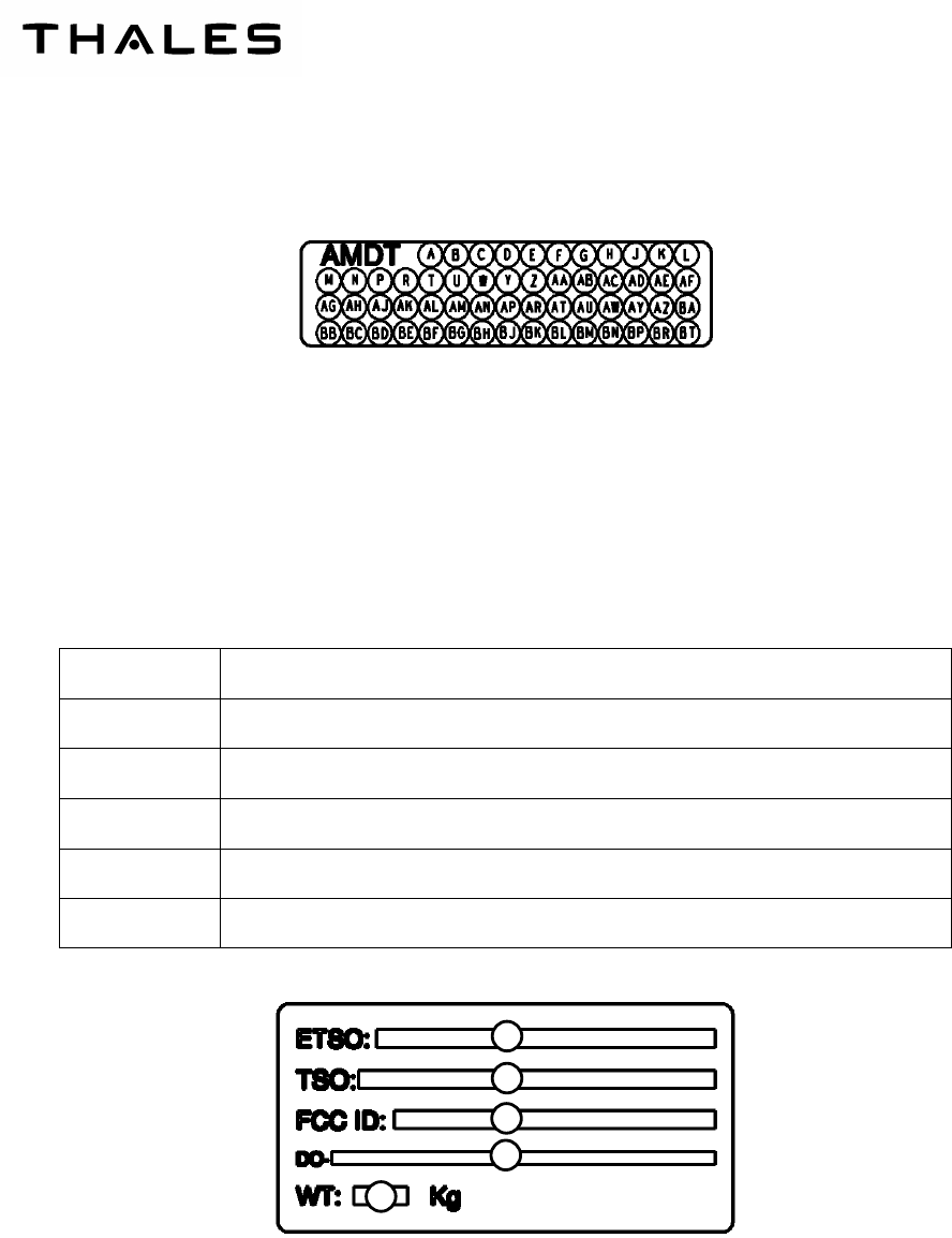
Figure 106 – AMENDMENT LABEL ..........................................................................................................105
Figure 107 – SPECIFIC LABEL.................................................................................................................105
Figure 108 – ORGANIZATION OF HEIGHT DATA WORD LABEL “164” ................................................108
Figure 109 – ORGANIZATION OF STATUS DATA WORD LABEL “271”................................................110
Figure 110 – ORGANIZATION OF STATUS DATA WORD LABEL “272"................................................112
Figure 111 – ORGANIZATION OF FIRST EQUIPMENT IDENTIFIER DATA WORD LABEL “371”........112
Figure 112
– ORGANIZATION OF INTERMEDIATE EQUIPMENT IDENTIFIER DATA WORD LABEL “371” .......
113
Figure 113 – ORGANIZATION OF LAST EQUIPMENT IDENTIFIER DATA WORD LABEL “371” .........113
Figure 114 – ORGANIZATION OF STATUS DATA WORD LABEL “377"................................................114
Figure 115 – ORGANIZATION OF HEIGHT DATA WORD LABEL “165" ................................................116
Figure 116 – ANT-140A INNER SIDE.......................................................................................................121
Figure 117 – ANT-140A OUTER SIDE......................................................................................................121
Figure 201 – ANT-140A – ANTENNAE SEPARATION AND ORIENTATION ..........................................204
Figure 202 – SURFACES BONDING CONTACT OUTLINES ..................................................................206
Figure 203 – INTERCONNECTIONS........................................................................................................211

THALES Communications
OIM
AHV1600-SYSTEM
TF Page 2/2
July 16/09

THALES COMMUNICATIONS
OIM
AHV1600-SYSTEM
INTRO Page 1
July 16/09
INTRODUCTION
1. GENERAL INFORMATION
The manual contains the information for the installation and the operation of the AHV1600 Radar Altimeter
P/N:
AHV1600-01-01 00 A
for Aircraft.
2. BLOCK PAGE NUMBERS FOR SECTIONS
Each section has a separate block page number:
− 1 - 99 : General
− 101 - 199 : Presentation
− 201 - 299 : Installation
− 301 - 399 : Operation
All values have been given in the units (or multiples or sub-multiples of these units) of the International Sys-
tem (S.I.). It is possible that the values are given in more usual units. The English equivalents are given into
brackets.
3. UPDATING
In case of update of the manual, detailed instructions for the insertion and deletion of applicable pages will be
given.
Revised texts, new texts or deleted texts will be located with a vertical black line in the margin.

THALES Communications
OIM
AHV1600-SYSTEM
INTRO Page 2
July 16/09
4. ADVISORIES
A. SAFETY INSTRUCTIONS / ELECTROSTATIC DISCHARGE PRECAUTIONS
This graphic symbol showing a hand on a dark background (to IEC 747-1 standard) means that the
equipment on which it appears (assembly or subassembly) contains components sensitive to elec-
trostatic discharges.
The following rules shall be complied with when carrying out any type of servicing on equipment
bearing this symbol:
− The equipment shall be placed on a conducting or antistatic-working surface grounded through a
resistance of between 250 kohm and 1 Mega-ohm.
− The operator shall wear a cotton smock and shall be linked with the working surface by a con-
ducting wristband through a resistance of 1 Mega-ohm.
− Soldering iron shall be grounded.
− The transport and storage of parts removed from the equipment (printed board assemblies,
modules, hybrid circuits, etc.) shall be done with conductive or antistatic packaging.
B. SHORT - CIRCUIT PRECAUTIONS
The inputs/outputs (I/O) are protected from short circuits but, by precautions no servicing shall be
performed on any active or passive components while the equipment is energized.

THALES COMMUNICATIONS
OIM
AHV1600-SYSTEM
INTRO Page 3
July 16/09
5. UNCOMMON ABBREVIATIONS AND ACRONYMS
The following abbreviations, acronyms, and symbols are used in this manual:
Abbreviation/Acronym Identification
A/D Analogical/Digital
AGL Above Ground Level
AID Aircraft Installation Delay
ANT ANTenna
AU Altimeter Unit
BIT Built In Test
CBIT Continuous Built In Test
CR Carriage Return
CSCI Computer Software Configuration Item
CTZ Coastal Transition Zone
CW Continuous Wave
D/A Digital/Analogical
dB deciBel
dBm deciBel milliwatt
DC Direct Current
DMB Digital and Management Board
EMC ElectroMagnetic Compatibility
Fb Beat Frequency
FM Frequency Modulation
FT Functional Test
Fore Forward
HI HIgh
HIRF High Intensity Radiated Fields (Lightning)
IBIT Initiated Built-In-Test
IEC International Electronical Commission
I/O Input /Output
LO Low
LRU Line Replaceable Unit
LSB Lower Significant Bit
MAX MAXimum
MIN MINimum
MPC Multi Purpose Computer
NCD No height Computer Data
NO Normal Operation
PBIT Power On Built In Test
PC Printed Card
P/N Part Number
R/A or RA Radar Altimeter
RET RETurn
RF Radio Frequency
RL Return Loss
Rx Reception

THALES Communications
OIM
AHV1600-SYSTEM
INTRO Page 4
July 16/09
Abbreviation/Acronym Identification
S.I. International System
ST Saw Tooth
SWR Standing Wave Ratio
Tx Transmission
USB Upper Significant Bit
VCO Voltage Controlled Oscillator
THALES COMMUNICATIONS
OIM
AHV1600-SYSTEM
IS Page 1
July 16/09
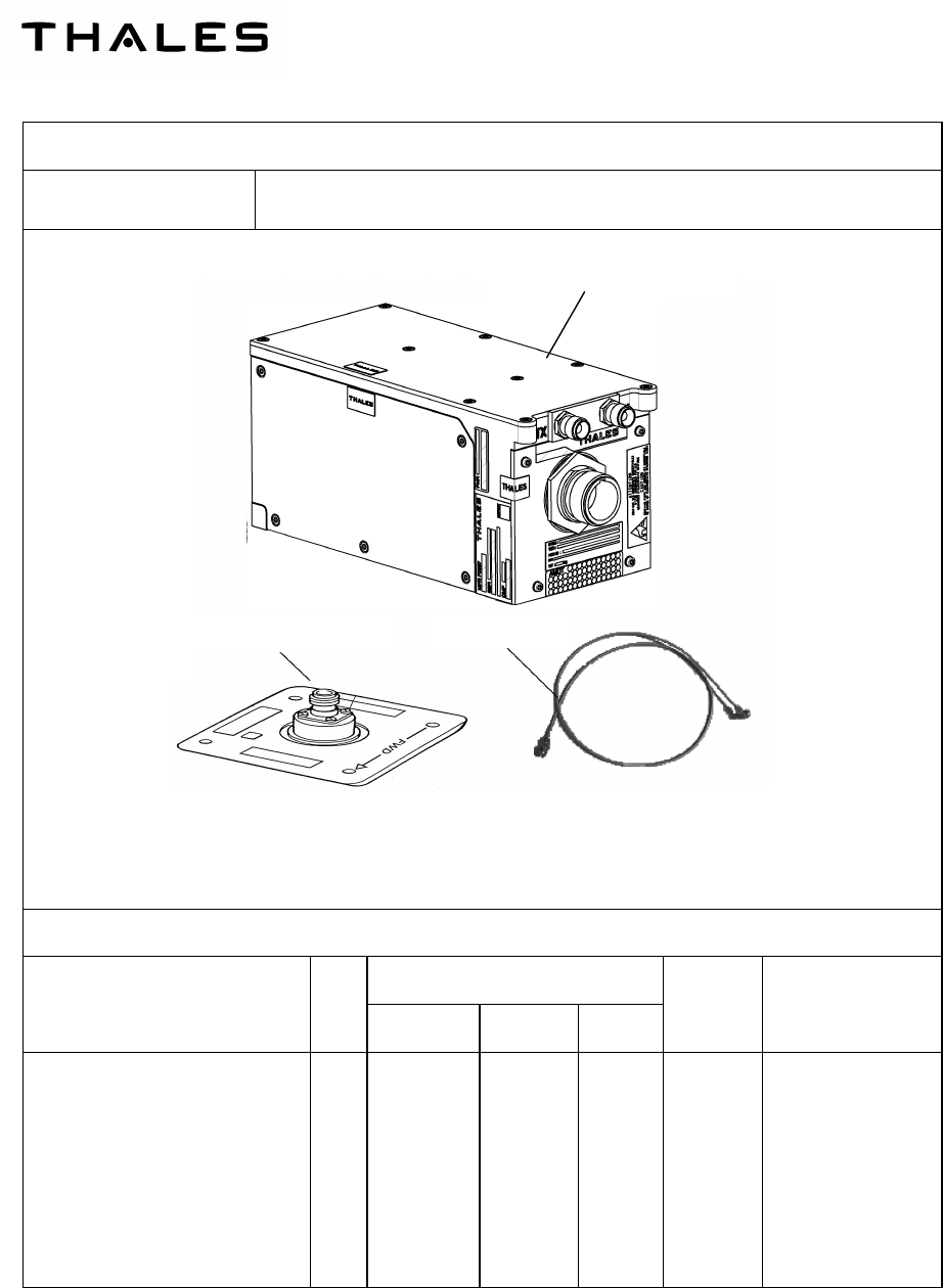
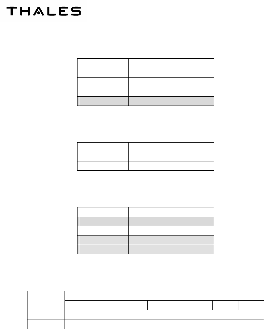
EQUIPMENT IDENTIFICATION SHEET
F0057 AHV1600_RADAR ALTIMETER SYSTEM
PHYSICAL CHARACTERISTICS
MAIN COMPONENTS Qty
DIMENSIONS (mm)
WEIGHT
P/N
Length Width Height
(kg)
Transceiver: AHV1600
Antenna: ANT140A
Coaxial cables not provided
1
2
190 max
105.41 max
90 max
90.17 max
95 max
33 max
≤ 2 kg
0.130 ± 20 g
AHV1600-01-01 00 A
9599-607-
12352
Antenna ANT-140A Coaxial
AHV1600 Transceiver

THALES Communications
OIM
AHV1600-SYSTEM
IS Page 2
Nov 25/09
AHV1600 TRANSCEIVER TECHNICAL CHARACTERISTICS
1- Nominal power supply: 28 Vdc
2- Power consumption: 20 W max (18 W typical)
3- Power input interruption : ≤ 2 ms
4- Connection: MIL C 39012 (TNC / RF connectors), MIL C38999 (main connectors)
5- Performance:
− Transmission : FM/CW.
− Frequency Range : 4.2 GHz to 4.4 GHz.
− Frequency Deviation : 123 MHz typical.
− Transmitted Power : + 18 dBm (63 mW) max typical.
− Height range accuracy : The maximum error, at every simulated height and within the temperature
range - 40°C / + 70°C is : ±(2 ft + 2 % H)
6- Environmental conditions:
DO160E
Cat. [(B4)X]BBB[RG]XWFDFSZZAZ[ZC][HF]M[(A4G33)(A3J33)]XXAX
AHV1600 TRANSCEIVER FUNCTIONAL CHARACTERISTICS
– FUNCTIONS OF THE EQUIPMENT:
- Provide height Above Ground Level (AGL).
– EQUIPMENT INTERFACE:
- Transmission antenna.
- Reception antenna.
- 28 Vdc supply
- Main connector
THALES COMMUNICATIONS
OIM
AHV1600-SYSTEM
Page 1
July 16/09
GENERAL
1. AHV1600 RADAR ALTIMETER MAIN FUNCTION
The main function of the AHV1600 Radar Altimeter is to provide the height information, via an ARINC 429
digital bus, to the aircraft navigation system, in a range from 0 ft up to 5000 ft.
It uses the fact that the electromagnetic waves propagate through the air at a constant speed c, which is the
speed of the light.
The height information is defined as the shortest distance to the "terrain" (ground or sea).
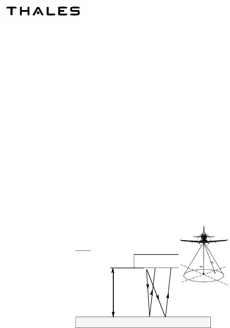
2. AHV1600 BASIC PRINCIPLE
The AHV1600 Transceiver measures altitude above ground as a function of elapsed time from the transmis-
sion of the electromagnetic wave to its return after reflection from the ground. The transmission time is directly
proportional to the height above ground level.
It measures the shortest delay τo between the transmitted wave and the received wave, linked to the mini-
mum distance to the terrain Ηo by the formula:
TERRAIN (GROUND/SEA)
h
t=2
h/c
AIRCRAFT
MISSILE
The AHV1600 Transceiver principle of operation is the FM/CW (Frequency Modulation / Continuous Wave)
with variable slope modulation. The basic principle of this technique is to generate a saw tooth waveform with
a slope of modulation varying as a function of altitude as shown on the figure below. The transmitted wave is
linearly modulated in frequency by the saw tooth.
c
Ho
o.2
=
τ
THALES Communications
OIM
AHV1600-SYSTEM
Page 2
July 16/09
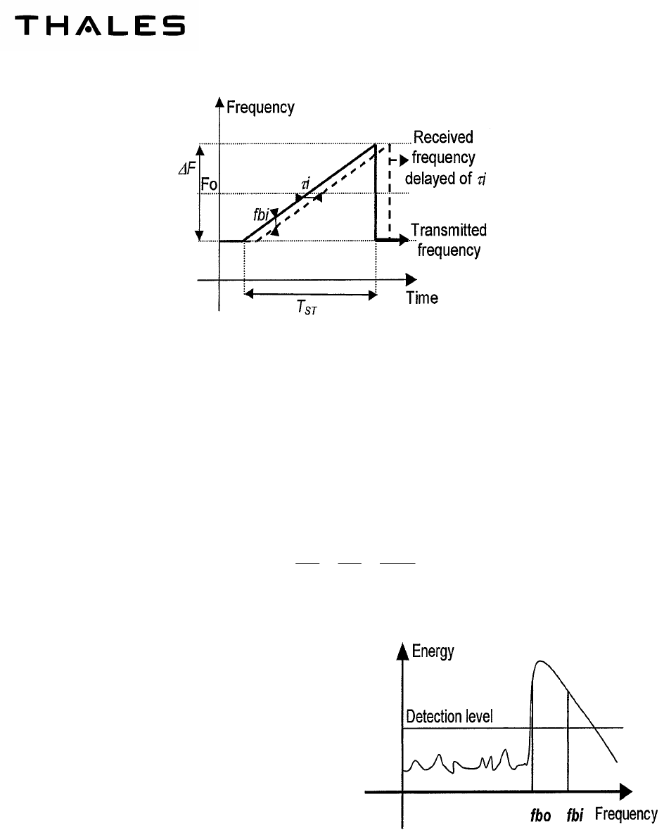
The AHV1600 Transceiver performs FM/CW modulation transmissions that are beat against the received
reflection. The variable slope modulation allows the beat frequency to be maintained in a given bandwidth
(window of 60 kHz to 110 kHz around centre frequency of 80 kHz). The window is then analysed through the
equivalent of a 1 kHz bandwidth filter sweeping from 15 kHz to 110 kHz. The evaluation of the aircraft altitude
is based on the measurement of the saw tooth duration and the position of the echo frequency in the window.
The detection of the beat frequency spectrum is performed by a digital signal processing function.
The transmitted wave is linearly modulated in frequency by a saw tooth.
A beat signal is then obtained by mixing the transmitted waves F(t) and received waves F(t-
τ
i). At every in-
stant, the frequency fbi of this signal is equal to: fbi = F(t) - F(t-
τ
i)
As the modulation is linear fbi is linked to
τ
i and then to Hi by the formulae:
fbi
F
i
T
Hi
c T
ST ST
∆= =
τ
2.
.
The fbi frequencies form the beat signal spectrum.
This spectrum is constituted of all the frequencies from
the ground and the thermal noise as well.
To enable a measurement of fbo with a probability of
noise detection compatible with the integrity require-
ments of the Radio Altimeter, a detection level is de-
fined.
Only frequencies, which appear in the beat signal with
energy above this level are taken into account.
As the frequencies fbi and the heights Hi are propor-
tional, the minimum distance to the ground Ho is linked
to the minimum frequency fbo of the spectrum.
The Radio Altimeter then measures this frequency fbo,
the leading edge of the spectrum.
In the case of the Radio Altimeter, the frequency excursion
F
∆
is fixed and T
ST
is made proportional to Ho by
a feedback loop that keeps fbo in a constant frequency range. The accurate measurement of the minimum fb

THALES COMMUNICATIONS
OIM
AHV1600-SYSTEM
Page 3
July 16/09
in the beat signal spectrum provides an accurate height measurement, and a T
ST
for the feedback loop to
keep fbo in its defined frequency range from one measurement to the other. Hence the relationship :
Ho K fbo
=
.
where
F
Tc
K
ST
∆
=
.
2
.
3. BUILT IN TEST FUNCTION
The AHV1600 Transceiver implements an operational built-in test (BIT) in the following steps:
A. POWER-UP BUILT IN TEST (PBIT)
The AHV1600 Transceiver is capable of carrying out a performance test upon completion of the ini-
tialization sequence after power up to confirm the serviceability of the assembly. This test is per-
formed in 3 s.
B. INITIATED BUILT IN TEST (IBIT)
The AHV1600 Transceiver is capable of carrying out a performance test to confirm the serviceability
of the Transceiver upon receipt of the discrete input signal “FCT_TST“. This test is performed in 3s.
C. CONTINUOUS BUILT IN TEST (CBIT)
The AHV1600 Transceiver is carrying out a continuous test of performance of the system as a back-
ground task. Continuous BIT provides coverage to the minimum extent possible without interfering
with the normal Transceiver operation.
The BIT is controlled by the software embedded by the equipment.
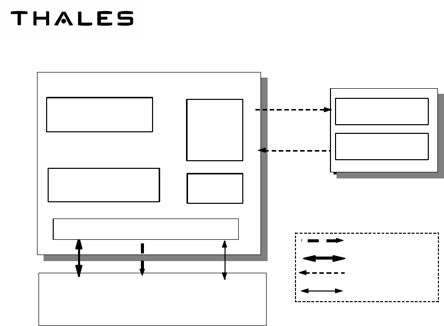
4. AIRCRAFT INTERFACE
The AHV1600 transceiver interfaces with the following equipment :
− Airborne navigation computer,
− Airborne power supply,
− Two antennae.
The figure 1 shows a block diagram of the AHV1600 radar altimeter system:
THALES Communications
OIM
AHV1600-SYSTEM
Page 4
July 16/09
AVH1600 TRANSCEIVER
Radio
Module
Digital/Management
Board
Mother Board
(Including I/O) Power
supply
ANT140A
4.2 /4.4 GHz Antenna
Rx
Reception
Tx
Emission
RS232 lines
Discretes
RF signals
ARINC 429 lines
I/O maintenance
Height and
status
I/O Dedicated
information
HIRF Stage
ANT140A
4.2 /4.4 GHz Antenna
Figure
1
–
AHV1600 RADAR ALTIMETER SYSTEM
THALES COMMUNICATIONS
OIM
AHV1600-SYSTEM
Page 101
July 16/09
PRESENTATION
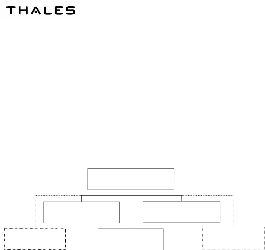
1. AHV1600 RADAR ALTIMETER SYSTEM GENERAL DESCRIPTION
The Radar Altimeter System, named AHV1600, consists of three LRU (Line Replaceable Unit) and is com-
posed of:
− one AHV1600 transceiver,
− one antenna ANT-140A to transmit radio frequency (RF) signal,
− one antenna ANT-140A to receive radio frequency (RF) signal.
Two coaxial cables (not provided) are necessary:
− one transmission cable, to connect the transmission antenna to the transceiver,
− one reception cable, to connect the reception antenna to the transceiver.
Transmission antenna ANT140A
LRU
Transceiver AHV1600
LRU
Reception antenna ANT140A
LRU
AHV1600_RADAR ALTIMETER
Reception cable
Transmission cable
Figure 101 – AHV1600 RADAR ALTIMETER SYSTEM BLOCK DIAGRAM
The AHV1600 is an autonomous system mounted on an aircraft and connected to:
− 28 Vdc power supply line:
• “P28V” and “RET28V” signals.
− Transmit and receive antennae for Radio Frequency (RF) signals through coaxial cables (“TX and
RX” signals).
− Navigation and guidance systems through:
• Dual differential ARINC429 digital output serial line (“TX429_HI_1, TX429_LO_1 and
TX429_HI_2, TX429_LO_2” signals).
THALES Communications
OIM
AHV1600-SYSTEM
Page 102
July 16/09
• Two discrete inputs (“FCT_TST and TST_INH” signals).
• Configurable inputs (“AID<2..0>, AID_P and SDI_SEL” signals).
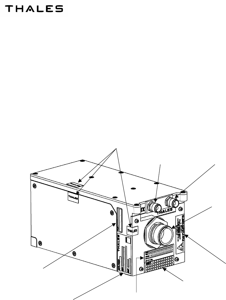
2. AHV1600 TRANSCEIVER
The AHV1600 Transceiver is a compact and very light system. It is intended to fit the aircraft.
It is fixed on the aircraft structure by means of four M6 screws.
The unit is made up of a chassis with a front panel. The front panel is equipped with:
− one main connector,
− two coaxial connectors:
• one reception connector« Rx »,
• one transmission connector« Tx ».
Figure 102 –
AHV1600 TRANSCEIVER - GENERAL VIEW
Manufacturing serial number label
THALES identification label
Specific label
amendment label
ESD (Electro Static Discharge) label
Immunity label
Transmission connector
Reception connector
Main connector
THALES COMMUNICATIONS
OIM
AHV1600-SYSTEM
Page 103
July 16/09
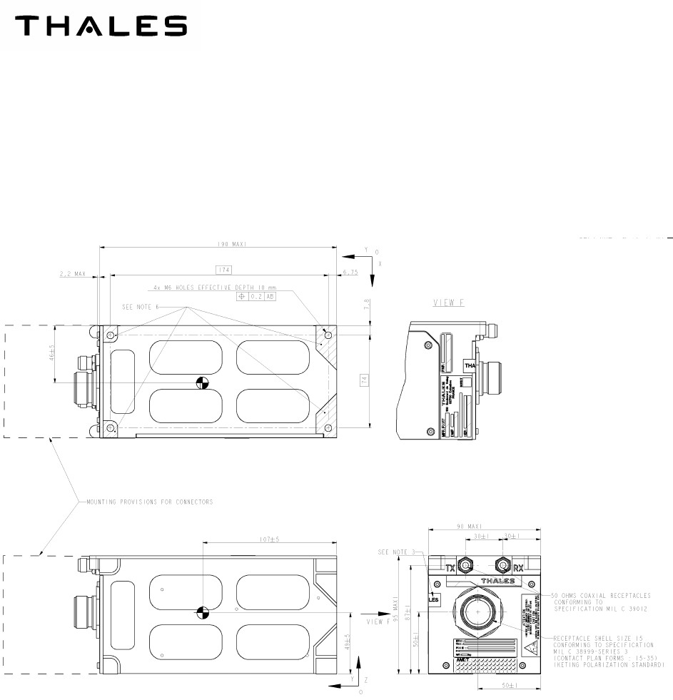
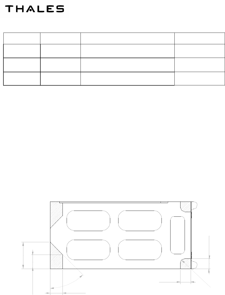
A. EXTERNAL CHARACTERISTICS
(1) PHYSICAL CHARACTERISTICS
Dimensions (see figure 103): max. 190 x 90 x 95 mm.
The weight of the unit is < 2 kg.
Figure 103 – OVERALL DIMENSIONS
Note: all dimensions are in mm
(2) FRONT PANEL
The front panel bears the antennae connectors, the main connectors , the specific label, the
amendment label, the ESD label and the immunity label.
All connectors are equipped with special caps provided electrical shielding as well as mechanical
protection.
THALES Communications
OIM
AHV1600-SYSTEM
Page 104
July 16/09
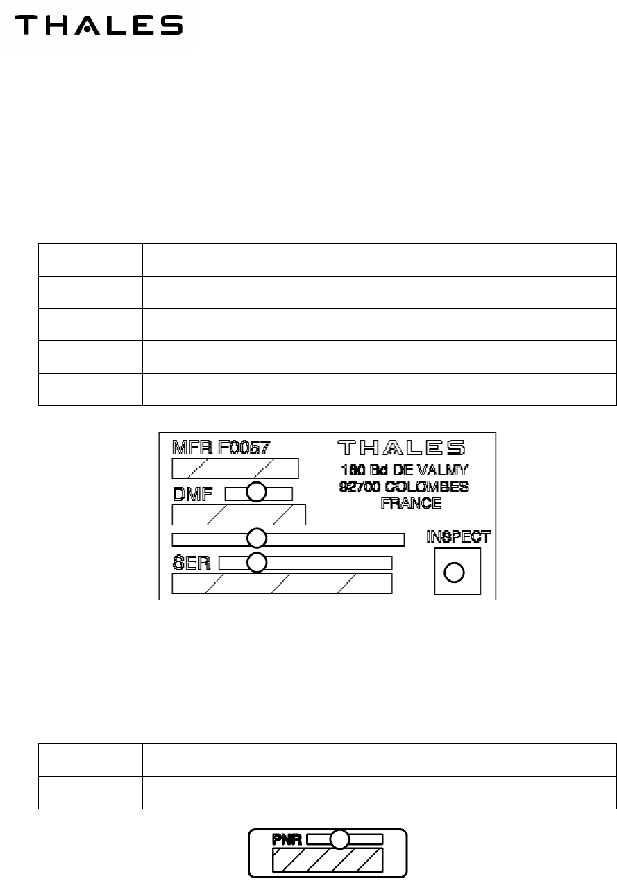
(3) IDENTIFICATION
(a) Manufacturing Serial Number Label
The manufacturing serial number label is stuck on the left side (refer to Figure 102). It is divided
into four fields, which provide the following indications:
Field Number Field
1 Serial number
2 LRU Description
3 Date of manufacturing
4 Inspection stamp
(b) THALES Identification Label
The THALES identification label is stuck on the left side (refer to Figure 102). One field pro-
vides the following indication:
Field Number Field
1 THALES commercial part number
Figure 104 – MANUFACTURING SERIAL NUMBER LABEL
Figure 105 – THALES IDENTIFICATION LABEL
1
2
3
4
1
THALES COMMUNICATIONS
OIM
AHV1600-SYSTEM
Page 105
July 16/09
(c) Amendment label
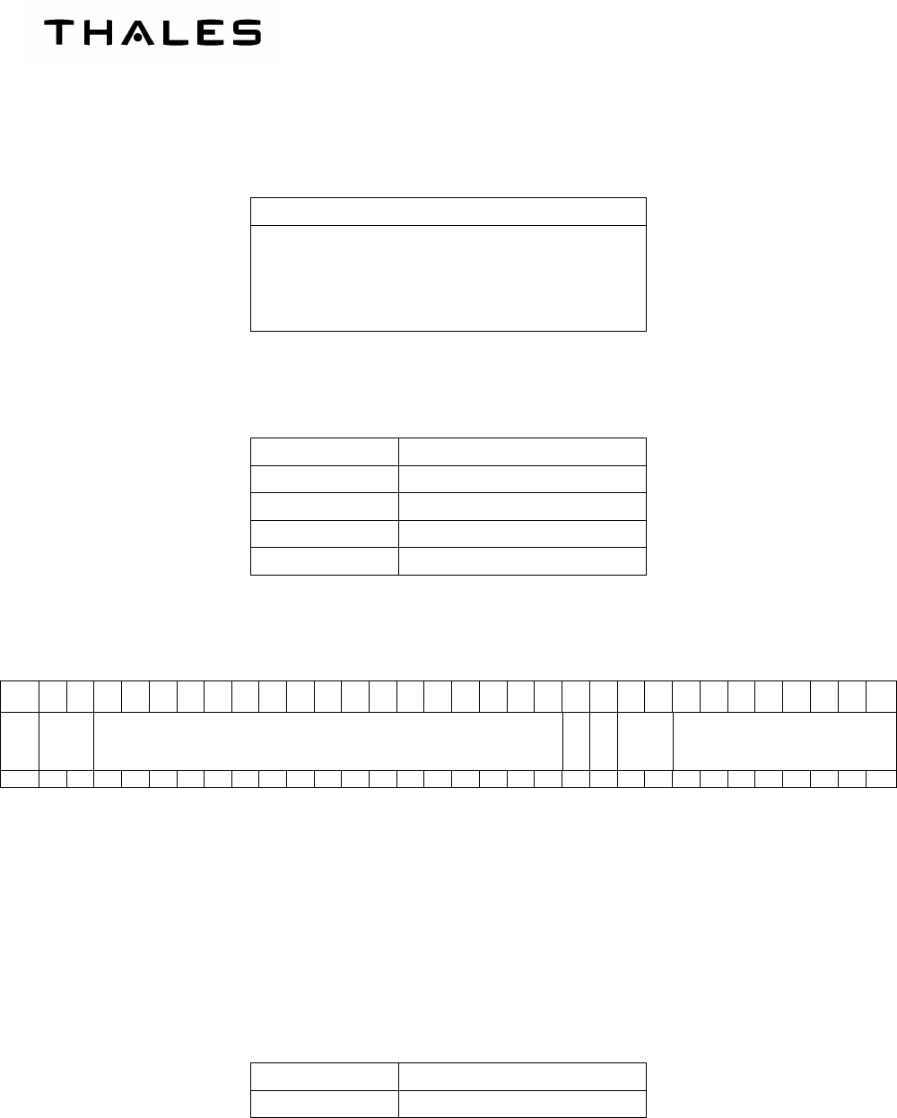
(d) Specific label
The specific label is stuck on the front panel (refer to Figure 102). It is divided into five fields,
which provide the following indications:
Field Number Field
1 ETSO certification number
2 TSO certification number
3 FCC ID designation
4 DO designation
5 Weight
Figure 106 – AMENDMENT LABEL
Figure 107 – SPECIFIC LABEL
1
2
3
4
5

THALES Communications
OIM
AHV1600-SYSTEM
Page 106
July 16/09
B. INTERNAL SUB-ASSEMBLIES
The AHV1600 Transceiver contains the following sub-assemblies:
– The Digital chassis:
•
••
•
Performs the High Intensity Radiated Field (HIRF) protection, internal module interconnection,
digital and management processor capacity and power supply distribution,
•
••
•
Provides the helicopter with the mechanical and electrical interfaces,
•
••
•
Provides the hardware support of the downloaded software’s.
– The radio module:
•
••
•
Performs the Radio Frequency (RF) signal emission, the Radio Frequency (RF) signal reception
and the Beat Frequency (BF) signal extraction.
C. FUNCTIONAL CHARACTERISTICS
(1) OPERATION DATA
•
••
•
Output signals characteristics : ARINC 429 standard
• Radar Altimeter height : ARINC word label 164 and 165 (BNR and BCD)
• Radar Altimeter Status : ARINC word label 272
• Timing between both word labels is described hereafter:
• First ARINC 429 output (serial) : IRS1 TX HI (+) / IRS1 TX LO (-)
• Second ARINC 429 output (serial) : IRS2 TX HI (+) / IRS2 TX LO (-)
• ARINC 429 specification:
• Exchange: unidirectional asynchronous
• Word format: 32 bits data transfer with LSB transmitted in first
• Label format: 8 bits in octal coding from LSB position of the word
• Parity format: 1 odd parity bit at MSB position of the word
• Inter word gap: 4 bits minimum
Note: on each word, the odd parity bit is always computed from the first 31 data bits of the word.
• Bit duration : 80 µs ± 2 µs
• Bit form factor : 40 µs ± 2 µs
Note : the bit duration corresponds to a low speed operation at 12.5 kbps.
•
••
•
ARINC signals Transmission speed : 12.5 kbps
•
••
•
Input signals : AID0, AID1, AID2, AID_P
• Low level voltage ≤ + 3.5 VDC with sink current < 2mA (logic state 1).
• High level voltage ≥ +15.3 VDC with sink current < 1 mA (logic state 0).
• Maximum level voltage ≤ +32.2 V
DC
.

THALES COMMUNICATIONS
OIM
AHV1600-SYSTEM
Page 107
July 16/09
when measured to the “M_GND” reference signal.
•
••
•
Frame structure on IRSx TX HI/LO differential output serial line:
• six words transmitted in accordance with the following chronological order:
1- Height data word label 164
2- Status data word label 271
3- Status data word label 272
4- Data word label 371 (first equipment identifier data word)
5- Height data word label 377
6- Height data word label 165
•
••
•
Frame rate on IRSx TX HI/LO differential output serial line: 40 ms ± 1 ms
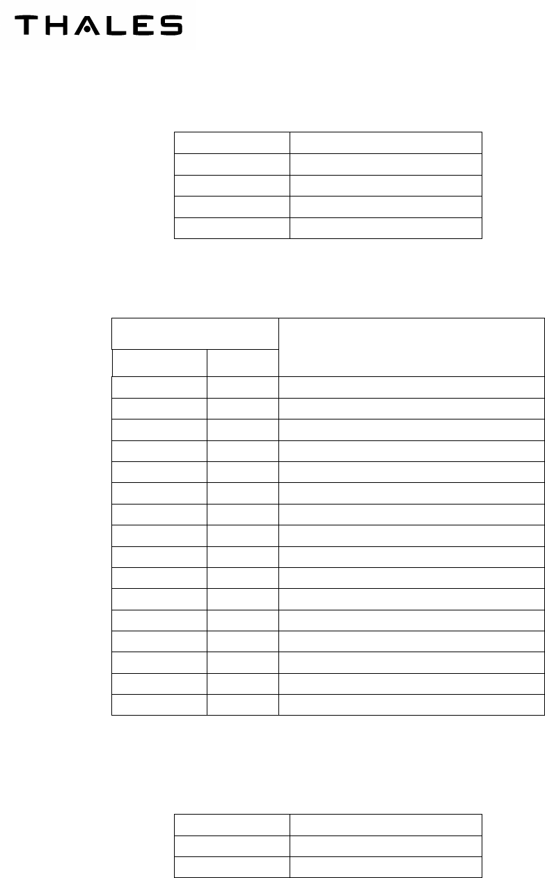
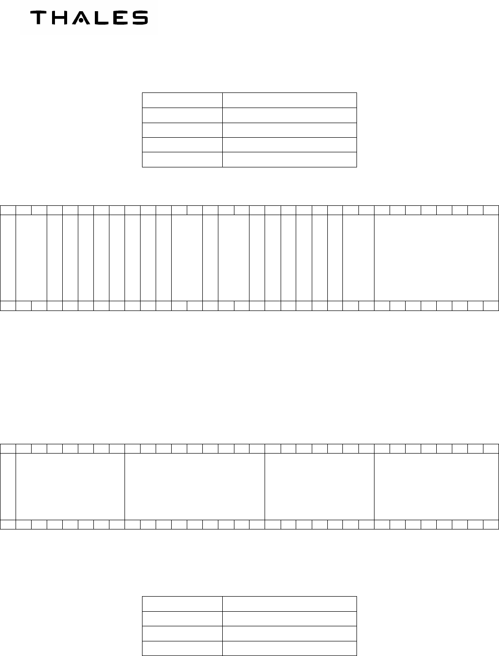
(2) DATA WORD ORGANIZATION
(a) height data word label 164 description :
Label data field:
Bits<8..1> Label value
001 011 10 164
OCT
Source Destination Identifier (SDI) data field :
Bits<10..9> Discrete input “SDI_SEL”
00 Undefined
01 Discrete grounded
10 Discrete open
11 Not used
Functional Test Inhibit (FTI) data:
Bits<11> Discrete input “TST_INH”
0 Discrete open
1 Discrete grounded
THALES Communications
OIM
AHV1600-SYSTEM
Page 108
July 16/09
Height data field:
Bits<29..13>Height value
Height range from 0 ft up to + 5500 ft
LSB value 0.125 ft
Height value coded in 2 complement on 17 bits
(Sign bit<29> - LSB bit<13>)
Status Matrix data field (BNR numeric data word):
Bits<31..30> Validity
00 Failure warning (FW)
01 No Computed Data (NCD)
10 Functional Test (FT)
11 Normal Operation (NO)
32 31
30
29
28
27
26
25
24
23
22
21
20
19
18
17
16
15
14
13
12
11
10
9 8 7 6 5 4 3 2 1
Parity
SM
Sign
Height data value in BNR format coded in two’s complement
LSB
Spare
FTI
SDI
LSB
Label « 164 »
MSB
0 0 0 1 0 1 1 1 0
Figure 108 – ORGANIZATION OF HEIGHT DATA WORD LABEL “164”
(b) Status data word label 271 description
Label data field:
Bits<8..1> Label value
100 111 01 271
OCT
THALES COMMUNICATIONS
OIM
AHV1600-SYSTEM
Page 109
July 16/09
Source Destination Identifier (SDI) data field :
Bits<10..9> Discrete input “SDI_SEL”
00 Undefined
01 Discrete grounded
10 Discrete open
11 Not used
Aircraft Installation delay (AID) data field :
Bits<14..11>
AID_P AID<2..0>
AID Value (fte)
0 111 Reserved
1 111 Configurable input value not authorized
0 110 Configurable input value not authorized
1 110 Reserved
0 101 Configurable input value not authorized
1 101 Reserved
0 100 Reserved
1 100 Configurable input value not authorized
0 011 Configurable input value not authorized
1 011 Reserved
0 010 Reserved
1 010 Configurable input value not authorized
0 001 46.625fte
1 001 Configurable input value not authorized
0 000 Reserved
1 000 Undefined
Functional Test data:
Bits<17> Discrete input “FCT_TST”
0 Discrete grounded
1 Discrete open
THALES Communications
OIM
AHV1600-SYSTEM
Page 110
July 16/09
Test inhibit data:
Bits<18> Discrete input “TST_INH”
0 Discrete grounded
1 Discrete open
Status Matrix data field (discrete data word):
Bits<31..30> Validity
00 Normal Operation (NO)
01 Not used
10 Not used
11 Failure warning (FW)
32 31
30
29
28
27
26
25
24
23
22
21
20
19
18
17
16
15
14
13
12
11
10
9 8 7 6 5 4 3 2 1
Parity
SM
Spare
Spare
Spare
Spare
Spare
Reserved
Reserved
Reserved
Reserved
Reserved
Reserved
TST_INH
FCT_TST
Reserved
Reserved
AID_P
AID2
AID1
AID0
SDI
LSB
Label « 271 »
MSB
0 0 0 0 0 1 0 0 1 1 1 0 1
Figure 109 – ORGANIZATION OF STATUS DATA WORD LABEL “271”
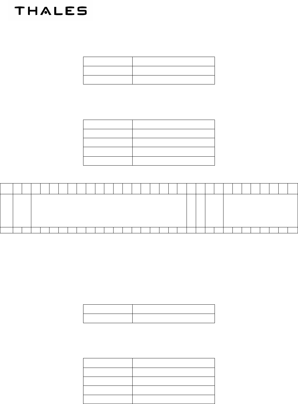
(c) Status data word label 272 description
Label data field:
Bits<8..1> Label value
010 111 01 272
OCT
Source Destination Identifier (SDI) data field :
Bits<10..9> Discrete input “SDI_SEL”
00 Undefined
01 Discrete grounded
10 Discrete open
11 Not used
THALES COMMUNICATIONS
OIM
AHV1600-SYSTEM
Page 111
July 16/09
AHV1600 Transceiver function data field :
Bits<18..17> AU Transceiver function”
00 Search
01 Track
10 No function
11 Reserved
PBIT / IBIT data :
Bits<19> PBIT / IBIT
0 BIT in progress
1 BIT not required
AHV1600 Transceiver mode data field:
Bits<21..20> AU Transceiver mode
00 Reserved
01 Operational
10 Reserved
11 Reserved
Failure data field:
Bit<29..24>
Logic state
Tx antenna Rx antenna PSU I/O CPU Radio
0 Failure
1 No failure
Radio failure: Problem detected on radio board
CPU failure: Problem detected on CPU board
I/O failure: Problem detected on I/O board
PSU failure: Problem detected on PSU board
Rx antenna failure: Impedance on RX antenna fail (50 ohms not detected)
Rx antenna failure: Impedance on TX antenna fail (50 ohms not detected)
THALES Communications
OIM
AHV1600-SYSTEM
Page 112
July 16/09
Status Matrix data field (discrete data word):
Bits<31..30> Validity
00 Normal Operation (NO)
01 Not used
10 Not used
11 Failure warning (FW)
32
31
30
29
28
27
26
25
24
23
22
21
20
19
18
17
16
15
14
13
12
11
10
9 8 7 6 5 4 3 2 1
Parity
SM
Tx_ANT failure
Rx_ANT failure
PSU failure
I/O failure
CPU failure
Radio failure
Spare
Spare
AU Transceiver mode
PBIT / IBIT
AU Transceiver function
Reserved
Reserved
Reserved
Reserved
Reserved
Spare
SDI
LSB
Label « 272 »
MSB
0 0 0 0 1 0 1 1 1 0 1
Figure 110 – ORGANIZATION OF STATUS DATA WORD LABEL “272"
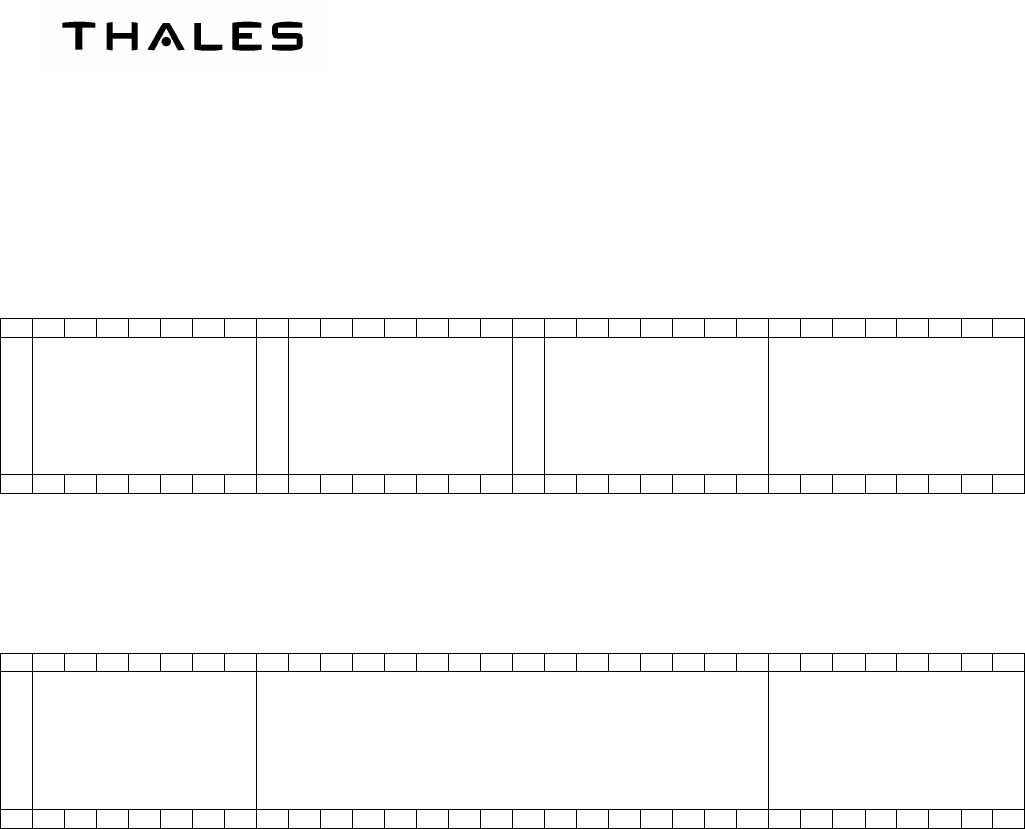
(d) Status data word label 371 description
Several words label “371” are required to transmit the equipment identifier data. These words
label “371” are encapsulated by the “STX” and “EOT” words label “371” to form the global
transmission of the equipment identifier data.
32
31
30
29
28
27
26
25
24
23
22
21
20
19
18
17
16
15
14
13
12
11
10
9 8 7 6 5 4 3 2 1
Parity
STX Spare
MSB
Block Word Count
LSB
LSB
Label « 371 »
MSB
0 0 0 0 0 0 1 0 0 0 0 0 0 0 0 0 0 X X X X X X X 1 0 0 1 1 1 1 1
Figure 111 – ORGANIZATION OF FIRST EQUIPMENT IDENTIFIER DATA WORD LABEL “371”
“Name” data field defined as per three characters:
Name> Discrete input “SDI_SEL”
RA Undefined
RA1 Discrete grounded
RA2 Discrete open
THALES COMMUNICATIONS
OIM
AHV1600-SYSTEM
Page 113
July 16/09
“Part Number” data field defined as per ten characters. e.g. “61778974AC”
“Serial Number” data field defined as all characters from Part Number plus five number char-
acters. e.g. “61778974AC11111”
32
31
30
29
28
27
26
25
24
23
22
21
20
19
18
17
16
15
14
13
12
11
10
9 8 7 6 5 4 3 2 1
Parity
MSB
Character = 3
LSB
Spare
MSB
Character = 2
LSB
Spare
MSB
Character = 1
LSB
LSB
Label « 371 »
MSB
1 0 0 1 1 1 1 1
Figure 112 – ORGANIZATION OF INTERMEDIATE EQUIPMENT IDENTIFIER DATA WORD LABEL “371”
The last equipment identifier data word label “371” shall indicate the end of transmission of
equipment identifier data by transmitting the “EOT” character.
32
31
30
29
28
27
26
25
24
23
22
21
20
19
18
17
16
15
14
13
12
11
10
9 8 7 6 5 4 3 2 1
Parity
EOT Spare
LSB
Label « 371 »
MSB
0 0 0 0 0 1 0 0 0 0 0 0 0 0 0 0 0 0 0 0 0 0 0 0 1 0 0 1 1 1 1 1
Figure 113 – ORGANIZATION OF LAST EQUIPMENT IDENTIFIER DATA WORD LABEL “371”
THALES Communications
OIM
AHV1600-SYSTEM
Page 114
July 16/09
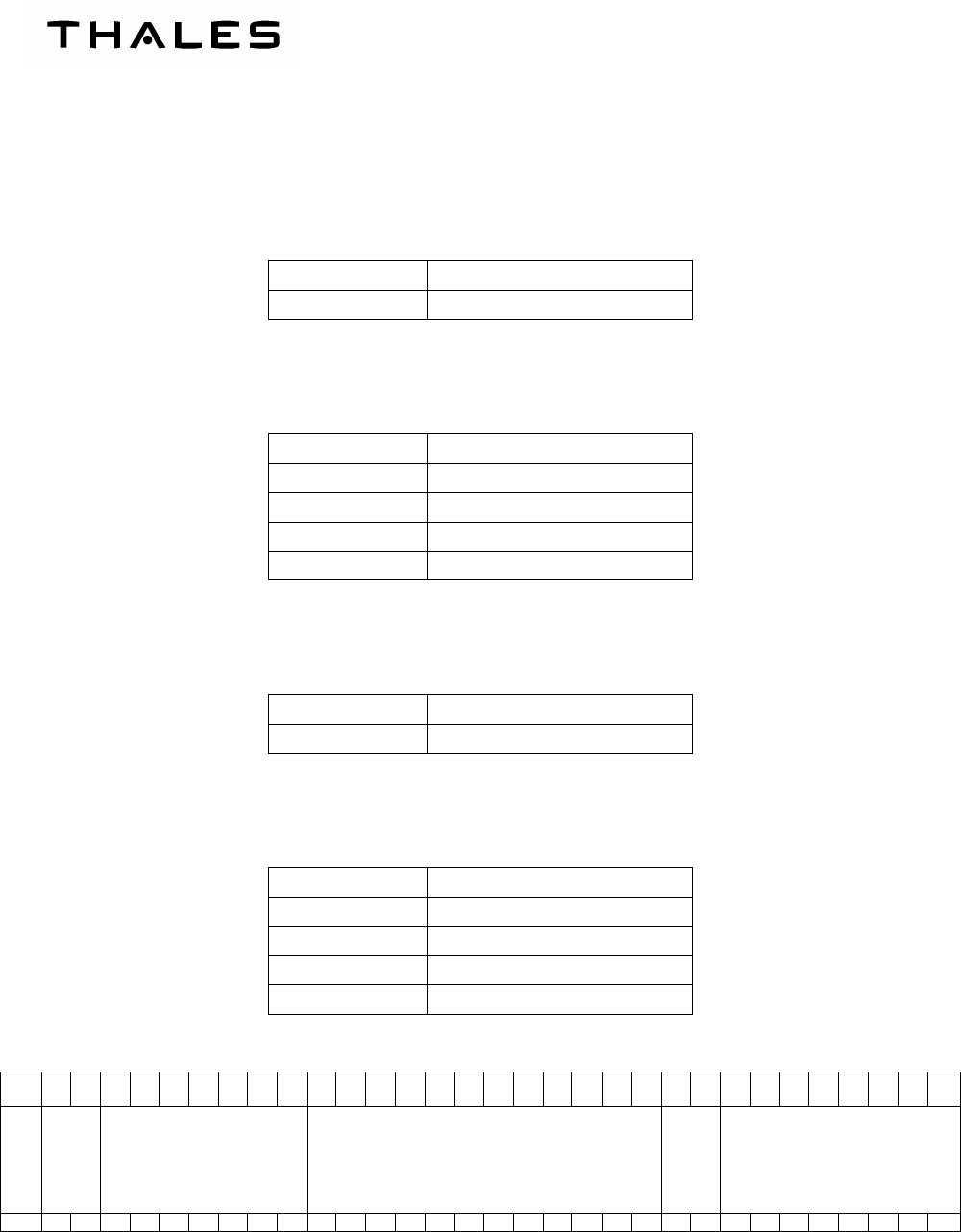
(e) Height data word label 377 description
Label data field:
Bits<8..1> Label value
111 111 11 377
OCT
Source Destination Identifier (SDI) data field :
Bits<10..9> Discrete input “SDI_SEL”
00 Undefined
01 Discrete grounded
10 Discrete open
11 Not used
Equipment identification data field:
Bits<22..11> Equipement identification
111 111 11 007
HEX
Status Matrix data field (discrete data word):
Bits<31..30> Validity
00 Normal Operation (NO)
01 Not used
10 Not used
11 Failure warning (FW)
32 31
30
29
28
27
26
25
24
23
22
21
20
19
18
17
16
15
14
13
12
11
10
9 8 7 6 5 4 3 2 1
Parity
SM
No data
MSB
Equipment Identification Code
LSB
SDI
LSB
Label « 377 »
MSB
0 0 0 0 0 0 0 0 0 0 0 0 0 0 0 0 1 1 1 1 1 1 1 1 1 1 1
Figure 114 – ORGANIZATION OF STATUS DATA WORD LABEL “377"
THALES COMMUNICATIONS
OIM
AHV1600-SYSTEM
Page 115
July 16/09
(f) Height data word label 165 description
Label data field:
Bits<8..1> Label value
101 011 10 165
OCT
Source Destination Identifier (SDI) data field :
Bits<10..9> Discrete input “SDI_SEL”
00 Undefined
01 Discrete grounded
10 Discrete open
11 Not used
Height data field:
Bits<29..11>Height value
Height range from 0 ft up to + 5500 ft
LSB value 0.1 ft
Height value in binary coded decimal on 19 bits
(MSB bit<29> - LSB bit<11>)
Status Matrix data field (BCD numeric data word) :
Bits<31..30> Validity”
00 Normal Operation
01 No computer Data (NCD)
10 Functional Test (FT)
11 Not used

THALES Communications
OIM
AHV1600-SYSTEM
Page 116
July 16/09
32 31
30
29
28
27
26
25
24
23
22
21
20
19
18
17
16
15
14
13
12
11
10
9 8 7 6 5 4 3 2 1
Parity
SM
MSB
Height data value in BCD format
LSB
SDI
LSB
Label « 165 »
MSB
0 0 0 0 0 0 0 0 0 0 0 0 0 0 0 0 1 1 1 1 0 1 0 1 1 1 0
Figure 115 – ORGANIZATION OF HEIGHT DATA WORD LABEL “165"
(3) DISCRETE INPUT SIGNAL
(a) Discrete input signal “FCT_TST”
The AHV1600 transceiver receives the discrete input signal “FCT_TST” from the navigation
and guidance systems to activate its “Built In Test (BIT)” function.
The “FCT_TST” discrete input signal shall initiate the following function of the AHV1600 trans-
ceiver:
− Built In Test function initiated when it is set to low level voltage (discrete grounded).
− Built In Test function not initiated when it is set to high level voltage (discrete open).
To initiate the internal Built In Test function of the AHV1600 transceiver, the minimum time
duration of “FCT_TST” discrete input signal shall be 200ms when measured at 50% level of
the electrical changing voltage.
In the AHV1600 transceiver, the “FCT_TST” discrete input signal shall be in accordance with
the following electrical characteristics:
− Low level voltage ≤ + 3.5 VDC with sink current < 2mA (discrete grounded).
− High level voltage ≥ +15.3 VDC with sink current < 1 mA.
− Maximum level voltage ≤ +32.2 VDC.
when measured to the “M_GND” reference signal.
In the AHV1600 transceiver, the discrete input signal ”FCT_TST” shall be protected against
the indirect effect of lightning.
(b) Discrete input signal “TST_INH”
The AHV1600 transceiver receives the discrete input signal “TST_INH” from the navigation
and guidance systems to inhibit its “Built In Test (BIT)” function.
The “TST_INH” discrete input signal shall inhibit the following function of the AHV1600 trans-
ceiver:

THALES COMMUNICATIONS
OIM
AHV1600-SYSTEM
Page 117
July 16/09
− Initiated Built In Test (IBIT) function inhibited when it is set to low level voltage (dis-
crete grounded).
− Initiated Built In Test (IBIT) function enabled when it is set to high level voltage (dis-
crete open).
In the AHV1600 transceiver, the discrete input signal “TST_INH” shall be in accordance with
the following electrical characteristics:
− Low level voltage ≤ + 3.5 VDC with sink current < 2mA (discrete grounded).
− High level voltage ≥ +15.3 VDC with sink current < 1 mA.
− Maximum level voltage ≤ +32.2 VDC.
when measured to the “M_GND” reference signal.
To inhibit the internal Built In Test function of the AHV1600 transceiver, the minimum time du-
ration of “TST_INH” discrete input signal shall be 200ms when measured at 50% level of the
electrical changing voltage.
In the AHV1600 transceiver, the discrete input signal ”TST_INH” shall be protected against
the indirect effect of lightning.
3. OPERATIONAL INTERFACES
A. POWER SUPPLY
The Transceiver shall be powered with a 28 Vdc ± 5 %.
The voltage transients shall be:
− range 21 V to 32 V for up to 2 ms,
− range 21 V to 38 V for up to 1 ms.
The Transceiver shall be not damaged in unusual conditions:
− 50 V during 50 ms.
B. DIGITAL ARINC429 INTERFACE
This digital interface outputs the altitude information exchanged between the Transceiver and the
navigation computer. There is no ARINC 429 input.
All information is through the Main receptacle J1.
ARINC 429 outputs are differential output signals:
− first ARINC429 output (IRS1 TX HI / IRS1 TX LO),
− second ARINC 429 output (IRS2 TX HI / IRS2 TX LO).*
(1) ELECTRICAL CHARACTERISTICS
(a) When measured to the AID ground reference signal in open circuit
- differential low level voltage : - 10 Vdc ± 1 Vdc
- differential high level voltage : + 10 Vdc ± 1 Vdc

THALES Communications
OIM
AHV1600-SYSTEM
Page 118
July 16/09
- differential null level voltage : 0 Vdc ± 0.5 Vdc
- differential output impedance : 75 Ω ± 5 Ω
(b) When measured to the AID ground reference signal in loaded circuit
- differential low level voltage : between ≥ - 11 Vdc and ≤ - 7.25 Vdc
- differential high level voltage : between ≥ + 7.25 Vdc and ≤ + 11 Vdc
- differential null level voltage : between ≥ - 0.5 Vdc and ≤ + 0.5 Vdc
(2) LIGHTNING PROTECTION
Both differential output signals are protected against the indirect effect of lightning.
(3) TIMING CHARACTERISTICS
- Differential rise time : 10 µs ± 5 µs.
- Differential fall time : 10 µs ± 5 µs.
When measured from 10% to 90% level of the differential changing voltage in open circuit.
C. AID SIGNALS INTERFACE
(1) CONFIGURABLE INPUT SIGNALS
The transceiver receives the configurable input signals “AID_P” and “AID <2..0>” from the Naviga-
tion computer to code the Aircraft Installation Delay. To select the Aircraft Installation Delay, each
dedicated “AID_P” and “AID <2..0>” configurable input signal must be connected as short as possi-
ble to the “AID GROUND” reference signal (or left open).
(2) ELECTRICAL CHARACTERISTICS
- Low level voltage : < + 3.5 Vdc with sink current < 2 mA (logic state 1),
- High-level voltage : > + 15.3 Vdc with sink current < 1 mA (logic state 0),
- Maximum level voltage ≤ + 32.2 Vdc.
When measured to the “M_GND” reference signal.
(3) LIGHTNING PROTECTION
- Configurable input signals are protected against the indirect effect of lightning.
(4) FUNCTIONAL CHARACTERISTICS
- AID length definition: from TX transceiver output to TX antenna through coaxial cable and from
TX antenna to ground through the air and from ground to RX antenna through the air and from
RX antenna to RX input transceiver through coaxial cable
- AID is coded by the “AID_P” and “AID <2..0>” configurable input signals.

THALES COMMUNICATIONS
OIM
AHV1600-SYSTEM
Page 119
July 16/09
(5) PERFORMANCE
•
••
•
Altitude: 5000 ft
•
••
•
Height accuracy: (± 2 ft + 2% of the true height)
D. ENVIRONMENTAL CONDITIONS
DO160E Cat. [(B4)X]BBB[RG]XWFDFSZZAZ[ZC][HF]M[(A4G33)(A3J33)]XXAX
Environmental Condition DO160E DO160E
section Description of conducted test
Temperature and altitude 4 Category B4
Temperature variation 5 Category B
Humidity 6 Category B
Operational shocks and crash safety 7 Category B
Vibration 8 Category R curve G
Explosive atmosphere 9 Not required Category X
Waterproofness 10 Category W
Fluids susceptibility 11 Category F
Sand and dust 12 Category D
Fungus resistance 13 Category F
Salt Fog 14 Category S
Magnetic effect 15 Category Z
Power input 16
Category Z
TCF declares that the AHV1600 Transceiver is able to
withstand momentary power interruption up to 2ms (Test
condition 1 of table 16-3).
Voltage spike 17 Category A
Audio frequency conducted suscepti-
bility – power inputs 18 Category Z
Induced signal susceptibility 19 Category ZC
Radio frequency susceptibility (radi-
ated and conducted) 20 Category H for Conducted Susceptibility
Category F for Radiated Susceptibility
Emission of radio frequency energy 21 Category M
Lightning induced transient suscepti-
bility 22
Pin Injection Tests : Equipment tested to Category
(A4) for power lines and (A3) for interconnecting lines.
Cable Bundle Tests : Equipment tested to Category
(G33) for power lines and (J33) for interconnecting lines.
Lightning direct effects 23 Not required Category X
Icing 24 Not required Category X
Electrostatic discharge 25 Category A
Fire, Flammability 26 Not required Category X

THALES Communications
OIM
AHV1600-SYSTEM
Page 120
July 16/09
E. IN FLIGHT CONDITIONS
In-flight conditions are defined in the following table:
Height range domain From 0 ft to 5000 ft ED-30 height range category B
Horizontal velocity From 0 ft/s to 500 ft/s up to H = 500 ft
From 0 ft/s to 1000 ft/s up to H = 500 ft
Height variation velocity
From 0 ft/s to 20 ft/s up to H = 50 ft
From 0 ft/s to 50 ft/s at 50 ft < H < 500 ft
From 0 ft/s to 500 ft/s at 500 ft < H < 800 ft
From 0 ft/s to 2000 ft/s above H = 800 ft
ED-30 in-flight condition category L/P
Pitch angle Range of 0 to ± 25°(at - 3 dB)
Roll angle Range of 0 to ± 45°(at - 3 dB) ED-30 in-flight condition category L
Radar Altimeter in-flight conditions
4. ANTENNA ANT-140A
A. GENERALITIES ON ANTENNA ANT-140A
The ANT140A antenna is a flat antenna for AHV1600 Radar Altimeter.
The complete installation of the Radar Altimeter requires two identical antennae ANT-140A: one for
transmission (Tx) and one for reception (Rx). These two antennae must be suitably located and
connected by coaxial cables to the transceiver.
The antenna is certified by the DO160B certification.
B. PHYSICAL CHARACTERISTICS
•
••
•
Dimensions: 105.41 x 90.17 x 33 mm,
•
••
•
Weight: 130 ± 20 g,
The antenna is fitted with a female TNC 50 ohms coaxial connector. The connector is protected with
a special cap that must be removed before connecting the antenna.
Two labels equip the antenna: an identification label and an amendment label.
A red ink marking indicates antenna orientation into aircraft.
THALES COMMUNICATIONS
OIM
AHV1600-SYSTEM
Page 121
July 16/09
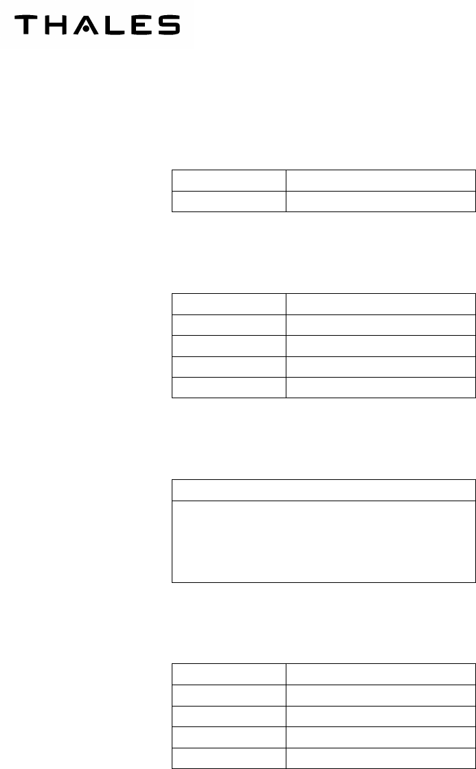
The outside bears the inscription “DO NOT PAINT”, as well as an antenna-positioning symbol.
Figure 117 – ANT-140A OUTER SIDE
A: Antenna-positioning symbol
Figure 116 – ANT-140A INNER SIDE
A
Longitudinal Axle
THALES Communications
OIM
AHV1600-SYSTEM
Page 122
July 16/09
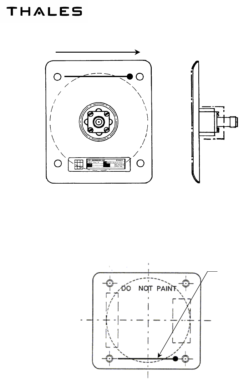
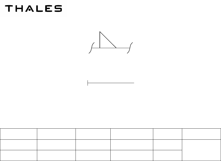
C. FUNCTIONAL CHARACTERISTICS
– Operating frequency band: 4.2 GHz – 4.4 GHz.
– Match:
•
••
•
The return loss on 50 ohms complies with the following diagram
− Isotropic gain:
•
••
•
≥ 7 dBi from 4.2 GHz to 4.4 GHz
− Radiation pattern:
Half-power beamwidth (- 3 dB):
•
••
•
Roll (E-Plane) : 60° ± 7°
•
••
•
Pitch (H-Plane) : 50° ± 5°
NOTE:
The E-plane is perpendicular to the direction of the straight line painted on the external antenna front
face.
The H-plane is parallel to the direction of the straight line.
– Decoupling:
•
••
•
The decoupling value for a distance of 0.4 m between antenna centres is ≥ 72 dB.
– Grounding:
•
••
•
The resistance between connector core and its shielding is < 0.05 ohm.
5. COAXIAL CABLES LENGHT
(1) RECOMMENDED CABLE TYPE ( ACCORDING TO MIL.C 17F SPECIFICATION )
Double screened coaxial is essential to avoid RF leakage.
THALES COMMUNICATIONS
OIM
AHV1600-SYSTEM
Page 123
July 16/09
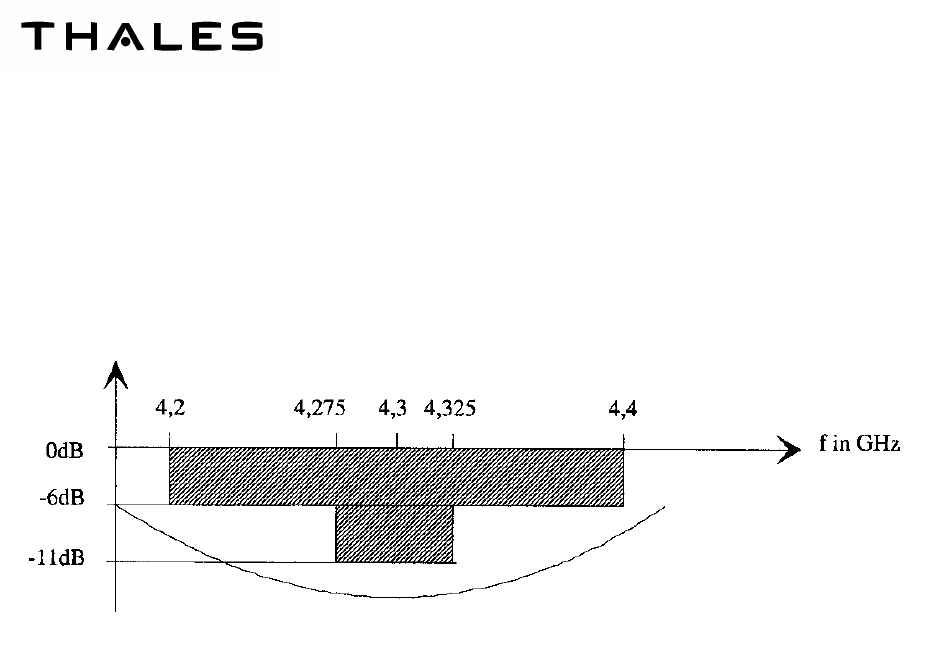
(2) AID DEFINITION
Installation Delay (AID) is the total electrical length from the transceiver transmitting output port to
the aircraft skin, via the transmitting antenna the add to the distance from the antenna to the ground,
add to the distance from ground to receive antenna and back to the transceiver receiving output via
the receiving antenna.
L
1
+ L
2
Electrical length (in feet) of the coaxial cables between the transceiver and transmitting and
receiving antennas respectively.
L
3
+ L
4
Distance (in feet) between transmitting and receiving antennas to the ground when the air-
craft is on the ground
ANT
1
and ANT
2
are the electrical length (in feet) of antennas (1.5 ft per antenna)
The formula for cable mechanical length calculation is:
Le +Lr

THALES COMMUNICATIONS
OIM
AHV1600-SYSTEM
Page 201
July 16/09
INSTALLATION
1. GENERAL CONDITIONS
A. POWER SUPPLY
A nominal voltage of 28 Vdc powers the equipment.
It can nevertheless operate within a DC power supply range of 22 V to 30.3 V.
The absorbed power at 28 V is less than 20 W. It is typically 18 W.
The primary power supply circuit is isolated from the secondary circuit.
B. LOCATION
When selecting a location for equipment and working out the details for installation in the platform,
the objectives should be easy implementation and replacement of the equipment and radar altimeter
as close as possible from the antennae.
C. WATER, SAND, AND DUST TIGHTNESS
Although the equipment is designed to withstand salt spray and a high degree of humidity, it is not
waterproof and precautions should be taken to protect it against trickling or sprayed water (accord-
ing to its specifications).
D. MOUNTING
The AHV1600 Transceiver is fixed on the platform by means of four M6 screws, without any pre-
ferred orientation.
E. INSTALLATION CONDITIONS
The AHV1600 Radar altimeter normal installation conditions are described hereafter:
− Radio Frequency (RF) isolation between the transmission and reception antennae > 75 dB.
− Adaptation of each antenna 50 ohms, over the frequency range (4.2 GHz to 4.4 GHz).
− Gain of each antenna at least 7 dBi and 11 dBi maximum, over the frequency range 4.2 GHz to
4.4 GHz.
− Aperture angles of the antennae are at - 3 dB (with ANT-140A):
•
••
•
in pitch ± 25° ± 2.5°.
•
••
•
in roll ± 30° ± 3.5°.

THALES Communications
OIM
AHV1600-SYSTEM
Page 202
July 16/09
− VSWR 3 to 1 of each antenna (return loss of - 6 dB or less) over the frequency range 4.2 GHz to
4.4 GHz.
− All sides lobes of each antenna must be down 40 dB or better.
− Coax cable 50 ohms double shielded type RG400 or equivalent.
− Losses in both the transmission and reception coaxial cables are of 4 dB minimum and 7 dB
maximum.
− Each antenna shall be grounded on the aircraft frame, on a common metallic grounded structure
for both antennae. The dimension of this structure being at least 15 cm around each antenna.
− No conductive features between antennae or within at least 30 cm around each antenna should
be accepted. Furthermore no conductive features should be seen in a cone of ± 70° centered on
each antenna.
− Avoid antennae to be fitted close to landing gear doors, landing gear or skids.
− Antennae should be preferably installed on a flat and horizontal surface. In any cases two anten-
nae of a given system shall have no more than a 5° angle between their planes. Furthermore,
users have to take into account the fact that tilting any antenna with respect to the aircraft hori-
zontal plane will affect the system performances in terms of capability to withstand aircraft’s atti-
tudes.
− The residual resistance between the structure of the aircraft and the structure of each antenna
(body of the coaxial connector) shall not exceed 2.5 milliohm.
− The residual resistance between the structure of the aircraft and the structure of the transceiver
(body of the coaxial connector, main connector or specific reference mechanical ground pins in
the main connector) shall not exceed 2.5 milliohm.
2. STEP BY STEP TRANSCEIVER INSTALLATION
The AHV1600 Transceiver is fitted with a main MIL-C-38999 series III, 37 contacts connector and two female
MIL-C-39012/TNC coaxial connectors.
Two antennae ANT140A – transmission and reception – are required for the AHV1600 Transceiver. They are
connected by means of two coaxial cables to the AHV1600 Transceiver.
Recommended installation flowcharts:
− control the Transceiver visual aspect,
− secure the Transceiver,
− connect the Main connector,
− connect the coaxial cables.
Warning: before connecting Main connector, be sure 28 Vdc Transceiver supply is inhibited.

THALES COMMUNICATIONS
OIM
AHV1600-SYSTEM
Page 203
July 16/09
A. CHOICE OF ANTENNAE LOCATION
− Choose the location of the antennae carefully. On it will depend the operation of the Trans-
ceiver in all flight configurations.
− Antennae are generally mounted:
• Under the fuselage.
• Such that the H fields are collinear - this configuration corresponds to maximum decoupling
between antennae. The antennae centre line should be preferably parallel to the aircraft
Fore and AFT axis.
• Along a plane parallel to the ground for a normal aircraft flight attitude; if it is not possible to
mount the antennae horizontally, a maximum angle of 5 degrees may be tolerated.
CAUTION: Pitch and roll performances may be degraded for angles exceeding this figure.
• At a location that is preferably perfectly clear of any obstacles in order to avoid hindrance of
the Transceiver by fixed obstacles (landing gear, fuel tanks, other antennae).
• The distance between antennae should be chosen on the basis of two criteria:
− Sufficiently large distance to ensure proper decoupling.
− Sufficiently small distance to ensure proper overlapping of radiation lobes for the mini-
mum height of the antennae above the ground (touchdown or parking position).
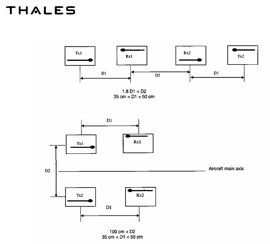
• The distance between antennae should be the following (see Figure 201).
THALES Communications
OIM
AHV1600-SYSTEM
Page 204
July 16/09
B. ANTENNA MOUNTING
Antennae must be flush-mounted, from below, in the lower part of the aircraft fuselage.
Antennae connectors must imperatively face:
− forwards for the front antenna,
− rearwards for the rear antenna.
Each antenna bears a red ink marking to indicate assembly orientation into aircraft.
Figure 201 – ANT-140A – ANTENNAE SEPARATION AND ORIENTATION

THALES COMMUNICATIONS
OIM
AHV1600-SYSTEM
Page 205
July 16/09
C. CONNECTION
The electrical connection for operational use of each antenna is made by means of a single coaxial
connector.
Type of connector mounted on antenna: 50 ohm female coaxial type TNC connector conforming to
specification MIL-C-39012.
3. VERIFICATION
When the AHV1600 Transceiver is installed, a verification of the operation must be done using the PBIT. This
verification must be done in operational conditions.
A. GROUND TESTS
- Prior to install the transceiver, check all interfering for continuity and isolation,
- Install and connect the transceiver,
- Energise the equipment and check that the ARINC output message contains an altitude close to
0ft. Antenna to ground distance may differ in parked situation from the touch down, so this test
altitude may vary slightly around 0 ft,
- Proceed to Functional Test, the ARINC output message shall contain an altitude of 0 ft exactly,
- Check that the coupling to other systems is correct.
B. IN FLIGHT TESTS
- Sensitivity versus altitude: check that the “loss track” altitude of the radio altimeter is greater than
5000 ft (No Computed Data indication on ARINC output message),
- Sensitivity versus attitude: Check that the track is not loss for ROLL and PITCH angles as de-
fined by the half power antennae beamwidth.
- Immunity from track to landing gear down and the helicopter structure: when flying at an altitude
higher than 1000 ft, impose the Functional Test mode. At release of the Functional Test, check
that the track mode is recovered and the transceiver outputs a correct altitude different of 0 ft.
- 0 ft accuracy: at touch down landing, check that the radio altimeter indicates 0 ft.
4. FUNCTIONAL CONNECTIONS WITH RELATED EQUIPMENT
A. INTERFACES CONNECTIONS
The following table displays the connector labels, the function, and the connector reference for all
connectors used for the AHV1600 transceiver.
THALES Communications
OIM
AHV1600-SYSTEM
Page 206
July 16/09
CONNECTOR
LABEL FUNCTION CONNECTOR REFERENCE MATING CONNEC-
TOR REFERENCE
J1 Main connector MIL C- 38999 / MS27468 T 15 B-35 PN
(*)
MT934-T15B35P-
M112
J2 To Antenna TX MIL C 39012
34MMBX-TNC-50-
1/1-2-NE
J3 To Antenna RX MIL C 39012
34MMBX-TNC-50-
1/1-2-NE
(*)
Note: The MIL reference designates a connector including the main external characteristics:
- 37 pins,
- Shell size 15,
- Drab olive green finish,
- Male contacts,
- Normal polarization.
B. GROUNDING AND BONDING
The bottom part of the chassis is used as mechanical and electrical contact with the aircraft fuse-
lage.
Figure 202 shows the surfaces providing bonding contact between the Transceiver chassis and the
platform structure.
Nota : All dimensions are in mm.
Figure 202 – SURFACES BONDING CONTACT OUTLINES
1
6
.
5
3
5
.
4
9
2
1
3
.
5
13.
5
5
R
5
.
7
5
1
8
.9
9
2
4
5
°

THALES COMMUNICATIONS
OIM
AHV1600-SYSTEM
Page 207
July 16/09
C. COOLING OF THE EQUIPMENT
The AHV1600 on platform installation must take into account that heat dissipation for the Trans-
ceiver is partially accomplished through natural convection requiring a minimum space between the
Transceiver and the next equipment of 10 mm.
The remained part of the heat is dissipated by conduction between the bottom part of the Trans-
ceiver chassis and the platform frame. The maximum heat dissipation is 20 watts.
D. HANDLING
No specific tools or support are required to handle or carry the Transceiver due to its small and pre-
hensile dimensions and its lightweight.
The Transceiver is equipped with caps, which are plugged on each I/O connector, and which protect
them from ESD, sand and dust.
5. EQUIPMENT INPUTS / OUTPUTS
A. MAIN CONNECTOR J1
Socket
Contact
Contact
Gauge Input (I) /
Output (O) Signal Name Wire Type Installation Require-
ments
1 22D Reserved
2 22D Reserved
3 22D Reserved
4 22D Reserved
5 22D I FCT_TST Simple see note 4 Discrete input signal
6 22D I TST_INH Simple see note 4 Discrete input signal
7 22D Reserved
8 22D Reserved
9 22D O TX429_HI_1 Twisted/Shielded see
note 2&3 Differential output serial
line
10 22D O TX429_HI_1 Twisted/Shielded see
note 2&3 Differential output serial
line
11 22D Reserved

THALES Communications
OIM
AHV1600-SYSTEM
Page 208
July 16/09
Socket
Contact
Contact
Gauge Input (I) /
Output (O) Signal Name Wire Type Installation Require-
ments
12 22D Reserved
13 22D O TX429_HI_2 Twisted/Shielded see
note 2&3 Differential output serial
line
14 22D O TX429_HI_2 Twisted/Shielded see
note 2&3 Differential output serial
line
15 22D Reserved
16 22D I AID2 Simple (as short as
possible) see note 4 Configurable input signal
17 22D I P28V_1 Twisted see note 1 Power supply input 1
18 22D I P28V_2 Twisted see note 1 Power supply input 2
19 22D I RET28V_2 Twisted see note 1 Power supply return 2
20 22D I AID_P Simple (as short as
possible) see note 4 Configurable input signal
21 22D Reserved
22 22D Reserved
23 22D I AID 0 Simple (as short as
possible) see note 4 Configurable input signal
24 22D I AID 1 Simple (as short as
possible) see note 4 Configurable input signal
25 22D Reserved
26 22D Reserved
27 22D Reserved
28 22D Reserved
29 22D Reserved
30 22D I RET28V_1 Twisted see note 1 Power supply return 1
THALES COMMUNICATIONS
OIM
AHV1600-SYSTEM
Page 209
July 16/09
Socket
Contact
Contact
Gauge Input (I) /
Output (O) Signal Name Wire Type Installation Require-
ments
31 22D Reserved
32 22D Reserved
33 22D O E_GND Electrical reference
ground
34 22D I SDI_SEL Simple (as short as
possible) see note 4 Configurable input signal
35 22D Reserved
36 22D Reserved
37 22D Reserved
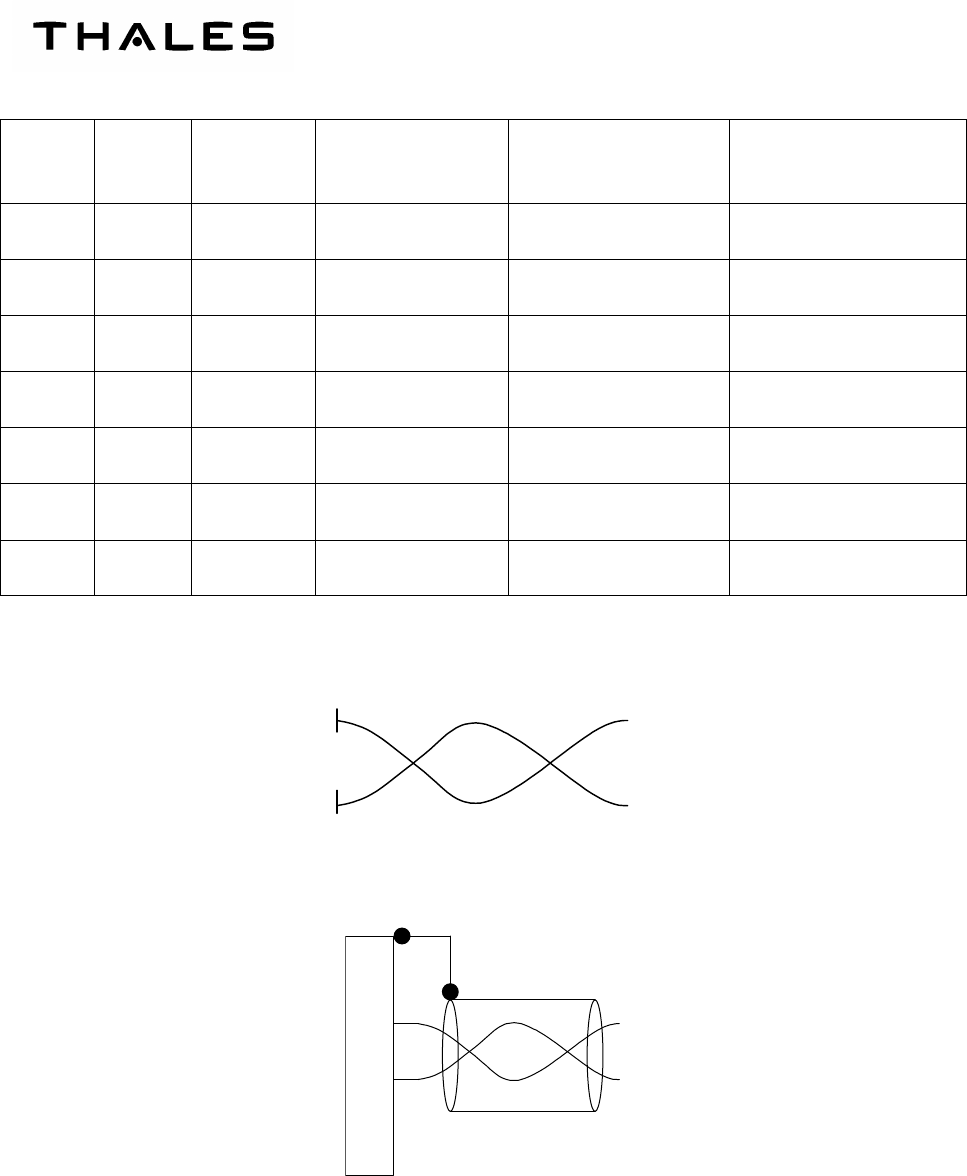
Note 1 :Twisted wire type
Note 2 : Twisted + Shielded wire type (shield shall be terminated at the connector EMI backshell)
Note 3 :ARINC data bus A2 (12.5 Khz)
THALES Communications
OIM
AHV1600-SYSTEM
Page 210
July 16/09
A2
Note 4 : Simple wire type
Note 5: The M_GND reference signal must be connected to the mechanical reference ground of the carrier
B. RX/TX ANTENNA
Connector
Contact Contact Gauge Input (I) / Out-
put (O) Signal Name Wire Type Installation
Requirements
RX TNC I RX Coaxial
cable
TX TNC O TX Coaxial
cable
Length according
to AID selection
THALES COMMUNICATIONS
OIM
AHV1600-SYSTEM
Page 211
July 16/09
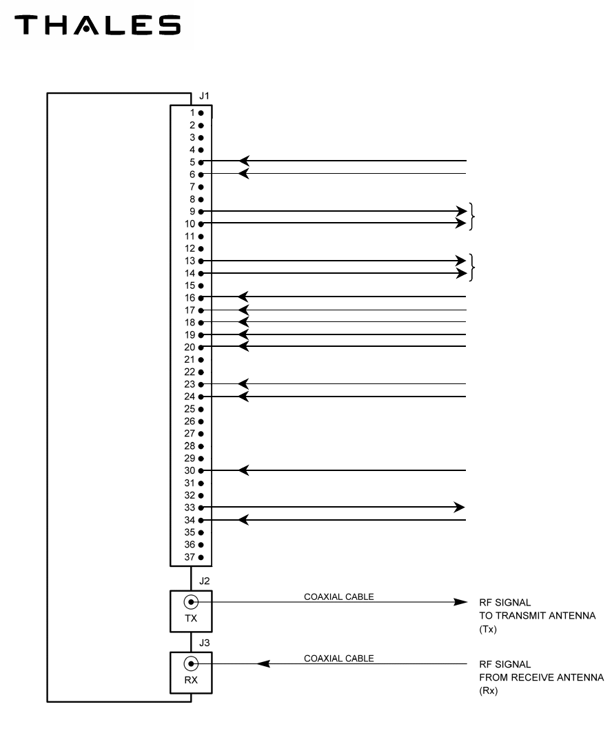
Figure 203 – INTERCONNECTIONS
AHV1600
TRANSCEIVER
INTERNAL
D
E
VICES
TX429_HI_1
TX429_LO_2
TX429_LO_1
FCT_TST
TST_INH
TX429_HI_2
P28V_1
P28V_2
RET28V_2
AID_P
AID0
AID1
RET28V_1
E_GND
SDI_SEL
ARINC 429 LINE
ARINC 429 LINES
+28Vdc (first)
+28Vdc (second)
28Vdc RETURN (second)
28Vdc RETURN (first)
AID2

THALES COMMUNICATIONS
OIM
AHV1600-SYSTEM
Page 301
July 16/09
OPERATION
1. RADAR ALTIMETER ENERGIZATION
The AHV1600 radar altimeter is not provided with an “ON-OFF” switch. The equipment starts operating as
soon as the + 28 VDC power supply is applied by a circuit breaker or other mean located on the helicopter
front panel.
2. FUNCTIONNAL TEST
When the functional test is requested, the system shall outputs a 100 ft test height and functional test is indi-
cated in the status matrix of word labels 164 and 165.
3. NORMAL OPERATING MODE
When on ground or flying in the system range, the radar altimeter shall output the helicopter height above the
ground with the specified accuracy. Alarms shall be out of view.
The status matrix of ARINC 429 words shall indicate the Normal Operation status.
4. OUT OF RANGE OPERATION
When the helicopter is flying outside the system range (above 5000 ft), the radar altimeter shall enters in the
loss of track mode (search mode).
The status matrix of ARINC 429 words shall indicate the No Computed Data status.
5. FAILURE MODE
When a failure is detected by the radar altimeter monitoring, when the helicopter is either on ground or flying,
it is signalled.
The status matrix of ARINC 429 words shall indicate the Failure Warning status.

THALES Communications
OIM
AHV1600-SYSTEM
Page 302
July 16/09
6. DEFAULT OPERATING INSTRUCTIONS
Default Possible cause Corrective action
No output data - Radar altimeter not powered
- Radar altimeter power supply failure
- wiring
- Check circuit breaker
- Change power supply module
- Check wiring
Output data with Failure Warn-
ing status
- Radar altimeter failure - Change transceiver
Output data with No Computed
Data indication
- Loss of system sensitive when heli-
copter on ground or flying in the equip-
ment operating range
- Check antennae installation
- Change transceiver
7. OPERATIONAL LEVEL MAINTENANCE TASK
The Operational level maintenance task consists in removing and replacing the transceiver (LRU) in case of
failure.
A. REMOVING THE TRANSCEIVER
Recommended removing flowchart:
– power-off the transceiver,
– disconnect the three cables from front panel,
– remove the four M6 screws which secure the unit onto the aircraft structure,
– remove the unit.
B. INSTALLING THE SPARE TRANSCEIVER
Refer to INSTALLATION § 2
Before installing the spare Transceiver, ensure the Transceiver location on aircraft structure is clean.