Third Millennium Systems AV90 Access Control Reader, Model AV90 User Manual USERS MANUAL
Third Millennium Systems Ltd. Access Control Reader, Model AV90 USERS MANUAL
Contents
- 1. User Manual
- 2. User manual
- 3. Users Manual
- 4. USERS MANUAL
USERS MANUAL
3millID 9249 S. Broadway Building #200 Suite 826 Highlands Ranch CO 80129
+1 303 475 4972 sales@3millid.com
© 3millID
100-02640-A www.3millid.com
Images shown in this document are for illustrative purposes only. The features, colours, style and appearance may change without notice.
Product Features
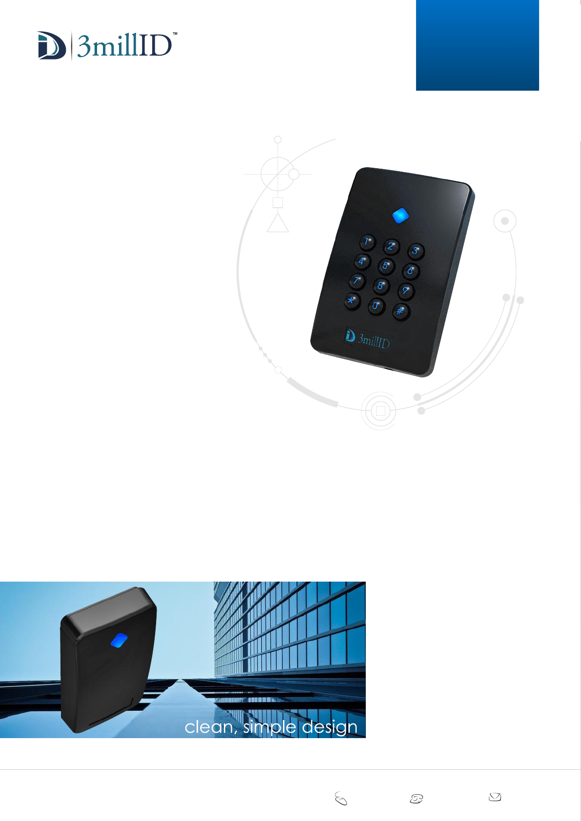
Designed to embrace cutting-edge RFID
technologies in a stylish and innovative
package, this advanced access control reader
offers a refreshing breakthrough in the access
security marketplace. Shaped in a sleek single-
gang style design, with an RGB LED illuminated
keypad, offering ‘prox-and-pin’ security, the reader
may be fixed directly onto a US electrical backbox.
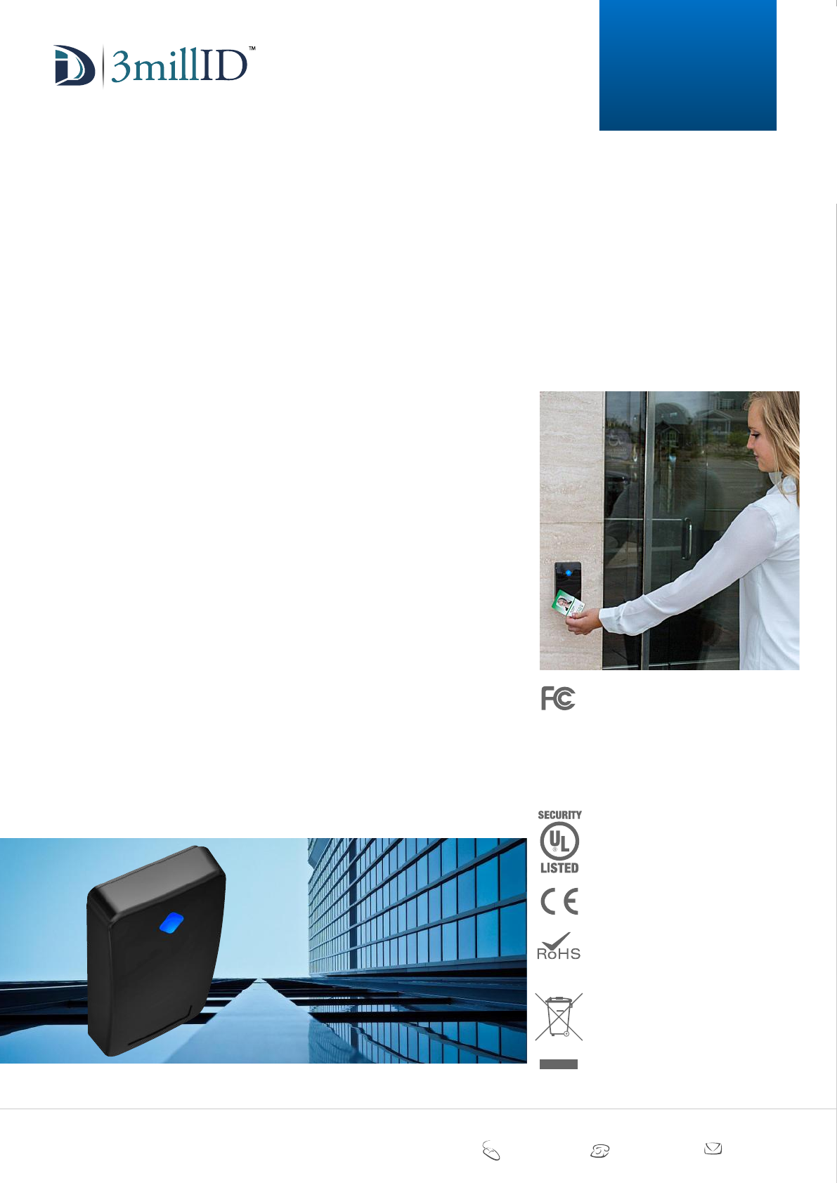
This powerfully secure and innovative reader has a beautifully
clean aesthetic, and a bright RGB LED that can be applied to many
applications such as colour coded access levels, migration status or mood lighting.
The reader housing is moulded using tough polycarbonate plastic, and includes a shadow-line
backplate, a subtle and simple mechanical design feature that makes the reader, when fixed,
appear to float against the wall.
•125KHz Proximity
•13.56MHz Smart Contactless
•Bluetooth LE
•Black textured moulding
•Slim profile
•RGB LED
•Fully encapsulated electronics
•RGB illuminated keypad
•Wide range of output formats
•5 year limited warranty
•Read range up to 10cm (4 inches)
MANUAL
3M
S-Gang
Keypad
style or technology - now you can have both
3millID 9249 S. Broadway Building #200 Suite 826 Highlands Ranch CO 80129
+1 303 475 4972 sales@3millid.com
© 3millID
100-02640-A www.3millid.com
3millID acknowledges all copyrights and registered trademarks used by third parties. No affiliation is implied, or should be
inferred, to the use of any tradename or reference to copyright material.
Any reference to copyright material or registered trademarks within this document is used purely to depict or identify such
material for the purpose of comment, description or comparison, and to assist in the evaluation of products or services
described herein.
No part of this publication may be reproduced or translated into other languages or transmitted into a language used by data
processing machines without the express written consent of 3millID.
E&OE
We do our best to provide accurate and reliable information at the time of publication, but due to continuous developments we
cannot be held responsible for clerical errors, omissions or outdated information, and we reserve the right to amend, alter or
withdraw such information, without notice.
Images shown in this document are for illustrative purposes only. The features, colours, style and appearance may change without notice.
EQUIPMENT
*******
These devices comply with Part 15 of the FCC Rules.
Operation is subject to the following two conditions: (1)
this device may not cause harmful interference, and (2)
this device must accept any interference received,
including interference that may cause undesired
operation.
Any changes or modifications not expressly approved by
the party responsible for compliance could void the user’s
authority to operate the equipment.
These devices contains: FCC ID: TCZ-10103751G1
UTJ-AV90
These RFID proximity readers comply with the essential
requirements and relevant provisions of:
EU Directive 2014/53/EC
.
Together with information provided by suppliers and
subcontractors, these devices comply with the
requirements and relevant provisions of:
EU Directive 2011/65/EC
.
This symbol on the product or on its packaging indicates
that the product must not be disposed of with normal
household waste. Instead, it is your responsibility to
dispose of your waste equipment by arranging to return
it to a designated collection point for the recycling of
waste electrical and electronic equipment. By separating
and recycling your waste equipment at the time of
disposal you will help to conserve natural resources and
ensure that the equipment is recycled in a manner that
protects human health and the environment.
EU Directive 2012/19/EC
SECTION TITLE PAGE
1. Parts List 3
2. Specification 3
3. Installation Guide 4
4. Keypad (programming guide) 5
2
CONTENTS
MANUAL
3M
S-Gang
Keypad
style or technology - now you can have both
3millID 9249 S. Broadway Building #200 Suite 826 Highlands Ranch CO 80129
+1 303 475 4972 sales@3millid.com
© 3millID
100-02640-A www.3millid.com
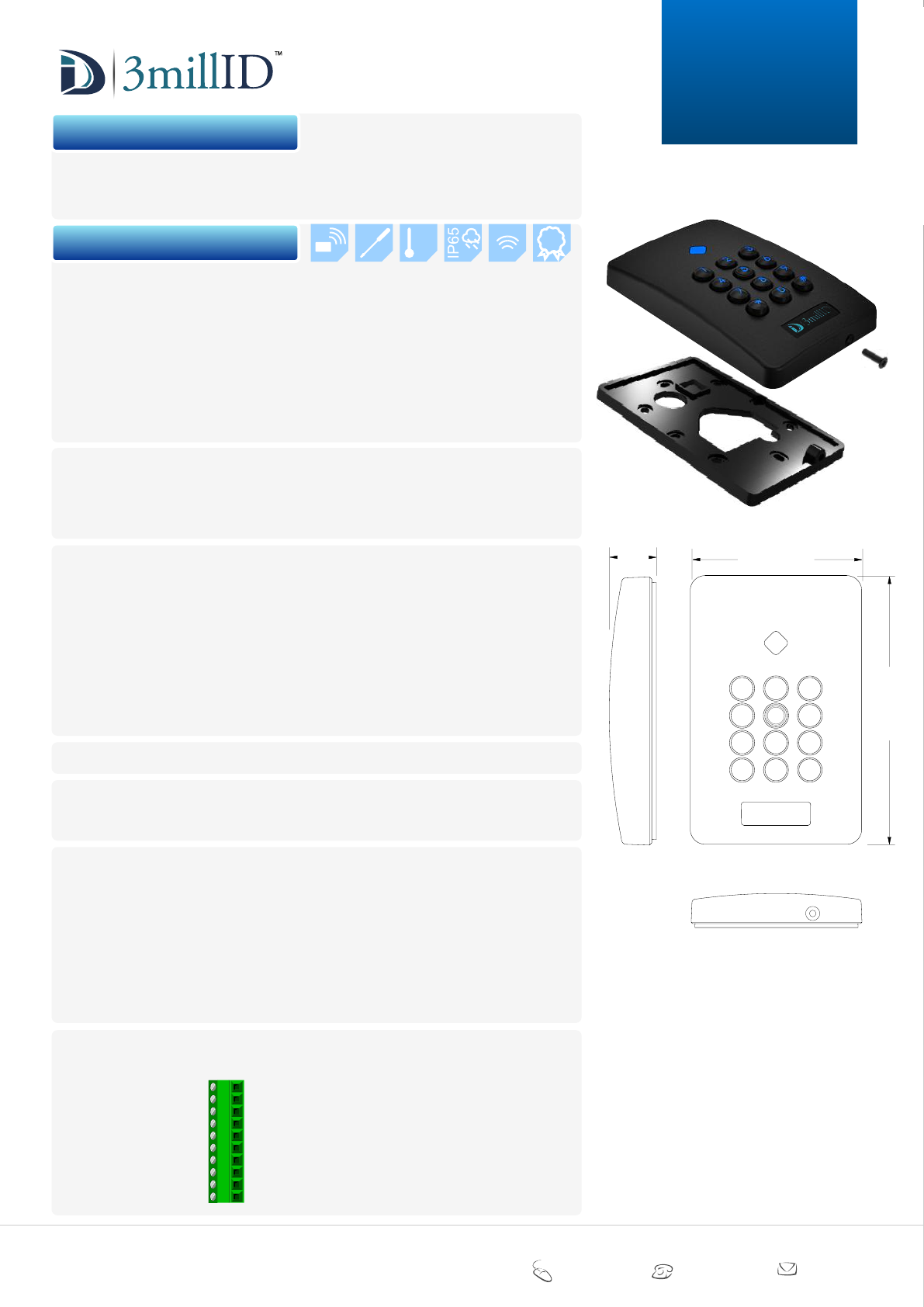
1 x reader MODULE
1 x reader BACKPLATE
1 x 3 x 10mm black cross-head securing screw
10cm
up to
+
-
66
35
C
5yrs
1. parts list
2. specification
performance level for access control
This product complies with the following UL294 Access Control Performance Levels:
Destructive Attack Level I
Line Security Level I
Endurance Level IV
Standby Power Level I
See the UL Listed access control unit controller installation instructions for reader
compatibility.
UL Ref. Number ??????
environmental
Operating Temperature -35°C to +66°C (-31°F to + 151°F)
Humidity 85 ±5% at 30 ±2°C (86 ±3°F)
Ingress Protection IP65 (not evaluated by UL)
Positioning Suitable for INDOOR and OUTDOOR use.
electrical
Power supply Power is to be provided by a UL294 Listed, low-voltage
Class 2 power limited supply or control panel, capable
of 4 hours standby.
Voltage +10Vdc to +16Vdc
Current 135mA typical
Data Voltage Rest >4Vdc / Active <1Vdc
Data Output Wiegand, Clock & Data, Custom Outputs
Indication 1 RGB LED + RGB illuminated keypad
Sounder Integral speaker
dimensions 120mm x 76mm x 21mm (4.7 x 3.0 x 0.8 inches)
polymeric materials
Potting compound UL R/C (QMFZ2)
Mouldings UL746C
wiring Wiring methods shall be in accordance with the
National Electrical Code (ANSI/NFPA70), local
codes, and the authorities having jurisdiction.
Recommended cable BELDEN 953x (or equivalent UL listed) - Wiegand
BELDEN 9502 (or equivalent UL listed) - RS485
All cable and wiring must be Listed and suitable for use.
Cable length Cable length must not exceed 30 metres maximum
(98.5 feet) for UL
Minimum permissible wire size not less than 26 AWG (0.24mm²)
connections
Screw terminal (All readers in this series use this terminal connection)
1 - 0V Supply voltage ground
2 - +Vdc Supply voltage (+10Vdc to +16Vdc)
3 - DATA1/CLK Wiegand or Clock/Data output
4 - DATA0/DAT Wiegand or Clock/Data output
5 - GREEN Green LED control input
6 - RED Red LED control input
7 - Buzzer Buzzer control input
8 - TMPR/CP Tamper or Card Present output
9 - RS485- RS485 Bus
10 - RS485+ RS485 Bus
120mm
4.7 inches
21mm
0.8 inch 76mm
3.0 inches
6
8
0
9
#
4
7
*
5
1 2 3
MANUAL
3M
S-Gang
Keypad
3
3millID 9249 S. Broadway Building #200 Suite 826 Highlands Ranch CO 80129
+1 303 475 4972 sales@3millid.com
© 3millID
100-02640-A www.3millid.com
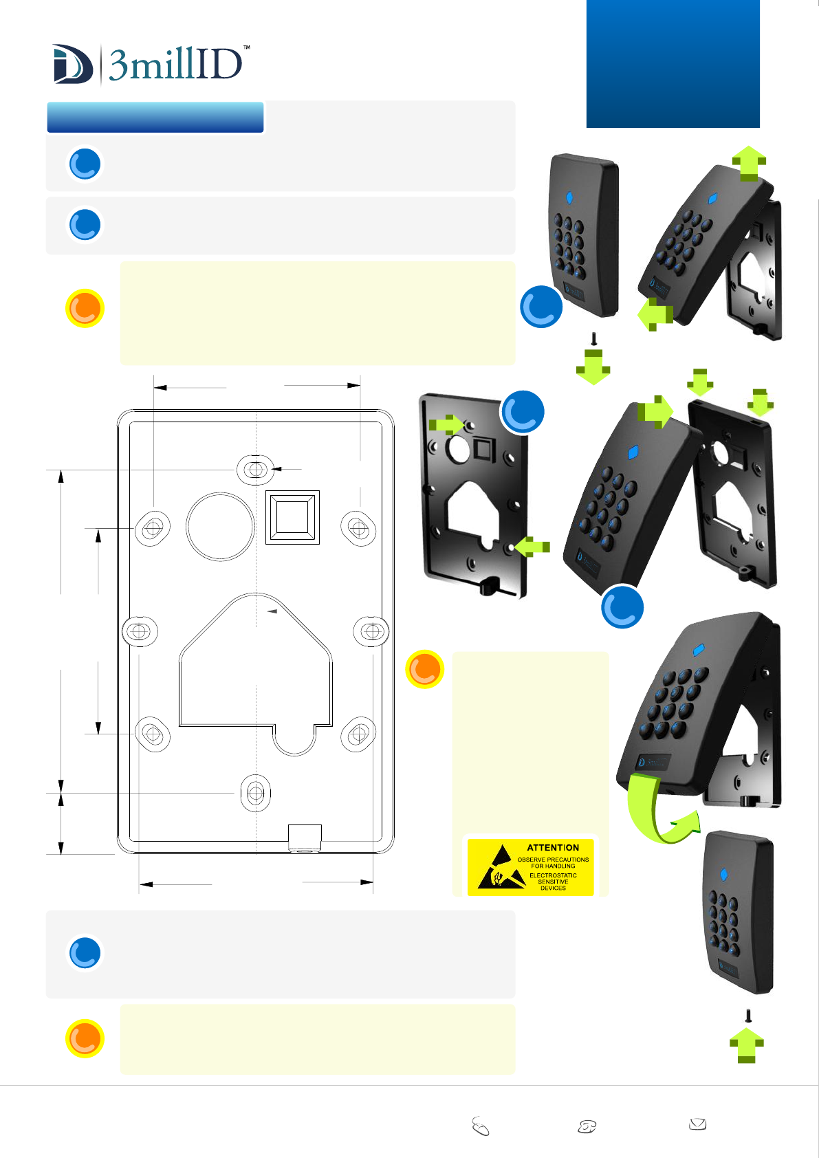
Remove module securement screw. Lever bottom edge of reader module away
from the backplate, and lift up.
Fix reader BACKPLATE to a plain surface finish, using suitable screw fixings
having a diameter no greater than 4mm (0.15 inch).
If printed full scale, you may use the drawing below as a fixing template.
MEASURE and CHECK DIMENSIONS before use.
NOTE:
Mounting this reader on (or near) metal may impair the read range of the unit.
3. installation guide
Fasten the reader module, ensuring the top-edge fixings engage correctly with the
recesses at the top of the backplate. Swing the bottom edge of the module down
and forward until you feel the unit ‘snap’ shut.
Secure the module to the backplate using the M3x10mm screw supplied.
If required, you may opt to use a security screw to the sizes shown here.
Following installation, it is recommended the access control system and control
units are subjected to a maintenance and operational test procedure.
TEST COMPLETE SYSTEM AT LEAST ONCE A YEAR
i
1
2
i
3
1
Once the backplate is
secured, make wire
connections to the reader, in
accordance with the screw
terminal connections shown
on Page 3 of this document
and your control panel
requirements. Ensure the
cable does not impair or
prevent the reader module
being secured.
i
2
3
83.3mm (US)
3.3 inches
60.3mm (UK/EU)
2.4 inches
53.0mm
2.1 inches
53.0mm
2.1 inches
15mm
0.6 inch
centreline
BACKPLATE
Fixing holes - 4mm
maximum diameter.
MANUAL
3M
S-Gang
Keypad
4

3millID 9249 S. Broadway Building #200 Suite 826 Highlands Ranch CO 80129
+1 303 475 4972 sales@3millid.com
© 3millID
100-02640-A www.3millid.com
‘MIFARE’, ‘MIFARE Classic’ and ‘MIFARE DESFire EV1’ are trademarks of NXP B.V.
MANUAL
3M
S-Gang
Keypad
5
- entering programming mode
- set PIN mode (output)
- set audible tone on key press
- set audible tone on card
- set proximity reading
- set LED colour configuration
- set site code embedding
- set LED quiescent colour
6
6
7
7
7
8
8
8
LOG ON
PIN MODE
KEY TONE
CARD TONE
PROX READ
RX00 LED
SITE CODE
RX00 COLOUR
*00
*01
*02
*03
*04
*05
*06
*07
pageKEYPAD SECTION TITLE DESCRIPTION
- set reader to read HID®
- set reader to read EM
- set reader to read CASI
- set reader to read AWID
- set reader to read KANTECH
- set reader to read FARPOINTE
- set reader to read MIFARE®
- set reader to read ENDIAN
- set reader to read DESFire®
RX00 HID
RX00 EM
RX00 CASI
RX00 AWID
RX00 KANTECH
RX00 FARPOINTE
RX80 MIFARE
RX80 ENDIAN
RX90 DESFIRE
*10
*11
*12
*13
*14
*15
*20
*21
*30
- set engineer’s PIN code
- exit configuration mode
12
12
SET PIN
LOG OFF
*98
*99
9
9
9
10
10
10
11
11
11
The following instructions give a step-by-step procedure for accessing the many features
supported by this reader.
4. keypad programming guide
3millID 9249 S. Broadway Building #200 Suite 826 Highlands Ranch CO 80129
+1 303 475 4972 sales@3millid.com
© 3millID
100-02640-A www.3millid.com
MANUAL
3M
S-Gang
Keypad
6
*010#
*011#
*012#
*013#
*014#
*015#
*016#
*017#
*018#
*019#
.....
.....
.....
.....
.....
.....
.....
.....
.....
.....
example
*00nnnn#
LOG-ON
PIN CODES
*00
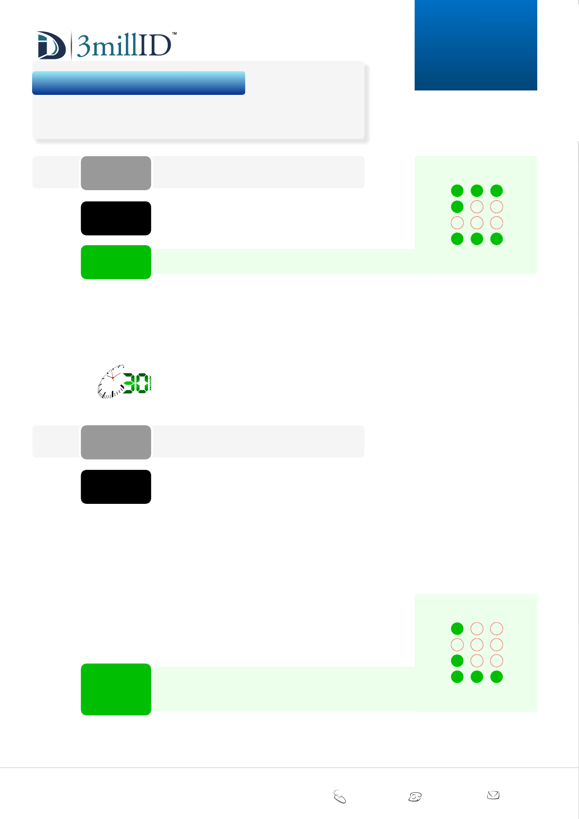
entering ‘PROGRAMMING MODE’
example
Before you can configure the reader you MUST enter
programming mode by using this command. You must enter
the correct four-digit security PIN for the reader.
The factory default PIN = 1234
This programming command allows you to configure how
the reader handles keypad data. The reader is capable of
keypad data output in a number of industry-standard
formats. The following modes are supported:
*010#
*011#
*012#
*013#
*014#
*015#
*016#
*017#
*018#
*019#
DISABLED (NO keypad output)
HID 4-bit WIEGAND (factory default)
Dorado 8-bit WIEGAND (compatible with INDALA)
Mercury 8-bit WEIGAND burst
1 digit CLOCK and DATA
Dorado 8-bit burst
8 digit CLOCK and DATA (buffered)
26-bit WIEGAND (buffered)
32-bit WIEGAND (buffered)
34-bit WIEGAND (buffered)
To set the reader to buffer keystrokes and output them in
the industry-standard 26-bit WIEGAND format, you should
enter: *017# once the reader has been placed into
programming mode.
To place a FACTORY-DEFAULT reader into programming
mode, you must enter: *001234#
After entering programming mode, the reader will time out
after approximately 30 seconds if no keys are pressed for
that duration. Any changes you may have made to values or
settings will be lost.
To change the log-on PIN code, see:
Section *98 on Page 12 of this document.
NOTE:
To exit PROGRAMMING MODE see:
Section *99 on Page 12 of this document.
You must correctly exit this mode to save any changes to
values or settings you may have made.
NOTE:
6
8
0
9
#
4
7
*
5
1 2 3
The following instructions give a step-by-step procedure for accessing the many features
supported by this reader.
4. keypad programming guide
PIN mode
PIN CODES
*01
set PIN mode (output)
*01n#
6
8
0
9
#
4
7
*
5
1 2 3
3millID 9249 S. Broadway Building #200 Suite 826 Highlands Ranch CO 80129
+1 303 475 4972 sales@3millid.com
© 3millID
100-02640-A www.3millid.com
MANUAL
3M
S-Gang
Keypad
7
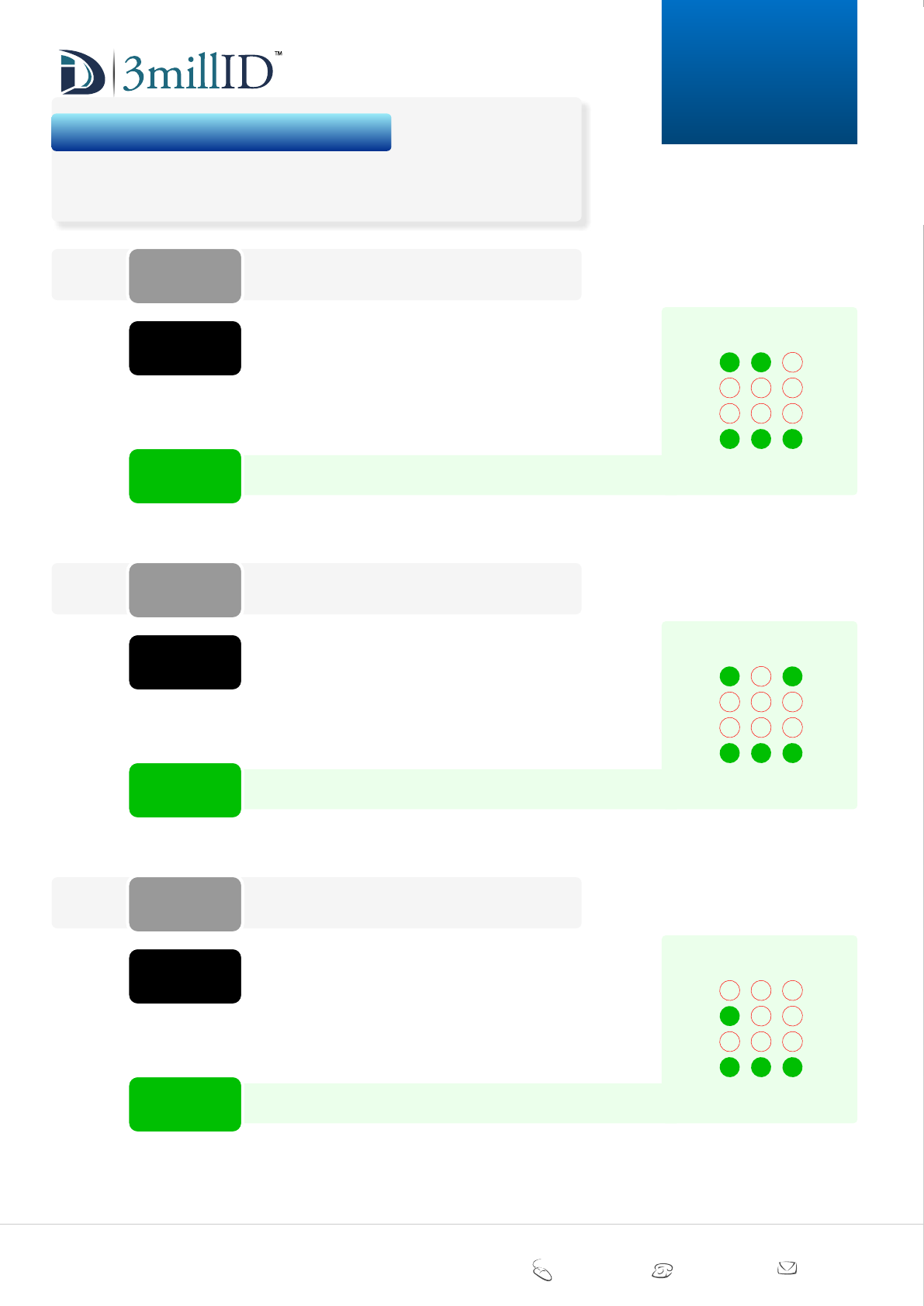
KEY TONE
PIN CODES
*02
set AUDIBLE TONE on KEY PRESS
CARD TONE
PIN CODES
*03
set AUDIBLE TONE on CARD
PROX READ
PIN CODES
*04
set PROXIMITY READING
*020#
*021#
.....
.....
*02n#
example
*030#
*031#
.....
.....
*03n#
example
*040#
*041#
.....
.....
*04n#
example
The following instructions give a step-by-step procedure for accessing the many features
supported by this reader.
4. keypad programming guide
DISABLE (NO audio tone) (factory default)
ENABLE (audible tone on PIN entry)
To ENABLE the buzzer, enter: *021# once the reader has
been placed into programming mode.
During the entry of a buffered PIN you have the option of
making the reader issue a confirmation beep or an error
(triple-beep) on entering the PIN.
6
8
0
9
#
4
7
*
5
1 2 3
During the entry of a buffered PIN you have the option of
making the reader issue a confirmation beep or an error
(triple-beep) on presenting a CARD.
To ENABLE audio tone, enter: *031# once the reader has
been placed into programming mode.
DISABLE (NO audio tone) (factory default)
ENABLE (audible tone on presenting a card)
6
8
0
9
#
4
7
*
5
1 2 3
This programming command allows you to disable
transmission of the proximity card data from the reader.
The reader will still beep to indicate that it has read the card.
To DISABLE transmission of the card data, enter: *040#
once the reader has been placed into programming mode.
DISABLE (data will NOT be sent)
ENABLE (data WILL be sent) (factory default)
6
8
0
9
#
4
7
*
5
1 2 3
3millID 9249 S. Broadway Building #200 Suite 826 Highlands Ranch CO 80129
+1 303 475 4972 sales@3millid.com
© 3millID
100-02640-A www.3millid.com
MANUAL
3M
S-Gang
Keypad
8
*05n#
example
*050#
*051#
*052#
*053#
*054#
.....
.....
.....
.....
.....
*06nnnnn#
example
*07n#
example
*070#
*071#
*072#
*073#
*074#
*075#
*076#
*077#
.....
.....
.....
.....
.....
.....
.....
.....
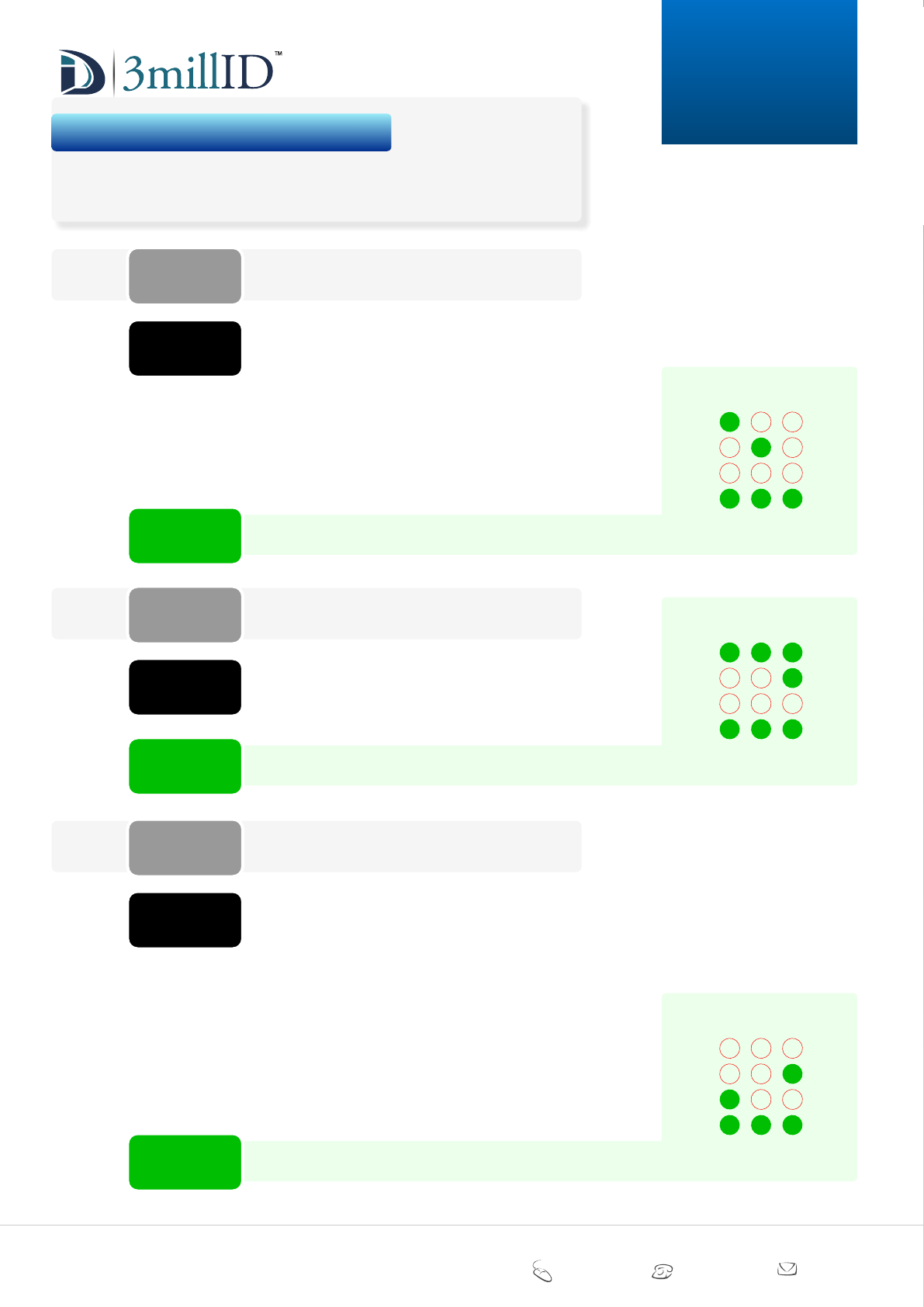
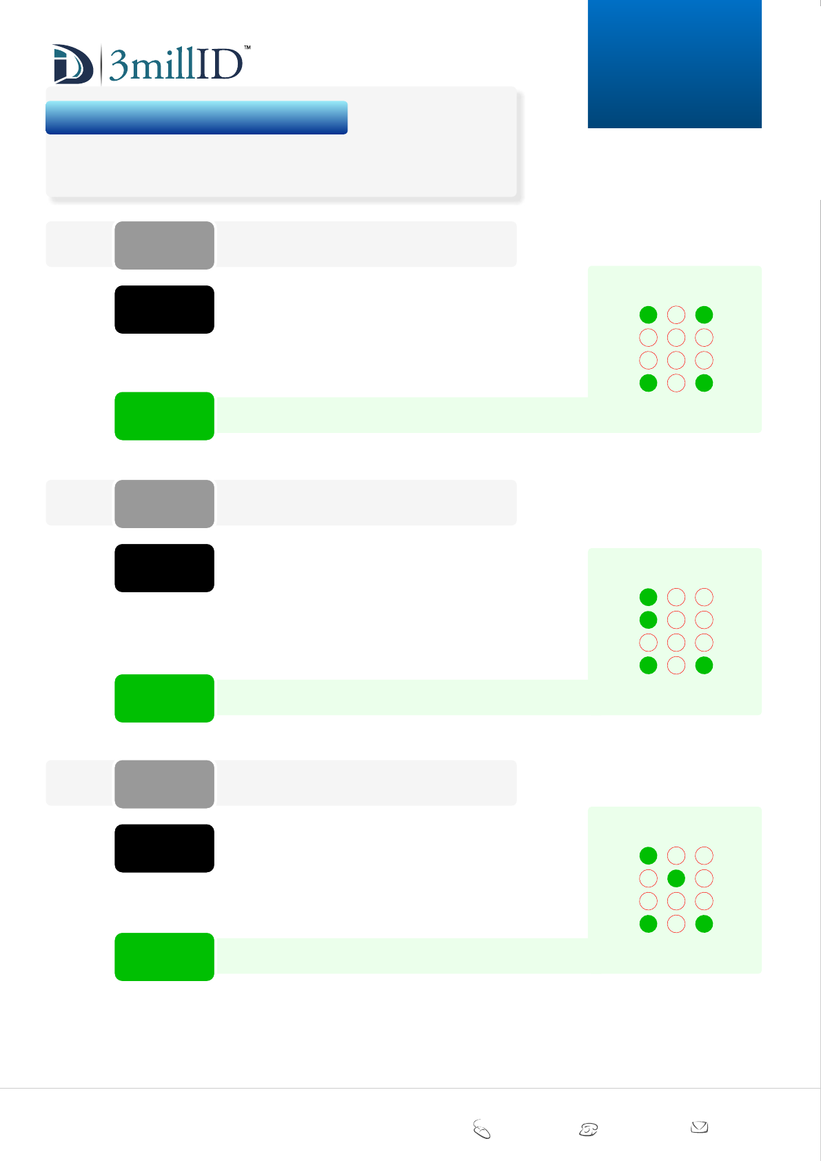
RX00 LED
PIN CODES
*05
set LED COLOUR CONFIGURATION
SITE CODE
PIN CODES
*06
set SITE CODE EMBEDDING
RX00 COLOUR
PIN CODES
*07
set LED QUIESCENT COLOUR
To set RX Demo enter: *051# once the reader has been
placed into programming mode.
The LED may be configured to the following modes:
6
8
0
9
#
4
7
*
5
1 2 3
The following instructions give a step-by-step procedure for accessing the many features
supported by this reader.
4. keypad programming guide
RX standard LED configuration
RX Demo
RX buzzer
RX AWE (excluded from documentation)
RX MPS (excluded from documentation)
This option allows the SITE CODE number to be combined
with the card number read from the card and sent as the
complete card info’ message. The unit accepts site codes
from 0 to 65535 - however the maximum valid value
depends on the output format.
To embed SITE CODE ‘123’ enter: *0600123# once the
reader has been placed into programming mode.
6
8
0
9
#
4
7
*
5
1 2 3
The LED may be configured to the following standard
colours.
To set the LED to TURQUOISE enter: *076# once the
reader has been placed into programming mode.
6
8
0
9
#
4
7
*
5
1 2 3
Blue
Magenta
Yellow
Orange
Red
White
Turquoise
OFF (LED disabled when in idle mode)
3millID 9249 S. Broadway Building #200 Suite 826 Highlands Ranch CO 80129
+1 303 475 4972 sales@3millid.com
© 3millID
100-02640-A www.3millid.com
MANUAL
3M
S-Gang
Keypad
9
*10n#
example
*100#
*101#
*102#
.....
.....
.....
*11n#
example
*110#
*111#
*112#
*113#
*114#
.....
.....
.....
.....
.....
*12n#
example
*120#
*121#
*122#
*123#
*124#
.....
.....
.....
.....
.....
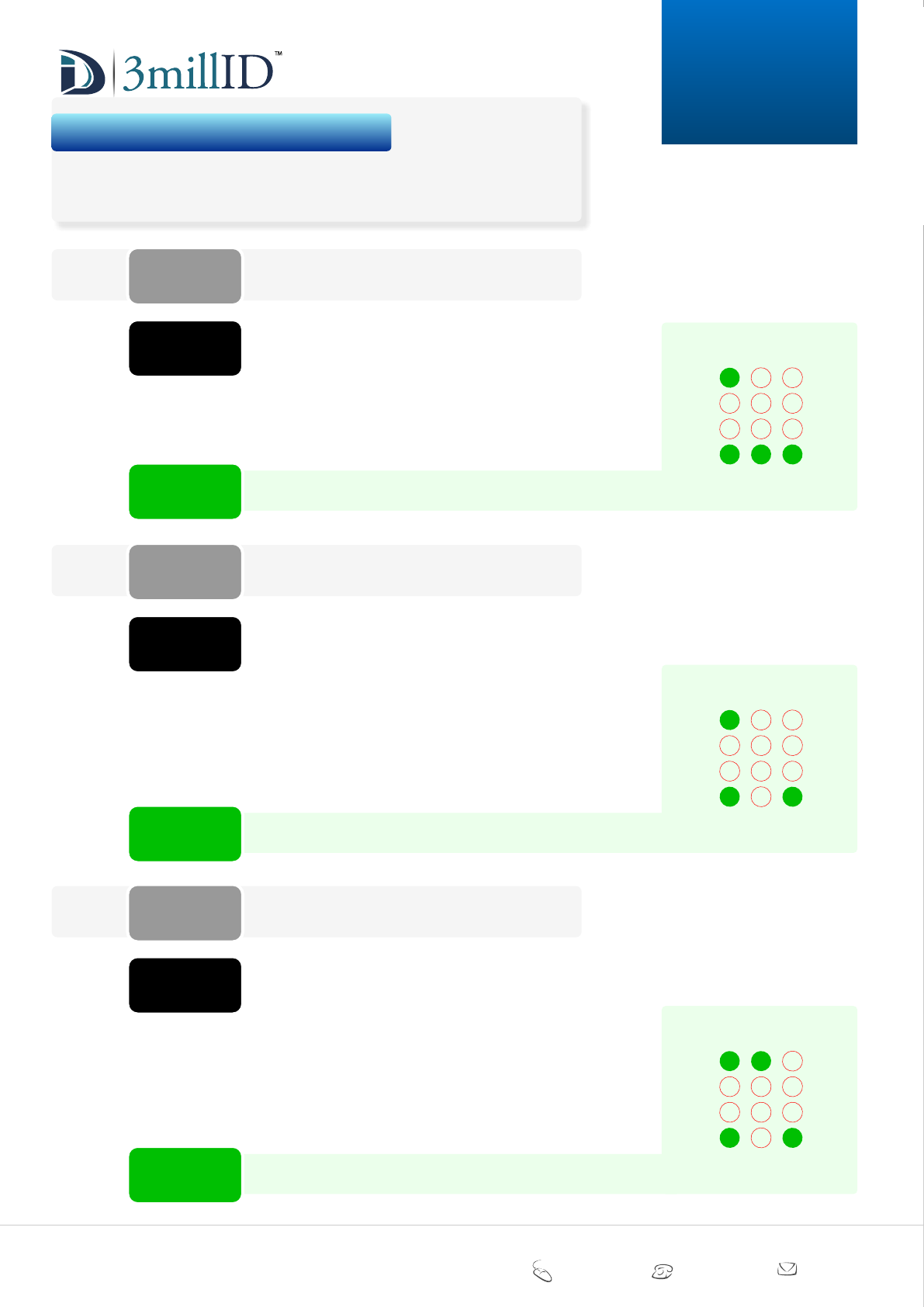
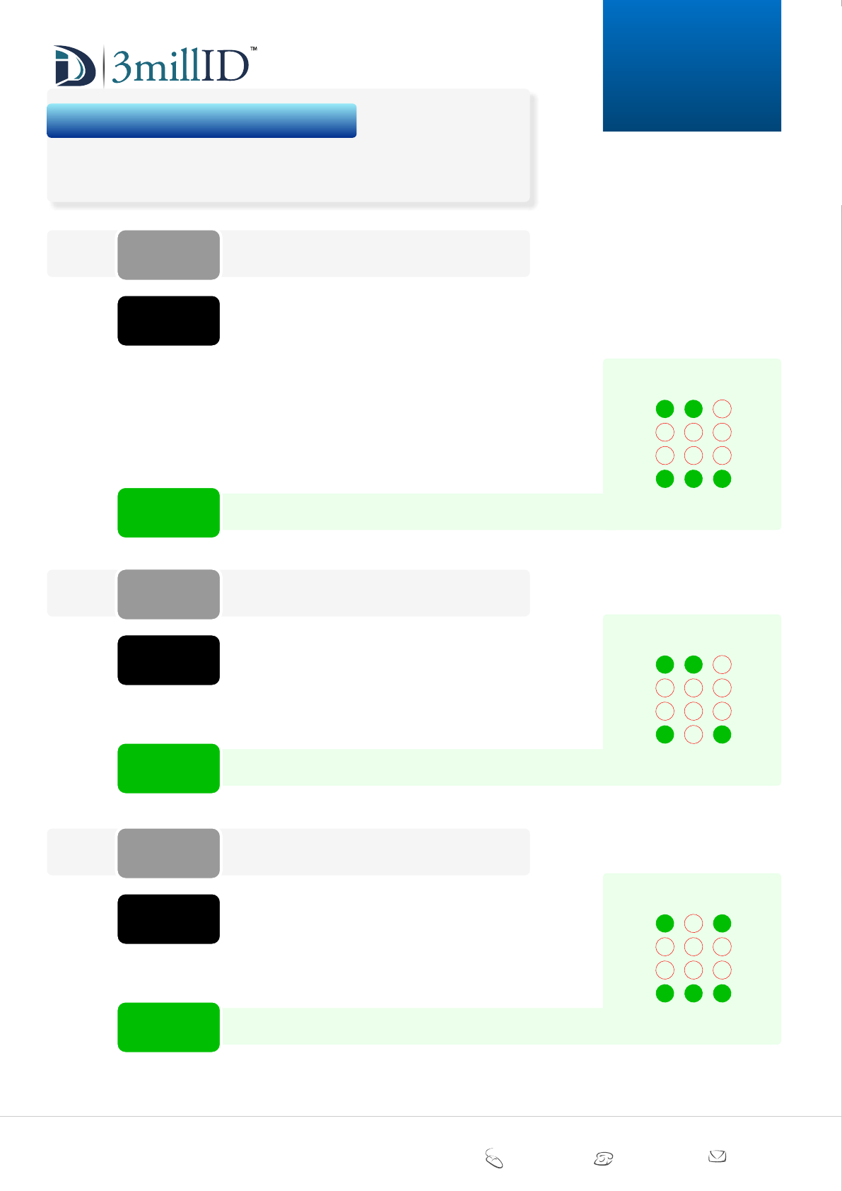
RX00 HID
PIN CODES
*10
set reader to read ‘HID®’
RX00 EM
PIN CODES
*11
set reader to read ‘EM’
RX00 CASI
PIN CODES
*12
set reader to read ‘CASI’
The following instructions give a step-by-step procedure for accessing the many features
supported by this reader.
4. keypad programming guide
To set WIEGAND Pass Through enter: *101# once the
reader has been placed into programming mode.
Configure reader to read ‘HID®’ proximity cards.
6
8
0
9
#
4
7
*
5
1 2 3
DISABLE function
WIEGAND Pass Through
Clock and Data
To set 26-bit WIEGAND enter: *111# once the reader has
been placed into programming mode.
Configure reader to read ‘EM’ proximity cards.
6
8
0
9
#
4
7
*
5
1 2 3
DISABLE function
26-bit WIEGAND
34-bit WIEGAND
42-bit WIEGAND
Clock and Data
To set 4001 40-bit WIEGAND enter: *121# once the
reader has been placed into programming mode.
Configure reader to read ‘CASI’ proximity cards.
6
8
0
9
#
4
7
*
5
1 2 3
DISABLE function
4001 40-bit WIEGAND
4002 40-bit WIEGAND
Extended 4001 40-bit WIEGAND
Extended 4002 40-bit WIEGAND
3millID 9249 S. Broadway Building #200 Suite 826 Highlands Ranch CO 80129
+1 303 475 4972 sales@3millid.com
© 3millID
100-02640-A www.3millid.com
MANUAL
3M
S-Gang
Keypad
10
RX00 AWID
PIN CODES
*13
set reader to read ‘AWID’
RX00 KANTECH
PIN CODES
*14
set reader to read ‘KANTECH’
RX00 FARPOINTE
PIN CODES
*15
set reader to read ‘FARPOINTE’
*13n#
example
*130#
*131#
.....
.....
*14n#
example
*140#
*141#
*142#
.....
.....
.....
*15n#
example
*150#
*151#
.....
.....
The following instructions give a step-by-step procedure for accessing the many features
supported by this reader.
4. keypad programming guide
To set ENABLE ‘AWID’ function, enter: *131# once the
reader has been placed into programming mode.
Configure reader to read ‘AWID’ proximity cards.
6
8
0
9
#
4
7
*
5
1 2 3
DISABLE function
ENABLE function
To set KANTECH 26-bit Wiegand enter: *141# once the
reader has been placed into programming mode.
Configure reader to read ‘KANTECH®’ proximity cards.
6
8
0
9
#
4
7
*
5
1 2 3
DISABLE function
26-bit WIEGAND
39-bit XSF WIEGAND
To enable Farpointe enter: *151# once the reader has
been placed into programming mode.
Configure reader to read ‘FARPOINTE®’ proximity cards.
6
8
0
9
#
4
7
*
5
1 2 3
DISABLE function
ENABLE function
3millID 9249 S. Broadway Building #200 Suite 826 Highlands Ranch CO 80129
+1 303 475 4972 sales@3millid.com
© 3millID
100-02640-A www.3millid.com
MANUAL
3M
S-Gang
Keypad
11
RX80 MIFARE
PIN CODES
*20
set reader to read ‘MIFARE®’
RX80 ENDIAN
PIN CODES
*21
set reader to read ‘ENDIAN’
RX90 DESFire
PIN CODES
*30
set reader to read ‘DESFire®’
*20n#
example
*200#
*201#
*202#
*203#
*204#
*205#
.....
.....
.....
.....
.....
.....
*21n#
example
*210#
*211#
.....
.....
*30n#
example
*300#
*301#
.....
.....
The following instructions give a step-by-step procedure for accessing the many features
supported by this reader.
4. keypad programming guide
To set 26-bit Wiegand enter: *201# once the reader has
been placed into programming mode.
Configure reader to read ‘MIFARE®’ proximity cards.
6
8
0
9
#
4
7
*
5
1 2 3
DISABLE function
26-bit WIEGAND
32-bit WIEGAND
34-bit WIEGAND
Clock and Data
MIFARE® SE
To set Little ENDIAN enter: *211# once the reader has
been placed into programming mode.
Configure reader to read ‘ENDIAN’ proximity cards.
6
8
0
9
#
4
7
*
5
1 2 3
Big ENDIAN
Little ENDIAN
To ENABLE function, enter: *301# once the reader has
been placed into programming mode.
Configure reader to read ‘DESFire®’ proximity cards.
6
8
0
9
#
4
7
*
5
1 2 3
DISABLE function
ENABLE function
3millID 9249 S. Broadway Building #200 Suite 826 Highlands Ranch CO 80129
+1 303 475 4972 sales@3millid.com
© 3millID
100-02640-A www.3millid.com
MANUAL
3M
S-Gang
Keypad
4. END of keypad programming guide
12
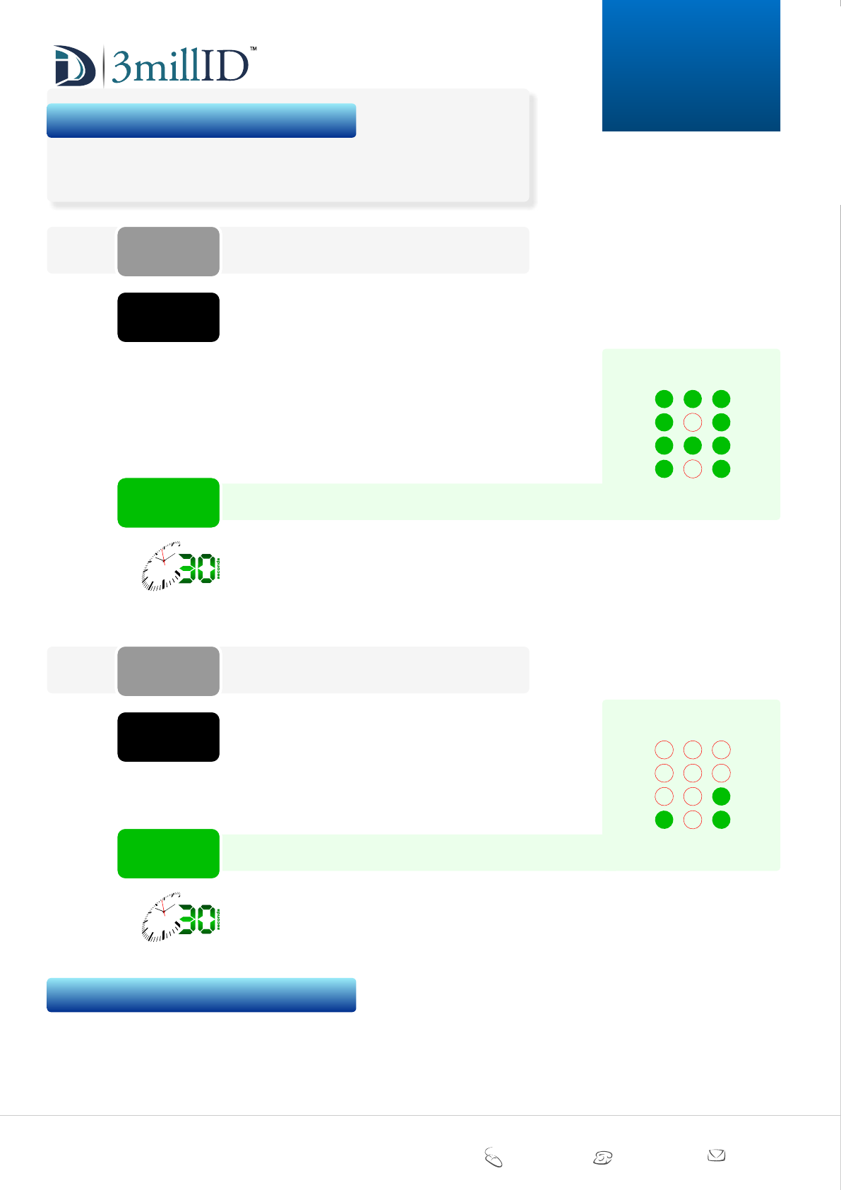
set PIN
PIN CODES
*98
set engineer’s PIN code
LOG OFF
PIN CODES
*99
EXIT CONFIGURATION MODE
example
*98oooonnnn#
oooo
nnnn
.....
.....
example
*99#
The following instructions give a step-by-step procedure for accessing the many features
supported by this reader.
4. keypad programming guide
Use this code to change the factory default PIN to your own
4 digit engineer’s PIN setting.
The factory default PIN = 1234
To set your new PIN to 6789 enter: *9812346789# once
the reader has been placed into programming mode.
After entering programming mode, the reader will time out
after approximately 30 seconds if no keys are pressed for
that duration. Any changes you may have made to values or
settings will be lost.
Remember to keep a record of your new PIN.
NOTE:
If you forget your PIN setting, you will need to contact your
INSTALLER or SUPPLIER to obtain a RESET code.
WARNING:
6
8
0
9
#
4
7
*
5
1 2 3
current PIN (4 digits) (factory default = 1234)
engineer’s PIN setting (4 digits)
Use this code to EXIT the CONFIGURATION MODE of the
reader.
Enter: *99# to exit CONFIGURATION MODE (and save any
settings made).
After entering programming mode, the reader will time out
after approximately 30 seconds if no keys are pressed for
that duration. Any changes you may have made to values or
settings will be lost.
You MUST use this code to ensure any changes to values
or settings you may have made, are safely SAVED to the
reader.
NOTE:
6
8
0
9
#
4
7
*
5
1 2 3