Thrane and Thrane A S 6282 Class A, AIS Transponder User Manual
Thrane & Thrane A/S Class A, AIS Transponder
UserManual.wiki
>
Thrane and Thrane A S
>
6282 User Manual
User manual
Navigation menu
Upload a User Manual
Namespaces
Wiki Guide
HTML
PDF
Info
Views
User Manual
Discussion / Help
Navigation
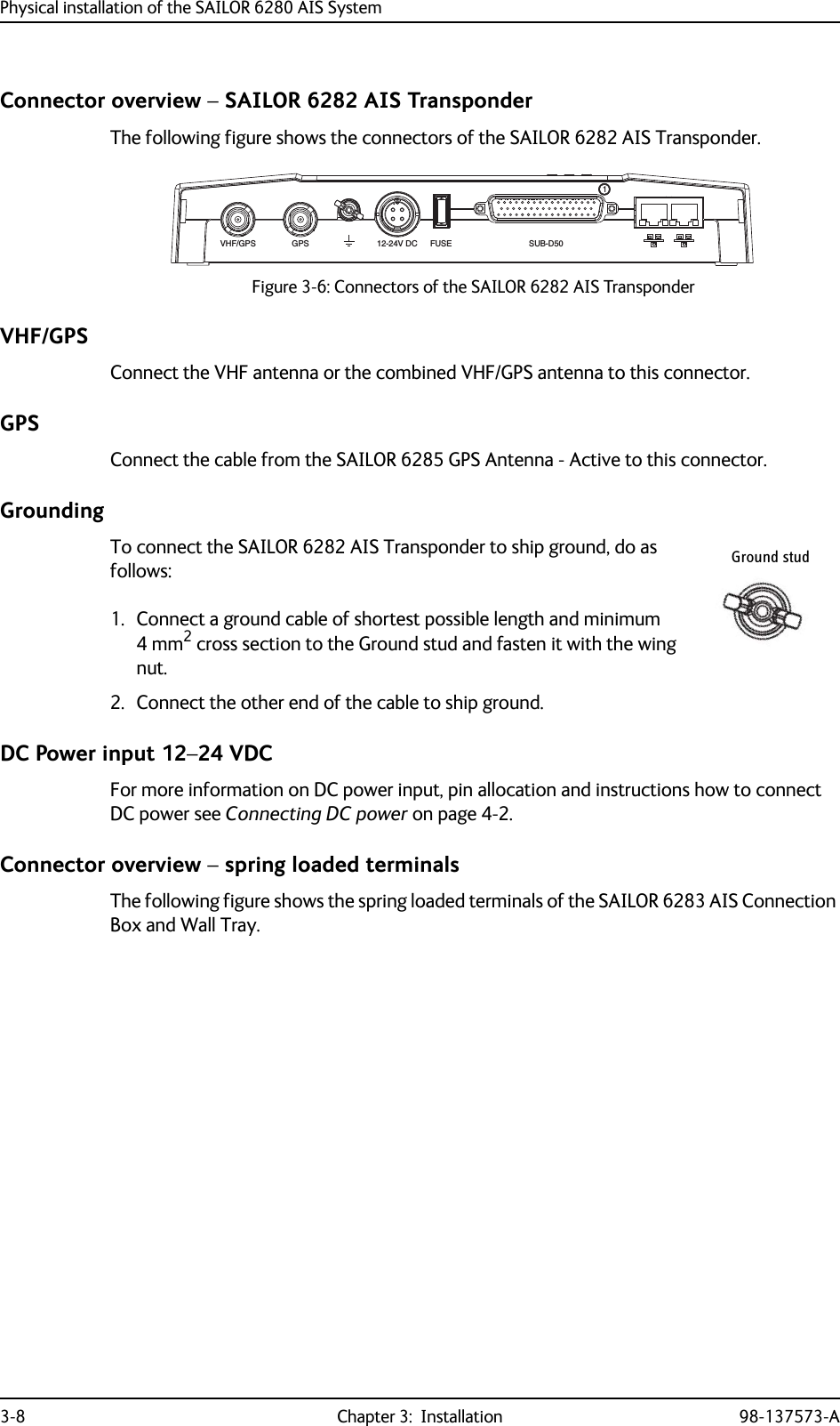
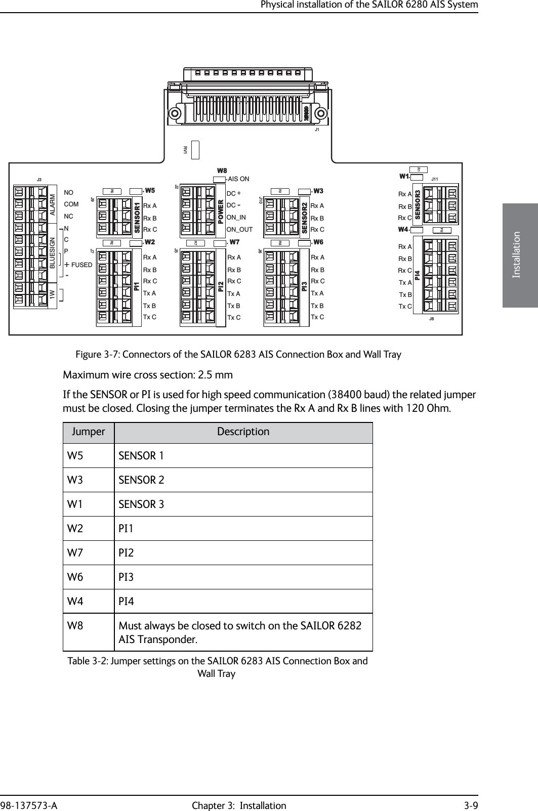
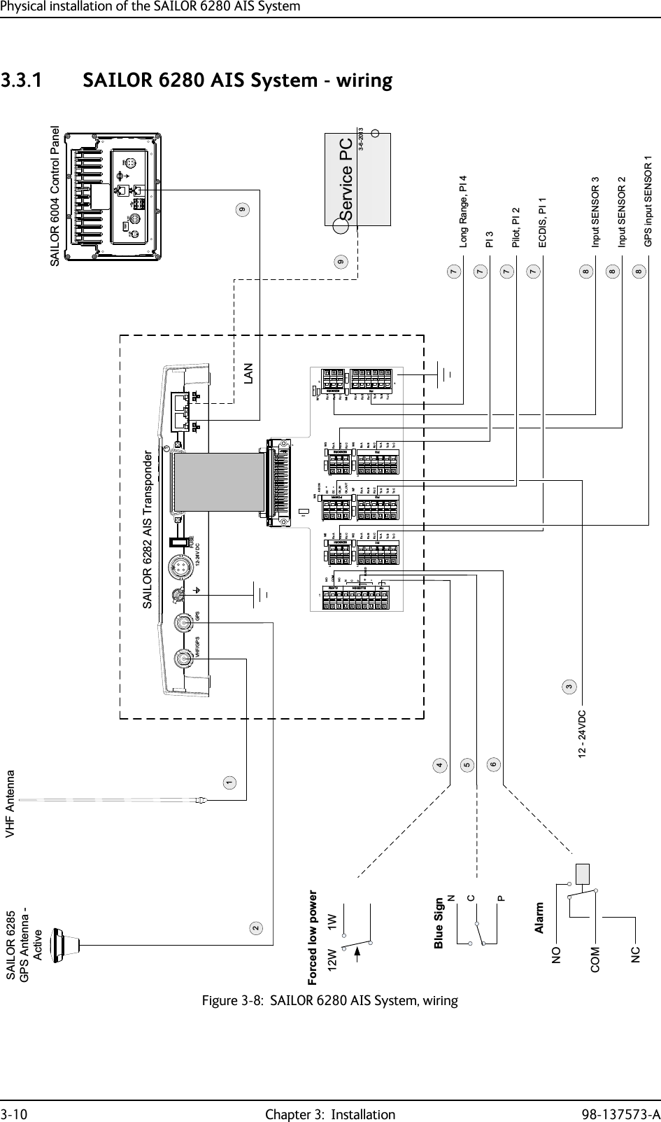
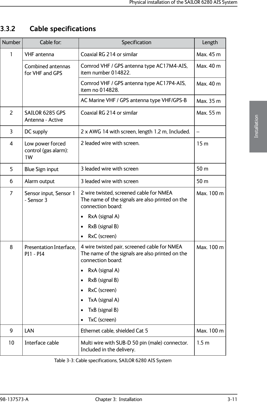
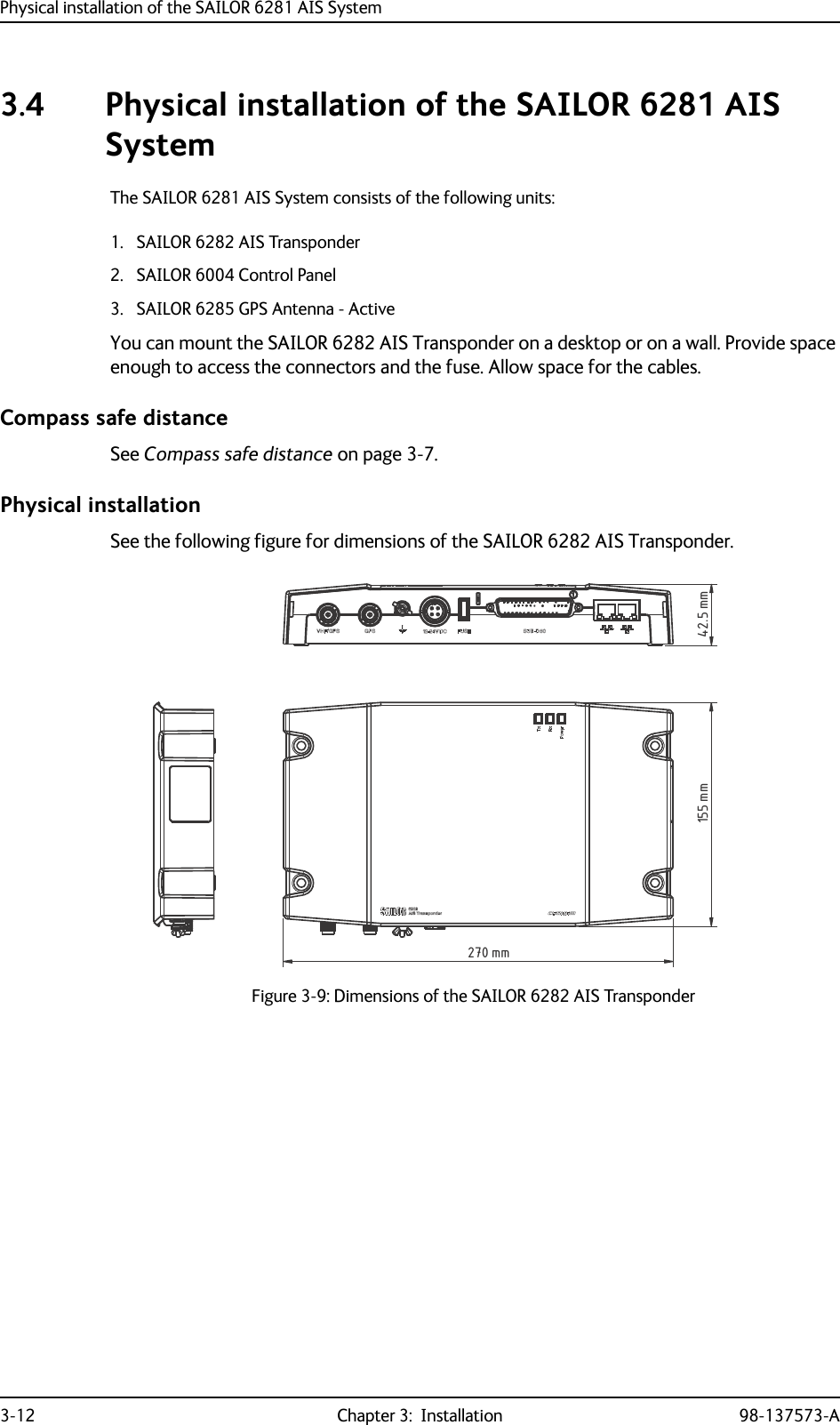
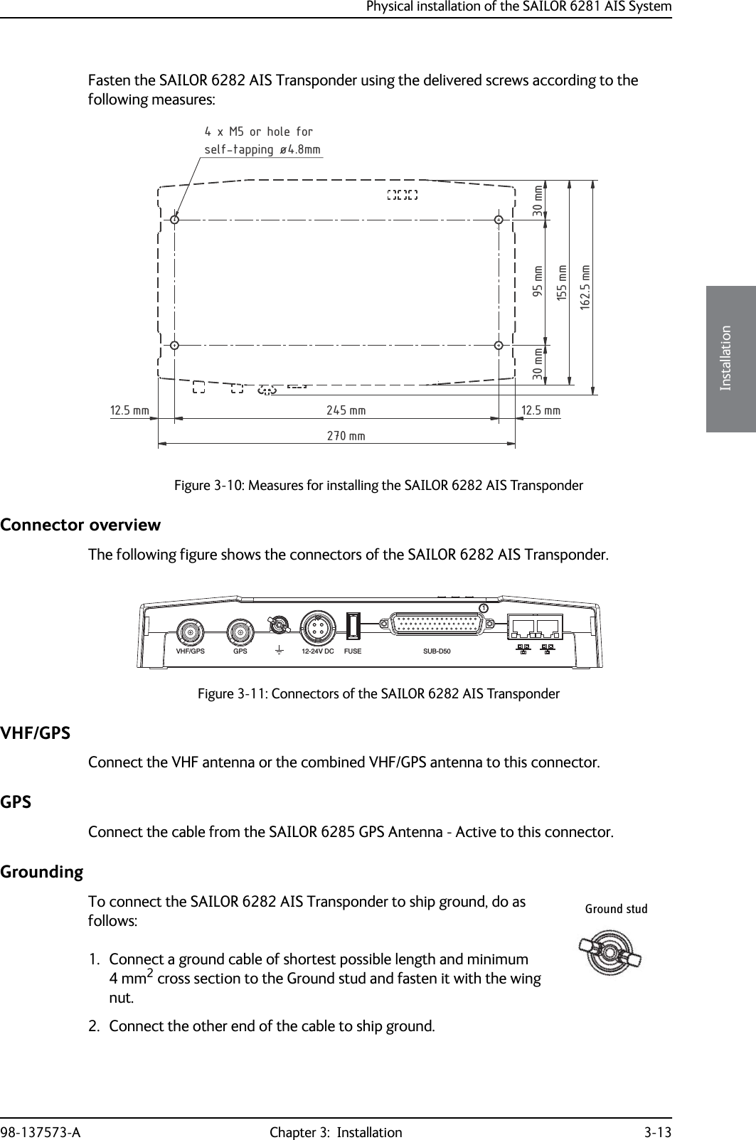
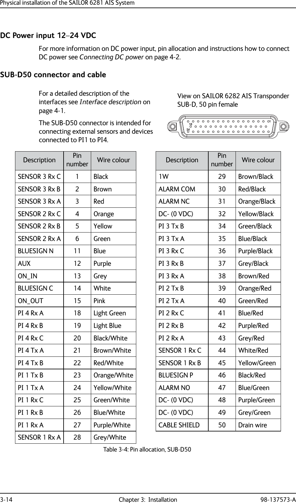
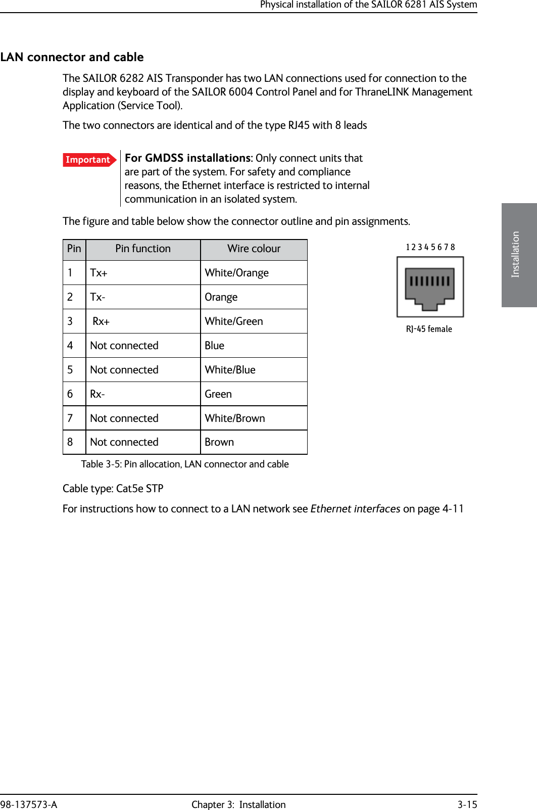
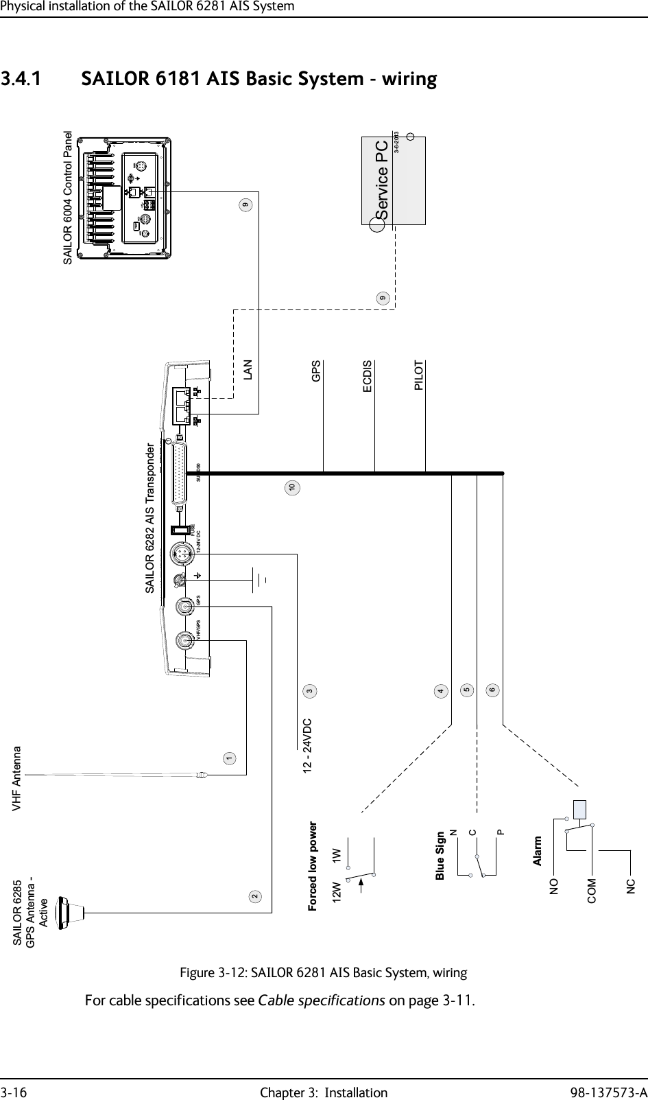
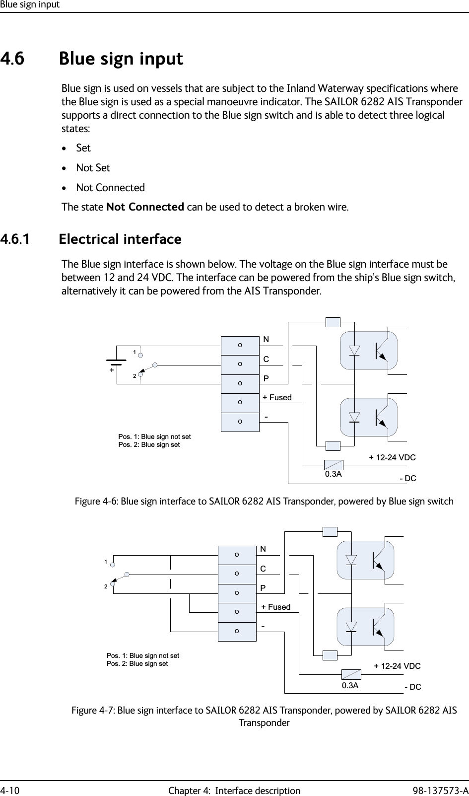
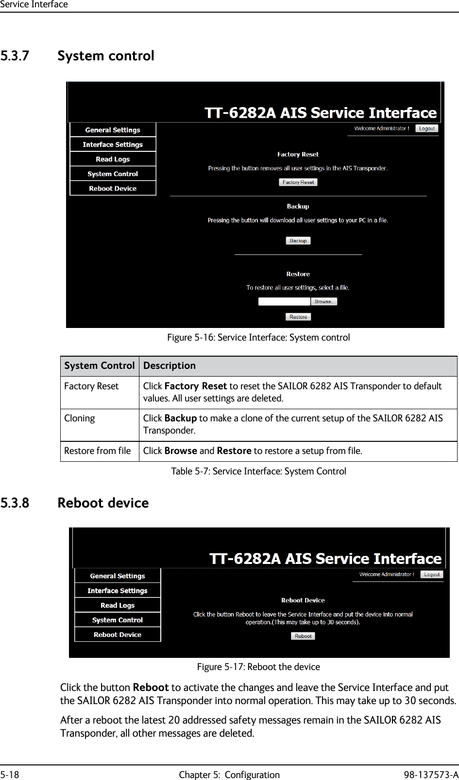
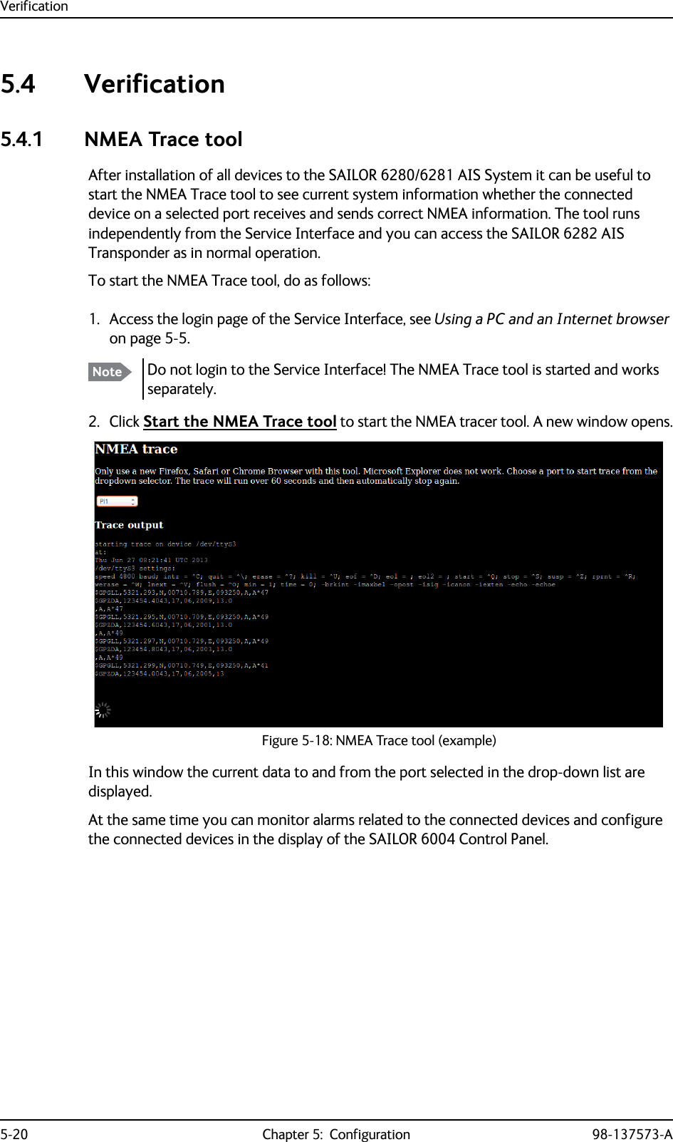
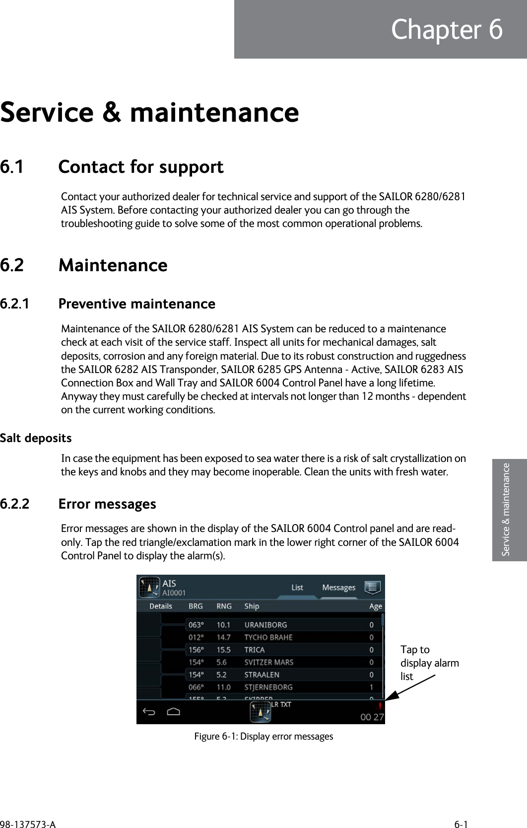
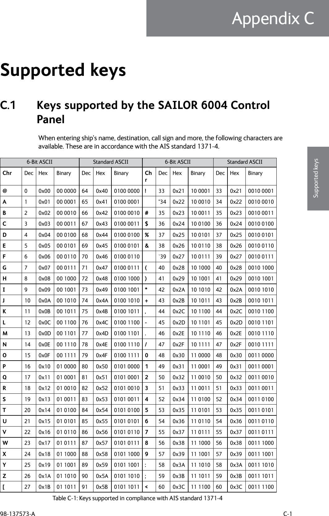
![Keys supported by the SAILOR 6004 Control PanelC-2 Appendix C: Supported keys 98-137573-A\28 0x1C 01 1100 92 0x5C 0101 1100 =61 0x3D 11 1101 61 0x3D 0011 1101]29 0x1D 01 1101 93 0x5D 0101 1101 >62 0x3E 11 1110 62 0x3E 0011 1110^30 0x1E 01 1110 94 0x5E 0101 1110 ?63 0x3F 11 1111 63 0x3F 0011 1111-31 0x1F 01 1111 95 0x5F 0101 1111Space 32 0x20 10 0000 32 0x20 0010 00006-Bit ASCII Standard ASCII 6-Bit ASCII Standard ASCIITable C-1: Keys supported in compliance with AIS standard 1371-4 (Continued)](https://usermanual.wiki/Thrane-and-Thrane-A-S/6282/User-Guide-2082849-Page-110.png)