Thrane and Thrane A S 6300 SAILOR 6311 MF/HF 150W DSC CLass A FCC User Manual SAILOR6301 UM
Thrane & Thrane A/S SAILOR 6311 MF/HF 150W DSC CLass A FCC SAILOR6301 UM
UserManual.wiki
>
Thrane and Thrane A S
>
6300 User Manual
>
manual system
Contents
1.
manual system
2.
manual system corrigendum
3.
Short emergency guide
4.
manual radio telex
5.
manual alarm panel
manual system
Navigation menu
Upload a User Manual
Namespaces
Wiki Guide
HTML
PDF
Info
Views
User Manual
Discussion / Help
Navigation


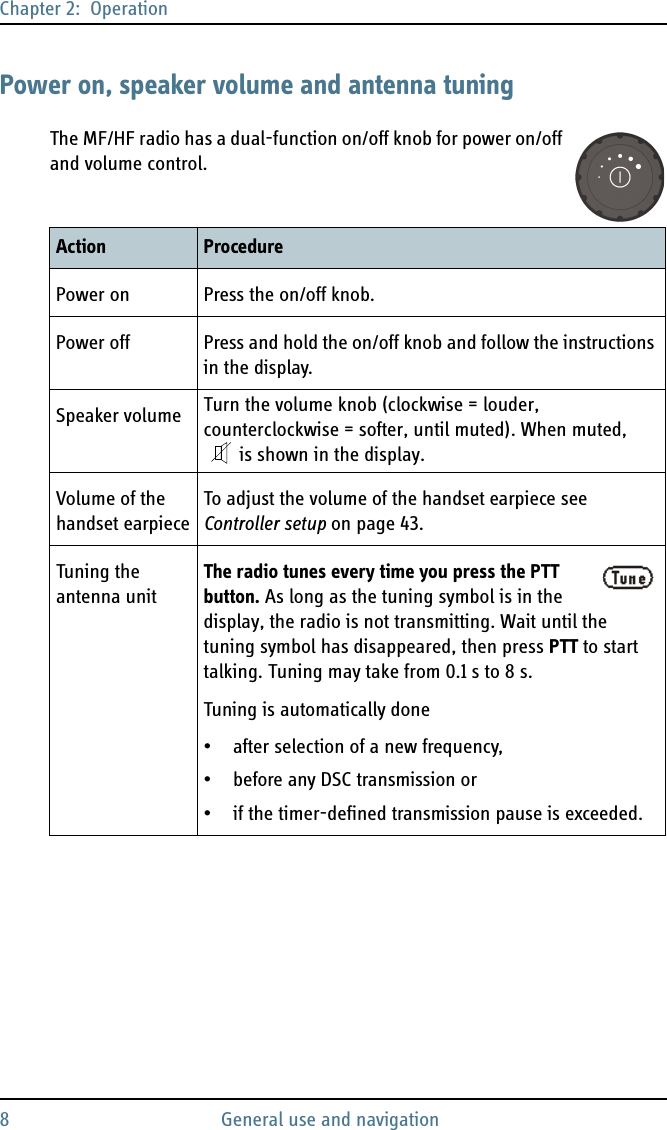
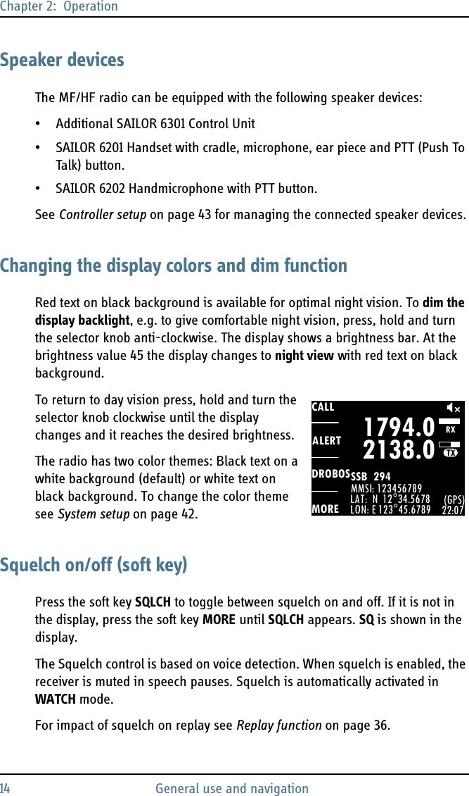
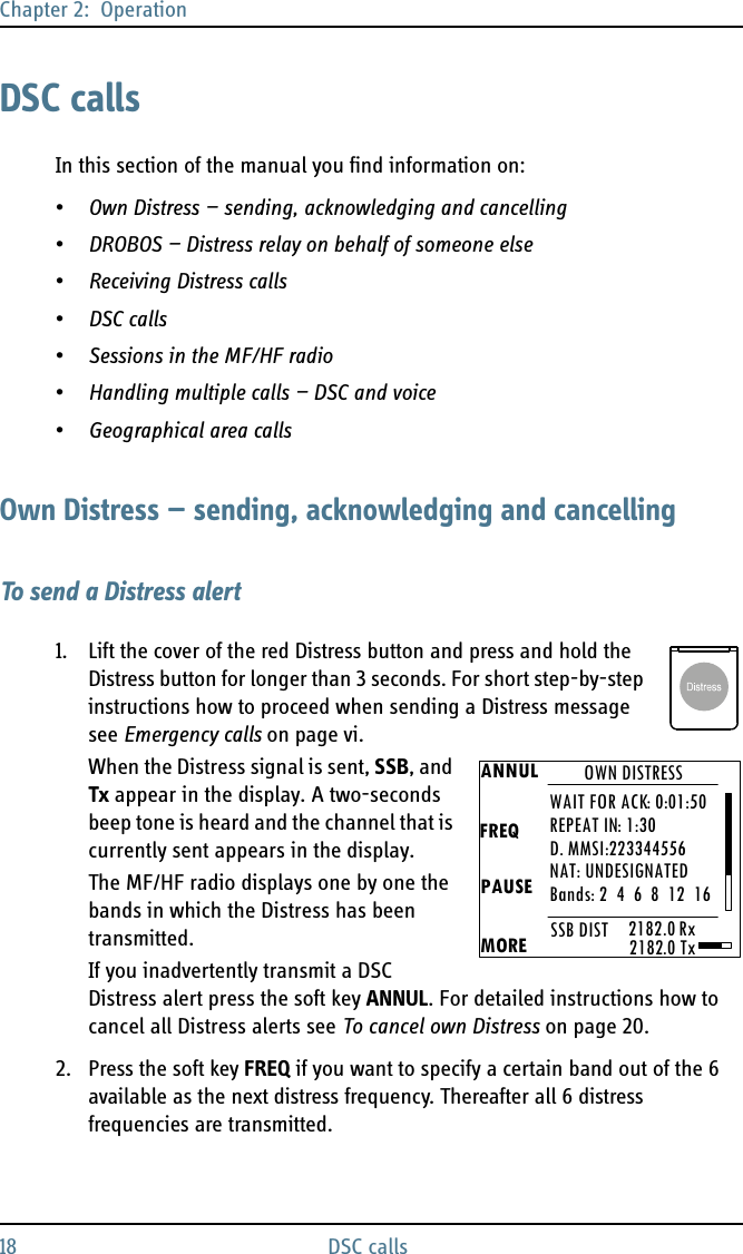
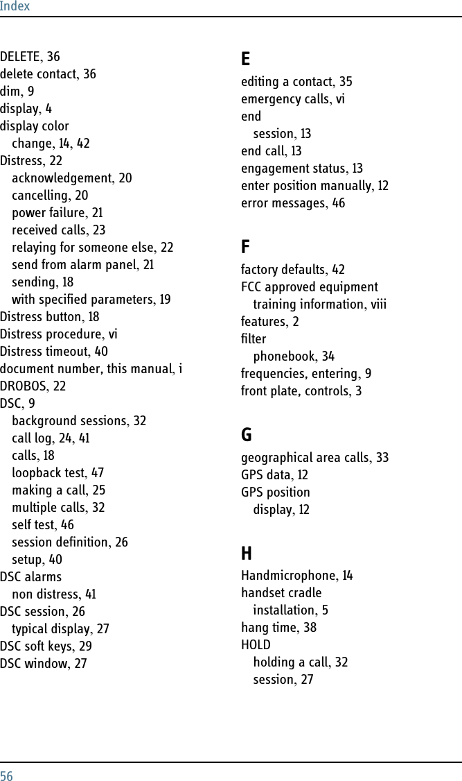
![Chapter 2: Operation16 Basic MF/HF radio communication4. When the TX indicator lights up and the transmission power bar shows activity, the transmission is active. Always say “Over.” before releasing the PTT button.5. To receive a radio signal, release the PTT button. When receiving a signal, the bar for received signal strength shows activity.Receiving a radio telephone callWhen you hear your ship’s name or call sign in the loudspeaker, the symbol RX shows that the radio is receiving on the frequencies displayed and the bar for received signal strength shows activity. Proceed as follows:1. Lift the Handset or take another speaker device.2. Press the PTT button and wait until the tune icon has disappeared. The symbol TX shows that the radio is transmitting on the frequencies displayed and the transmission power bar shows activity.3. Repeat the name of the station calling you and say: “This is [your ship’s name]”.4. Suggest a frequency pair by saying: “Frequencies [suggested frequencies]” and “Over.” and release the PTT button to allow the caller to confirm the suggested new frequencies.5. Switch to the new frequencies using the RX/TX button and the keypad and begin your conversation. Press PTT only when you are talking.NoteThe radio tunes every time you press the PTT button. As long as the tuning symbol is in the display, the radio is not transmitting. Wait until the tuning symbol has disappeared, then press PTT to start talking. Tuning may take from 0.1 s to 8 s.CALLALERTDROBOSMOREMMSI: 123456789N 12°34.5678E 123°45.6789 22:07GPS4357.04065.0SSB 401SQkHz/TXkHz/RX](https://usermanual.wiki/Thrane-and-Thrane-A-S/6300.manual-system/User-Guide-1463868-Page-30.png)
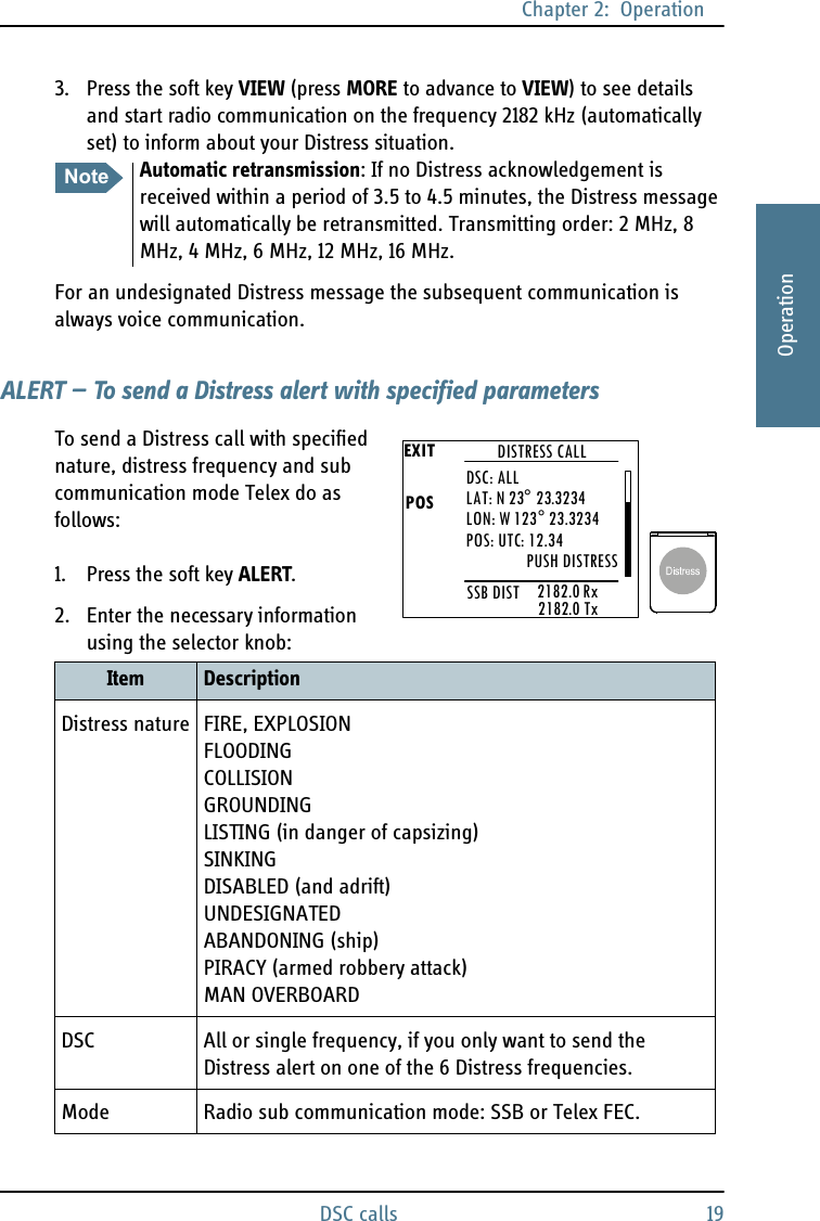
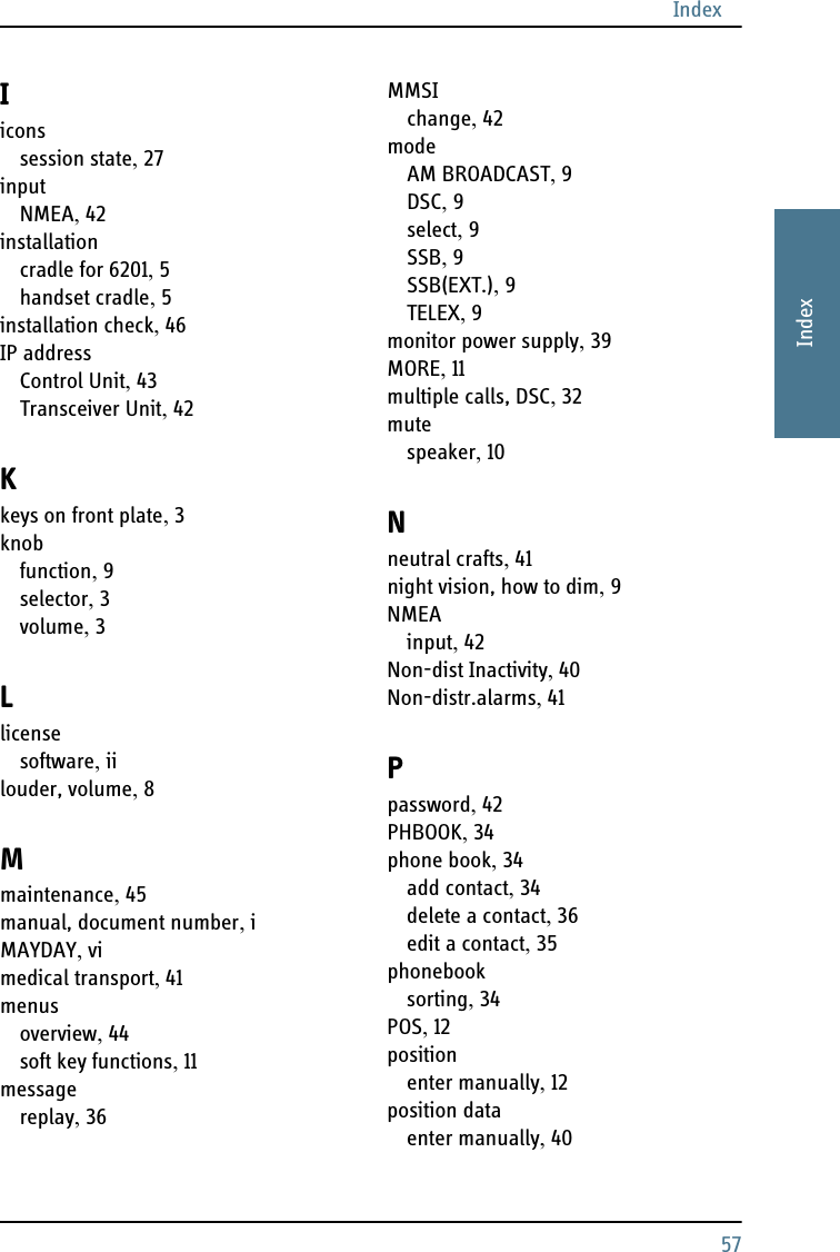
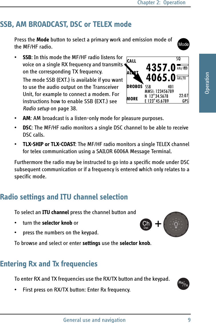
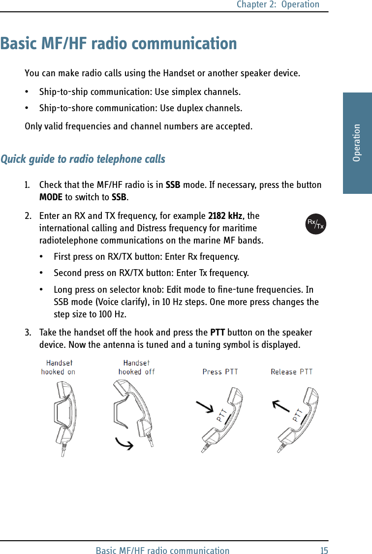
![Chapter 2: OperationWatch function 172222OperationMaking a radio telephone call1. Enter RX and TX frequencies or select an ITU channel.2. Lift the Handset or take a speaker device and press the PTT button, then wait until the tune icon has disappeared. The symbol TX shows that the radio is transmitting on the frequencies displayed. The transmission power bar shows activity,3. Say the name of the station you are calling three times.4. Say: “This is [your ship’s name]” and “Over.” and release the PTT button to listen. The symbol RX shows that the radio is receiving on the working channel displayed.5. When answered, agree upon a pair of frequencies, enter the new frequencies or ITU channel and start talking.Watch functionThe MF/HF radio radio has a dual watch function. The currently selected RX and TX frequencies and the Distress frequency 2182 kHz are watched.To start WATCH press the soft key WATCH. The display shows SSB-DUAL, the tab for an active voice session and SQ. To stop WATCH press the soft key WATCH or PTT on the speaking device.CALLALERTDROBOSMOREMMSI: 123456789N 12°34.5678E 123°45.6789 22:07GPS4357.04065.0SSB 401SQkHz/TXRXkHz/NoteIf a popup window with the information TX inhibit is displayed when you want to make a radio call, your MF/HF radio is temporarily blocked for sending. Consult your radio responsible for information when you can start transmitting.](https://usermanual.wiki/Thrane-and-Thrane-A-S/6300.manual-system/User-Guide-1463868-Page-31.png)