Thrane and Thrane A S 6390 NAVTEX Receiver User Manual
Thrane & Thrane A/S NAVTEX Receiver
UserManual.wiki
>
Thrane and Thrane A S
>
6390 User Manual
>
Installation manual
Contents
1.
User manual
2.
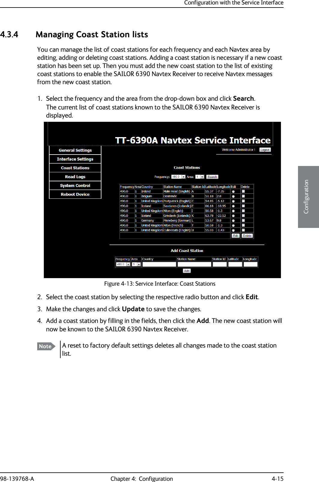
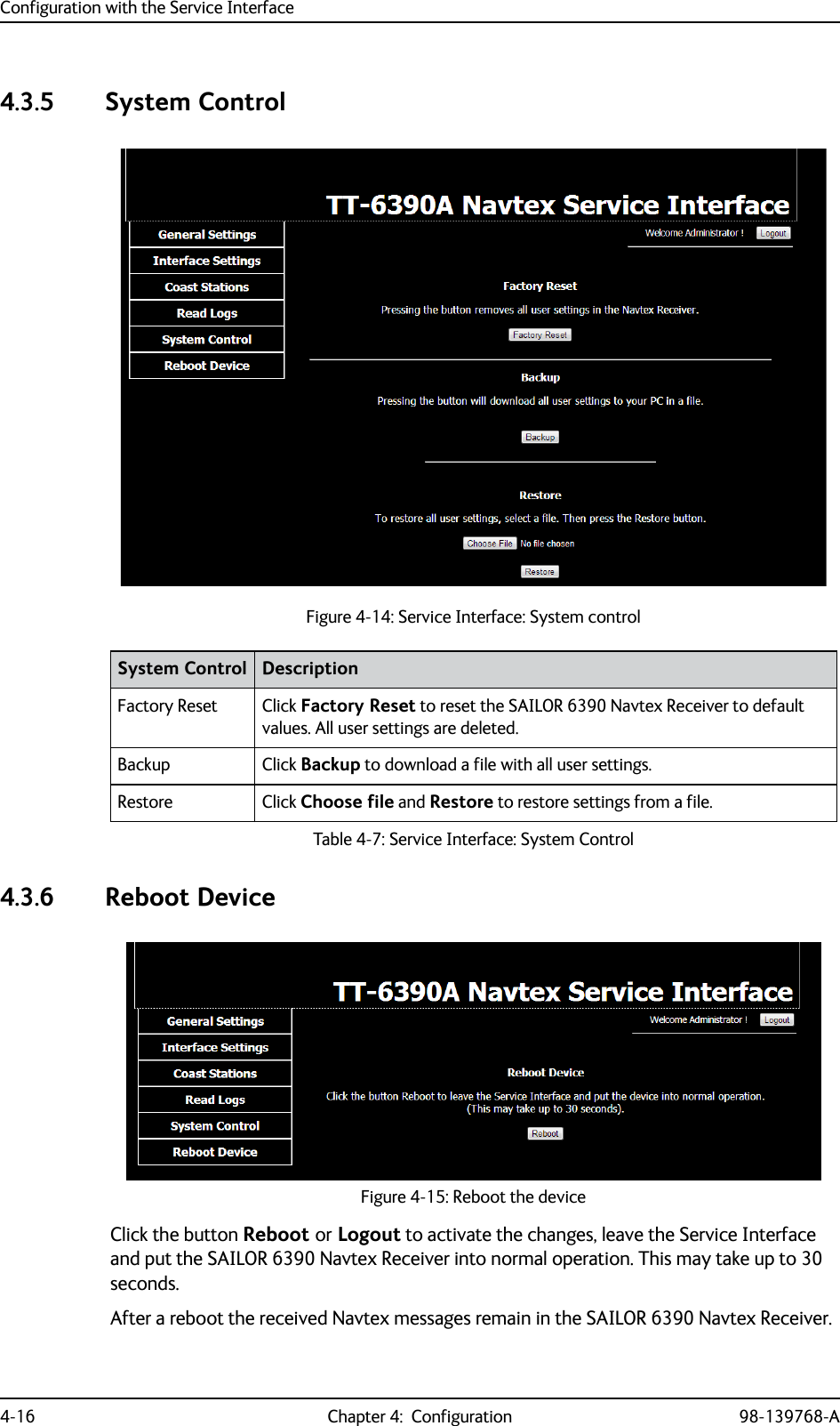
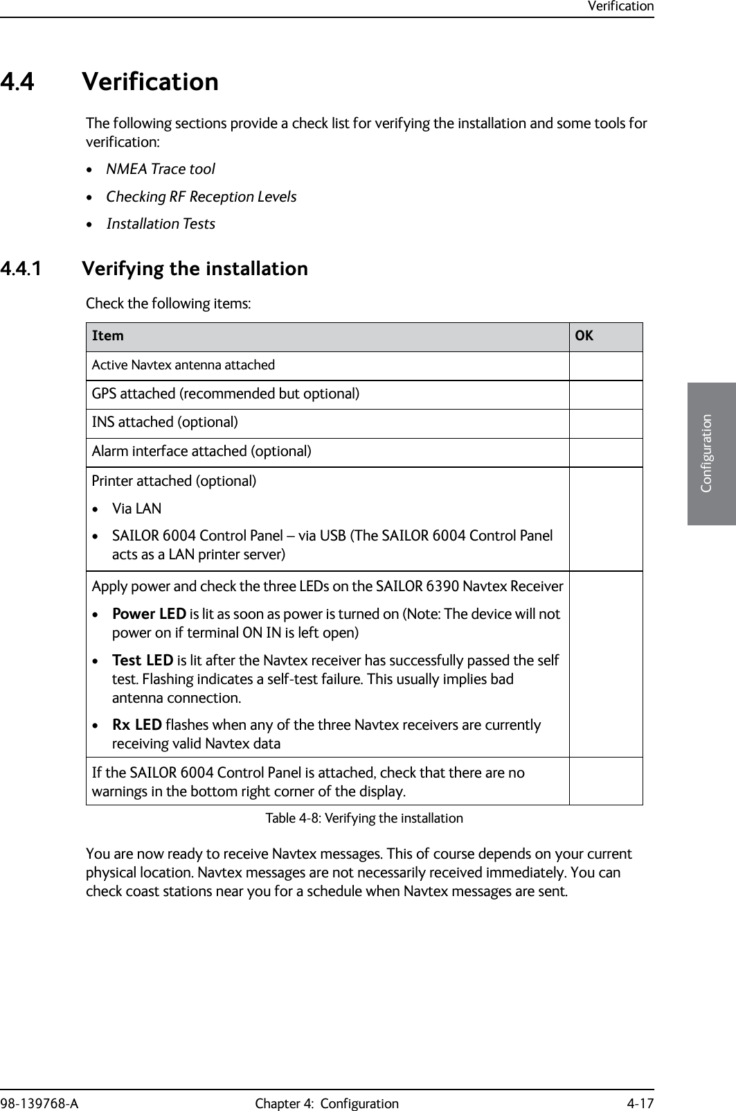
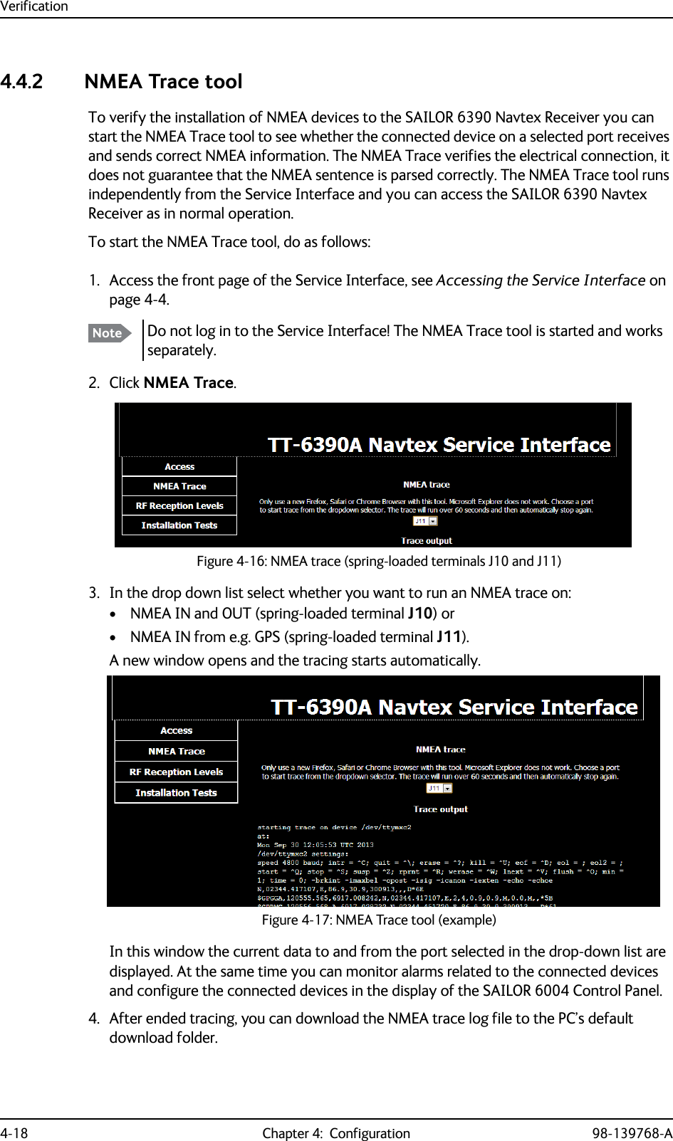
Installation manual
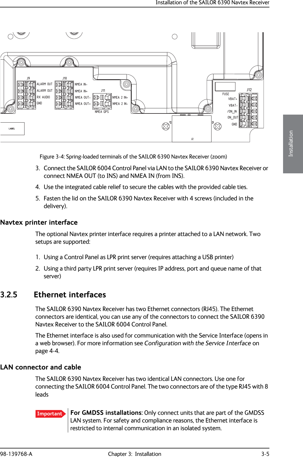
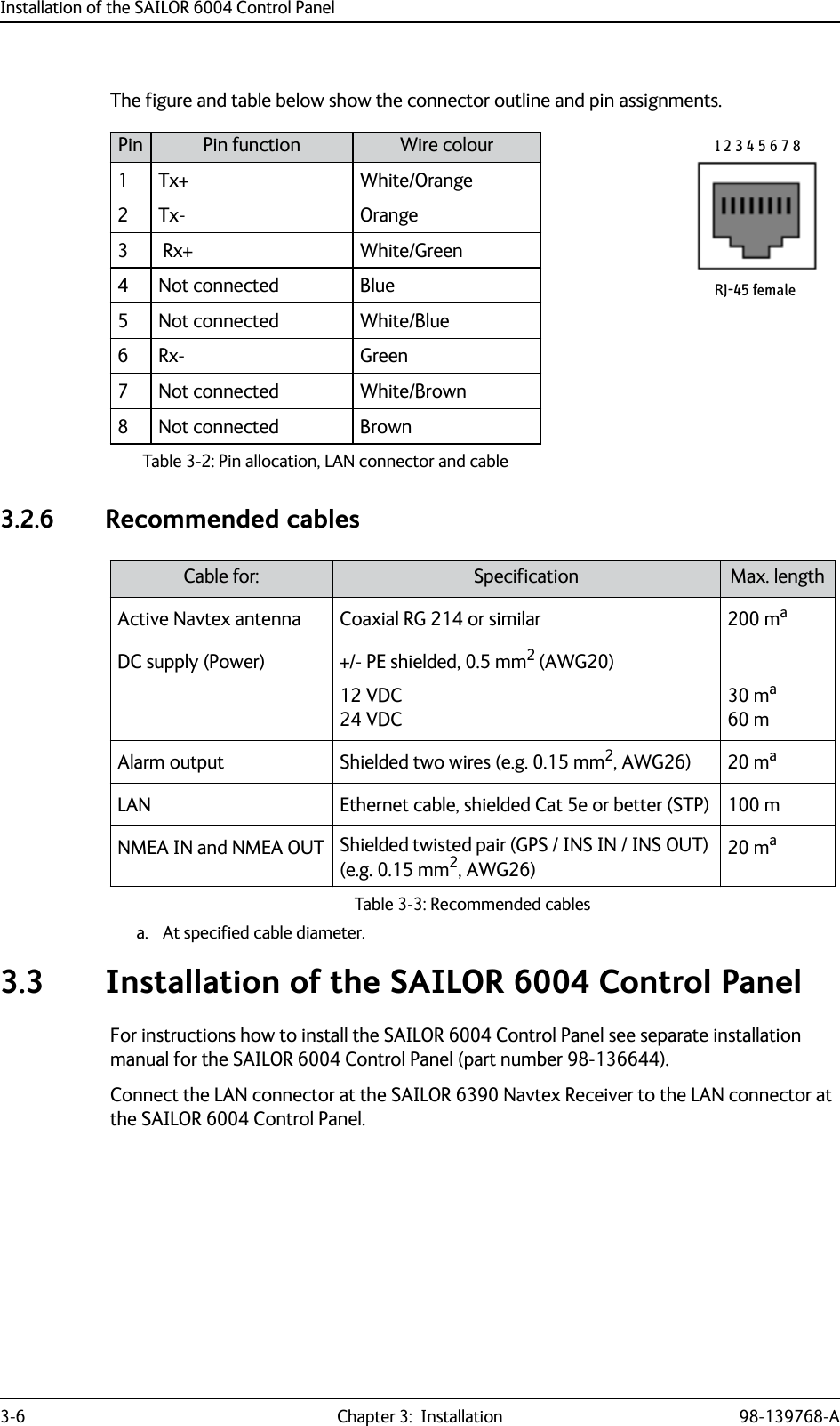
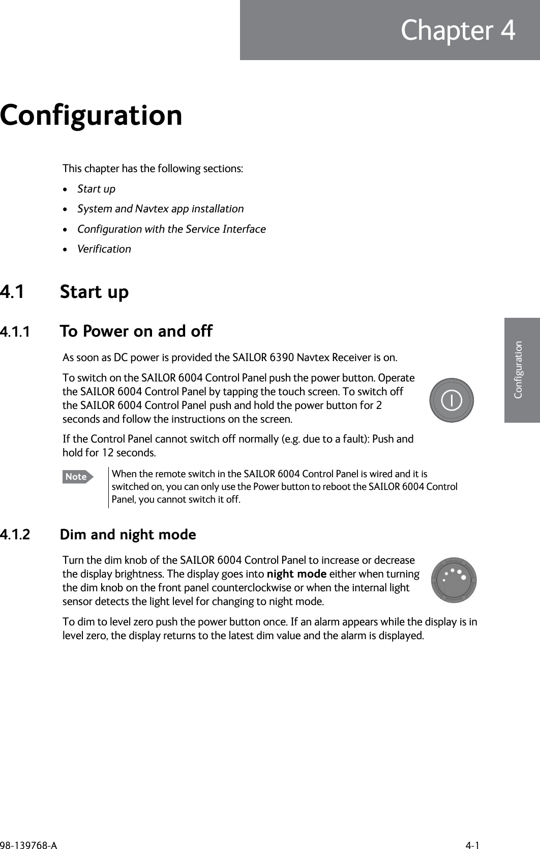
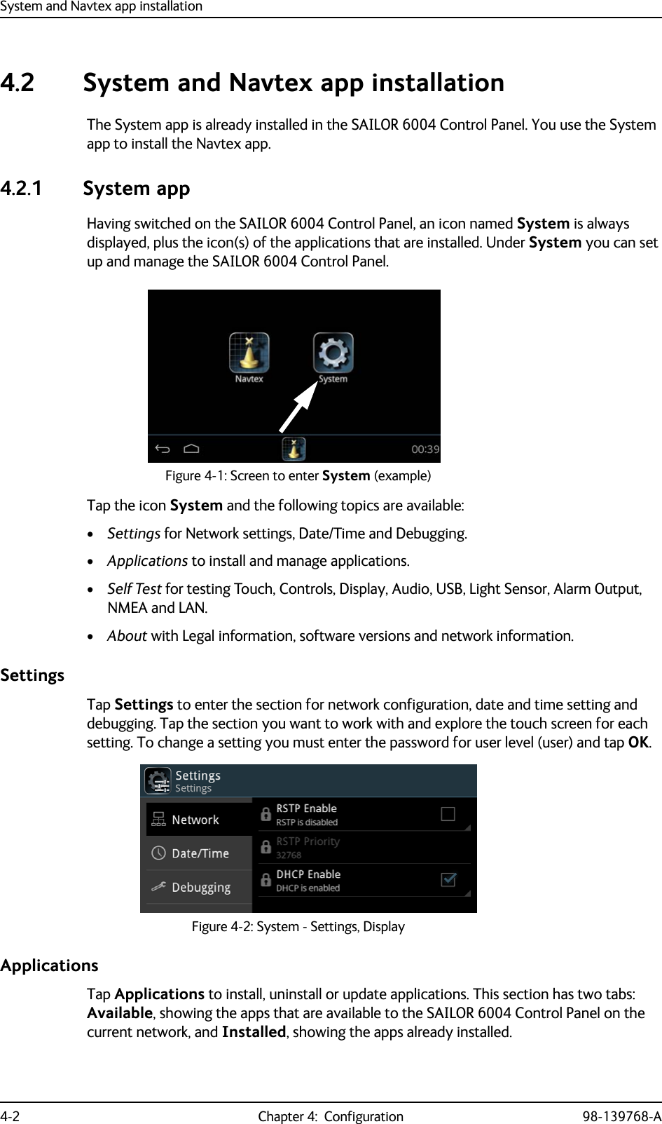
Installation manual
Navigation menu
Upload a User Manual
Namespaces
Wiki Guide
HTML
PDF
Info
Views
User Manual
Discussion / Help
Navigation