Thrane and Thrane A S AERO-HSD Aeronautical Satellite Telephone User Manual AeroHSD 98 119959 a18
Thrane & Thrane A/S Aeronautical Satellite Telephone AeroHSD 98 119959 a18
Users Manual
Thrane & Thrane A/S
Aero-HSD+
User Manual
Copyright Thrane & Thrane A/S
ALL RIGHTS RESERVED
Information in this document is subject to change
without notice and does not represent a commitment on
the part of Thrane & Thrane A/S.
© 2003 Thrane & Thrane A/S. All rights reserved. Printed
in Denmark.
Trademark Acknowledgements:
WinPoET is a trademark of iVasion, a RouterWare
Company.
Company addresses:
• Denmark:
Thrane & Thrane A/S,
Lundtoftegårdsvej 93 D,
DK-2800 Lyngby,
Denmark
Tel: +45 39 55 88 00
• USA:
LandSea Systems, Inc.
509 Viking Drive, Suites K, L and M
Virginia Beach, VA 23452
USA
Tel: +1 757 463-9557
Document no. TT98-119959-A.
Release date: 12 December 2003

Table of Contents
Dec 2003 3
Table of Contents
1. About the Manual ..................................................... 7
1.1. Overview .......................................................... 7
1.2. Audience .......................................................... 8
1.3. Software Version................................................ 8
1.4. Related Documentation........................................ 9
2. Introduction........................................................... 11
2.1. The Inmarsat Aero Service................................. 11
2.1.1. Overview............................................... 11
2.1.2. Service Explanation ................................. 14
2.2. The Aero-HSD+ System ..................................... 16
2.2.1. Features ............................................... 16
2.2.2. System Components................................ 17
2.3. The Full Feature Handset ................................... 21
2.3.1. Display and LEDs ..................................... 22
2.3.2. Function Buttons .................................... 25
2.3.3. Alpha-Numeric Buttons............................. 29
2.4. The Auxiliary Handset ........................................ 31
2.4.1. LEDs ..................................................... 32
2.4.2. Function Buttons .................................... 32
2.4.3. Numeric Buttons ..................................... 34
2.5. Other Handset Types ........................................ 36
2.5.1. Sigma 7 or 2.4 GHz Cordless phone .............. 36
3. Getting started....................................................... 37
3.1. Initialising the System....................................... 37
3.1.1. To Power on the System.......................... 37
3.1.2. To Power off the System.......................... 38
3.2. Pin Codes........................................................ 39
4. Operation .............................................................. 41
4.1. Menu Navigation............................................... 41
4.2. Using the Full Feature Handset............................ 43
4.2.1. Making a H+ Call from the Handset ............. 43

Table of Contents
4 Dec 2003
4.2.2. Making a Call Using the Phone Book.............44
4.2.3. Using the Quick Dial Function .....................44
4.2.4. Redialling a Number ..................................44
4.2.5. Making Internal Calls.................................45
4.2.6. Transferring a Call....................................46
4.2.7. Making a Conference Call...........................47
4.3. Using the Auxiliary Handset .................................48
4.3.1. Making a Call...........................................48
4.3.2. Storing a Phone Number............................49
4.3.3. Recalling a Phone Number from Memory ........51
4.3.4. Transferring a Call....................................52
4.3.5. Redialling a Number ..................................52
4.3.6. Muting the Microphone..............................52
4.4. Using the Sigma 7 Handset....................................53
4.4.1. Making a Call...........................................53
4.5. Using the 2.4 GHz Cordless Handset ......................54
4.5.1. Making a Call...........................................54
4.6. Other Call Functions ..........................................55
4.6.1. Making a Call from an ISDN Phone ...............55
4.6.2. Sending a Fax Using H+.............................55
4.6.3. Sending a Fax Using HSD...........................56
4.6.4. Calling the Terminal..................................57
4.7. The Menus.......................................................58
4.7.1. Phone Book.............................................58
4.7.2. HandsetSetup .........................................60
4.7.3. Ring Profile .............................................65
4.7.4. Lock System...........................................65
4.7.5. Logon Menu ............................................66
4.7.6. System Setup .........................................73
4.7.7. Status ...................................................84
5. PC Connection ........................................................89
5.1. ISDN and MPDS Overview ...................................89
5.2. Setup of Data Equipment ....................................90
5.2.1. Hardware connection................................90
5.2.2. Setting up MPDS via Ethernet and PPPoE......92
5.2.3. Setting up ISDN.......................................96
5.2.4. Setting up a Router................................ 100

Table of Contents
Dec 2003 5
5.2.5. Setting up a H+ Modem Connection ...........100
5.3. Connecting to the Network................................102
6. Troubleshooting.....................................................103
6.1. Overview .......................................................103
6.2. Error codes ....................................................104
6.2.1. BITE Errors ...........................................104
6.2.2. Cause Codes .........................................105
6.3. List of Cause Codes .........................................106
6.3.1. Logon Cause Codes ................................106
6.3.2. Cause Codes after Logon.........................108
Appendix A - Menu Tree.................................................111
Glossary......................................................................113
Index .........................................................................119

Table of Contents
6 Dec 2003
This page is intentionally left blank

About the Manual
Dec 2003 7
1
1. About the Manual
1.1. Overview
Congratulations on purchasing your Aero-HSD+ product.
The Aero-HSD+ system makes it possible for you to
communicate from virtually any ocean region in the world
using the Inmarsat Swift64 and H+ service established
by Inmarsat.
This manual has the following chapters:
Chapter 2 Introduction - an overview of the Inmarsat
Aero system and its services. Also a brief description of
the Aero-HSD+ system.
Chapter 3 Getting started - a description of how to start
up the system and the use of pin codes.
Chapter 4 Operation - a detailed description of the menu
system in the terminal, and a description of the call
functions.
Chapter 5 PC – a description of how to set up a
computer for use with the Aero-HSD+ system.
Chapter 6 Troubleshooting – a short troubleshooting
guide and a description of the error messages that may
appear in the handset. Also a list of Cause codes, and
information on where to get further help if necessary.
Appendix A - Menu Tree

About the Manual
8 Dec 2003
1
1.2. Audience
This manual is a user manual for the Aero-HSD+ System.
The audience of the manual includes aircraft personnel
and users of the system.
1.3. Software Version
This manual was written for the Aero-HSD+ System with
the following software:
Aero-HSD+ Application Code version 1.01.

About the Manual
Dec 2003 9
1
1.4. Related Documentation
Apart from the User Manual, the following related
documentation applies to the Aero-HSD+ system:
Title Document
Number
Aero-HSD+ Quick Guide
Contains short instructions for the daily
use of the Aero-HSD+ system.
TT-99-119960
Aero-HSD+ Installation and
Maintenance Manual
Contains extensive information for the
personnel who install the system in the
aircraft.
TT-98-113625
Sigma7 Telephone Handset Manual
(by International Communications
Group)
PN# 500114
2.4 GHz Cordless, Installation Manual
(by International Communications
Group)
PN# 500484
“AeroROUTER 700”
(by International Communications
Group)
PN# 500420

About the Manual
10 Dec 2003
1
This page is intentionally left blank

The Inmarsat Aero Service Introduction
Dec 2003 11
2
2. Introduction
2.1. The Inmarsat Aero Service
2.1.1. Overview
The Inmarsat Swift64 (also called High Speed Data or
HSD) and H+ services are based on 4 Geo-stationary 3rd
generation satellites situated above the equator. Geo-
stationary means that the satellites are always located
in the same position, i.e. they rotate at the same speed
as that of the earth. Each satellite covers a certain area
(footprint) and supports a number of powerful spot-
beams making the service available in virtually all ocean
regions on the earth between approximately 70°N and
70°S.
Note: the ISDN and MPDS services are only available on
Aero-HSD+ systems when the aircraft is positioned inside
an area with Spot Beam coverage.
The 4 Geo-Stationary Inmarsat Satellites
The satellites are your connection to the worldwide
networks, and they are managed by the Network Co-
ordination Stations (NCSs), run by Inmarsat. The primary

Introduction The Inmarsat Aero Service
12 Dec 2003
2
functions of the NCSs are to constantly keep track of
which terminals are logged on to the system, and assign
a free channel when a call is made.
The gateway between the public network and the
satellites is operated by Land Earth Stations (LES) for
the high speed data communication or Ground Earth
Stations (GES) for the global voice, fax and PC modem
data capabilities. The LES and GES are run by different
operators around the world.
The services supported by the Inmarsat Fleet comprise:
• High speed services (64 kbit/s)
• 64 kbit/s universal data
• 56 kbit/s data
• Speech
• 3.1 kHz audio
• MPDS (Mobile Packet Data Service)
• Low speed services (2.4 kbit/s)
• Voice
• Fax
• Data
• Packet Data Channel
For a more detailed explanation of the services, please
refer to the section Service Explanation on page 14.
The Inmarsat Aero Service Introduction
Dec 2003 13
2
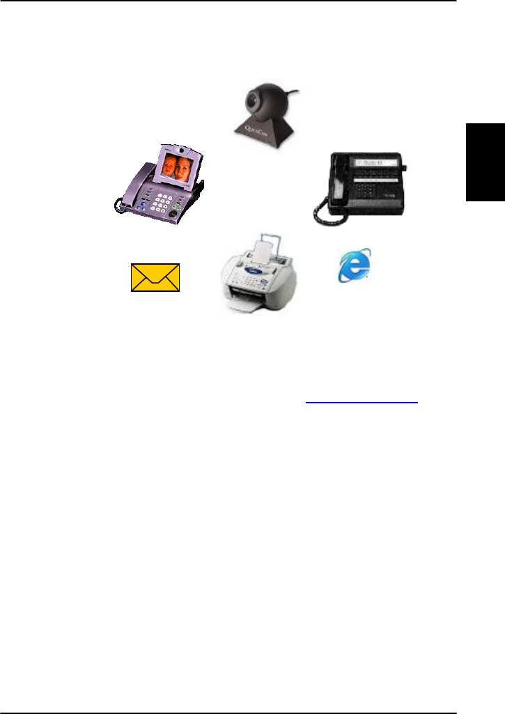
The above mentioned services allow for a wide range of
applications. Examples are shown below.
Important notice: Before a terminal can be used on the
network, it has to be commissioned by one of the
Inmarsat Service Providers (ISPs). For further information
on commissioning, refer to our site www.tt.dk/aero/isp
Video
Phone
STE/STU
phone
Webcam
E-mail
FAX
WWW

Introduction The Inmarsat Aero Service
14 Dec 2003
2
2.1.2. Service Explanation
The H+ services have a lower tariff than the high speed
services, which are high quality audio or high speed data
services and thus require more bandwidth.
High Speed Services
The 64 kbit/s UDI (Unrestricted Digital Information)
service enables the bi-directional transmission of data to
and from terrestrial 64 kbit/s ISDN and MPDS networks.
The 56 kbit/s DATA service is similarly used to make a
connection to 56 kbit/s ISDN networks, which are
primarily used in North America.
The Speech and 3.1 kHz audio services make it possible
to establish high quality analogue connections with
quality equal to terrestrial analogue connections via
digital networks/switches. The Speech service is used for
high quality voice connections, whereas 3.1 kHz audio
can be used to transfer analogue signals between fax
machines and modems with an analogue 2-wire
interface. The 3.1 kHz audio service is transparent, and is
suitable for all analogue applications including secure
telephones.
The MPDS service is a packet data service where the
tariff depends on the amount of data transmitted. This
service is a more cost-effective solution for web
browsing, and other applications where there is no need
for constant transmission of data in both directions. It is
also suitable for applications where a constant
connection is required, because the user is no longer
charged the “per minute rate”.

The Inmarsat Aero Service Introduction
Dec 2003 15
2
H+ Services
The H+ service supports near terrestrial-quality Voice at
4.8 kbit/s, over two different physical channels in both
global- and spot beam. This means that the user is able
to have 2 voice connections up at all times. This can be
two incoming, two outgoing or one incoming and one
outgoing connection. This service is less expensive than
an ISDN connection, with only a small cost in voice-
quality.
Besides using the two voice-channels for voice, one or
both of the channels can be used for a modem or fax
connection. In both circumstances, the maximum bit rate
is 2.4kbit/s. The fax or modem can be connected to the
two-wire interface. If a fax or modem uses a channel,
this channel cannot be used for voice at the same time.
H+ also provides a low speed packet data mode, which
allows data transfers at up to 1.2 kbit/s. This service can
be used by an AFIS, ACARS or CMU to send data over the
satellite link.

Introduction The Aero-HSD+ System
16 Dec 2003
2
2.2. The Aero-HSD+ System
2.2.1. Features
The Aero-HSD+ System is a unique multi-channel solution,
combining the global voice, fax and PC modem data
capabilities of the Inmarsat Aero H+ service with the
Inmarsat Swift64 aeronautical High Speed Data service.
The Aero-HSD+ system provides the following features:
• One 64 kbit/s High Speed Data channel
• 2 global voice, fax and PC modem data channels
• 1 channel for cockpit data
• ISDN for large file transmissions, videophone etc.
• MPDS “pay by the bit” – well suited for Internet, e-
mails etc.
• RS-422/Ethernet for airborne server/IP router
• STE/STU for secure, encrypted transmissions
• ARINC 741 antenna compatibility
• Small, compact and light-weight system
• Easily upgraded to the next generation Inmarsat
high speed satellite platform (BGAN)

The Aero-HSD+ System Introduction
Dec 2003 17
2
2.2.2. System Components
The Aero-HSD+ System includes the following system
components:
• TT-5035A Satellite Data Unit (SDU)
• TT-5014A High Power Amplifier (HPA)
• TT-5035A-001 Configuration module (CM)
• TT-5620A Full Feature Handset
• TT-5622A Full Feature Cradle
• TT-5621B Auxiliary Handset
• TT-5622B Auxiliary Cradle
• Accessories (manual, software, etc.)
A minimum working system has at least a TT-5035A SDU,
TT-5035A-001 CM, TT-5014A HPA, one TT-5620A Full
Feature Handset, one TT-5622A Full Feature Cradle plus
a High Gain Antenna system.
A full system may comprise up to six handsets, two of
which are using the 2-wire POTS interfaces, which can
also be used for faxes, PC modems, headset interface
etc.
Instructions on how to assemble the system are found in
the Installation and Maintenance Manual, together with
specifications and information on wiring.
Introduction The Aero-HSD+ System
18 Dec 2003
2
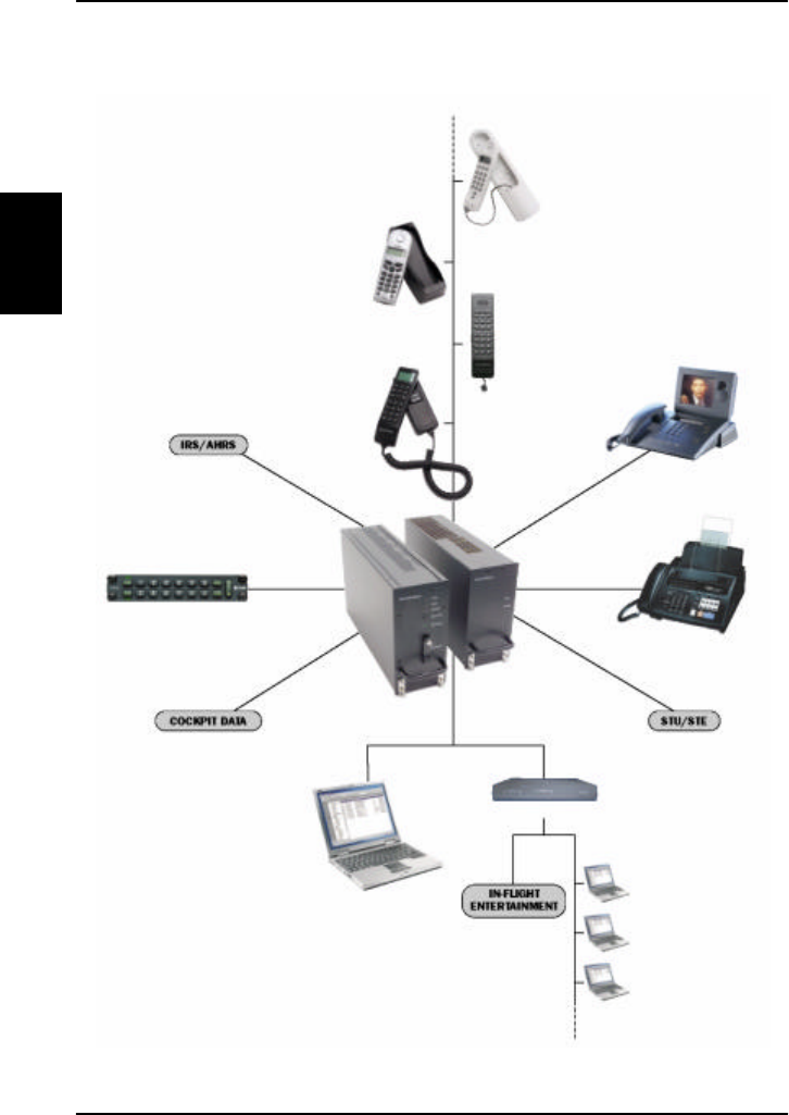
The Aero HSD+ system with various options
Flush-Mount
Wireless
Aux. Handset
Full Feature
Videophone
Headset Interface Box
Fax
High Speed Data
Router/Server
Laptop/PC
AFIS/ACARS, CMU
etc.
Secure Communication
PC #1
PC #2
PC #3
LAN/WLAN
The Aero-HSD+ System Introduction
Dec 2003 19
2
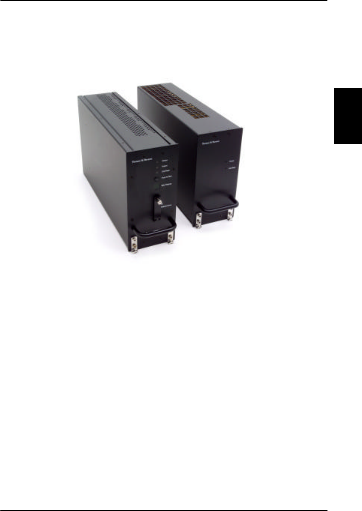
The TT-5035A Satellite Data Unit (SDU) and the TT-
5014A High Power Amplifier (HPA)
TT-5035A Satellite Data Unit (SDU)
The SDU is the controlling unit of the Aero-HSD+ system.
A Configuration Module (CM) and all the interfaces,
except for the maintenance port, are located on the rear
of the TT-5035A Satellite Data Unit (SDU).
TT-5014A High Power Amplifier (HPA)
The High Power Amplifier (HPA) is a Linear High Power
Amplifier capable of amplifying the transmission signals of
all 4 Aero-HSD+ channels simultaneously.
SDU HPA
Introduction The Aero-HSD+ System
20 Dec 2003
2
TT-5620A Full Feature Handset and TT-5622A Full
Feature Cradle
The Full Feature
Handset is used to
configure the system
and to make and
receive calls. See
section 2.3 for a
description of
buttons, LED's and
display of the
handset.
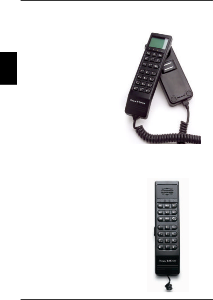
TT-5621B Auxiliary Handset and TT-5622B Auxiliary
Cradle
The Auxiliary Handset is used to
receive and to make calls.

The Full Feature Handset Introduction
Dec 2003 21
2
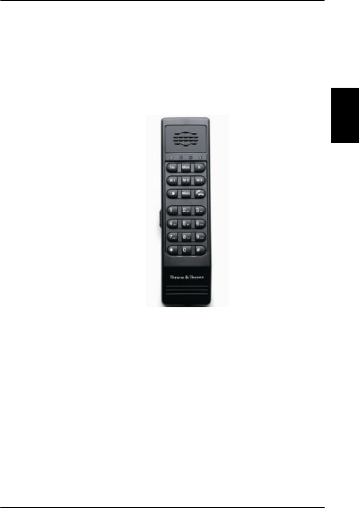
2.3. The Full Feature Handset
The Full Feature Handset is the primary interface for the
Aero-HSD+ system. With the Full Feature Handset you
can dial numbers, view error and status messages, and
configure the transceiver. For information on how to use
the full feature handset, see Using the Full Feature
Handset on page 42.
The Handset is divided into the following 3 inter-working
sections.
• The Liquid Crystal Display (LCD) and Light Emitting
Diodes (LED) section. This section gives you visual
indications about the operation and status of the
system.
• The Function buttons section. This section enables
you to interact with the software menu system of the
transceiver.
• The Alpha-Numeric section. This section enables you
to dial and to enter data into the transceiver.
All 3 sections are explained in detail in the following
pages.
Introduction The Full Feature Handset
22 Dec 2003
2
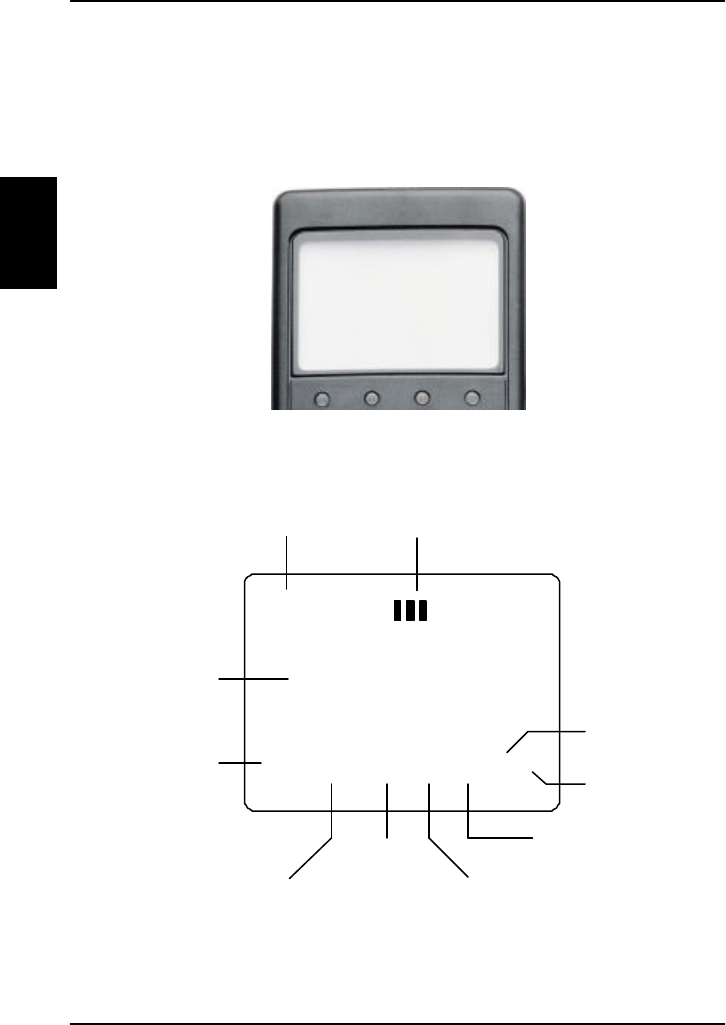
2.3.1. Display and LEDs
The following picture shows the top of the handset with
the display and LEDs. The LCD can be adjusted for
contrast and is backlit for viewing in dim light or at night.
The LCD display is graphically shown below:
Ready
AORE SB #1
Y
Z]^_`ab
Scroll Up
Text Area
Scroll Down
Secondary
Functions
Enabled
Locked
Alphabetic
Entry
Enabled
More Options
Available
Handset
Off Hook
Speaker
Enabled
Calls on
Hold
The Full Feature Handset Introduction
Dec 2003 23
2
The display contains a set of symbols which, together
with the 4 LEDs situated below the display, continuously
indicate the current status.
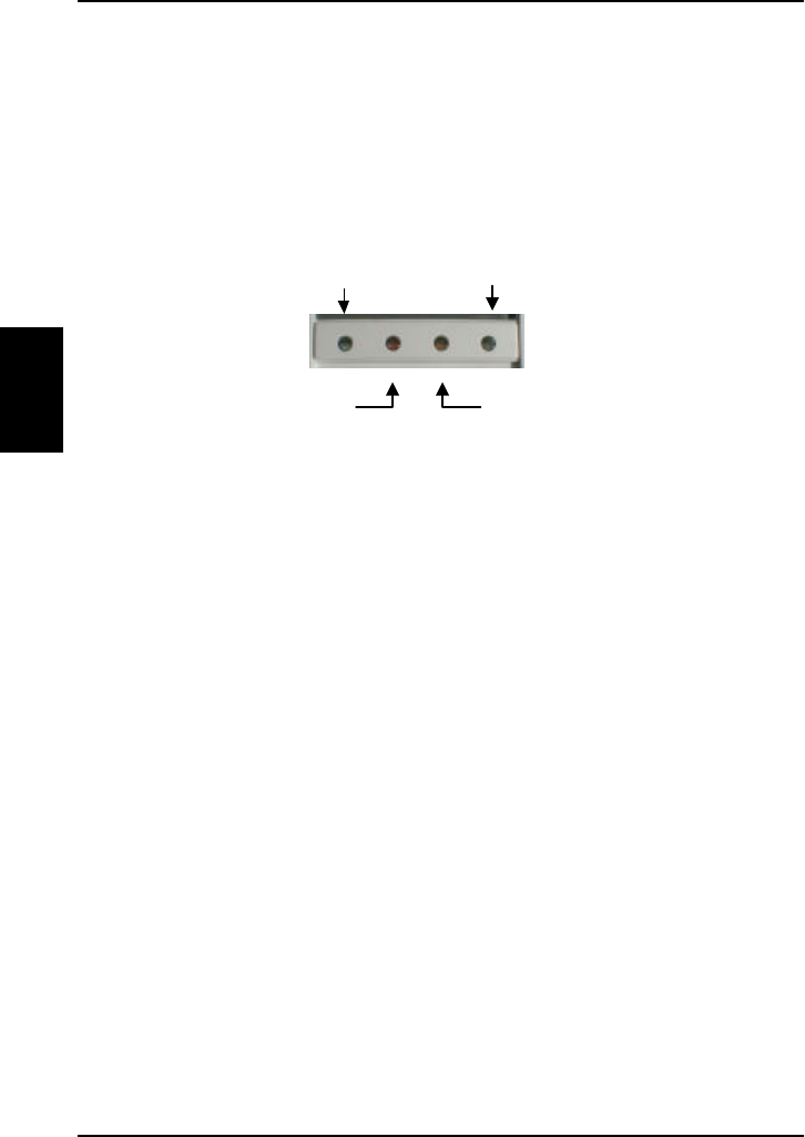
There are four LEDs below the LCD display.
• H+ LED (GREEN): The H+ LED indicates that the
system is logged on to H+ services.
• Alarm LED (RED): The Alarm LED illuminates when the
system detects a fatal or essential fault. A fault code is
also shown in the display.
• Connection LED (AMBER): The Connection LED flashes
when the handset is ringing. When a connection is
established the LED is turned off.
• HSD LED (GREEN): The HSD LED indicates that the
system is logged on to HSD services.
H+ HSD
Alarm Connection

Introduction The Full Feature Handset
24 Dec 2003
2
The below list shows the meaning of each of the various
symbols, that may appear in the display.
Symbol Meaning
Y More menu entries above.
Calls on hold. Each bar represents a call on
hold. Example: 3 bars=3 calls on hold.
Z More menu entries below.
] The G key has been pressed. The 2nd
function will be used for next button
pressed.
^ A valid pin code is required to use the
terminal.
_ The keypad is in alpha mode. Alpha mode is
used to enter letters (for example names in
the phone book).
Note: This symbol does not indicate capital
letters. The U button is used to toggle
the Caps lock function.
` The value in a menu must be selected
between certain predefined values by means
of the B and E keys.
a The speaker. You can turn the external
speaker on and off by pressing H. The a
symbol is displayed in the LCD when the
speaker is on.
b The handset is off hook
The Full Feature Handset Introduction
Dec 2003 25
2
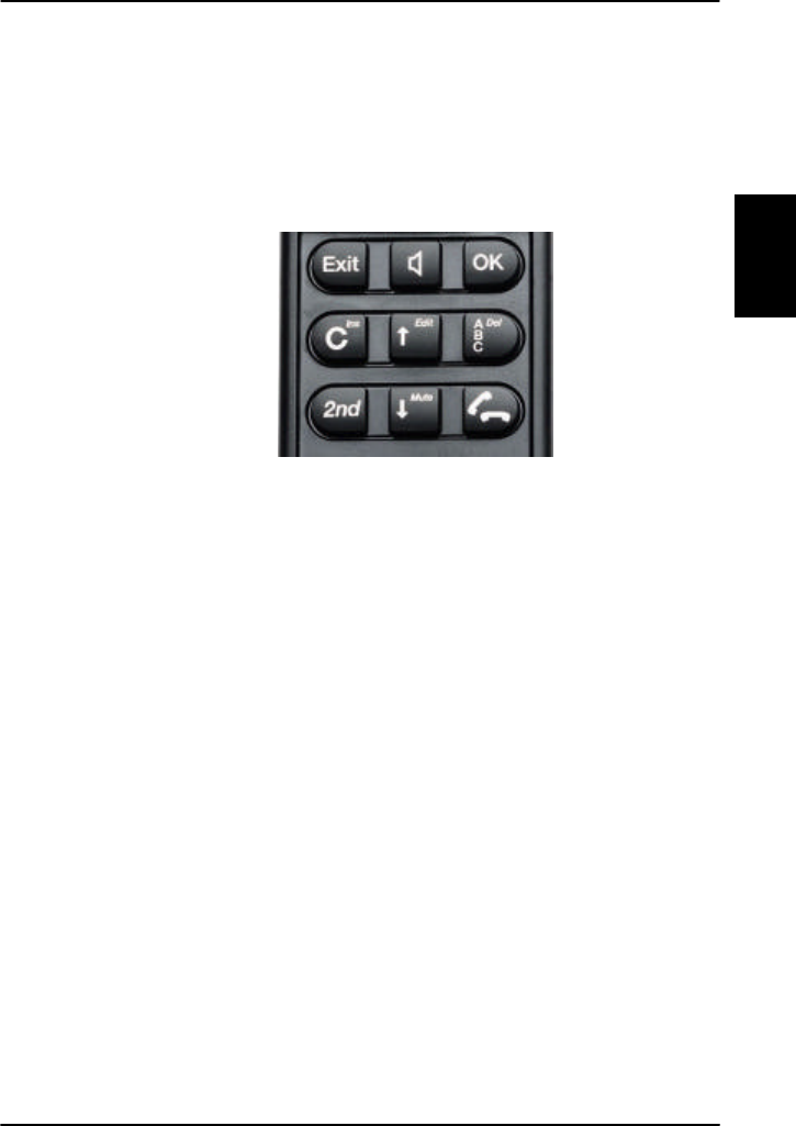
2.3.2. Function Buttons
The Function buttons enable you to enter the menu
system of the transceiver and change various settings.
Each button is described in detail on the following pages.

Introduction The Full Feature Handset
26 Dec 2003
2
Symbol Meaning
A Exit button:
• In the Menu system, pressing Exit brings
you back one level until the menu is
completely exited.
• When you are asked YES or NO by the
system, pressing Exit is interpreted as a
NO response.
• When you are entering data into the
transceiver, pressing Exit cancels the
entry.
H Speaker button: This button turns the
external speaker on and off.
C OK button:
• When in the main screen display,
pressing OK enters the menu system.
• When in the menu system, pressing OK
enters the selected menu.
• When entering data, such as phone
numbers or pin codes, pressing OK
applies the entry.
• When you are asked YES or NO by the
system, pressing OK is interpreted as a
YES response.
D Clear button: This is a dual function button.
The primary function is to clear the last
entered digit.
Secondary function: Insert. This function is
accessed by pressing G followed by D.
The insert function is used to insert new
phone book entries, etc.

The Full Feature Handset Introduction
Dec 2003 27
2
Symbol Meaning
B Scroll up button: Also a dual function button.
The primary function is to enable you to scroll
up to menu items not shown on the 2-line
display of the LCD.
Secondary function: Edit. Allows you to edit
previously entered information, for example
phone book entries.
F The primary function of this button is to
toggle between normal mode and alpha
numeric mode.
Secondary function: Delete. Allows you to
delete previously entered information, for
example phone book entries.
G The 2nd function of the next key pressed will
be applied.
E Scroll down button: The primary function is
to enable you to scroll down to menu items
not shown on the 2-line display of the LCD.
Secondary function: Mute turns the handset
microphone on/off.
I • When pressed after a number, I
initiates a call.
• When pressed during a phone call, I
ends the call.
• When pressed without a connection and
without any numbers entered, I
shows a list of the ten last dialled
numbers. When pressed again, I
dials the selected number.

Introduction The Full Feature Handset
28 Dec 2003
2
A number of keys have a 2nd function. The following table
gives a total overview of all the 2nd functions.
Key Function
GJ Enters the top level of the menu system.
GS Transfers the call to a specified handset.
GT Places a call on hold.
GU Joins other handsets to a call.
GD Inserts an entry, for example in the phone
book.
GB Edits an existing entry, for example in the
phone book.
GF Deletes an existing entry, for example in
the phone book.
GE Mute. Turns the handset microphone
on/off.
The Full Feature Handset Introduction
Dec 2003 29
2
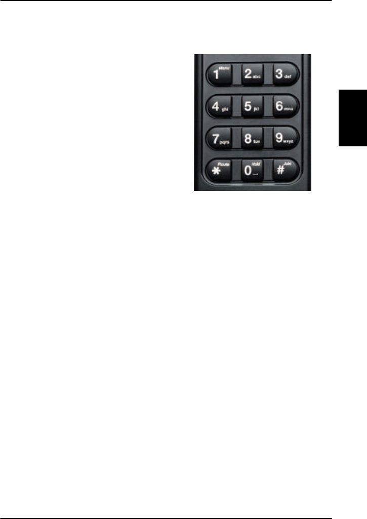
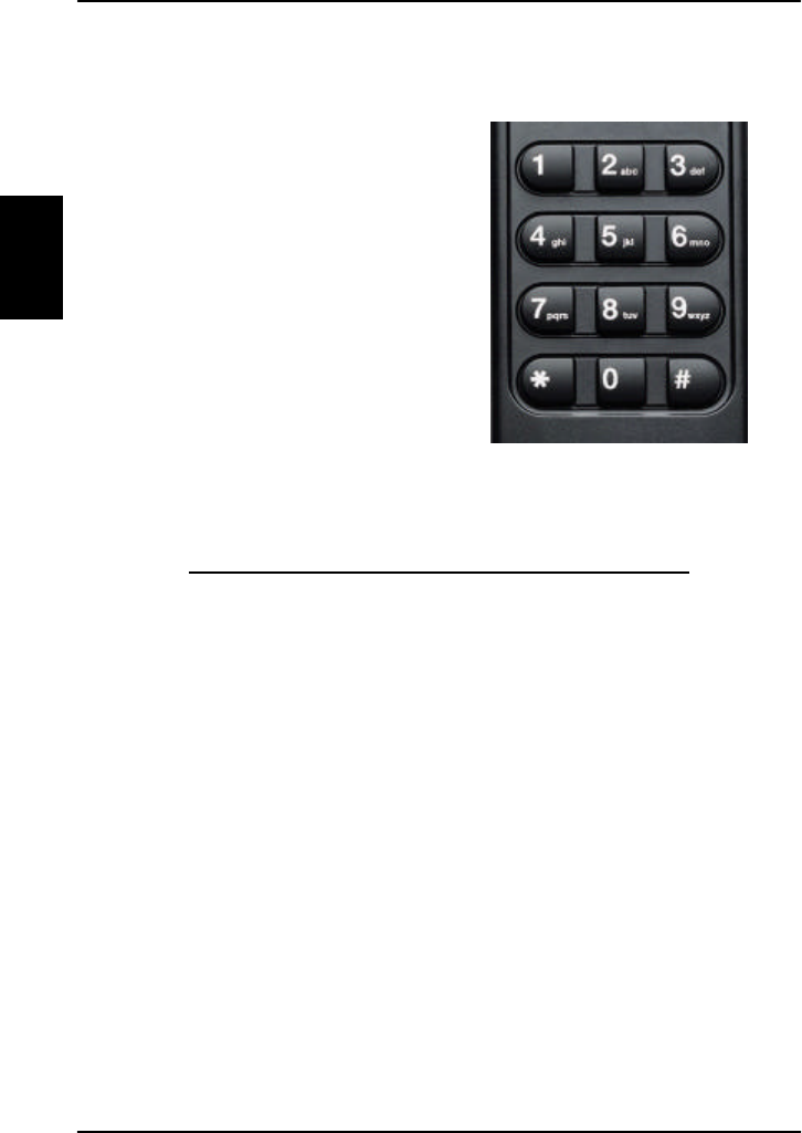
2.3.3. Alpha-Numeric Buttons
The keypad can be in
normal (numeric) mode or
alpha mode. Normal mode
is used to enter digits
(phone numbers) whereas
alpha mode is used to
enter letters (such as
names in the phone book).
The F button is used to
switch between the two
modes. The _ symbol in
the display indicates that
the handset is in alpha mode. In alpha mode you can use
each of the numeric keys and the U button to select
between subsets of the alphabet and certain special
characters.
To enter a character, press the key a number of times
until the wanted character is shown in the display. For
example, to insert the letter C, you press the K button
3 times in alpha mode. The U button is used as a Caps
lock toggle when the handset is in alpha mode.

Introduction The Full Feature Handset
30 Dec 2003
2
Below is an overview of the relevant keys in alpha mode.
Key Available characters or functions in alpha mode
J - ? ! , . : ’ $ ( ) + / 1
K A B C 2
L D E F 3
M G H I 4
N J K L 5
O M N O 6
P P Q R S 7
Q T U V 8
R W X Y Z 9
S Special function
T <space>
U Caps lock toggle
The Auxiliary Handset Introduction
Dec 2003 31
2
2.4. The Auxiliary Handset
The auxiliary handset provides an optional interface for
voice calls.
For information on how to use the auxiliary handset, see
Using the Auxiliary Handset on page 48.
The auxiliary handset is divided into the following 3
sections.
• The Light Emitting Diodes (LED) section. This section
gives you visual indications about the operation and
status of the system.
• The Function buttons section. This section gives you
access to a few call functions, such as transfer of
calls, memory etc.
• The Alpha-Numeric section. This section enables you
to dial numbers.

Introduction The Auxiliary Handset
32 Dec 2003
2
All 3 sections are explained in detail in the following
pages.
The auxiliary handset also provides a volume control
placed on the side of the handset.
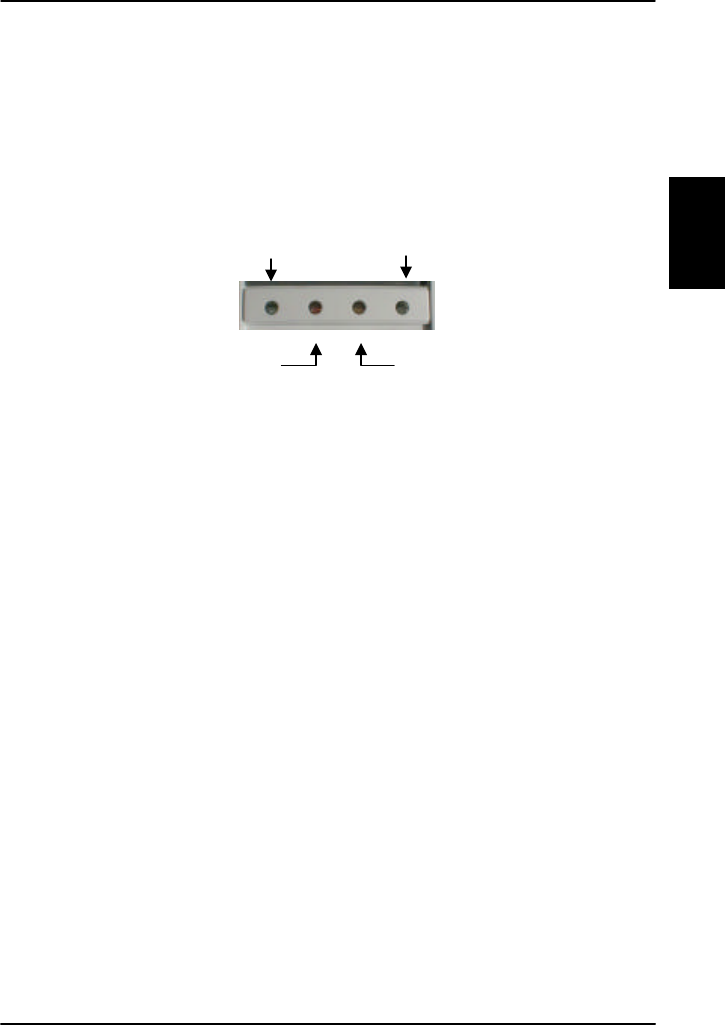
2.4.1. LEDs
There are two LEDs on the auxiliary handset.
The left green LED lights constantly when the handset is
off-hook.
The right green LED flashes to indicate that the handset
is ringing. When a connection is established, the LED is
turned off.
2.4.2. Function Buttons
The function buttons enable you to transfer calls, redial,
store and recall phone numbers, and mute the
microphone.

The Auxiliary Handset Introduction
Dec 2003 33
2
Each button is described in detail below.
Key Function
G Store number. This button is used to store
phone numbers.
H Memory. This button is used to recall phone
numbers from the memory.
F Transfer call. This button is used to transfer
an incoming call to another handset.
A Memory location 1.
(Same function as H J)
B Memory location 2.
(Same function as H K)
C Memory location 3.
(Same function as H L)
D Redial. This button is used to redial the last
dialled number.
E Mute. This button is used to mute the
microphone.
I Toggle hook. This button is used to toggle
between on-hook and off-hook.
Introduction The Auxiliary Handset
34 Dec 2003
2
2.4.3. Numeric Buttons
The numeric buttons are
primarily used to dial
numbers or to enter
numbers to be stored into
the memory.
Below is an overview of the relevant numeric keys.
Key Available Characters or Functions
J 1
K 2 a b c
L 3 d e f
M 4 g h i
N 5 j k l
O 6 m n o

The Auxiliary Handset Introduction
Dec 2003 35
2
Key Available Characters or Functions
P 7 p q r s
Q 8 t u v
R 9 w x y z
S Special function
T 0
U This button is used to indicate the end
of a phone number/activate a call.

Introduction Other Handset Types
36 Dec 2003
2
2.5. Other Handset Types
For information on other types of handset, see the User
Manual for the handset.
2.5.1. Sigma7 or 2.4 GHz Cordless phone
For information on how to make a call using the Sigma7
or 2.4 GHz Cordless phone, refer to the sections Using
the Sigma7 Handset on page 53 and Using the 2.4 GHz
Cordless Handset on page 54.
Initialising the System Getting started
Dec 2003 37
3
3. Getting started
3.1. Initialising the System
3.1.1. To Power on the System
The Aero-HSD+ system is powered by the aircraft power
system, and is powered up along with the aircraft.
The display and all LED's on the handset will light up for
a few seconds.
Below is an example of the normal readout of the
handset display, while the SDU is booting.
Initialising
Initialised
Handset #x
SelfTest
#x
LoggingOn
AORE #x
Wait for Nav
#x
LoggingOn
AORE SB #x
Ready
AORE #x
Getting started Initialising the System
38 Dec 2003
3
When the display shows “Ready”, the system is ready to
use.
The H+ LED indicates that H+ services are logged on,
and the HSD LED indicates that HSD services are logged
on.
Note: If the system does not log on automatically, the
reason may be that the Logon policy is set to User
Demand. In this case you have to log on using the Logon
menu. For further information, see Logon Menu on page
66.
3.1.2. To Power off the System
The system is automatically powered off along with the
aircraft.
Some aircrafts are provided with a “SatCom on/off”
button, which can be used to power off the system while
the aircraft is powered.
If the aircraft does not provide a “SatCom on/off” button,
you can use the circuit breaker to power off the system.
H+ HSD
Alarm Ringing

Pin Codes. Getting started
Dec 2003 39
3
3.2. Pin Codes.
For some of the functionality of the terminals, access is
restricted by a pin code. Three different kinds of user pin
codes are used in the system:
• one pin code for the Normal user,
• one for the Super User and
• one for the Service Provider.
Common for all pin code types is that the length must be
between 4 and 8 digits and that they contain digits
between 0 and 9.
Normal User Pin code
The normal everyday user can make and receive calls,
access the phone book, choose an ocean region and a
default LES and GES, and read the alarm log and status.
A Normal User will typically be the day-to-day user of the
system. All additional setup has to be carried out by a
Super User or a Service Provider.
Super User Pin code
The Super User has the same rights as the Normal User.
In addition, the Super User can access certain super user
functions. A Super User will typically be a person
responsible for setting up and maintaining the system.
Service Provider Pin code
The Service Provider has access to all functionality
accessible through the handset.
Only Thrane & Thrane and/or the supplier of the
equipment normally know this pin code.

Getting started Pin Codes.
40 Dec 2003
3
This page is intentionally left blank

Menu Navigation Operation
Dec 2003 41
4
4. Operation
4.1. Menu Navigation
This section describes how to access the menu system
using the buttons and display of the Full Feature
Handset.
To access the menus, press C or GJ.
When you are in the menu system you may also press
GJ to reach the top level of the menus.
To scroll through the menus, use the B and E keys.
To enter the selected menu, press C.
To go back to the previous level in the menu system,
press A.
To reach a specific item in the menu system, press
GJ and a number corresponding to the entry level.
Example: Press GJN to access the 'Logon' menu
(which is the 5th entry in the main menu).
There are 4 different levels of access to the menus:
• Users without a pin code
• Normal User
• Super User
• Service Provider.
The normal everyday functions can be used without
entering any pin codes.

Operation Menu Navigation
42 Dec 2003
4
The Normal User has access to normal everyday
functions and to make changes to these.
A Super User has the same rights as the Normal User,
but can additionally access a few extra settings that are
not available to the Normal User.
The Service Provider menu can only be accessed by the
supplier or Thrane & Thrane.
The Normal User, Super User and Service Provider menus
are protected by pin codes. You will be prompted for a
pin code when entering a function that is restricted by
pin codes.
The complete Menu Tree is found in Appendix A - Menu
Tree.
All the menus are described in The Menus on page 58.

Using the Full Feature Handset Operation
Dec 2003 43
4
4.2. Using the Full Feature
Handset
Any call made from the system uses one of the service
types H+ voice, ISDN or 3.1 kHz audio.
Before making a call, make sure the display shows
“Ready” and that the service LEDs (H+ and/or HSD) are
lit.
4.2.1. Making a H+ Call from the Handset
The service type used for a call from the handset is the
service type configured as default for this handset and
the LES or GES operator used will be the default LES or
GES operator.
To make a call from the Full Feature handset, type in
the phone number as if you were making an international
call (with the prefix 00 for automatic international calls).
Example: To dial the number of Thrane & Thrane
(+45 39558800), press the number:
TT for international calls, MN for country code,
then LRNNQQTT, followed by I, C
or U. The display on the terminal handset shows how
the call proceeds.
You hang up by pressing I. After hanging up, the
display shows the duration of the call.
Example:
The Phone Book can also be used to initiate a call, either
by selecting an entry in the phone book or by using the
Quick Dial function.
Connected:
00:01:59

Operation Using the Full Feature Handset
44 Dec 2003
4
4.2.2. Making a Call Using the Phone Book
The phone book can be used to initiate a call.
For information on how to insert or edit entries in the
phone book, see Phone Book on page 58.
To make a call using the phone book, do as follows:
1. Press B or E to access the phone book from
the main display, or enter the menu system and
select PhoneBook.
2. Find the entry you need, either by scrolling the list
with B or E, or by pressing F followed by the
first letter of the entry.
Example: To find an entry with the name Jones,
press F followed by N.
3. Press I, C or U to dial the selected number.
4.2.3. Using the Quick Dial Function
To use the Quick Dial function, press one of the J→
R keys and hold it down for 1 sec. Each key is a
shortcut to a user-defined entry in the phone book. For
further information, see the section QuickDial on page
78.
4.2.4. Redialling a Number
To call the last used number, press I to show a list of
the last ten numbers dialled from the handset. Scroll
through the list and press I, C or U to establish a
call to the selected number.
Using the Full Feature Handset Operation
Dec 2003 45
4
4.2.5. Making Internal Calls
It is possible to make internal calls between any of the
POTS phones and Full Feature handset interfaces.
To initiate an internal call, press the interface code in
the table below followed by U.
Note: The Interface Code is shown in the right bottom
corner of the display of the Full Feature Handsets.
Interf ace Interface Code
Full Feature Handset #1 1
Full Feature Handset #2 2
Full Feature Handset #3 3
Full Feature Handset #4 4
POTS phone #1 5
POTS phone #2 6
Example: To call Full Feature Handset number 3, press
L U.
To make an internal call to all handsets,
press S S T U

Operation Using the Full Feature Handset
46 Dec 2003
4
4.2.6. Transferring a Call
It is possible to receive a call on a handset and transfer
the call to another handset.
Use the following procedure to make a Call transfer:
1. When an incoming call is received, answer the call
as usual with I or simply lift the handset from the
cradle.
2. Place the call on hold with GT.
3. Dial the Interface Code of the desired handset, e.g.
K for Handset #2.
4. Initiate handset to handset call with U.
You have now established an active call from
handset to handset, and you can give a short
message.
5. Route the incoming call to the new handset with
GS, or by just placing the handset in the cradle.

Using the Full Feature Handset Operation
Dec 2003 47
4
4.2.7. Making a Conference Call
It is possible to make conference calls between more
handsets.
Use the following procedure to make a Conference Call.
4. When a call is already established, place the call on
hold with GT.
5. Dial the desired handset e.g. K for handset #2.
6. Initiate handset to handset call with U.
7. Join all three handsets with G U.
To join more handsets, repeat step 1 to 4.

Operation Using the Auxiliary Handset
48 Dec 2003
4
4.3. Using the Auxiliary Handset
4.3.1. Making a Call
Making a call from a normal 2-wire POTS phone
connected to one of the two analogue POTS phone
interfaces is done in the same way as a call from a
standard telephone. Just remember to press the U-key
after the number to signal to the terminal, that the
number is complete.
Example: To call Thrane & Thrane in Denmark (country
code 45) first establish a connection by pressing I or
taking the handset off the cradle. Then press the
following keys on the phone:
TTMNLRNNQQTTU
Internal calls are made the same way as with the Full
Feature handset. For information on how to make an
internal call between the handsets, see Making Internal
Calls on page 45.

Using the Auxiliary Handset Operation
Dec 2003 49
4
4.3.2. Storing a Phone Number
The auxiliary handset can store up to 10 phone numbers,
in memory location 0 to 9. The A, B and C keys can
be used for accessing memory location 1, 2 and 3,
whereas the other locations are accessed using the MEM
key followed by the number of the location.
To store a phone number in the memory using the A,
B and C keys, do as follows:
1. Press I or take the handset off the cradle.
2. Press G.
3. Enter the phone number you want to store,
including country code.
4. Press G.
5. Press A, B or C depending on the memory
location you want to save the number in.
The number is now available in the memory location
you selected.
Example: To save the phone number of Thrane &
Thrane in memory location 2, take the handset off the
cradle and press the following keys:
G
TTMNLRNNQQTT
G
B

Operation Using the Auxiliary Handset
50 Dec 2003
4
To store a phone number in the memory using the
number keys, do as follows:
1. Press I or take the handset off the cradle.
2. Press G.
3. Enter the phone number you want to store,
including country code.
4. Press G.
5. Press one of the keys 0 to 9, depending on the
memory location you want to save the number in.
The number is now available in the memory location
you selected.
Example: To save the phone number of Thrane &
Thrane in memory location 8, take the handset off the
cradle and press the following keys:
G
TTMNLRNNQQTT
G
Q

Using the Auxiliary Handset Operation
Dec 2003 51
4
4.3.3. Recalling a Phone Number from
Memory
To recall a phone number from memory location 1, 2 or 3
using the A, B and C keys, do as follows:
1. Press I or take the handset off the cradle.
2. Press A, B or C, depending on which memory
location you want.
The number saved in the memory location is dialled.
Example: To call the number saved in memory location
3, first establish a connection by pressing I or taking
the handset off the cradle. Then press C. The number
saved in memory location 3 is dialled.
To recall a phone number from memory using the H
key, do as follows:
3. Press I or take the handset off the cradle.
4. Press H followed by the number of the memory
location you want.
The number saved in the memory location is dialled.
Example: To call the number saved in memory location
8, first establish a connection by pressing I or taking
the handset off the cradle. Then press H Q. The
number saved in memory location 8 is dialled.
Note: Pressing A has the same effect as pressing
H J.

Operation Using the Auxiliary Handset
52 Dec 2003
4
4.3.4. Transferring a Call
It is possible to receive a call on a handset and transfer
the call to another handset.
Use the following procedure to make a Call transfer:
6. When an incoming call is received, answer the call
as usual with I or simply lift the handset from the
cradle.
7. Place the call on hold with F.
8. Dial the Interface Code of the desired handset, e.g.
K for Handset #2.
9. Initiate handset to handset call with U.
You have now established an active call from
handset to handset, and you can give a short
message.
10. Route the incoming call to the new handset by
pressing I, or placing the handset in the cradle.
4.3.5. Redialling a Number
To call the last dialled number, first establish a
connection by pressing I or taking the handset off the
cradle. Then press D followed by U.
4.3.6. Muting the Microphone
To mute the microphone of the handset, press E. To
return to normal microphone function, press E again.

Using the Sigma7 Handset Operation
Dec 2003 53
4
4.4. Using the Sigma7 Handset
4.4.1. Making a Call
To make a call using the Sigma7 handset, type in the
phone number as if you were making an international call
(with the prefix 00 for automatic international calls), and
press the “On” key.
Example: To dial the number of Thrane & Thrane
(+45 39558800), press the number:
“00” for international calls, “45” for country code,
then “39558800”, followed by the “On” key.
To hang up, press the “Off” key or place the handset in
the cradle.
To answer a call, press the “On” key.
For further information on the functions of the Sigma7
handset, refer to:
“Sigma7 Telephone Handset Manual”, PN# 500114

Operation Using the 2.4 GHz Cordless Handset
54 Dec 2003
4
4.5. Using the 2.4 GHz Cordless
Handset
4.5.1. Making a Call
To make a call using the 2.4 GHz Cordless handset, type
in the phone number as if you were making an
international call (with the prefix 00 for automatic
international calls), and press the “TALK” key.
Example: To dial the number of Thrane & Thrane
(+45 39558800), press the number:
“00” for international calls, “45” for country code,
then “39558800”, followed by the “TALK” key.
To hang up, press the “END” key or place the handset in
the cradle.
To answer a call, press the “TALK” key.
For further information on the functions of the 2.4 GHz
Cordless handset, refer to:
“2.4 GHz Cordless, Installation Manual”, PN# 500484

Other Call Functions Operation
Dec 2003 55
4
4.6. Other Call Functions
4.6.1. Making a Call from an ISDN Phone
Making a call from a phone connected to the ISDN
interface is similar to making a call from the POTS
handset, that is, you have to press U to indicate the
end of the number.
Example: To call Thrane & Thrane in Denmark (country
code 45) first establish a connection by pressing I.or
taking the handset off the cradle. Then press the
following keys on the phone:
TTMNLRNNQQTTU
4.6.2. Sending a Fax Using H+
Important: Before sending or receiving fax messages,
make sure the ground fax unit is in “Overseas” mode.
Your installation determines whether your fax unit uses
H+ or HSD.
To send a fax from one of the two analogue POTS phone
interfaces, use the prefix 01 followed by the called fax
number including the country code, followed by U.
Example: To call Thrane & Thrane in Denmark (country
code 45) press the following keys on the fax:
mcfgekggjjjjn

Operation Other Call Functions
56 Dec 2003
4
4.6.3. Sending a Fax Using HSD
Important: Before sending or receiving fax messages,
make sure the ground fax unit is in “Overseas” mode.
Your installation determines whether your fax unit uses
H+ or HSD.
To send a fax using HSD (e.g. via ISDN)::, use the prefix
00 followed by the called fax number including the
country code, followed by U.
Example: To call Thrane & Thrane in Denmark (country
code 45) press the following keys on the fax
mmfgekggjjjjn

Other Call Functions Operation
Dec 2003 57
4
4.6.4. Calling the Terminal
Calling the terminal or a device connected to the terminal
is similar to making international calls. The specific
Inmarsat Mobile Number (IMN)1 has to be preceded by
one of the five possible international access codes. This
code depends on whether you know which area the
terminal is within or not:
870: Area of terminal not known
(Requires that the LES or GES supports Mobility
Management).
871: AORE
872: POR
873: IOR
874: AORW
To call the IMN-number on a terminal situated in IOR, dial
+873 followed by the IMN number (where the “+” stands
for the IDD (International Direct Dialing) Prefix – which is
00 for many countries).
The different IMN numbers can be obtained from the ISP.
1 A terminal may have more IMN numbers, as different
services exist and more devices may be connected to the
different hardware interfaces of the terminal.
Operation The Menus
58 Dec 2003
4
4.7. The Menus
This section describes each of the menus in the system.
For an overview of all the menus, see Appendix A - Menu
Tree.
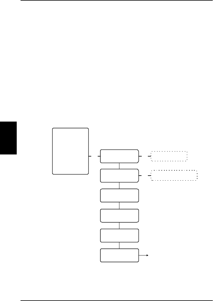
4.7.1. Phone Book
The Phone Book contains 99 entries, which can be used
for making phone calls. You can edit, delete or insert
entries.
To access the Phone Book menu, you can:
• press B or E from the main display, or
• press C to enter the main menu, scroll to Phone
Book and press C.
Each entry holds the following information:
• Name
• Telephone number
Enter name Enter number
Call selected number
DeleteEntry?
<Entry > Entry is deleted
Edit / Ins
Del
ABC
Toggle display between
name and number
Toggle between
phone numbers
OK
OK
OK
OK
Phone Book
HandsetSetup
Ring Profile
Lock System
Logon Menu
System Setup
Status

The Menus Operation
Dec 2003 59
4
The telephone number must include call prefix for
automatic calls and international access code. The
telephone number can hold up to 24 digits.
The name can hold up to 24 characters.
The list of entries in the phone book is sorted
alphabetically.
An entry in the phone book is displayed as a name if in
alpha mode or as a telephone number if in normal mode.
To dial from the phonebook, use BE to select an
entry and press C, I or U to dial.
Hint: You may also go directly to a specific entry by
pressing F followed by the first letter of the entry.
To insert a new entry in the phone book, do as follows:
1. From within the Phone Book menu, press GD
and enter the name of the new entry followed by
C.
2. Enter the phone number including country code and
press C.
Example: In this example the number to Thrane &
Thrane, 004539558800, is inserted.
GD
THRANEC
TTMNLRNNQQTT
C
You edit or delete an entry by selecting the entry in the
phone book and pressing GB or GF
respectively.

Operation The Menus
60 Dec 2003
4
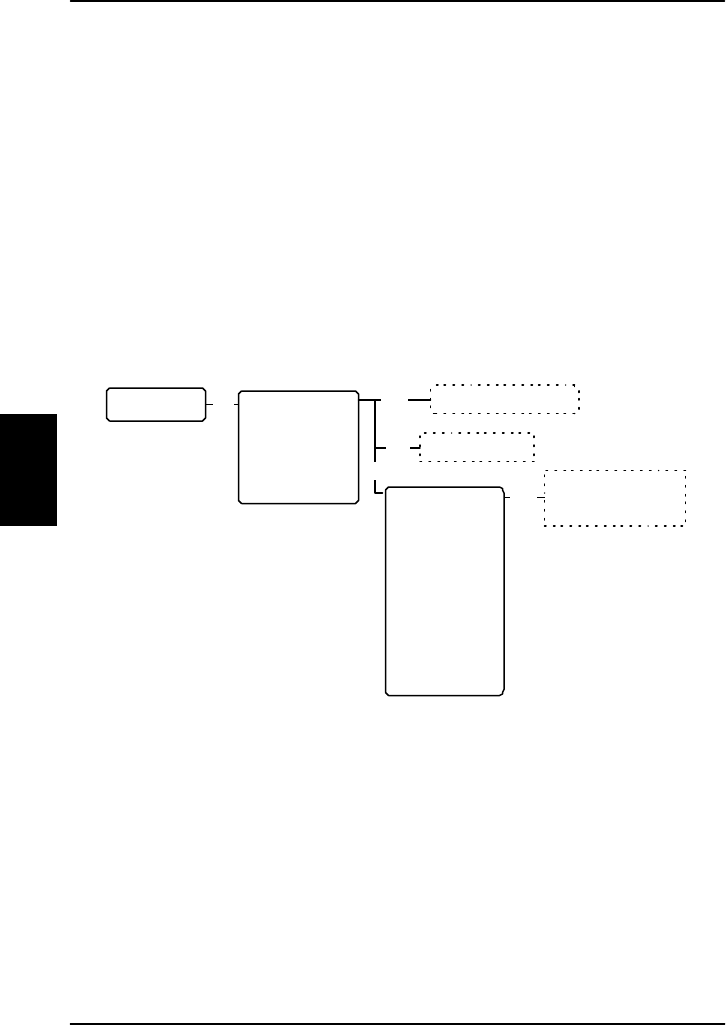
4.7.2. HandsetSetup
The HandsetSetup menu is used for adjusting the light
and sound settings of the handset.
The HandsetSetup menu has the following submenus:
• Silent
• Contrast
• Light
• Key Beep
• Single Ring
• Common Ring
• Ring Volume
• Phone Volume
• ComfortNoise
Each of the submenus is described in the following
pages.
The Menus Operation
Dec 2003 61
4
To access the HandsetSetup menu, enter the main menu,
scroll down to HandsetSetup and press C.
Toggle between 1 to 8 *
Toggle between Auto,
On, Off and All off
Toggle between
Off and 1 to 4 *
Toggle between 8
predefined ringtones
Toggle between 8
predefined ringtones
Toggle between 1 to 4 *
Toggle between
Off and 1 to 3 *
Phone Book
HandsetSetup
Ring Profile
Lock System
Logon Menu
System Setup
Status
Toggle between
Enabled and Disabled
Toggle between 1 to 8 *
OK
Contrast
Light
Key Beep
Single Ring
Common Ring
Ring Volume
ComfortNoise
Silent
Phone Volume
OK
OK
OK
OK
OK
OK
OK
OK
OK
Operation The Menus
62 Dec 2003
4
Silent: Select Silent to view or change the Silent setting
of the handset.
Use B and E to toggle between Enabled and
Disabled. Enabled turns off the ring tone of the handset.
Contrast: Select Contrast to view or change the contrast
setting of the handsets.
Use B and E to adjust the contrast and C to
confirm.
The value can be between * and ********.
Light: Select Light to view or change the light setting of
the handsets.
Use B and E to scroll between the settings and C
to confirm..
The value can be Auto | On | Off | All Off.
The following table shows the function of the light
settings.
Setting Display Backlight LEDs
Auto Activated on event Normal function
On Always on Normal function
Off Always off Normal function
All Off Always off Always off

The Menus Operation
Dec 2003 63
4
Key Beep: (A “beep” sound when a key is pressed).
Select Key Beep to view or change the Key Beep setting
of the handsets.
Use B and E to adjust the Key Beep and C to
confirm..
The value can be Off or between * and ****.
Single Ring (Direct call ring tone): Select Single Ring to
view or change the ring tone setting of the current
handset.
Use B and E to scroll through the ring tones and C
to select.
You can choose between 8 predefined ring tones.
Common Ring (Broadcast call ring tone): Select Common
Ring to view or change the common ring tone setting of
all the handsets.
Use B and E to scroll through the ring tones and C
to select.
You can choose between 8 predefined ring tones.
Ring Volume: Select Ring Volume to view or change the
Ring Volume setting of the handset.
Use B and E to adjust the Ring Volume and C to
confirm.
The value can be Off or between * and ****.

Operation The Menus
64 Dec 2003
4
Phone Volume: Select Phone Volume to view or change
the Volume setting for the phones.
Use B and E to adjust the Phone Volume and C to
confirm.
The value can be Off or between * and ****.
ComfortNoise: (A background noise to verify that the
line is connected). Select ComfortNoise to view or change
the Comfort Noise setting of the handset.
Use B and E to adjust the Comfort Noise and C to
confirm.
The value can be Off or between * and ***.

The Menus Operation
Dec 2003 65
4
4.7.3. Ring Profile
The Ring Profile menu allows you to select from a list of
predefined ring profiles. A ring profile applies to the
entire system and determines the ring settings of each
unit in the system.
To access the Ring Profile menu, enter the main menu,
scroll down to Ring Profile and press C.
Use B and E to scroll through the ring profiles and
C to select.
Note: If the "Chime/Lamps Inhibit" function is used in
the installation, the "TakeOfLandng" profile is
automatically activated during takeoff and landing.
For information on how to change the ring profiles, see
the section System Setup on page 73.
4.7.4. Lock System
The Lock System menu can be used to lock the phone.
Do as follows:
To lock the phone, enter the main menu, scroll down to
Lock System, press C and enter the Normal User Pin
code.
To unlock the phone, press C and enter the Normal
User Pin code.
Operation The Menus
66 Dec 2003
4
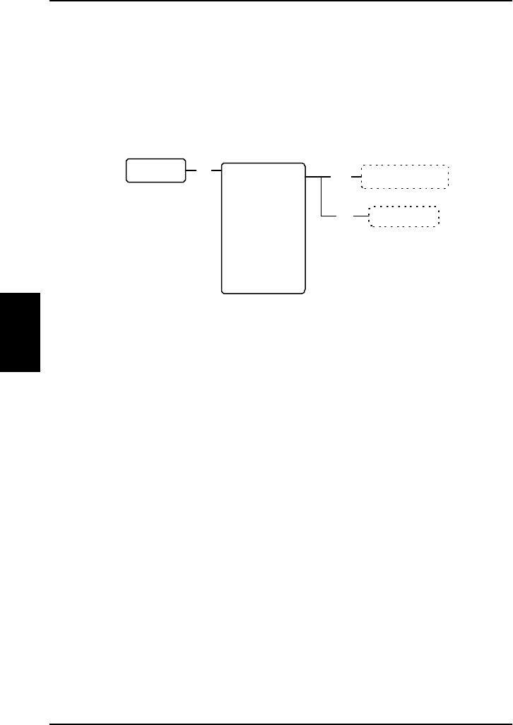
4.7.5. Logon Menu
The Logon Menu is used to log on or off the system, or
to change the Logon settings.
The Logon Menu has the following sub menus:
• Manual Logon
• Custom Logon
• Auto Logon
• Renew Logon
• Logoff
• Settings (see Settings on page 68)
To access the Logon Menu, enter the main menu, scroll
down to Logon Menu and press C.
OK
Custom Logon
Auto Logon
Renew Logon
Logoff
Settings
Manual Logon
OK
OK Scroll through the
list of known GESs
Enter Sat-ID and GES-ID
See Settings submenu
Phone Book
HandsetSetup
Ring Profile
Lock System
Logon Menu
System Setup
Status

The Menus Operation
Dec 2003 67
4
Manual Logon:
Note: Before logging on manually, make sure the Logon
Policy is set to User Demand. To change the Logon Policy,
select Settings from the Logon menu and then Logon
Policy. You can toggle between User Demand and
Automatic and select with C.
Select Manual Logon to select the GES manually from the
list of known GESs.
Use B and E to scroll through the list and C to
select.
Custom Logon:
Note: Before making a Custom Logon, make sure the
Logon Policy is set to User Demand. To change the Logon
Policy, select Settings from the Logon menu and then
Logon Policy. You can toggle between User Demand and
Automatic and select with C.
Select Custom Logon to manually enter the Sat-ID and
GES-ID you want to use for logging on.
For instance, you can use this menu if you need to log on
to a GES which is not in the list of known GESs.
Enter the Sat-ID and GES-ID and press C to confirm.
Auto Logon: Select Auto Logon to log on automatically to
the most appropriate GES.
Renew Logon: Select Renew Logon to log off and then
on again.
Logoff: Select Logoff to log off the system.
To log on again you have to use the logon menu.
Settings: See the section Settings on page 68.

Operation The Menus
68 Dec 2003
4
Settings
From the Settings submenu you can change the logon
policy and view or change the lists of preferred GESs and
LESs.
The Settings menu has the following sub menus:
• Logon Policy
• H+ GES
• ISDN LES
• MPDS LES
Each of the submenus is described in the following
pages.

The Menus Operation
Dec 2003 69
4
To access the Settings submenu, enter the Logon Menu,
scroll down to Settings and press C.
Settings OK Logon Policy
H+ GES
ISDN LES
MPDS LES
Toggle between
Automatic and
User Demand
OK
Scroll through
list of
preferred GESs
OK Scroll through
list of preferred
LESs for ISDN
OK
Scroll through
list of preferred
LESs for MPDS
OK Scroll and
select from list
of known GESs
Ins
Del
GES is deleted
Use up/down
keys to change
priority
Edit
Scroll and
select from list
of known LESs
Ins
Del LES is deleted
Use up/down
keys to change
priority
Edit
Scroll and
select from list
of known LESs
Ins
Del LES is deleted
Use up/down
keys to change
priority
Edit
Use * key to set
the same priority
as GES below

Operation The Menus
70 Dec 2003
4
Logon Policy: Select Logon Policy to display or change
the logon policy.
Use B and E to toggle between Automatic and User
Demand.
• Automatic: The system automatically logs on when
it is powered up.
• User Demand: When the system is powered up you
have to enter the Logon menu to log on to the
system.
H+ GES: Select H+ GES to view or change the list of
preferred GESs for H+ transmission.
The H+ GES list is a list of the preferred GES operators to
use as gateway to the terrestrial network.
Important: If you are using the list of preferred GESs
you must always select at least one GES from each
Ocean region with top priority, i.e. with the same priority
as the GESs of the other ocean regions.
1. To add a GES to the list, press GD, scroll
through the list of known GESs and use C to
select the GES you want to add.
2. To delete a GES from the list, scroll to the GES you
want to delete and press GF.
3. To change the priority of a GES, scroll to the GES
you want to change and press GB.
Use B or E to move the GES to the right
priority.
Note: Priority no. 1 is the highest priority!
4. To assign the same priority to two GESs, do as
follows:

The Menus Operation
Dec 2003 71
4
• Scroll to the GES you want to change and press
GB.
• Move the GES to just above the GES with the
priority you want.
• Press GB followed by S.
The two GESs should now have the same
priority.
ISDN LES: Select ISDN LES to view or change the list of
preferred LESs for ISDN transmission.
The ISDN LES list is a list of the preferred LES operators
to select as gateway to the terrestrial network.
1. To add a LES to the list, press GD, scroll
through the list of known LESs and use C to
select the LES you want to add.
2. To delete a LES from the list, scroll to the LES you
want to delete and press GF.
3. To change the priority of a LES, scroll to the LES
you want to change and press GB.
Use B or E to move the LES to the right priority.
Note: Priority no. 1 is the highest priority!

Operation The Menus
72 Dec 2003
4
MPDS LES: Select MPDS LES to view or change the list
of preferred LESs for MPDS transmission.
The MPDS LES list is a list of the preferred LES operators
to select as gateway to the terrestrial network
1. To add a LES to the list, press GD, scroll
through the list of known LESs and select the LES
you want to add.
2. To delete a LES from the list, scroll to the LES you
want to delete and press GF.
3. To change the priority of a LES, scroll to the LES
you want to change and press GB. Then use
B or E to move the LES to the right priority.

The Menus Operation
Dec 2003 73
4
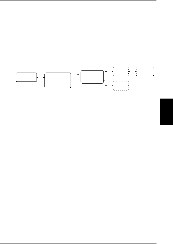
4.7.6. System Setup
The System Setup menu is used for viewing and
changing system parameters such as ring profiles, pin
codes etc.
The System Setup menu has the following submenus:
• Ring Profiles (see RingProfiles on page 76)
• QuickDial (see QuickDial on page 78)
• Disclose Pos
• Fax Setup
• Pin Setup (see Pin Setup on page 79)
• Configure (see Configure on page 80)
Each of the submenus is described in the following
pages.

Operation The Menus
74 Dec 2003
4
To access the System Setup menu, enter the main menu,
scroll down to System Setup and press C.
Toggle between
Enabled and Disabled
RingProfilesOK
OK
See RingProfiles submenu
See QuickDial submenu
See Pin Setup submenu
See Configure submenu
QuickDial
Disclose Pos
Pin Setup
Configure
Super User
Pin Code
Phone Book
HandsetSetup
Ring Profile
Lock System
Logon Menu
System Setup
Status
Fax Setup OK Fax Interface
Toggle between
Not Connected,
POTS #1,
POTS #2 and
POTS #1 & #2

The Menus Operation
Dec 2003 75
4
Disclose Pos: Select Disclose Pos to view or change the
Disclose Position status.
Note: A Super User pin code is required to change the
Disclose Position status.
Use B and E to toggle between Enabled and
Disabled.
If you select Enabled, the position of the aircraft will be
disclosed to the earth station for use in the Inmarsat
network.
If you select Disabled, only the ID of the current spot
beam is disclosed.
Fax Setup: Select Fax setup to determine which interface
should not ring on a broadcast call.
Use B and E to scroll through the interface options
and select with C.
You may select:
• POTS #1
• POTS #2
• POTS #1 & #2, or
• Not Connected
Operation The Menus
76 Dec 2003
4
RingProfiles
The RingProfiles submenu is used to view or change the
Ring Profiles of the system. You can have up to 5 ring
profiles. One of the profiles “TakeOfLandng”, is
predefined.
Note: If the "Chime/Lamps Inhibit" function is used in
the installation, the "TakeOfLandng" profile is
automatically activated during takeoff and landing.
To access the RingProfiles submenu, enter the System
Setup menu, scroll down to RingProfiles and press C.
To change the name of a profile, scroll to the profile,
press GB and enter the new name.
To change the contents of a profile, do as follows:
1. Select the profile using C.
2. Scroll to the device you want to change the
settings for, and select it with C.
OK
Edit
Toggle between "User
control", "Ringer on"
and "Ringer off"
Enter new Profile name
RingProfiles 1 <empty>
2 <empty>
3 <empty>
4 <empty>
TakeOfLandng
Edit
Handset #1
Handset #2
Handset #3
Handset #4
POTS #1
POTS #2
ISDN
Annunciator1
Annunciator2
Annunciator3
OK
Entry is deleted
Del

The Menus Operation
Dec 2003 77
4
3. Use B and E to toggle between User Control,
Ringer On and Ringer Off.
Note: “User Control” is only applicable to
Handset #1 through #4. This means you can
configure each of the handsets #1 through #4
separately. For the remaining devices, “User
Control” has the same function as “Ringer On”.
To delete a profile, scroll to the profile you want to
delete and press GF.
Below is an explanation of the Annunciators:
Annunciator1 (Call Annunciator): This Annunciator is used
for signalling incoming voice calls. The Annunciator is
"flashing" like the Connection LED on a 4-wire handset
and is turned of when the call is answered or terminated
by initiator.
Annunciator2 (Fax Annunciator): This Annunciator is used
for signalling incoming faxes. The Annunciator is "steady
ON" until a receipt for the fax has been given in the
handset.
Annunciator3 (Service Annunciator): This Annunciator is
used for indicating service availability. The Annunciator is
"steady ON" when H+ service is available.
Operation The Menus
78 Dec 2003
4
QuickDial
The QuickDial submenu is a list of 1-digit numbers for
quick dialling of up to 9 favourite phone numbers.
To access the QuickDial submenu, enter the System
Setup menu, scroll down to QuickDial and press C.
Toggle between All
Phone book entries
Delete entryDel
QuickDial 1 <empty>
2 <empty>
3 <empty>
4 <empty>
5 <empty>
6 <empty>
7 <empty>
8 <empty>
9 <empty>
OK Edit
To edit a quick dial entry, do as follows:
1. Scroll to the quick dial number you want to change
and press GB.
2. Scroll through the phonebook to the phone number
you want to use with the selected quick dial
number.
3. Press C to select the phone number.
To delete a quick dial entry, scroll to the quick dial
number you want to delete and press GF .
The Menus Operation
Dec 2003 79
4
Pin Setup
The Pin Setup submenu is used for disabling or
changing Pin codes.
To access the Pin Setup submenu, enter the System
Setup menu, scroll down to Pin Setup and press C.
To access the pin codes you want to change or disable,
do as follows:
1. Scroll to the pin code type you want to change or
disable
2. Enter the current pin code for the selected type.
3. Toggle between Change Pin and Disable Pin and use
C to select the function.
Change Pin: Choosing Change Pin you will be prompted
for a new Pin code. Enter a new Pin code of 4 to 8 digits
and use C to accept the code. When you are prompted
to re-enter the Pin code, enter the code again and
accept with C.
Disable Pin: Select Disable Pin to disable the Pin code
you entered. Press C to confirm the deletion.
Pin Setup OK Change Pin
Disable Pin
OK
Enter new
Pin Code Repeat new
Pin Code
OKOK
Press OK
to confirm
OK
NormalUsrPin
SuperUserPin
ServPrvdrPin
Enter
Pin Code

Operation The Menus
80 Dec 2003
4
Configure
The Configure submenu is used for configuring the
handset type and the lists of known GESs, LESs and
satellites.
Note: A Service Provider pin code is required to access
the settings in the Configure menu.
The Configure menu has the following submenus:
• Handset Type
• Known GESs
• Known LESs
• Init Sat
Each of the submenus is described in the following
pages.

The Menus Operation
Dec 2003 81
4
To access the Configure submenu, enter the System
Setup menu, scroll down to Configure and press C.
Configure Handset Type
OK
Known GESs
Known LESs
Init Sat
Scroll through the
list of known GESs
OK
OK
Scroll through the
list of known LESs
OK
OK
Sat #1
Sat #2
Sat #3
Sat #4
Spare #1
Spare #2
Spare #3
Spare #4
Edit/Ins
Del
Edit
Handset #1
Handset #2
Handset #3
Handset #4
Toggle between TT-Handset,
Headset and Not in Use
Edit
GES is deleted
Enter Sat Id, GES
Id, GES Code and
GES Name
Edit/Ins
Del LES is deleted
Enter LES Access Code
and LES Name
OK
Satellite Id
Longitude
P-Channel #1
P-Channel #2
Enter
new value
Service Provider
Pin Code

Operation The Menus
82 Dec 2003
4
Handset Type: Select Handset Type to view or change
the type of the handsets.
Use B and E to scroll through the list of handsets.
To change the handset type, select the handset you
want to change and press GB. Use B and E to
scroll between TT-Handset, Headset and Not in Use, and
press C to select.
Note: The Headset selection is only for future use.
Known GESs: Select Known GESs to view or change the
list of known GESs.
1. To add a GES to the list, press GD and enter:
Satellite ID, followed by C
GES ID, followed by C
GES Code, followed by C
GES Name , followed by C
2. To delete a GES from the list, scroll to the GES you
want to delete and press GF.
3. To edit a GES, scroll to the GES you want to change
and press GB. Enter:
Satellite ID, followed by C
GES ID, followed by C
GES Code, followed by C
GES Name , followed by C

The Menus Operation
Dec 2003 83
4
Known LESs: Select Known LESs to view or change the
list of known LESs.
1. To add a LES to the list, press GD, and enter:
LES Access (the Global LES Access Code), followed
by C
LES Name, followed by C
2. To delete a LES from the list, scroll to the LES you
want to delete and press GF.
3. To edit the LES information, scroll to the LES you
want to change and press GB. Enter:
LES Access (the Global LES Access Code), followed
by C
LES Name, followed by C
Init Sat: Select Init Sat to view or change the list of
satellites.
1. To edit the satellite information, scroll to the
satellite you want to change and press C. Enter:
Satellite ID, followed by C
Longitude, followed by C
The frequency for P-Channel #1, followed by C
The frequency for P-Channel #2, followed by C
2. To delete a satellite from the list, scroll to the
satellite you want to delete and press GF.

Operation The Menus
84 Dec 2003
4
4.7.7. Status
The Status submenu is used for viewing signal strength,
LAN status, navigation data, active errors, serial numbers
and software versions.
The Status menu has the following submenus:
• Channels
• Nav data
• SDU
• SW version
• LAN
• Active Error
Each of the submenus is described in the following
pages.
The Menus Operation
Dec 2003 85
4
To access the Status menu, enter the main menu, scroll
down to Status and press C.
ChannelsOK
Nav Data
SDU
SW Version
LAN
Active Error
OK
Latitude
Longitude
Altitude
Speed
Nav Source
IRS Active
AHRS Active
GPS Active
Show Detailed Nav
Show Antenna Pos
PRT
C1
C2
HSD
OK
Heading
Pitch
Roll
Doppler Vel
OK
Serial No.
ISN
ICAO
OK
Main
Handset 1
Handset 2
Handset 3
Handset 4
OK
Scroll through a list
of active errors
OK
Phone Book
HandsetSetup
Ring Profile
Lock System
Logon Menu
System Setup
Status

Operation The Menus
86 Dec 2003
4
Channels: Select Channels to display the signal strength
(C/No in dBHz) of:
• PRT (P-channel)
• C1 (H+ voice channel)
• C2 (H+ voice channel)
• HSD (HSD channel)
Use B and E to select among the channels.
Note: For the channels to work properly, the value of
the signal strength should be above the values
mentioned below:
P-Channel: above 35 dBHz
C-Channels: above 42 dBHz
HSD-Channel: above 54 dBHz
If there is no signal, the display shows NA@NA.
Nav data: Select Nav data to display the navigation
data:
• Latitude (as degrees, minutes, seconds)
• Longitude (as degrees, minutes, seconds)
• Altitude (in feet)
• Speed (ground speed in knots)
• Nav source – the source used for navigation; can
be IRS or AHRS+GPS
• IRS Active – shows whether or not the IRS is
active
• AHRS Active – shows whether or not the AHRS is
active
• GPS Active – shows whether or not the GPS is
active

The Menus Operation
Dec 2003 87
4
Show Detailed Nav
• Heading – (0 to 360 degrees)
• Pitch (in degrees U or D (up or down))
• Roll (in degrees L or R (left or right))
• Doppler Velocity - the speed of the aircraft
relative to the satellite, given in knots.
• Show Antenna Pos – the position of the antenna in
degrees relative to the attitude of the aircraft, given
as the Azimuth (horizontal position) and the
Elevation (vertical position).
Use B and E to select among the Navigation
parameters and C to enter the Show Detailed Nav
menu.
SDU: Select SDU to display:
• Serial no. (Serial number of the SDU)
• ISN (Inmarsat Serial number)
• ICAO (ICAO Address)
Use B and E to scroll through the numbers.

Operation The Menus
88 Dec 2003
4
SW version: Select SW version to display the version
number of:
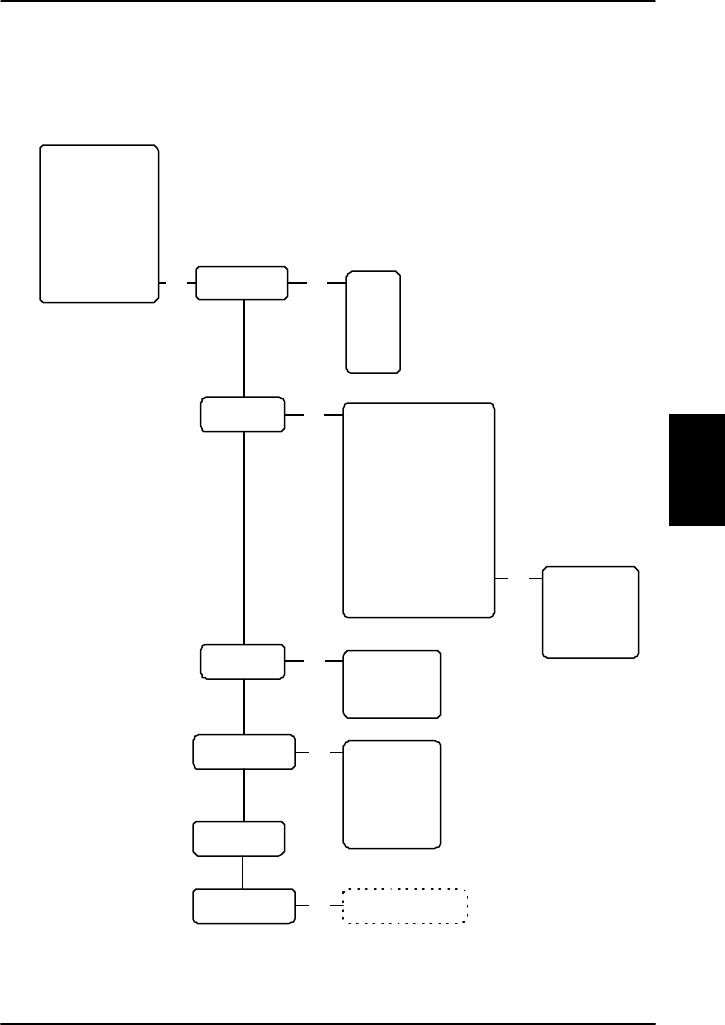
• Main software
• Handset 1 firmware
• Handset 2 firmware
• Handset 3 firmware
• Handset 4 firmware
Use B and E to scroll through the software.
LAN: Select LAN to view the status of the network.
Status can be “LAN link is up” or “LAN link is down”.
Active error: Select Active error to display information of
any active errors. If there is more than one error, use
B and E to scroll through the error list.

ISDN and MPDS Overview PC Connection
Dec 2003 89
5
5. PC Connection
5.1. ISDN and MPDS Overview
Please note: ISDN and MPDS services are only
available on Aero-HSD+ systems when the aircraft is
positioned inside an area with Spot Beam coverage.
Mobile Packet Data Service (MPDS) and Integrated
Services Digital Network (ISDN) are both services that
enable the mobile user to connect to the Internet. The
maximum data transfer rate is 64 kbit/s.
The difference between the Mobile ISDN and MPDS is
that with Mobile ISDN you are charged for connection
time and with MPDS you are charged for Mbits
transferred. This means that for applications like Web
browsing, email services, IP/LAN connectivity and small to
medium size file transfer, the MPDS will be the most
economic and convenient solution.
While in MPDS or ISDN mode the terminal is flagged busy
in the Inmarsat network, i.e. it is not able to receive any
ISDN calls, until it returns to normal idle mode.
For information on how to set up the computer and
transceiver for an MPDS connection, see section 5.2.2
Setting up MPDS via Ethernet and PPPoE.
For information on how to set up the computer and
transceiver for an ISDN connection, see section 5.2.3
Setting up ISDN.
PC Connection Setup of Data Equipment
90 Dec 2003
5
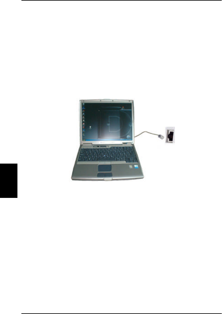
5.2. Setup of Data Equipment
5.2.1. Hardware connection
The illustrations below show typical hardware setups for
MPDS and ISDN data connections.
MPDS Ethernet Hardware Connection.
For an MPDS over Ethernet session, connect a LAN cable
between the Ethernet port of the computer and the
Ethernet port on the Aero-HSD+ system.
RJ-45
Connector
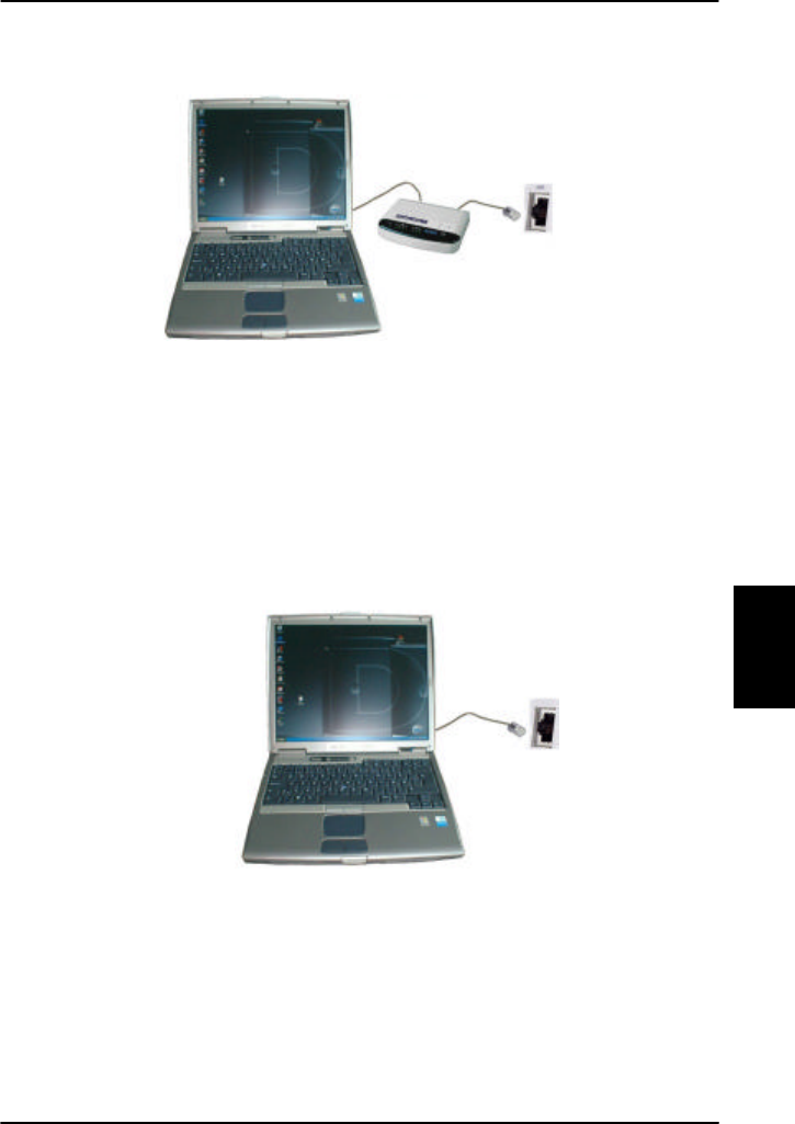
Setup of Data Equipment PC Connection
Dec 2003 91
5
ISDN Hardware Connection.
The ISDN connection is made by connecting an ISDN
modem (or Terminal Adapter) to the computer. See the
manufacturer’s installation guide for details on how to do
this. Connect the modem to the Aero-HSD+ system via an
ISDN cable. The appropriate modem driver must be
installed on the computer. See the manufacturer’s
installation guide for details on how to do this.
ISDN / MPDS Hardware Connection through Router
For an ISDN/MPDS connection through a router, connect
a LAN cable between the Ethernet port of the computer
and an Ethernet port on the router. Follow the setup
guide from the router supplier.
RJ-45
Connector
RJ-45
Connector

PC Connection Setup of Data Equipment
92 Dec 2003
5
5.2.2. Setting up MPDS via Ethernet and
PPPoE
This chapter describes the set-up and operation of MPDS
connections via Ethernet and PPPoE using various PPPoE
clients.
Windows XP with built-in PPPoE client
Prerequisites
The PC must have an Ethernet adapter and Windows XP
installed and both must be operational. There must be a
network connection between the PC and the Aero HSD+
system.
Setting up the Connection
1. From the “Start” menu select “Settings” then
“Network Connections” and then “Create New
Connection”.
This brings up the “New Connection Wizard”.
2. Click “Next”.
3. Select “Connect to the Internet” and click “Next”.
4. Select “Setup my connection manually” and click
“Next”.
5. Select “Connect using broadband connection
requiring user name and password” and click “Next”.
6. Type a name for the connection, e.g. ”MPDS via
PPPoE” and click “Next”.
7. Select “Anyone” and click “Next”.

Setup of Data Equipment PC Connection
Dec 2003 93
5
8. Type a random user name and password and click
“Next”.
9. Select the shortcut on desktop option.
10. Click “Finish”.
11. Now click the new shortcut on the desktop named
“MPDS via PPPoE”. The Aero-HSD+ system should
now connect to MPDS.
Note:
Because of the relatively long set-up time for an MPDS
connection, the PPPoE connection may some times time
out.
Windows 2000 and WinPoET™ PPPoE
client
(Tested under MS Windows 2000)
The MPDS connection via Ethernet and PPPoE can be
established using various PPPoE clients. For this example
WinPoET client was used.
Prerequisites
The computer must have a working Ethernet adapter.
Windows Dial-Up Networking (DUN) must be installed.
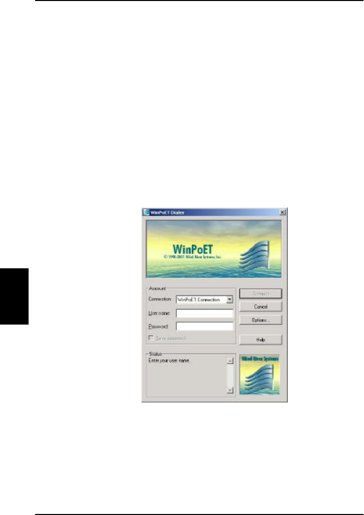
PC Connection Setup of Data Equipment
94 Dec 2003
5
Installation
The WinPoET program is contained in a self extracting
zip-file.
1. Double click the icon, and installation begins.
2. Click ‘OK’ and ‘Next’ a few times to accept license
agreement and accept rebooting the computer (only
older windows versions.)
3. To make the first connection with WinPoET, click the
start button, and find the new program folder
‘iVasion’.
4. In ‘iVasion’, press ‘WinPoET‘ and ‘WinPoET dialer’.
5. Enter random user name and password, and click
connect.

Setup of Data Equipment PC Connection
Dec 2003 95
5
The status field tells you how far you have reached in the
connection process.
The phases of a successful connection are:
• Click Connect to start the connection process.
• Connecting to communications device.
• Starting authentication process.
• Starting projection phase.
• Authentication completed successfully
• Connected
After the first connection, WinPoET creates a ‘WinPoET
Connection’ in the ‘Network and dial-up connections’
folder that can be used with the standard Windows DUN
system (Automatic dialling and disconnection etc.).
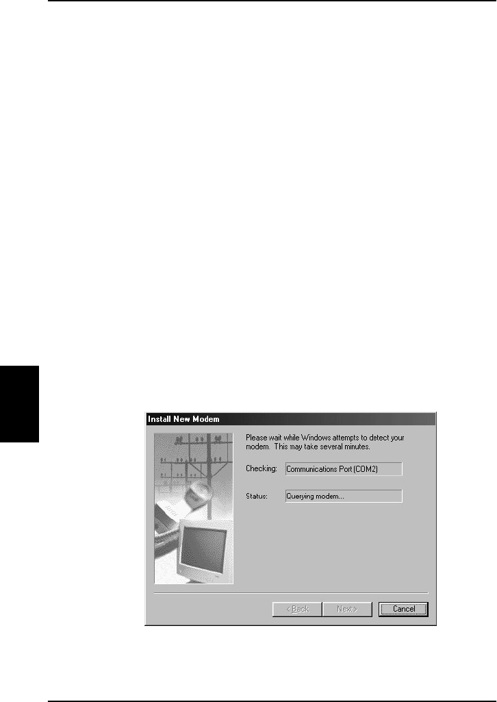
PC Connection Setup of Data Equipment
96 Dec 2003
5
5.2.3. Setting up ISDN
The Aero-HSD+ transceiver is connected to ISDN
equipment via an ISDN cable.
The example below shows how to setup an Internet
connection via ISDN.
1. Connect an ISDN modem to the ISDN interface.
2. Connect the modem to a PC, via a PCMCIA Card.
3. Follow the modem manufacturer’s installation
instructions for the appropriate operating system.
For the following example, a Lasat Unique 1280i ISDN
modem was installed under Windows 98.
Step 1: Install a modem
1. From the Control Panel select Modems and add a
modem.
2. Let Windows detect the modem automatically.
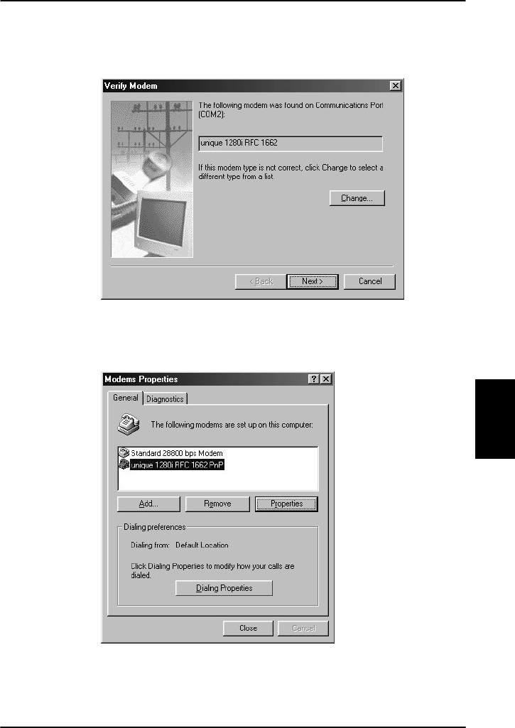
Setup of Data Equipment PC Connection
Dec 2003 97
5
When the modem is detected, the following window
appears.
3. Verify that the modem is installed.
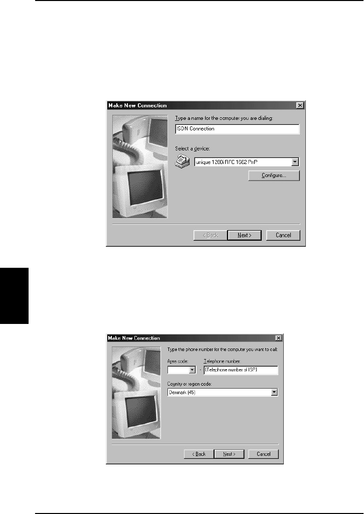
PC Connection Setup of Data Equipment
98 Dec 2003
5
Step 2: Create a Dial-up connection
1. Open Dial-up Networking from My computer and click
“Make new connection”.
2. Give the connection a recognizable name e.g. ISDN
Connection.
3. Select the Lasat modem defined during step 1 as the
dial up device.
4. Enter the telephone number to the Internet Service
Provider. Remember country code and area code if
necessary.
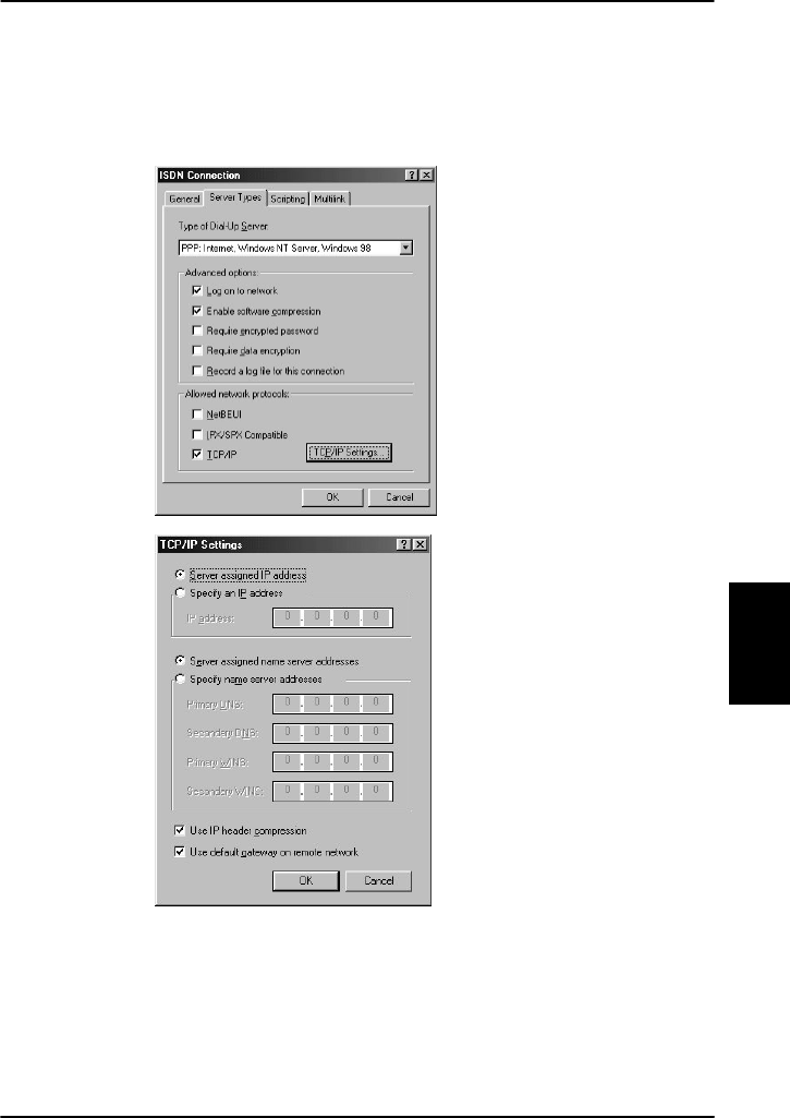
Setup of Data Equipment PC Connection
Dec 2003 99
5
5. Include TCP/IP as allowed network protocol and use
TCP/IP settings (Server assigned IP address, Server
assigned name server addresses etc.) as
recommended by the ISP.
After this, the connection can be made as described in
section 5.3.

PC Connection Setup of Data Equipment
100 Dec 2003
5
5.2.4. Setting up a Router
For information on how to set up a router, see Chapter 3
in the manual “AeroROUTER 700” PN# 500420.
5.2.5. Setting up a H+ Modem Connection
With the Aero-HSD+ modem connection, you can use any
application supporting modem speeds at 2400 bps and a
satellite delay of 200 ms.
Do as follows to set up the modem:
1. Connect the modem to the Satcom (Satcom
connection #5 or #6).
2. On the desktop, double click "My computer".
3. Double-click "Dial-up networking".
4. Double-click "Make new connection".
5. Type a name for the connection (e.g. "2400 BPS via
AERO-HSD+").
6. Select the modem to use.
7. Click Next.
For an outgoing call, in the phone number, the
international prefix “00” must be replaced by “02”, to
indicate a modem data call.
8. Click Next.
9. Click Finish.

Setup of Data Equipment PC Connection
Dec 2003 101
5
Advanced settings for the modem connection:
Type the AT command relevant for your modem to set the
corresponding parameters in Extra settings window:
• Communication protocol: V22bis and V42bis
• Error correction: LAPM
• Guard tone: OFF (if possible)
NOTE: AT commands can be pre-programmed in nearly
all modems. Contact your modem manufacturer for
further information.
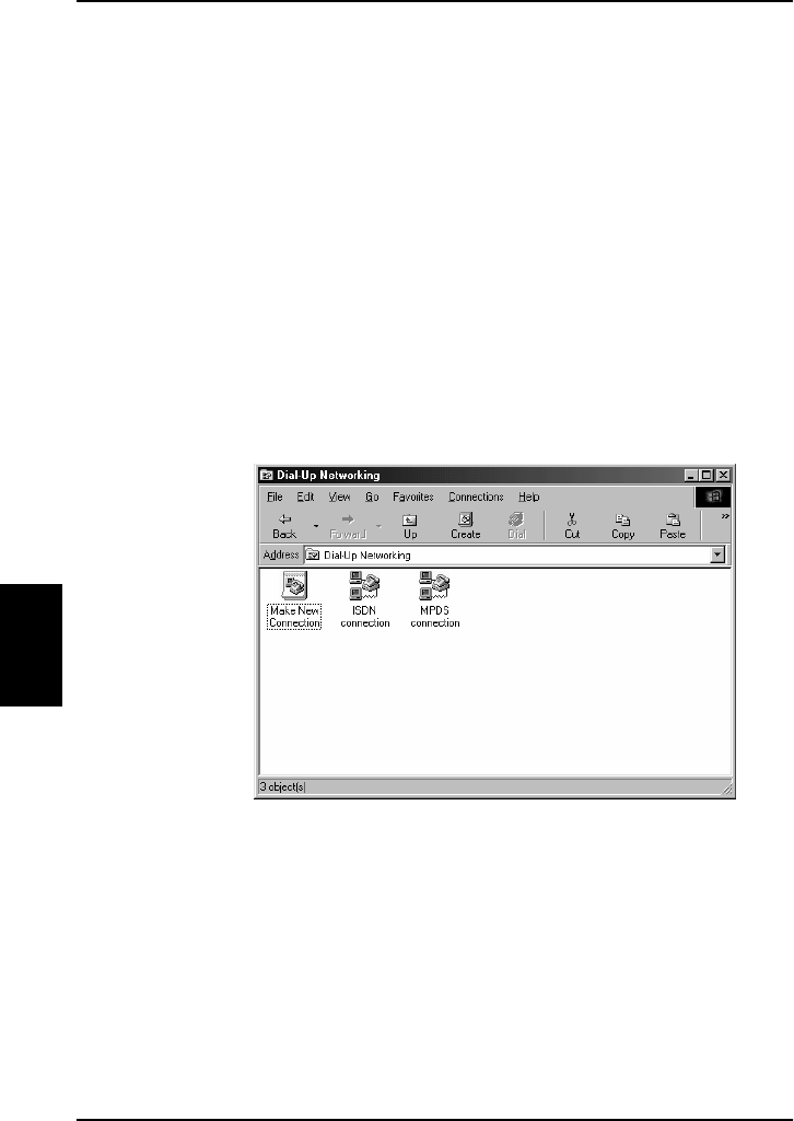
PC Connection Connecting to the Network
102 Dec 2003
5
5.3. Connecting to the Network
A connection can be started automatically by an
application like Internet Explorer or Outlook Express. The
connection can also be established manually.
To establish the connection manually, do as follows:
1. In windows, open Dial-Up networking and double
click the appropriate icon.
2. Enter username and password if necessary.
3. Click ‘Connect’.
Wait for the connection to be completed, indicated
by a ‘Dial-up Networking’ icon in the task bar tray.
The connection can be disconnected by right-clicking the
tray icon and choosing ‘Disconnect’.

Overview Troubleshooting
Dec 2003 103
6
6. Troubleshooting
6.1. Overview
If case of a fault situation, first check that the H+ and/or
HSD LEDs are lit, and that the display reads “Ready”.
Also make sure that the transmission path is not
obstructed, e.g. by buildings if the aircraft is on the
ground.
The system is able to display various error codes to help
you troubleshoot the system. The following sections
provide an overview and a list of some of the error codes
you may see in the display.
If you need further assistance, please call the supplier of
the Aero-HSD+ System.

Troubleshooting
104 Dec 2003
6
6.2. Error codes
If there is a fault, the type of fault and the fault code is
displayed in the Full Feature Handset. Where possible
the fault code is translated into plain text. Two types of
fault codes are defined:
• BITE errors
• Cause Codes
For a complete list of BITE error codes and Cause Codes,
please refer to the Installation and Maintenance Manual.
6.2.1. BITE Errors
A BITE error is a hardware error detected by the
automatic error detection system in the Aero-HSD+
system.
The red LED on the handset indicates the presence of a
fatal or essential BITE error.
A fatal BITE error means that you are logged off and
cannot log on again.
An essential BITE error means that the functions are
limited and one or more services are not available.
A non-essential BITE error means that there are minor
errors, but all services are still available. The red LED on
the handset will not indicate this type of error.
Please report any BITE errors to the Maintenance
Responsible.
When a BITE error is present, the display toggles
between the error code and the previous display
contents.
The BITE error is shown in the second line of the display.
A BITE error has a unique 4-characters BITE code.

Error codes Troubleshooting
Dec 2003 105
6
You can also view any active BITE errors in the Status
menu under Active Error.
6.2.2. Cause Codes
A Cause Code describes a fault detected by the Earth
Station during a call.
The cause codes can help you find the reason for an
error. In most cases, errors are caused by a problem in
the satellite network.
The Cause Code is displayed in the handset for a few
seconds after the call is interrupted. If possible, the code
is translated into plain text instead of the Cause Code. A
Cause Code is a unique 4-characters code.
The following section shows a list of cause codes with an
explanation of the error message.
Troubleshooting
106 Dec 2003
6
6.3. List of Cause Codes
Note: Cause Codes should not be mistaken for BITE
error codes. See the previous page for an explanation of
the two kinds of error codes.
6.3.1. Logon Cause Codes
The following list shows the cause codes that may
appear during logon.
Display text
Description Guidance
ClassReject Class rejected The GES proposes that the
class is not supported
GlobChanLoss
Global channel
loss
GlobCunavlb Global C channel
not available at
GES
ManualLogRej
Manuel login
rejected
Manual logon is not allowed
when logon policy is
automatic
NetworkFail Network Failure
NoGesSignal No GES signal
NoInitData No valid system
table available
NoSatSignal No satellite signal
Verify that there are no
obstacles between the
satellite and the AES antenna
List of Cause Codes Troubleshooting
Dec 2003 107
6
Display text
Description Guidance
NotAuthorizd AES not
authorized Verify that the ICAO address
used is correct. I
f it is, contact
the service provider to verify
that the ICAO address is
registered.
OtherReason Other Reason
OutsideCover
Outside spot
beam coverage
The AES is not under a spot
beam of the specified GES
P/R/Tunavlb Packet data
channel
unavailable
PkdtaUnavlb Packet data
service
unavailable
SDUfailure SDU failure Check the current bite errors
SpotChanLoss
Spot channel loss
TableFull Table Full
UserLogoff User logoff
VCC&dUnavlb
Voice not
available at GES
VoiceUnavlb Voice Unavailable
WrongGES GES not existing Check GES ID validity
WrongGESid Wrong GES
identifier
Check GES ID validity
WrongParam Wrong Parameter
WrongSatID Wrong Satellite
identifier
Check satellite ID validity
Troubleshooting
108 Dec 2003
6
6.3.2. Cause Codes after Logon
The following list shows some of the cause codes that
may appear when the system is logged on.
Display text Inmarsat description
Normal clearing
AddrComplete Address complete
AESabsent AES absent
AnalogFail Analogue data equipment is not
available
AnalogRate Required analogue data rate is not
supported
Busy User busy
CallBared Incoming calls are barred
CallPreempt Call is pre-empted
CallRejected Call is rejected
CardInvalid Credit card type is not supported
CardRejected Credit card number is rejected
ChanAbsent Channel type is not implemented
ContFailure Continuity failure
DigitalFail Digital data equipment is not
available
DigitalRate Required digital data rate is not
supported
GndDestFail Destination out of service
Handover Spot beam handover
List of Cause Codes Troubleshooting
Dec 2003 109
6
Display text Inmarsat description
InvalidAddr Invalid/incomplete address
InvalidNumbr Invalid number format
NetworkFail Network is out of order
NoAnswer No user is responding
NoChanAvail No channel is available
NoCircuit No circuit/channel is available
NoRoute No route to destination
NoUnitAvail No channel unit is available
SatDestFail Destination out of service
ServiceType Service type is not supported
SwitchBusy Switching equipment congestion
UnassignedNo Unassigned number
Unauthorized AES not authorised
Undefined Undefined cause
Unspecified Normal, unspecified
User Busy User is busy
VoiceTypeErr Voice channel type is not supported
WrongNumber Unassigned number

Troubleshooting
110 Dec 2003
6
This page is intentionally left blank

Appendix A - Menu Tree
Dec 2003 111
A
Appendix A - Menu Tree
The next page shows an overview of the complete menu
tree. For details on each menu, refer to the section The
Menus on page 58.
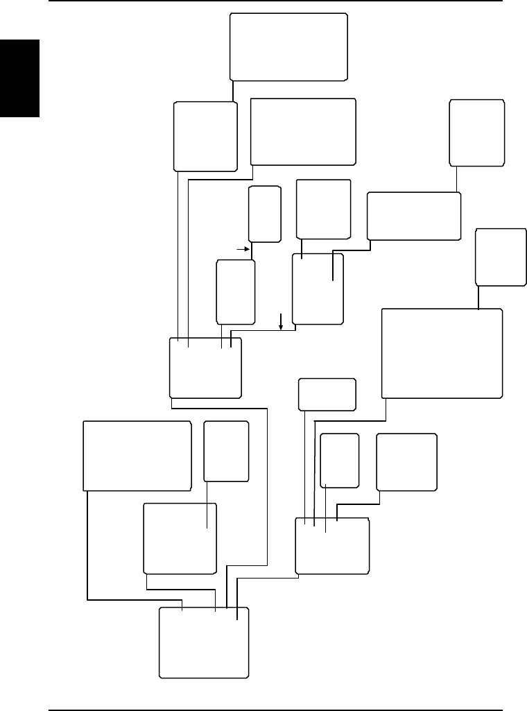
Appendix A - Menu Tree
112 Dec 2003
A
RingProfiles
QuickDial
Disclose Pos
Fax Setup
Pin Setup
Configure
Silent
Contrast
Light
Key Beep
Single Ring
Common Ring
Ring Volume
Phone Volume
ComfortNoise
Phone Book
HandsetSetup
Ring Profile
Lock System
Logon Menu
System Setup
Status
Manual Logon
Custom Logon
Auto Logon
Renew Logon
Logoff
Settings Logon Policy
H+ GES
ISDN LES
MPDS LES
1 <empty>
2 <empty>
3 <empty>
4 <empty>
TakeOfLandng
Handset #1
Handset #2
Handset #3
Handset #4
POTS #1
POTS #2
ISDN
Annunciator1
Annunciator2
Annunciator3
1 <empty>
2 <empty>
3 <empty>
4 <empty>
5 <empty>
6 <empty>
7 <empty>
8 <empty>
9 <empty>
Change Pin
Disable Pin
Enter
Pin Code
Handset Type
Known GESs
Known LESs
Init Sat
Sat #1
Sat #2
Sat #3
Sat #4
Spare #1
Spare #2
Spare #3
Spare #4
Handset #1
Handset #2
Handset #3
Handset #4
Satellite Id
Longitude
P-Channel #1
P-Channel #2
Service Provider
Pin Code
Channels
Nav Data
SDU
SW Version
LAN
Active Error
Latitude
Longitude
Altitude
Speed
Nav Source
IRS Active
AHRS Active
GPS Active
Show Detailed Nav
Show Antenna Pos
PRT
C1
C2
HSD
Heading
Pitch
Roll
Doppler Vel
Serial No.
ISN
ICAO
Main
Handset 1
Handset 2
Handset 3
Handset 4
NormalUsrPin
SuperUserPin
ServPrvdrPin
Menu Tree

Glossary
Dec 2003 113
Glossary
ACARS Aircraft Communication Addressing & Reporting
System
AFIS Automatic Flight Information Service
AHRS Attitude and Heading Reference System
AORE Atlantic Ocean Region East
AORW Atlantic Ocean Region West
ATM Air Traffic Management
baud Modulation speed in a modem (baud ≤ bit/s)
bit binary digit
bit/s bits per second (baud ≤ bit/s)
BITE Build In Test Equipment
C-channel A channel which provides a bidirectional
communications channel between ground and
air. C-channels are typically used for voice
communications.
CM Configuration Module
CMU Communications Management Unit
CNS Communication Navigation Surveillance

Glossary
114 Dec 2003
COM Contraction Of Communication
DUN Dial Up Network
FAX Facsimile And Telefax
FMS Flight Management System
GES Ground Earth Station
GPS Global Positioning System
H+ An Inmarsat aeronautic data and voice service
HGA High Gain Antenna
HPA High Power Amplifier
HSD High Speed Data
HSU High Speed Unit
ICAO International Civil Aviation Organization
ID Identification
IDD International Direct Dialling
IMN Inmarsat Mobile Number
Inmarsat International Maritime Satellite Organisation
IOR Indian Ocean Region
IP Internet Protocol

Glossary
Dec 2003 115
IRS Inertial Reference System
ISDN Integrated Services Digital Network
ISN Inmarsat Serial Number
ISP Inmarsat Service Provider
LAN Local Area Network
LCD Liquid Crystal Display
LED Light Emitting Diode
LES Land Earth Station
MES Mobile Earth Station
Modem Modulate Demodulate
MPDS Mobile Packet Data Service
MSN Multiple Subscriber Number
NCS Network Co-ordination Station
PC Personal Computer
P-channel A channel which provides a uni-directional
dedicated communications channel from a
Ground Earth Station (GES) to all aircrafts. Data
packets are broadcast over this channel and
addressed to a specific aircraft.
PIN Personal Identification Number

Glossary
116 Dec 2003
POR Pacific Ocean Region
POTS Plain Old Telephony System
PPPoE Point-to-Point Protocol over Ethernet
PRT The total system communications channel
including the P-channel, R-channel and T-
channel
R-channel A channel which provides a uni-directional
dedicated communications channel from aircraft
to a GES. Access to this channel is contention
mode, with the timing signal (for the
transmission slots) being provided by the P-
Channel.
RF Radio Frequency
SCPC Single Carrier per Channel
SDM System Definition Manual
SDU Satellite Data Unit
SLCV Field in the Cause codes
(Standard/Location/Class/Value)
STE Secure Telephone Equipment
STU Secure Telephone Unit
SW Software

Glossary
Dec 2003 117
Swift64 An Inmarsat aeronautic High Speed Data
service
TA Terminal Adapter
T-channel A channel which provides a uni-directional
dedicated communications channel from aircraft
to a GES. T-Channels are used to convey
longer messages without the risk of conflict
that arises on the R-Channel. T-Channels are
allocated by a GES following a request received
over the R-Channel.
TCP/IP Transmission Control Protocol/Internet Protocol
TNID Terrestrial Network ID
UDI Unrestricted Digital Information
USB Universal Serial Bus
WAN Wide Area Network
Webcam Web Camera
WLAN Wireless Local Area Network

Glossary
118 Dec 2003
This page is intentionally left blank

Index
Dec 2003 119
Index
2nd functions....................... 28
3.1 kHz audio ............... 12, 14
56 kbit/s ............................. 12
DATA................................ 14
64 kbit/s ....................... 12, 89
UDI.................................. 14
Abbreviations ................... 113
Active error......................... 88
AHRS active ........................ 86
Alpha mode ........................ 30
Alpha-Numeric buttons....... 29
Altitude............................... 86
Antenna position................ 87
Auxiliary Cradle .................. 20
Auxiliary Handset ............... 20
BITE error codes............... 104
Booting............................... 37
Call
Conference...................... 47
From 2.4 GHz Cordless
phone........................... 54
From auxiliary handset.... 48
From Full Feature handset43
From phone book............ 44
From POTS handset......... 48
From Sigma7 phone ......... 53
Internal........................... 45
Quick dial......................... 44
To the terminal................ 57
Using ISDN ...................... 55
Call transfer
Auxiliary handset............. 52
Full Feature handset....... 46
Caps toggle ........................29
Cause codes.....................105
List of.............................106
CDM ....................................17
Change pin code.................79
Channels
signal strength ................86
ComfortNoise......................64
Commission ........................13
Components of Aero-HSD+.17
Conference call ...................47
Configuration......................80
Contrast .............................62
Data....................................12
Detailed navigation.............87
Dial-Up networking ...........102
Disable pin code .................79
Disclose position.................75
Display symbols ..................24
Documentation
Related ..............................9
Doppler velocity ..................87
Email...................................89
Error
View active ......................88
Error codes .......................104
BITE ...............................104
Cause codes..................105
List of.............................106
Fault
View active ......................88
Fax......................................12
3.1 kHz audio...................56

Index
120 Dec 2003
H+ ...................................55
HSD .................................56
ISDN ................................56
Fax setup ...........................75
Features of Aero-HSD+.......16
File transfer........................89
Full Feature Cradle .............20
Full Feature Handset....20, 21
Function buttons ................25
Geo-stationary ...................11
GES.....................................12
List of known...................82
List of preferred...............70
Glossary ...........................113
GPS active ..........................86
H+ ......................................11
Handset type......................82
HandsetSetup ....................60
Heading..............................87
HPA.....................................19
ICAO address .....................87
Inmarsat.............................11
Internal calls.......................45
International access codes.57
Internet Explorer..............102
IP/LAN ................................89
IRS active ...........................86
ISDN ...................................89
Hardware setup ..............91
Phone call........................55
Setup of connection.........96
ISN .....................................87
Key beep............................63
Lattitude.............................86
LCD.....................................22
LEDs ...................................23
LES.....................................12
List of known .................. 83
List of preferred, ISDN .... 71
List of preferred, MPDS ... 72
Light in handset................. 62
Lock System....................... 65
Logoff................................. 67
Logon................................. 66
Automatic........................ 67
Custom ........................... 67
Manual............................ 67
Policy............................... 70
Renew............................. 67
Settings .......................... 68
Longitude........................... 86
Manuals
Other ................................ 9
Memory
Auxiliary handset ............ 49
Menu
Accessing ........................ 41
Entering selected............ 41
Exiting............................. 41
Overview....................... 111
Scrolling through............. 41
Shortcuts ........................ 41
Tree .............................. 111
Modem
H+ setup....................... 100
MPDS...................... 12, 14, 89
Hardware setup.............. 90
Setup using Ethernet and
PPPoE .......................... 92
Windows 2000 and PPPoE93
Windows XP and PPPoE.. 92
Navigation
Data ................................ 86
Show detailed................. 87

Index
Dec 2003 121
Source ............................. 86
NCS.................................... 11
Normal User ................. 39, 41
Outlook Express............... 102
Packet Data Channel.......... 14
Phone book........................ 58
Delete entry .................... 59
Dial from.......................... 59
Edit entry ........................ 59
Insert new entry ............. 59
Making a call.................... 44
Phone volume .................... 64
Pin codes
Changing......................... 79
Types .............................. 39
Pin setup............................ 79
Pitch ................................... 87
POTS phone ....................... 48
Prefix.................................. 43
Quick dial............................ 78
Delete entry .................... 78
Edit entry ........................ 78
Making a call.................... 44
Recalling a stored number
Auxiliary handset............. 51
Redial
Auxiliary handset............. 52
Full Feature handset....... 44
Ring profile
Defining........................... 76
Selecting ......................... 65
Ring tone
All handsets .................... 63
Broadcast call.................. 63
Current handset.............. 63
Direct call......................... 63
Ring volume ........................63
Ringmode
Defining ...........................76
Selecting..........................65
Roll......................................87
Router
Hardware setup...............91
Setup.............................100
Satellites.............................11
List of...............................83
SDU.....................................19
Serial number ..................87
Service Provider..................41
Services ..............................14
Signal strength ...................86
Silent function.....................62
Software version ................88
Applicable ..........................8
Special characters...............29
Speech..........................12, 14
Speed .................................86
Spot-beams ........................11
Status.................................84
Storing a phone number
Auxiliary handset.............49
Super User....................39, 41
SW version .........................88
Swift64 ...............................11
System components ...........17
System setup......................73
Transferring a call
Auxiliary handset.............52
Full Feature handset........46
Troubleshooting................103
Voice ...................................12
Web browsing ....................89