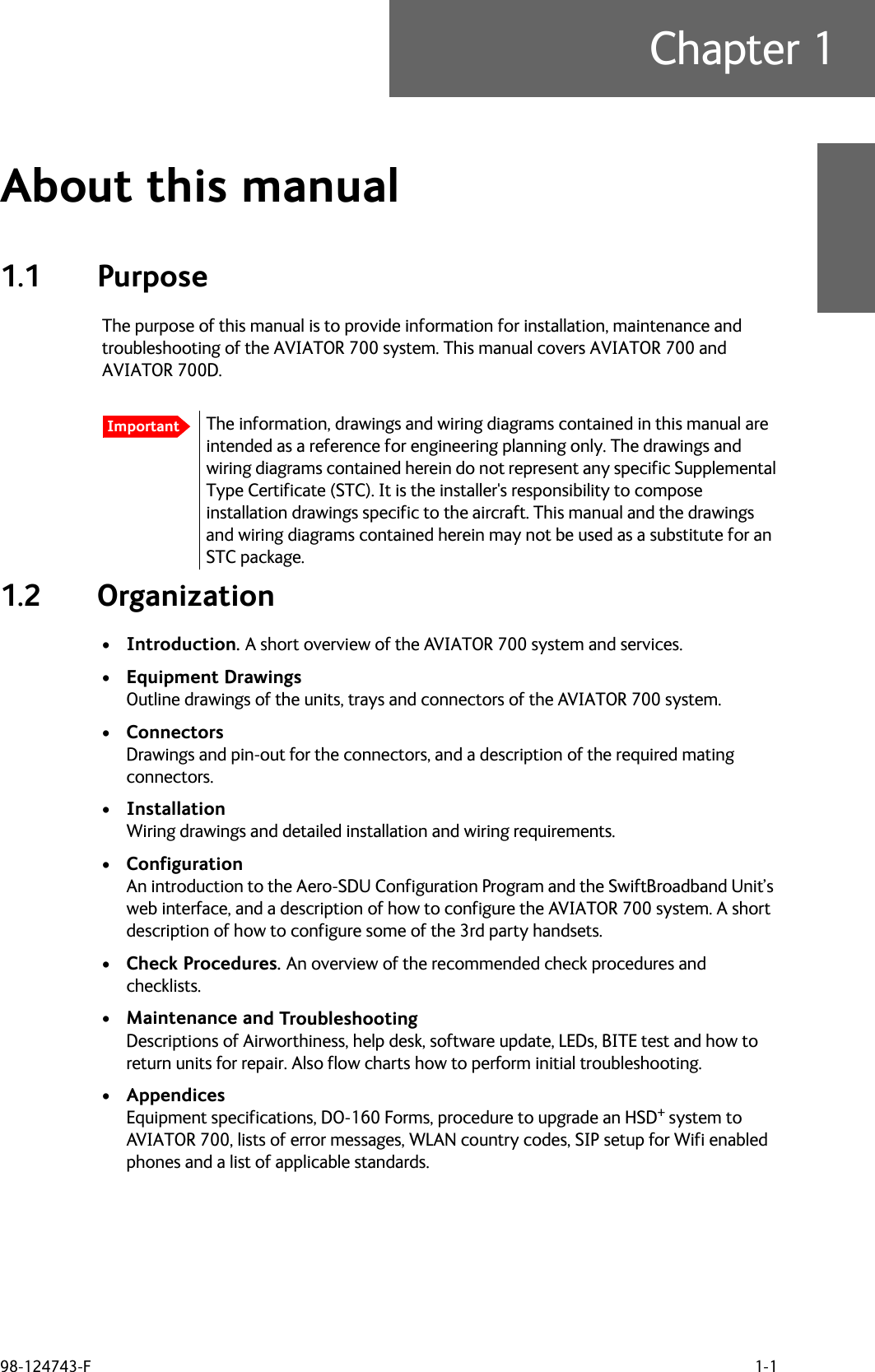
Thrane and Thrane A S AVIATOR700 Satellite transceiver for Inmarsat Swift Broadband service User Manual 98 124743
Thrane & Thrane A/S Satellite transceiver for Inmarsat Swift Broadband service 98 124743
Contents
- 1. Installation Manual
- 2. Users Manual
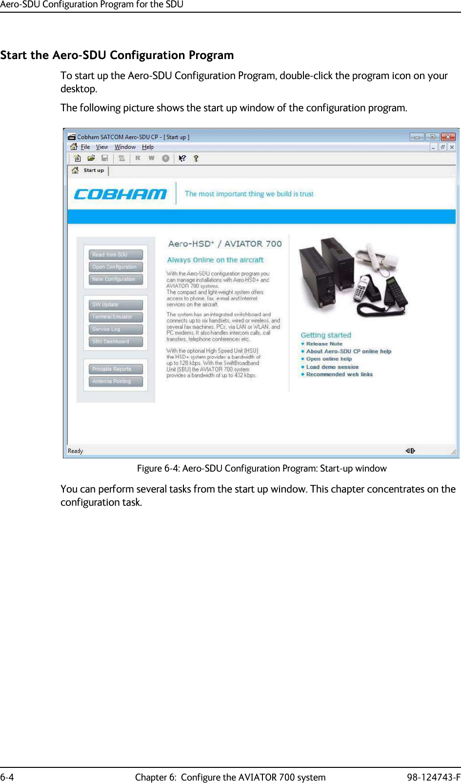
Installation Manual
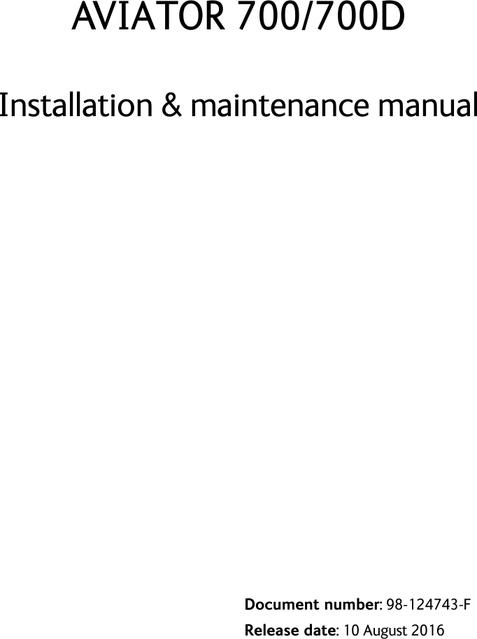
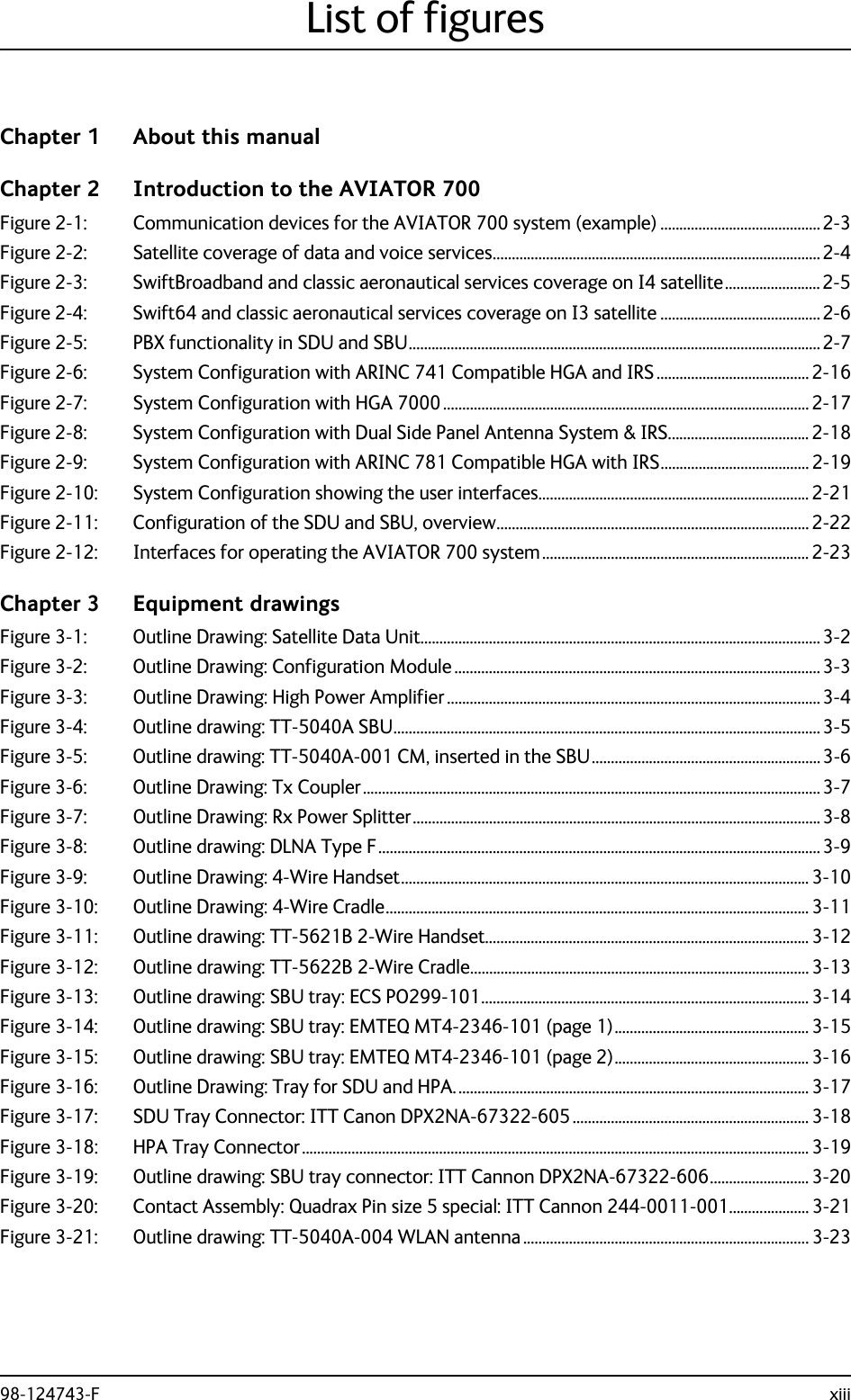

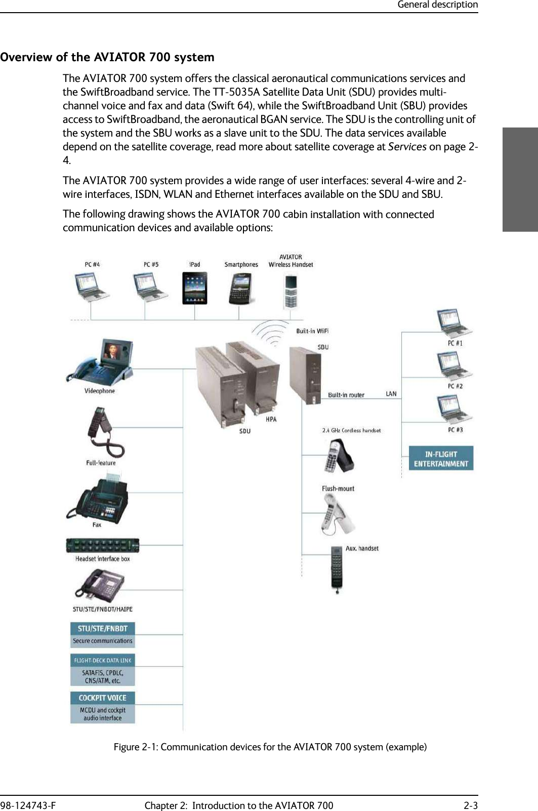
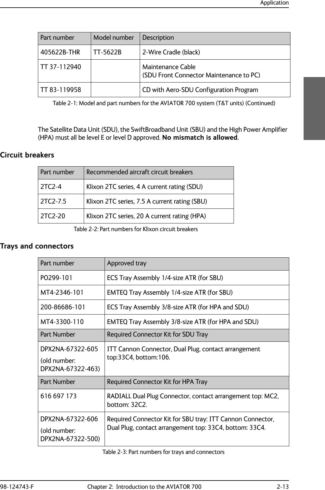
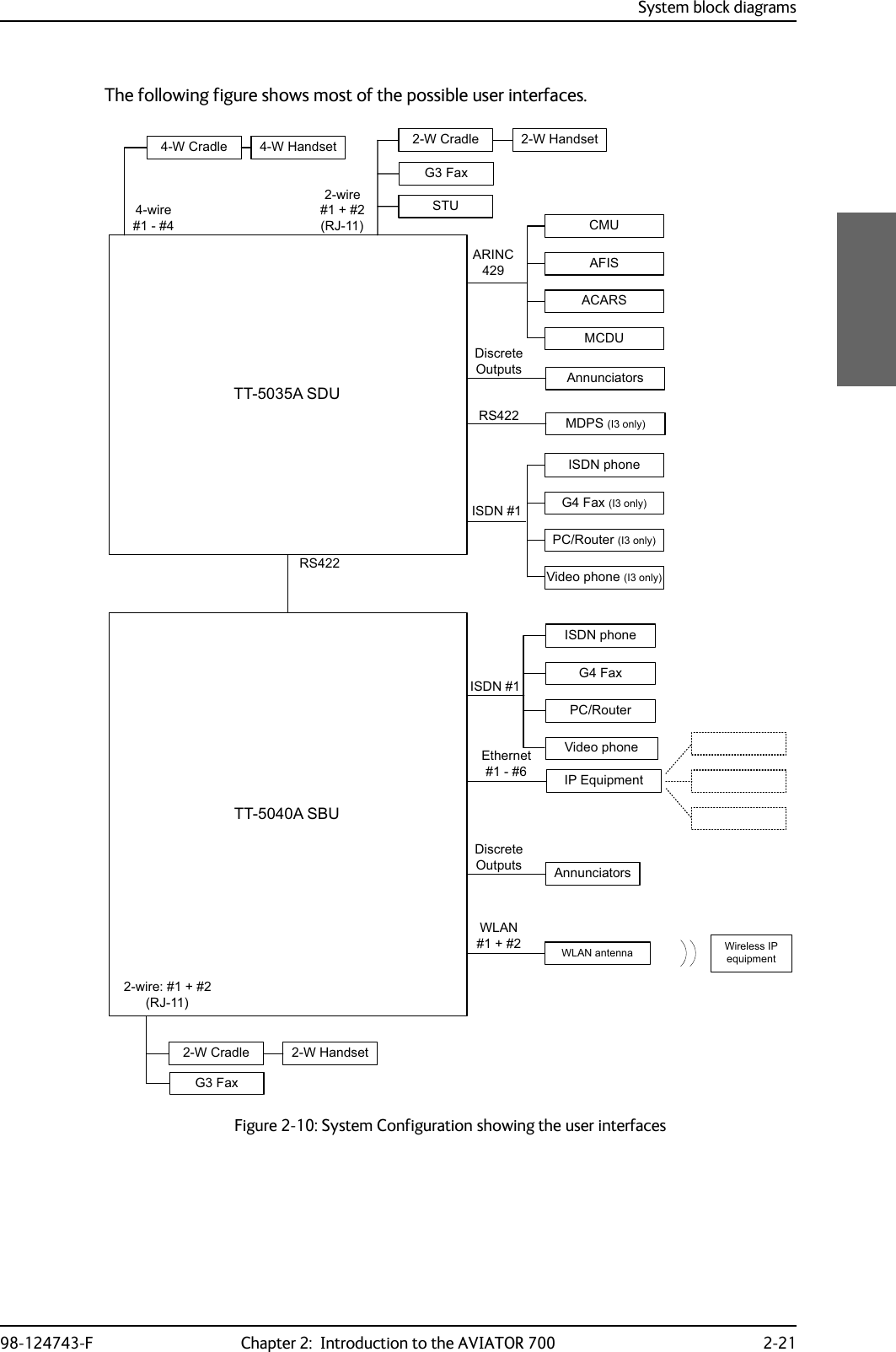
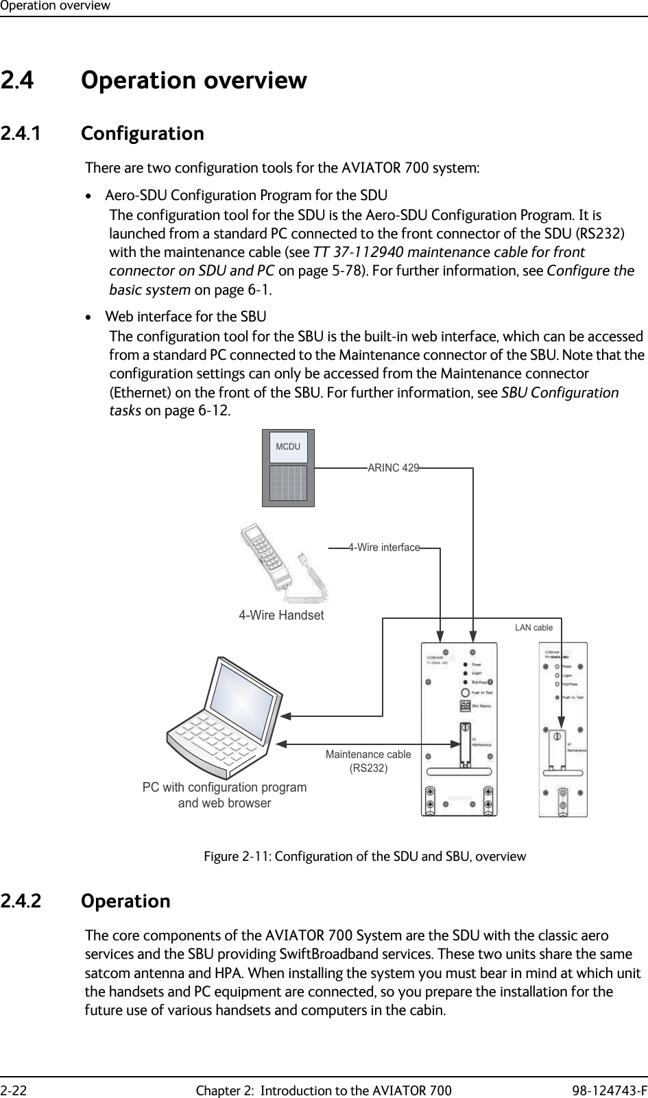
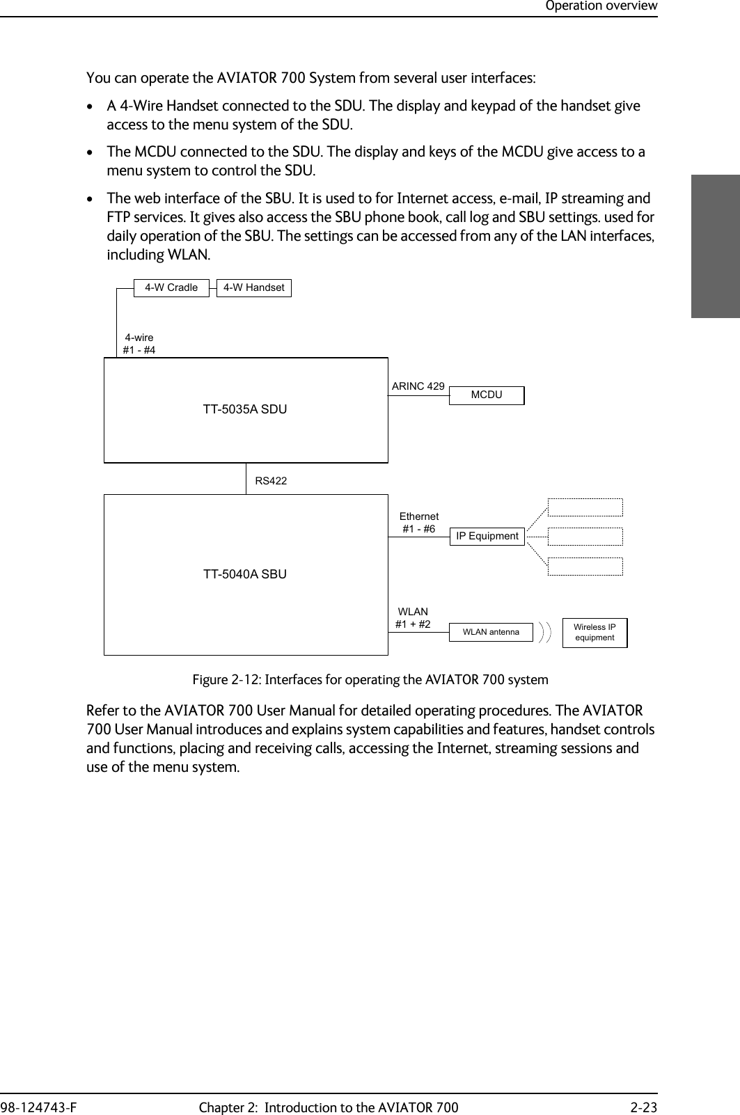
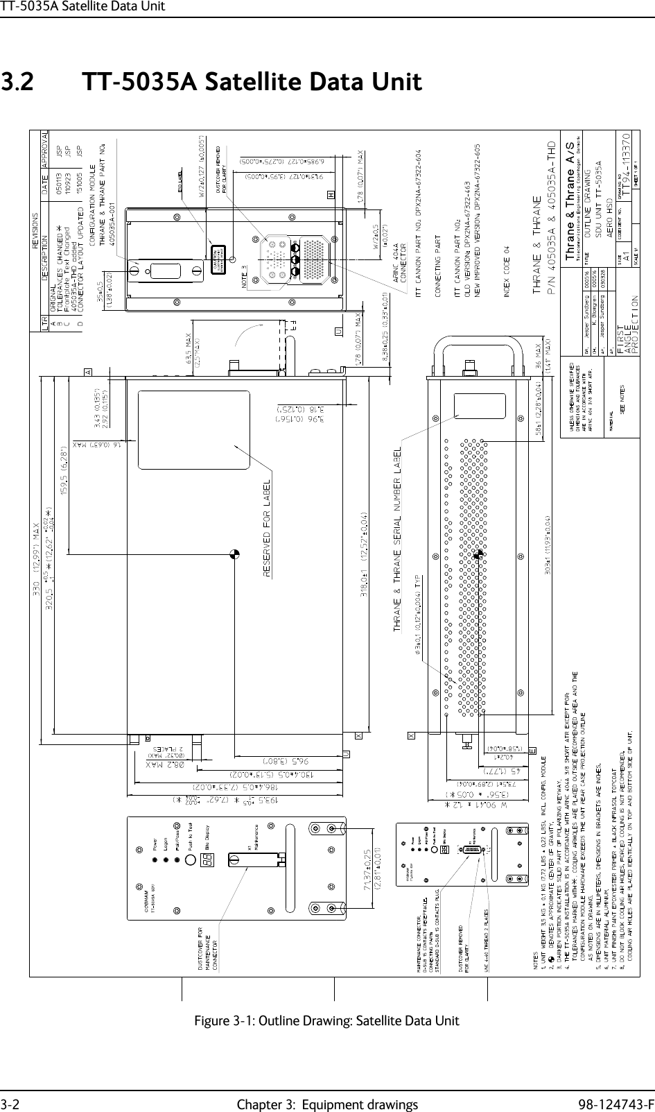
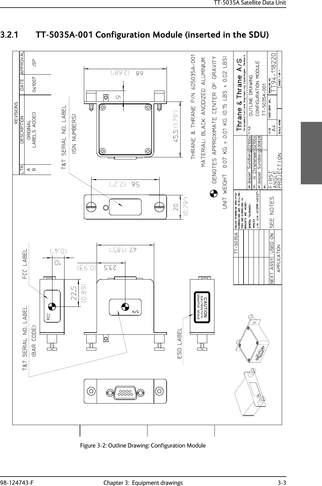
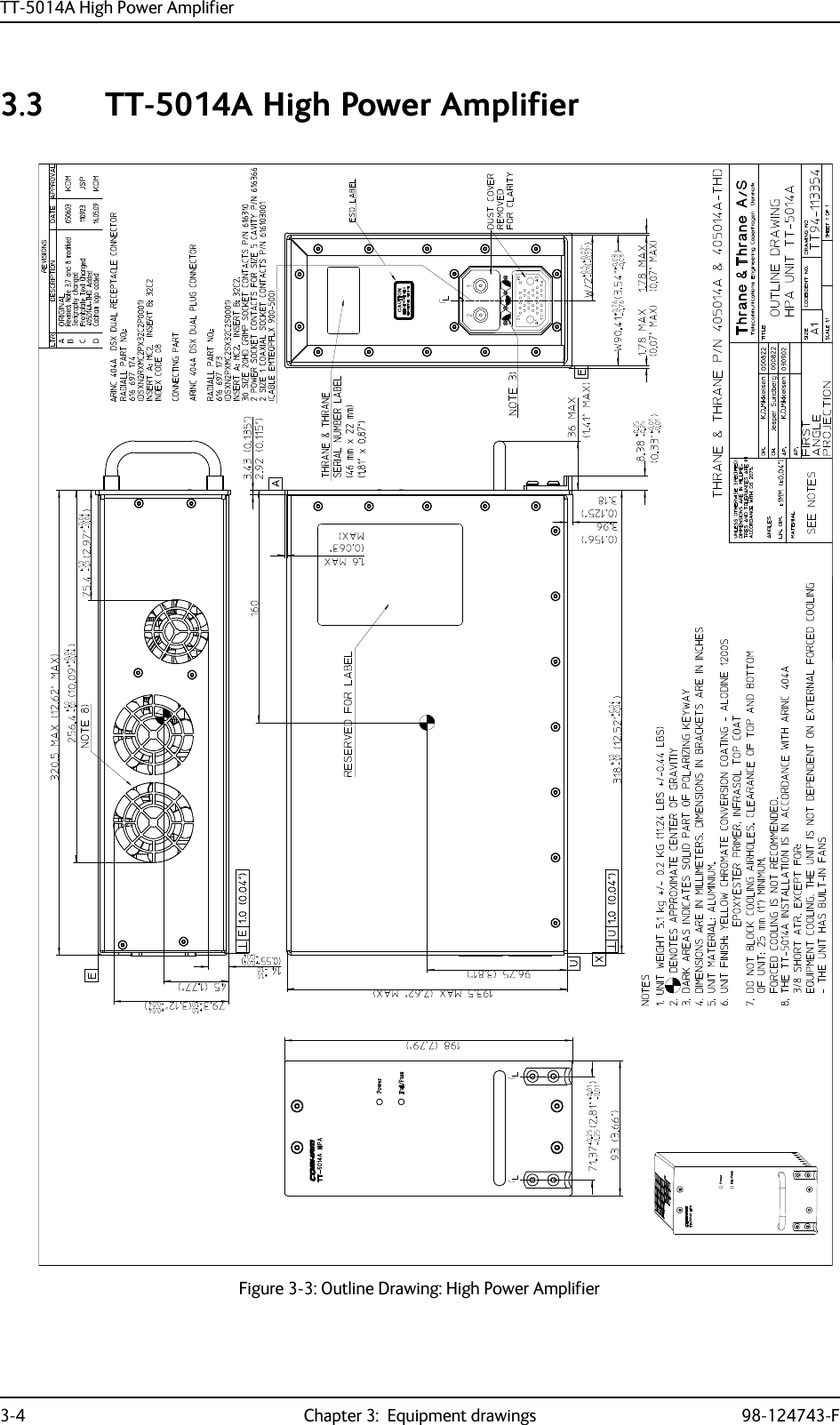
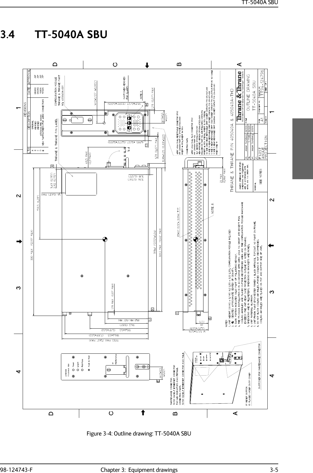
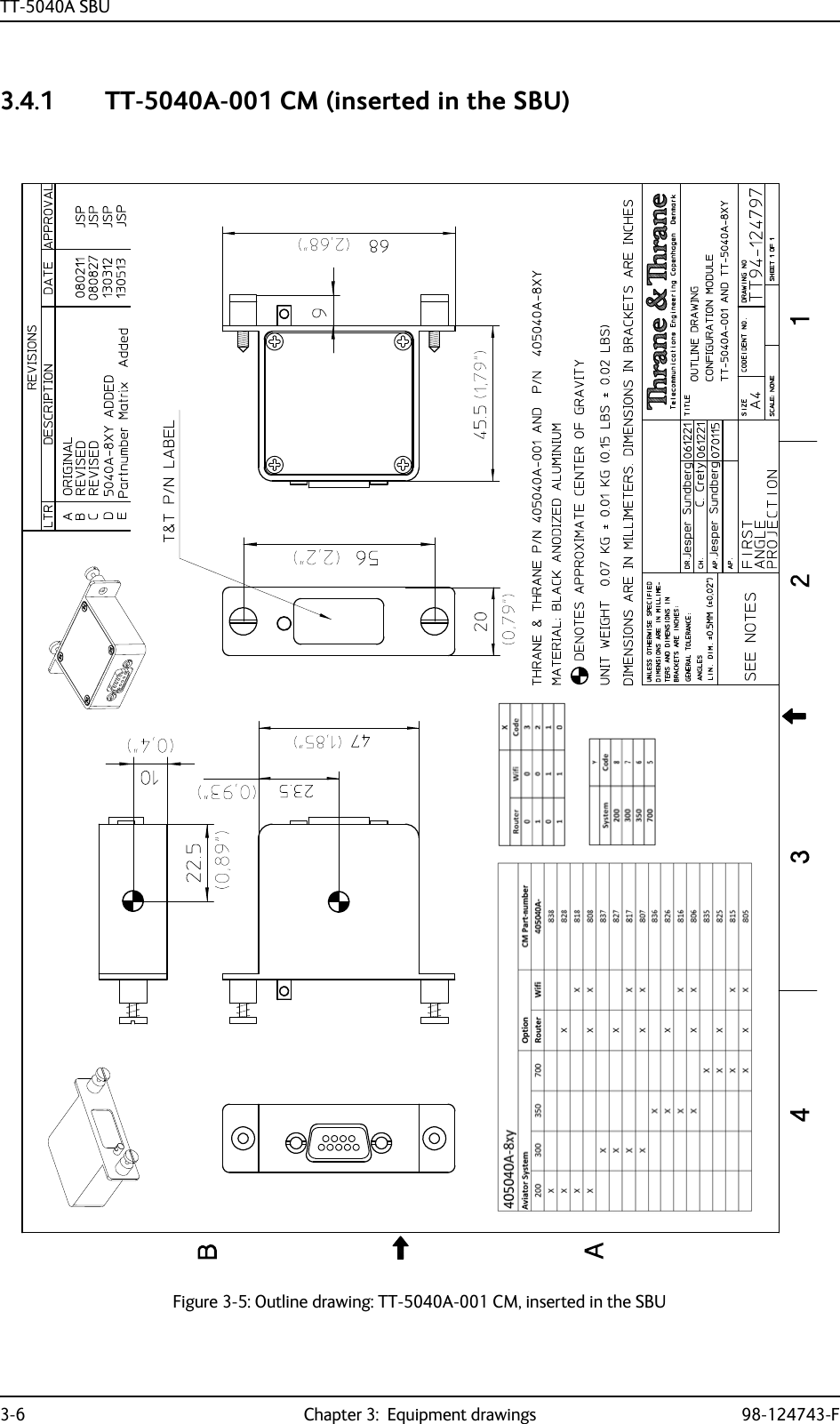
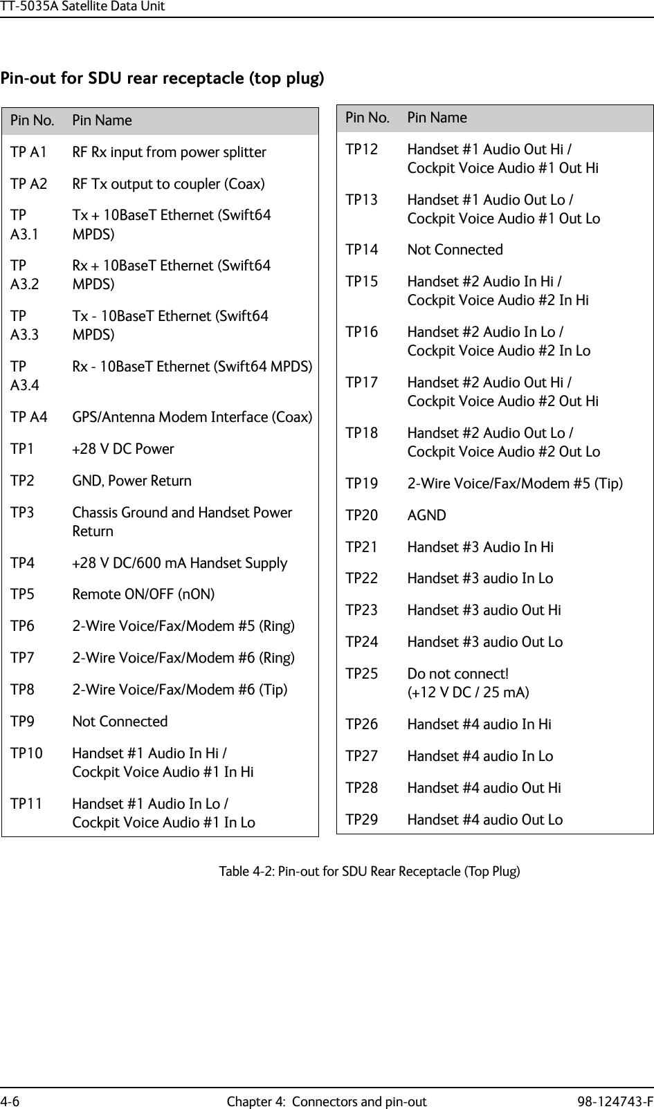
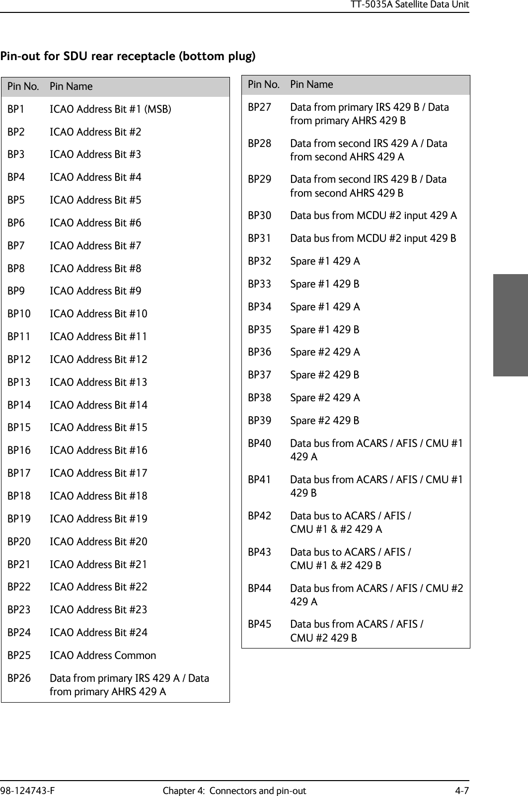
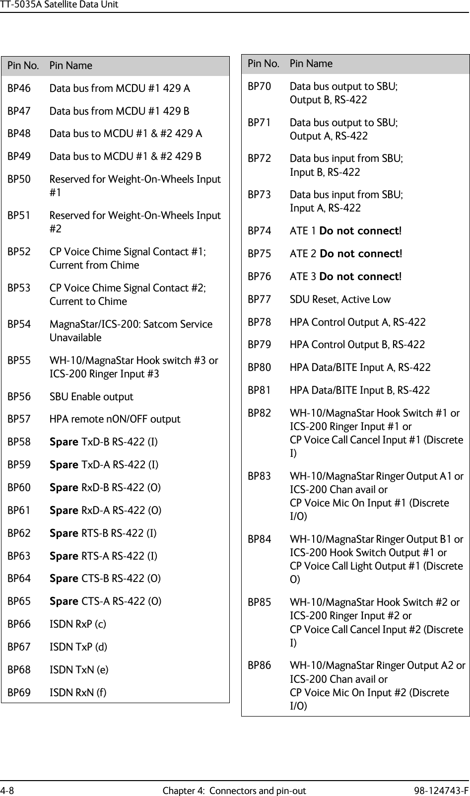
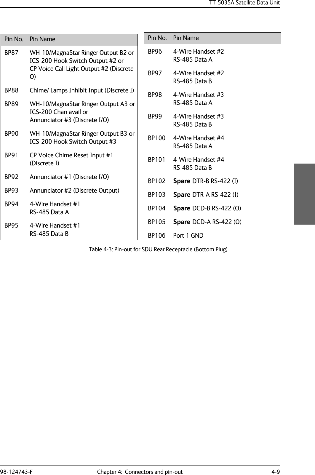
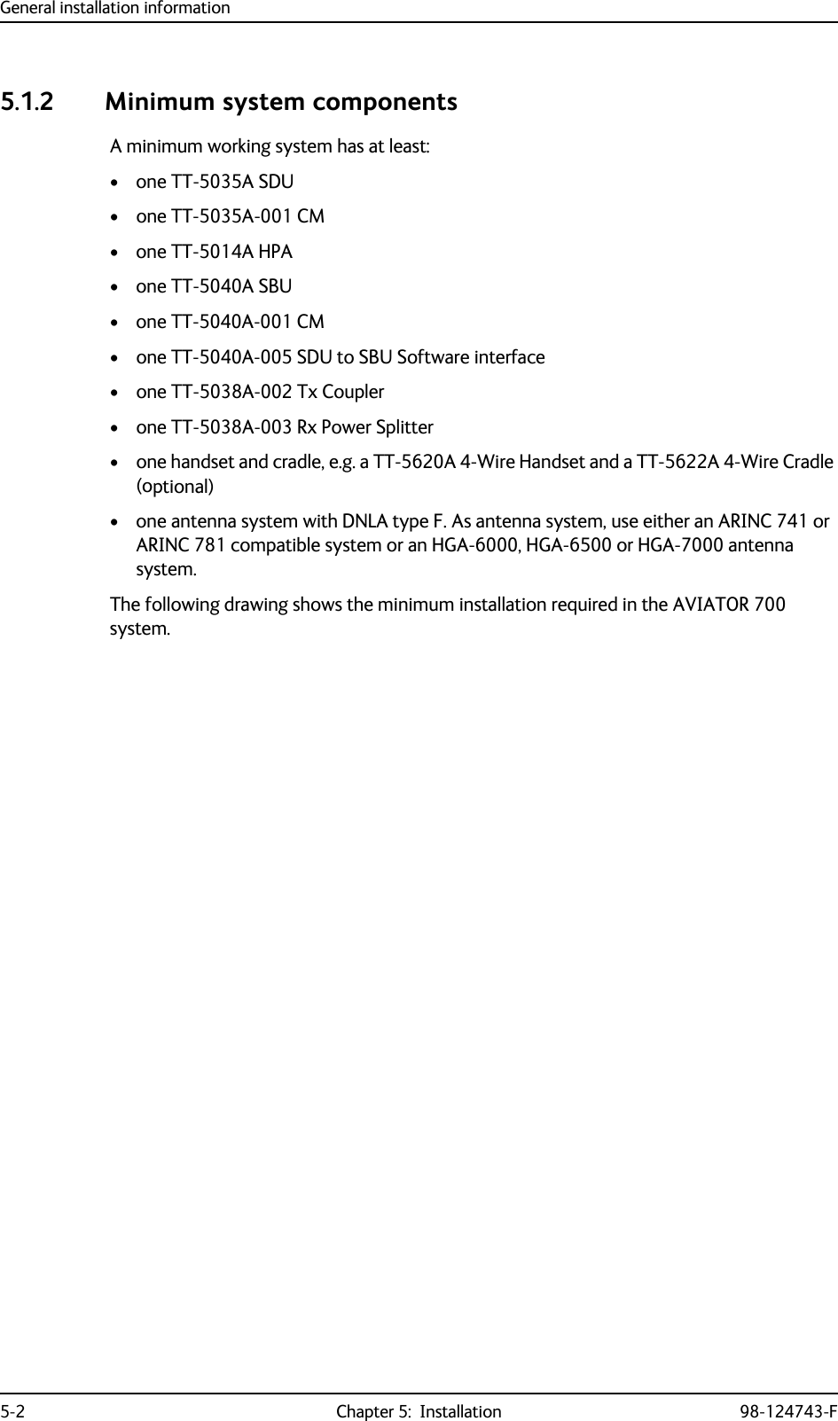
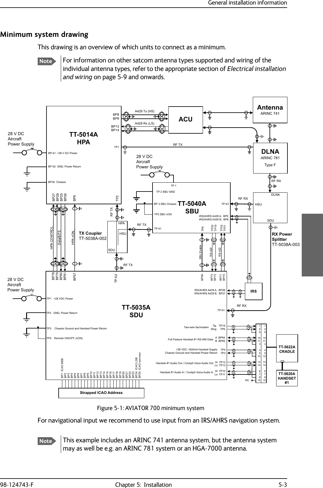
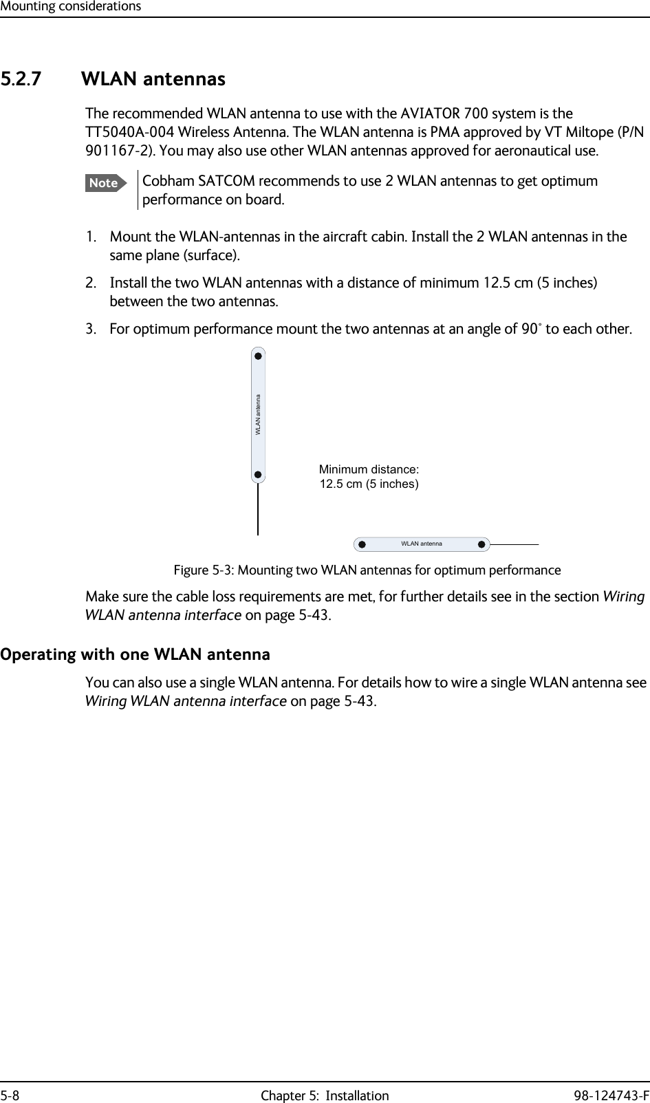
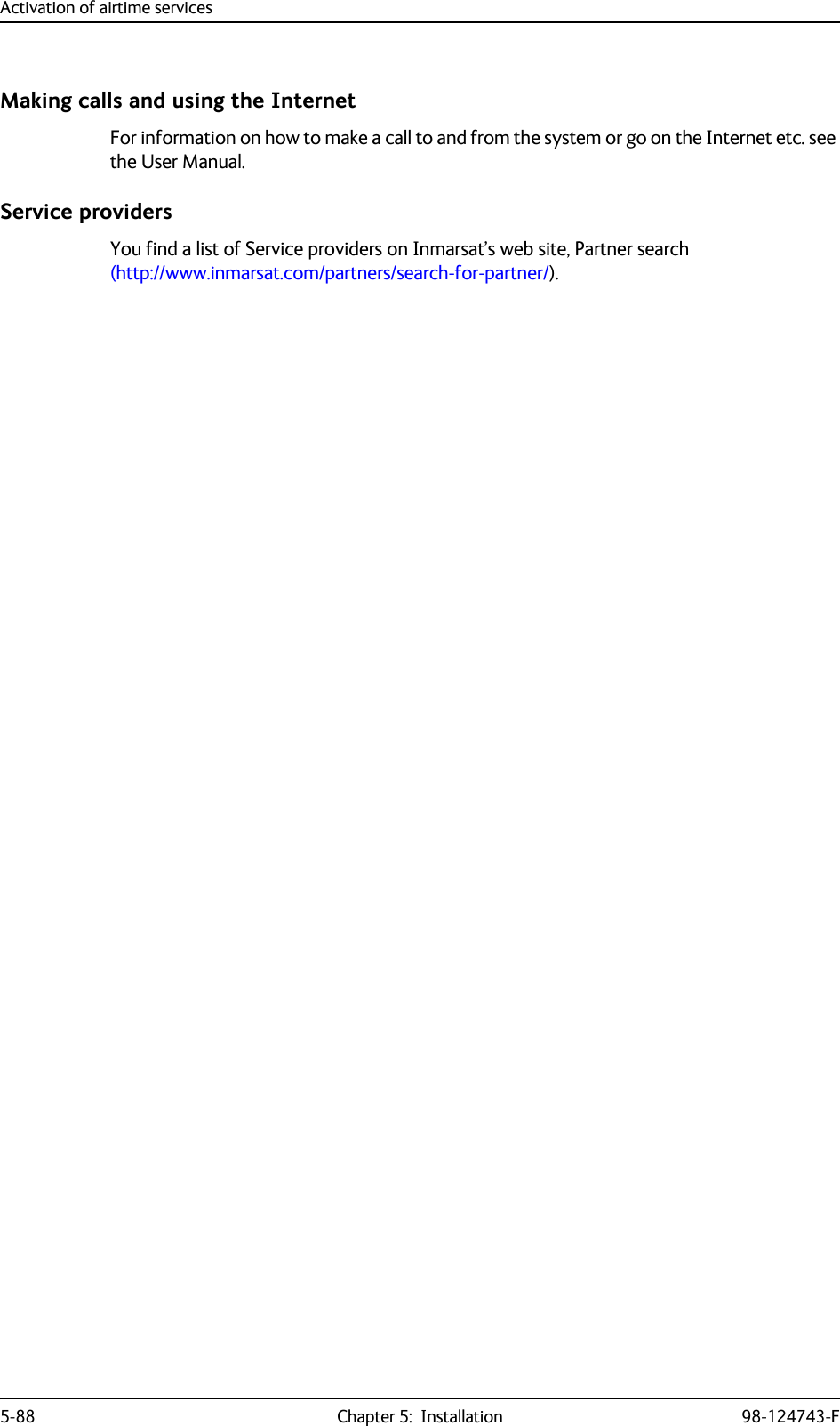
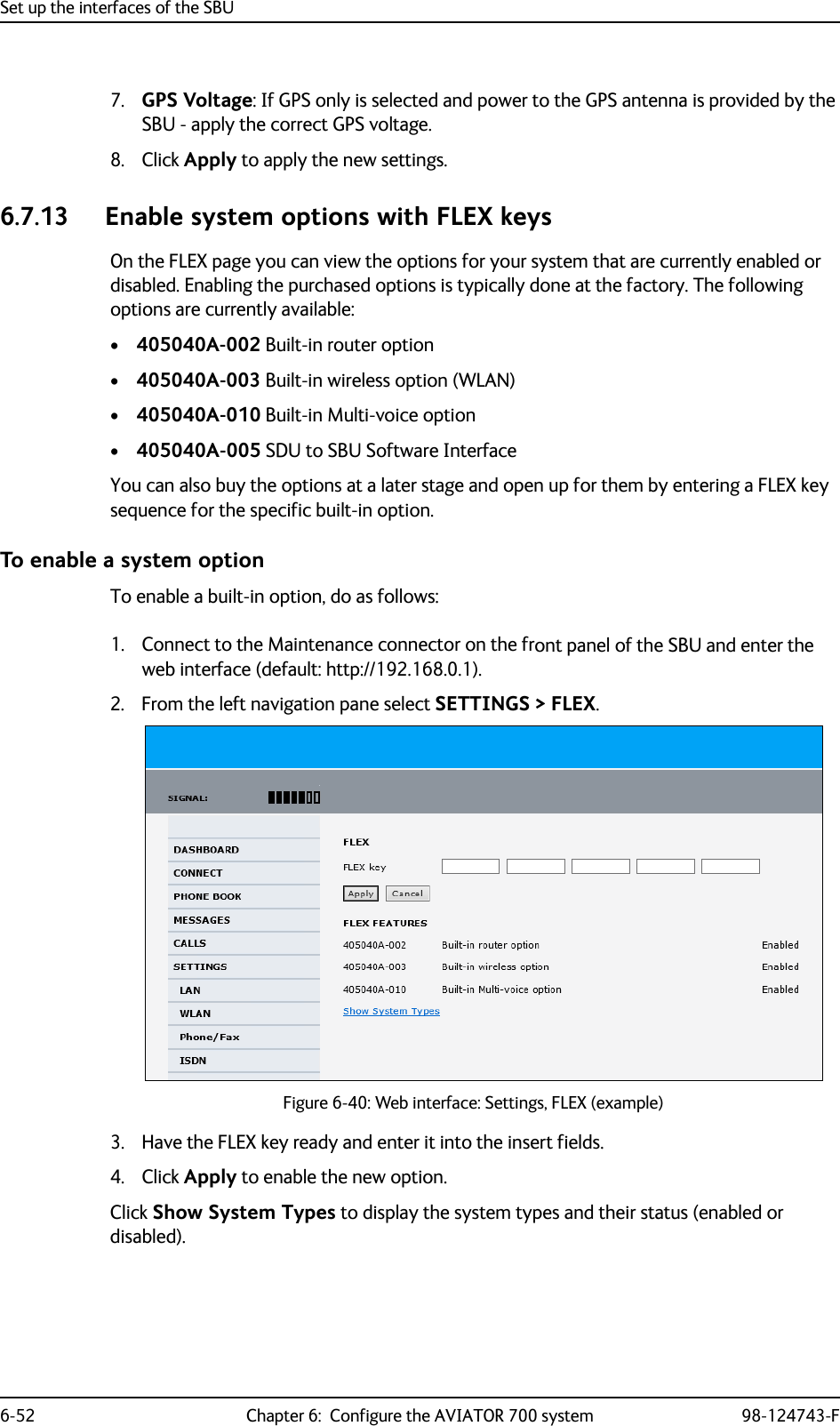
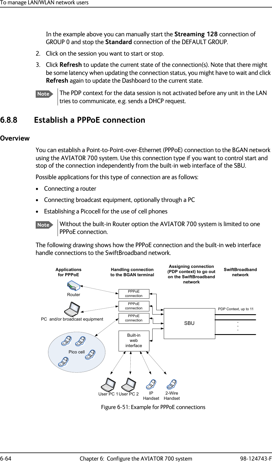
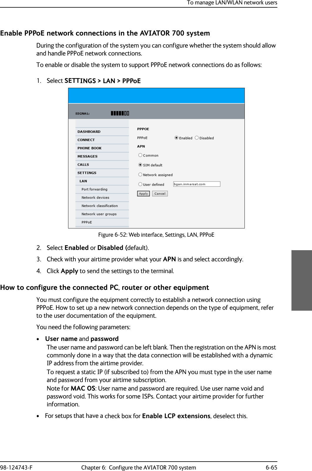
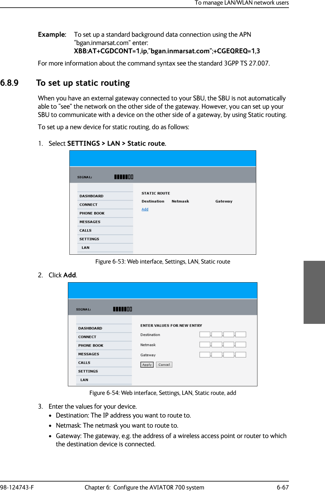
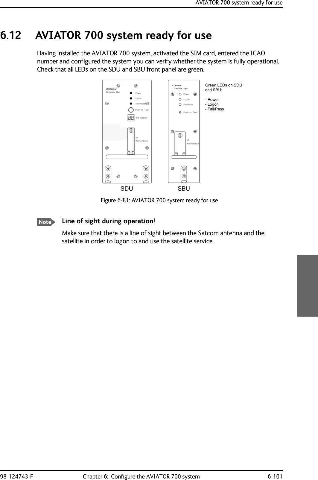
![Application98-124743-F Chapter 2: Introduction to the AVIATOR 700 2-112.2 Application2.2.1 Minimum systemA minimum working system has at least:•one TT-5035A SDU•one TT-5035A-001 CM• one TT-5014A HPA• one TT-5040A SBU• one TT-5040A-001 CM• one TT-5040A-005 SDU to SBU Software interface•one TT-5038A-002 Tx Coupler•one TT-5038A-003 Rx Power Splitter• one handset and cradle, e.g. a TT-5620A 4-Wire Handset and a TT-5622A 4-Wire Cradle (optional)• one antenna system with TT-5013A DNLA type F. As antenna system, use either an ARINC 741 or ARINC 781 antenna system.The minimum wiring required for an AVIATOR 700 system is described in the section Minimum system drawing on page 5-3.2.2.2 Part numbersApplicable model- and part numbersThis installation manual is for the AVIATOR 700 system and is applicable to the model and part numbers below:Part number Model number Description405035A TT-5035A Satellite Data Unit (SDU) [without CM] AVIATOR 700405035A-THD TT-5035A Satellite Data Unit (SDU) [without CM] AVIATOR 700D405035A-001 TT-5035A-001 Configuration Module (CM) for SDU for AVIATOR 700 and AVIATOR 700D405040A TT-5040A SwiftBroadband Unit (SBU) [without CM] for AVIATOR 700405040A-THD TT-5040A SwiftBroadband Unit (SBU) [without CM] for AVIATOR 700DTable 2-1: Model and part numbers for the AVIATOR 700 system (T&T units)](https://usermanual.wiki/Thrane-and-Thrane-A-S/AVIATOR700.Installation-Manual/User-Guide-4022295-Page-39.png)
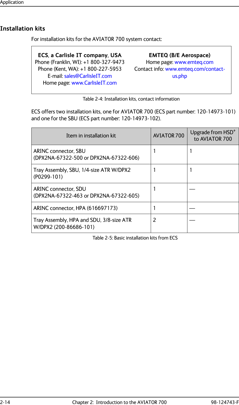
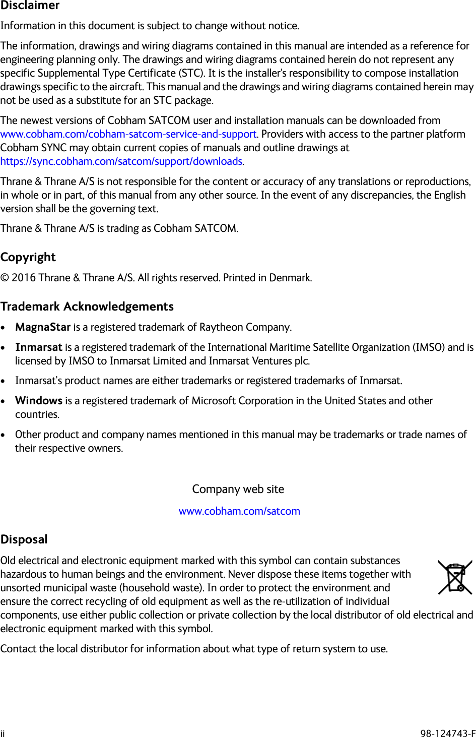
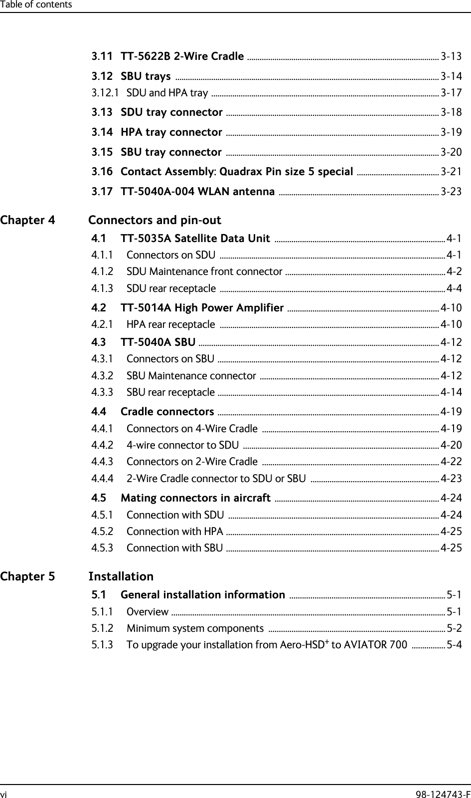
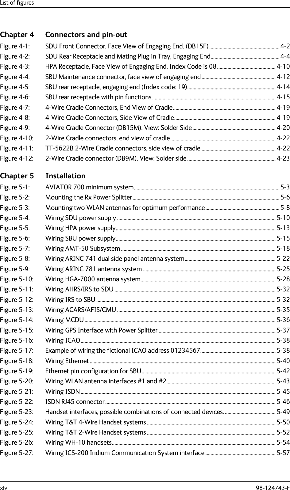
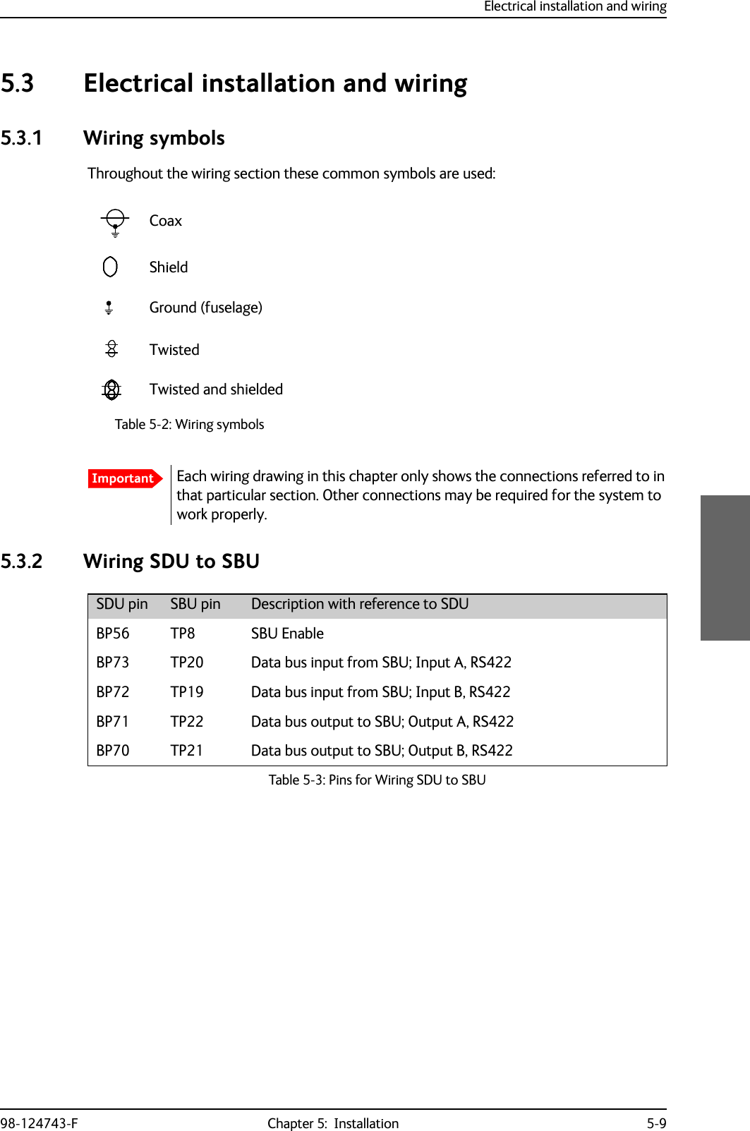
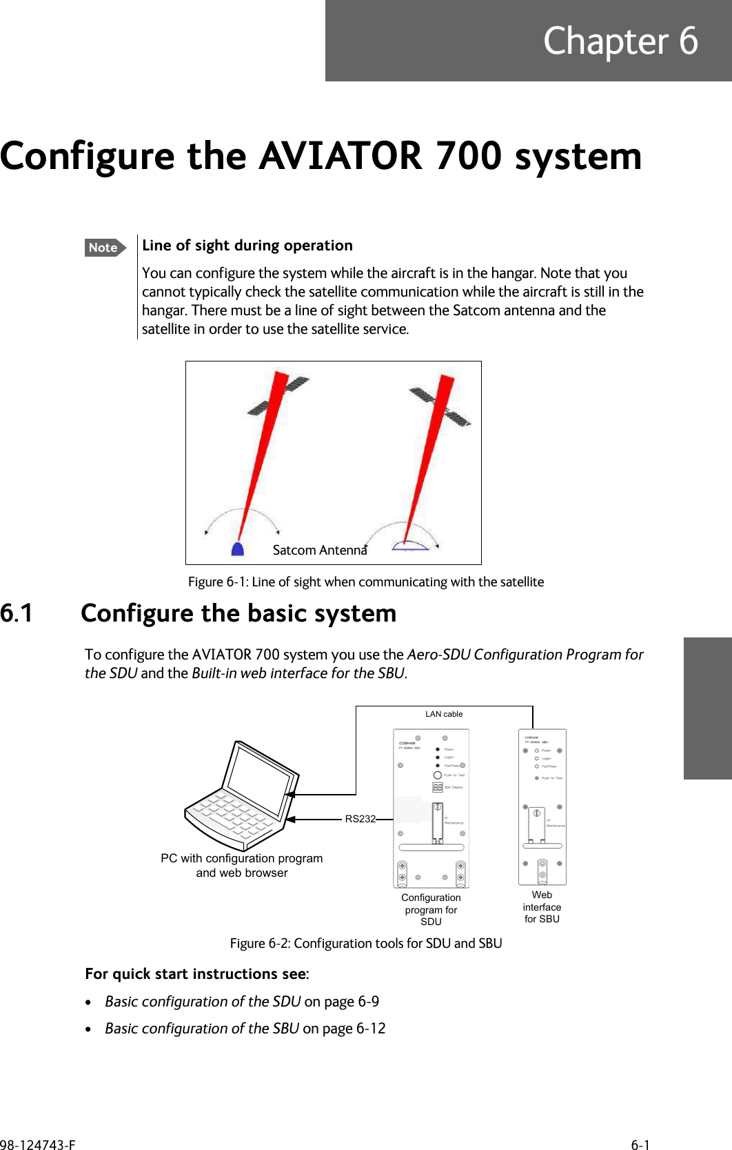
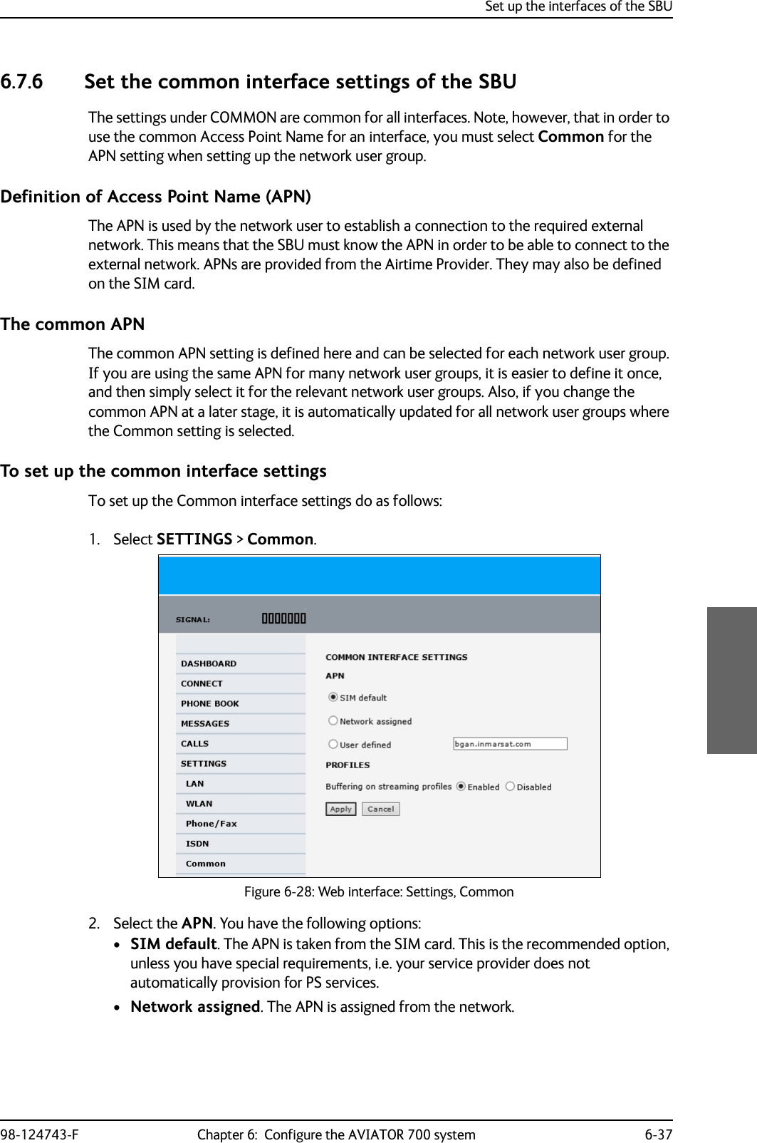
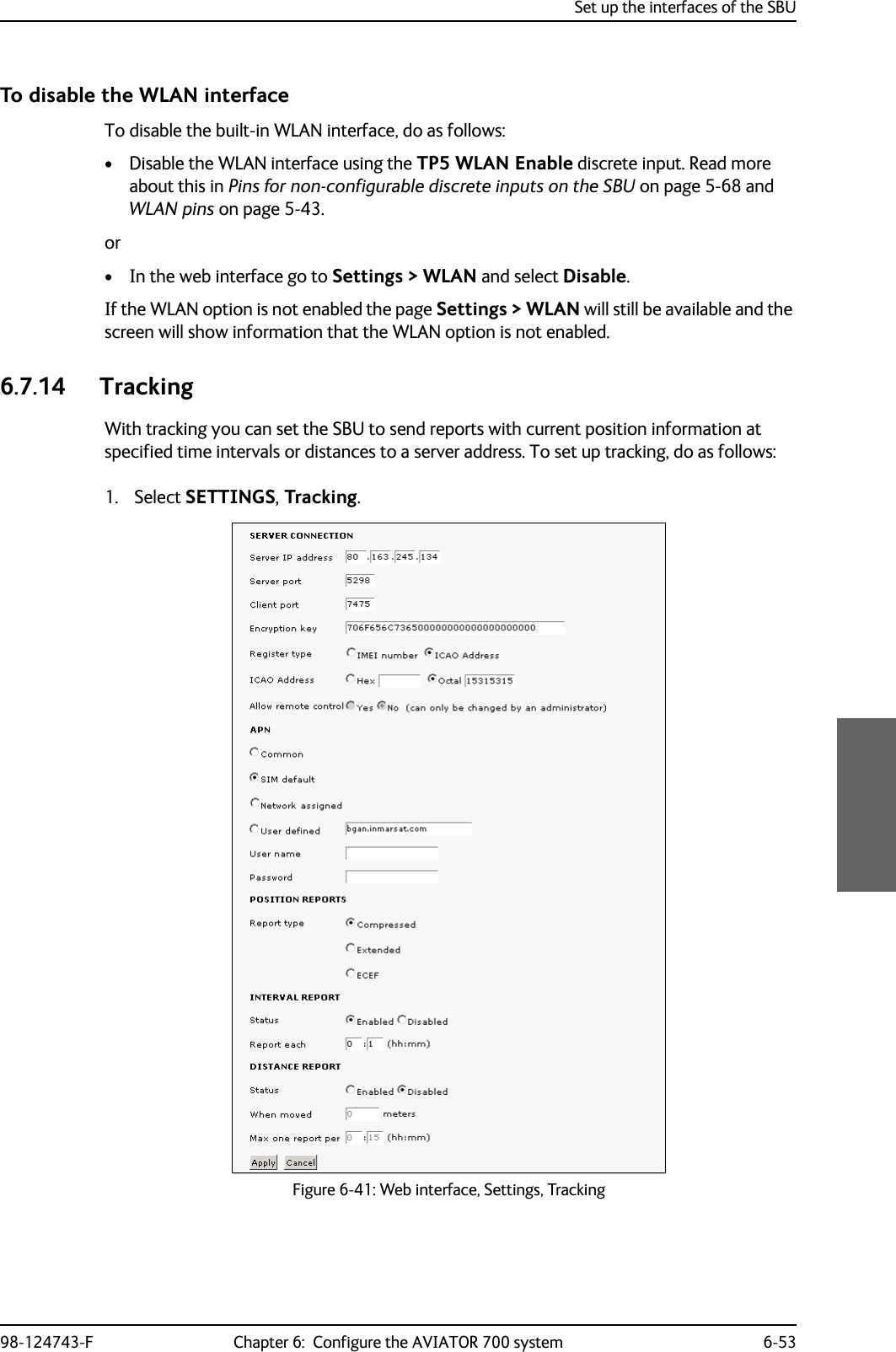
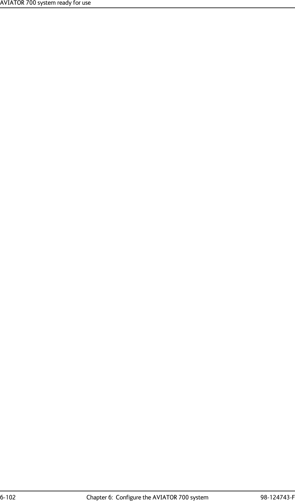
![TT-5013A DLNA Type F98-124743-F Chapter 3: Equipment drawings 3-93.7 TT-5013A DLNA Type FOriginal Manufacturer P/N: COMDEV 173628-101Figure 3-8: Outline drawing: DLNA Type F111405013A DLNA Type-F Outline drawingSHEET NO.MATERIAL AREV STATUSOF SHEETSREV LTR USED ON NEXT ASSY405013A DESCRIPTIONREVISIONSLTR DATE APPROVALA ORIGINAL 28-01-2010 HNB mm [ inches ] indication swoped 01-12-2010 HNC 405013A OEM from comdev 14-08-2015 JCJAPPLICATIONSHEET 1 OF 1DRAWING NO. TT94-130854CODE IDENT NO.94-130854-C.VSD SIZE A4FIRSTANGLEPROJECTIONDR. Hans Norring 28-01-10 TITLETelecommunications Engineering Copenhagen DenmarkSCALE 2:1CH. BMA 28-01-10AP. BMA 28-01-10AP. PT 21-09-11A/SUNLESS OTHERWISE SPECIFIEDDIMENSIONS ARE IN MILLIME-TRES AND TOLERANCES ARE INACCORDANCE WITH DS 22768.ANGLESLIN.DIM.405013APlacement of Thrane (Cobham) S/N LabelABCDEGJKHFA=10.350 [262.90]B= 9.550 [242.57]C= 8.464 [215.00]D= 7.764 [197.20]E= 9.852 [250.24]F=11.099±0.04 [281.51]±0.013G= 3.960 [100.50]H= 2.000 [50.79] MAXJ= 2.180 [55.30]K= 0.860 [21.90] Dimentions are in inches/[mm]Tolerances: ± 0.020/[0.5]Unless otherwise stated.CG [y,x,z]= 2,4[60.9], 5.09[129.3],0.70 [17.8].0Finish: mil-prf-85285 type 1, polyurethane #37038, cannoflage blackSurface roughness [1.6 micron] 63 microinchZ axisY axisX axisThe 405013A DLNA is identical to the COMDEV 173628-101 Type-F DLNA and the COMDEV 173628-101 MOD 01 Type-F DLNA.B C](https://usermanual.wiki/Thrane-and-Thrane-A-S/AVIATOR700.Installation-Manual/User-Guide-4022295-Page-61.png)
200 m,incl. circuit breaker[2](GND, Power Return)25 mThe cable should be as short as possible.[3](Chassis Ground)25 mConnect directly to aircraft chassis.Table 5-5: Requirements to SDU power cablesNoteMaximum cable lengths are calculated and listed in the section Power cables, allowed cable lengths on page 5-81.](https://usermanual.wiki/Thrane-and-Thrane-A-S/AVIATOR700.Installation-Manual/User-Guide-4022295-Page-114.png)
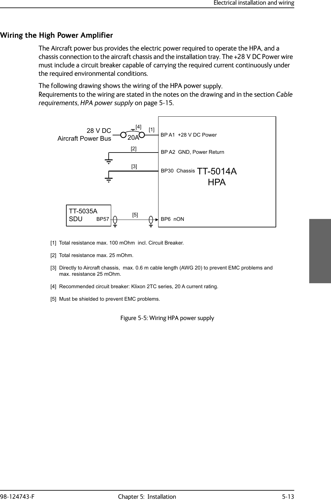
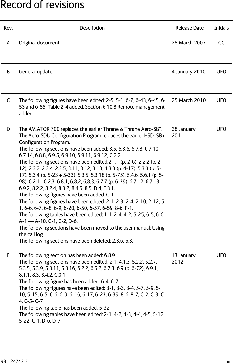
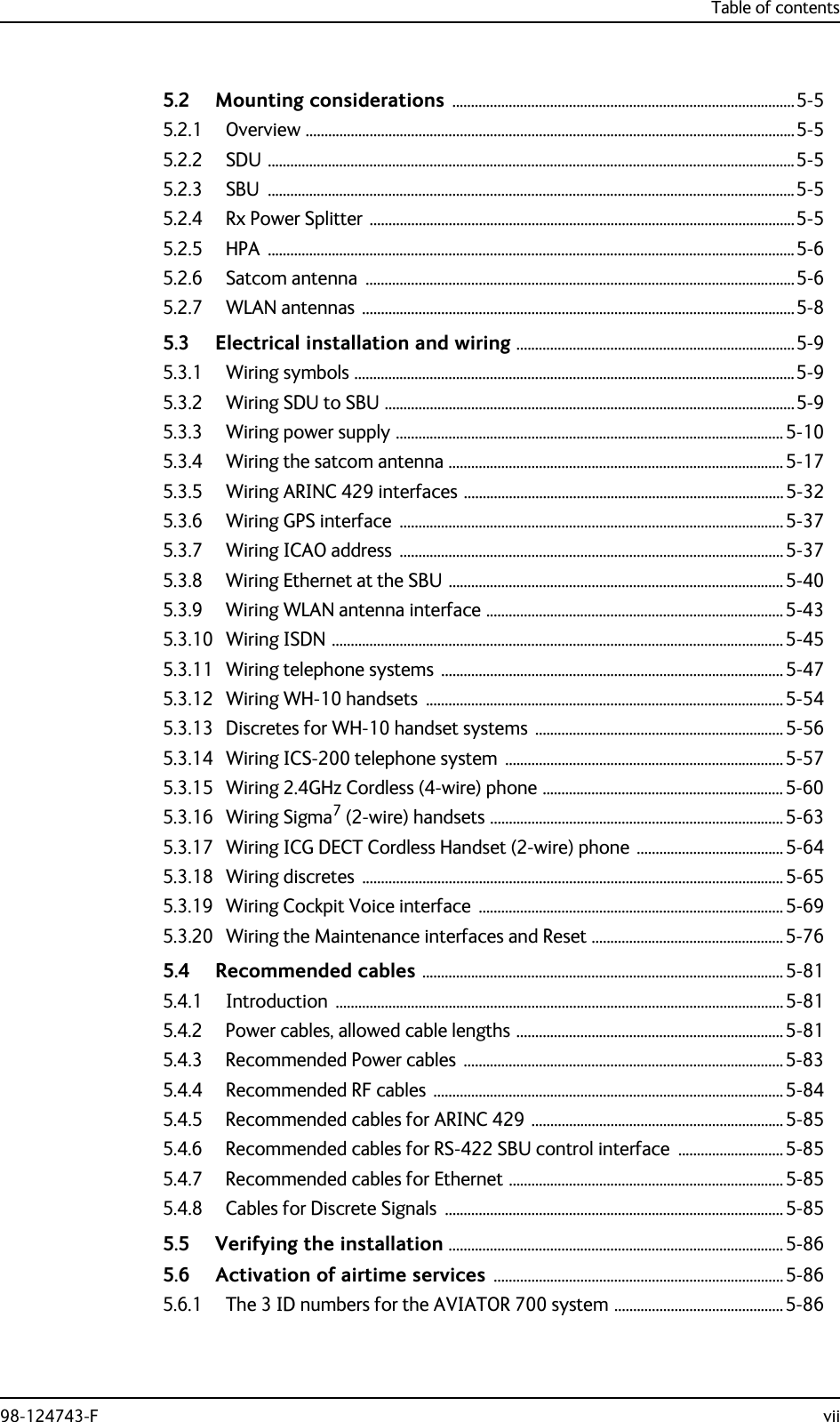
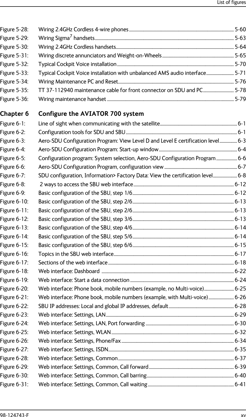
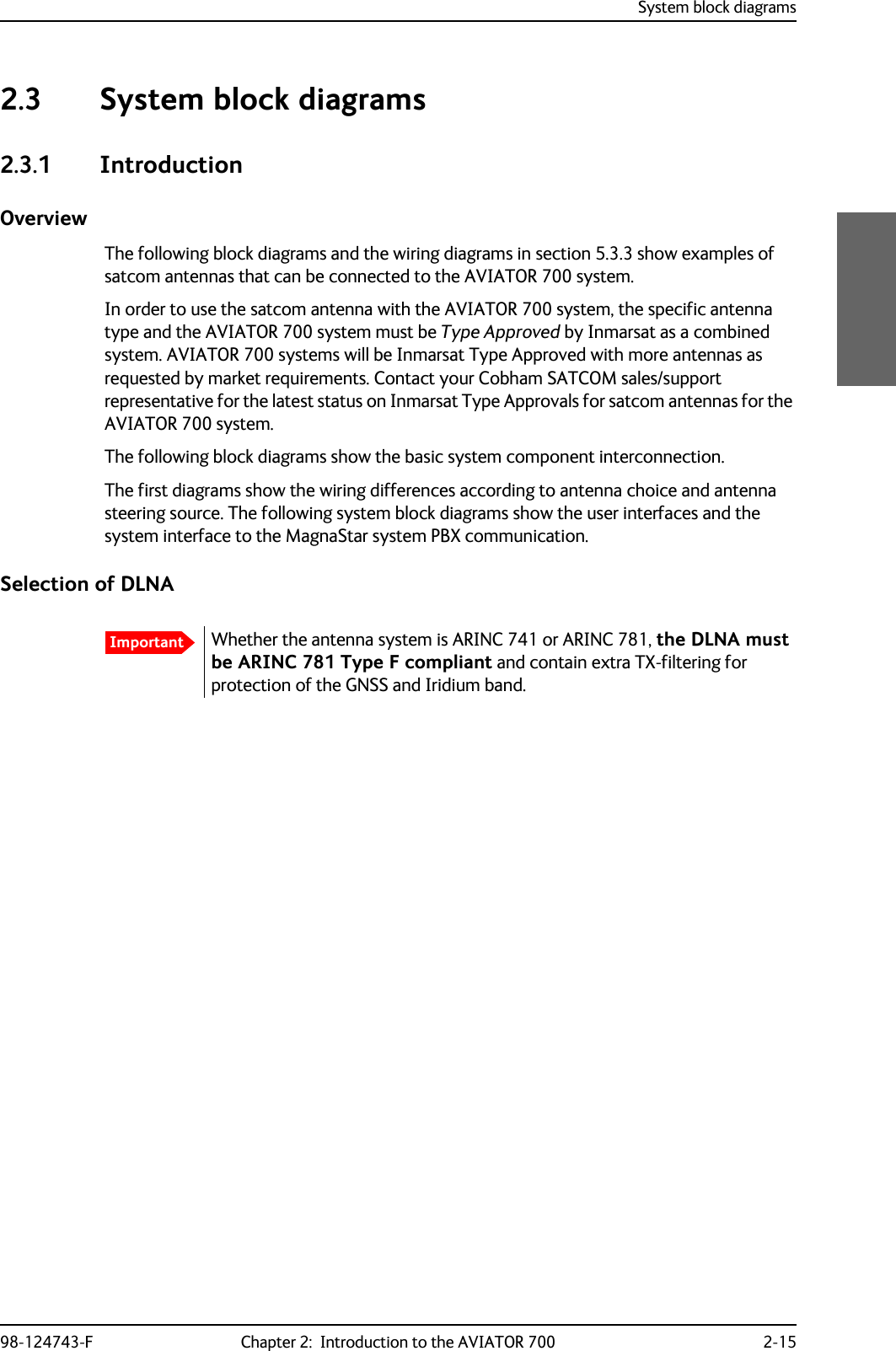
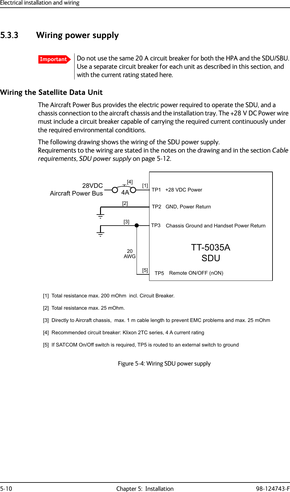
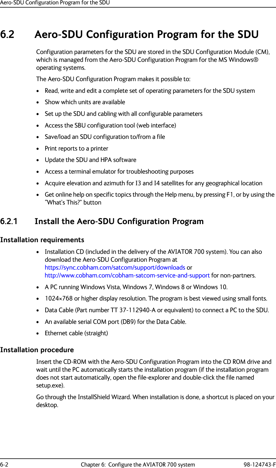
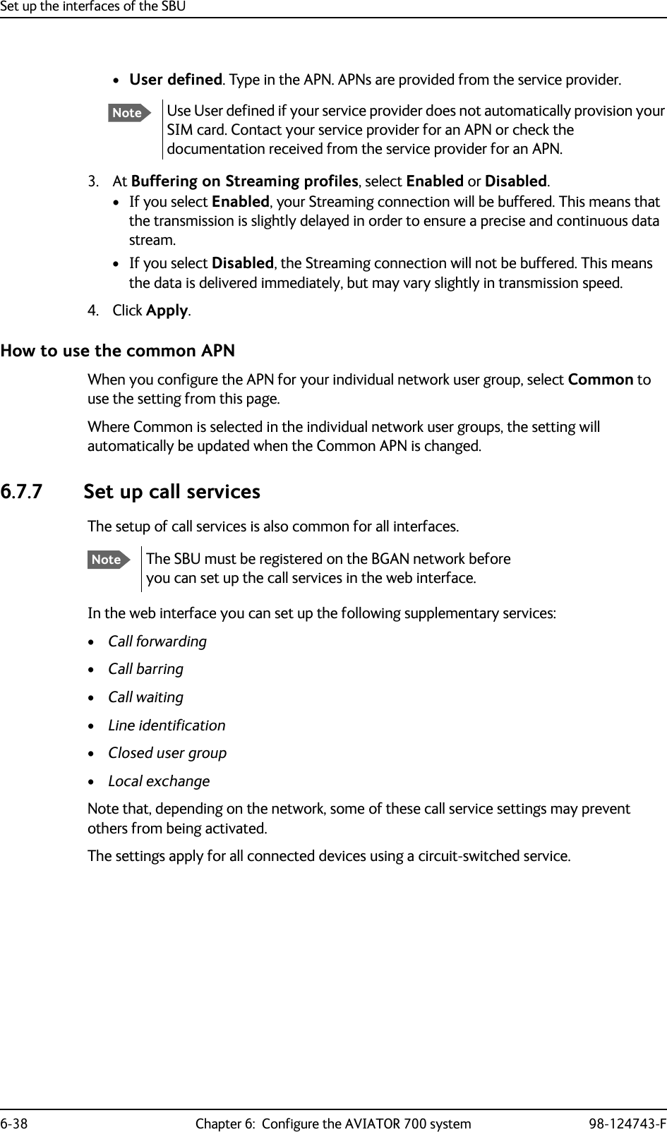
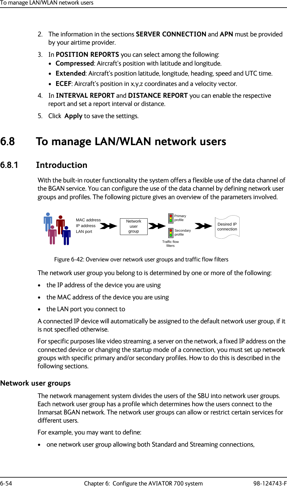
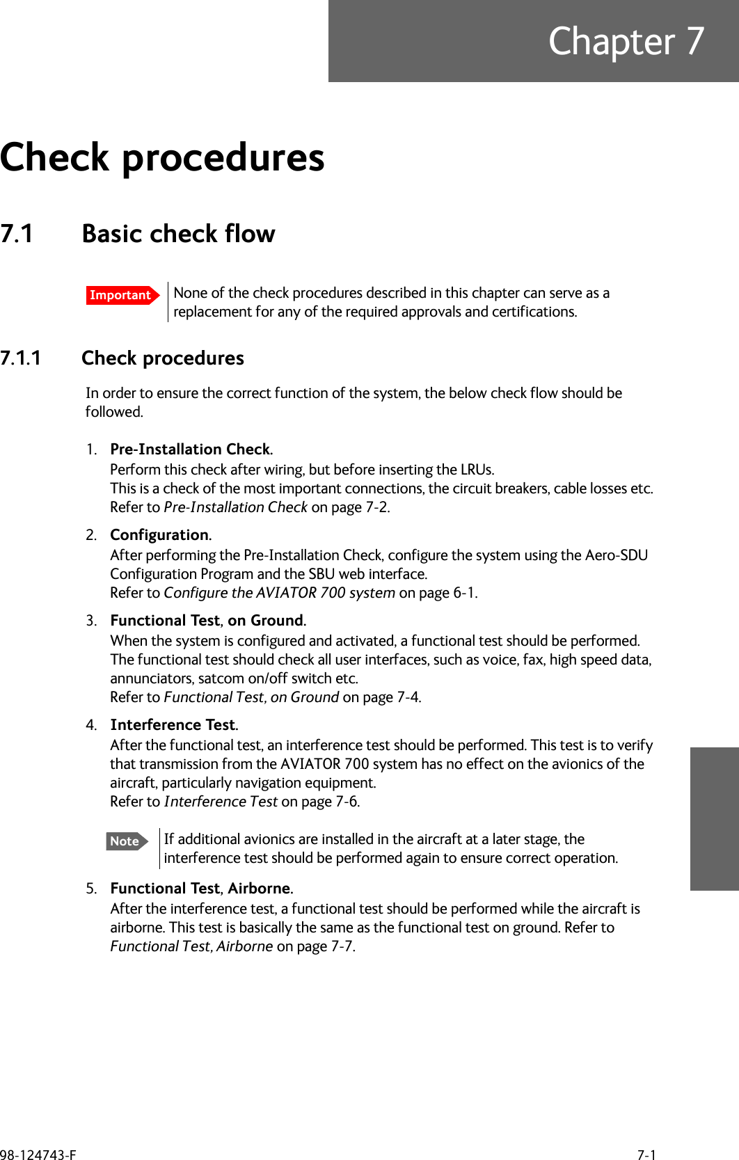
![Electrical installation and wiring98-124743-F Chapter 5: Installation 5-15Cable requirements, HPA power supplyWiring the SwiftBroadband UnitThe Aircraft power bus interfaces supply the electric power required to operate the SBU. They also supply a chassis connection to the aircraft chassis and the installation tray for EMC purposes. The +28 V DC Power wire must include a circuit breaker capable of carrying the required current continuously under the required environmental conditions.The following drawing shows the wiring of the SBU to the Aircraft Power Bus.SBU maximum power consumptionIn the AVIATOR 700 system the SBU does not supply power for neither the HPA nor external satcom antennas. See Table A-3 on page A-6 for the total power consumption of the SBU (including CM).Cableaa. The cable numbers refer to the numbers stated on the wiring drawing in the section Wiring the High Power Amplifier on page 5-13.Max. Resistance Other Requirements[1] (+28 V DC Power) 100 m,incl. circuit breaker[2] (GND, Power Return) 25 m[3] (Chassis) 25 mConnect directly to aircraft chassis.[5] (nON) - Must be shielded to avoid EMC problems.Table 5-8: Requirements to HPA power cablesNoteMaximum cable lengths are calculated and listed in the section Power cables, allowed cable lengths on page 5-81.Figure 5-6: Wiring SBU power supply77$6%8>@ 73*1'3RZHU5HWXUQ9'&$LUFUDIW3RZHU%XV>@7RWDOUHVLVWDQFHPD[P2KPLQFO&LUFXLW%UHDNHU>@'LUHFWO\WR$LUFUDIW*URXQGZLWKOHVVWKDQPFDEOH7RWDOUHVLVWDQFHPD[P2KP>@'LUHFWO\WRLQVWDOODWLRQWUD\DQGDLUFUDIWFKDVVLVPD[P2KPUHVLVWDQFH>@5HFRPPHQGHGFLUFXLWEUHDNHU.OL[RQ7&VHULHV$FXUUHQWUDWLQJ>@,I6$7&202Q2IIVZLWFKLVUHTXLUHG73LVURXWHGWRDQH[WHUQDOVZLWFKWRJURXQG%3739'&3RZHU&KDVVLV*URXQG>@$>@>@73 6%8Q21212))>@](https://usermanual.wiki/Thrane-and-Thrane-A-S/AVIATOR700.Installation-Manual/User-Guide-4022295-Page-117.png)
![Electrical installation and wiring98-124743-F Chapter 5: Installation 5-17Cable requirements, SBU power supply5.3.4 Wiring the satcom antennaCable lossesSelection of DLNAUse the 405013A DLNA Type F.The DLNA used in the AVIATOR 700 system must contain improved Tx-filtering for protection of the GNSS and Iridium band. Cableaa. The cable numbers refer to the numbers stated on the wiring drawing in the section Figure 5-6: Wiring SBU power supply.Max. resistance Other requirements[1] (+28 V DC Power) 250 m, incl. circuit breaker[2] (GND, Power Return) 25 mThe cable should be as short as possible, max. 1 m.[3] (Chassis Ground) 25 mConnect directly to aircraft chassis.Table 5-10: Requirements to SBU power cablesNoteFor maximum allowed cable lengths, see Power cables, allowed cable lengths on page 5-81.NoteDuring installation, measure and write down the cable loss of the RF cables. You need these values later on for the SDU in the Aero-SDU Configuration Program and for the SBU in the web interface during configuration of the system. For further details see Basic configuration of the SDU on page 6-9 or the online help in the Aero-SDU Configuration Program and Configure RF settings of the SBU on page 6-50.Important](https://usermanual.wiki/Thrane-and-Thrane-A-S/AVIATOR700.Installation-Manual/User-Guide-4022295-Page-119.png)
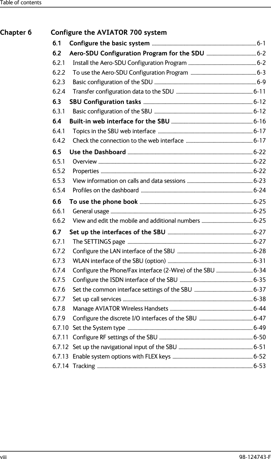
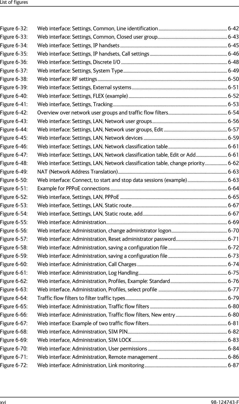
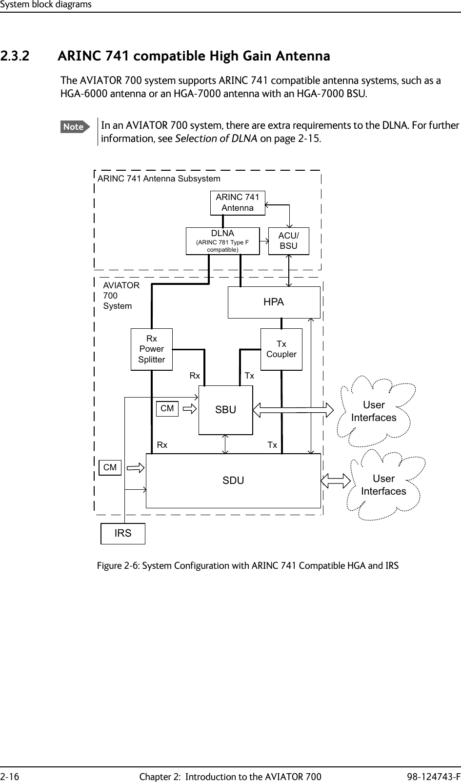
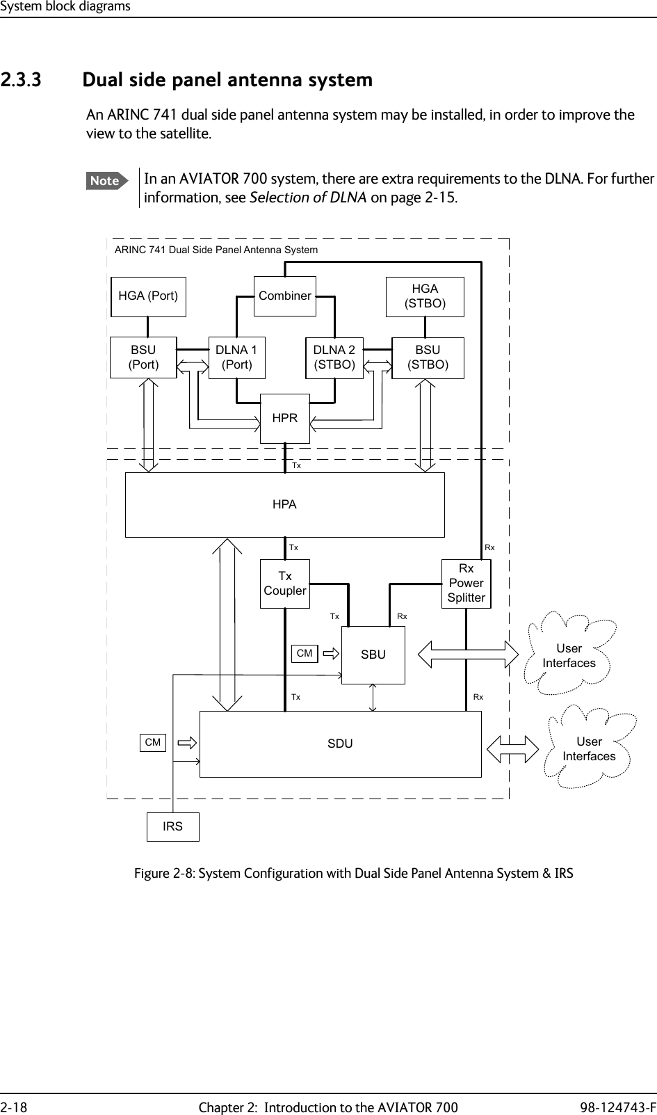
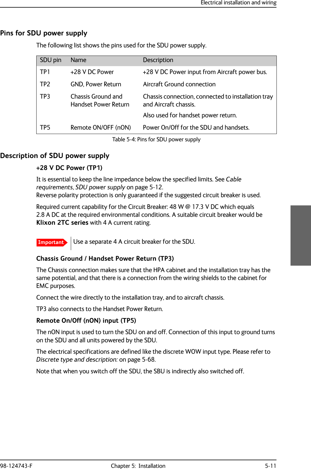
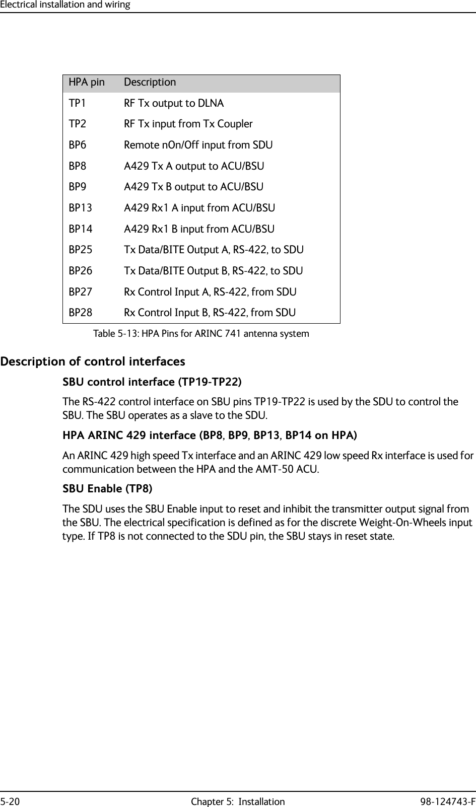
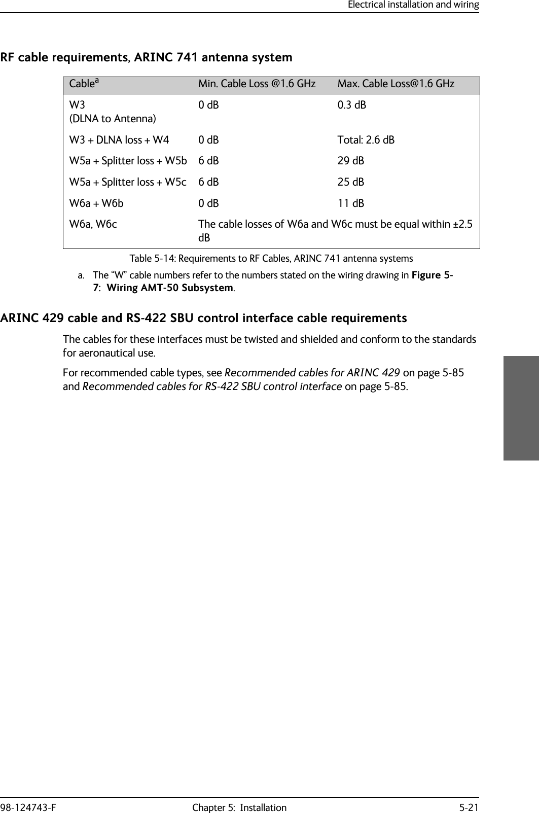
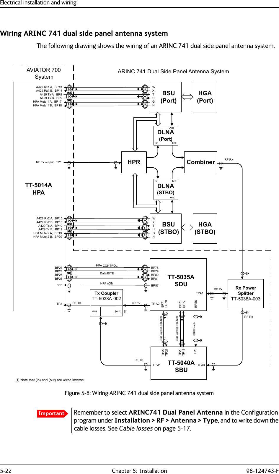
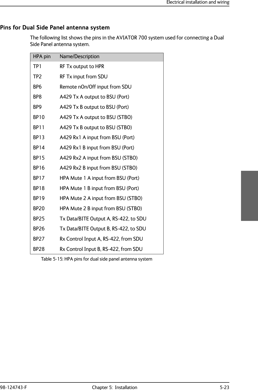
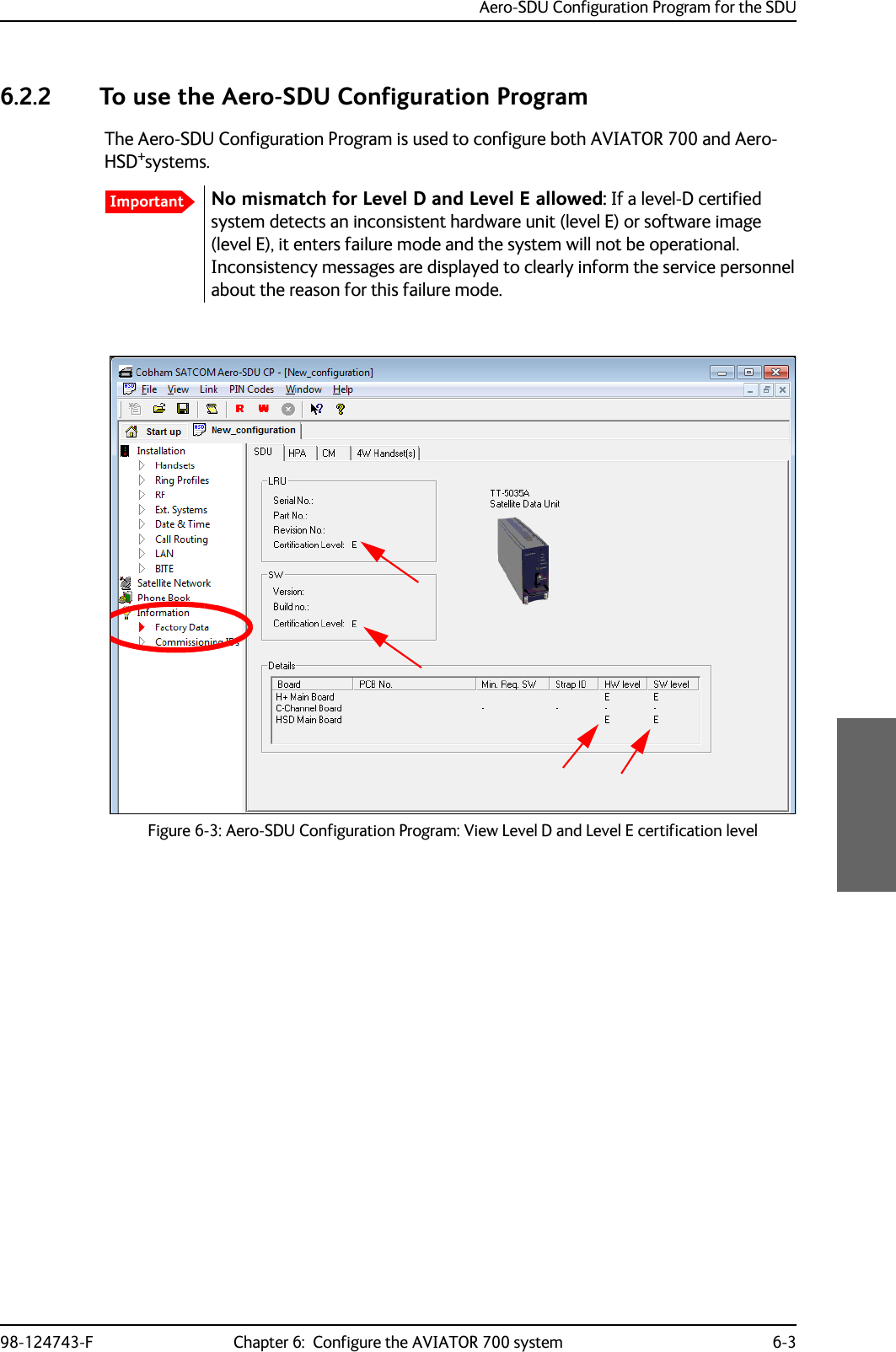
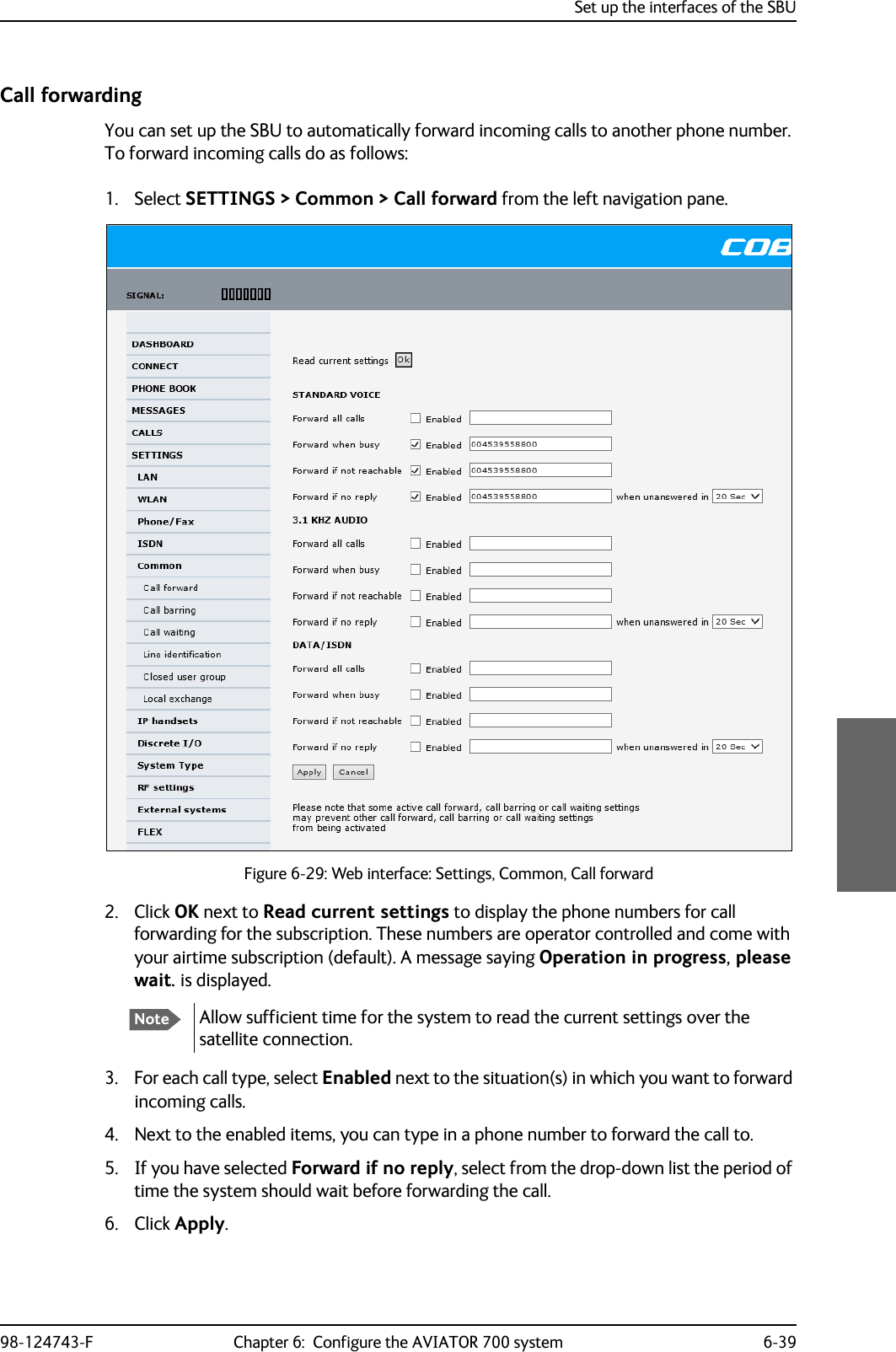
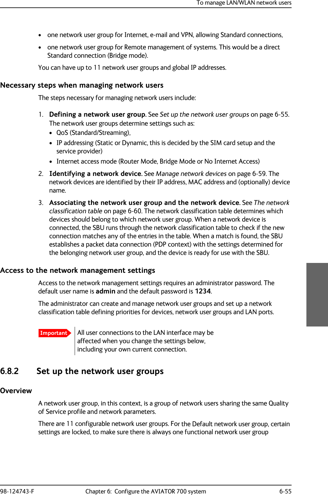
![Electrical installation and wiring5-18 Chapter 5: Installation 98-124743-FWiring ARINC 741 antenna systemsAn example of an ARINC 741 antenna system is the AMT-50 system. The following drawing shows the wiring for an AVIATOR 700 system using an AMT-50 antenna.NoteIn an AVIATOR 700 system, the DLNA must be ARINC 781 Type F compatible and contain extra TX-filtering for protection of the GNSS and Iridium band.Figure 5-7: Wiring AMT-50 Subsystem7;&RXSOHU77$>@77$6'8$07$QWHQQD$5,1&7\SH)'/1$3RZHU6SOLWWHUG%#*+]+686'8'/1$5;3RZHU6SOLWWHU77$77$6%86%8&RQWURO56%3%3%3%3%373737373736%8&RQWURO566%8(QDEOH73$73$6'8RXW+3$LQ+687377$+3$73%3%3%3%3+3$Q21%3 %3%3%3%3%3+3$&21752/'DWD%,7(73$73$5)5;&2$;>@>@5)5;&2$;>@: >@5)7;&2$;>@5)7;&2$;>@>@ 5)7;&2$;>@5)5;&2$;>@$07$&8$%*+:>@>@%3%3%3%3$7[+6$5[/6$076XEV\VWHP:D:E:F:F:D :E>@7KHFDEOHORVVRI:EHWZHHQ'/1$DQGDQWHQQDPXVWEH WRG%#*+]>@7KHWRWDOFDEOHORVVRI:'/1$ORVV:PXVWEH WRG%#*+]>@7KHWRWDOFDEOHORVVRI:D6SOLWWHUORVV:EPXVWEH WRG%#*+]>@7KHWRWDOFDEOHORVVRI:D6SOLWWHUORVV:FPXVWEH WRG%#*+]>@7KHWRWDOFDEOHORVVRI:D:EPXVWEH WRG%#*+]>@7KHFDEOHORVVHVRI:DDQG:FPXVWEHHTXDOZLWKLQG%#*+]>@1RWHWKDWLQDQGRXWDUHZLUHGLQYHUVH](https://usermanual.wiki/Thrane-and-Thrane-A-S/AVIATOR700.Installation-Manual/User-Guide-4022295-Page-120.png)
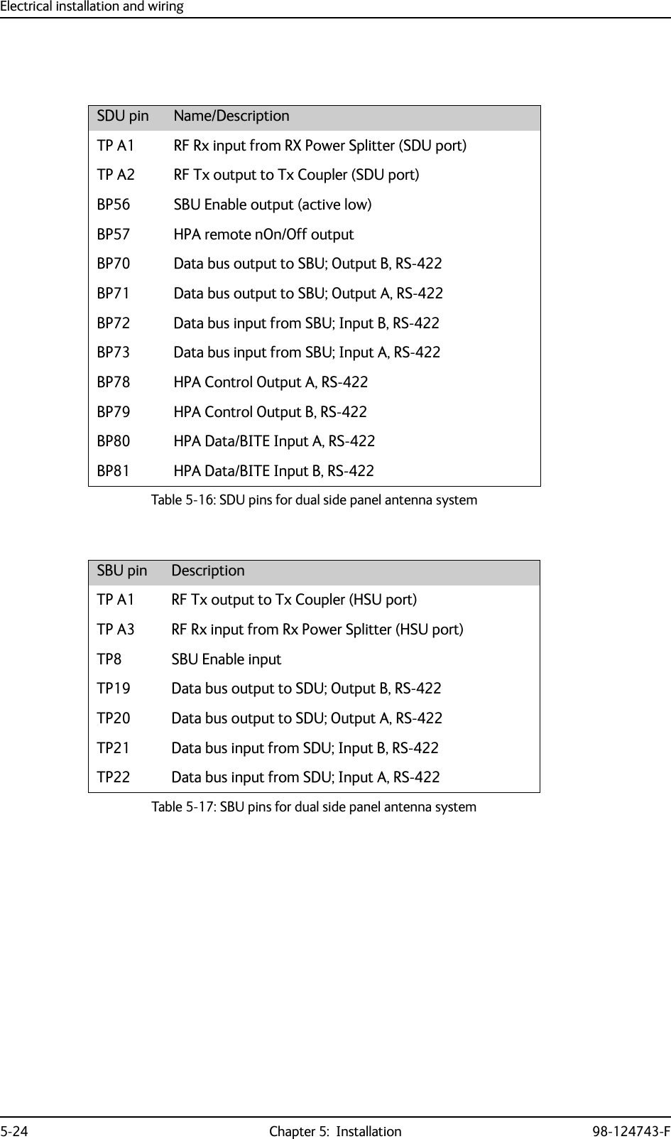
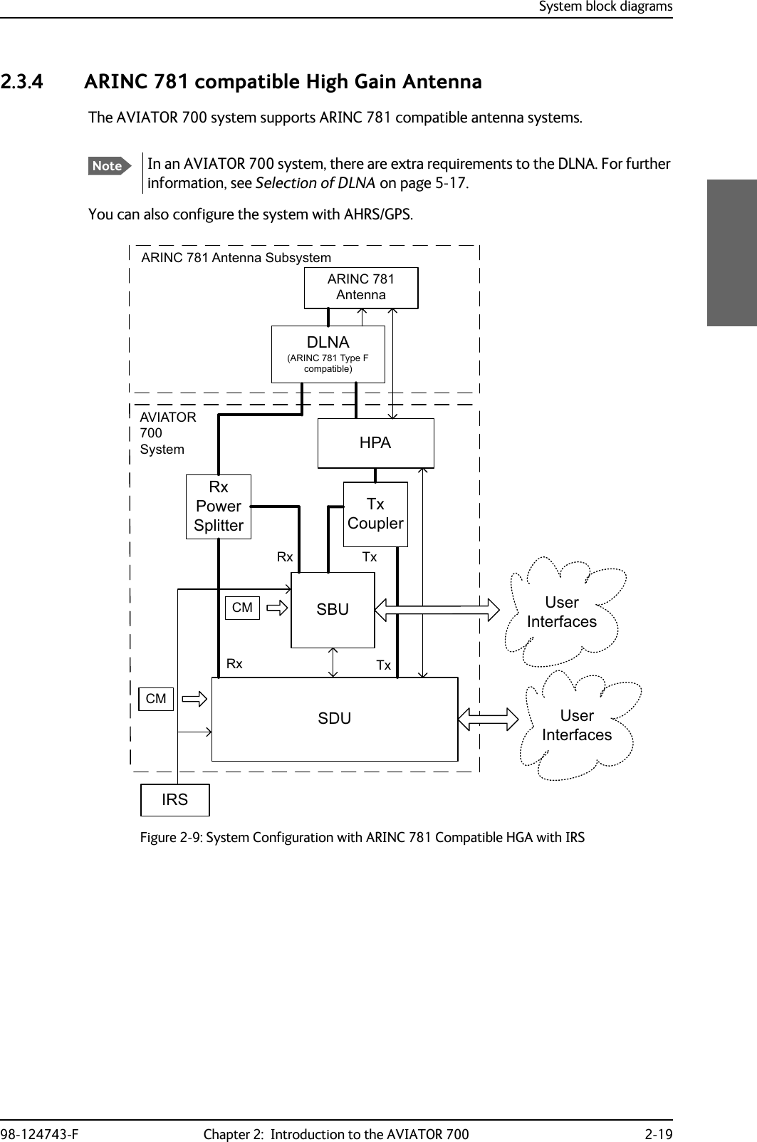
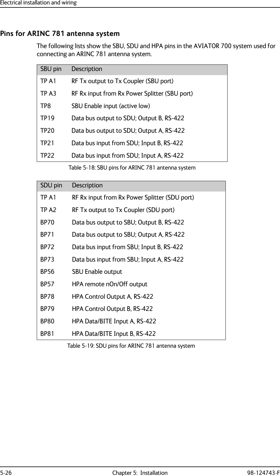
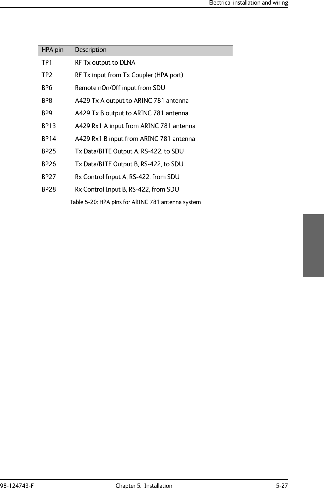
![Electrical installation and wiring98-124743-F Chapter 5: Installation 5-25Wiring ARINC 781 antenna systemsThe following drawing shows the wiring for an AVIATOR 700 system using an ARINC 781 antenna system.Requirements to the cables are stated on the drawing and in the next section RF cable requirements, ARINC 781 antenna systems.Figure 5-9: Wiring ARINC 781 antenna system7;&RXSOHU77$>@77$6'8$5,1&$QWHQQD$5,1&7\SH)'/1$3RZHU6SOLWWHUG%#*+]+686'8 '/1$5;3RZHU6SOLWWHU77$77$6%86%8&RQWURO56%3%3%3%3%373737373736%8&RQWURO566%8(QDEOH73$73$6'8RXW>@+3$LQ+687377$+3$73%3%3%3%3+3$Q21%3 %3%3%3%3%3+3$&21752/'DWD%,7(73$73$5)5;&2$;>@>@5)5;&2$;>@: >@5)7;&2$;>@5)7;&2$;>@>@ 5)7;&2$;>@5)5;&2$;>@>@7KHFDEOHORVVRI:EHWZHHQ'/1$DQGDQWHQQDPXVWEH WRG%#*+]>@7KHWRWDOFDEOHORVVRI:'/1$ORVV:PXVWEH WRG%#*+]>@7KHWRWDOFDEOHORVVRI:D6SOLWWHUORVV:EPXVWEH WRG%#*+]>@7KHWRWDOFDEOHORVVRI:D6SOLWWHUORVV:FPXVWEH WRG%#*+]>@7KHWRWDOFDEOHORVVRI:D:EPXVWEH WRG%#*+]>@7KHFDEOHORVVHVRI:DDQG:FPXVWEHHTXDOZLWKLQG%#*+]>@1RWHWKDWLQDQGRXWDUHZLUHGLQYHUVH:>@>@:E :D:F:F:D :E%3%3%3%3$7[+6$5[/6 ](https://usermanual.wiki/Thrane-and-Thrane-A-S/AVIATOR700.Installation-Manual/User-Guide-4022295-Page-127.png)
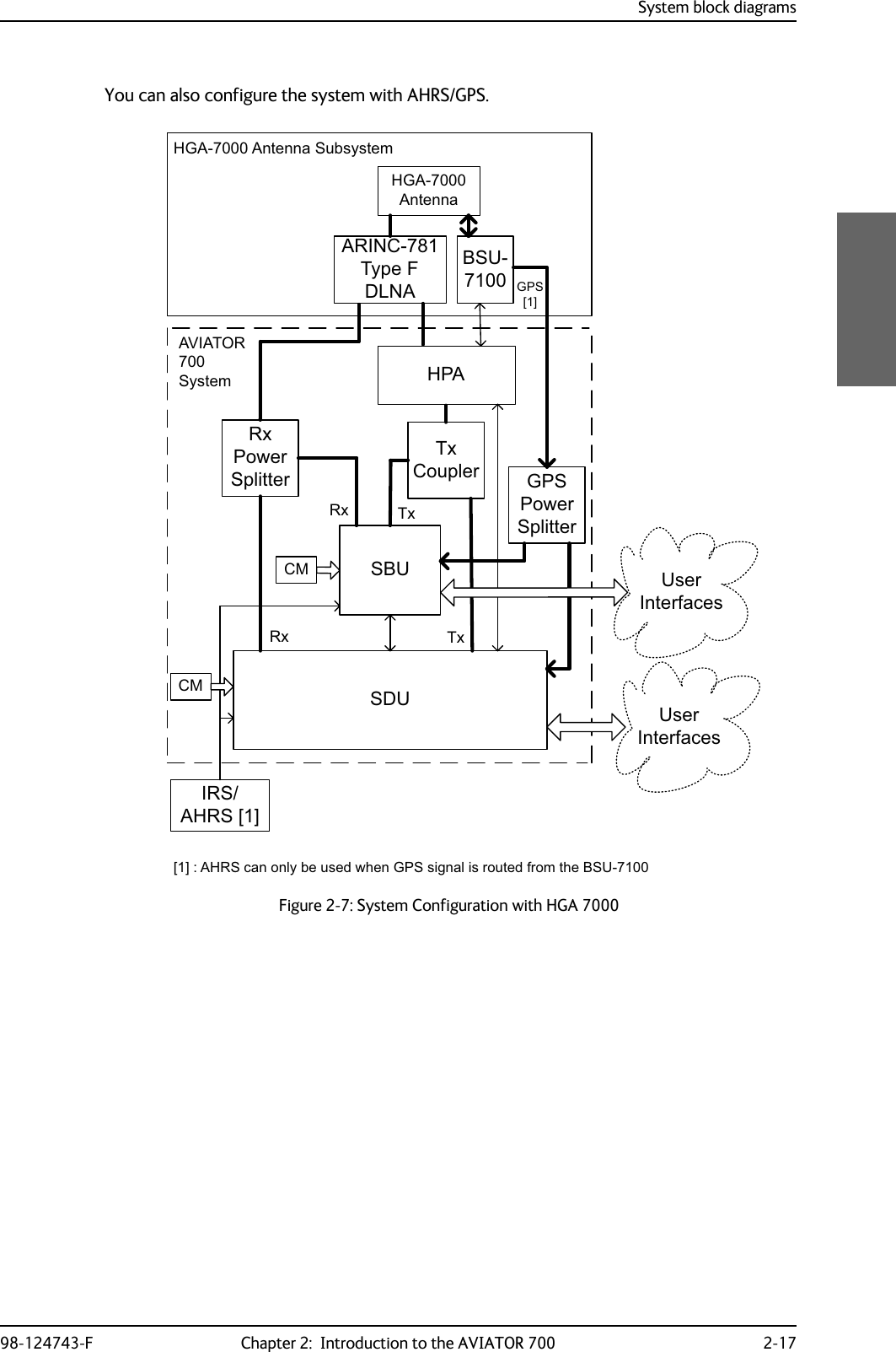
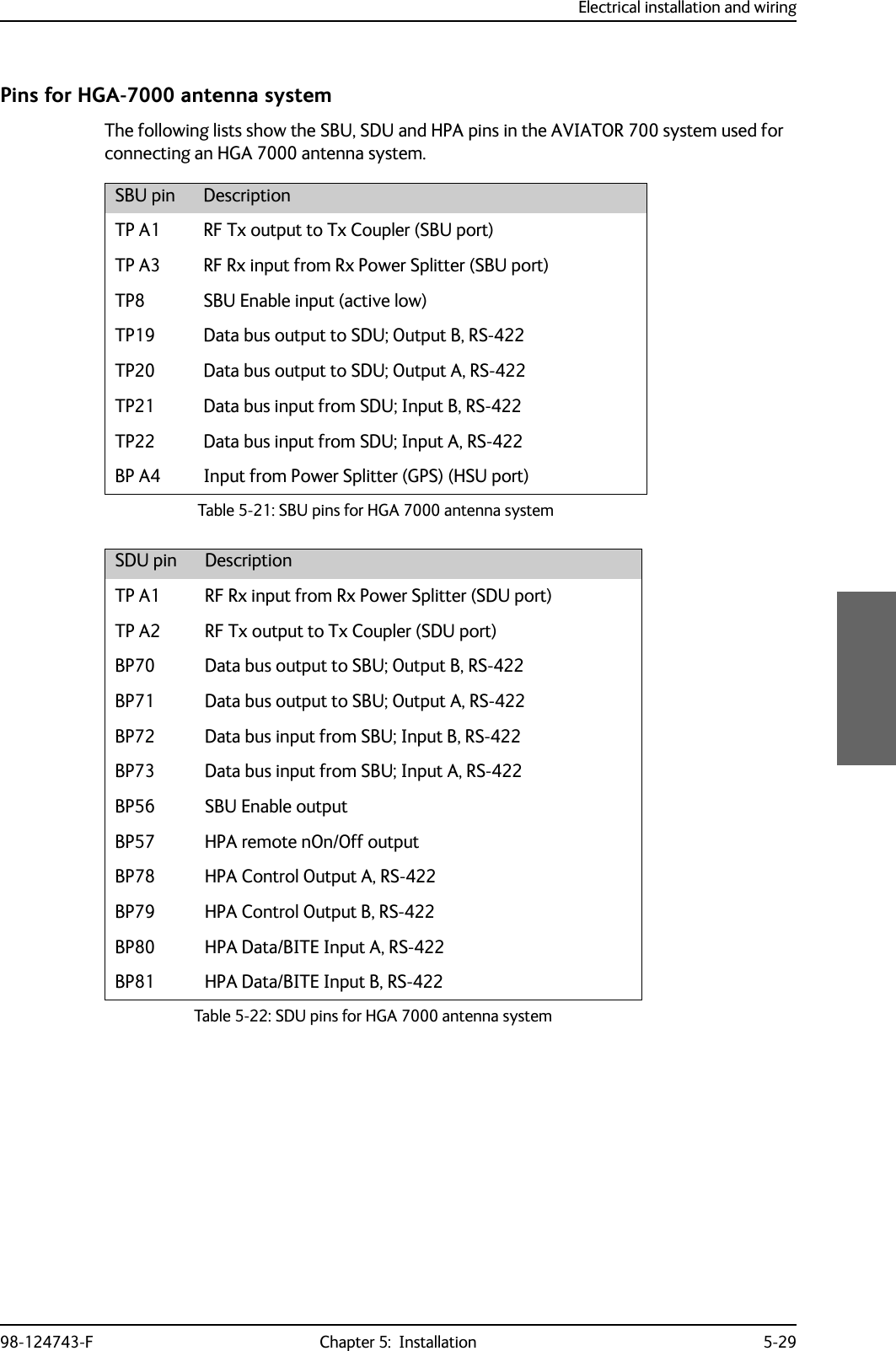
![Electrical installation and wiring5-28 Chapter 5: Installation 98-124743-FWiring HGA 7000 antenna systemFigure 5-10: Wiring HGA-7000 antenna system7;&RXSOHU77$77$6'8%68$5,1&7\SH)'/1$3RZHU6SOLWWHU5;G%#*+]+686'8 '/1$5;3RZHU6SOLWWHU77$77$6%86%8&RQWURO56%3%3%3%3%373737373736%8&RQWURO566%8(QDEOH73$73$6'8RXW+3$LQ+687377$+3$73%3%3%3%3+3$Q21%3 %3%3%3%3%3+3$&21752/'DWD%,7(73$73$5)5;&2$;>@>@5)5;&2$;>@:>@5)7;&2$;>@5)7;&2$;>@>@ 5)7;&2$;>@5)5;&2$;>@>@ 7KHFDEOHORVVRI:EHWZHHQ'/1$DQGDQWHQQDPXVWEH WRG%#*+]>@ 7KHWRWDOFDEOHORVVRI:'/1$ORVV:PXVWEH WRG%#*+]>@ 7KHWRWDOFDEOHORVVRI:D6SOLWWHUORVV:EPXVWEH WRG%#*+]>@ 7KHWRWDOFDEOHORVVRI:D6SOLWWHUORVV:FPXVWEH WRG%#*+]>@ 7KHWRWDOFDEOHORVVRI:D:EPXVWEH WRG%#*+]>@ 7KHFDEOHORVVHVRI:DDQG:FPXVWEHHTXDOZLWKLQG%#*+]>@ *36FDEOHV:E:FDQG:GPXVWEHZLUHGLI$+56LVXVHGLQVWHDGRI,56&DEOH:DPXVWEHZLUHGLQERWKFDVHV7KHWRWDOFDEOHORVVHVRI:D:E:FPXVWEH WRG%#*+] 7KHWRWDOFDEOHORVVHVRI:D:E:GPXVWEH WRG%#*+]:>@>@:E:D:F:F:D :E%3%3%3%3$7[+6$5[/6:; +---%+--/Y$177;+*$5;3RZHU6SOLWWHU*36G%#*+]+686'8 '/1$5;3RZHU6SOLWWHU77$ :D:E>@:F>@-EOXH -UHG:G>@73$%3$ILQ>@](https://usermanual.wiki/Thrane-and-Thrane-A-S/AVIATOR700.Installation-Manual/User-Guide-4022295-Page-130.png)
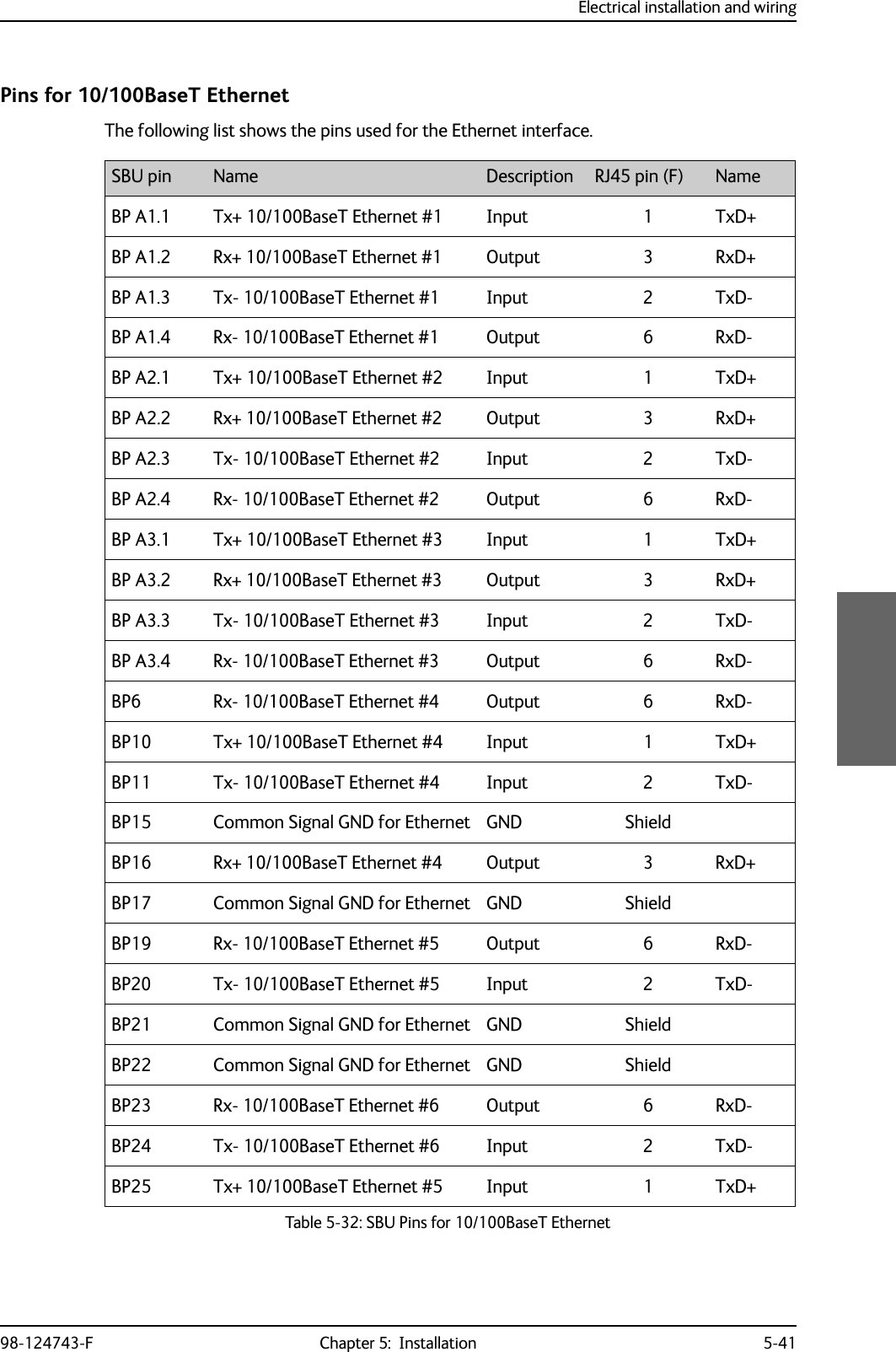
![Electrical installation and wiring5-42 Chapter 5: Installation 98-124743-FWiring of RJ45 connector to Quadrax connectorThe physical layer conforms to IEEE standard 802.3 [1], Chapter 14: “Twisted Pair medium attachment unit”, except for the connector type. To be compliant with [1], use an RJ45 female connector for the user interface. The below drawing shows the corresponding RJ45 connection. The SBU is configured as Data communication Equipment (DCE), i.e. TX +/- are input and RX +/- are outputs.Figure 5-19: Ethernet pin configuration for SBUCommon Signal GND (BP15, BP17, BP21, BP22 and BP27)Common Signal GND is used to connect the shield of the Ethernet cables for Ethernet #4, #5 and #6 on the SBU. The shield for each cable is connected according to Figure 5-18: Wiring Ethernet. The shield of the Ethernet cables for Ethernet #1, #2 and #3 is connected to the shield of the Quadrax connectors.BP26 Rx+ 10/100BaseT Ethernet #5 Output 3 RxD+BP27 Common Signal GND for Ethernet GND ShieldBP28 Tx+ 10/100BaseT Ethernet #6 Input 1 TxD+BP29 Rx+ 10/100BaseT Ethernet #6 Output 3 RxD+SBU pin Name Description RJ45 pin (F) NameTable 5-32: SBU Pins for 10/100BaseT Ethernet (Continued)6%8SLQ73$$$6KLHOG7[' 7;LQSXWQF7[' 7; LQSXW5['5;RXWSXWQF5[' 5; RXWSXWQFQF 2KP TXDGUD[WZLVWHGDQGVKLHOGHGSDLUV7[' 7;LQSXWQF7[' 7; LQSXW5['5;RXWSXWQF5[' 5; RXWSXWQFQFDQGVKLHOGHGSDLUV6%8SLQ6%8'&(%3 %3%35-IHPDOHWR'7(%3%3&DEOH&DEOH 2KP TXDGUD[WZLVWHG](https://usermanual.wiki/Thrane-and-Thrane-A-S/AVIATOR700.Installation-Manual/User-Guide-4022295-Page-144.png)
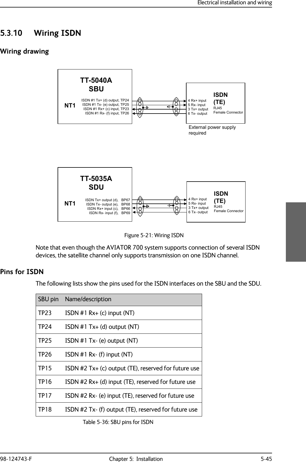
![Electrical installation and wiring5-46 Chapter 5: Installation 98-124743-FDescription of SBU and SDU ISDN interfaceThe SBU and SDU have one ISDN interface each. The ISDN of the SDU uses the Swift64 service (I3), the ISDN of the SBU uses the SwiftBroadband service (I4). Each interface has its own ISDN controller and front end. The Euro ISDN S-bus interface is configured as the network side of the NT1 interface i.e. Rx is an input and Tx is an output Please note that this configuration of input and output differs from the configuration of the 10BaseT Ethernet, RS-422 and RS-232 PC interface input/output (valid for SBU and SDU).The ISDN interface can address up to 8 ISDN devices. The SBU ISDN interface supports 56/64kbps data rate and G4 Fax on the SwiftBroadband connection. You can also use the SBU ISDN interface to make an AMBE2 or 3.1 kHz audio call. The SDU interface supports 56/64kbps data rate and G4 Fax on Swift64.There is no DC power on the ISDN interface of the SBU. All ISDN devices connected to the SBU must be powered externally.To be compliant with ISO8877 [2] and the ISDN connector specification defined by ITU I.420 [6], an RJ45 Female Connector must be connected to the four-wire ISDN lines from the SBU. The SBU includes an internal 100 termination resistor to support cable lengths up to 100 meters (109 yards). Make sure the other end of the cable is terminated properly.Cable requirements, ISDN• Cable for the ISDN interface: 100 4-wire shielded cable.• The conductors must be twisted in pairs.• Supported cable lengths: up to 100 meters (328 feet).SDU pin Name/DescriptionBP67 ISDN Tx+ output (d)BP68 ISDN Tx- output (e)BP66 ISDN Rx+ input (c)BP69 ISDN Rx- input (f)Table 5-37: SDU pins for ISDNImportantFigure 5-22: ISDN RJ45 connector,6'15[,QSXWF,6'17[2XWSXWG,6'17[2XWSXWH,6'15[,QSXWIQRWFRQQHFWHG5-IHPDOHFRQQHFWRUQRWFRQQHFWHGQRWFRQQHFWHGQRWFRQQHFWHG5-IHPDOH](https://usermanual.wiki/Thrane-and-Thrane-A-S/AVIATOR700.Installation-Manual/User-Guide-4022295-Page-148.png)
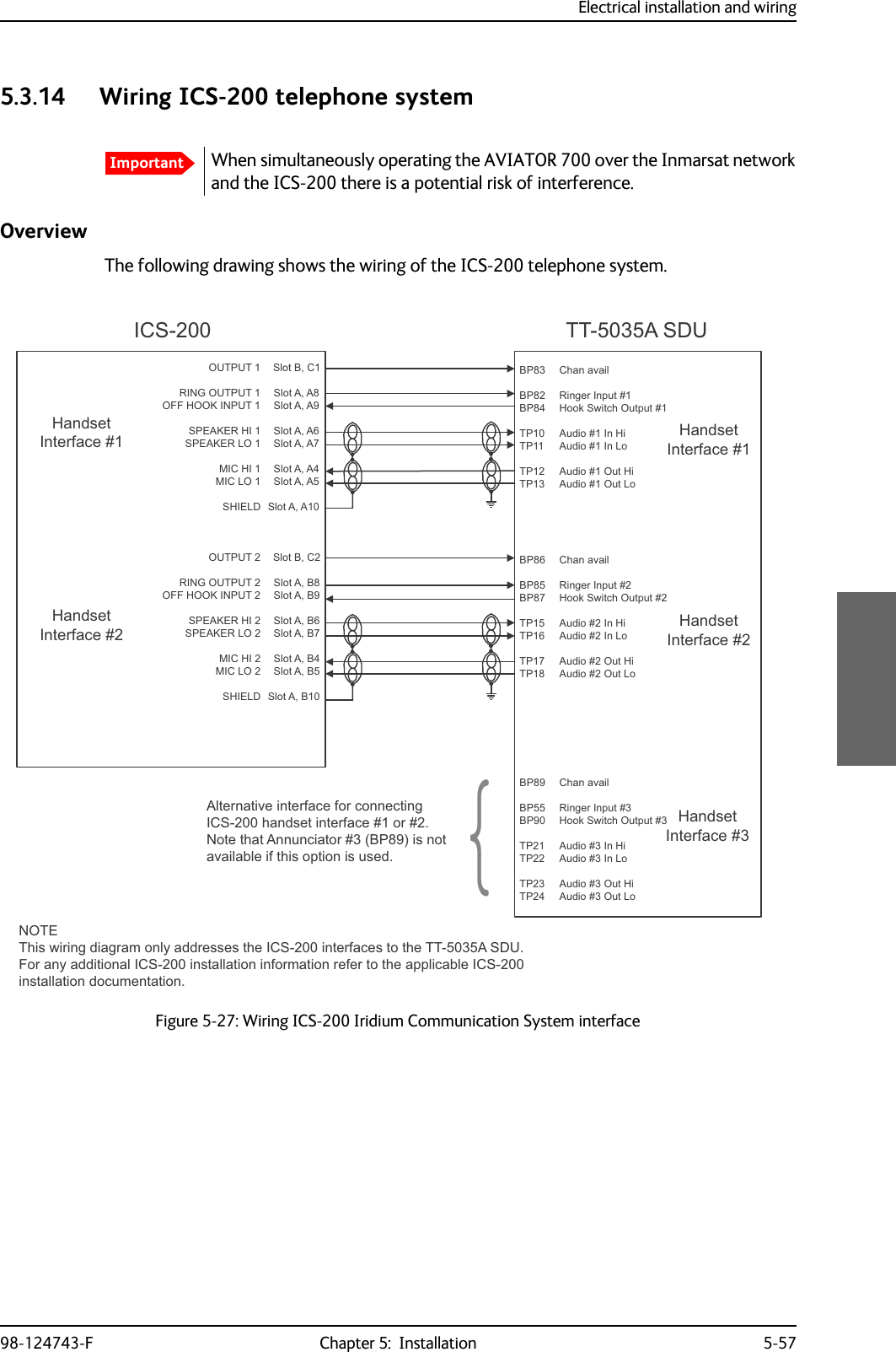
![Electrical installation and wiring98-124743-F Chapter 5: Installation 5-49Configuration of wired handset interfacesThe following drawing shows the possible combinations of devices connected to the handset interfaces.Figure 5-23: Handset interfaces, possible combinations of connected devices.77$6%83ULYDWH%UDQFK([FKDQJH3%;>@0D[LPXPWZR0DJQD6WDU$,8VPD\EHLQVWDOOHG7KHSUHIHUUHGLQVWDOODWLRQRI$,8LVWRWKHIRXUZLUH+DQGVHWLQWHUIDFHEXW$,8PD\DOWHUQDWLYHO\EHFRQQHFWHGWRWKHIRXUZLUH+DQGVHWLQWHUIDFHLQVWHDG77$6'83ULYDWH%UDQFK([FKDQJH3%;ZLUHDXGLR&RQWUROVLJQDOV77$77$+DQGVHW6\VWHPRU0DJQDVWDU>@$,8RU,ULGLXP,&6>@RU*+]&RUGOHVV3KRQH:+RU&RFNSLW9RLFH$06)RXUZLUH+DQGVHWLQWHUIDFHZLUHDXGLR&RQWUROVLJQDOV77$77$+DQGVHW6\VWHPRU0DJQDVWDU>@$,8RU,ULGLXP,&6>@RU*+]&RUGOHVV3KRQH:+RU&RFNSLW9RLFH$06)RXUZLUH+DQGVHWLQWHUIDFHZLUHDXGLR&RQWUROVLJQDOV77$77$+DQGVHW6\VWHPRU$OWHUQDWLYH0DJQDVWDU>@$,8RU,ULGLXP,&6>@RU*+]&RUGOHVV3KRQH:+)RXUZLUH+DQGVHWLQWHUIDFHZLUHDXGLR&RQWUROVLJQDOV77$77$+DQGVHW6\VWHP)RXUZLUH+DQGVHWLQWHUIDFHZLUH327677%77%FUDGOHKDQGVHWRU*+]&RUGOHVV3KRQH3276RU6LJPD3KRQHRU)$;RU0RGHP7ZRZLUH+DQGVHWLQWHUIDFHZLUH327677%77%FUDGOHKDQGVHWRU*+]&RUGOHVV3KRQH3276RU6LJPD3KRQHRU)$;RU0RGHP7ZRZLUH+DQGVHWLQWHUIDFH,6'1,6'13KRQHV,6'10RGHP,6'1LQWHUIDFHZLUH327677%77%FUDGOHKDQGVHWRU*+]&RUGOHVV3KRQH3276RU6LJPD3KRQHRU)$;RU0RGHP7ZRZLUH+DQGVHWLQWHUIDFHZLUH327677%77%FUDGOHKDQGVHWRU*+]&RUGOHVV3KRQH3276RU6LJPD3KRQHRU)$;RU0RGHP7ZRZLUH+DQGVHWLQWHUIDFH>@ 7ZR KDQGVHW LQWHUIDFHV IURP WKH ,&6 V\VWHP FDQ EH FRQQHFWHG WR](https://usermanual.wiki/Thrane-and-Thrane-A-S/AVIATOR700.Installation-Manual/User-Guide-4022295-Page-151.png)
![Electrical installation and wiring5-60 Chapter 5: Installation 98-124743-F5.3.15 Wiring 2.4GHz Cordless (4-wire) phoneOverviewThe following drawing shows the wiring of 2.4GHz Cordless 4-wire phones.Figure 5-28: Wiring 2.4GHz Cordless 4-wire phonesNoteThe power for the 2.4GHz Cordless base unit must be supplied from an external power supply. See the 2.4GHz Cordless manual for details.*+]&RUGOHVV%DVH8QLW7[/R%3%37373737377$6'8%3%373737373%3%3737373737[+L+DQGVHW,QWHUIDFH*+]&RUGOHVV%DVH8QLW*+]&RUGOHVV%DVH8QLW---5[+L5[/R5LQJLQ+RRN6ZLWFK7[/R7[+L5[+L5[/R5LQJLQ+RRN6ZLWFK7[/R7[+L5[+L5[/R5LQJLQ+RRN6ZLWFK:+0DJQD6WDU+RRN6ZLWFK:+0DJQD6WDU5LQJHU2XWSXW$+DQGVHW$XGLR2XW+L+DQGVHW$XGLR2XW/R+DQGVHW$XGLR,Q+L+DQGVHW$XGLR,Q/R:+0DJQD6WDU+RRN6ZLWFK:+0DJQD6WDU5LQJHU2XWSXW$+DQGVHW$XGLR2XW+L+DQGVHW$XGLR2XW/R+DQGVHW$XGLR,Q+L+DQGVHW$XGLR,Q/R+DQGVHW$XGLR2XW+L+DQGVHW$XGLR2XW/R+DQGVHW$XGLR,Q+L+DQGVHW$XGLR,Q/R:+0DJQD6WDU+RRN6ZLWFK:+0DJQD6WDU5LQJHU2XWSXW$+DQGVHW,QWHUIDFH+DQGVHW,QWHUIDFH](https://usermanual.wiki/Thrane-and-Thrane-A-S/AVIATOR700.Installation-Manual/User-Guide-4022295-Page-162.png)
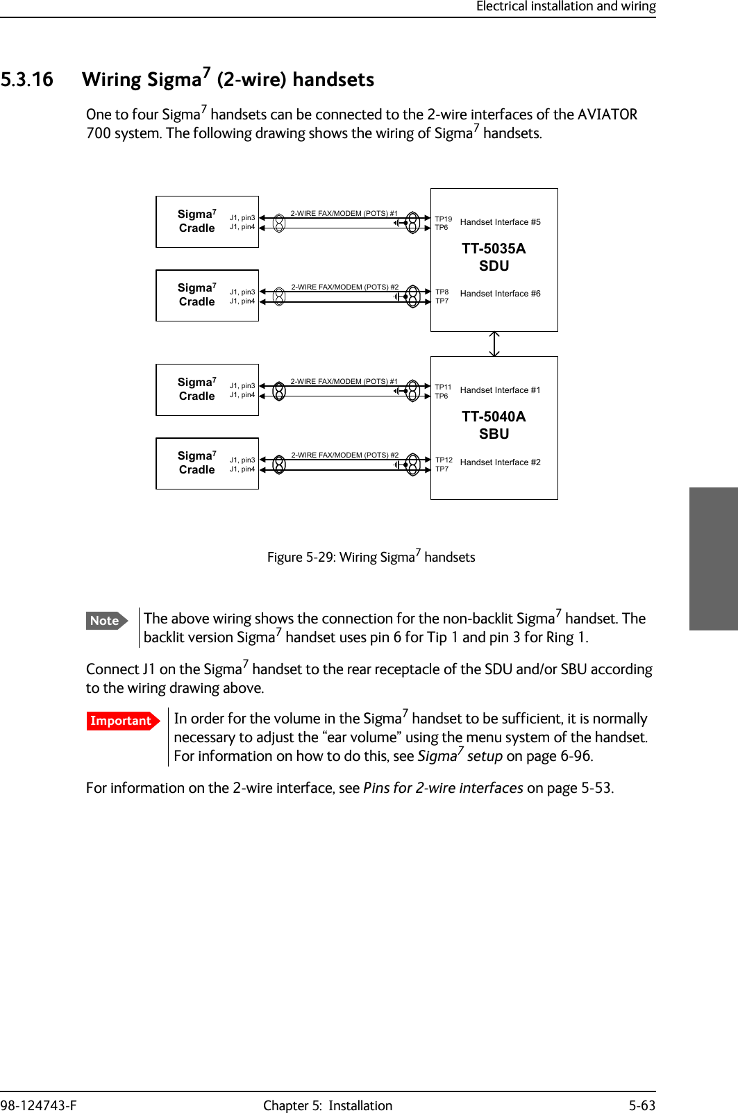
![Electrical installation and wiring5-64 Chapter 5: Installation 98-124743-F5.3.17 Wiring ICG DECT Cordless Handset (2-wire) phoneOne to four ICG DECT Cordless Handset phones can be connected to the 2-wire interfaces of the AVIATOR 700 system. The following drawing shows the wiring of ICG DECT Cordless Handset 2-wire phones.Connect J2 on the base station of the ICG DECT Cordless Handset phone to the rear receptacle of the SDU and/or SBU according to the wiring drawing above. The base station is supplied together with the handset and cradle.In order for the ICG DECT Cordless Handset phone to work properly, it is normally necessary to make a few initial adjustments of the handset. For information on how to do this, see ICG DECT Cordless Handset setup on page 6-96.For information on the 2-wire interface, see Pins for 2-wire interfaces on page 5-53.Figure 5-30: Wiring 2.4GHz Cordless handsetsImportant:,5()$;02'(03276*+]&RUGOHVV%DVH8QLW:,5()$;02'(0327677$6'873737373-SLQ-SLQ-SLQ*+]&RUGOHVV%DVH8QLW-SLQ-SLQ-SLQ+DQGVHW,QWHUIDFH+DQGVHW,QWHUIDFH:,5()$;02'(03276*+]&RUGOHVV%DVH8QLW:,5()$;02'(0327677$6%873737373-SLQ-SLQ-SLQ*+]&RUGOHVV%DVH8QLW-SLQ-SLQ-SLQ+DQGVHW,QWHUIDFH+DQGVHW,QWHUIDFH](https://usermanual.wiki/Thrane-and-Thrane-A-S/AVIATOR700.Installation-Manual/User-Guide-4022295-Page-166.png)
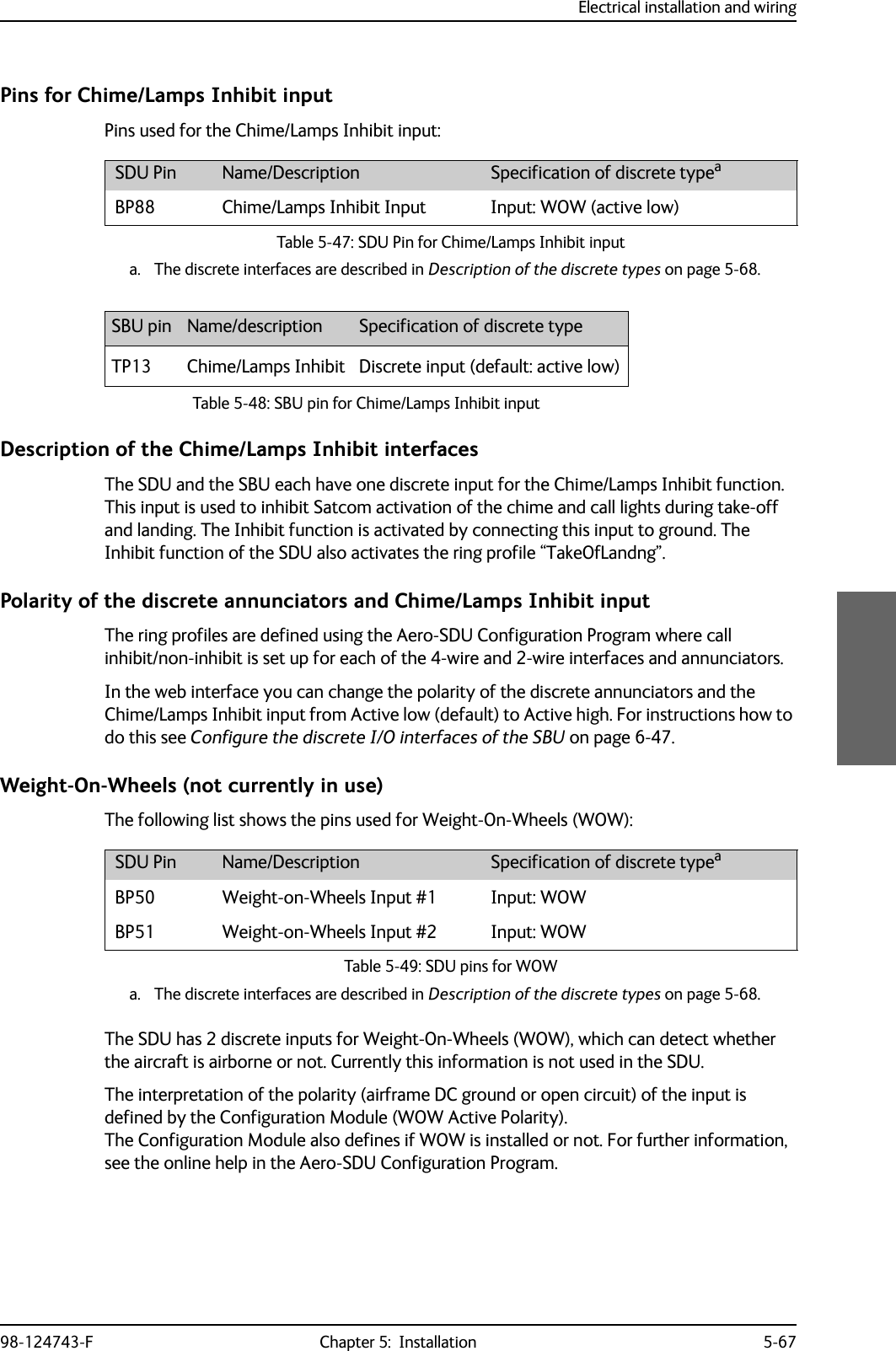
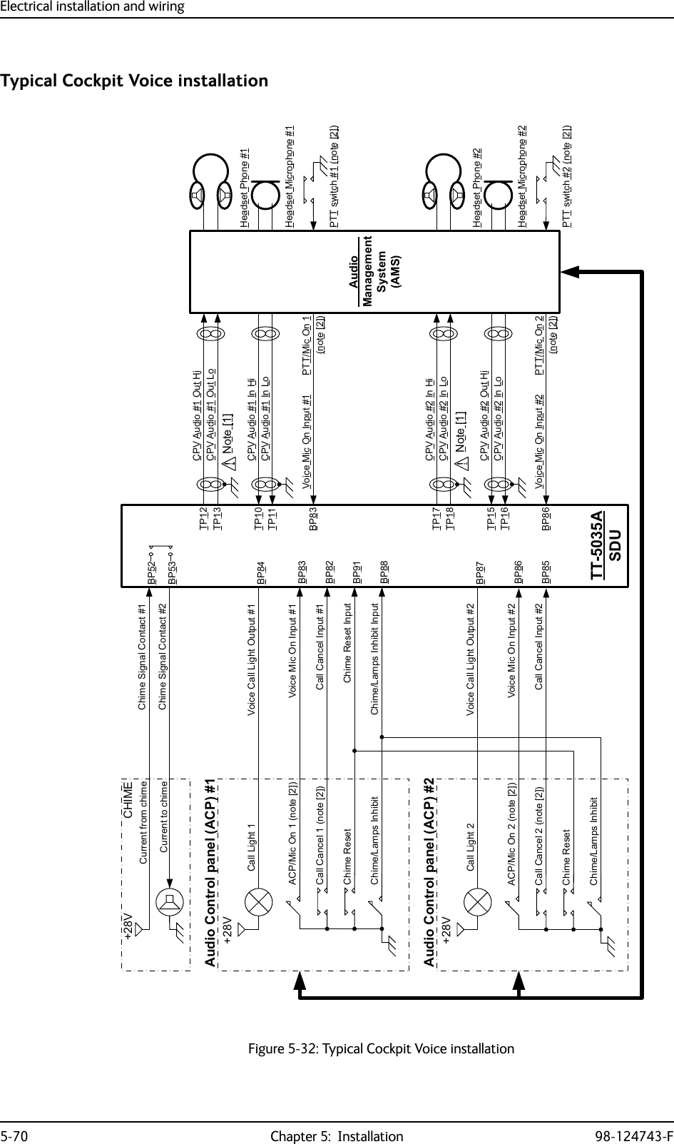
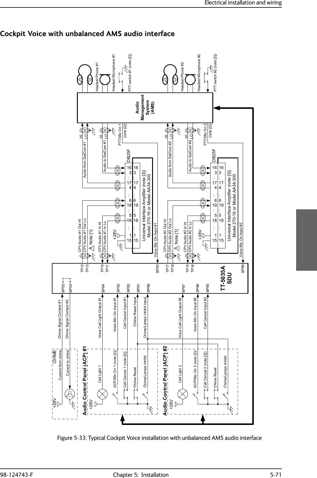
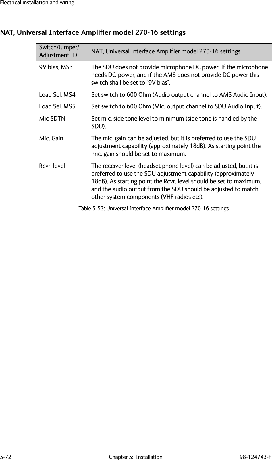
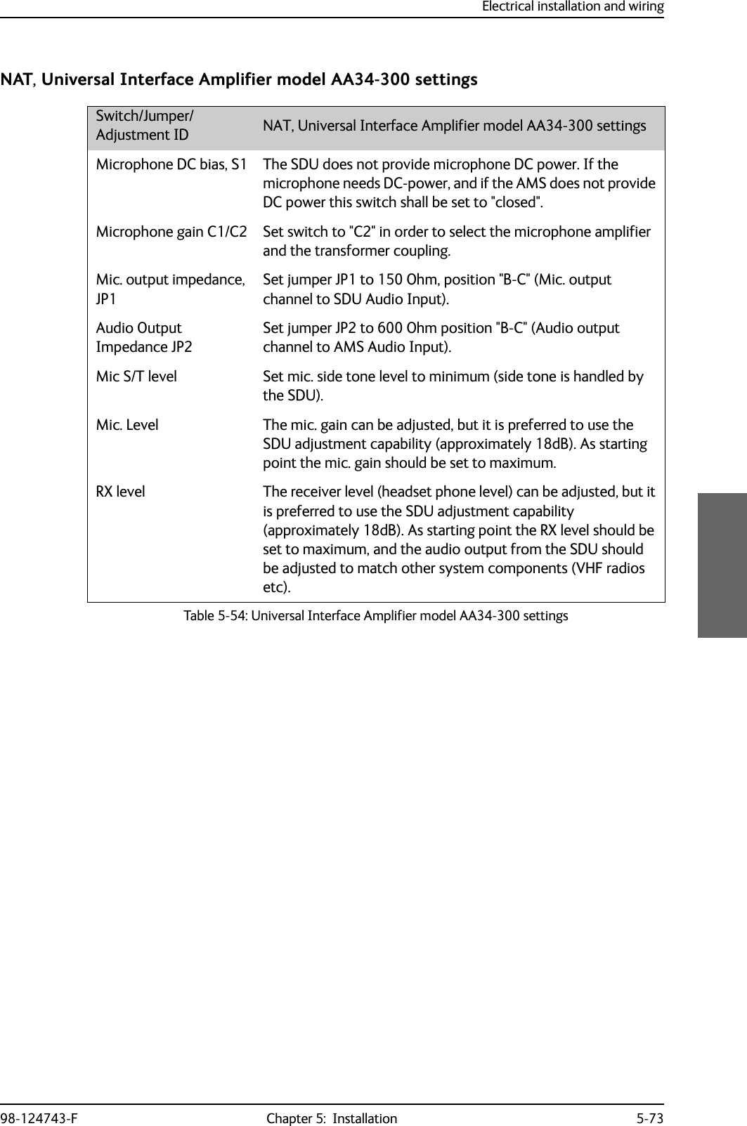
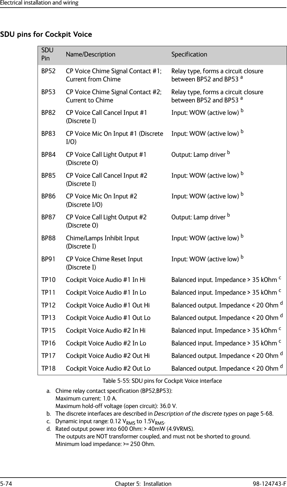
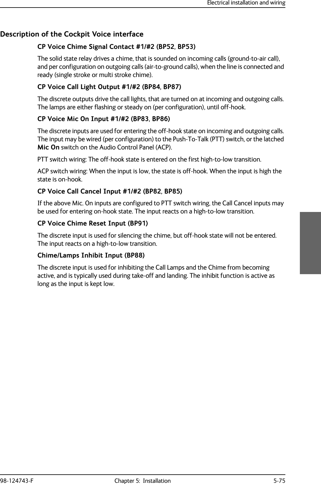
![Electrical installation and wiring98-124743-F Chapter 5: Installation 5-695.3.19 Wiring Cockpit Voice interfaceIntroductionThe Cockpit Voice interface must be wired to the Audio Management System (AMS) and an Audio Control Panel (ACP) or similar. Figure 5-32: shows a typical Cockpit Voice installation. Pay attention to the drawing notes:NOTES:[1]The balanced audio outputs from the SDU (TP10, TP11, TP17 and TP18) are not transformer coupled. Do not connect HI or LO output to ground.[2]Off-hook is signalled in 3 ways (per configuration). Use either• Push-To-Talk (PTT) switch•Latched Audio Control Panel switch•MCDU line switch[3]If the AMS has unbalanced audio inputs or outputs, transformers should be inserted in the audio lines, to convert the balanced signals to unbalanced and vice versa. Figure 5-33: shows a typical installation for an AMS with unbalanced audio inputs/ outputs. The Universal Interface Amplifier model 270-16 from Northern Airborne Technology (NAT) has built-in transformers. Alternatively the model AA34-300 may be used (with the same I/O pin configuration). The settings of the Universal Interface Amplifier are listed in Table 5-53 on page 5-72 and Table 5-54 on page 5-73. Northern Airborne Technology (NAT) part numbersPart name Part numberUniversal Interface Amplifier Model 270-16Universal Radio Interface Model AA34-300Table 5-52: Northern Airborne Technology (NAT) part numbers.](https://usermanual.wiki/Thrane-and-Thrane-A-S/AVIATOR700.Installation-Manual/User-Guide-4022295-Page-171.png)
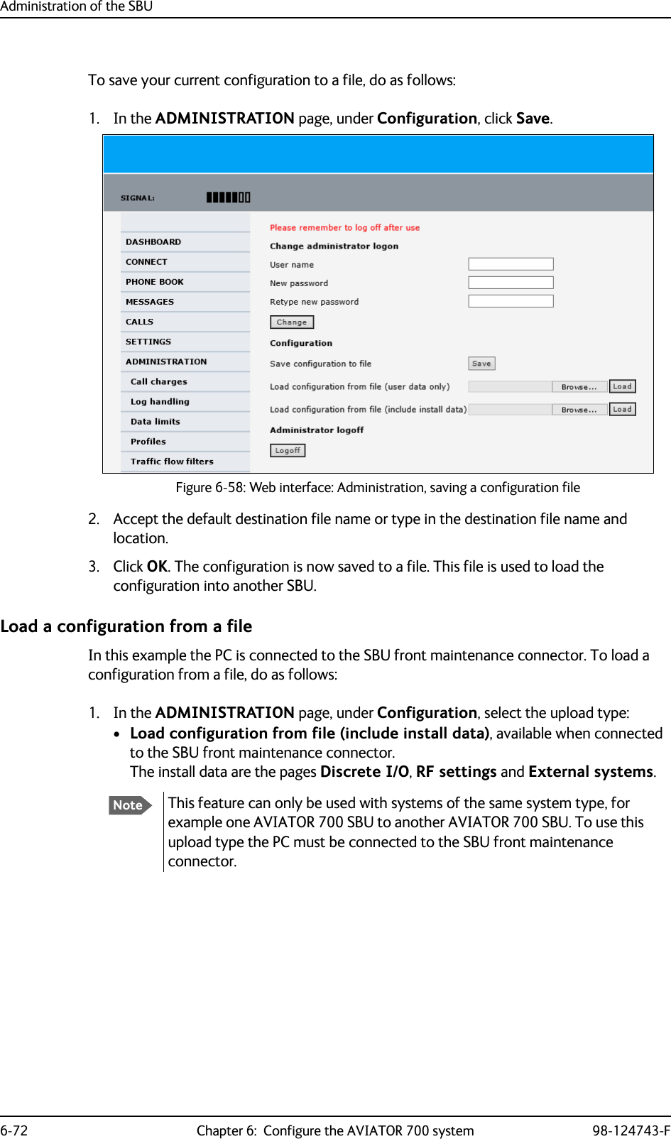
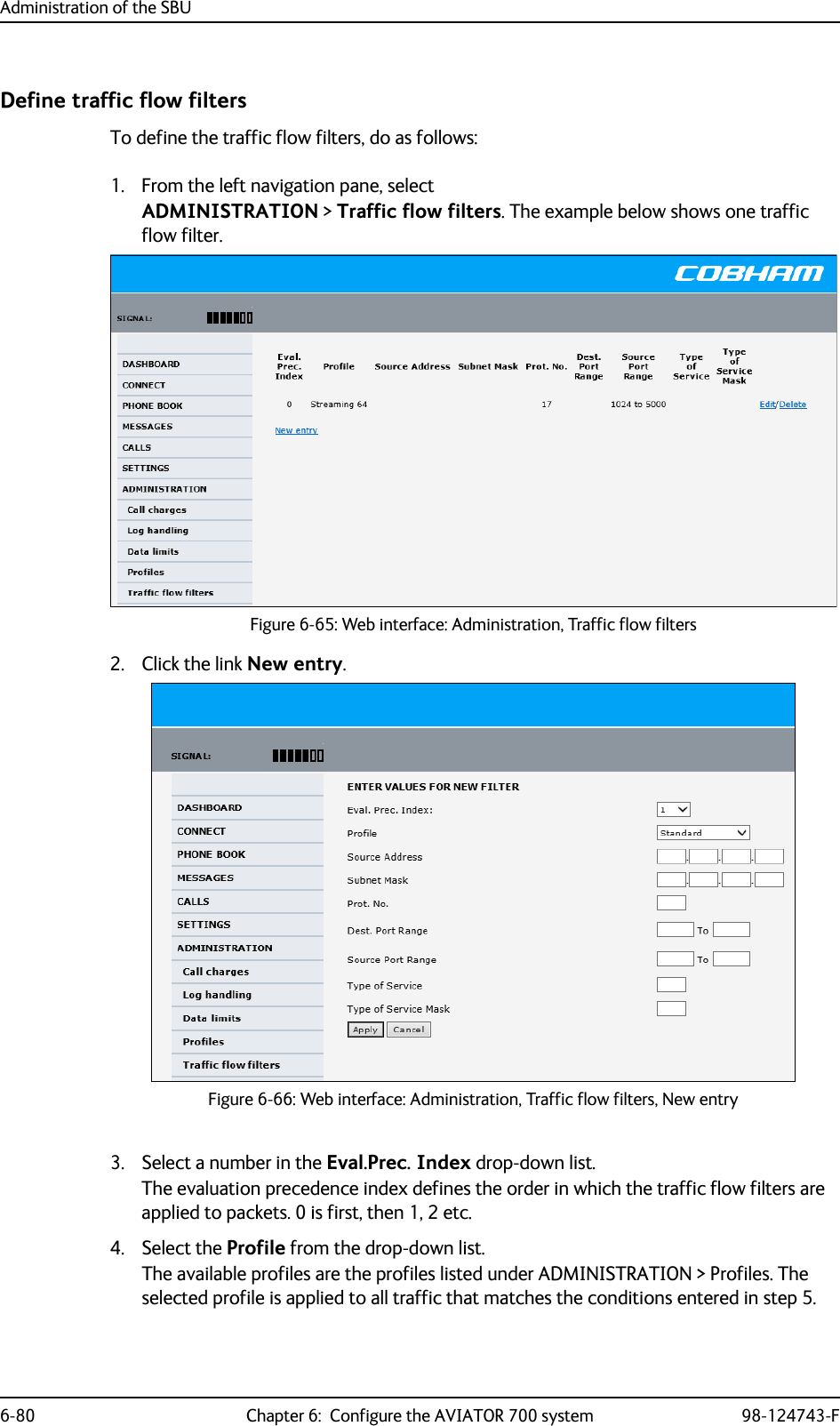
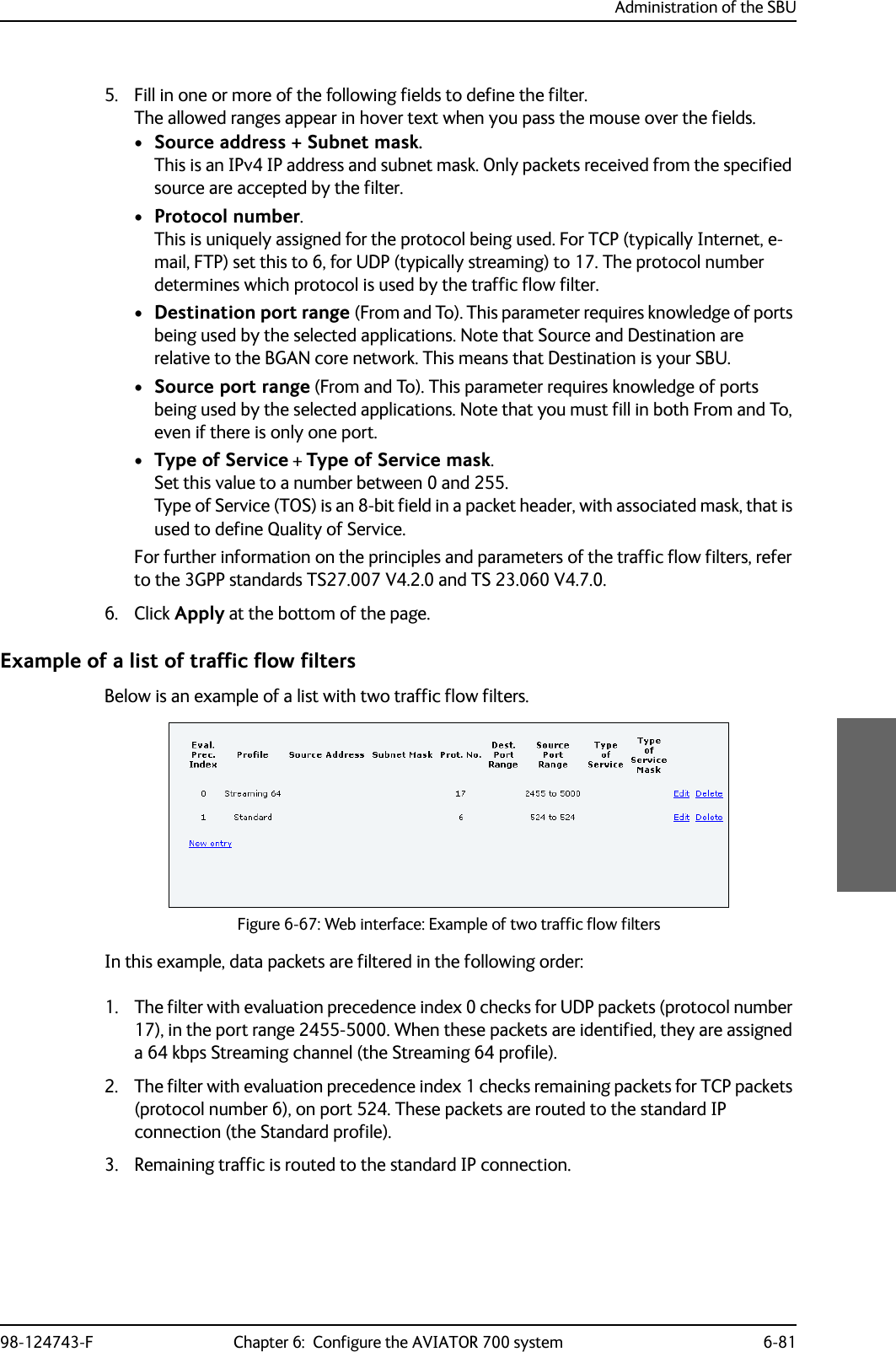
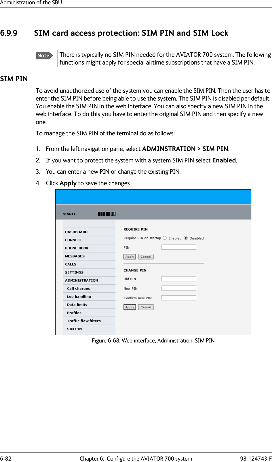
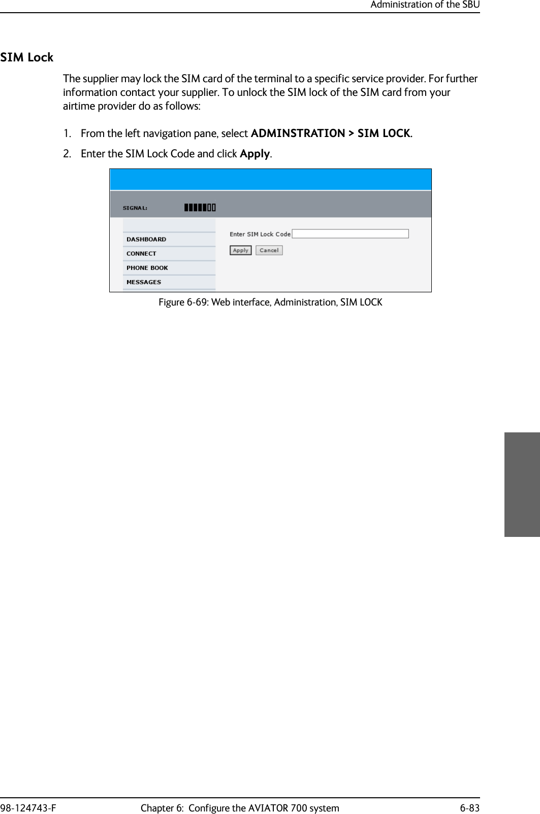
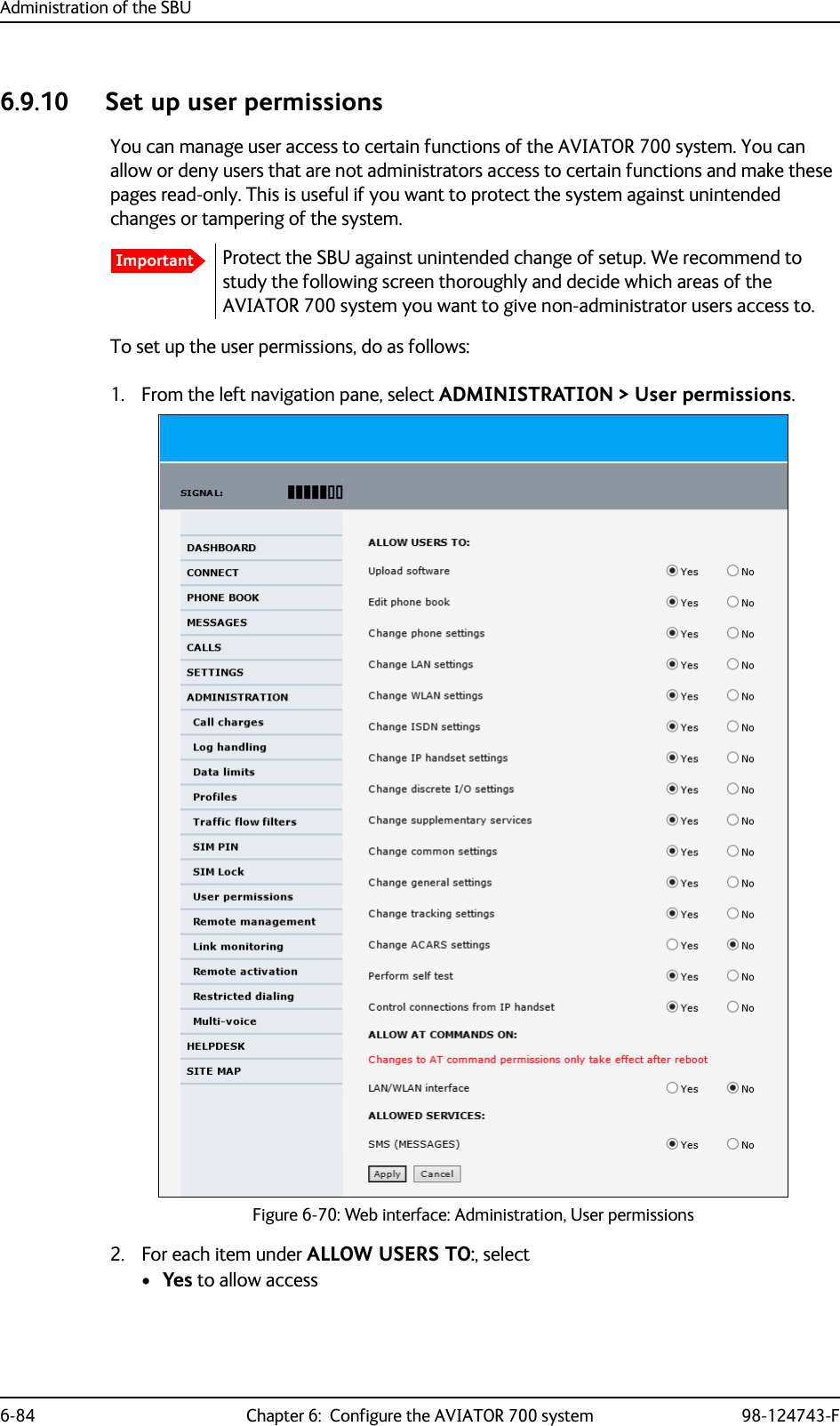
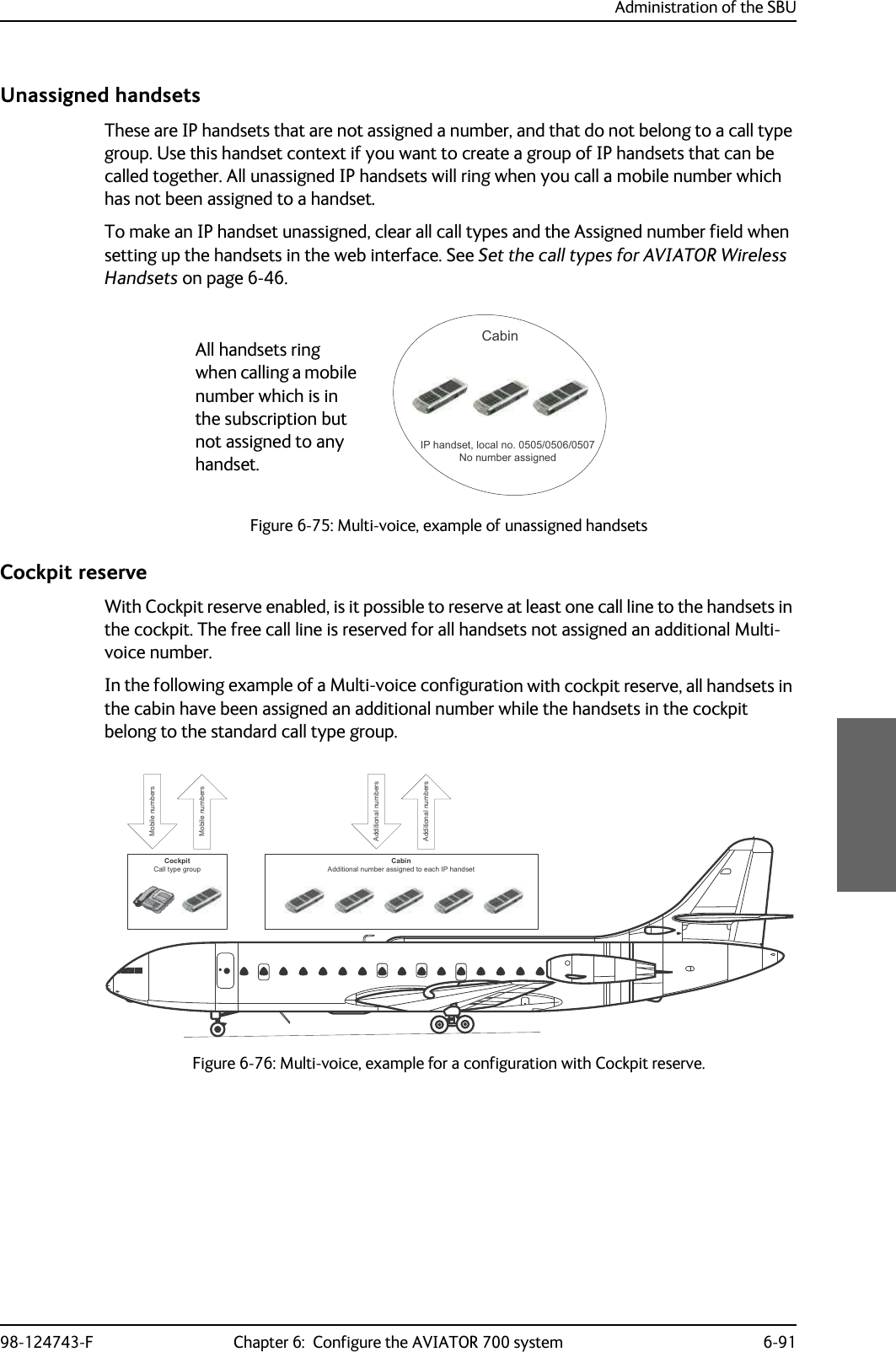
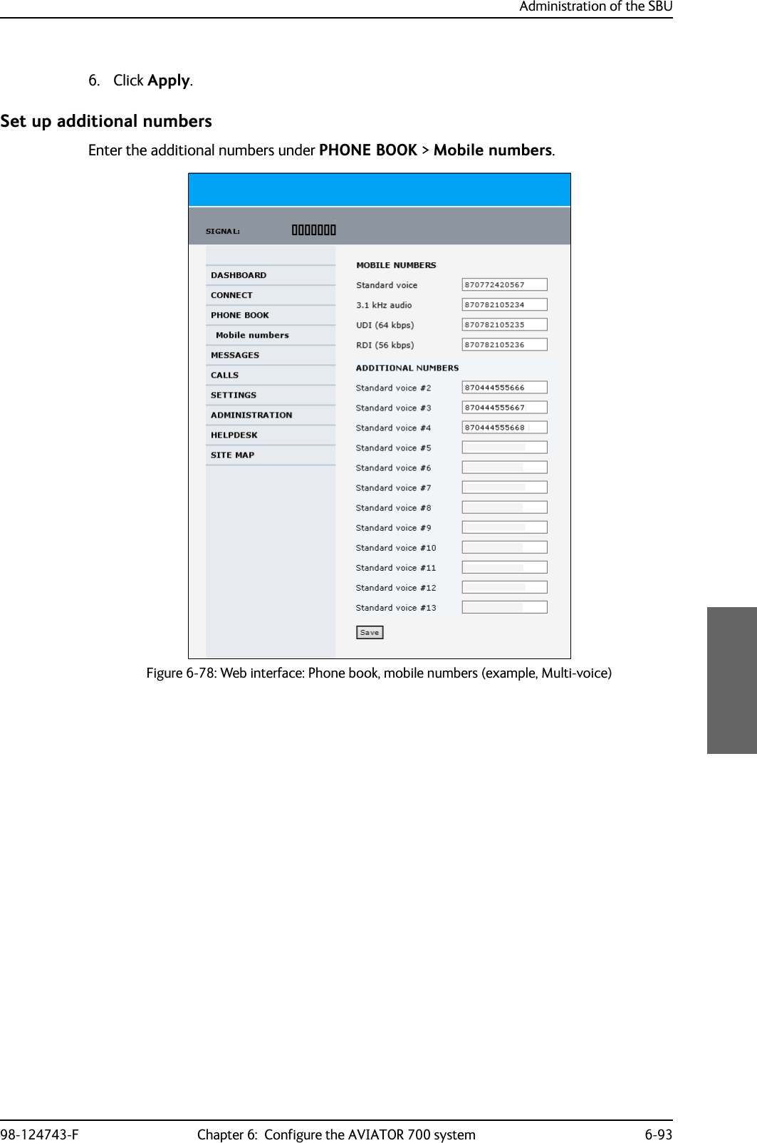
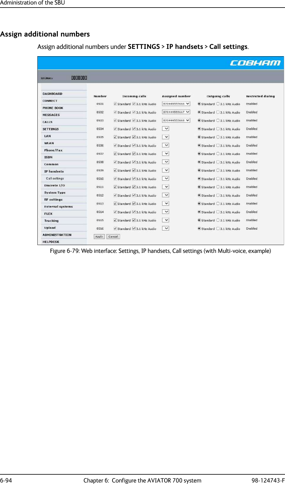
![Administration of the SBU6-90 Chapter 6: Configure the AVIATOR 700 system 98-124743-FDirectly assigned handsetsThe mobile numbers are assigned to individual handsets. Only the assigned handset will ring when the associated number is called.For information on how to assign a number to a handset, see the pages SETTINGS > Phone/Fax, SETTINGS > ISDN or SETTINGS > IP handsets in the web interface.Note that you can also assign the call type numbers directly (in the example above, the Standard Voice number is assigned to IP handset number 0501). If you do so, be aware that only the assigned handset can receive a call to this number. The handset connected to the Phone port 1 and the IP handset no. 0502 are each assigned an additional number.Figure 6-73: Multi-voice, call type groups (example)&DOO7\SH 6WDQGDUG &DOO7\SH N+]6WDQGDUG9RLFHQXPEHU,6'13RUW3KRQH)D[3RUW,6'13RUW3KRQH)D[3RUWN+]$XGLRQXPEHU[NoteTo use this feature you must have additional numbers in your airtime subscription and enable the use of additional numbers in the web interface. Then you can assign the numbers to individual handsets. For details on additional numbers, see Additional numbers for Multi-voice on page 6-89.Figure 6-74: Multi-voice, example of directly assigned handsets (example),3KDQGVHWORFDOQR $GGLWLRQDOQXPEHU&DELQ,3KDQGVHWORFDOQR 6WDQGDUG9RLFHQXPEHU3DQWU\3KRQH)D[SRUW $GGLWLRQDOQXPEHU&RFNSLW](https://usermanual.wiki/Thrane-and-Thrane-A-S/AVIATOR700.Installation-Manual/User-Guide-4022295-Page-280.png)
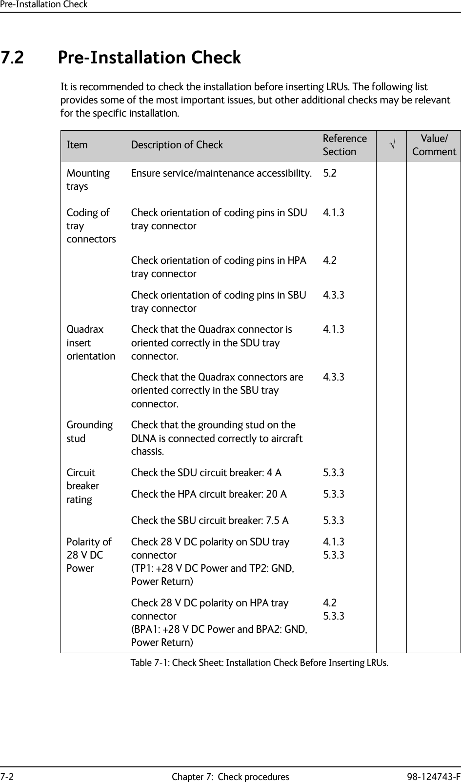
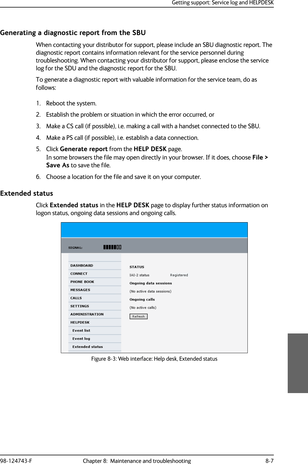
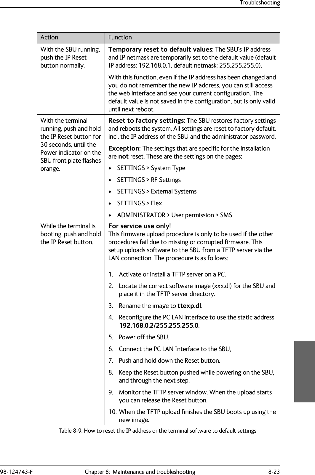

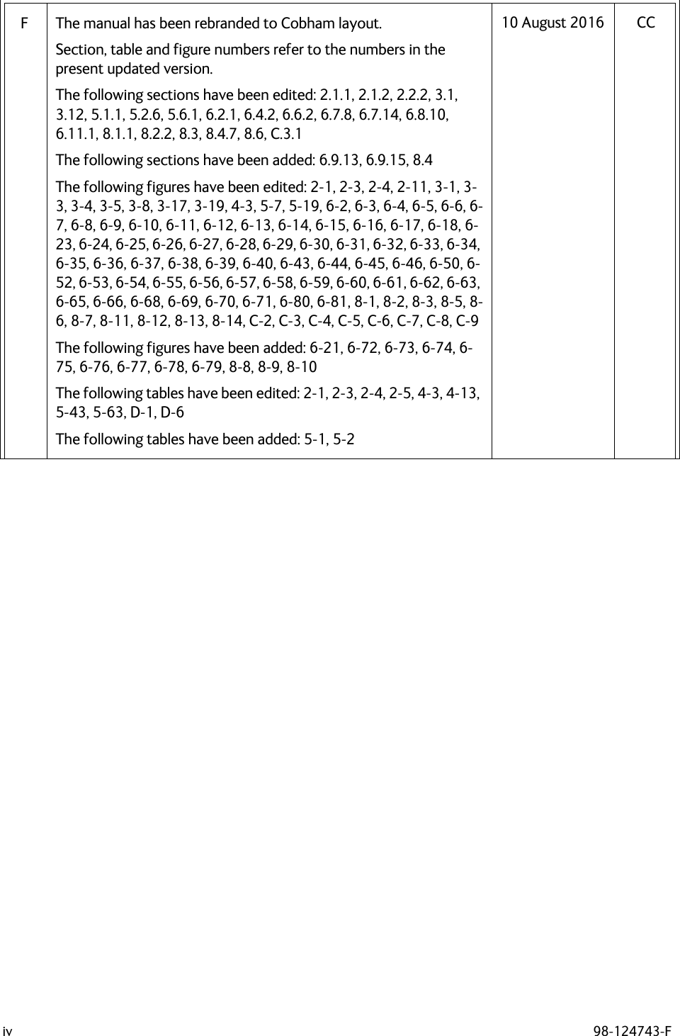
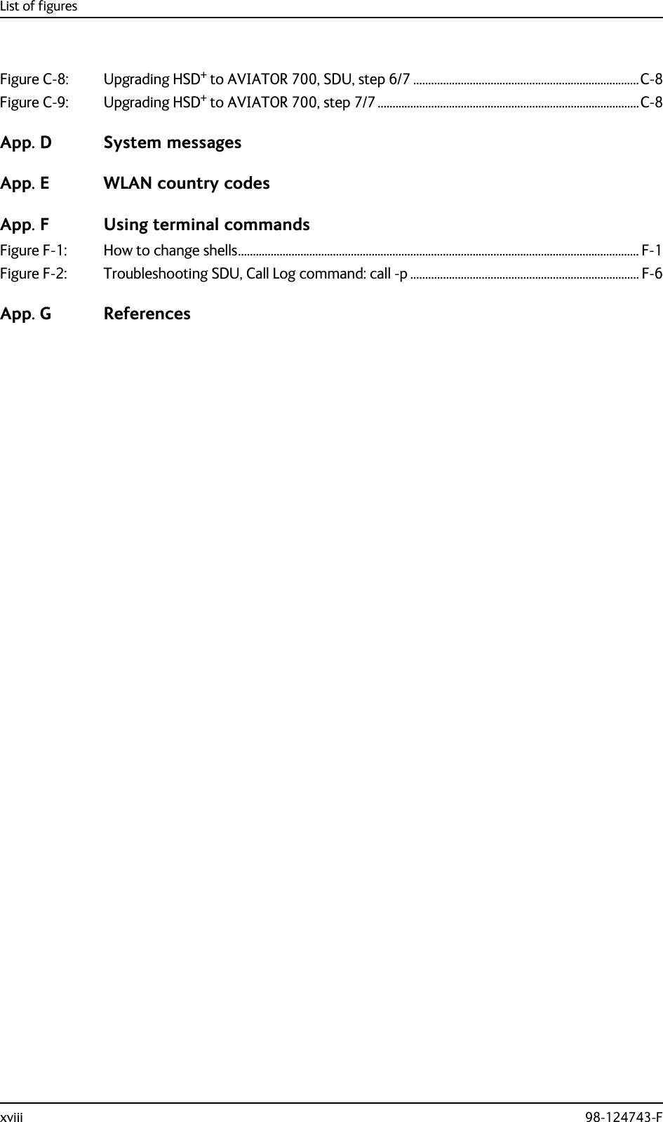
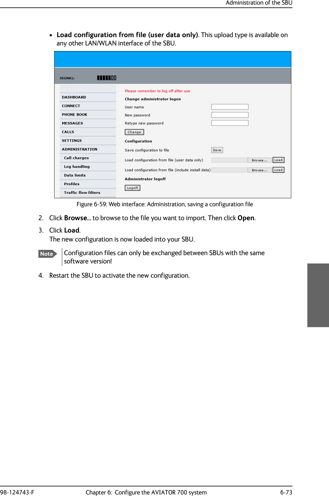
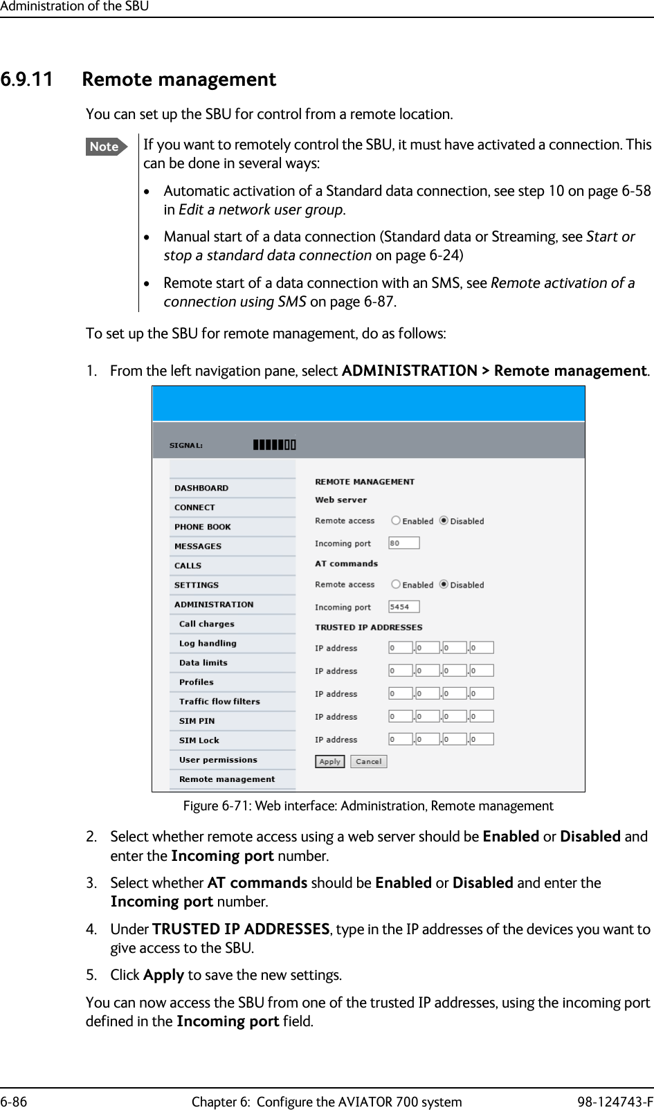
![Troubleshooting8-28 Chapter 8: Maintenance and troubleshooting 98-124743-FCheck of Ethernet, ISDN and handsetsAfter checking the LEDs, the user functions should be checked.The below flow chart shows the initial check of Ethernet, ISDN and handsets.Figure 8-16: Initial check of Ethernet, fax, 4-Wire Handsets and ISDN&RQWLQXHWR&KHFNRI)$;&KHFN3&KDVFRUUHFW,3DGGUHVV3&FDQSLQJ6%8GHIDXOWJZ<HV1R1R(WKHUQHWZRUNLQJ"ZLUHKDQGVHWVZRUNLQJ"<HV$FFHVVWR6%8:HE"<HV1R (WKHUQHW/LQN"1R<HV&KHFN:LULQJEHWZHHQ6%8DQG3&3&HWKHUQHWVSHHGFRUUHFW&KHFNRQ6%8$31$FFHVV3RLQW1DPH3URILOHVDQGIORZILOWHUV6LJQDOVWUHQJWK!G%+]DWFDOO6,0DFWLYDWHGIRUXVHGVHUYLFH/RJIRUHUURUFRGHV1R,6'1ZRUNLQJ" 'LDOWRQH"&KHFN6%8VLJQDOVWUHQJWK6HUYLFHDQGFDOOURXWLQJ/RJIRUHUURU<HV1R&KHFN,QWHUIDFHHQDEOHG([WHUQDOSRZHURQGHYLFH:LULQJEHWZHHQ6%873DQG,6'1GHYLFHZLUHKDQGVHWVZRUNLQJ",QWHUQDOFDOO2.1R$LUWR*1'2.*1'WRDLU2.1R1R&KHFN+DQGVHWSOXJJHGFRUUHFWO\LQWRFUDGOH:LULQJIURPFUDGOHWR6'8+DQGVHWFRQILJXUDWLRQLQ$HUR6'8&3<HV<HV&KHFN&DOOUHOHDVHFRGHGLVSOD\HGLQWKHKDQGVHWZKLOHPDNLQJDFDOO7URXEOHVKRRWDFFRUGLQJO\&KHFN'LDOHGQXPEHULVFRUUHFWDVVKRZQRQDFWLYDWLRQIRUP+DQGVHWLVQRWLQKLELWHGE\IODSVRUVODWV5RXWLQJLVFRUUHFWDVN\RXUVHUYLFHSURYLGHU'LDOWRQH" 1R&KHFN+DQGVHWSOXJJHGFRUUHFWO\LQWRFUDGOH:LULQJIURPFUDGOHWR6'86%81R<HV &KHFN(UURUWRQHLQKDQGVHWZKHQGLDOLQJ&DOOUHOHDVHFRGHLQFDOOORJ'DWD$),6$&$56&08ZRUNLQJ"1R 6\VWHPUHDG\1R&KHFN&RQQHFWLRQEHWZHHQ6'8%3DQG&08&RQILJXUDWLRQLQ$HUR6'8&3&08$&$56PDUNHG&RQQHFWHGDQGFRUUHFWVSHHGVHOHFWHG<HV&KHFN,&$2QXPEHULVDFWLYDWHGIRU'DWD<HV<HV<HV<HV](https://usermanual.wiki/Thrane-and-Thrane-A-S/AVIATOR700.Installation-Manual/User-Guide-4022295-Page-328.png)
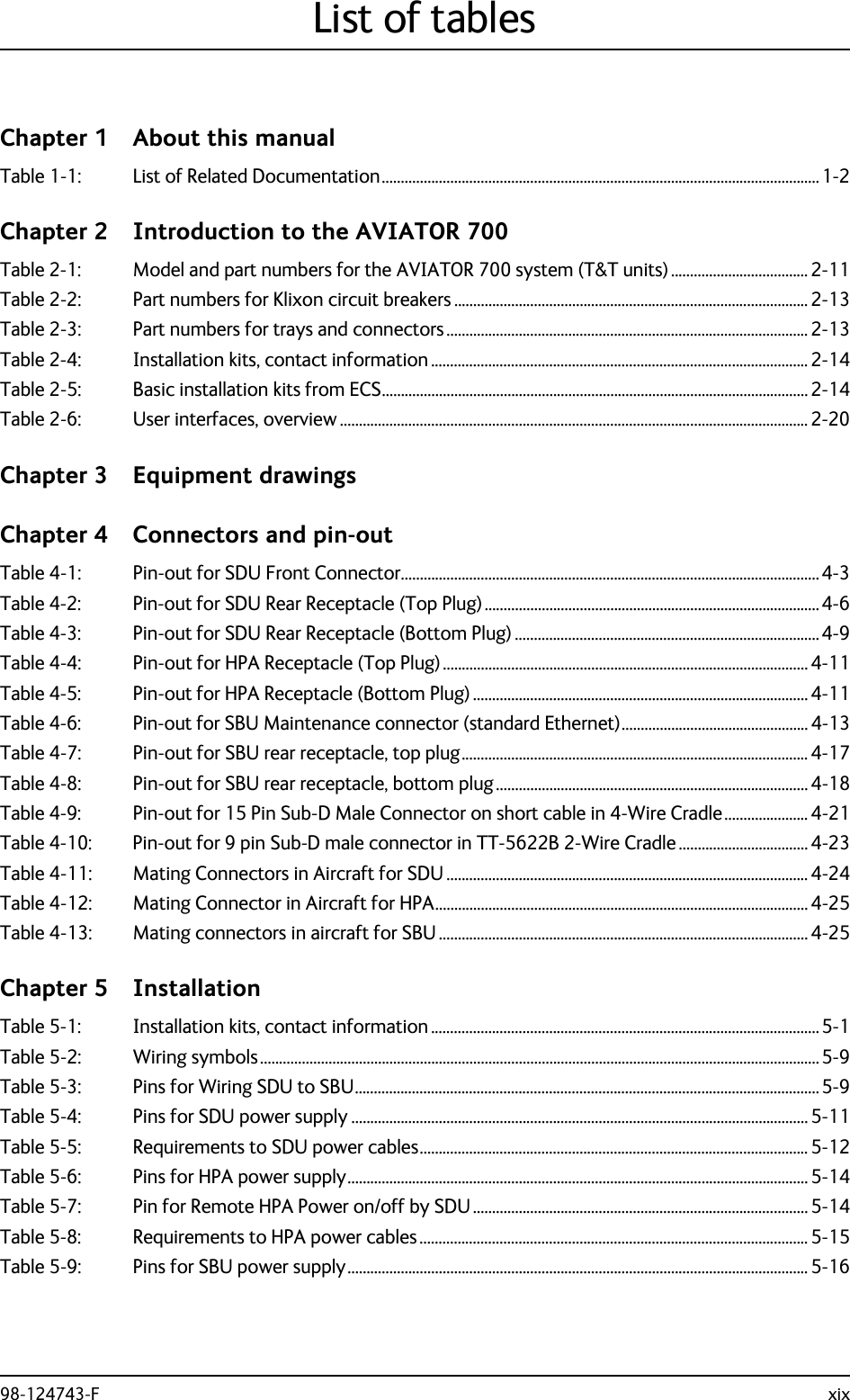
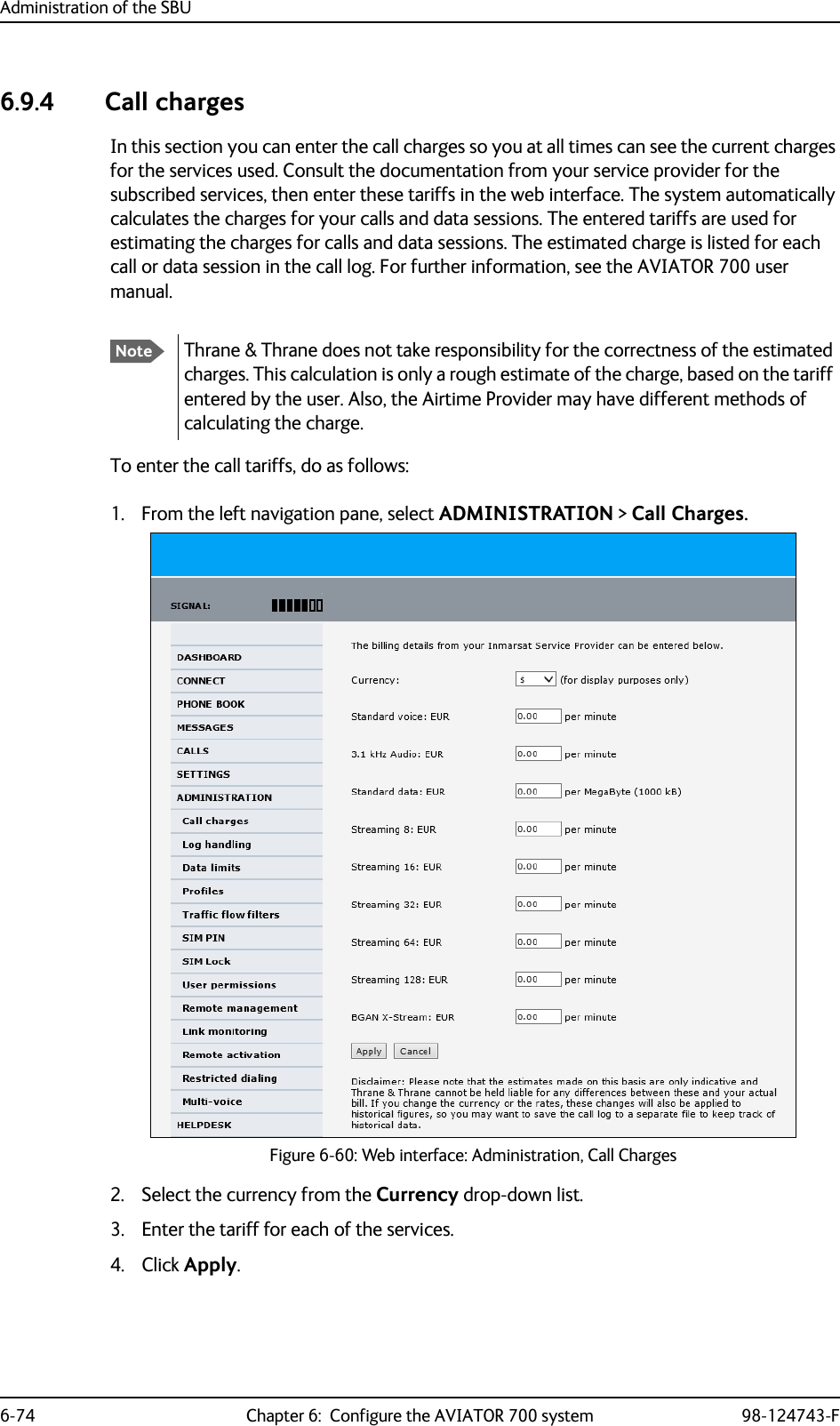
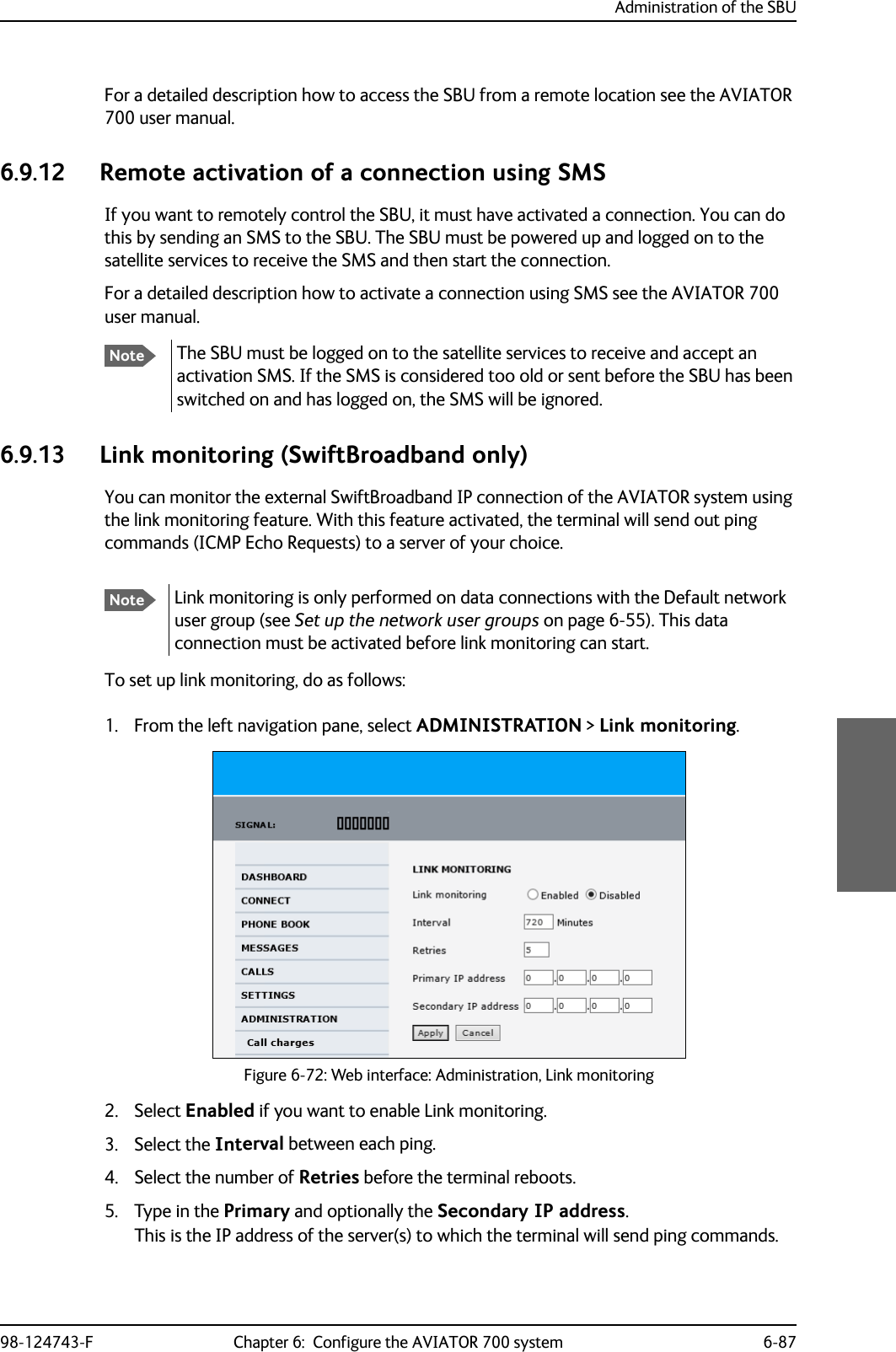
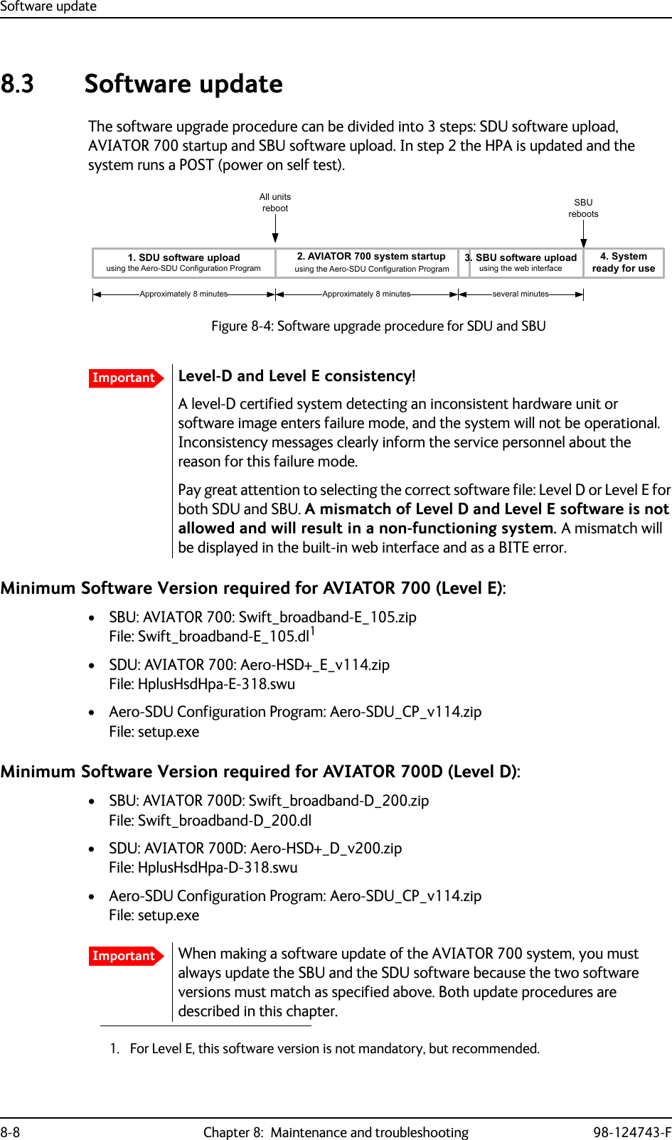
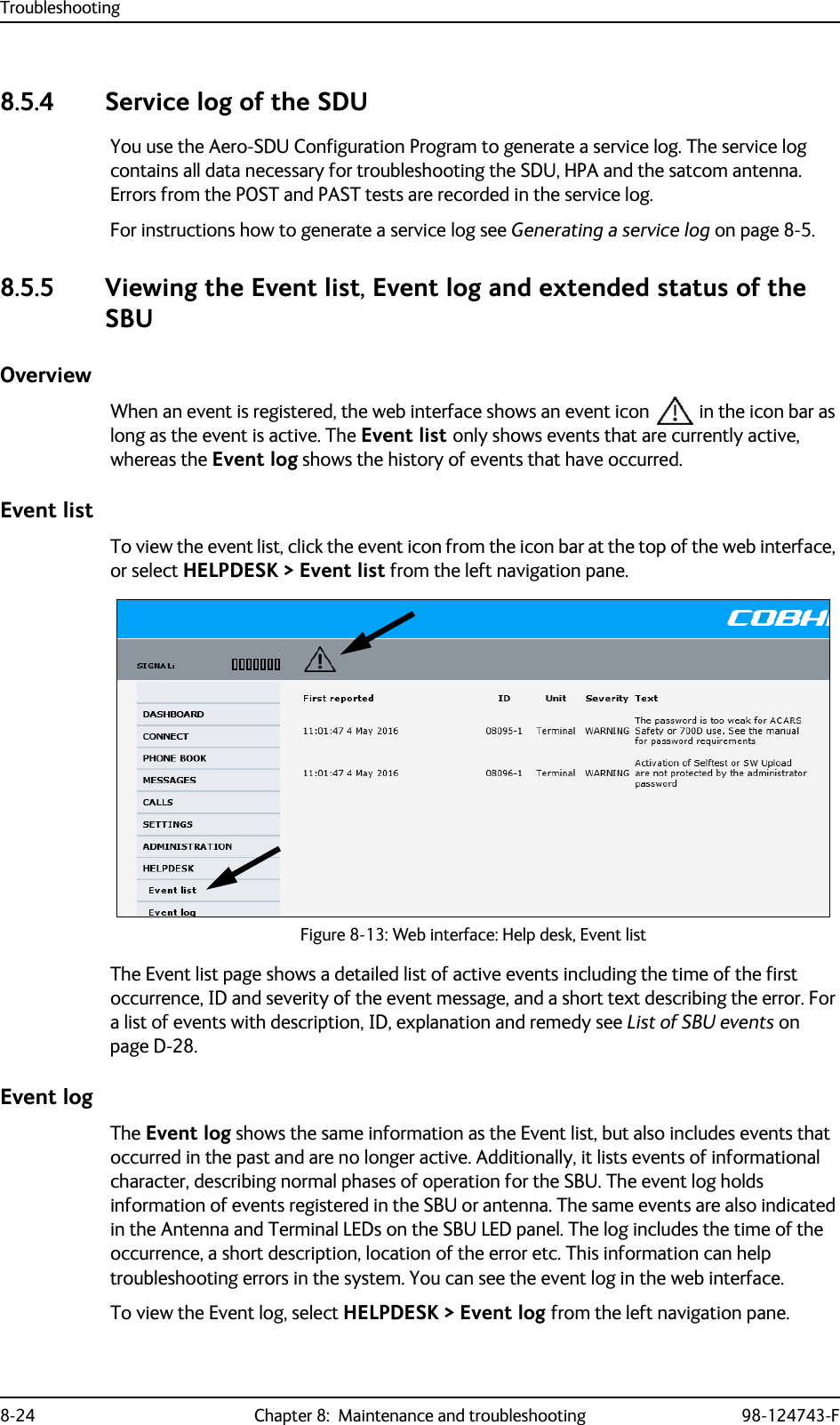
![Troubleshooting98-124743-F Chapter 8: Maintenance and troubleshooting 8-29Check of faxThe below flow chart shows the initial check of the fax interfaces.Figure 8-17: Initial check of Fax&KHFN2.<HV1R1R&KHFN&RQQHFWLRQIURPID[/LQHWR6'8SRUW73RU733RUWFRQILJXUHGDV´)D[´LQ$HUR6'8&3&KHFN&RQQHFWLRQWRFRUUHFWSRUWRQ6'8E\GLDOLQJRUIURPDKDQGVHW5LQJ3URILOHVFRUUHFWO\VHWXS6HUYLFH3URYLGHUKDVV\VWHPVHWXSIRU)$;RQ+DQGRQFRUUHFWSRUWVDPHDVDERYH&KHFN7KHID[PDFKLQHLVVHWIRURYHUVHDVPRGH8VHDVSUHIL[.+]DXGLRVHOHFWHGDVRXWJRLQJVHUYLFH&KHFN7KHID[PDFKLQHLVVHWIRURYHUVHDVPRGH7KHID[LVVHWWRSLFNXSDIWHUWZRRUOHVVULQJV<HV 1R1R<HV1R<HV1R<HV)D[ZRUNLQJ" )D[RQ+" 'LDOWRQH"5LQJLQJ")D[RQ6%8"6HQGLQJ2.$LUWR*1'5HFHLYH2.*1'WR$LU&KHFN7KHID[PDFKLQHLVVHWIRURYHUVHDVPRGH8VHDVSUHIL[)D[VWDUWXSWUDQVPLWVSHHGELWVUHFRPPHQGHG&KHFN7KHID[PDFKLQHLVVHWIRURYHUVHDVPRGH7KHID[LVVHWWRSLFNXSDIWHUWZRRUOHVVULQJV7KHID[LVLQ)$;PRGH<HV1R1R6HQGLQJ2.$LUWR*1'5HFHLYH2.*1'WR$LU<HV&KHFN3RUWVLQWHUIDFHHQDEOHW&RQQHFWLRQIURPID[/LQHWR6%873RU73&KHFN6HUYLFH3URYLGHUKDVV\VWHPVHWXSIRU)$;RQ6ZLIW%URDGEDQG1R1R<HV'LDOWRQH"5LQJLQJ"<HV<HV](https://usermanual.wiki/Thrane-and-Thrane-A-S/AVIATOR700.Installation-Manual/User-Guide-4022295-Page-329.png)

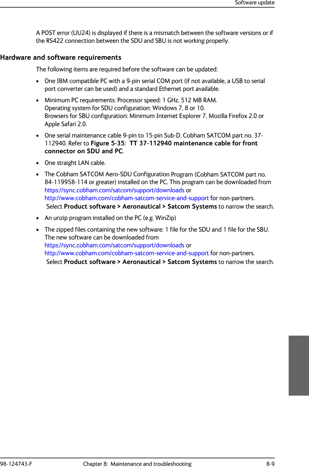
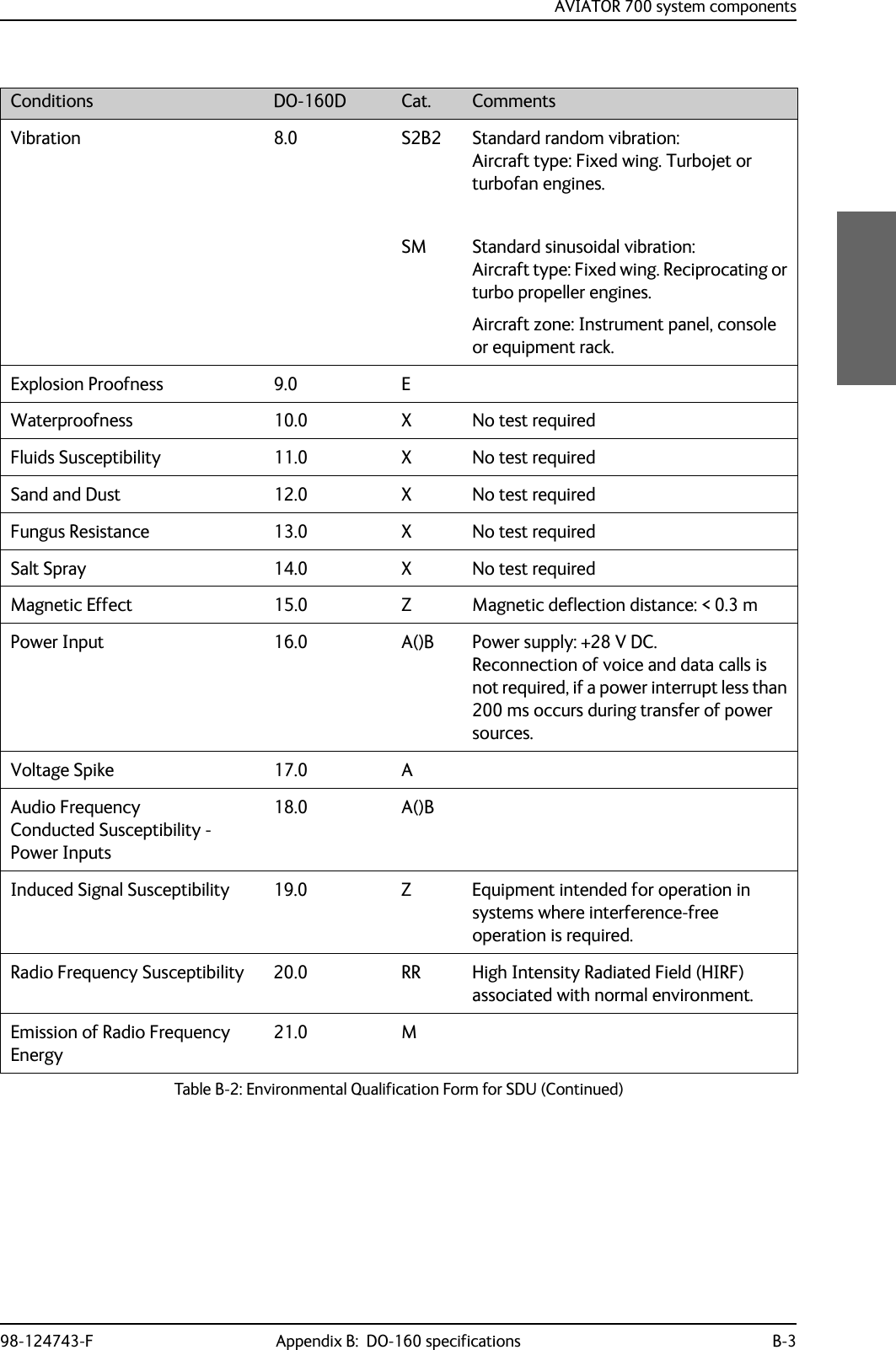
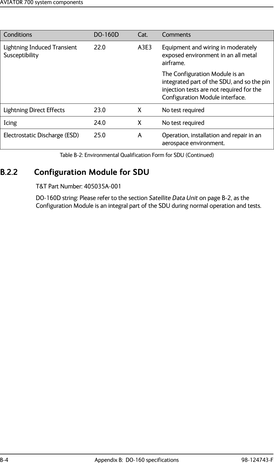
![AVIATOR 700 system componentsB-2 Appendix B: DO-160 specifications 98-124743-FB.2 AVIATOR 700 system componentsB.2.1 Satellite Data Unit T&T Part Number: 405035A (AVIATOR 700) or 405035A-THD (AVIATOR 700D)DO-160D string: [(A1)(F1)X]CAB[(S2B2)(SM)]EXXXXXZ[A()B]A[A()B]Z[RR]M[A3E3]XXARTCA/DO-160D Change NumbersChange Number Date of Issue Title SectionChange No. 1 Dec. 14, 2000 VibrationRadio Frequency Susceptibility8.020.0Change No. 2 June 12, 2001 Power InputAudio Frequency Conducted Susceptibility - Power Inputs16.018.0Table B-1: RTCA/DO-160D Change Numbers, SDUConditions DO-160D Cat. CommentsTemperature and Altitude 4.0 A1 and F1Installation in controlled temperature locations and inside or outside pressurized locations.Low Temperature 4.5.1 Min. operating low temperature: -25°CHigh Temperature 4.5.2 & 4.5.3 Max. operating high temperature: +55°CIn-Flight Loss of Cooling 4.5.4 X Forced cooling is not recommended.Altitude 4.6.1 Max. altitude: 55000 ftDecompression 4.6.2 Decompression at 55000 ftOverpressure 4.6.3 Overpressure at -15000ftTemperature Variation 5.0 C Installation within controlled temperature locations: 2°/min.Humidity 6.0 A Standard Humidity: 95% relative humidity at 38°C to 50°C for 48 hours.Installation within environmentally controlled zones.Operational Shocks and Crash Safety7.0 B Equipment tested to: Standard operational shocks and crash safety.Table B-2: Environmental Qualification Form for SDU](https://usermanual.wiki/Thrane-and-Thrane-A-S/AVIATOR700.Installation-Manual/User-Guide-4022295-Page-346.png)
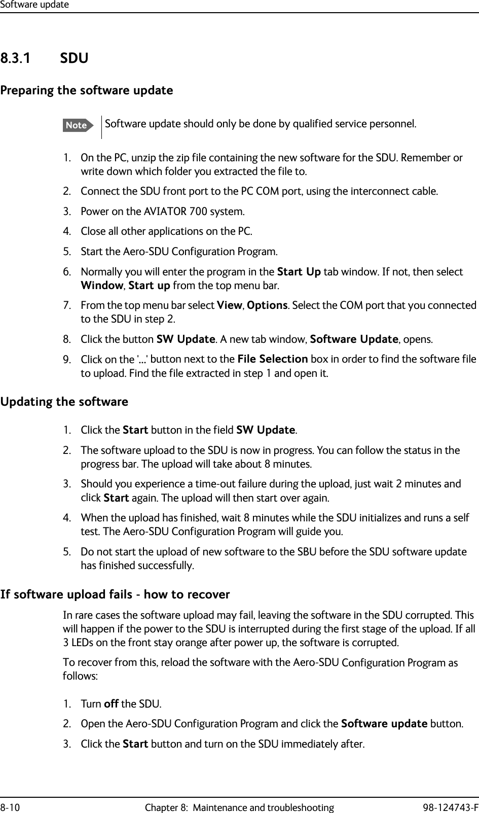
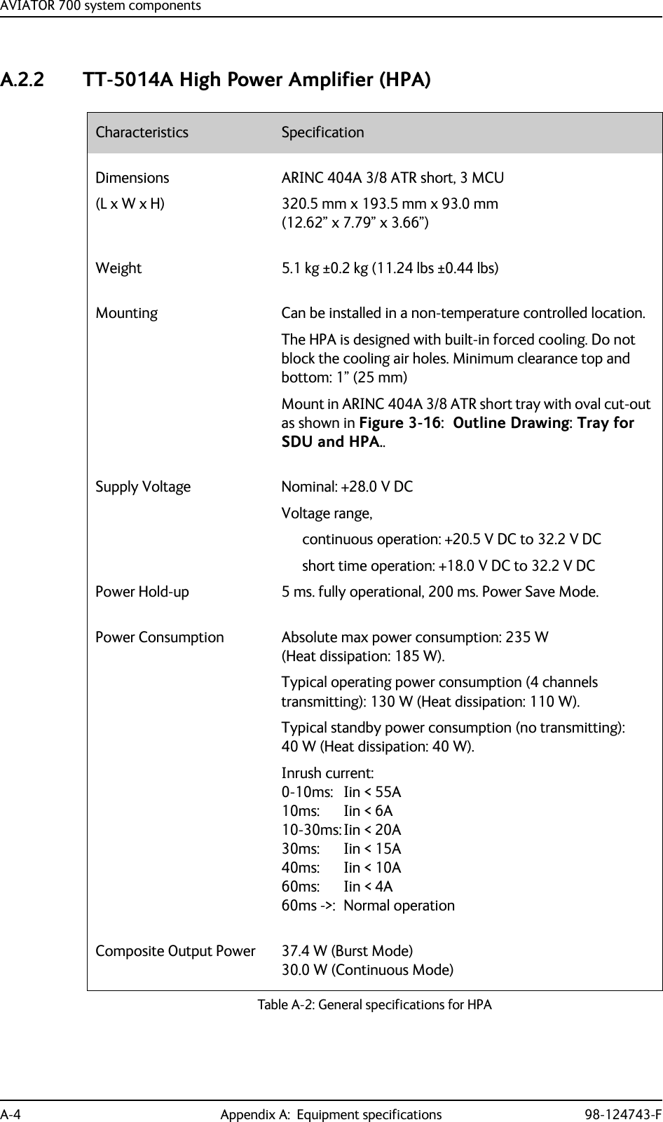
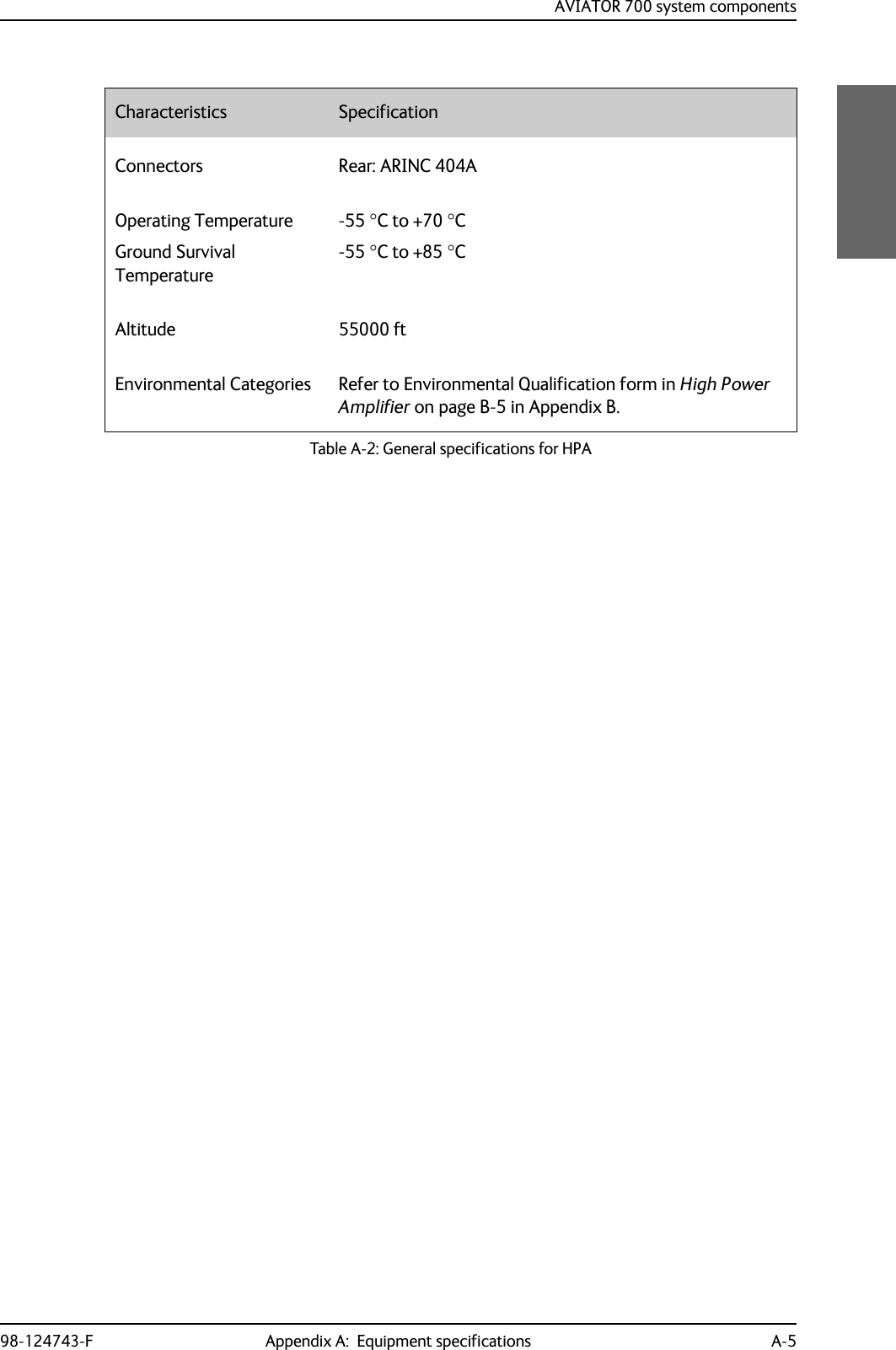
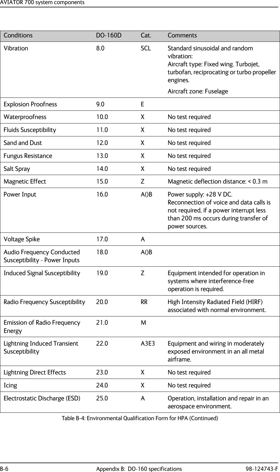
![AVIATOR 700 system components98-124743-F Appendix B: DO-160 specifications B-5B.2.3 High Power AmplifierT&T Part Number: 405014A (AVIATOR 700) or 405014A-THD (AVIATOR 700D)DO-160D string: [(A2)(F2)Z]BBB[SCL]EXXXXXZ[A()B]A[A()B]Z[RR]M[A3E3]XXARTCA/DO-160D Change NumbersChange Number Date of Issue Title SectionChange No. 1 Dec. 14, 2000 VibrationRadio Frequency Susceptibility8.020.0Change No. 2 June 12, 2001 Power InputAudio Frequency Conducted Susceptibility - Power Inputs16.018.0Table B-3: RTCA/DO-160D Change Numbers, HPAConditions DO-160D Cat. CommentsTemperature and Altitude 4.0 A2 and F2Installation in non-controlled temperature locations and inside or outside pressurized locations.Low Temperature 4.5.1 Min. operating low temperature: -55°CHigh Temperature 4.5.2 & 4.5.3 Max. operating high temperature: +70°CIn-Flight Loss of Cooling 4.5.4 Z Continuous operation at 40°C, tested with internal fan turned off.Use the recommended tray and leave at least 1 inch (25 mm) of free space above and below the HPA, to allow free airflow.The HPA is overheat protected.External forced cooling is not recommended.Altitude 4.6.1 Max. altitude: 55000 ftDecompression 4.6.2 Decompression at 55000 ftOverpressure 4.6.3 Overpressure at -15000 ftTemperature Variation 5.0 B Installation within non-temperature-controlled location: 5°C/min.Humidity 6.0 B Severe humidity: 95% relative humidity at 38°C to 65°C for 240 hours.Installation within non-environmentally controlled zones.Operational Shocks and Crash Safety7.0 B Equipment tested to: Standard operational shocks and crash safety.Table B-4: Environmental Qualification Form for HPA](https://usermanual.wiki/Thrane-and-Thrane-A-S/AVIATOR700.Installation-Manual/User-Guide-4022295-Page-349.png)
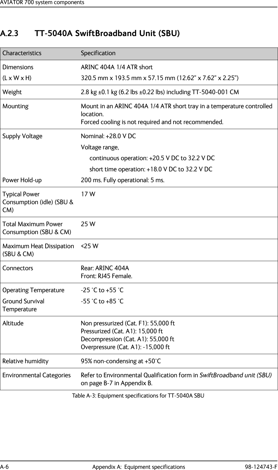
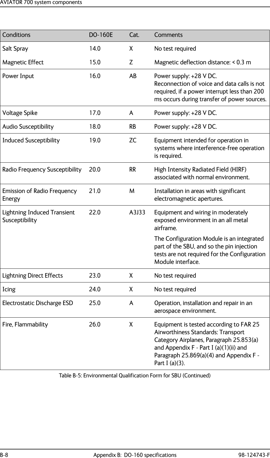
![AVIATOR 700 system components98-124743-F Appendix B: DO-160 specifications B-7B.2.4 SwiftBroadband unit (SBU)T&T Part Number: 405040A (AVIATOR 700) or 405040A-THD (AVIATOR 700D)DO-160E string: [(A1)(F1)X]CAB[SB2M]ExxxxxZ[AB]A[RB][ZC][RR]M[A3J33]XXAXConditions DO-160E Cat. CommentsTemperature and Altitude 4.0 A1, F1 Installation in temperature controlled areas and inside or outside pressurized locations.Low Temperature 4.5.1 & 4.5.2 Short time operating low is -40°C. Unit is active, but inoperable until the unit temperature is > -30°C.Min. operational temperature is -25°C.High Temperature 4.5.3 & 4.5.4 Short time operating high (30 min.): +70°CMax. operating high temperature is +55°CIn-Flight Loss of Cooling 4.5.5 X Forced cooling is not required and not recommended.Altitude 4.6.1 Max. altitude: 55000 ftDecompression 4.6.2 Decompression test at 55000 ftOverpressure 4.6.3 Overpressure at -15000 ftTemperature Variation 5.0 C Installation within temperature controlled areas: 2°C/min.Humidity 6.0 A Standard Humidity: 95% relative humidity at 38°C to 50°C for 48 hours.Installation within environmentally controlled zonesOperational Shocks and Crash Safety7.0 B Equipment tested to: Standard operational shock and crash safety.Vibration 8.0 S, B2, MEquipment tested without shock mounts to Category S, Curve B2 and Curve M.Explosion Proofness 9.0 E Not hermetically sealed equipmentWaterproofness 10.0 X No test requiredFluids Susceptibility 11.0 X No test requiredSand and Dust 12.0 X No test requiredFungus Resistance 13.0 X No test requiredTable B-5: Environmental Qualification Form for SBU](https://usermanual.wiki/Thrane-and-Thrane-A-S/AVIATOR700.Installation-Manual/User-Guide-4022295-Page-351.png)
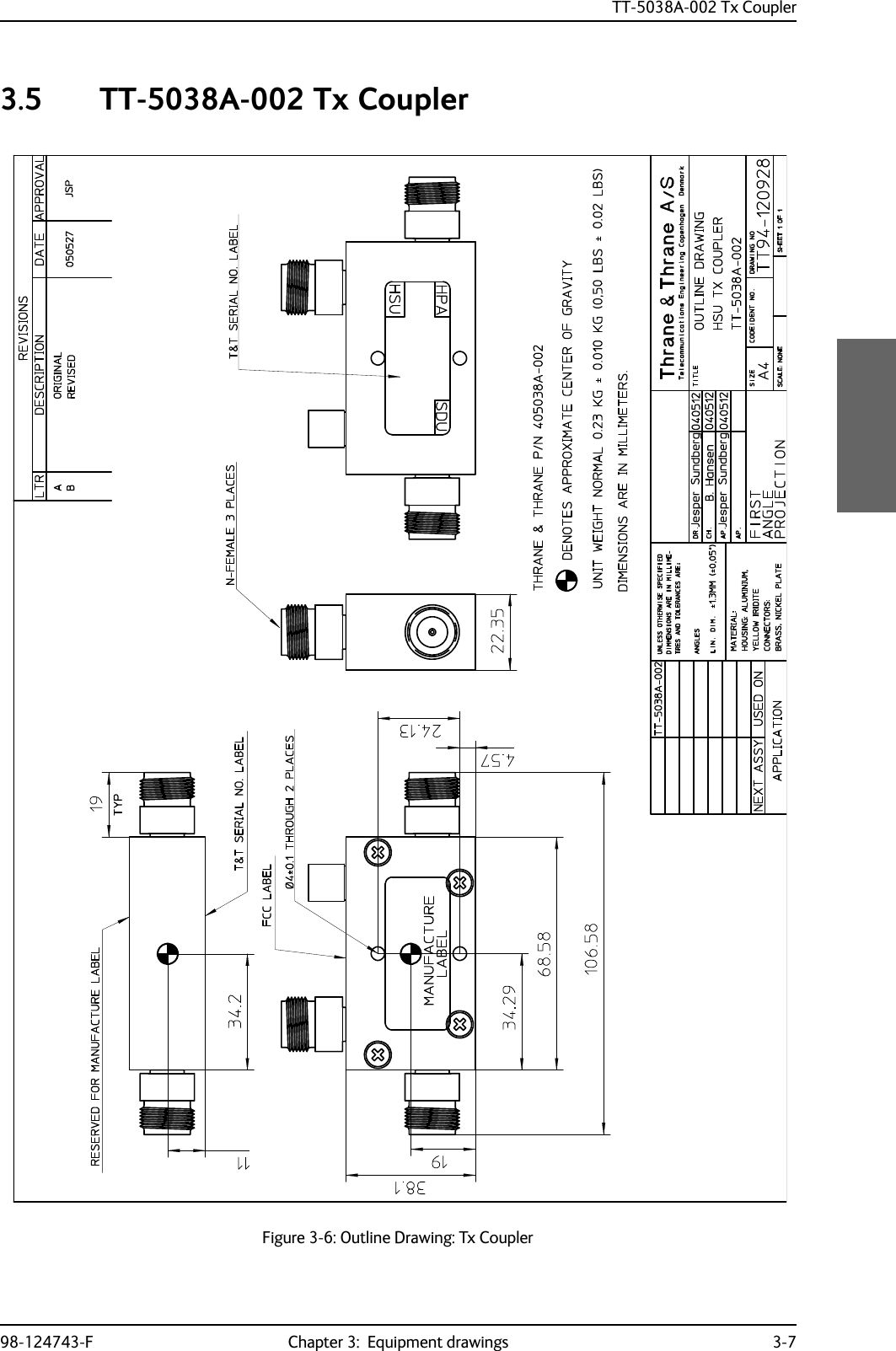
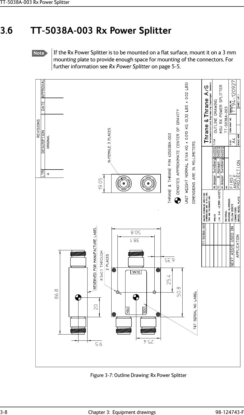
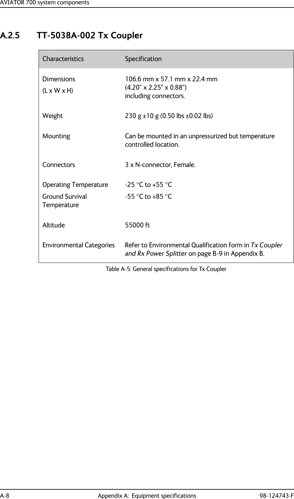
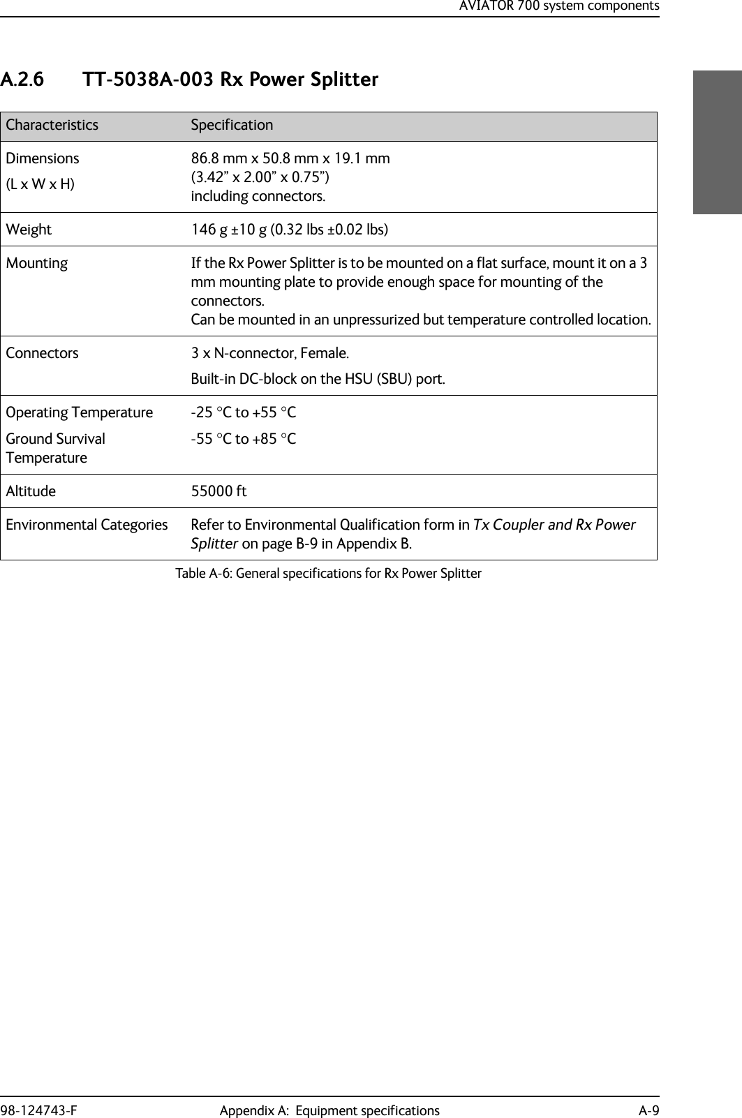
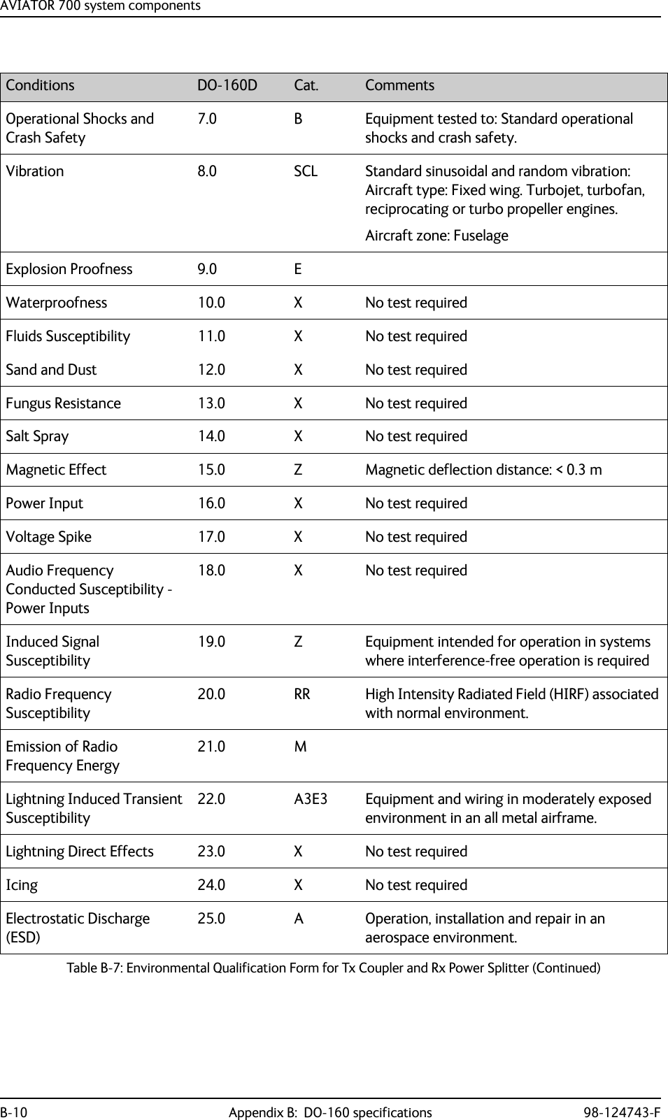
![AVIATOR 700 system components98-124743-F Appendix B: DO-160 specifications B-9B.2.5 Configuration Module (CM) for SBUT&T Part Number: 405040A-001DO-160E string: Please refer to the section SwiftBroadband unit (SBU) on page B-7, as the Configuration Module is an integral part of the SBU during normal operation and tests. However, the section 25 Category A test is performed on the Configuration Module as an individual LRU.B.2.6 Tx Coupler and Rx Power SplitterT&T Part Numbers: 405038A-002 and 405038A-003DO-160D string: [(A1)(F1)X]CBB[SCL]EXXXXXZXXXZ[RR]M[A3E3]XXARTCA/DO-160D Change NumbersChange Number Date of Issue Title SectionChange No. 1 Dec. 14, 2000 VibrationRadio Frequency Susceptibility8.020.0Change No. 2 June 12, 2001 Power InputAudio Frequency Conducted Susceptibility - Power Inputs16.018.0Table B-6: RTCA/DO-160D Change Numbers, Tx Coupler and Rx Power SplitterConditions DO-160D Cat. CommentsTemperature and Altitude 4.0 A1 and F1Installation in controlled temperature locations and inside or outside pressurized locations.Low Temperature 4.5.1 Min. operating low temperature: -25°CHigh Temperature 4.5.2 & 4.5.3 Max. operating high temperature: +55°CIn-Flight Loss of Cooling 4.5.4 X Forced cooling is not recommended.Altitude 4.6.1 Max. altitude: 55000 ftDecompression 4.6.2 Decompression at 55000 ftOverpressure 4.6.3 Overpressure at -15000 ftTemperature Variation 5.0 C Installation within controlled temperature locations: 2°/min.Humidity 6.0 B Severe humidity: 95% relative humidity at 38°C to 65°C for 240 hours.Installation within non-environmentally controlled zones.Table B-7: Environmental Qualification Form for Tx Coupler and Rx Power Splitter](https://usermanual.wiki/Thrane-and-Thrane-A-S/AVIATOR700.Installation-Manual/User-Guide-4022295-Page-353.png)
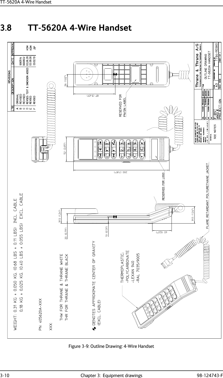
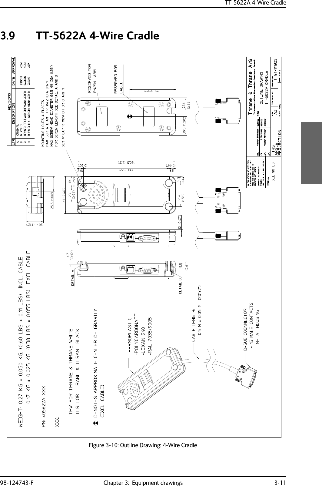
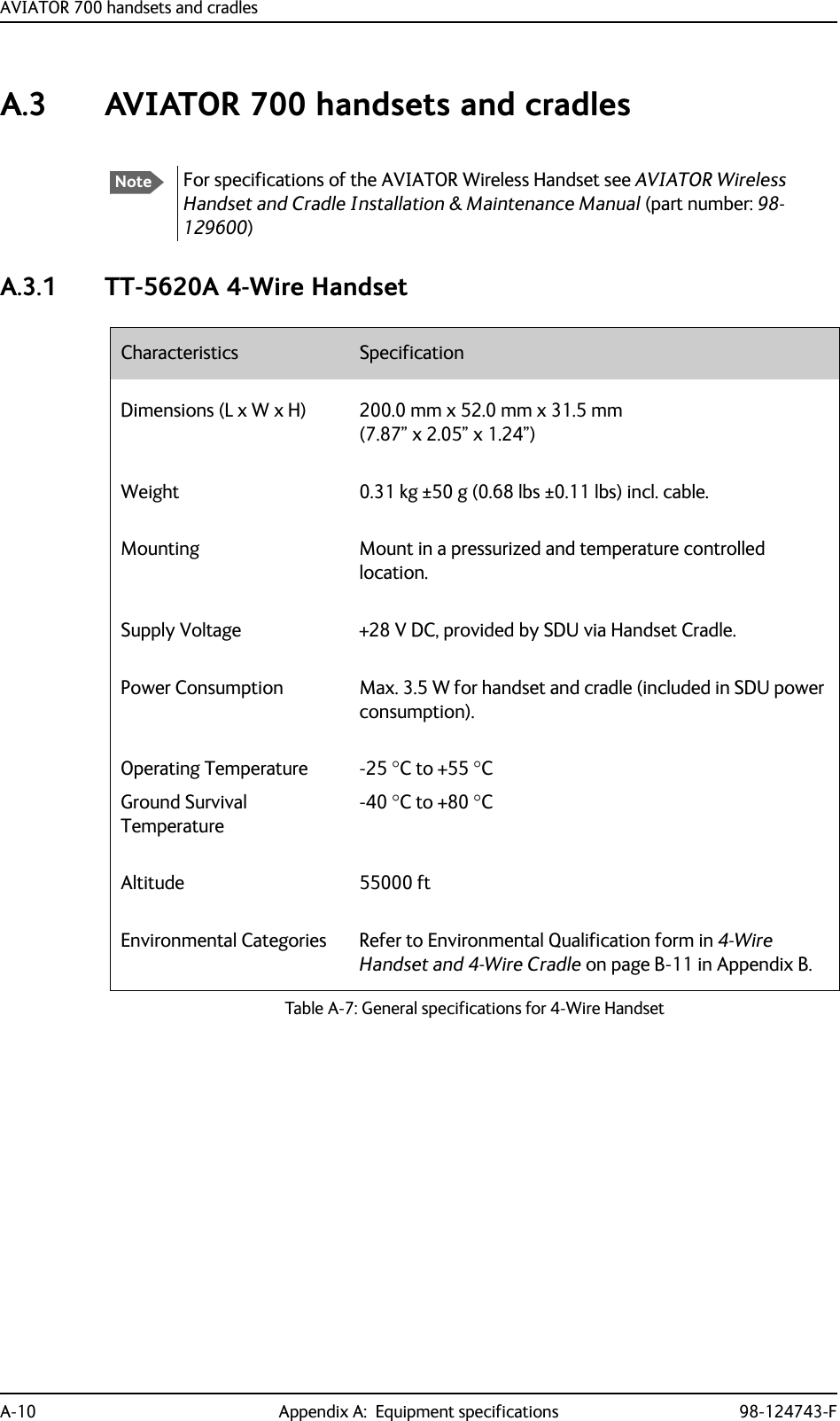
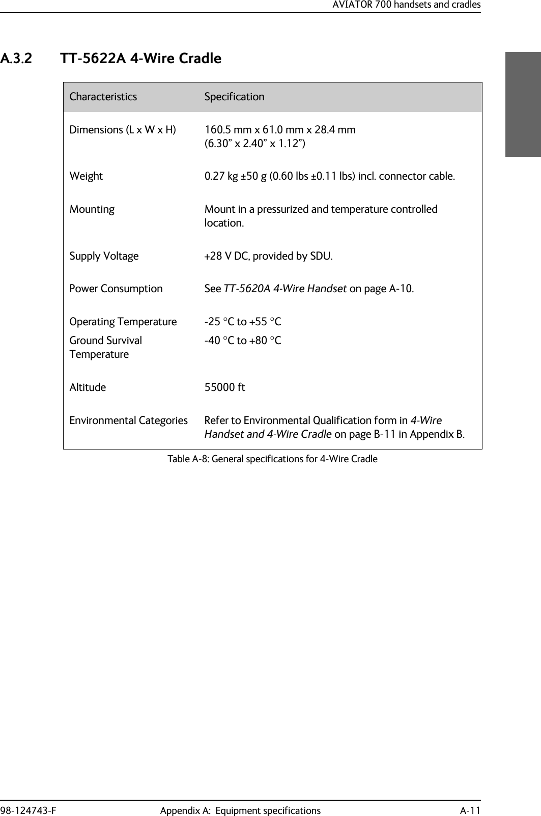
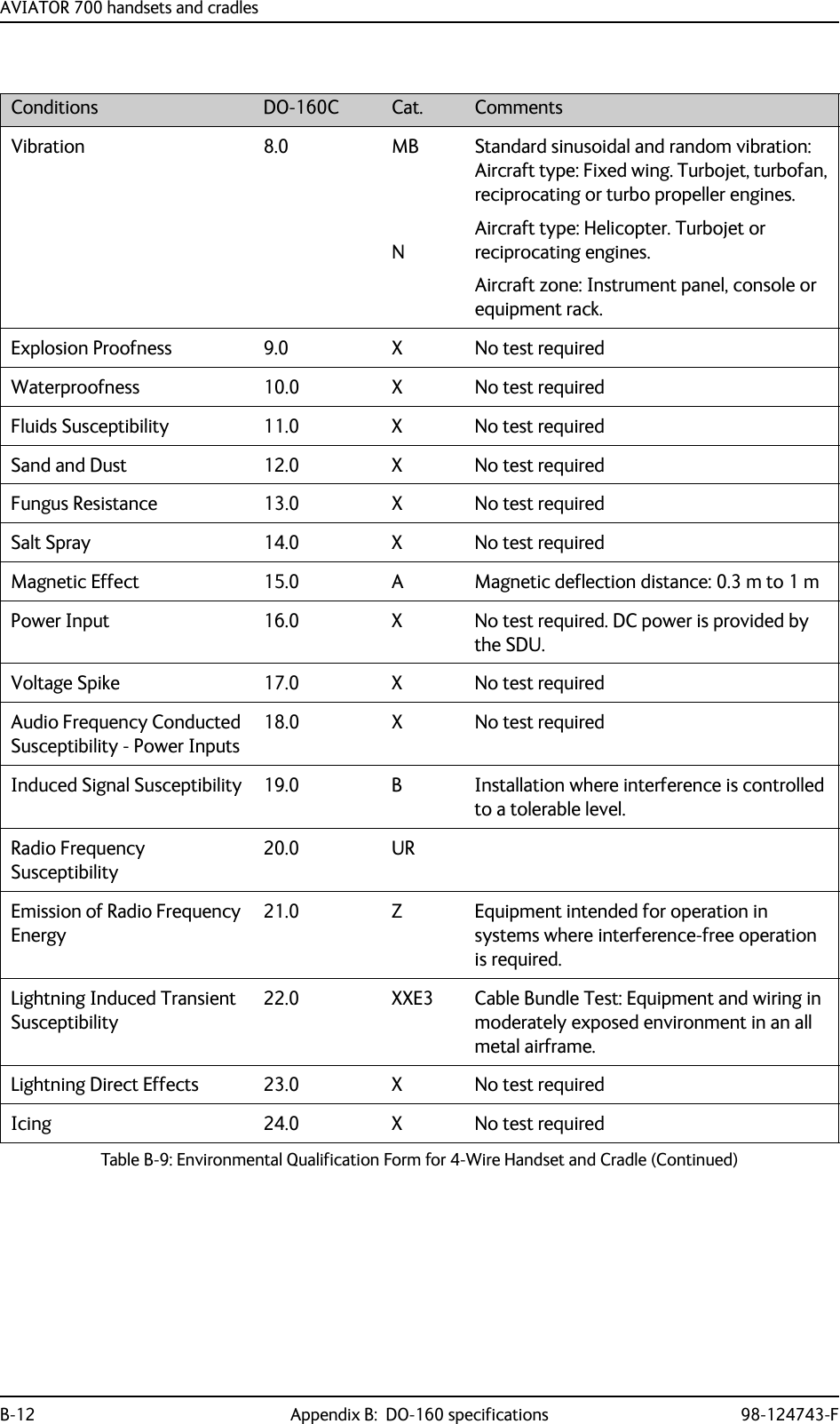
![AVIATOR 700 handsets and cradles98-124743-F Appendix B: DO-160 specifications B-11B.3 AVIATOR 700 handsets and cradlesB.3.1 4-Wire Handset and 4-Wire CradleT&T Part Number: 405620A-THW / 405620A-THR / 405622A-THW / 405622A-THRDO-160C String: A1-BA[MNB]XXXXXXAXXXB[UR]ZXXE3XXNoteFor DO-160 specifications of the AVIATOR Wireless Handset see AVIATOR Wireless Handset and Cradle Installation & Maintenance Manual (part number: 98-129600)RTCA/DO-160C Change NumbersChange Number Date of Issue Title SectionChange No. 2 June 19, 1992 Lightning Induced Transient Susceptibility 22.0Change No. 3 May 13, 1993 Radio Frequency Susceptibility 20.0Table B-8: RTCA/DO-160C Change Numbers, 4-Wire Handset and CradleConditions DO-160C Cat. CommentsTemperature and Altitude 4.0 A1 Installation in controlled temperature and pressurized location.Low Temperature 4.5.1 Min. operating low temperature: -25°CHigh Temperature 4.5.2 & 4.5.3 Max. operating high temperature: +55°CIn-Flight Loss of Cooling 4.5.4 - No forced cooling required.Altitude 4.6.1 Max. altitude: 55000 ft Decompression 4.6.2 Decompression at 55000 ftOverpressure 4.6.3 Overpressure at -15000 ftTemperature Variation 5.0 B Installation within partially or non-controlled temperature locations: 5°C/min.Humidity 6.0 A Standard Humidity: 95% relative humidity at 38°C to 50°C for 48 hours.Installation within environmentally controlled zonesOperational Shocks and Crash SafetyOperational ShockCrash Safety7.07.27.3YesYesYesEquipment tested to: Standard operational shocks and crash safety.Table B-9: Environmental Qualification Form for 4-Wire Handset and Cradle](https://usermanual.wiki/Thrane-and-Thrane-A-S/AVIATOR700.Installation-Manual/User-Guide-4022295-Page-355.png)
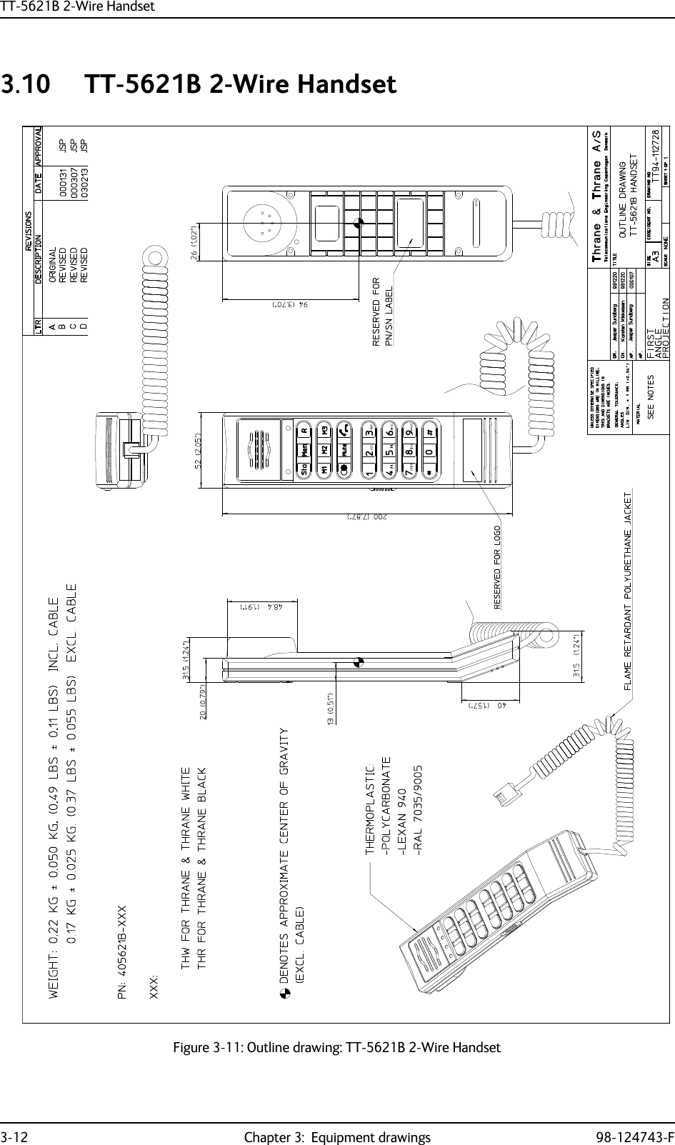
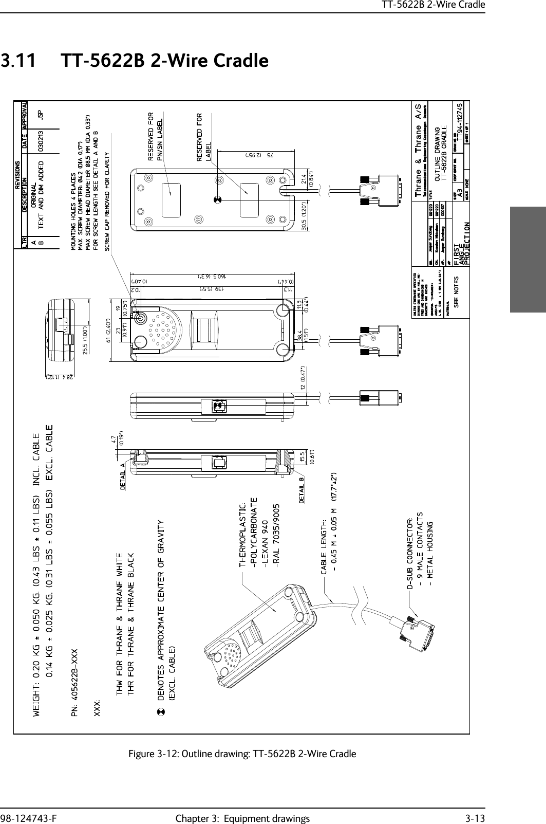
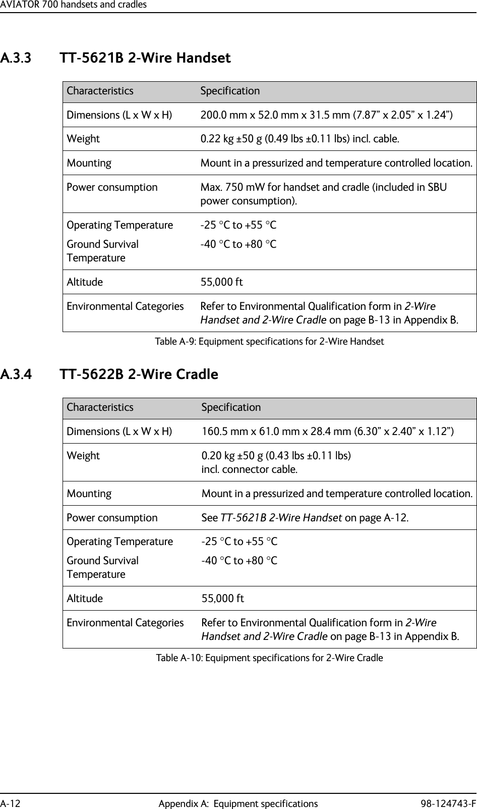
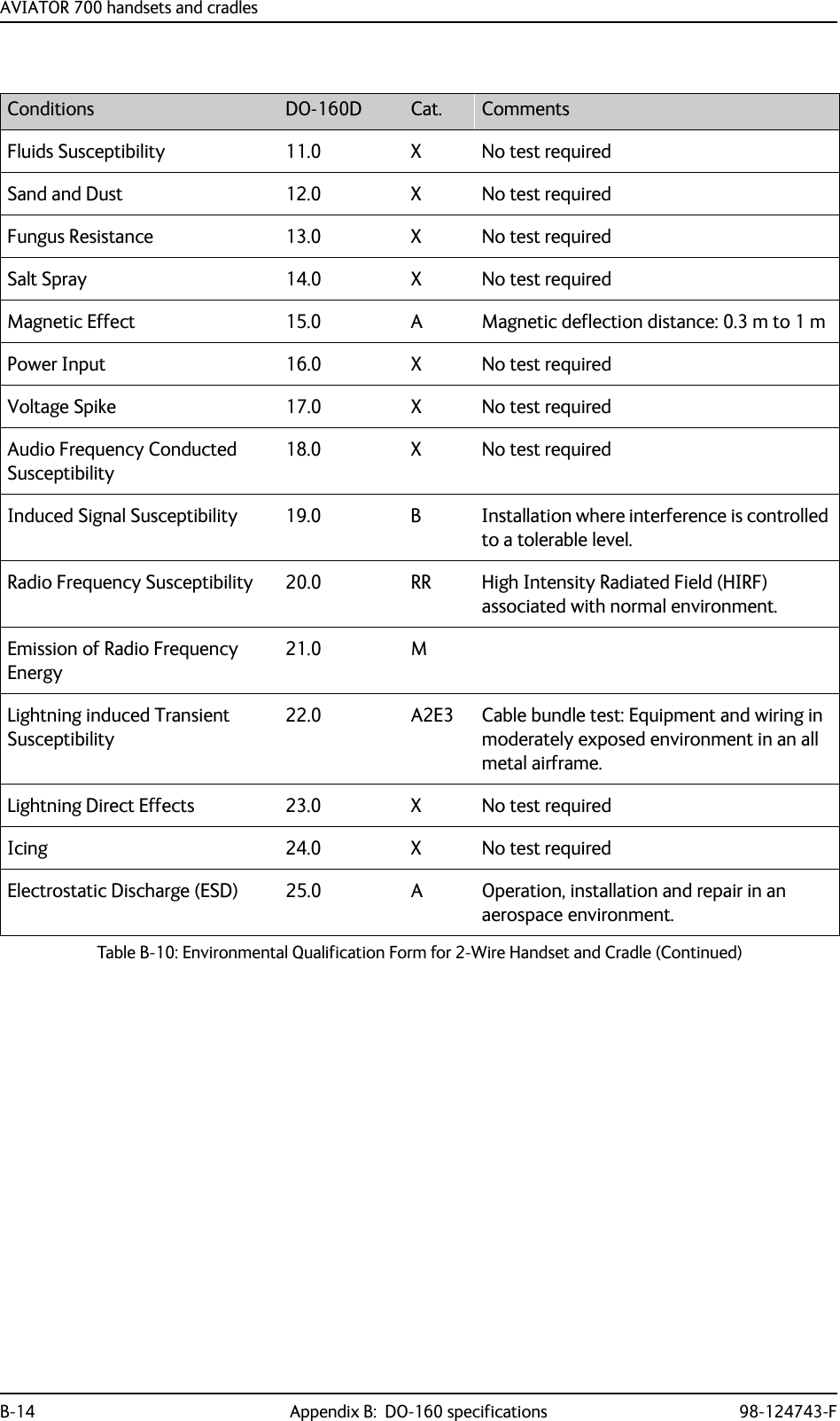
![AVIATOR 700 handsets and cradles98-124743-F Appendix B: DO-160 specifications B-13B.3.2 2-Wire Handset and 2-Wire CradleT&T Part Number: 405621B-THW / 405621B-THR / 405622B-THW / 405622B-THRDO-160C String: [A1X]CAB[(SMB2)(SM)(UFF1)]XXXXXXAXXXB[RR]M[A2E3]XXAConditions DO-160D Cat. CommentsTemperature and Altitude 4.0 A1 Installation in controlled temperature and pressurized location.Low Temperature 4.5.1 Min. operating low temperature: -25°CHigh Temperature 4.5.2 & 4.5.3 Max. operating high temperature: +55°CIn-Flight Loss of Cooling 4.5.4 X No forced cooling required.Altitude 4.6.1 Max. altitude: 55000 ftDecompression 4.6.2 Decompression at 55000 ftOverpressure 4.6.3 Overpressure test at -15000 ftTemperature Variation 5.0 C Installation within controlled temperature locations: 2°/min.Humidity 6.0 A Standard Humidity: 95% relative humidity at 38°C to 50°C for 48 hours.Installation within environmentally controlled zones.Operational Shocks and Crash Safety7.0 B Equipment tested to: Standard operational shocks and crash safety.Vibration 8.0 S2B2SMUFF1Standard random vibration:Aircraft type: Fixed wing. Turbojet or turbofan engines.Standard sinusoidal vibration:Aircraft type: Fixed wing. Reciprocating or turbo propeller engines.Robust Sine-on-Random vibration:Aircraft type: Helicopter. Turbojet or reciprocating engines.Aircraft zone: Instrument panel, console or equipment rack.Explosion Proofness 9.0 X No test requiredWaterproofness 10.0 X No test requiredTable B-10: Environmental Qualification Form for 2-Wire Handset and Cradle](https://usermanual.wiki/Thrane-and-Thrane-A-S/AVIATOR700.Installation-Manual/User-Guide-4022295-Page-357.png)
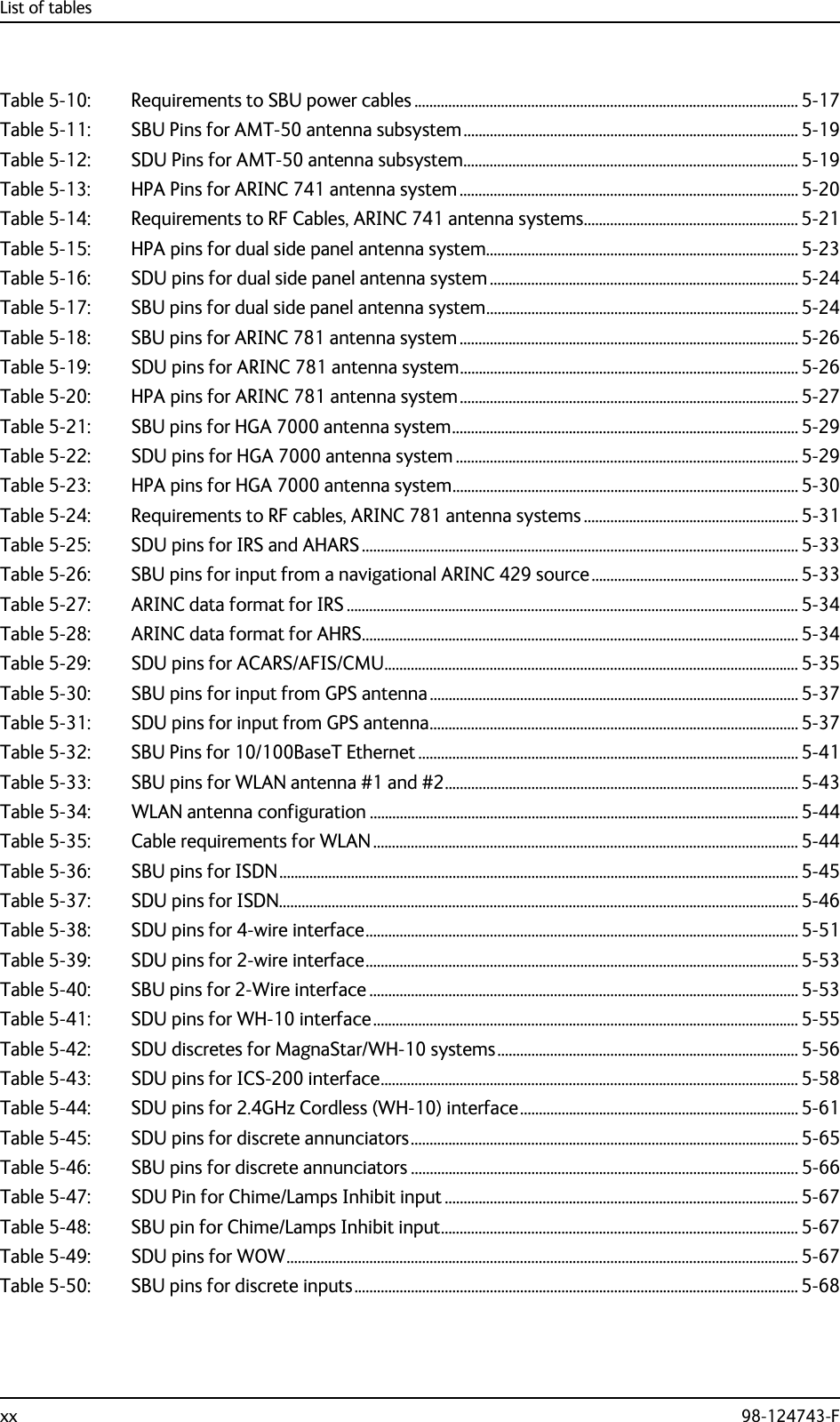
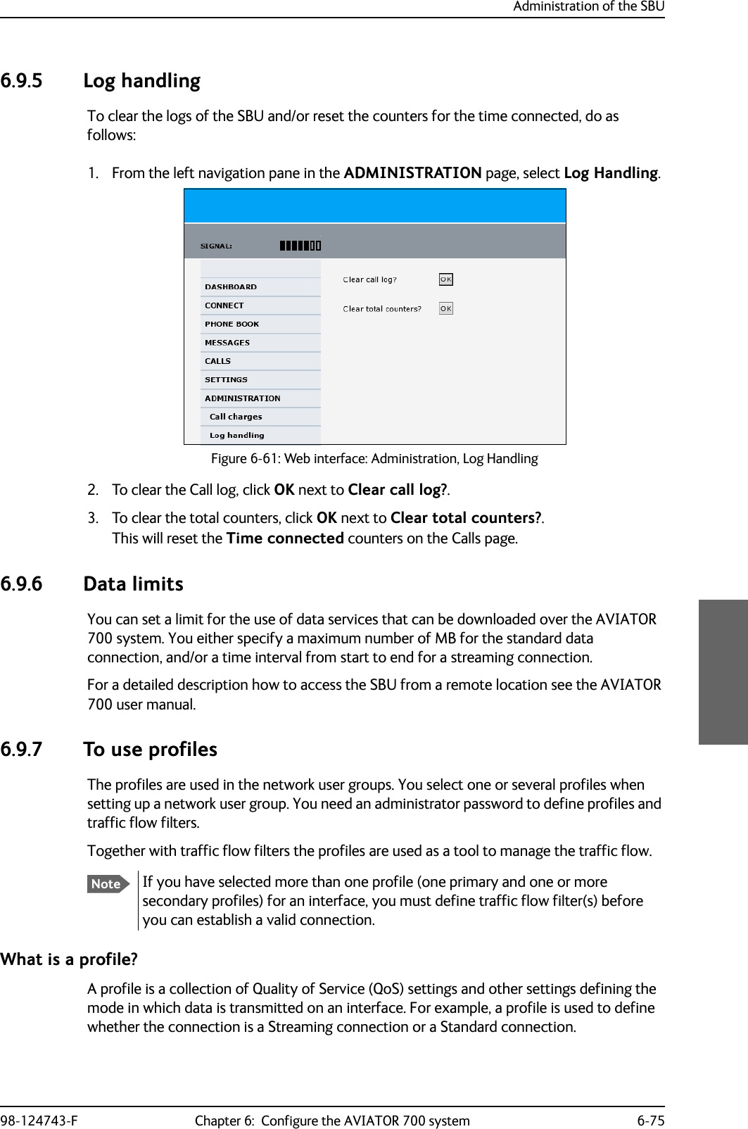
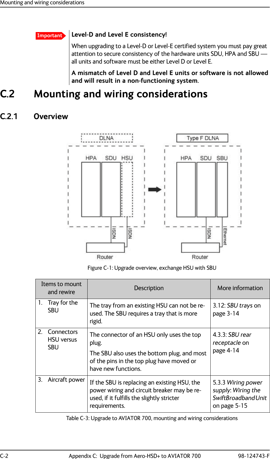
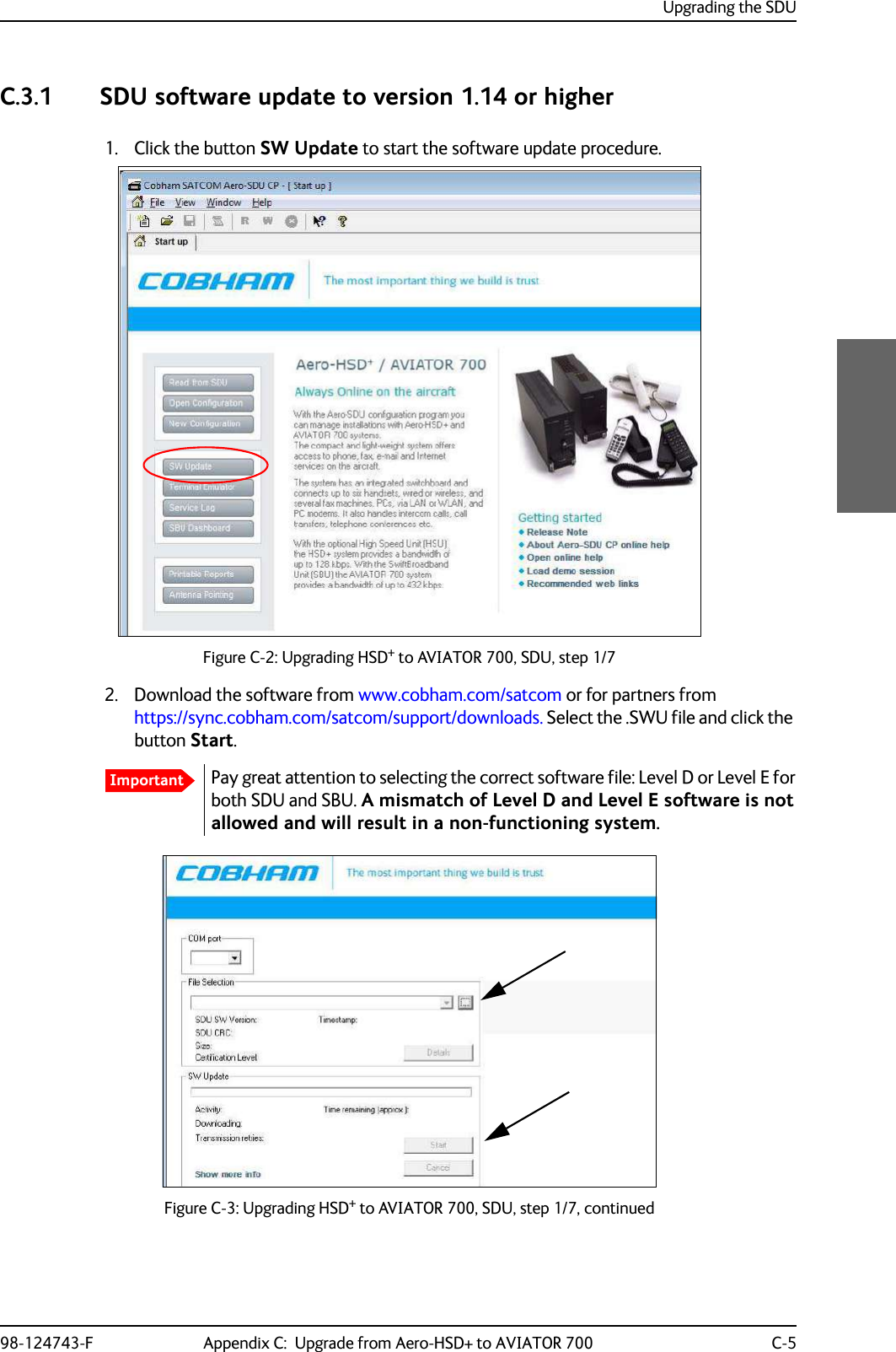
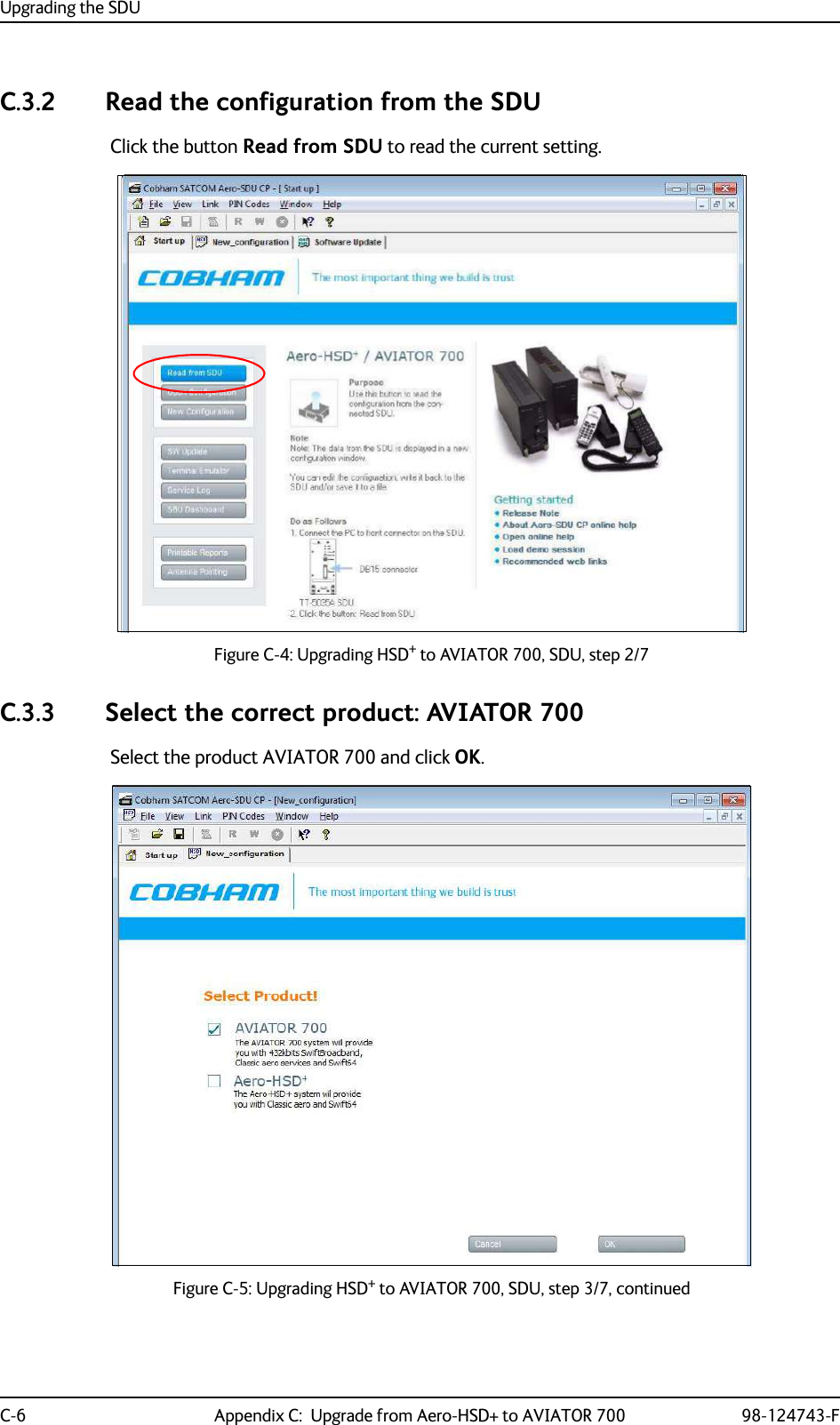
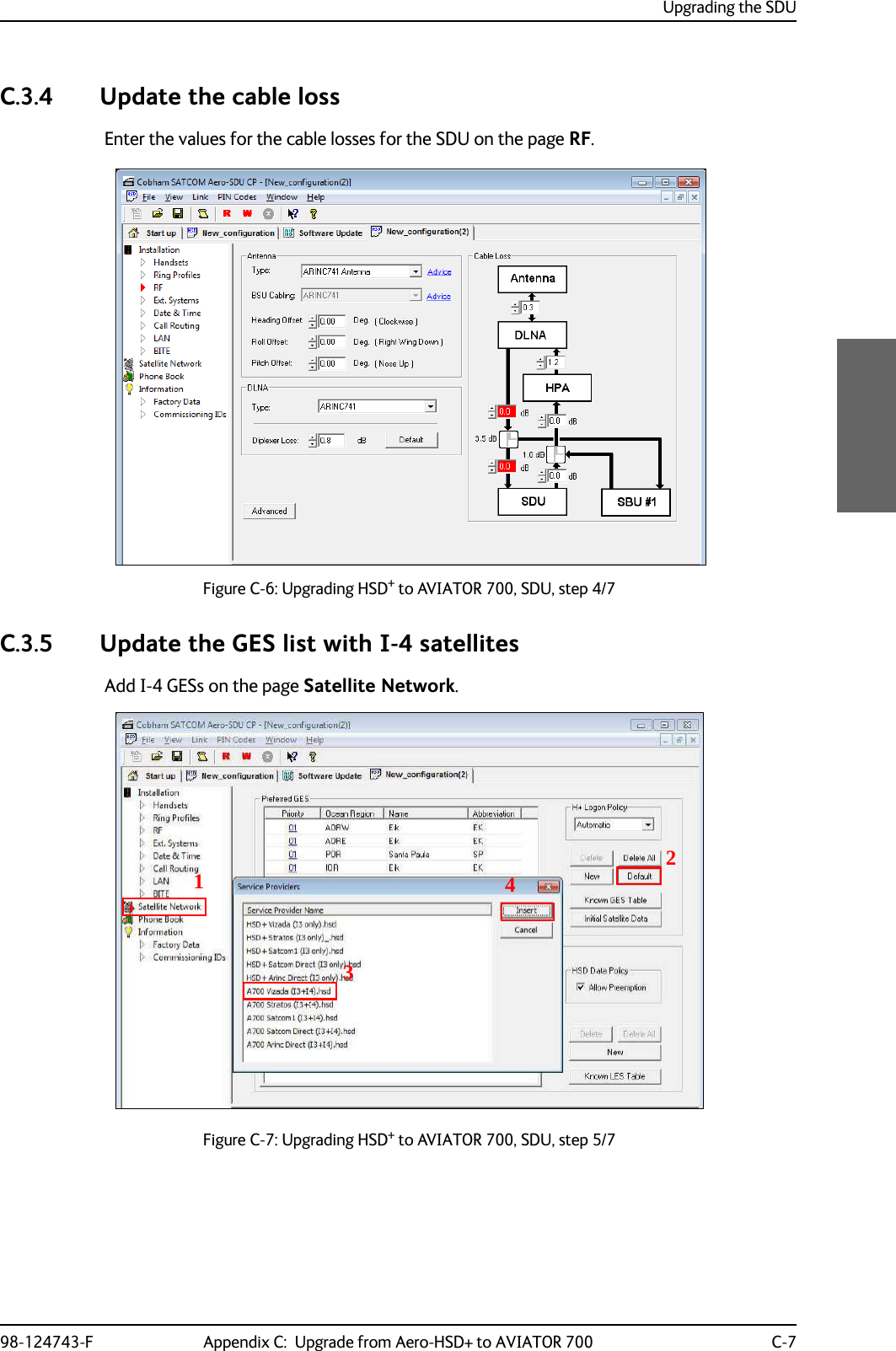
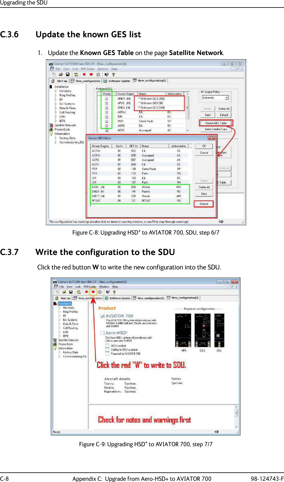
![98-124743-F C-1Appendix CUpgrade from Aero-HSD+ to AVIATOR 700 CC.1 Avionics hardware neededDepending on your current HSD+ Level E installation you need the following items to upgrade your system to AVIATOR 700 (Level E) or AVIATOR 700D (Level D): Table C-1: Items needed for upgrading to AVIATOR 700 Level E or AVIATOR 700D (Level D)AVIATOR 700 (Level E) AVIATOR 700D (Level D)Items needed for existing Aero-HSD+ system Aero-HSD+4 channelsAero-HSD+5 channelsAero-HSD+4 channelsAero-HSD+5 channels 405040A SwiftBroadband Unit (SBU) [without CM] 405040A-THD SwiftBroadband Unit (SBU) [without CM]Connector kit for TT-5040ANew tray for TT-5040A SBU 405040A-001 Configuration Module (CM) for SBU 405040A-005 SDU to SBU Software Interface 405038A-002 TX-Coupler405038A-003 RX Power Splitter405035A-THD Satellite Data Unit (SDU) Level-D405014A-THD High Power Amp (HPA) Level-DTable C-2: Items needed for upgrading for different antenna types Satcom antenna system405013A DLNA Type F 405007A-801 Cobham BSU-7100yes yesyes yesyes yes yes yesyes yes yes yesyes yes yes yesyes yes yes yesyes yesyes yesyes yesyes yesItem HGA-7000 Otheryes yesyes no](https://usermanual.wiki/Thrane-and-Thrane-A-S/AVIATOR700.Installation-Manual/User-Guide-4022295-Page-359.png)
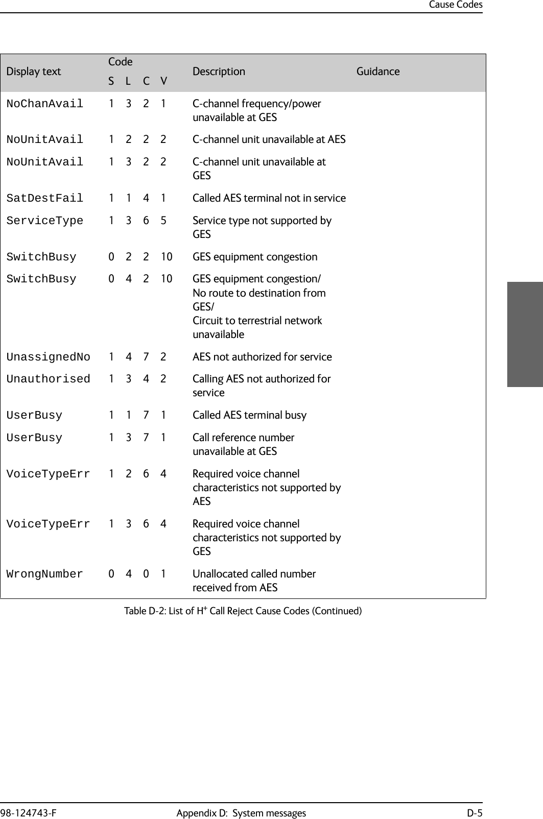
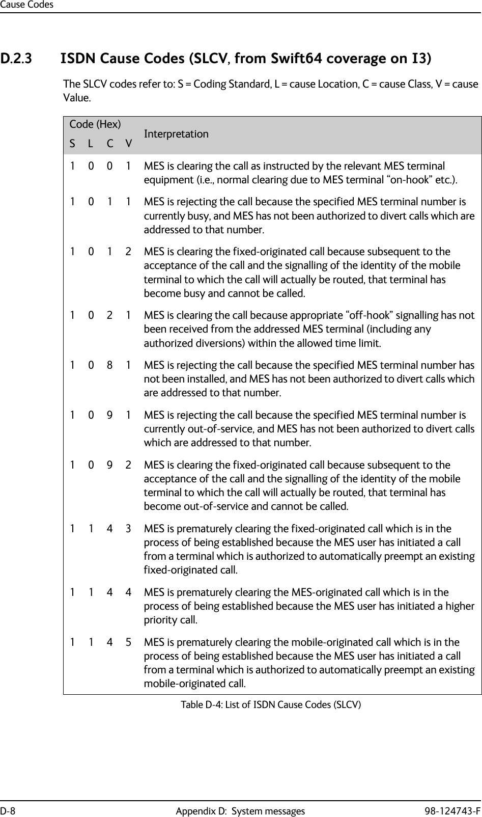
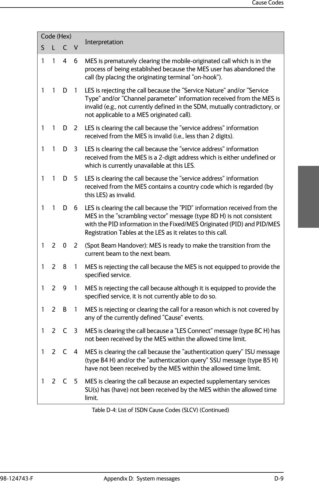
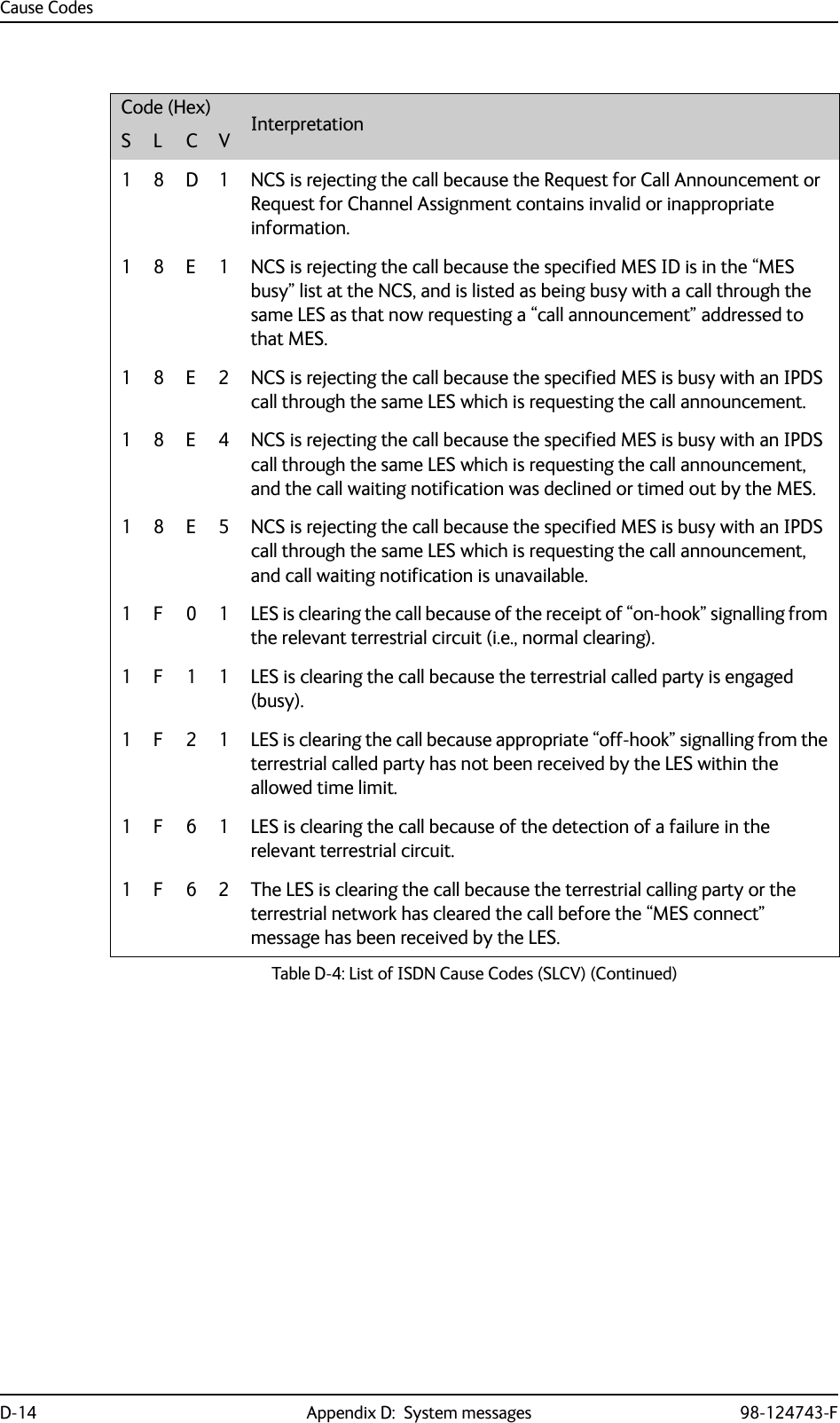
![Cause CodesD-10 Appendix D: System messages 98-124743-F1 2 C 6 MES is clearing the call because the “supplementary services interrogation” ISU (type B2 H), and/or “subscriber digits” SSU (type AD H) messages have not been received by the MES within the allowed time limit.1 2 C 7 MES is clearing the call because a “SCPC channel release” SU (type 8A H) has not been received by the MES, in response to the transmission of a “notification acknowledge” message (type BA H) during the supplementary services call diversion information retrieval process, within the allowed time limit.1 2 C 8 (Spot Beam Handover): MES is clearing the call session in the next beam because the MES did not detect the LESH carrier on the new frequency.1 2 D 1 LES is rejecting the call because the “spot-beam ID” information received from the MES is invalid (i.e., ID is not allocated on satellite in use).1 2 D 2 LES is clearing the call because the “Scrambling Vector” information received from the MES is invalid (i.e., 0000H, 6959H or 7FFFH).1 3 6 2 MES is clearing the call because a long-term interruption in reception has occurred (the definition of a “long-term interruption” depends upon the service type, see Section B).1 3 6 3 A Secondary Functional Centre of a Multi-channel MES is clearing the call because the Primary Functional centre has commanded the Above-decks equipment to re-point to a different Ocean Region.Note: The above text is specific to a Fleet system. However, for the AVIATOR 700 system this SLCV code is relevant when the H+ sub-system is repointing the antenna from one ocean region to another. That will cause the Swift64 sub-system to be pre-empted with the SLCV 1363.1391MES is clearing the call because the call has lasted more than 700 km in linear travelled distance. 1392MES is clearing the call because it has moved out of spot beam coverage.1393MES in “cooperative mode” is clearing the call because of a pre-emption request from the master entity.1451LES is rejecting the call because an appropriate terrestrial circuit is not currently available at this specific LES.1452LES is rejecting the call because an appropriate channel unit and associated terrestrial circuit are not currently available at this LES. [This “cause” is only utilized when there is a permanent “one-to-one” connection between appropriate channel units and their terrestrial circuits].Code (Hex) InterpretationS L C VTable D-4: List of ISDN Cause Codes (SLCV) (Continued)](https://usermanual.wiki/Thrane-and-Thrane-A-S/AVIATOR700.Installation-Manual/User-Guide-4022295-Page-376.png)
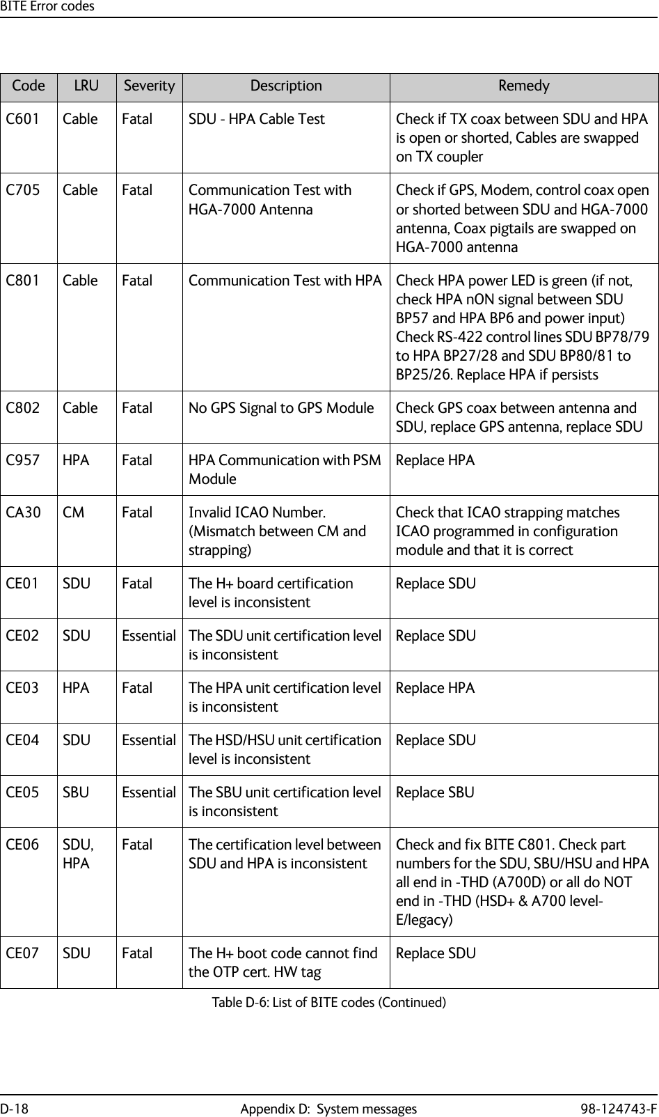
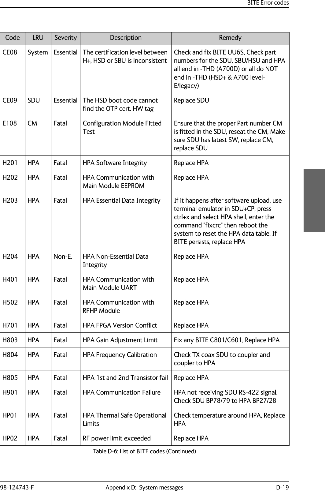
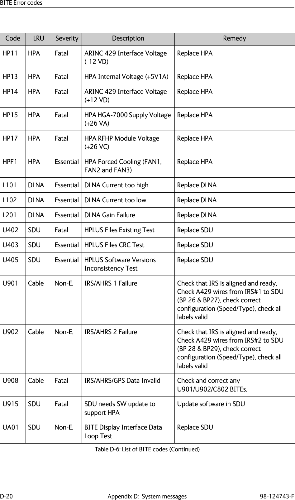
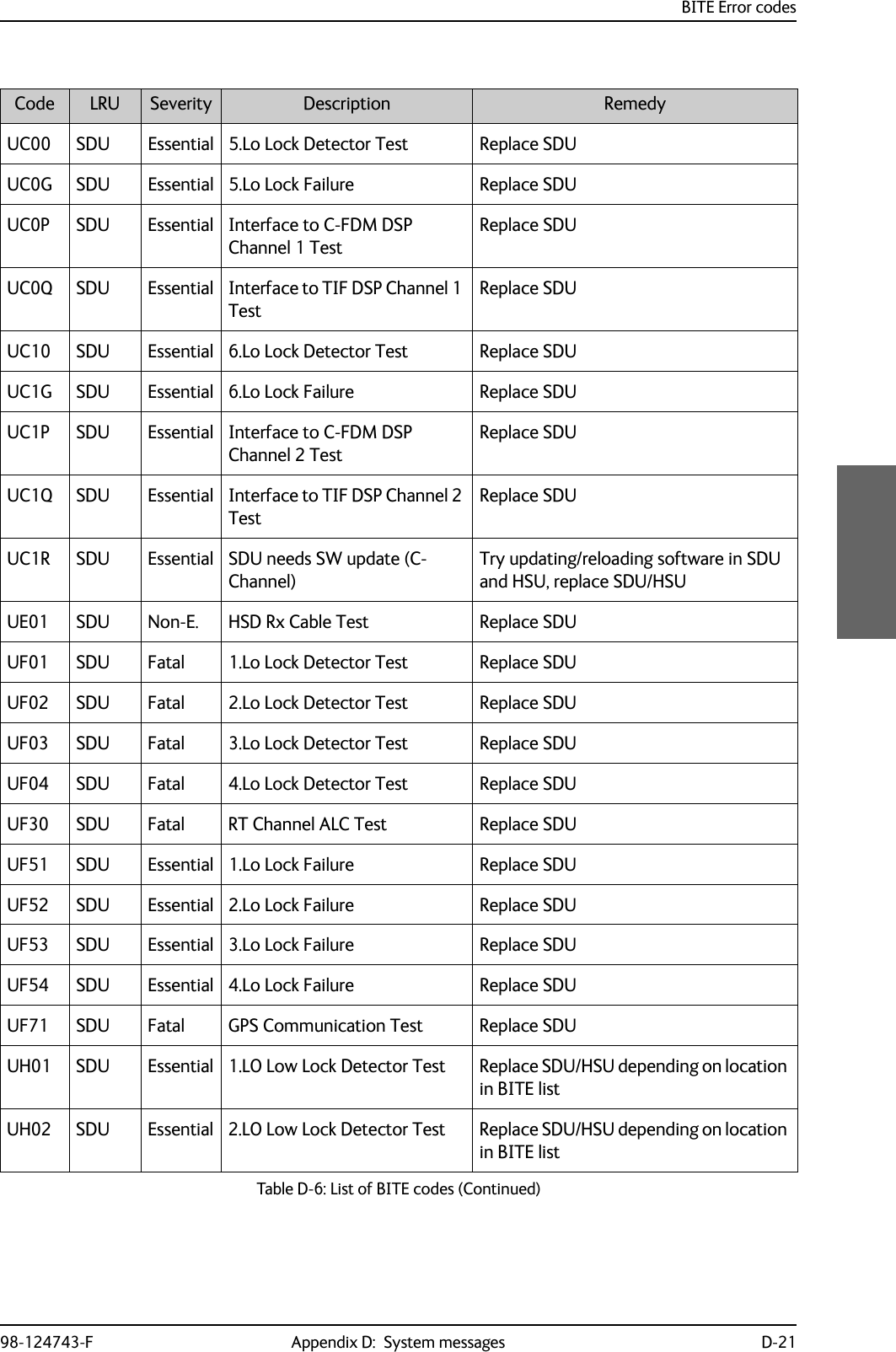
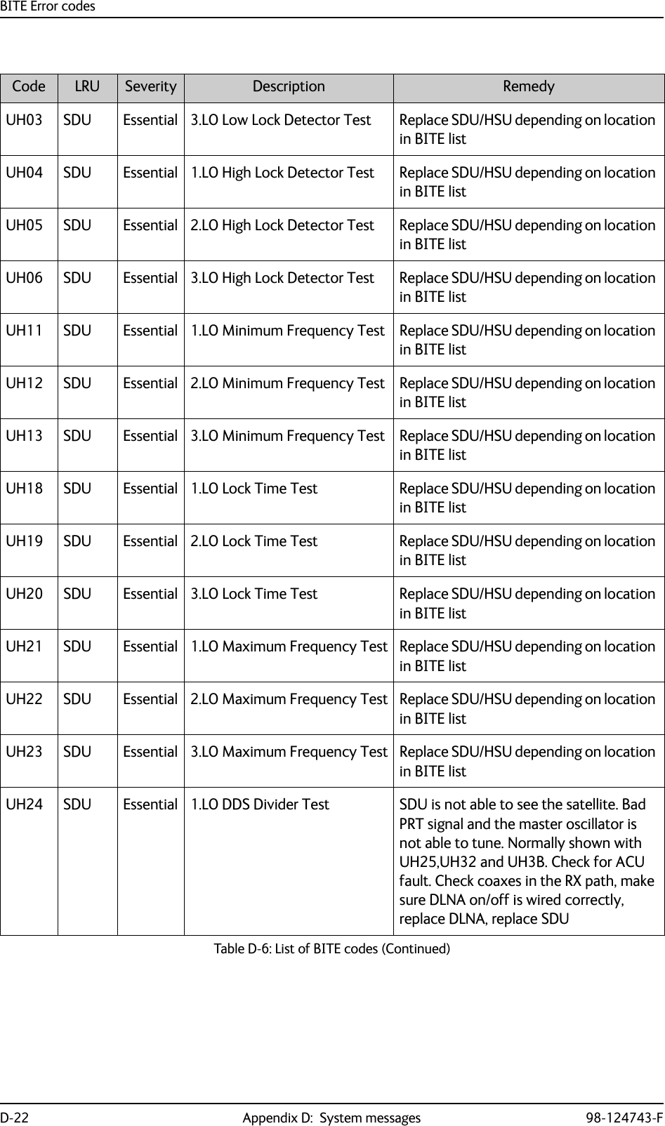
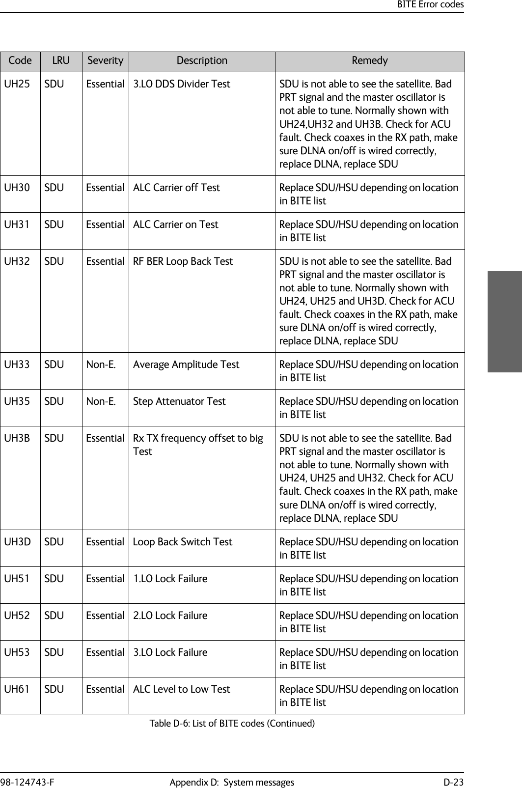
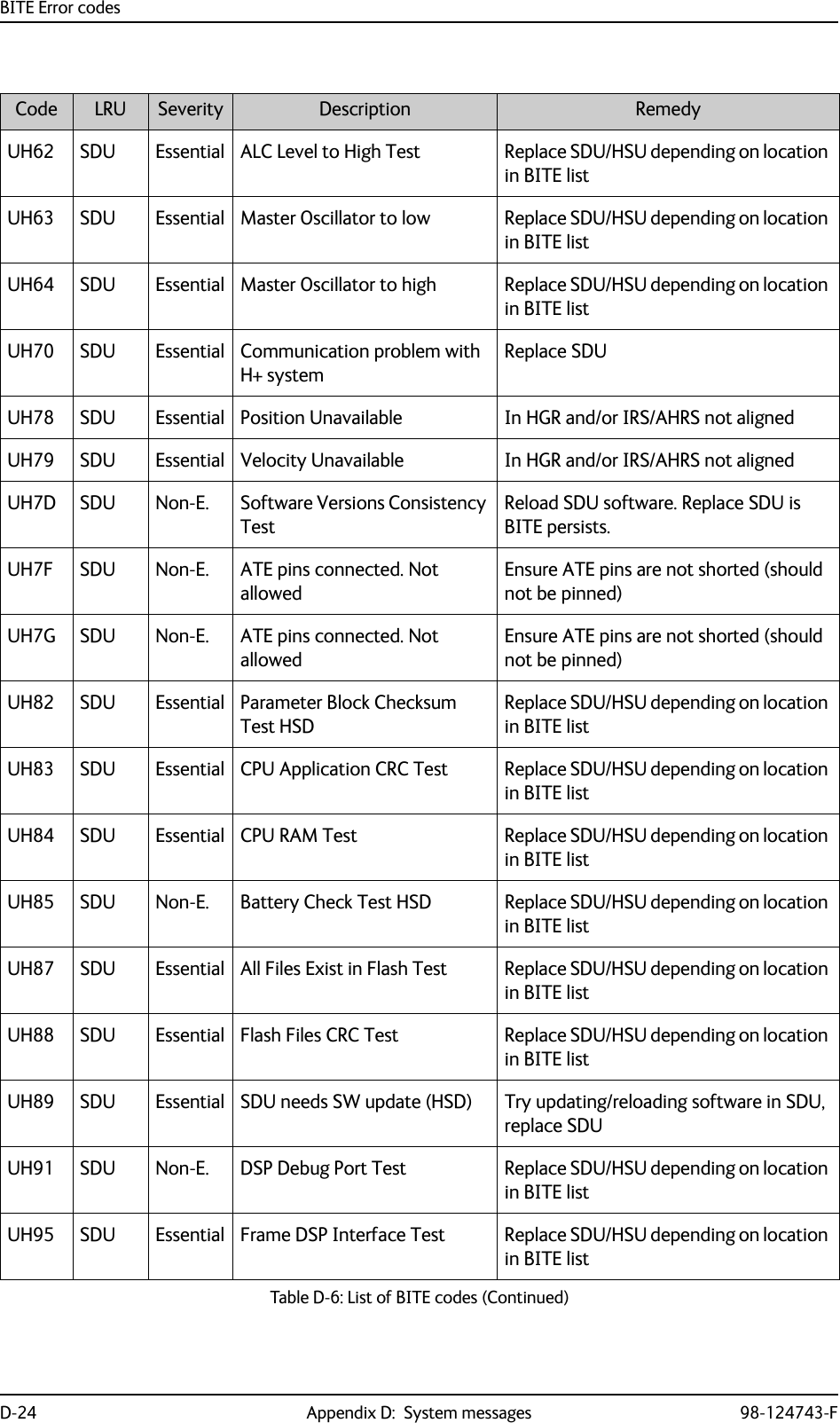
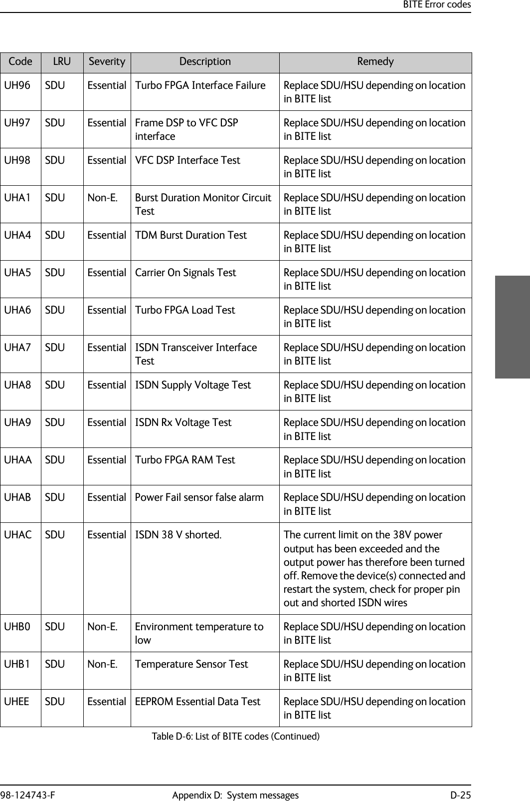
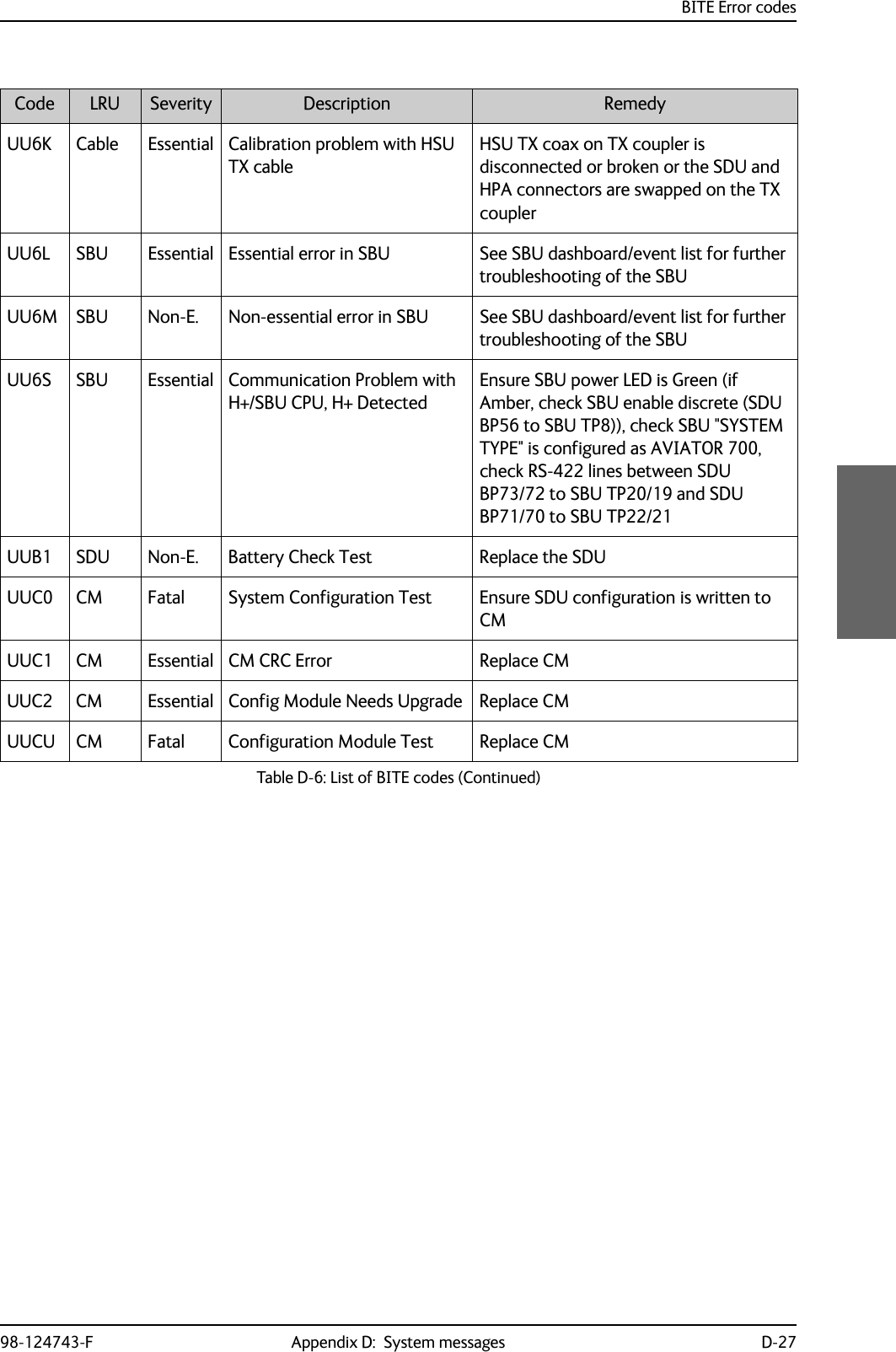
![BITE Error codesD-26 Appendix D: System messages 98-124743-FUHEU SDU Non-E. EEPROM Test Replace SDU/HSU depending on location in BITE listUHP0 SDU Essential Communication Test with HSD-CPUReplace SDU/HSU depending on location in BITE listUHW2 SDU Non-E. Master Oscillator needs calibrationReplace SDU/HSU depending on location in BITE listUU02 SDU Essential Parameter Block Checksum TestWith aircraft outside and nave system up, from terminal emulator enter the command "TX -x -1" and hit enter. The system will reboot and parameter block will be reset. UU10 SDU Essential PRT DSP Interface Test Replace the SDUUU16 SDU Essential UART Loop Back, CPDF (COM12) TestReplace the SDUUU19 SDU Essential SDU needs SW update (H+) Replace the SDUUU1C SDU Non-E. Temperature Sensor Test Replace the SDUUU1D SDU Fatal Environment Temperature Failure, H-PlusReplace the SDUUU20 SDU Non-E. H+ EEPROM Non Essential Data TestReplace the SDUUU21 SDU Fatal H+ EEPROM Essential Data Test Replace the SDUUU23 SDU Essential H+/HSD SW Version Inconsistency TestMake sure SDU & HSU has latest software, replace SDU, replace HSUUU24 SBU Essential H+/SBU SW Version Inconsistency TestMake sure SDU & SBU has latest software, replace SDU, replace SBUUU60 SDU Essential PBX DSP Interface Test Replace the SDUUU6H SDU Essential Communication Problem with HSD CPU, H+ DetectedCheck "location" of BITE with SDU+CP Terminal Emulator "list" or in handset. If location [HSD pcb] reload software in SDU and replace SDU if BITE persists after reboot. If location [HSU pcb] check Arinc 429 connection to HSU (SDU BP32/33 to HSU TP19/20 and SDU BP34/35 to HSU TP21/22), check HSU power and software version. Replace HSU if persist after rebootCode LRU Severity Description RemedyTable D-6: List of BITE codes (Continued)](https://usermanual.wiki/Thrane-and-Thrane-A-S/AVIATOR700.Installation-Manual/User-Guide-4022295-Page-392.png)
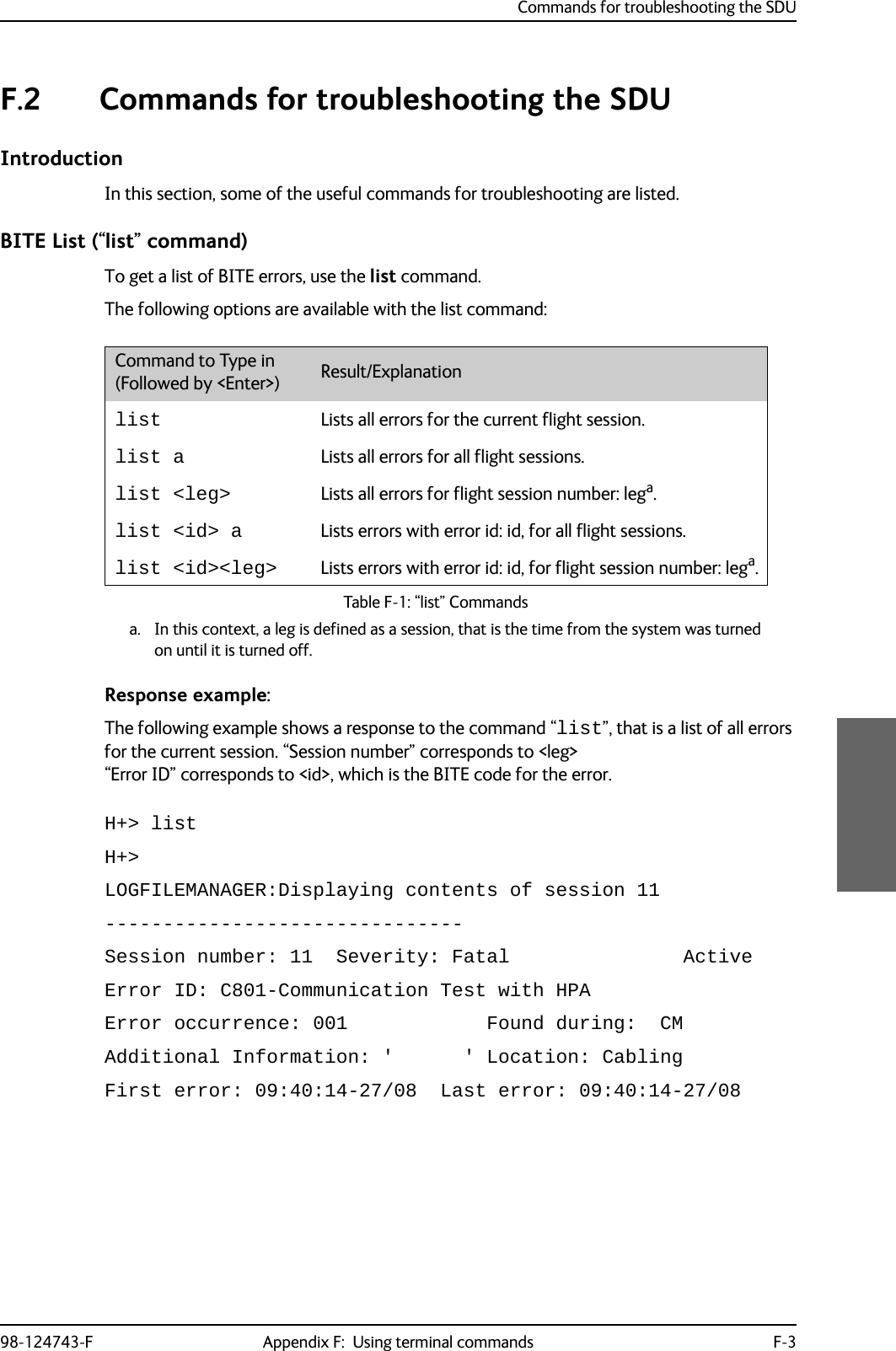
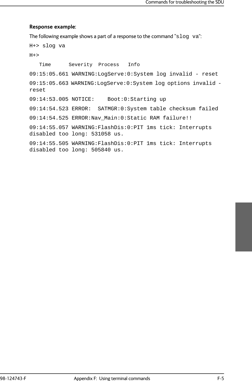
![Commands for troubleshooting the SDUF-4 Appendix F: Using terminal commands 98-124743-FSystem Log (“slog” command)To access the system log, use the slog command. The following options are available with the slog command:Command to Type in (Followed by <Enter>) Result/Explanationslog l <prio>... Inserts text into the system log with priority <prio>a. a. <prio> : Priority limit (one of {facewnid} or 0-7).The priority parameters {facewnid} are defined as:f: System is unusable.a: Action must be taken immediately.c: Critical conditions.e: Error conditions.w: Warning conditions.n: Normal but significant condition.i: Informational.d: Debug-level messages.slog t Shows the priority thresholds.slog tp <prio> Sets the print threshold. Log entries with priority <prio>a or higher will be printed.slog ts <prio> Sets the store threshold. Log entries with priority <prio>a or higher will be stored.slog v[arl] [-p<prio>] [-t<text>] [<count>]Shows the system log as defined by the parameters.Explanation of parameters:a: All entriesr: Reverse orderl : Long time format (toggles between long/short time format) (stickyb)<prio>: a (See table footnote)<text>: Only entries containing <text><count>: Max. number of entries shown (stickyb)b. “Sticky” means this setting is maintained during future command sessions until the setting is changed by the user.slog R Reset system log.Table F-2: “slog” Commands](https://usermanual.wiki/Thrane-and-Thrane-A-S/AVIATOR700.Installation-Manual/User-Guide-4022295-Page-406.png)
![98-124743-F G-1Appendix GReferences GG.1 Applicable standards[1] IEEE Standard for Information technology - Telecommunications and information exchange between systems - Local and metropolitan area networks - Specific requirements Part 3: Carrier sense multiple access with collision detection (CSMA/CD) access method and physical layer specifications. IEEE Std 802.3, 2000 Edition (Incorporating IEEE Std 802.3, 1998 Edition, IEEE Std 802.3ac-1998, IEEE Std 802.3ab-1999, and IEEE Std 802.3ad-2000) [Adopted by ISO/IEC and re-designated as ISO/IEC 8802-3:2000(E)].[2] ISO/IEC 8877:1992 Information technology -- Telecommunications and information exchange between systems -- Interface connector and contact assignments for ISDN Basic Access Interface located at reference points S and T[3] RTCA/DO-160C and RTCA/DO-160D. Environmental Conditions and Test Procedures for Airborne Equipment. RTCA Inc. July 29, 1997, incl. Change No. 1 (Dec. 14, 2000) and Change No. 2 (June 12, 2001)[4] RTCA/DO-160E. Environmental Conditions and Test Procedures for Airborne Equipment. RTCA Inc. December 9, 2004[5] Integrated Services Digital Network (ISDN). Basic User-Network Interface (UNI). ETSI EN 300 012-1 V1.2.2 (ITU I.430))[6] Integrated Services Digital Network (ISDN). ISDN User Network Interfaces. ITU-T Recommendation I.420[7] ARINC 429. Mark 33 Digital Information Transfer Systems (DITS)[8] ARINC 404A. Air Transport Equipment Cases and Racking[9] ARINC 404B-1. Connectors, Electrical, Rack and Panel, Rectangular, Rear Release Crimp Contacts.[10] ARINC 702A-1. Advanced Flight Management Computer System. ARINC, January 31, 2000[11] ARINC 741 P1-10. Aviation Satellite Communication System. Part 1, Aircraft Installation Provisions[12] ARINC 741 P2-7. Aviation Satellite Communication System. Part 2, System Design and Equipment Functional Description[13] RFC 1549: PPP in HDLC Framing. December 1993. (Obsoleted by RFC 1662)](https://usermanual.wiki/Thrane-and-Thrane-A-S/AVIATOR700.Installation-Manual/User-Guide-4022295-Page-415.png)
![Other referencesG-2 Appendix G: References 98-124743-F[14] CCITT Rec. G.473. Standard US DTMF Telephone[15] RTCA/DO-178B. Software Considerations in Airborne Systems and Equipment Certification, December 1, 1992[16] RTCA/DO-254. Design Assurance Guidance for Airborne Electronic Hardware, April 19, 2000[17] ARINC CHARACTERISTIC 704A. Inertial Reference System[18] ARINC CHARACTERISTIC 705. Attitude and Heading Reference System[19] ARINC CHARACTERISTIC 743A. GNSS Sensor[20] ARINC CHARACTERISTIC 741P1. Aviation Satellite Communication System Part 1. Aircraft installation provisions[21] ARINC CHARACTERISTIC 781. Mark 3 Aviation Satellite Communication Systems[22] EIA/TIA-232-E: Interface Between Data Terminal Equipment and Data Circuit-Terminating Equipment Employing Serial Binary Data Interchange (superseded by TIA-232-F) Published: January 1, 1900. Category: Telecommunications.G.2 Other references[23] AVIATOR 700 User Manual. See also Related documentation on page 1-2.](https://usermanual.wiki/Thrane-and-Thrane-A-S/AVIATOR700.Installation-Manual/User-Guide-4022295-Page-416.png)