Thrane and Thrane A S AVIATOR700 Satellite transceiver for Inmarsat Swift Broadband service User Manual 98 124743
Thrane & Thrane A/S Satellite transceiver for Inmarsat Swift Broadband service 98 124743
Contents
- 1. Installation Manual
- 2. Users Manual
Installation Manual
AVIATOR 700/700D
Installation & maintenance manual
AVIATOR 700/700D
Document number: 98-124743-F
Release date: 10 August 2016
Installation & maintenance manual

ii 98-124743-F
Disclaimer
Information in this document is subject to change without notice.
The information, drawings and wiring diagrams contained in this manual are intended as a reference for
engineering planning only. The drawings and wiring diagrams contained herein do not represent any
specific Supplemental Type Certificate (STC). It is the installer's responsibility to compose installation
drawings specific to the aircraft. This manual and the drawings and wiring diagrams contained herein may
not be used as a substitute for an STC package.
The newest versions of Cobham SATCOM user and installation manuals can be downloaded from
www.cobham.com/cobham-satcom-service-and-support. Providers with access to the partner platform
Cobham SYNC may obtain current copies of manuals and outline drawings at
https://sync.cobham.com/satcom/support/downloads.
Thrane & Thrane A/S is not responsible for the content or accuracy of any translations or reproductions,
in whole or in part, of this manual from any other source. In the event of any discrepancies, the English
version shall be the governing text.
Thrane & Thrane A/S is trading as Cobham SATCOM.
Copyright
© 2016 Thrane & Thrane A/S. All rights reserved. Printed in Denmark.
Trademark Acknowledgements
•MagnaStar is a registered trademark of Raytheon Company.
•Inmarsat is a registered trademark of the International Maritime Satellite Organization (IMSO) and is
licensed by IMSO to Inmarsat Limited and Inmarsat Ventures plc.
• Inmarsat’s product names are either trademarks or registered trademarks of Inmarsat.
•Windows is a registered trademark of Microsoft Corporation in the United States and other
countries.
• Other product and company names mentioned in this manual may be trademarks or trade names of
their respective owners.
Company web site
www.cobham.com/satcom
Disposal
Old electrical and electronic equipment marked with this symbol can contain substances
hazardous to human beings and the environment. Never dispose these items together with
unsorted municipal waste (household waste). In order to protect the environment and
ensure the correct recycling of old equipment as well as the re-utilization of individual
components, use either public collection or private collection by the local distributor of old electrical and
electronic equipment marked with this symbol.
Contact the local distributor for information about what type of return system to use.

98-124743-F iii
Record of revisions
Rev. Description Release Date Initials
A Original document 28 March 2007 CC
B General update 4 January 2010 UFO
C The following figures have been edited: 2-5, 5-1, 6-7, 6-43, 6-45, 6-
53 and 6-55. Table 2-4 added. Section 6.10.8 Remote management
added.
25 March 2010 UFO
D The AVIATOR 700 replaces the earlier Thrane & Thrane Aero-SB+.
The Aero-SDU Configuration Program replaces the earlier HSD+SB+
Configuration Program.
The following sections have been added: 3.5, 5.3.6, 6.7.8, 6.7.10,
6.7.14, 6.8.8, 6.9.5, 6.9.10, 6.9.11, 6.9.12, C.2.2.
The following sections have been edited:2.1.1 (p. 2-6), 2.2.2 (p. 2-
12), 2.3.2, 2.3.4, 2.3.5, 3.11, 3.12, 3.13, 4.3.3 (p. 4-17), 5.3.3 (p. 5-
17), 5.3.4 (p. 5-23 + 5-33), 5.3.5, 5.3.18 (p. 5-75), 5.4.6, 5.6.1 (p. 5-
98), 6.2.1 - 6.2.3, 6.8.1, 6.8.2, 6.8.3, 6.7.7 (p. 6-39), 6.7.12, 6.7.13,
6.9.2, 8.2.2, 8.2.4, 8.3.2, 8.4.5, 8.5, D.4, F.3.1.
The following figures have been added: C-1
The following figures have been edited: 2-1, 2-3, 2-4, 2-10, 2-12, 5-
1, 6-6, 6-7, 6-8, 6-9, 6-20, 6-50, 6-57, 6-59, 8-6, F-1.
The following tables have been edited: 1-1, 2-4, 4-2, 5-25, 6-5, 6-6,
A-1 — A-10, C-1, C-2, D-6.
The following sections have been moved to the user manual: Using
the call log.
The following sections have been deleted: 2.3.6, 5.3.11
28 January
2011
UFO
E The following section has been added: 6.8.9
The following sections have been edited: 2.1, 4.1.3, 5.2.2, 5.2.7,
5.3.5, 5.3.9, 5.3.11, 5.3.16, 6.2.2, 6.5.2, 6.7.3, 6.9 (p. 6-72), 6.9.1,
8.1.1, 8.3, 8.4.2, C.3.1
The following figure has been added: 6-4, 6-7
The following figures have been edited: 3-1, 3-3, 3-4, 5-7, 5-9, 5-
10, 5-15, 6-5, 6-6, 6-9, 6-16, 6-17, 6-23, 6-39, 8-6, 8-7, C-2, C-3, C-
4, C-5- C-7
The following table has been added: 5-32
The following tables have been edited: 2-1, 4-2, 4-3, 4-4, 4-5, 5-12,
5-22, C-1, D-6, D-7
13 January
2012
UFO

iv 98-124743-F
F The manual has been rebranded to Cobham layout.
Section, table and figure numbers refer to the numbers in the
present updated version.
The following sections have been edited: 2.1.1, 2.1.2, 2.2.2, 3.1,
3.12, 5.1.1, 5.2.6, 5.6.1, 6.2.1, 6.4.2, 6.6.2, 6.7.8, 6.7.14, 6.8.10,
6.11.1, 8.1.1, 8.2.2, 8.3, 8.4.7, 8.6, C.3.1
The following sections have been added: 6.9.13, 6.9.15, 8.4
The following figures have been edited: 2-1, 2-3, 2-4, 2-11, 3-1, 3-
3, 3-4, 3-5, 3-8, 3-17, 3-19, 4-3, 5-7, 5-19, 6-2, 6-3, 6-4, 6-5, 6-6, 6-
7, 6-8, 6-9, 6-10, 6-11, 6-12, 6-13, 6-14, 6-15, 6-16, 6-17, 6-18, 6-
23, 6-24, 6-25, 6-26, 6-27, 6-28, 6-29, 6-30, 6-31, 6-32, 6-33, 6-34,
6-35, 6-36, 6-37, 6-38, 6-39, 6-40, 6-43, 6-44, 6-45, 6-46, 6-50, 6-
52, 6-53, 6-54, 6-55, 6-56, 6-57, 6-58, 6-59, 6-60, 6-61, 6-62, 6-63,
6-65, 6-66, 6-68, 6-69, 6-70, 6-71, 6-80, 6-81, 8-1, 8-2, 8-3, 8-5, 8-
6, 8-7, 8-11, 8-12, 8-13, 8-14, C-2, C-3, C-4, C-5, C-6, C-7, C-8, C-9
The following figures have been added: 6-21, 6-72, 6-73, 6-74, 6-
75, 6-76, 6-77, 6-78, 6-79, 8-8, 8-9, 8-10
The following tables have been edited: 2-1, 2-3, 2-4, 2-5, 4-3, 4-13,
5-43, 5-63, D-1, D-6
The following tables have been added: 5-1, 5-2
10 August 2016 CC

98-124743-F v
Table of contents
Chapter 1 About this manual
1.1 Purpose .....................................................................................................................................1-1
1.2 Organization .........................................................................................................................1-1
1.3 Related documentation ...............................................................................................1-2
1.4 Precautions: Warnings, Cautions and Notes ................................................1-2
Chapter 2 Introduction to the AVIATOR 700
2.1 General description .........................................................................................................2-1
2.1.1 The AVIATOR 700 system ..............................................................................................2-1
2.1.2 AVIATOR 700 features .....................................................................................................2-9
2.2 Application .........................................................................................................................2-11
2.2.1 Minimum system ..............................................................................................................2-11
2.2.2 Part numbers ......................................................................................................................2-11
2.3 System block diagrams .............................................................................................2-15
2.3.1 Introduction .......................................................................................................................2-15
2.3.2 ARINC 741 compatible High Gain Antenna ........................................................2-16
2.3.3 Dual side panel antenna system ...............................................................................2-18
2.3.4 ARINC 781 compatible High Gain Antenna ........................................................2-19
2.3.5 User interfaces ..................................................................................................................2-20
2.4 Operation overview ......................................................................................................2-22
2.4.1 Configuration .....................................................................................................................2-22
2.4.2 Operation .............................................................................................................................2-22
Chapter 3 Equipment drawings
3.1 Introduction .........................................................................................................................3-1
3.2 TT-5035A Satellite Data Unit .................................................................................3-2
3.2.1 TT-5035A-001 Configuration Module (inserted in the SDU) .......................3-3
3.3 TT-5014A High Power Amplifier ...........................................................................3-4
3.4 TT-5040A SBU .....................................................................................................................3-5
3.4.1 TT-5040A-001 CM (inserted in the SBU) ...............................................................3-6
3.5 TT-5038A-002 Tx Coupler .........................................................................................3-7
3.6 TT-5038A-003 Rx Power Splitter .........................................................................3-8
3.7 TT-5013A DLNA Type F ...............................................................................................3-9
3.8 TT-5620A 4-Wire Handset ......................................................................................3-10
3.9 TT-5622A 4-Wire Cradle ..........................................................................................3-11
3.10 TT-5621B 2-Wire Handset ......................................................................................3-12

Table of contents
vi 98-124743-F
3.11 TT-5622B 2-Wire Cradle ...........................................................................................3-13
3.12 SBU trays .............................................................................................................................3-14
3.12.1 SDU and HPA tray ............................................................................................................ 3-17
3.13 SDU tray connector .....................................................................................................3-18
3.14 HPA tray connector .....................................................................................................3-19
3.15 SBU tray connector ..................................................................................................... 3-20
3.16 Contact Assembly: Quadrax Pin size 5 special .......................................3-21
3.17 TT-5040A-004 WLAN antenna ............................................................................ 3-23
Chapter 4 Connectors and pin-out
4.1 TT-5035A Satellite Data Unit .................................................................................4-1
4.1.1 Connectors on SDU ...........................................................................................................4-1
4.1.2 SDU Maintenance front connector ............................................................................4-2
4.1.3 SDU rear receptacle ...........................................................................................................4-4
4.2 TT-5014A High Power Amplifier ........................................................................ 4-10
4.2.1 HPA rear receptacle ........................................................................................................ 4-10
4.3 TT-5040A SBU ..................................................................................................................4-12
4.3.1 Connectors on SBU .........................................................................................................4-12
4.3.2 SBU Maintenance connector .....................................................................................4-12
4.3.3 SBU rear receptacle .........................................................................................................4-14
4.4 Cradle connectors ......................................................................................................... 4-19
4.4.1 Connectors on 4-Wire Cradle ....................................................................................4-19
4.4.2 4-wire connector to SDU .............................................................................................4-20
4.4.3 Connectors on 2-Wire Cradle ....................................................................................4-22
4.4.4 2-Wire Cradle connector to SDU or SBU .............................................................4-23
4.5 Mating connectors in aircraft ..............................................................................4-24
4.5.1 Connection with SDU ....................................................................................................4-24
4.5.2 Connection with HPA .....................................................................................................4-25
4.5.3 Connection with SBU .....................................................................................................4-25
Chapter 5 Installation
5.1 General installation information ..........................................................................5-1
5.1.1 Overview ..................................................................................................................................5-1
5.1.2 Minimum system components ....................................................................................5-2
5.1.3 To upgrade your installation from Aero-HSD+ to AVIATOR 700 ................5-4

Table of contents
98-124743-F vii
5.2 Mounting considerations ...........................................................................................5-5
5.2.1 Overview ..................................................................................................................................5-5
5.2.2 SDU ............................................................................................................................................5-5
5.2.3 SBU ............................................................................................................................................5-5
5.2.4 Rx Power Splitter .................................................................................................................5-5
5.2.5 HPA ............................................................................................................................................5-6
5.2.6 Satcom antenna ..................................................................................................................5-6
5.2.7 WLAN antennas ...................................................................................................................5-8
5.3 Electrical installation and wiring ..........................................................................5-9
5.3.1 Wiring symbols .....................................................................................................................5-9
5.3.2 Wiring SDU to SBU .............................................................................................................5-9
5.3.3 Wiring power supply .......................................................................................................5-10
5.3.4 Wiring the satcom antenna .........................................................................................5-17
5.3.5 Wiring ARINC 429 interfaces .....................................................................................5-32
5.3.6 Wiring GPS interface ......................................................................................................5-37
5.3.7 Wiring ICAO address ......................................................................................................5-37
5.3.8 Wiring Ethernet at the SBU .........................................................................................5-40
5.3.9 Wiring WLAN antenna interface ............................................................................... 5-43
5.3.10 Wiring ISDN ........................................................................................................................ 5-45
5.3.11 Wiring telephone systems ...........................................................................................5-47
5.3.12 Wiring WH-10 handsets ...............................................................................................5-54
5.3.13 Discretes for WH-10 handset systems ..................................................................5-56
5.3.14 Wiring ICS-200 telephone system ..........................................................................5-57
5.3.15 Wiring 2.4GHz Cordless (4-wire) phone ................................................................5-60
5.3.16 Wiring Sigma7 (2-wire) handsets ..............................................................................5-63
5.3.17 Wiring ICG DECT Cordless Handset (2-wire) phone .......................................5-64
5.3.18 Wiring discretes ................................................................................................................5-65
5.3.19 Wiring Cockpit Voice interface .................................................................................5-69
5.3.20 Wiring the Maintenance interfaces and Reset ...................................................5-76
5.4 Recommended cables ................................................................................................5-81
5.4.1 Introduction .......................................................................................................................5-81
5.4.2 Power cables, allowed cable lengths ....................................................................... 5-81
5.4.3 Recommended Power cables .....................................................................................5-83
5.4.4 Recommended RF cables .............................................................................................5-84
5.4.5 Recommended cables for ARINC 429 ...................................................................5-85
5.4.6 Recommended cables for RS-422 SBU control interface ............................5-85
5.4.7 Recommended cables for Ethernet .........................................................................5-85
5.4.8 Cables for Discrete Signals .......................................................................................... 5-85
5.5 Verifying the installation .........................................................................................5-86
5.6 Activation of airtime services .............................................................................5-86
5.6.1 The 3 ID numbers for the AVIATOR 700 system .............................................5-86

Table of contents
viii 98-124743-F
Chapter 6 Configure the AVIATOR 700 system
6.1 Configure the basic system ......................................................................................6-1
6.2 Aero-SDU Configuration Program for the SDU .........................................6-2
6.2.1 Install the Aero-SDU Configuration Program ........................................................6-2
6.2.2 To use the Aero-SDU Configuration Program ......................................................6-3
6.2.3 Basic configuration of the SDU ....................................................................................6-9
6.2.4 Transfer configuration data to the SDU ............................................................... 6-11
6.3 SBU Configuration tasks .......................................................................................... 6-12
6.3.1 Basic configuration of the SBU .................................................................................6-12
6.4 Built-in web interface for the SBU ...................................................................6-16
6.4.1 Topics in the SBU web interface ..............................................................................6-17
6.4.2 Check the connection to the web interface ....................................................... 6-17
6.5 Use the Dashboard .......................................................................................................6-22
6.5.1 Overview ...............................................................................................................................6-22
6.5.2 Properties .............................................................................................................................6-22
6.5.3 View information on calls and data sessions ...................................................... 6-23
6.5.4 Profiles on the dashboard ............................................................................................6-24
6.6 To use the phone book .............................................................................................6-25
6.6.1 General usage .....................................................................................................................6-25
6.6.2 View and edit the mobile and additional numbers ..........................................6-25
6.7 Set up the interfaces of the SBU ...................................................................... 6-27
6.7.1 The SETTINGS page .......................................................................................................6-27
6.7.2 Configure the LAN interface of the SBU ..............................................................6-28
6.7.3 WLAN interface of the SBU (option) ......................................................................6-31
6.7.4 Configure the Phone/Fax interface (2-Wire) of the SBU ..............................6-34
6.7.5 Configure the ISDN interface of the SBU ............................................................ 6-35
6.7.6 Set the common interface settings of the SBU ................................................6-37
6.7.7 Set up call services ...........................................................................................................6-38
6.7.8 Manage AVIATOR Wireless Handsets ....................................................................6-44
6.7.9 Configure the discrete I/O interfaces of the SBU ............................................ 6-47
6.7.10 Set the System type ....................................................................................................... 6-49
6.7.11 Configure RF settings of the SBU .............................................................................6-50
6.7.12 Set up the navigational input of the SBU .............................................................6-51
6.7.13 Enable system options with FLEX keys ..................................................................6-52
6.7.14 Tracking ................................................................................................................................6-53

Table of contents
98-124743-F ix
6.8 To manage LAN/WLAN network users ..........................................................6-54
6.8.1 Introduction .......................................................................................................................6-54
6.8.2 Set up the network user groups ................................................................................6-55
6.8.3 Manage network devices ..............................................................................................6-59
6.8.4 The network classification table ...............................................................................6-60
6.8.5 Definitions for network terms ....................................................................................6-62
6.8.6 NAT (Network Address Translation) ......................................................................6-63
6.8.7 Start and stop any data session ................................................................................6-63
6.8.8 Establish a PPPoE connection ....................................................................................6-64
6.8.9 To set up static routing .................................................................................................6-67
6.8.10 SNMP interface ................................................................................................................. 6-68
6.9 Administration of the SBU .....................................................................................6-68
6.9.1 Protect the SBU against unintended configuration changes ......................6-68
6.9.2 Access the administration settings ..........................................................................6-69
6.9.3 Save and load a configuration ...................................................................................6-71
6.9.4 Call charges ......................................................................................................................... 6-74
6.9.5 Log handling .......................................................................................................................6-75
6.9.6 Data limits ............................................................................................................................6-75
6.9.7 To use profiles ...................................................................................................................6-75
6.9.8 To use traffic flow filters ..............................................................................................6-79
6.9.9 SIM card access protection: SIM PIN and SIM Lock ......................................6-82
6.9.10 Set up user permissions ................................................................................................6-84
6.9.11 Remote management ....................................................................................................6-86
6.9.12 Remote activation of a connection using SMS .................................................6-87
6.9.13 Link monitoring (SwiftBroadband only) ................................................................6-87
6.9.14 Restricted dialing ..............................................................................................................6-88
6.9.15 Multi-voice (option) ........................................................................................................6-88
6.10 Site map of the SBU web interface .................................................................6-95
6.11 Configuration of 3rd party phone systems ............................................... 6-96
6.11.1 Sigma7 setup ......................................................................................................................6-96
6.11.2 ICG DECT Cordless Handset setup ..........................................................................6-96
6.11.3 Iridium Communication System, ICS-200 ........................................................... 6-97
6.12 AVIATOR 700 system ready for use ............................................................ 6-101
Chapter 7 Check procedures
7.1 Basic check flow ................................................................................................................7-1
7.1.1 Check procedures ...............................................................................................................7-1
7.2 Pre-Installation Check ..................................................................................................7-2
7.3 Functional Test, on Ground ......................................................................................7-4
7.3.1 Before you start ...................................................................................................................7-4
7.3.2 Check list for functional test on ground ..................................................................7-4

Table of contents
x98-124743-F
7.4 Interference Test .............................................................................................................7-6
7.4.1 Introduction ..........................................................................................................................7-6
7.4.2 Test ............................................................................................................................................7-6
7.5 Functional Test, Airborne ..........................................................................................7-7
Chapter 8 Maintenance and troubleshooting
8.1 Continued Airworthiness ............................................................................................8-1
8.1.1 General .....................................................................................................................................8-1
8.1.2 Instructions ............................................................................................................................8-2
8.2 Getting support: Service log and HELPDESK ...............................................8-5
8.2.1 Airtime support ....................................................................................................................8-5
8.2.2 System support ....................................................................................................................8-5
8.2.3 Service Log for the SDU ...................................................................................................8-5
8.2.4 Help desk and diagnostic report from the SBU ....................................................8-6
8.3 Software update ................................................................................................................8-8
8.3.1 SDU .........................................................................................................................................8-10
8.3.2 SBU ........................................................................................................................................ 8-11
8.3.3 Verifying the software update ...................................................................................8-13
8.4 Exchanging LRUs ............................................................................................................8-15
8.4.1 Time consumption ..........................................................................................................8-15
8.4.2 Tools .......................................................................................................................................8-15
8.4.3 Removal and re-installation of the SDU or the SBU ........................................8-15
8.4.4 Removal and re-installation of the HPA ................................................................8-17
8.5 Troubleshooting ............................................................................................................. 8-17
8.5.1 Status signalling ................................................................................................................8-17
8.5.2 Status signalling with LEDs ..........................................................................................8-19
8.5.3 IP Reset (Default) button on the SBU ....................................................................8-22
8.5.4 Service log of the SDU .................................................................................................. 8-24
8.5.5 Viewing the Event list, Event log and extended status of the SBU ..........8-24
8.5.6 Self test of the SBU .........................................................................................................8-25
8.5.7 Initial troubleshooting ...................................................................................................8-26
8.6 Returning units for repair ........................................................................................ 8-30
8.7 Disposal of electrical and electronic equipment .................................. 8-30
Appendices
Appendix A Equipment specifications
A.1 Introduction .........................................................................................................................A-1

Table of contents
98-124743-F xi
A.2 AVIATOR 700 system components ....................................................................A-2
A.2.1 TT-5035A Satellite Data Unit (SDU) ..........................................................................A-2
A.2.2 TT-5014A High Power Amplifier (HPA) ....................................................................A-4
A.2.3 TT-5040A SwiftBroadband Unit (SBU) ....................................................................A-6
A.2.4 TT-5040A-004 WLAN antenna ....................................................................................A-7
A.2.5 TT-5038A-002 Tx Coupler .............................................................................................A-8
A.2.6 TT-5038A-003 Rx Power Splitter ................................................................................A-9
A.3 AVIATOR 700 handsets and cradles ..............................................................A-10
A.3.1 TT-5620A 4-Wire Handset ..........................................................................................A-10
A.3.2 TT-5622A 4-Wire Cradle ..............................................................................................A-11
A.3.3 TT-5621B 2-Wire Handset ..........................................................................................A-12
A.3.4 TT-5622B 2-Wire Cradle ..............................................................................................A-12
Appendix B DO-160 specifications
B.1 General ......................................................................................................................................B-1
B.1.1 Certifying agency ................................................................................................................B-1
B.1.2 Environmental Qualification Forms ............................................................................B-1
B.2 AVIATOR 700 system components ....................................................................B-2
B.2.1 Satellite Data Unit ...............................................................................................................B-2
B.2.2 Configuration Module for SDU ....................................................................................B-4
B.2.3 High Power Amplifier ........................................................................................................B-5
B.2.4 SwiftBroadband unit (SBU) ............................................................................................B-7
B.2.5 Configuration Module (CM) for SBU .........................................................................B-9
B.2.6 Tx Coupler and Rx Power Splitter ................................................................................B-9
B.3 AVIATOR 700 handsets and cradles ..............................................................B-11
B.3.1 4-Wire Handset and 4-Wire Cradle .........................................................................B-11
B.3.2 2-Wire Handset and 2-Wire Cradle .........................................................................B-13
Appendix C Upgrade from Aero-HSD+ to AVIATOR 700
C.1 Avionics hardware needed ........................................................................................C-1
C.2 Mounting and wiring considerations ................................................................C-2
C.2.1 Overview ..................................................................................................................................C-2
C.2.2 Wiring navigational input IRS/AHRS ..........................................................................C-4
C.3 Upgrading the SDU .........................................................................................................C-4
C.3.1 SDU software update to version 1.14 or higher ..................................................C-5
C.3.2 Read the configuration from the SDU ......................................................................C-6
C.3.3 Select the correct product: AVIATOR 700 .............................................................C-6
C.3.4 Update the cable loss ........................................................................................................C-7
C.3.5 Update the GES list with I-4 satellites .......................................................................C-7
C.3.6 Update the known GES list .............................................................................................C-8
C.3.7 Write the configuration to the SDU ...........................................................................C-8

Table of contents
xii 98-124743-F
Appendix D System messages
D.1 Types of messages .......................................................................................................... D-1
D.2 Cause Codes ........................................................................................................................ D-2
D.2.1 H+ Cause Codes (information from I3 or I4 satellite) ...................................... D-2
D.2.2 MPDS Cause Codes (from Swift64 coverage on I3) ......................................... D-6
D.2.3 ISDN Cause Codes (SLCV, from Swift64 coverage on I3) ............................. D-8
D.3 BITE Error codes ............................................................................................................D-15
D.3.1 Definition of severity levels ........................................................................................D-15
D.3.2 List of BITE codes ............................................................................................................D-16
D.4 List of SBU events .........................................................................................................D-28
Appendix E WLAN country codes
E.1 Restrictions in WLAN use .......................................................................................... E-1
E.2 Countries where the “US” country code applies ...................................... E-2
Appendix F Using terminal commands
F.1 Getting started ................................................................................................................... F-1
F.1.1 Connecting to the SDU ....................................................................................................F-1
F.1.2 Connecting to the SBU .................................................................................................... F-2
F.2 Commands for troubleshooting the SDU ...................................................... F-3
F.3 Commands for troubleshooting the SBU ....................................................... F-8
F.3.1 Monitoring the ARINC interfaces on the SBU ...................................................... F-8
F.3.2 Description of the status report ...................................................................................F-9
Appendix G References
G.1 Applicable standards .....................................................................................................G-1
G.2 Other references ...............................................................................................................G-2
Glossary ..............................................................................................................................................................Glossary-1
Index ....................................................................................................................................................................Index-1

98-124743-F xiii
List of figures
Chapter 1 About this manual
Chapter 2 Introduction to the AVIATOR 700
Figure 2-1: Communication devices for the AVIATOR 700 system (example) ..........................................2-3
Figure 2-2: Satellite coverage of data and voice services...................................................................................... 2-4
Figure 2-3: SwiftBroadband and classic aeronautical services coverage on I4 satellite.........................2-5
Figure 2-4: Swift64 and classic aeronautical services coverage on I3 satellite .......................................... 2-6
Figure 2-5: PBX functionality in SDU and SBU............................................................................................................2-7
Figure 2-6: System Configuration with ARINC 741 Compatible HGA and IRS........................................ 2-16
Figure 2-7: System Configuration with HGA 7000................................................................................................ 2-17
Figure 2-8: System Configuration with Dual Side Panel Antenna System & IRS..................................... 2-18
Figure 2-9: System Configuration with ARINC 781 Compatible HGA with IRS....................................... 2-19
Figure 2-10: System Configuration showing the user interfaces....................................................................... 2-21
Figure 2-11: Configuration of the SDU and SBU, overview.................................................................................. 2-22
Figure 2-12: Interfaces for operating the AVIATOR 700 system...................................................................... 2-23
Chapter 3 Equipment drawings
Figure 3-1: Outline Drawing: Satellite Data Unit.........................................................................................................3-2
Figure 3-2: Outline Drawing: Configuration Module ................................................................................................3-3
Figure 3-3: Outline Drawing: High Power Amplifier ..................................................................................................3-4
Figure 3-4: Outline drawing: TT-5040A SBU................................................................................................................3-5
Figure 3-5: Outline drawing: TT-5040A-001 CM, inserted in the SBU............................................................3-6
Figure 3-6: Outline Drawing: Tx Coupler........................................................................................................................3-7
Figure 3-7: Outline Drawing: Rx Power Splitter...........................................................................................................3-8
Figure 3-8: Outline drawing: DLNA Type F.................................................................................................................... 3-9
Figure 3-9: Outline Drawing: 4-Wire Handset........................................................................................................... 3-10
Figure 3-10: Outline Drawing: 4-Wire Cradle............................................................................................................... 3-11
Figure 3-11: Outline drawing: TT-5621B 2-Wire Handset..................................................................................... 3-12
Figure 3-12: Outline drawing: TT-5622B 2-Wire Cradle......................................................................................... 3-13
Figure 3-13: Outline drawing: SBU tray: ECS PO299-101...................................................................................... 3-14
Figure 3-14: Outline drawing: SBU tray: EMTEQ MT4-2346-101 (page 1)................................................... 3-15
Figure 3-15: Outline drawing: SBU tray: EMTEQ MT4-2346-101 (page 2)................................................... 3-16
Figure 3-16: Outline Drawing: Tray for SDU and HPA............................................................................................. 3-17
Figure 3-17: SDU Tray Connector: ITT Canon DPX2NA-67322-605 .............................................................. 3-18
Figure 3-18: HPA Tray Connector..................................................................................................................................... 3-19
Figure 3-19: Outline drawing: SBU tray connector: ITT Cannon DPX2NA-67322-606..........................3-20
Figure 3-20: Contact Assembly: Quadrax Pin size 5 special: ITT Cannon 244-0011-001..................... 3-21
Figure 3-21: Outline drawing: TT-5040A-004 WLAN antenna ........................................................................... 3-23

List of figures
xiv 98-124743-F
Chapter 4 Connectors and pin-out
Figure 4-1: SDU Front Connector, Face View of Engaging End. (DB15F)...................................................... 4-2
Figure 4-2: SDU Rear Receptacle and Mating Plug in Tray, Engaging End.....................................................4-4
Figure 4-3: HPA Receptacle, Face View of Engaging End. Index Code is 08............................................. 4-10
Figure 4-4: SBU Maintenance connector, face view of engaging end......................................................... 4-12
Figure 4-5: SBU rear receptacle, engaging end (Index code: 19).................................................................... 4-14
Figure 4-6: SBU rear receptacle with pin functions ............................................................................................... 4-15
Figure 4-7: 4-Wire Cradle Connectors, End View of Cradle............................................................................... 4-19
Figure 4-8: 4-Wire Cradle Connectors, Side View of Cradle.............................................................................. 4-19
Figure 4-9: 4-Wire Cradle Connector (DB15M). View: Solder Side................................................................ 4-20
Figure 4-10: 2-Wire Cradle connectors, end view of cradle................................................................................. 4-22
Figure 4-11: TT-5622B 2-Wire Cradle connectors, side view of cradle ......................................................... 4-22
Figure 4-12: 2-Wire Cradle connector (DB9M). View: Solder side.................................................................... 4-23
Chapter 5 Installation
Figure 5-1: AVIATOR 700 minimum system................................................................................................................ 5-3
Figure 5-2: Mounting the Rx Power Splitter................................................................................................................. 5-6
Figure 5-3: Mounting two WLAN antennas for optimum performance......................................................... 5-8
Figure 5-4: Wiring SDU power supply .......................................................................................................................... 5-10
Figure 5-5: Wiring HPA power supply........................................................................................................................... 5-13
Figure 5-6: Wiring SBU power supply........................................................................................................................... 5-15
Figure 5-7: Wiring AMT-50 Subsystem ....................................................................................................................... 5-18
Figure 5-8: Wiring ARINC 741 dual side panel antenna system......................................................................5-22
Figure 5-9: Wiring ARINC 781 antenna system ...................................................................................................... 5-25
Figure 5-10: Wiring HGA-7000 antenna system........................................................................................................ 5-28
Figure 5-11: Wiring AHRS/IRS to SDU ............................................................................................................................ 5-32
Figure 5-12: Wiring IRS to SBU .......................................................................................................................................... 5-32
Figure 5-13: Wiring ACARS/AFIS/CMU .......................................................................................................................... 5-35
Figure 5-14: Wiring MCDU ................................................................................................................................................... 5-36
Figure 5-15: Wiring GPS Interface with Power Splitter .......................................................................................... 5-37
Figure 5-16: Wiring ICAO...................................................................................................................................................... 5-38
Figure 5-17: Example of wiring the fictional ICAO address 01234567.......................................................... 5-38
Figure 5-18: Wiring Ethernet ............................................................................................................................................... 5-40
Figure 5-19: Ethernet pin configuration for SBU....................................................................................................... 5-42
Figure 5-20: Wiring WLAN antenna interfaces #1 and #2.................................................................................... 5-43
Figure 5-21: Wiring ISDN ...................................................................................................................................................... 5-45
Figure 5-22: ISDN RJ45 connector ................................................................................................................................... 5-46
Figure 5-23: Handset interfaces, possible combinations of connected devices. ....................................... 5-49
Figure 5-24: Wiring T&T 4-Wire Handset systems ................................................................................................... 5-50
Figure 5-25: Wiring T&T 2-Wire Handset systems ................................................................................................... 5-52
Figure 5-26: Wiring WH-10 handsets.............................................................................................................................. 5-54
Figure 5-27: Wiring ICS-200 Iridium Communication System interface ...................................................... 5-57

List of figures
98-124743-F xv
Figure 5-28: Wiring 2.4GHz Cordless 4-wire phones............................................................................................... 5-60
Figure 5-29: Wiring Sigma7 handsets.............................................................................................................................. 5-63
Figure 5-30: Wiring 2.4GHz Cordless handsets........................................................................................................... 5-64
Figure 5-31: Wiring discrete annunciators and Weight-on-Wheels ................................................................. 5-65
Figure 5-32: Typical Cockpit Voice installation.......................................................................................................... 5-70
Figure 5-33: Typical Cockpit Voice installation with unbalanced AMS audio interface......................... 5-71
Figure 5-34: Wiring Maintenance PC and Reset......................................................................................................... 5-76
Figure 5-35: TT 37-112940 maintenance cable for front connector on SDU and PC............................ 5-78
Figure 5-36: Wiring maintenance handset ................................................................................................................... 5-79
Chapter 6 Configure the AVIATOR 700 system
Figure 6-1: Line of sight when communicating with the satellite......................................................................6-1
Figure 6-2: Configuration tools for SDU and SBU.....................................................................................................6-1
Figure 6-3: Aero-SDU Configuration Program: View Level D and Level E certification level................ 6-3
Figure 6-4: Aero-SDU Configuration Program: Start-up window.......................................................................6-4
Figure 6-5: Configuration program: System selection, Aero-SDU Configuration Program...................6-6
Figure 6-6: Aero-SDU Configuration Program, configuration view ..................................................................6-7
Figure 6-7: SDU configuration, Information> Factory Data: View the certification level......................6-8
Figure 6-8: 2 ways to access the SBU web interface........................................................................................... 6-12
Figure 6-9: Basic configuration of the SBU, step 1/6............................................................................................ 6-12
Figure 6-10: Basic configuration of the SBU, step 2/6............................................................................................ 6-13
Figure 6-11: Basic configuration of the SBU, step 2/6............................................................................................ 6-13
Figure 6-12: Basic configuration of the SBU, step 3/6............................................................................................ 6-13
Figure 6-13: Basic configuration of the SBU, step 4/6............................................................................................ 6-14
Figure 6-14: Basic configuration of the SBU, step 5/6............................................................................................ 6-14
Figure 6-15: Basic configuration of the SBU, step 6/6............................................................................................ 6-15
Figure 6-16: Topics in the SBU web interface............................................................................................................. 6-17
Figure 6-17: Sections of the web interface.................................................................................................................. 6-18
Figure 6-18: Web interface: Dashboard ........................................................................................................................ 6-22
Figure 6-19: Web interface: Start a data connection .............................................................................................. 6-24
Figure 6-20: Web interface: Phone book, mobile numbers (example, no Multi-voice)........................... 6-25
Figure 6-21: Web interface: Phone book, mobile numbers (example, with Multi-voice)....................... 6-26
Figure 6-22: SBU IP addresses: Local and global IP addresses, default........................................................... 6-28
Figure 6-23: Web interface: Settings, LAN.................................................................................................................... 6-29
Figure 6-24: Web interface: Settings, LAN, Port forwarding ................................................................................ 6-30
Figure 6-25: Web interface: Settings, WLAN ............................................................................................................... 6-32
Figure 6-26: Web interface: Settings, Phone/Fax...................................................................................................... 6-34
Figure 6-27: Web interface: Settings, ISDN.................................................................................................................. 6-35
Figure 6-28: Web interface: Settings, Common......................................................................................................... 6-37
Figure 6-29: Web interface: Settings, Common, Call forward............................................................................. 6-39
Figure 6-30: Web interface: Settings, Common, Call barring............................................................................... 6-40
Figure 6-31: Web interface: Settings, Common, Call waiting.............................................................................. 6-41

List of figures
xvi 98-124743-F
Figure 6-32: Web interface: Settings, Common, Line identification................................................................6-42
Figure 6-33: Web interface: Settings, Common, Closed user group................................................................. 6-43
Figure 6-34: Web interface: Settings, IP handsets .................................................................................................... 6-45
Figure 6-35: Web interface: Settings, IP handsets, Call settings ........................................................................ 6-46
Figure 6-36: Web interface: Settings, Discrete I/O ................................................................................................... 6-48
Figure 6-37: Web interface: Settings, System Type................................................................................................. 6-49
Figure 6-38: Web interface: RF settings......................................................................................................................... 6-50
Figure 6-39: Web interface: Settings, External systems......................................................................................... 6-51
Figure 6-40: Web interface: Settings, FLEX (example)............................................................................................ 6-52
Figure 6-41: Web interface, Settings, Tracking........................................................................................................... 6-53
Figure 6-42: Overview over network user groups and traffic flow filters....................................................... 6-54
Figure 6-43: Web interface: Settings, LAN, Network user groups...................................................................... 6-56
Figure 6-44: Web interface: Settings, LAN, Network user groups, Edit ........................................................... 6-57
Figure 6-45: Web interface: Settings, LAN, Network devices .............................................................................. 6-59
Figure 6-46: Web interface: Settings, LAN, Network classification table....................................................... 6-61
Figure 6-47: Web interface: Settings, LAN, Network classification table, Edit or Add............................. 6-61
Figure 6-48: Web interface: Settings, LAN, Network classification table, change priority..................... 6-62
Figure 6-49: NAT (Network Address Translation)...................................................................................................... 6-63
Figure 6-50: Web interface: Connect, to start and stop data sessions (example)..................................... 6-63
Figure 6-51: Example for PPPoE connections ............................................................................................................. 6-64
Figure 6-52: Web interface, Settings, LAN, PPPoE .................................................................................................... 6-65
Figure 6-53: Web interface, Settings, LAN, Static route......................................................................................... 6-67
Figure 6-54: Web interface, Settings, LAN, Static route, add............................................................................... 6-67
Figure 6-55: Web interface: Administration................................................................................................................. 6-69
Figure 6-56: Web interface: Administration, change administrator logon.................................................... 6-70
Figure 6-57: Web interface: Administration, Reset administrator password................................................ 6-71
Figure 6-58: Web interface: Administration, saving a configuration file ....................................................... 6-72
Figure 6-59: Web interface: Administration, saving a configuration file ....................................................... 6-73
Figure 6-60: Web interface: Administration, Call Charges .................................................................................... 6-74
Figure 6-61: Web interface: Administration, Log Handling................................................................................... 6-75
Figure 6-62: Web interface, Administration, Profiles, Example: Standard..................................................... 6-76
Figure 6-63: Web interface. Administration, Profiles, select profile ................................................................ 6-77
Figure 6-64: Traffic flow filters to filter traffic types............................................................................................... 6-79
Figure 6-65: Web interface: Administration, Traffic flow filters ........................................................................ 6-80
Figure 6-66: Web interface: Administration, Traffic flow filters, New entry................................................ 6-80
Figure 6-67: Web interface: Example of two traffic flow filters......................................................................... 6-81
Figure 6-68: Web interface, Administration, SIM PIN............................................................................................. 6-82
Figure 6-69: Web interface, Administration, SIM LOCK......................................................................................... 6-83
Figure 6-70: Web interface: Administration, User permissions .......................................................................... 6-84
Figure 6-71: Web interface: Administration, Remote management ................................................................ 6-86
Figure 6-72: Web interface: Administration, Link monitoring............................................................................. 6-87

List of figures
98-124743-F xvii
Figure 6-73: Multi-voice, call type groups (example) .............................................................................................. 6-90
Figure 6-74: Multi-voice, example of directly assigned handsets (example)............................................... 6-90
Figure 6-75: Multi-voice, example of unassigned handsets ................................................................................. 6-91
Figure 6-76: Multi-voice, example for a configuration with Cockpit reserve. ............................................. 6-91
Figure 6-77: Web interface: Administration, Multi-voice ...................................................................................... 6-92
Figure 6-78: Web interface: Phone book, mobile numbers (example, Multi-voice) ................................. 6-93
Figure 6-79: Web interface: Settings, IP handsets, Call settings (with Multi-voice, example)............. 6-94
Figure 6-80: Web interface: Site map.............................................................................................................................. 6-95
Figure 6-81: AVIATOR 700 system ready for use.................................................................................................. 6-101
Chapter 7 Check procedures
Chapter 8 Maintenance and troubleshooting
Figure 8-1: Support tools: Service log and Helpdesk................................................................................................8-5
Figure 8-2: Web interface: Help desk...............................................................................................................................8-6
Figure 8-3: Web interface: Help desk, Extended status...........................................................................................8-7
Figure 8-4: Software upgrade procedure for SDU and SBU .................................................................................8-8
Figure 8-5: Web interface: Settings, Upload ............................................................................................................. 8-12
Figure 8-6: Software identification on the SBU label, Level D and Level E................................................. 8-14
Figure 8-7: Software identification on the SDU label, Level D and Level E................................................ 8-14
Figure 8-8: Exchanging an LRU (example).................................................................................................................. 8-15
Figure 8-9: Pull out the LRU............................................................................................................................................... 8-16
Figure 8-10: Attach CM to the airframe......................................................................................................................... 8-16
Figure 8-11: Function of the LEDs on the front maintenance connector..................................................... 8-21
Figure 8-12: IP Reset (Default) button on SBU front............................................................................................... 8-22
Figure 8-13: Web interface: Help desk, Event list ...................................................................................................... 8-24
Figure 8-14: Web interface: Help desk, Self test ........................................................................................................ 8-25
Figure 8-15: Initial check of LEDs (1/2).......................................................................................................................... 8-27
Figure 8-16: Initial check of Ethernet, fax, 4-Wire Handsets and ISDN ......................................................... 8-28
Figure 8-17: Initial check of Fax ........................................................................................................................................ 8-29
App. A Equipment specifications
App. B DO-160 specifications
App. C Upgrade from Aero-HSD+ to AVIATOR 700
Figure C-1: Upgrade overview, exchange HSU with SBU.......................................................................................C-2
Figure C-2: Upgrading HSD+ to AVIATOR 700, SDU, step 1/7.............................................................................C-5
Figure C-3: Upgrading HSD+ to AVIATOR 700, SDU, step 1/7, continued.....................................................C-5
Figure C-4: Upgrading HSD+ to AVIATOR 700, SDU, step 2/7.............................................................................C-6
Figure C-5: Upgrading HSD+ to AVIATOR 700, SDU, step 3/7, continued.....................................................C-6
Figure C-6: Upgrading HSD+ to AVIATOR 700, SDU, step 4/7.............................................................................C-7
Figure C-7: Upgrading HSD+ to AVIATOR 700, SDU, step 5/7.............................................................................C-7

List of figures
xviii 98-124743-F
Figure C-8: Upgrading HSD+ to AVIATOR 700, SDU, step 6/7 ............................................................................C-8
Figure C-9: Upgrading HSD+ to AVIATOR 700, step 7/7........................................................................................C-8
App. D System messages
App. E WLAN country codes
App. F Using terminal commands
Figure F-1: How to change shells....................................................................................................................................... F-1
Figure F-2: Troubleshooting SDU, Call Log command: call -p ............................................................................. F-6
App. G References

98-124743-F xix
List of tables
Chapter 1 About this manual
Table 1-1: List of Related Documentation...................................................................................................................1-2
Chapter 2 Introduction to the AVIATOR 700
Table 2-1: Model and part numbers for the AVIATOR 700 system (T&T units).................................... 2-11
Table 2-2: Part numbers for Klixon circuit breakers ............................................................................................. 2-13
Table 2-3: Part numbers for trays and connectors ............................................................................................... 2-13
Table 2-4: Installation kits, contact information ................................................................................................... 2-14
Table 2-5: Basic installation kits from ECS................................................................................................................ 2-14
Table 2-6: User interfaces, overview ........................................................................................................................... 2-20
Chapter 3 Equipment drawings
Chapter 4 Connectors and pin-out
Table 4-1: Pin-out for SDU Front Connector..............................................................................................................4-3
Table 4-2: Pin-out for SDU Rear Receptacle (Top Plug) ........................................................................................4-6
Table 4-3: Pin-out for SDU Rear Receptacle (Bottom Plug) ................................................................................4-9
Table 4-4: Pin-out for HPA Receptacle (Top Plug)................................................................................................ 4-11
Table 4-5: Pin-out for HPA Receptacle (Bottom Plug) ........................................................................................ 4-11
Table 4-6: Pin-out for SBU Maintenance connector (standard Ethernet)................................................. 4-13
Table 4-7: Pin-out for SBU rear receptacle, top plug........................................................................................... 4-17
Table 4-8: Pin-out for SBU rear receptacle, bottom plug .................................................................................. 4-18
Table 4-9: Pin-out for 15 Pin Sub-D Male Connector on short cable in 4-Wire Cradle...................... 4-21
Table 4-10: Pin-out for 9 pin Sub-D male connector in TT-5622B 2-Wire Cradle.................................. 4-23
Table 4-11: Mating Connectors in Aircraft for SDU ............................................................................................... 4-24
Table 4-12: Mating Connector in Aircraft for HPA.................................................................................................. 4-25
Table 4-13: Mating connectors in aircraft for SBU ................................................................................................. 4-25
Chapter 5 Installation
Table 5-1: Installation kits, contact information ...................................................................................................... 5-1
Table 5-2: Wiring symbols...................................................................................................................................................5-9
Table 5-3: Pins for Wiring SDU to SBU.......................................................................................................................... 5-9
Table 5-4: Pins for SDU power supply ........................................................................................................................ 5-11
Table 5-5: Requirements to SDU power cables...................................................................................................... 5-12
Table 5-6: Pins for HPA power supply......................................................................................................................... 5-14
Table 5-7: Pin for Remote HPA Power on/off by SDU ........................................................................................ 5-14
Table 5-8: Requirements to HPA power cables ...................................................................................................... 5-15
Table 5-9: Pins for SBU power supply......................................................................................................................... 5-16

List of tables
xx 98-124743-F
Table 5-10: Requirements to SBU power cables ...................................................................................................... 5-17
Table 5-11: SBU Pins for AMT-50 antenna subsystem......................................................................................... 5-19
Table 5-12: SDU Pins for AMT-50 antenna subsystem......................................................................................... 5-19
Table 5-13: HPA Pins for ARINC 741 antenna system .......................................................................................... 5-20
Table 5-14: Requirements to RF Cables, ARINC 741 antenna systems......................................................... 5-21
Table 5-15: HPA pins for dual side panel antenna system................................................................................... 5-23
Table 5-16: SDU pins for dual side panel antenna system .................................................................................. 5-24
Table 5-17: SBU pins for dual side panel antenna system................................................................................... 5-24
Table 5-18: SBU pins for ARINC 781 antenna system.......................................................................................... 5-26
Table 5-19: SDU pins for ARINC 781 antenna system.......................................................................................... 5-26
Table 5-20: HPA pins for ARINC 781 antenna system.......................................................................................... 5-27
Table 5-21: SBU pins for HGA 7000 antenna system............................................................................................ 5-29
Table 5-22: SDU pins for HGA 7000 antenna system ........................................................................................... 5-29
Table 5-23: HPA pins for HGA 7000 antenna system............................................................................................ 5-30
Table 5-24: Requirements to RF cables, ARINC 781 antenna systems ......................................................... 5-31
Table 5-25: SDU pins for IRS and AHARS .................................................................................................................... 5-33
Table 5-26: SBU pins for input from a navigational ARINC 429 source....................................................... 5-33
Table 5-27: ARINC data format for IRS ........................................................................................................................ 5-34
Table 5-28: ARINC data format for AHRS.................................................................................................................... 5-34
Table 5-29: SDU pins for ACARS/AFIS/CMU.............................................................................................................. 5-35
Table 5-30: SBU pins for input from GPS antenna.................................................................................................. 5-37
Table 5-31: SDU pins for input from GPS antenna.................................................................................................. 5-37
Table 5-32: SBU Pins for 10/100BaseT Ethernet ..................................................................................................... 5-41
Table 5-33: SBU pins for WLAN antenna #1 and #2.............................................................................................. 5-43
Table 5-34: WLAN antenna configuration .................................................................................................................. 5-44
Table 5-35: Cable requirements for WLAN ................................................................................................................. 5-44
Table 5-36: SBU pins for ISDN.......................................................................................................................................... 5-45
Table 5-37: SDU pins for ISDN.......................................................................................................................................... 5-46
Table 5-38: SDU pins for 4-wire interface................................................................................................................... 5-51
Table 5-39: SDU pins for 2-wire interface................................................................................................................... 5-53
Table 5-40: SBU pins for 2-Wire interface .................................................................................................................. 5-53
Table 5-41: SDU pins for WH-10 interface................................................................................................................. 5-55
Table 5-42: SDU discretes for MagnaStar/WH-10 systems................................................................................ 5-56
Table 5-43: SDU pins for ICS-200 interface............................................................................................................... 5-58
Table 5-44: SDU pins for 2.4GHz Cordless (WH-10) interface.......................................................................... 5-61
Table 5-45: SDU pins for discrete annunciators....................................................................................................... 5-65
Table 5-46: SBU pins for discrete annunciators ....................................................................................................... 5-66
Table 5-47: SDU Pin for Chime/Lamps Inhibit input .............................................................................................. 5-67
Table 5-48: SBU pin for Chime/Lamps Inhibit input............................................................................................... 5-67
Table 5-49: SDU pins for WOW........................................................................................................................................ 5-67
Table 5-50: SBU pins for discrete inputs...................................................................................................................... 5-68

List of tables
98-124743-F xxi
Table 5-51: Specification of discrete types................................................................................................................ 5-68
Table 5-52: Northern Airborne Technology (NAT) part numbers.................................................................... 5-69
Table 5-53: Universal Interface Amplifier model 270-16 settings..................................................................5-72
Table 5-54: Universal Interface Amplifier model AA34-300 settings............................................................ 5-73
Table 5-55: SDU pins for Cockpit Voice interface................................................................................................... 5-74
Table 5-56: SDU pins for RS-232 PC interface.......................................................................................................... 5-77
Table 5-57: SBU pins for Maintenance interface..................................................................................................... 5-78
Table 5-58: SDU pins for Maintenance handset interface .................................................................................. 5-80
Table 5-59: Allowed lengths for SDU power cables................................................................................................ 5-81
Table 5-60: Allowed lengths for HPA power cables................................................................................................ 5-82
Table 5-61: Allowed lengths for HPA chassis cable................................................................................................. 5-82
Table 5-62: Allowed lengths for SBU power cables ................................................................................................ 5-83
Table 5-63: List of Recommended RF Cables............................................................................................................. 5-84
Table 5-64: Allowed lengths for WLAN cables .......................................................................................................... 5-84
Table 5-65: ID numbers in the Inmarsat network.................................................................................................... 5-86
Chapter 6 Configure the AVIATOR 700 system
Table 6-1: Configuration related menu commands................................................................................................6-5
Table 6-2: Menu commands for configuration data transfer.......................................................................... 6-11
Table 6-3: Web interface: Icons .................................................................................................................................... 6-19
Table 6-4: PPPoE connection, service names and descriptions......................................................................6-66
Table 6-5: PPPoE connection, service names and descriptions for custom APN................................... 6-66
Table 6-6: Multi-voice, number of calls...................................................................................................................... 6-88
Chapter 7 Check procedures
Table 7-1: Check Sheet: Installation Check Before Inserting LRUs..................................................................7-2
Table 7-2: Check Sheet: Functional Test, on Ground .............................................................................................7-4
Table 7-3: Check Sheet: Functional Test, Airborne ................................................................................................. 7-7
Chapter 8 Maintenance and troubleshooting
Table 8-1: Function of SDU Power LED ..................................................................................................................... 8-19
Table 8-2: Function of SDU Logon LED...................................................................................................................... 8-19
Table 8-3: Function of SDU Fail/Pass LED................................................................................................................. 8-19
Table 8-4: Function of HPA Power LED...................................................................................................................... 8-20
Table 8-5: Function of HPA Fail/Pass LED ................................................................................................................. 8-20
Table 8-6: Function of the SBU Power LED.............................................................................................................. 8-20
Table 8-7: Function of the SBU Logon LED.............................................................................................................. 8-21
Table 8-8: Function of the SBU Fail/Pass LED......................................................................................................... 8-21
Table 8-9: How to reset the IP address or the terminal software to default settings..........................8-23
Table 8-10: Initial troubleshooting ................................................................................................................................. 8-26

List of tables
xxii 98-124743-F
App. A Equipment specifications
Table A-1: General specifications for SDU...................................................................................................................A-2
Table A-2: General specifications for HPA ...................................................................................................................A-4
Table A-3: Equipment specifications for TT-5040A SBU .....................................................................................A-6
Table A-4: Equipment specifications for WLAN antenna .....................................................................................A-7
Table A-5: General specifications for Tx Coupler.....................................................................................................A-8
Table A-6: General specifications for Rx Power Splitter........................................................................................A-9
Table A-7: General specifications for 4-Wire Handset........................................................................................A-10
Table A-8: General specifications for 4-Wire Cradle............................................................................................A-11
Table A-9: Equipment specifications for 2-Wire Handset.................................................................................A-12
Table A-10: Equipment specifications for 2-Wire Cradle.....................................................................................A-12
App. B DO-160 specifications
Table B-1: RTCA/DO-160D Change Numbers, SDU ................................................................................................ B-2
Table B-2: Environmental Qualification Form for SDU.......................................................................................... B-2
Table B-3: RTCA/DO-160D Change Numbers, HPA................................................................................................. B-5
Table B-4: Environmental Qualification Form for HPA.......................................................................................... B-5
Table B-5: Environmental Qualification Form for SBU .......................................................................................... B-7
Table B-6: RTCA/DO-160D Change Numbers, Tx Coupler and Rx Power Splitter....................................B-9
Table B-7: Environmental Qualification Form for Tx Coupler and Rx Power Splitter .............................B-9
Table B-8: RTCA/DO-160C Change Numbers, 4-Wire Handset and Cradle.............................................. B-11
Table B-9: Environmental Qualification Form for 4-Wire Handset and Cradle....................................... B-11
Table B-10: Environmental Qualification Form for 2-Wire Handset and Cradle....................................... B-13
App. C Upgrade from Aero-HSD+ to AVIATOR 700
Table C-1: Items needed for upgrading to AVIATOR 700 Level E or AVIATOR 700D (Level D) .......C-1
Table C-2: Items needed for upgrading for different antenna types .............................................................C-1
Table C-3: Upgrade to AVIATOR 700, mounting and wiring considerations..............................................C-2
Table C-4: Upgrade, wiring navigational input...........................................................................................................C-4
App. D System messages
Table D-1: List of H+ Logon Reject Cause Codes ......................................................................................................D-2
Table D-2: List of H+ Call Reject Cause Codes............................................................................................................D-3
Table D-3: List of MPDS Layer 2 Reason Codes.........................................................................................................D-6
Table D-4: List of ISDN Cause Codes (SLCV) ..............................................................................................................D-8
Table D-5: Definition of severity levels for BITE codes ......................................................................................D-15
Table D-6: List of BITE codes...........................................................................................................................................D-16
Table D-7: SBU events ........................................................................................................................................................D-28
App. E WLAN country codes
Table E-1: Countries that accept the country code “US” for WLAN indoor operation.......................... E-2

List of tables
98-124743-F xxiii
App. F Using terminal commands
Table F-1: “list” Commands................................................................................................................................................. F-3
Table F-2: “slog” Commands .............................................................................................................................................. F-4
Table F-3: “call_log” Commands....................................................................................................................................... F-6
Table F-4: “flight” Commands............................................................................................................................................ F-7
Table F-5: Status ARINC driver, overview..................................................................................................................F-10
Table F-6: Purpose of the states for receivers .........................................................................................................F-10
Table F-7: Purpose of the states for the antenna modem.................................................................................F-10
Table F-8: Status for all mandatory labels on the interface in question.....................................................F-11
Table F-9: Status ARINC driver: Source.......................................................................................................................F-11
Table F-10: Receiver: Header line for the table..........................................................................................................F-11
Table F-11: Status for label types.....................................................................................................................................F-12
App. G References

List of tables
xxiv 98-124743-F

98-124743-F 1-1
Chapter 1
About this manual 1
1.1 Purpose
The purpose of this manual is to provide information for installation, maintenance and
troubleshooting of the AVIATOR 700 system. This manual covers AVIATOR 700 and
AVIATOR 700D.
1.2 Organization
•Introduction. A short overview of the AVIATOR 700 system and services.
•Equipment Drawings
Outline drawings of the units, trays and connectors of the AVIATOR 700 system.
•Connectors
Drawings and pin-out for the connectors, and a description of the required mating
connectors.
•Installation
Wiring drawings and detailed installation and wiring requirements.
•Configuration
An introduction to the Aero-SDU Configuration Program and the SwiftBroadband Unit’s
web interface, and a description of how to configure the AVIATOR 700 system. A short
description of how to configure some of the 3rd party handsets.
•Check Procedures. An overview of the recommended check procedures and
checklists.
•Maintenance and Troubleshooting
Descriptions of Airworthiness, help desk, software update, LEDs, BITE test and how to
return units for repair. Also flow charts how to perform initial troubleshooting.
•Appendices
Equipment specifications, DO-160 Forms, procedure to upgrade an HSD+ system to
AVIATOR 700, lists of error messages, WLAN country codes, SIP setup for Wifi enabled
phones and a list of applicable standards.
Important
The information, drawings and wiring diagrams contained in this manual are
intended as a reference for engineering planning only. The drawings and
wiring diagrams contained herein do not represent any specific Supplemental
Type Certificate (STC). It is the installer's responsibility to compose
installation drawings specific to the aircraft. This manual and the drawings
and wiring diagrams contained herein may not be used as a substitute for an
STC package.
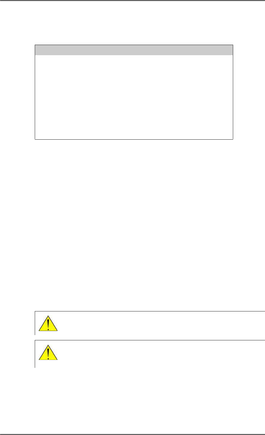
Related documentation
1-2 Chapter 1: About this manual 98-124743-F
1.3 Related documentation
1.4 Precautions: Warnings, Cautions and Notes
Text marked with “Warning”, “Caution”, “Note” or “Important” show the following type of
data:
•Warning: A Warning is an operation or maintenance procedure that, if not obeyed, can
cause injury or death, or jeopardize the flight safety on the aircraft.
•Caution: A Caution is an operation or maintenance procedure that, if not obeyed, can
cause damage to the equipment.
•Note: A Note gives information to help the reader.
•Important: A text marked Important gives information that is important to the user,
e.g. to make the system work properly. This text does not concern damage on
equipment, flight safety nor personal safety.
General precautions
All personnel who operate equipment or do maintenance as specified in this manual must
know and follow the safety precautions. The warnings and cautions that follow apply to all
parts of this manual.
Part number Description
98-130578 AVIATOR 700 User Manual
98-130554 AVIATOR 700 Quick Guide
98-129599 AVIATOR Wireless Handset and Cradle User Manual
98-129600 AVIATOR Wireless Handset and Cradle Installation &
Maintenance Manual
98-132721 Swift64 and H+ Data Service, Supplement to AVIATOR
700 and Aero-HSD+ User Manual (available for
download)
Table 1-1: List of Related Documentation
WARNING! Before using any material, refer to the manufacturers’ material
safety data sheets for safety information. Some materials can be dangerous.
CAUTION! The AVIATOR 700 system contains items that are electrostatic
discharge sensitive. Use approved industry precautions to keep the risk of
damage to a minimum when you touch, remove or insert parts or assemblies.

98-124743-F 2-1
Chapter 2
Introduction to the AVIATOR 700 2
2.1 General description
This Installation manual describes the administrative and technical aspects, features,
functions and components of the AVIATOR 700 system. All comments or
recommendations regarding the installation, acceptance or operation of the system or its
accessories and components should be directed to Cobham SATCOM.
The AVIATOR 700 system is available in two versions:
• AVIATOR 700 approved to RTCA specification DO- 178B level E and DO-254
level E
• AVIATOR 700D approved to RTCA specification DO-178B level D and DO-254
level D.
In general descriptions the nomenclature AVIATOR 700 covers both versions.
Where necessary, the Level D system is specified as AVIATOR 700D.
2.1.1 The AVIATOR 700 system
Important for AVIATOR 700 (Level E)!
The design of the system is not intended to support flight communication for safety
purposes, in particular for Air Traffic Services (ATS) or Aeronautical Operational Control
(AOC), during flight time.
The software used to control the unit operation complies with
RTCA specification DO-178B level E application software.
The firmware used to control the unit operation complies with
RTCA specification DO-254 level E firmware.
The Satellite Data Unit (SDU), the SwiftBroadband Unit (SBU) and the High Power Amplifier
(HPA) must all be level E approved. No mismatch is allowed.
Important for AVIATOR 700D (Level D)!
The design of the system is intended to support flight communication for safety purposes,
including Air Traffic Services (ATS) and Aeronautical Operational Control (AOC), during
flight time.
The software used to control the unit operation complies with
RTCA specification DO-178B level D application software.
The firmware used to control the unit operation complies with
RTCA specification DO-254 level D firmware.
The Satellite Data Unit (SDU), the SwiftBroadband Unit (SBU) and the High Power Amplifier
(HPA) must all be level D approved. No mismatch is allowed.
Note
Important
Important
Important
Important

General description
2-2 Chapter 2: Introduction to the AVIATOR 700 98-124743-F
Non-Safety interfaces for AVIATOR 700 (Level E)
The following interfaces in the AVIATOR 700 system are strictly for non-safety usage:
• Cockpit voice
• ACARS/AFIS/CMU (information and management systems)
• MCDU (Multifunction Control and Display Unit)
Safety interfaces for AVIATOR 700D (Level D)
The following interfaces in the AVIATOR 700D system are approved for safety usage:
• Cockpit voice
• ACARS/AFIS/CMU (information and management systems)
• MCDU (Multifunction Control and Display Unit)
When wiring safety interfaces for voice and data from a unit to cockpit
equipment, you must make sure that you do not wire other interfaces of the
same unit to equipment located in the cabin.
Use another unit for wiring non-safety interfaces to equipment located in the
cabin.
Wiring safety interfaces
Important
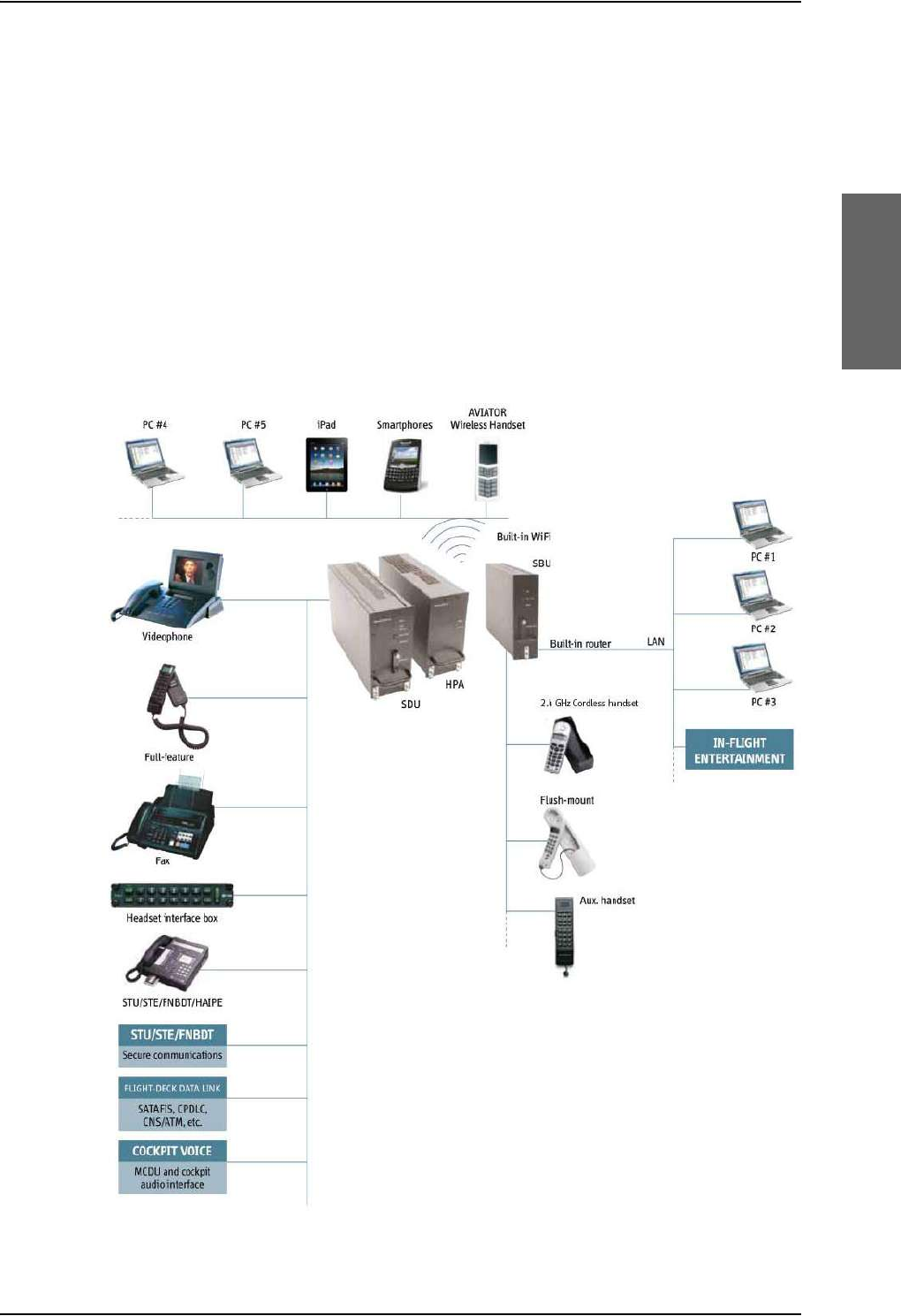
General description
98-124743-F Chapter 2: Introduction to the AVIATOR 700 2-3
Overview of the AVIATOR 700 system
The AVIATOR 700 system offers the classical aeronautical communications services and
the SwiftBroadband service. The TT-5035A Satellite Data Unit (SDU) provides multi-
channel voice and fax and data (Swift 64), while the SwiftBroadband Unit (SBU) provides
access to SwiftBroadband, the aeronautical BGAN service. The SDU is the controlling unit of
the system and the SBU works as a slave unit to the SDU. The data services available
depend on the satellite coverage, read more about satellite coverage at Services on page 2-
4.
The AVIATOR 700 system provides a wide range of user interfaces: several 4-wire and 2-
wire interfaces, ISDN, WLAN and Ethernet interfaces available on the SDU and SBU.
The following drawing shows the AVIATOR 700 cabin installation with connected
communication devices and available options:
Figure 2-1: Communication devices for the AVIATOR 700 system (example)
General description
2-4 Chapter 2: Introduction to the AVIATOR 700 98-124743-F
The basic units in the AVIATOR 700 system are:
•TT-5035A SDU
• TT-5035A-001 Configuration Module (inserted in the SDU)
• TT-5014A HPA
•TT-5040A SBU
• TT-5040A-001 Configuration Module (inserted in the SBU)
The SBU Configuration Module holds permanently installed SIM card, which provides
access to the BGAN network.
• TT-5040A-005 SDU to SBU Software Interface
Services
In the AVIATOR 700 system the classic aeronautical communication services H+ and
Swift64 are combined with the aeronautical BGAN service, SwiftBroadband. To see how the
AVIATOR 700 system handles the communication with Inmarsat’s satellites I4 and I3 that
support these services see the following figure.
Figure 2-2: Satellite coverage of data and voice services
• The SwiftBroadband service provides a channel dedicated to high-speed data using the
BGAN service, operated on Inmarsat’s I4 satellites. SwiftBroadband allows for IP-based
data transfer up to 432 kbps with an HGA (Class 6) and Integrated Services Digital
Network (ISDN @ 64 kbps) circuit-switched data. The SwiftBroadband service may also
be used for speech or 3.1 kHz audio, it accommodates simultaneous voice and data. You
6'8 6%8
,VDWHOOLWH ,VDWHOOLWH
5RXWHU
H[WHUQDOXQLW
,6'1
0'36
(WKHUQHW /$1
6ZLIW%URDGEDQG
&ODVVLFDHURVHUYLFHV
&ODVVLFDHURVHUYLFHV
6ZLIW
9RLFH
$0%(
,3GDWD
4XDOLW\
RI
6HUYLFH
6ZLIW
,6'1
0'36
[+
YRLFH
[
&RFNSLW
,6'1
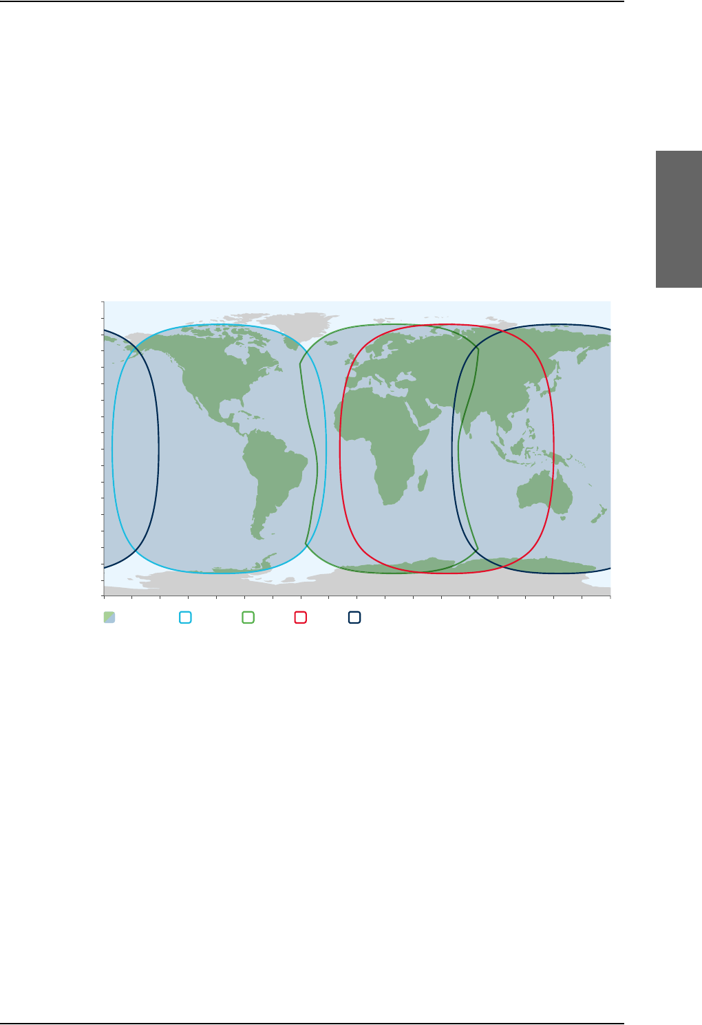
General description
98-124743-F Chapter 2: Introduction to the AVIATOR 700 2-5
can use the AVIATOR 700 cabin installation for IP background data, IP data streaming at
8/16/32/64/128 kbps and X-stream full-channel streaming > 250 kbps, and standard
AMBE 2 voice.
•The Aero-H+ classic services provide two channels for global voice, fax or PC modem
data and one low-speed channel for cockpit communication.
• The Swift64 service provides a 64 kbps backup channel for areas where there is no I4
satellite coverage. The Swift64 channel may operate using ISDN or packet data mode, it
may also be used for speech or for 3.1 kHz audio e.g. for fax.
The following figures show the coverage maps for SwiftBroadband, Swift64 and classic
services available worldwide.
Inmarsat’s I4 satellite coverage (AMER, Alphasat, MEAS, APAC)
Figure 2-3: SwiftBroadband and classic aeronautical services coverage on I4 satellite
0°
10°
20°
30°
40°
50°
60°
70°
80°
90°
10°
20°
30°
40°
50°
60°
70°
80°
90°
0°20°40°60°80°100°120°140°160°180° 20° 40° 60° 80° 100° 120° 140° 160° 180°
Combined I-4 and
Alphasat coverage
I-4 Asia-PacificI-4 Americas Alphasat I-4 MEAS This map depicts Inmarsat’s expectations of coverage following the commercial
introduction of Inmarsat’s fourth L-band region, scheduled for the end of 2015. It does not
represent a guarantee of service. The availability of service at the edge of coverage areas
pXFWXDWHVGHSHQGLQJRQYDULRXVFRQGLWLRQV6ZLIW%URDGEDQGFRYHUDJH'HFHPEHU

Figure 2-4: Swift64 and classic aeronautical services coverage on I3 satellite
General description
2-6 Chapter 2: Introduction to the AVIATOR 700 98-124743-F
Swift64 and Classic aeronautical services coverage (IOR, POR, AORE, AORW)
The maps show Inmarsat's expectations of coverage but do not represent a guarantee of
service. The availability of service at the edge of coverage areas fluctuates depending on
various conditions.
This map depicts Inmarsat’s expectations of coverage, but does
not represent a guarantee of service. The availability of service
DWWKHHGJHRIFRYHUDJHDUHDVpXFWXDWHVGHSHQGLQJRQYDULRXV
conditions. Classic Aero and Swift 64 coverage December 2015.
0°
10°
20°
30°
40°
50°
60°
70°
80°
90°
10°
20°
30°
40°
50°
60°
70°
80°
0°20°40°60°80°100°120°140°160°180° 20° 40° 60° 80° 100° 120° 140° 160° 180°
Atlantic Ocean Region-East
Aero H services are provided in the
full footprint of the global beams
Swift 64, Aero H+,
Aero I coverage
Pacific Ocean Region Atlantic Ocean Region-West
Indian Ocean Region
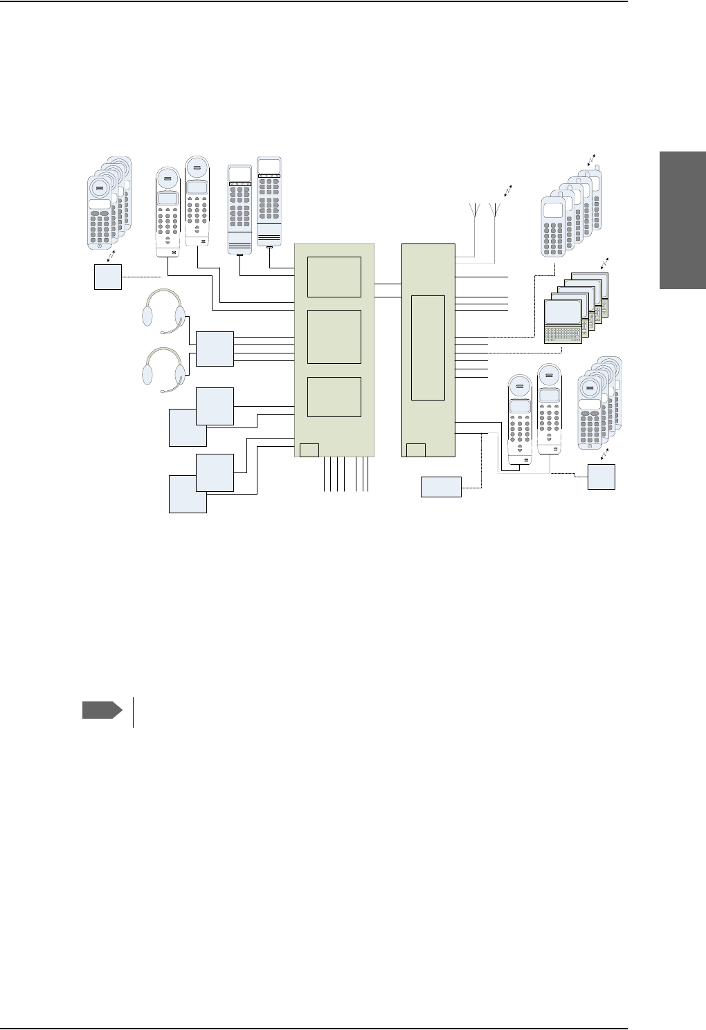
General description
98-124743-F Chapter 2: Introduction to the AVIATOR 700 2-7
PBX telephone exchange
The AVIATOR 700 system has two built-in PBX units: One in the SDU and one in the SBU,
making the AVIATOR 700 capable of connecting in total four 4-wire handsets and four 2-
wire devices.
Figure 2-5: PBX functionality in SDU and SBU
The built-in PBX of the SDU connects up to four 4-wire handsets, two direct 2-wire POTS
interfaces for faxes, PC modems, auxiliary phones, headset interface boxes etc. and one
ISDN interface for ISDN phones, fax machines or Secure communication.
The built-in PBX of the SBU connects two direct 2-wire POTS interfaces for faxes, auxiliary
phones, headset interface boxes etc., as well as an ISDN interface for ISDN phones, fax
machines or Secure communication. The built-in PBX of the SBU can route VoIP calls that
are terminated in the SIP server of the SBU.
There is no routing between the PBX of the SDU and the PBX of the SBU.
Configuration Modules (CM)
There are two Configuration Modules in the AVIATOR 700 system:
• SDU Configuration Module
• SBU Configuration Module
The Configuration Module (CM) for the SDU contains system and user settings for easy
replacement of the Satellite Data Unit (SDU). To access these settings use the Aero-SDU
Configuration Program. For further information on the configuration program, see
Configure the basic system on page 6-1. Different layers of write protection protect the
CM contents; this includes hardware protection of installation settings and optional pin
code protection of user data. The SDU Configuration Module is designed as a “plug-in”
Note
,6'1
/$1
/$1
/$1
/$1
/$1
:LUH
:/$1%
:/$1$
56
6ZLIW%URDGEDQG8QLW6%8
0&8
$HUR+6'6'8
0&8
$),6$&$56
$),6$&$56
0&'8:6&,
0&'8:6&,
&RFNSLW9RLFH$QDORJXH
&RFNSLW9RLFH$QDORJXH
&RFNSLW9RLFH'LVFUHWHV
&RFNSLW9RLFH'LVFUHWHV
:LUH+DQGVHW
:LUH+DQGVHW
$QQXQFLDWRU([W5LQJHU
&RQILJ
0RGXOH
&RQILJ
0RGXOH
:LUH,QWHUIDFH
:LUH,QWHUIDFH
+
&&KDQQHO
9RLFH)D['DWD
+
357
&RFNSLW'DWD
+
&&KDQQHO
9RLFH)D['DWD
:LUHOHVV/$1
$QWHQQDV
([LVWLQJ:+DQGVHWV
FDQEHUHXVHG
:LUH
)$;
77$
:+DQGVHW
7KUDQH7KUDQH
77$
:+DQGVHW
7KUDQH7KUDQH
$XGLR
0DQDJHPHQW
6\VWHP
&KDQQHO
0&'8
($6\&RFNSLW
0&'8
($6\&RFNSLW
)06&08
)06&08
3&
:LUHOHVV/$1
3&¶VDQGKDQGVHWV
FDQDOVREHZLUHG
$QQXQFLDWRU+68)DLOXUH
$QQXQFLDWRU+68/RJHG2Q
6%8HQDEOH
,56$+56
,56$+56
:R:
&DOO$QQXQFLDWRU
)$;$QQXQFLDWRU
6HUYLFH$YDLODEOH
&KLPH
:LUH
6,*0$
6,*0$
,3:/$1
+DQGVHW
,3:/$1
+DQGVHW
,3:/$1
+DQGVHW
,3:/$1
+DQGVHW
,3:/$1
+DQGVHW
+DQGWHWV
:LUHOHVV/$1
/$3723
3&
/$3723
3&
/$3723
3&
/$3723
3&
:/$1
/$37233&
,&*
&RUGOHVV
%DVH
VWDWLRQ
:LUH,QWHUIDFH
,&*
&RUGOHVV
%DVH
VWDWLRQ
6,*0$
6,*0$
,&*
&RUGOHVV
,&*
&RUGOHVV
,&*
&RUGOHVV
,&*
&RUGOHVV
,&*
&RUGOHVV
,&*
&RUGOHVV
,&*
&RUGOHVV
,&*
&RUGOHVV
6ZLIW
%URDGEDQG
0RGXOH
/$1

General description
2-8 Chapter 2: Introduction to the AVIATOR 700 98-124743-F
module for the SDU, making it easier to replace the SDU while retaining all system and user
settings.
The Configuration Module (CM) for the SBU is inserted in the SBU and holds system and
user settings for easy replacement of the SwiftBroadband Unit (SBU). Different layers of
write protection protect the CM contents; this includes hardware protection of installation
settings and optional pin code protection of user data. It is designed as a “plug-in” module
for the SBU, so the SBU can be replaced while retaining all SBU and user settings. The SBU
CM contains a permanently built-in SIM card for access to the SwiftBroadband services.
Configuration of the AVIATOR 700 system
The AVIATOR 700 system is configured with two tools:
• The Aero-SDU Configuration Program to set up and configure the SDU.
• SBU web interface to set up and configure the SBU.
Use the Aero-SDU Configuration Program to access the SDU and antenna settings that
must be configured. The configuration settings are stored in the CM of the SDU. To set up
or change a configuration you must connect a PC to the connector marked Maintenance
on the SDU front plate. For further information how to install the configuration program
see Aero-SDU Configuration Program for the SDU on page 6-2.
Use the built-in web interface of the SBU to access the SBU configuration settings in the
CM of the SBU. A subset of the configuration settings are stored in a write-protected area
of the CM. This subset contains the physical settings for the antenna, cabling and other
external input.
To set up or change the settings of the write-protected area you must connect a PC to the
connector marked Maintenance on the SBU front plate. You can view all SBU settings
from any LAN or WLAN interface. For further information on the web interface, see SBU
Configuration tasks on page 6-12.
The TT-5040A-005 SDU to SBU Software Interface is part of the basic AVIATOR 700
system. It activates the software code that enables the interface between the SDU and the
SBU. The SDU to SBU Software Interface is pre-configured at the factory when ordering the
basic AVIATOR 700 system.
Satcom antenna systems
The AVIATOR 700 system can be used with a wide range of satcom antennas. An AVIATOR
700 system must only be used with satcom antennas that have received type approval by
Inmarsat.
The following ARINC 781 compatible antennas from Cobham SATCOM have received
Inmarsat type approval:
• HGA-6000
•HGA-6500
•HGA-7000
•HGA-7001

General description
98-124743-F Chapter 2: Introduction to the AVIATOR 700 2-9
Built-in router and Wireless (WLAN) option
The AVIATOR 700 system offers a built-in router as an option. With this option multiple
users and applications can use the system simultaneously. Without this option only the first
device that connects to the SBU will be allowed on the Internet.
The system also offers a built-in WLAN option for wireless communication devices and a
WLAN antenna approved for aeronautical use. This includes full WLAN routing
functionality.
If ordered, this option is enabled in the AVIATOR 700 from the factory. If these options are
not included from the start, the system can be upgraded at a later stage. Then you receive
the FLEX key for the purchased options and enter it in the AVIATOR 700 web interface.
Built-in Multi-voice option1
The AVIATOR 700 system offers a built-in Multi-voice option. With this option multiple
calls can be made to and from the system simultaneously. Normally, the BGAN system only
supports one call at a time. With the built-in, optional Multi-voice service enabled in your
system, you can make multiple calls. The maximum number of concurrent calls is 1+ 8. If
ordered, this option is enabled in the AVIATOR 700 from the factory. If this option is not
included from the start, the system can be upgraded at a later stage. Then you receive the
FLEX key for the purchased options and enter it in the AVIATOR 700 web interface.
You must have Multi-voice in your airtime subscription, AVIATOR Wireless
Handset software version minimum 1.03 and SBU software version minimum
AVIATOR 700 (Level E): 1.07, AVIATOR 700D (Level D): 2.01, in order to support
the Multi-voice function.
For information on how to set up Multi-voice, see Multi-voice (option) on page 6-88.
Interface to MCDU
The Multifunction Control and Display Unit (MCDU) can be used to control and operate the
SATCOM equipment from the cockpit. The MCDU has the same menus and functions as the
4-wire cabin handsets. Using the cockpit voice interface which connects to the pilot
headset via the cockpit Audio Management System the pilot can then make satcom calls
from the cockpit without using a handset. He can also read status messages of the
AVIATOR 700 system in the MCDU display.
2.1.2 AVIATOR 700 features
The AVIATOR 700 system has the following features:
Unique multi-channel solution, combining the Inmarsat Aero-H+, Swift64 and
SwiftBroadband services with the following channels available:
• one spot beam SwiftBroadband channel, providing access to the BGAN system with
data rates up to 432 kbps.
• one spot beam High Speed Data (HSD) channel (Backup ISDN)
1. Supported from software version 1.07 for AVIATOR 700 (Level E) and 2.01 for AVIATOR 700D (Level
D).
Note

General description
2-10 Chapter 2: Introduction to the AVIATOR 700 98-124743-F
• two CS (circuit switched) mode H+ channels for voice, G3 fax or PC modem data for
global or spot beam operation.
•one global H
+ packet data channel for cockpit communications
Full duplex, single or multi-user.
Automatic satellite selection.
Built-in PBX in the SDU interfacing to four 4-wire and two 2-wire connections and one
ISDN connection.
Built-in PBX in the SBU interfacing to two 2-wire connections, one ISDN interface and
WLAN in the SBU, and integrated SIP server for VOIP telephony.
Standard voice.
3.1 kHz audio for modems, G3 fax, 14.4 kbps high quality voice etc.
ISDN voice for Secure communication, G4 fax etc.
ISDN data for video conferences etc.
Built-in Router option in the SBU with DHCP, NAT for six Ethernet interfaces.
Built-in Wireless option (WLAN) IEEE 802.11 b/g in the SBU.
Built-in Multi-voice option, up to 1+8 concurrent calls
Access to built-in web interface for daily use using SBU LAN and WLAN.
Aero-SDU Configuration Program
Built-in web interface for SBU configuration using the Maintenance connector on the
SBU front plate.
ARINC 741 and ARINC 781 antenna compatibility
HGA-7000 antenna compatibility

Application
98-124743-F Chapter 2: Introduction to the AVIATOR 700 2-11
2.2 Application
2.2.1 Minimum system
A minimum working system has at least:
•one TT-5035A SDU
•one TT-5035A-001 CM
• one TT-5014A HPA
• one TT-5040A SBU
• one TT-5040A-001 CM
• one TT-5040A-005 SDU to SBU Software interface
•one TT-5038A-002 Tx Coupler
•one TT-5038A-003 Rx Power Splitter
• one handset and cradle, e.g. a TT-5620A 4-Wire Handset and a TT-5622A 4-Wire Cradle
(optional)
• one antenna system with TT-5013A DNLA type F. As antenna system, use either an
ARINC 741 or ARINC 781 antenna system.
The minimum wiring required for an AVIATOR 700 system is described in the section
Minimum system drawing on page 5-3.
2.2.2 Part numbers
Applicable model- and part numbers
This installation manual is for the AVIATOR 700 system and is applicable to the model and
part numbers below:
Part number Model number Description
405035A TT-5035A Satellite Data Unit (SDU) [without CM] AVIATOR
700
405035A-THD TT-5035A Satellite Data Unit (SDU) [without CM] AVIATOR
700D
405035A-001 TT-5035A-001 Configuration Module (CM) for SDU for AVIATOR
700 and AVIATOR 700D
405040A TT-5040A SwiftBroadband Unit (SBU) [without CM] for
AVIATOR 700
405040A-THD TT-5040A SwiftBroadband Unit (SBU) [without CM] for
AVIATOR 700D
Table 2-1: Model and part numbers for the AVIATOR 700 system (T&T units)

Application
2-12 Chapter 2: Introduction to the AVIATOR 700 98-124743-F
405040A-001 TT-5040A-001 Configuration Module (CM) for SBU (no key and no
options)
405040A-002 TT-5040A-002 Built-in Router option
405040A-003 TT-5040A-003 Built-in Wireless option
405040A-004 TT-5040A-004 WLAN Antenna, optional (2 pieces recommended)
405040A-010 TT-5040A-010 Built-in Multi-voice option
405040A-005 TT-5040A-005 SDU to SBU Software Interface
405040A-835 TT-5040A-835 405040A-001 CM, preprogrammed with:
405040A-005, SDU to SBU Software Interface
405040A-825 TT-5040A-825 405040A-001 CM, preprogrammed with:
405040A-005, SDU to SBU Software Interface
405040A-002, Built-in Router Option
405040A-815 TT-5040A-815 405040A-001 CM, preprogrammed with:
405040A-005, SDU to SBU Software Interface
405040A-003, Built-in WiFi Option
405040A-805 TT-5040A-805 405040A-001 CM, preprogrammed with:
405040A-005, SDU to SBU Software Interface
405040A-002, Built-in Router Option
405040A-003, Built-in WiFi Option
405038A-002 TT-5038A-002 Tx Coupler
405038A-003 TT-5038A-003 Rx Power Splitter
405014A TT-5014A High Power Amplifier (HPA) AVIATOR 700
405014A-THD TT-5014A High Power Amplifier (HPA) AVIATOR 700D
405013A TT-5013A DLNA Type F
405620A-THW TT-5620A 4-Wire Handset (white)
405620A-THR TT-5620A 4-Wire Handset (black)
405622A-THW TT-5622A 4-Wire Cradle (white)
405622A-THR TT-5622A 4-Wire Cradle (black)
405621B-THW TT-5621B 2-Wire Handset (white)
405621B-THR TT-5621B 2-Wire Handset (black)
405622B-THW TT-5622B 2-Wire Cradle (white)
Part number Model number Description
Table 2-1: Model and part numbers for the AVIATOR 700 system (T&T units) (Continued)
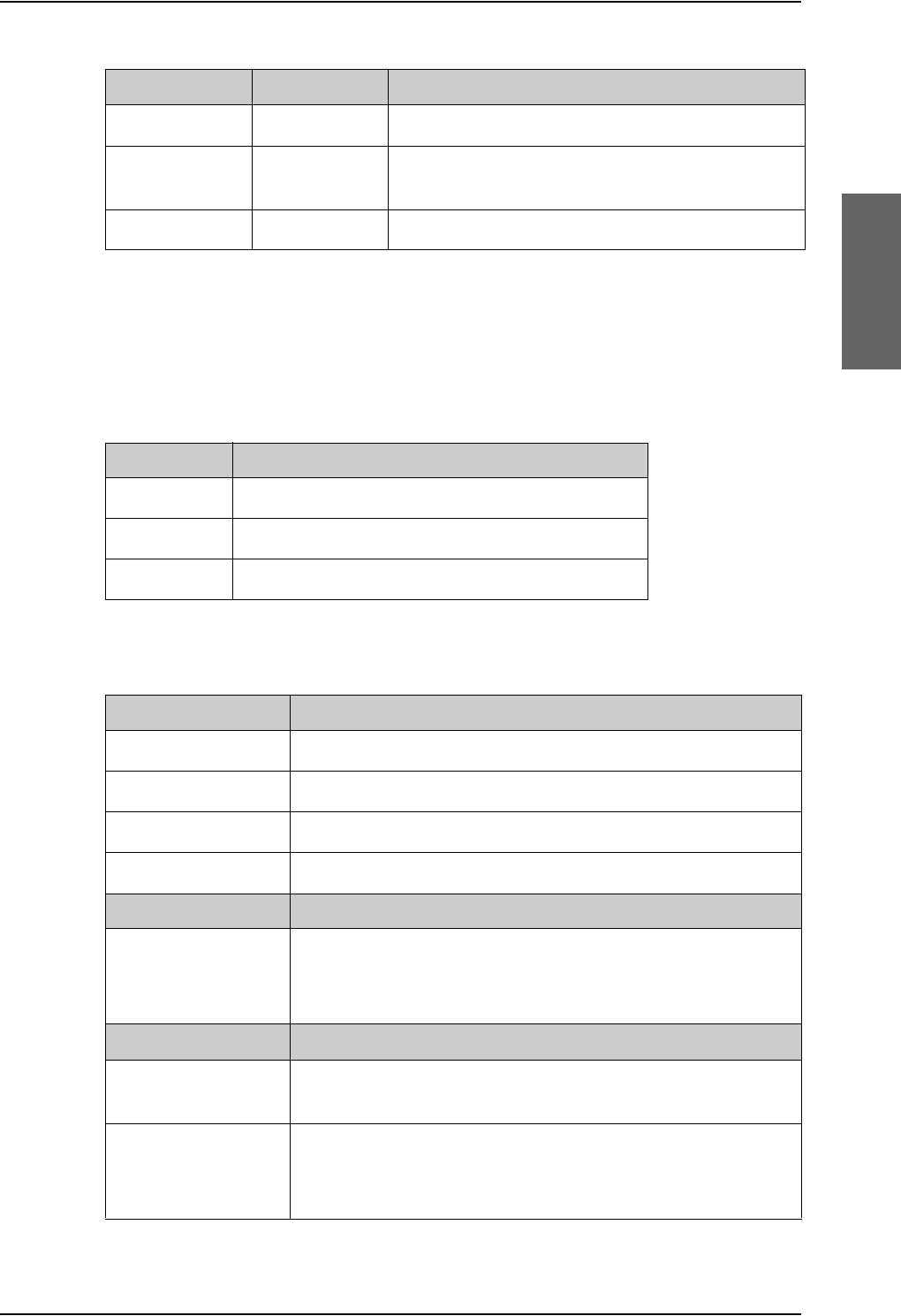
Application
98-124743-F Chapter 2: Introduction to the AVIATOR 700 2-13
The Satellite Data Unit (SDU), the SwiftBroadband Unit (SBU) and the High Power Amplifier
(HPA) must all be level E or level D approved. No mismatch is allowed.
Circuit breakers
Trays and connectors
405622B-THR TT-5622B 2-Wire Cradle (black)
TT 37-112940 Maintenance Cable
(SDU Front Connector Maintenance to PC)
TT 83-119958 CD with Aero-SDU Configuration Program
Part number Model number Description
Table 2-1: Model and part numbers for the AVIATOR 700 system (T&T units) (Continued)
Part number Recommended aircraft circuit breakers
2TC2-4 Klixon 2TC series, 4 A current rating (SDU)
2TC2-7.5 Klixon 2TC series, 7.5 A current rating (SBU)
2TC2-20 Klixon 2TC series, 20 A current rating (HPA)
Table 2-2: Part numbers for Klixon circuit breakers
Part number Approved tray
PO299-101 ECS Tray Assembly 1/4-size ATR (for SBU)
MT4-2346-101 EMTEQ Tray Assembly 1/4-size ATR (for SBU)
200-86686-101 ECS Tray Assembly 3/8-size ATR (for HPA and SDU)
MT4-3300-110 EMTEQ Tray Assembly 3/8-size ATR (for HPA and SDU)
Part Number Required Connector Kit for SDU Tray
DPX2NA-67322-605
(old number:
DPX2NA-67322-463)
ITT Cannon Connector, Dual Plug, contact arrangement
top:33C4, bottom:106.
Part Number Required Connector Kit for HPA Tray
616 697 173 RADIALL Dual Plug Connector, contact arrangement top: MC2,
bottom: 32C2.
DPX2NA-67322-606
(old number:
DPX2NA-67322-500)
Required Connector Kit for SBU tray: ITT Cannon Connector,
Dual Plug, contact arrangement top: 33C4, bottom: 33C4.
Table 2-3: Part numbers for trays and connectors
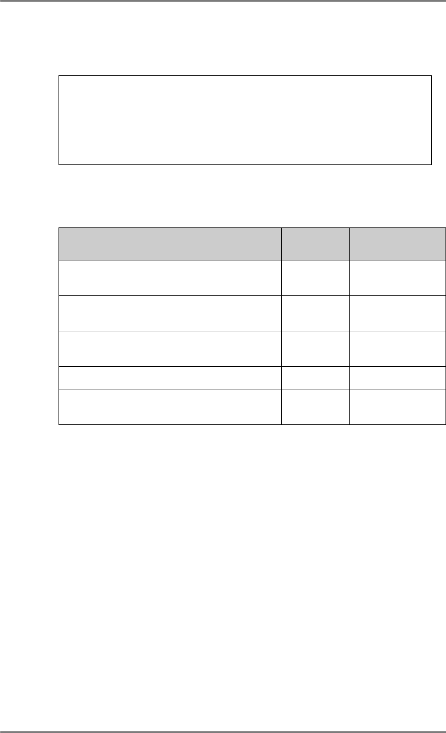
Application
2-14 Chapter 2: Introduction to the AVIATOR 700 98-124743-F
Installation kits
For installation kits for the AVIATOR 700 system contact:
Table 2-4: Installation kits, contact information
ECS offers two installation kits, one for AVIATOR 700 (ECS part number: 120-14973-101)
and one for the SBU (ECS part number: 120-14973-102).
ECS, a Carlisle IT company, USA
Phone (Franklin, WI): +1 800-327-9473
Phone (Kent, WA): +1 800-227-5953
E-mail: sales@CarlisleIT.com
Home page: www.CarlisleIT.com
EMTEQ (B/E Aerospace)
Home page: www.emteq.com
Contact info: www.emteq.com/contact-
us.php
Item in installation kit AVIATOR 700 Upgrade from HSD+
to AVIATOR 700
ARINC connector, SBU
(DPX2NA-67322-500 or DPX2NA-67322-606)
11
Tray Assembly, SBU, 1/4-size ATR W/DPX2
(P0299-101)
11
ARINC connector, SDU
(DPX2NA-67322-463 or DPX2NA-67322-605)
1—
ARINC connector, HPA (616697173) 1 —
Tray Assembly, HPA and SDU, 3/8-size ATR
W/DPX2 (200-86686-101)
2—
Table 2-5: Basic installation kits from ECS

System block diagrams
98-124743-F Chapter 2: Introduction to the AVIATOR 700 2-15
2.3 System block diagrams
2.3.1 Introduction
Overview
The following block diagrams and the wiring diagrams in section 5.3.3 show examples of
satcom antennas that can be connected to the AVIATOR 700 system.
In order to use the satcom antenna with the AVIATOR 700 system, the specific antenna
type and the AVIATOR 700 system must be Type Approved by Inmarsat as a combined
system. AVIATOR 700 systems will be Inmarsat Type Approved with more antennas as
requested by market requirements. Contact your Cobham SATCOM sales/support
representative for the latest status on Inmarsat Type Approvals for satcom antennas for the
AVIATOR 700 system.
The following block diagrams show the basic system component interconnection.
The first diagrams show the wiring differences according to antenna choice and antenna
steering source. The following system block diagrams show the user interfaces and the
system interface to the MagnaStar system PBX communication.
Selection of DLNA
Important
Whether the antenna system is ARINC 741 or ARINC 781, the DLNA must
be ARINC 781 Type F compliant and contain extra TX-filtering for
protection of the GNSS and Iridium band.
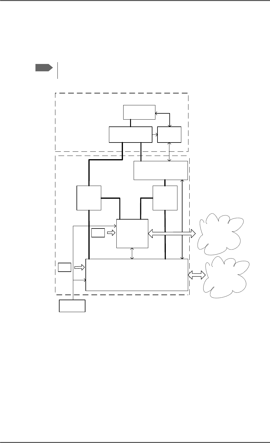
System block diagrams
2-16 Chapter 2: Introduction to the AVIATOR 700 98-124743-F
2.3.2 ARINC 741 compatible High Gain Antenna
The AVIATOR 700 system supports ARINC 741 compatible antenna systems, such as a
HGA-6000 antenna or an HGA-7000 antenna with an HGA-7000 BSU.
Note
In an AVIATOR 700 system, there are extra requirements to the DLNA. For further
information, see Selection of DLNA on page 2-15.
Figure 2-6: System Configuration with ARINC 741 Compatible HGA and IRS
$5,1&
$QWHQQD
$&8
%68
+3$
$5,1&$QWHQQD6XEV\VWHP
'/1$
$5,1&7\SH)
FRPSDWLEOH
6'8
,56
&0
8VHU
,QWHUIDFHV
7[5[
6%8 8VHU
,QWHUIDFHV
7[5[
5[
3RZHU
6SOLWWHU
7[
&RXSOHU
&0
$9,$725
6\VWHP
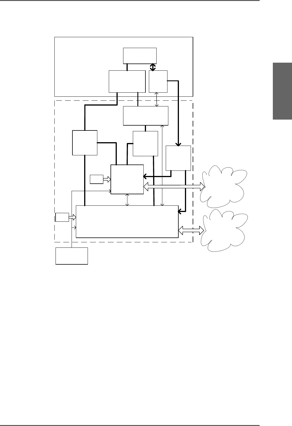
System block diagrams
98-124743-F Chapter 2: Introduction to the AVIATOR 700 2-17
You can also configure the system with AHRS/GPS.
Figure 2-7: System Configuration with HGA 7000
+*$
$QWHQQD
+3$
+*$$QWHQQD6XEV\VWHP
$5,1&
7\SH)
'/1$
6'8
,56
$+56>@
&0
8VHU
,QWHUIDFHV
7[
5[
6%8 8VHU
,QWHUIDFHV
7[
5[
5[
3RZHU
6SOLWWHU
7[
&RXSOHU
&0
$9,$725
6\VWHP
*36
>@
>@$+56FDQRQO\EHXVHGZKHQ*36VLJQDOLVURXWHGIURPWKH%68
%68
*36
3RZHU
6SOLWWHU
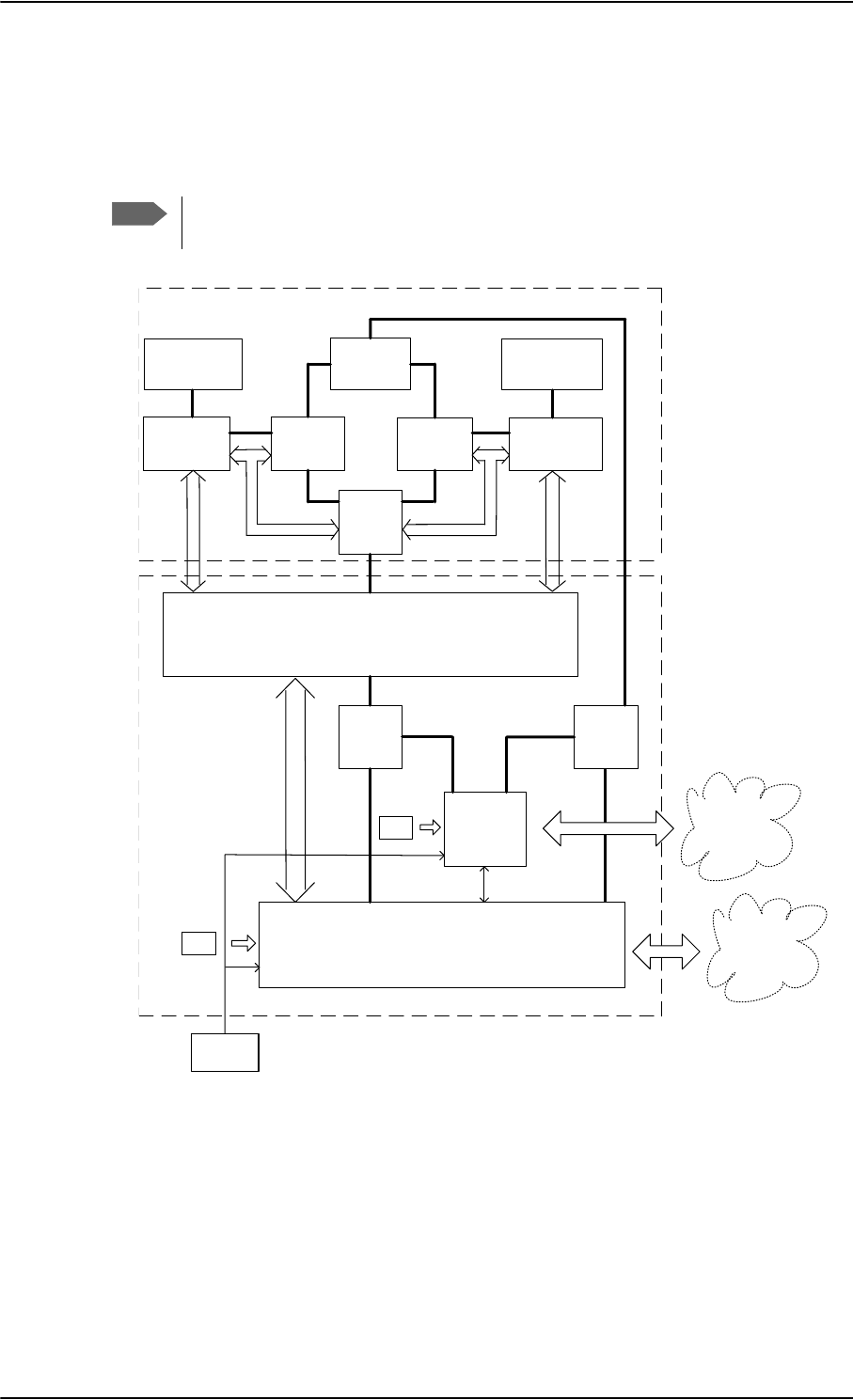
System block diagrams
2-18 Chapter 2: Introduction to the AVIATOR 700 98-124743-F
2.3.3 Dual side panel antenna system
An ARINC 741 dual side panel antenna system may be installed, in order to improve the
view to the satellite.
Note
In an AVIATOR 700 system, there are extra requirements to the DLNA. For further
information, see Selection of DLNA on page 2-15.
Figure 2-8: System Configuration with Dual Side Panel Antenna System & IRS
+*$3RUW
+3$
'/1$
3RUW
6'8
,56
8VHU
,QWHUIDFHV
+35
'/1$
67%2
%68
3RUW
%68
67%2
+*$
67%2
&RPELQHU
$5,1&'XDO6LGH3DQHO$QWHQQD6\VWHP
7[
5[
6%8
7[
&RXSOHU
5[
3RZHU
6SOLWWHU
&0
7[
7[
7[
5[
5[
8VHU
,QWHUIDFHV
&0
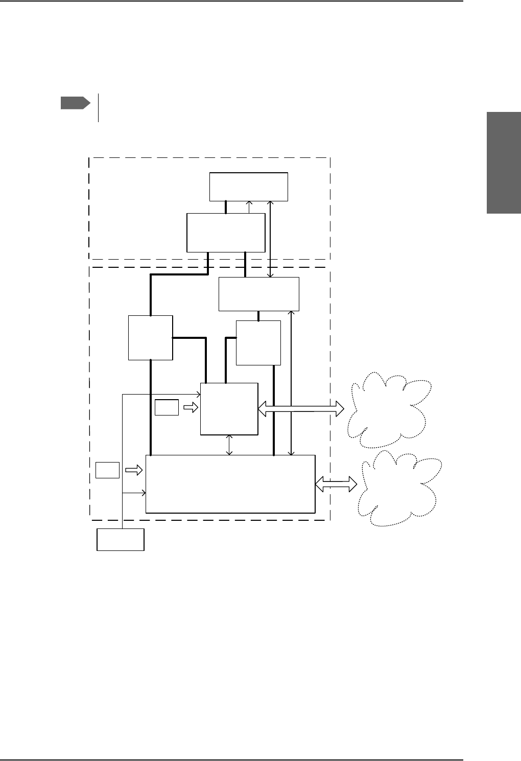
System block diagrams
98-124743-F Chapter 2: Introduction to the AVIATOR 700 2-19
2.3.4 ARINC 781 compatible High Gain Antenna
The AVIATOR 700 system supports ARINC 781 compatible antenna systems.
Figure 2-9: System Configuration with ARINC 781 Compatible HGA with IRS
You can also configure the system with AHRS/GPS.
Note
In an AVIATOR 700 system, there are extra requirements to the DLNA. For further
information, see Selection of DLNA on page 5-17.
$5,1&
$QWHQQD
+3$
'/1$
$5,1&7\SH)
FRPSDWLEOH
6'8
&0
8VHU
,QWHUIDFHV
7[
5[
6%8 8VHU
,QWHUIDFHV
7[5[
5[
3RZHU
6SOLWWHU
7[
&RXSOHU
&0
$9,$725
6\VWHP
,56
$5,1&$QWHQQD6XEV\VWHP

System block diagrams
2-20 Chapter 2: Introduction to the AVIATOR 700 98-124743-F
2.3.5 User interfaces
The AVIATOR 700 system has the following user interfaces:
Table 2-6: User interfaces, overview
Interfaces SDU SBU
4-wire PBX interfaces
This interface can be used e.g. for the TT-5620A 4-Wire Handset and
TT-5622A 4-Wire Cradle.
For additional information on the use of the 4-wire interfaces see
Wiring telephone systems on page 5-47.
4 0
2-wire POTS interface
This interface can be used for the TT-5621B 2-Wire Handset and TT-
5622B 2-Wire Cradle or other POTS handsets.
The TT-5622B 2-Wire Cradle has an RJ11 connector to which
additional 2-wire terminals can be connected, e.g. for fax or modem
data.
2 2
10/100BaseT Ethernet interfaces for connecting IP equipment. Note
that the SBU has a Built-in Router option.
The SBU has an additional Ethernet interface for system configuration
(Maintenance connector on the SBU front plate, not shown in the
following figure)
1 6
Built-in Wireless Option with two WLAN antenna interfaces for
diversity operation to connect WiFi-enabled equipment like lap tops,
Smart phones or VOIP handsets.
0 1
Euro ISDN S-bus interface for PC, Fax or STE) 1 1a
a. Without DC power support.
ARINC 429 interfaces for e.g. ACARS/AFIS/CMU (2 x) or MCDU (2 x). 4 0
Discrete outputs for annunciators 3 4
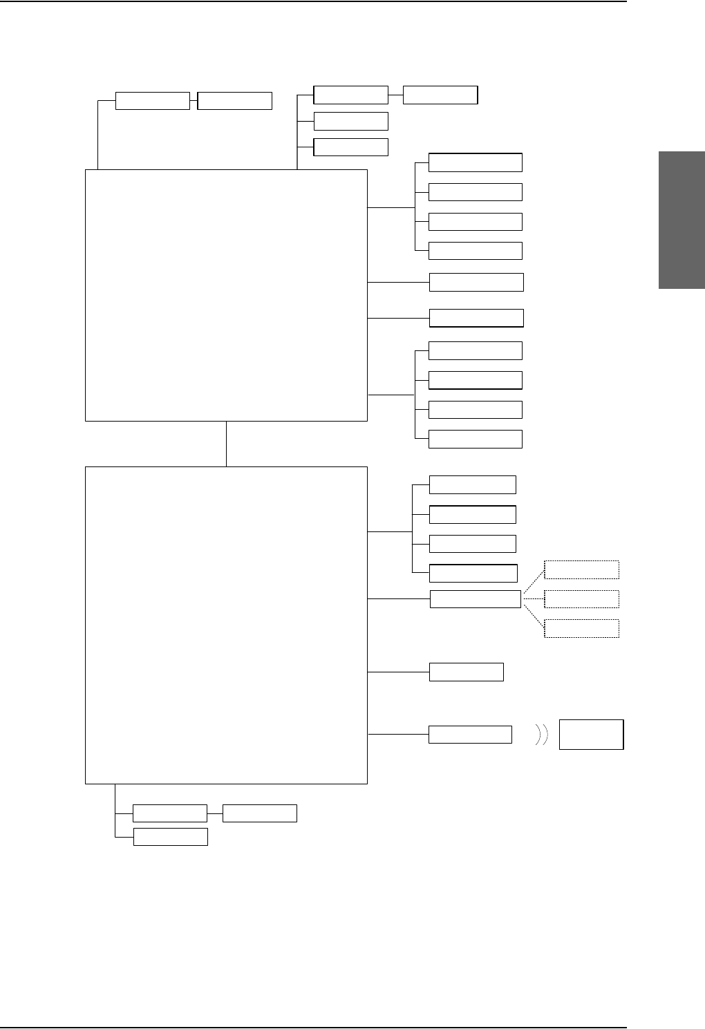
System block diagrams
98-124743-F Chapter 2: Introduction to the AVIATOR 700 2-21
The following figure shows most of the possible user interfaces.
Figure 2-10: System Configuration showing the user interfaces
77$6'8
*)D[
678
&08
$),6
$&$56
0&'8
ZLUH
5-
$5,1&
:&UDGOH
ZLUH
:+DQGVHW
:&UDGOH :+DQGVHW
$QQXQFLDWRUV
'LVFUHWH
2XWSXWV
77$6%8
,3(TXLSPHQW
,6'1
(WKHUQHW
$QQXQFLDWRUV
'LVFUHWH
2XWSXWV
*)D[
:&UDGOH :+DQGVHW
56
,6'1
:/$1DQWHQQD :LUHOHVV,3
HTXLSPHQW
ZLUH
5-
:/$1
56
0'36,RQO\
,6'1SKRQH
*)D[
3&5RXWHU
9LGHRSKRQH
,6'1SKRQH
*)D[,RQO\
3&5RXWHU,RQO\
9LGHRSKRQH,RQO\
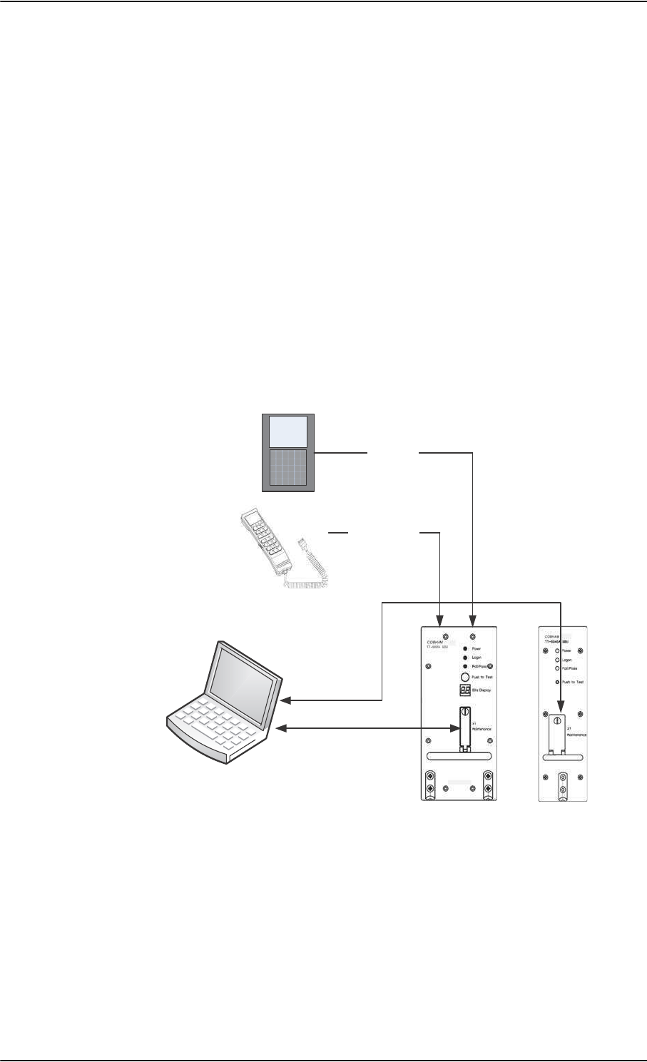
Operation overview
2-22 Chapter 2: Introduction to the AVIATOR 700 98-124743-F
2.4 Operation overview
2.4.1 Configuration
There are two configuration tools for the AVIATOR 700 system:
• Aero-SDU Configuration Program for the SDU
The configuration tool for the SDU is the Aero-SDU Configuration Program. It is
launched from a standard PC connected to the front connector of the SDU (RS232)
with the maintenance cable (see TT 37-112940 maintenance cable for front
connector on SDU and PC on page 5-78). For further information, see Configure the
basic system on page 6-1.
• Web interface for the SBU
The configuration tool for the SBU is the built-in web interface, which can be accessed
from a standard PC connected to the Maintenance connector of the SBU. Note that the
configuration settings can only be accessed from the Maintenance connector
(Ethernet) on the front of the SBU. For further information, see SBU Configuration
tasks on page 6-12.
2.4.2 Operation
The core components of the AVIATOR 700 System are the SDU with the classic aero
services and the SBU providing SwiftBroadband services. These two units share the same
satcom antenna and HPA. When installing the system you must bear in mind at which unit
the handsets and PC equipment are connected, so you prepare the installation for the
future use of various handsets and computers in the cabin.
Figure 2-11: Configuration of the SDU and SBU, overview
3&ZLWKFRQILJXUDWLRQSURJUDP
DQGZHEEURZVHU
0DLQWHQDQFHFDEOH
56
/$1FDEOH
:LUH+DQGVHW
0&'8
$5,1&
:LUHLQWHUIDFH
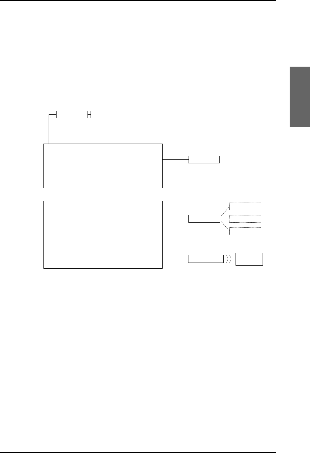
Operation overview
98-124743-F Chapter 2: Introduction to the AVIATOR 700 2-23
You can operate the AVIATOR 700 System from several user interfaces:
• A 4-Wire Handset connected to the SDU. The display and keypad of the handset give
access to the menu system of the SDU.
• The MCDU connected to the SDU. The display and keys of the MCDU give access to a
menu system to control the SDU.
• The web interface of the SBU. It is used to for Internet access, e-mail, IP streaming and
FTP services. It gives also access the SBU phone book, call log and SBU settings. used for
daily operation of the SBU. The settings can be accessed from any of the LAN interfaces,
including WLAN.
Figure 2-12: Interfaces for operating the AVIATOR 700 system
Refer to the AVIATOR 700 User Manual for detailed operating procedures. The AVIATOR
700 User Manual introduces and explains system capabilities and features, handset controls
and functions, placing and receiving calls, accessing the Internet, streaming sessions and
use of the menu system.
77$6'8
0&'8
$5,1&
ZLUH
:&UDGOH :+DQGVHW
77$6%8
,3(TXLSPHQW
(WKHUQHW
:/$1DQWHQQD :LUHOHVV,3
HTXLSPHQW
:/$1
56

Operation overview
2-24 Chapter 2: Introduction to the AVIATOR 700 98-124743-F

98-124743-F 3-1
Chapter 3
Equipment drawings 3
3.1 Introduction
The following pages show copies of outline drawings of important system units relevant for
an installation.
For equipment drawings of the AVIATOR Wireless Handset and Cradle see
AVIATOR Wireless Handset and Cradle Installation & Maintenance Manual (98-
129600).
Important
The drawings in this manual are for reference only. If you have access to the
partner platform Cobham SYNC, you can get copies of the outline drawings
at: https://sync.cobham.com/satcom/support/downloads. You can download
the drawings as PDF files. There are also 3D models of selected units.
Note
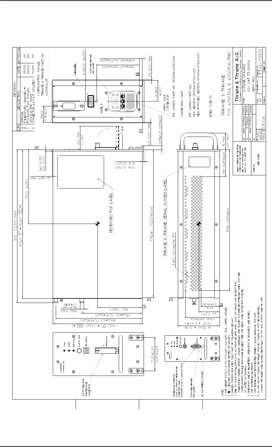
TT-5035A Satellite Data Unit
3-2 Chapter 3: Equipment drawings 98-124743-F
3.2 TT-5035A Satellite Data Unit
Figure 3-1: Outline Drawing: Satellite Data Unit
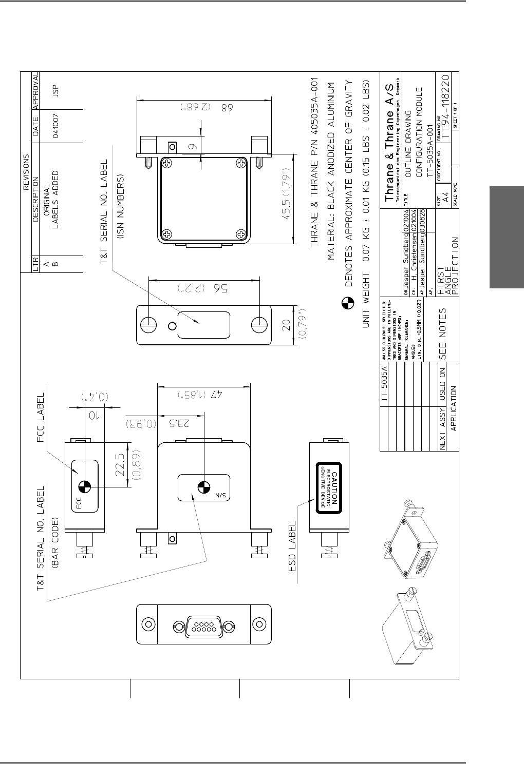
TT-5035A Satellite Data Unit
98-124743-F Chapter 3: Equipment drawings 3-3
3.2.1 TT-5035A-001 Configuration Module (inserted in the SDU)
Figure 3-2: Outline Drawing: Configuration Module
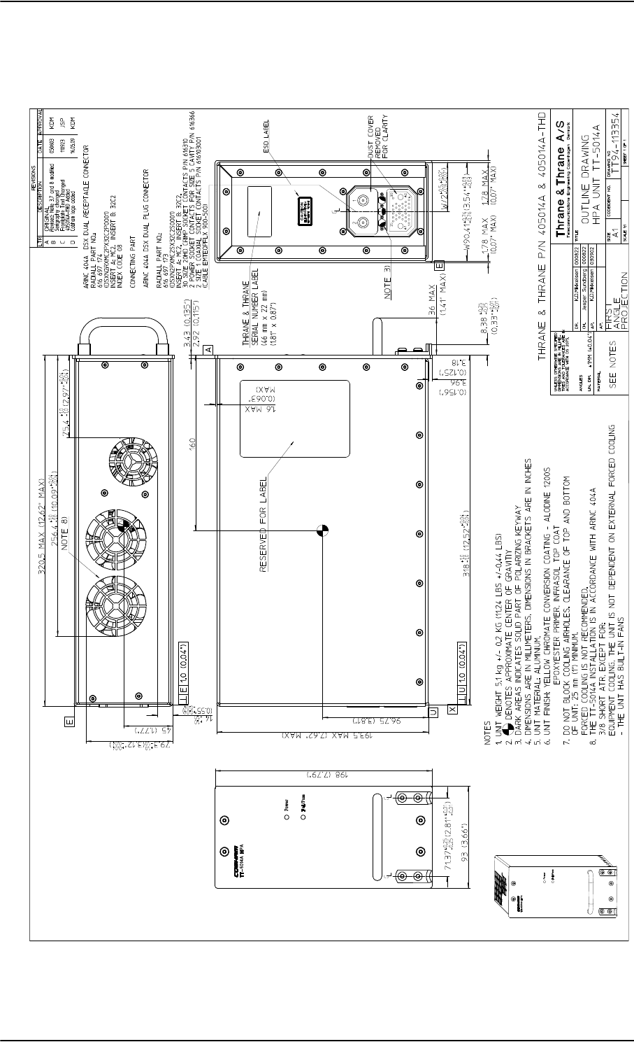
TT-5014A High Power Amplifier
3-4 Chapter 3: Equipment drawings 98-124743-F
3.3 TT-5014A High Power Amplifier
Figure 3-3: Outline Drawing: High Power Amplifier
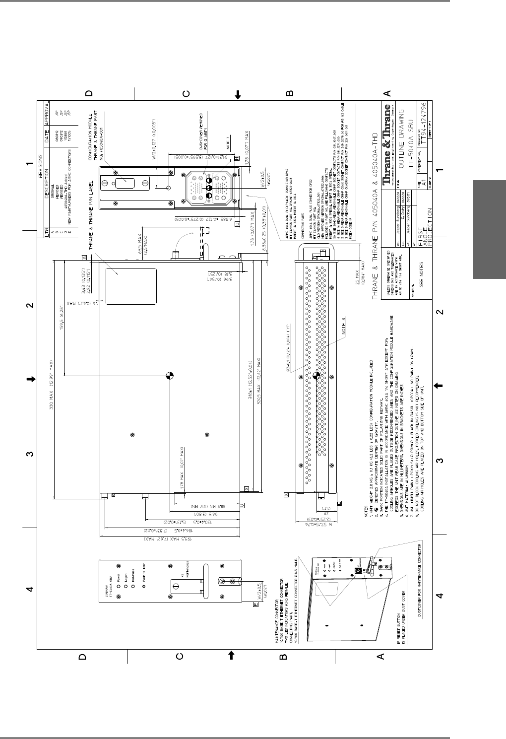
TT-5040A SBU
98-124743-F Chapter 3: Equipment drawings 3-5
3.4 TT-5040A SBU
Figure 3-4: Outline drawing: TT-5040A SBU
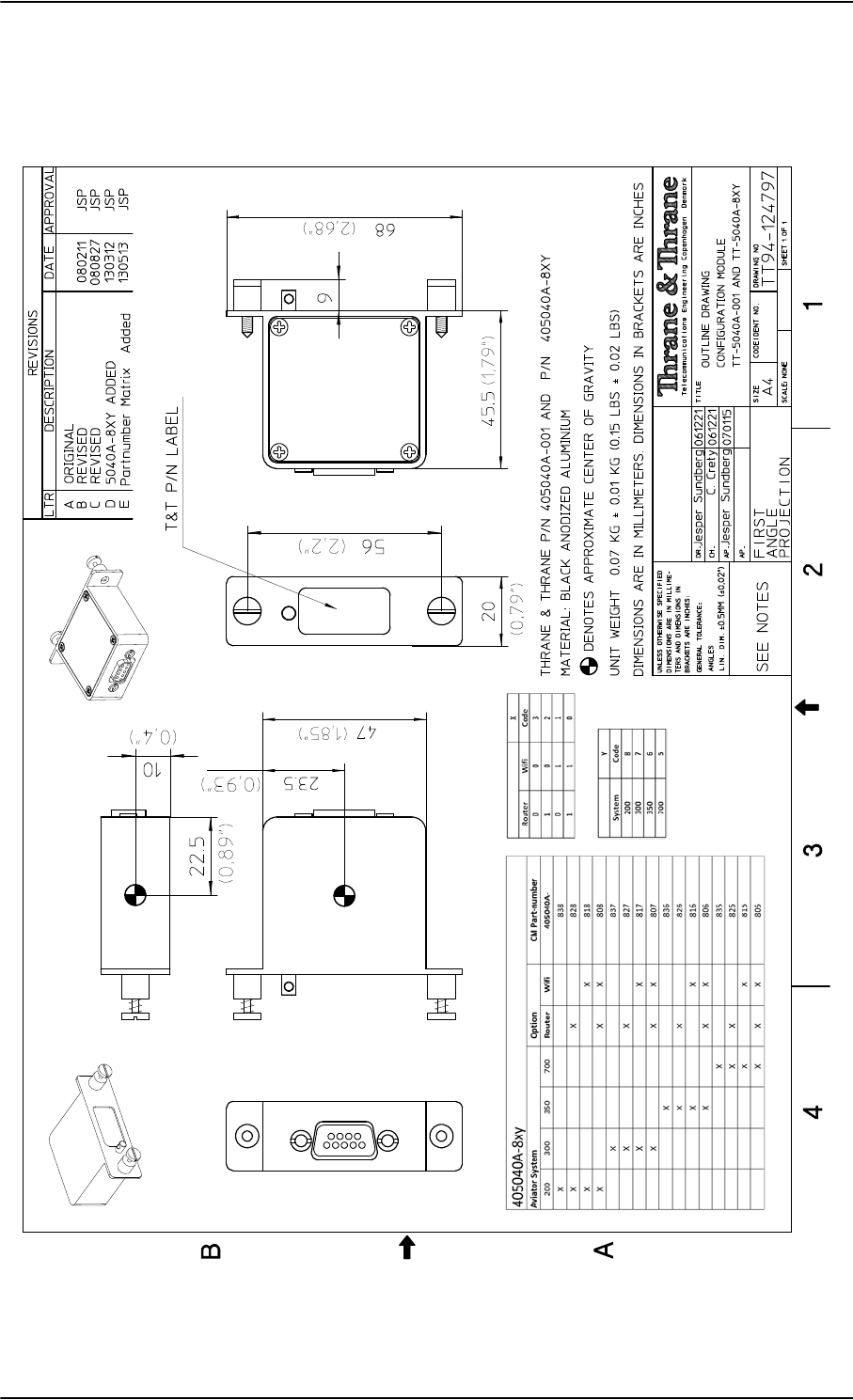
TT-5040A SBU
3-6 Chapter 3: Equipment drawings 98-124743-F
3.4.1 TT-5040A-001 CM (inserted in the SBU)
Figure 3-5: Outline drawing: TT-5040A-001 CM, inserted in the SBU
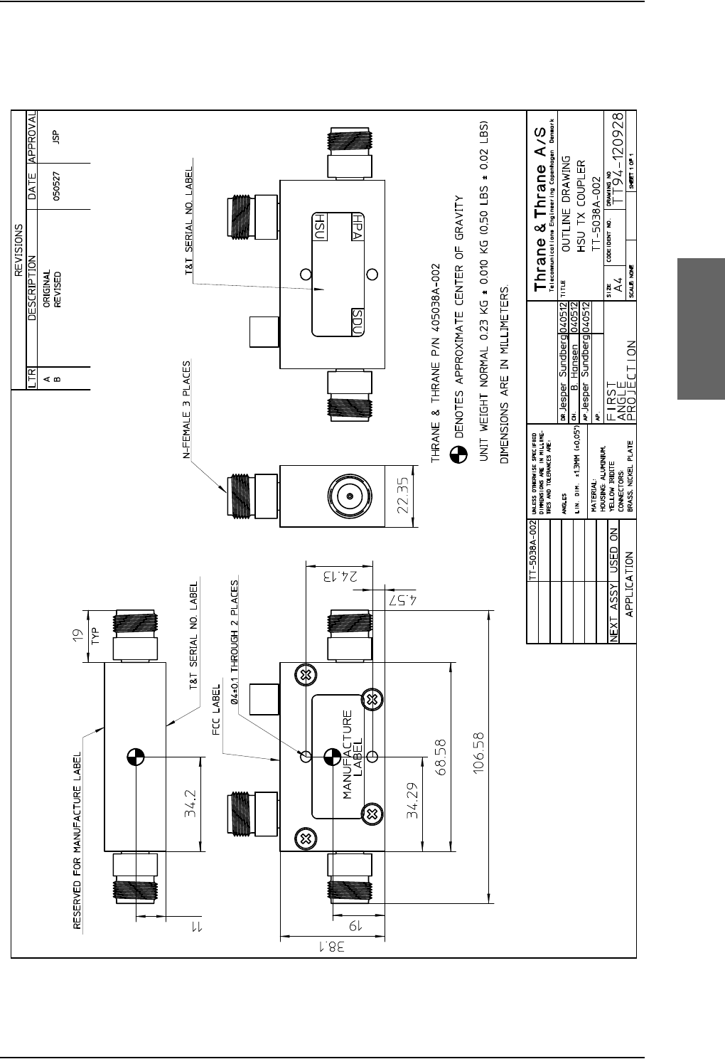
TT-5038A-002 Tx Coupler
98-124743-F Chapter 3: Equipment drawings 3-7
3.5 TT-5038A-002 Tx Coupler
Figure 3-6: Outline Drawing: Tx Coupler
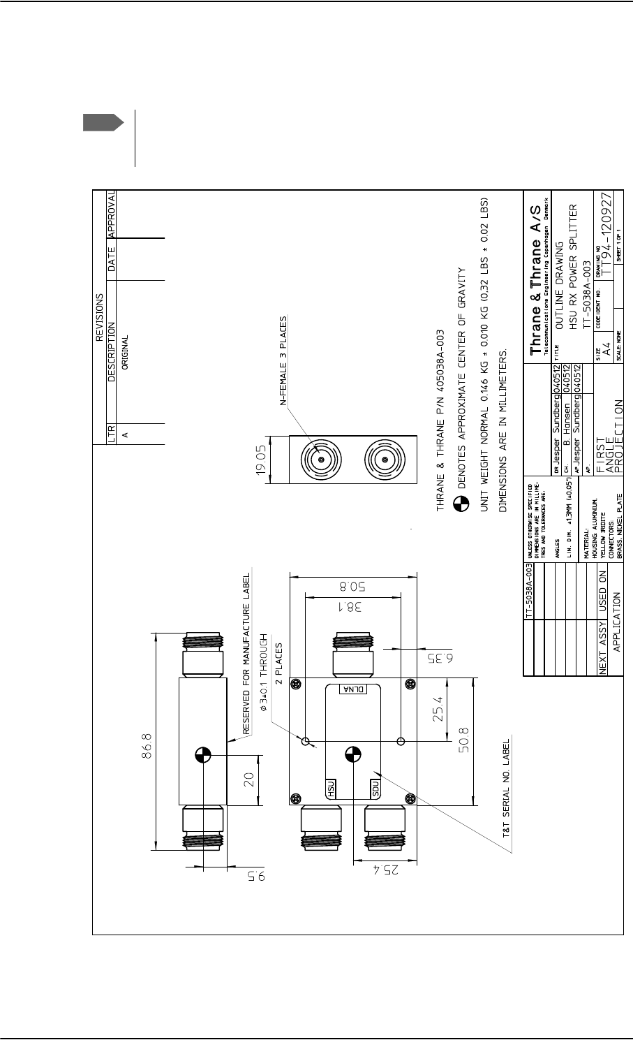
TT-5038A-003 Rx Power Splitter
3-8 Chapter 3: Equipment drawings 98-124743-F
3.6 TT-5038A-003 Rx Power Splitter
Note
If the Rx Power Splitter is to be mounted on a flat surface, mount it on a 3 mm
mounting plate to provide enough space for mounting of the connectors. For
further information see Rx Power Splitter on page 5-5.
Figure 3-7: Outline Drawing: Rx Power Splitter
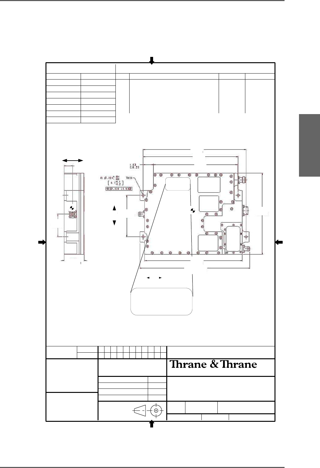
TT-5013A DLNA Type F
98-124743-F Chapter 3: Equipment drawings 3-9
3.7 TT-5013A DLNA Type F
Original Manufacturer P/N: COMDEV 173628-101
Figure 3-8: Outline drawing: DLNA Type F
111
405013A DLNA Type-F
Outline drawing
SHEET NO.
MATERIAL
A
REV STATUS
OF SHEETS
REV LTR
USED ON NEXT ASSY
405013A
DESCRIPTION
REVISIONS
LTR DATE APPROVAL
A ORIGINAL 28-01-2010 HN
B mm [ inches ] indication swoped 01-12-2010 HN
C 405013A OEM from comdev 14-08-2015 JCJ
APPLICATION
SHEET 1 OF 1
DRAWING NO.
TT94-130854
CODE IDENT NO.
94-130854-C.VSD
SIZE
A4
FIRST
ANGLE
PROJECTION
DR. Hans Norring 28-01-10 TITLE
Telecommunications Engineering Copenhagen Denmark
SCALE 2:1
CH. BMA 28-01-10
AP. BMA 28-01-10
AP. PT 21-09-11
A
/
S
UNLESS OTHERWISE SPECIFIED
DIMENSIONS ARE IN MILLIME-
TRES AND TOLERANCES ARE IN
ACCORDANCE WITH DS 22768.
ANGLES
LIN.DIM.
405013A
Placement of
Thrane (Cobham) S/N Label
A
B
C
D
E
G
J
K
H
F
A=10.350 [262.90]
B= 9.550 [242.57]
C= 8.464 [215.00]
D= 7.764 [197.20]
E= 9.852 [250.24]
F=11.099±0.04 [281.51]±0.013
G= 3.960 [100.50]
H= 2.000 [50.79] MAX
J= 2.180 [55.30]
K= 0.860 [21.90]
Dimentions are in inches/[mm]
Tolerances: ± 0.020/[0.5]
Unless otherwise stated.
CG [y,x,z]= 2,4[60.9], 5.09[129.3],0.70 [17.8].
0
Finish: mil-prf-85285 type 1, polyurethane #37038, cannoflage black
Surface roughness [1.6 micron] 63 microinch
Z
axis
Y axis
X axis
The 405013A DLNA is identical to the COMDEV 173628-101 Type-F
DLNA and the COMDEV 173628-101 MOD 01 Type-F DLNA.
B C
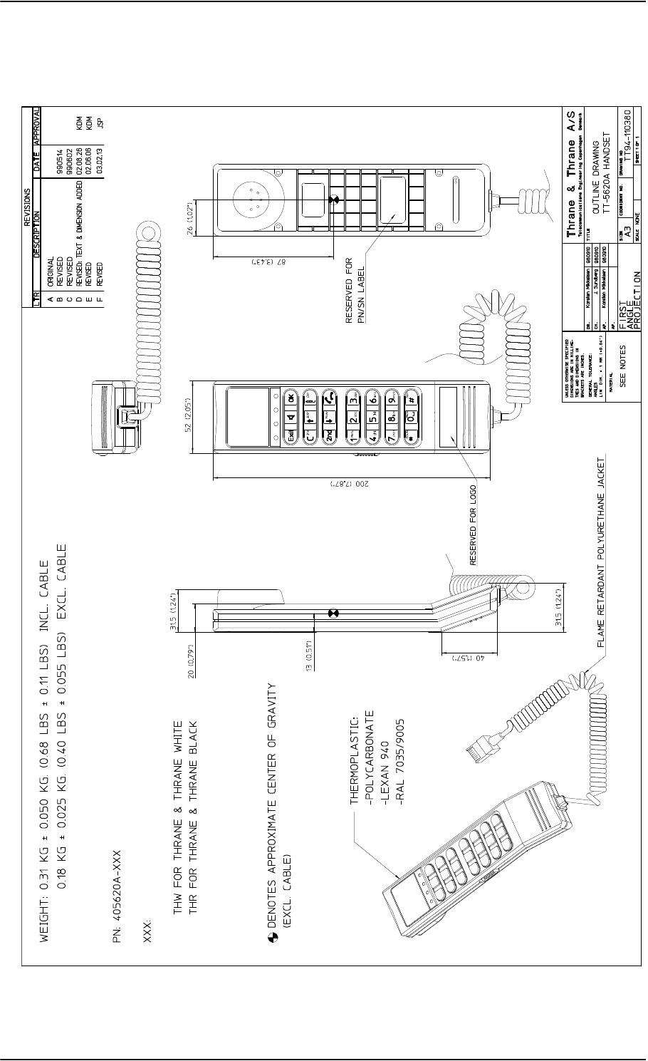
TT-5620A 4-Wire Handset
3-10 Chapter 3: Equipment drawings 98-124743-F
3.8 TT-5620A 4-Wire Handset
Figure 3-9: Outline Drawing: 4-Wire Handset
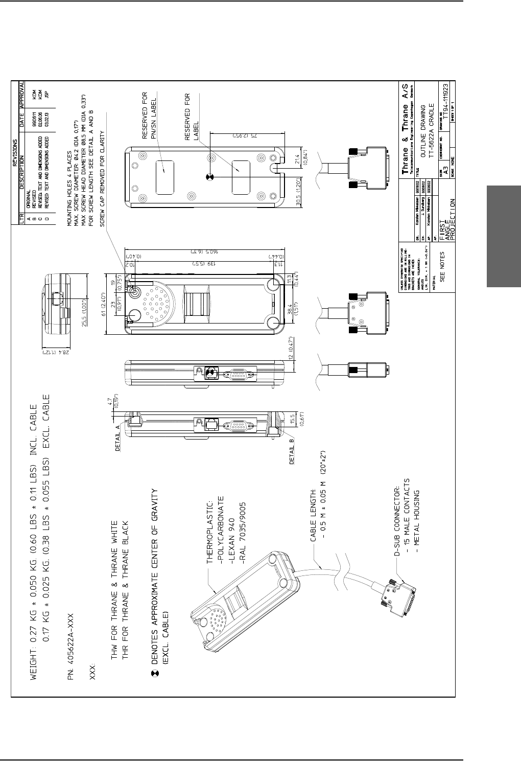
TT-5622A 4-Wire Cradle
98-124743-F Chapter 3: Equipment drawings 3-11
3.9 TT-5622A 4-Wire Cradle
Figure 3-10: Outline Drawing: 4-Wire Cradle
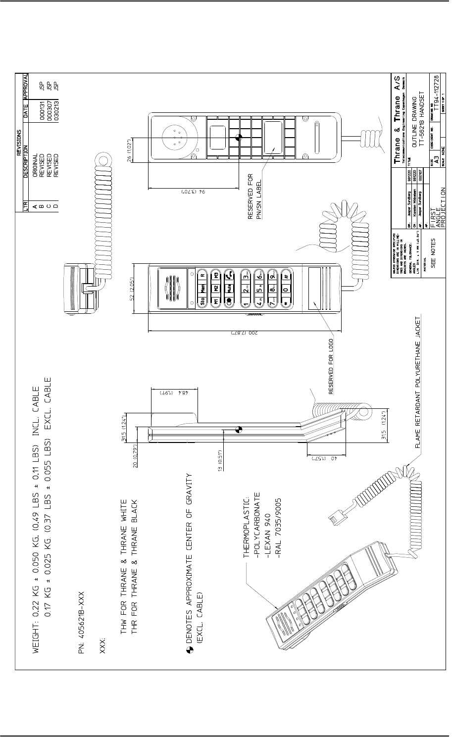
TT-5621B 2-Wire Handset
3-12 Chapter 3: Equipment drawings 98-124743-F
3.10 TT-5621B 2-Wire Handset
Figure 3-11: Outline drawing: TT-5621B 2-Wire Handset
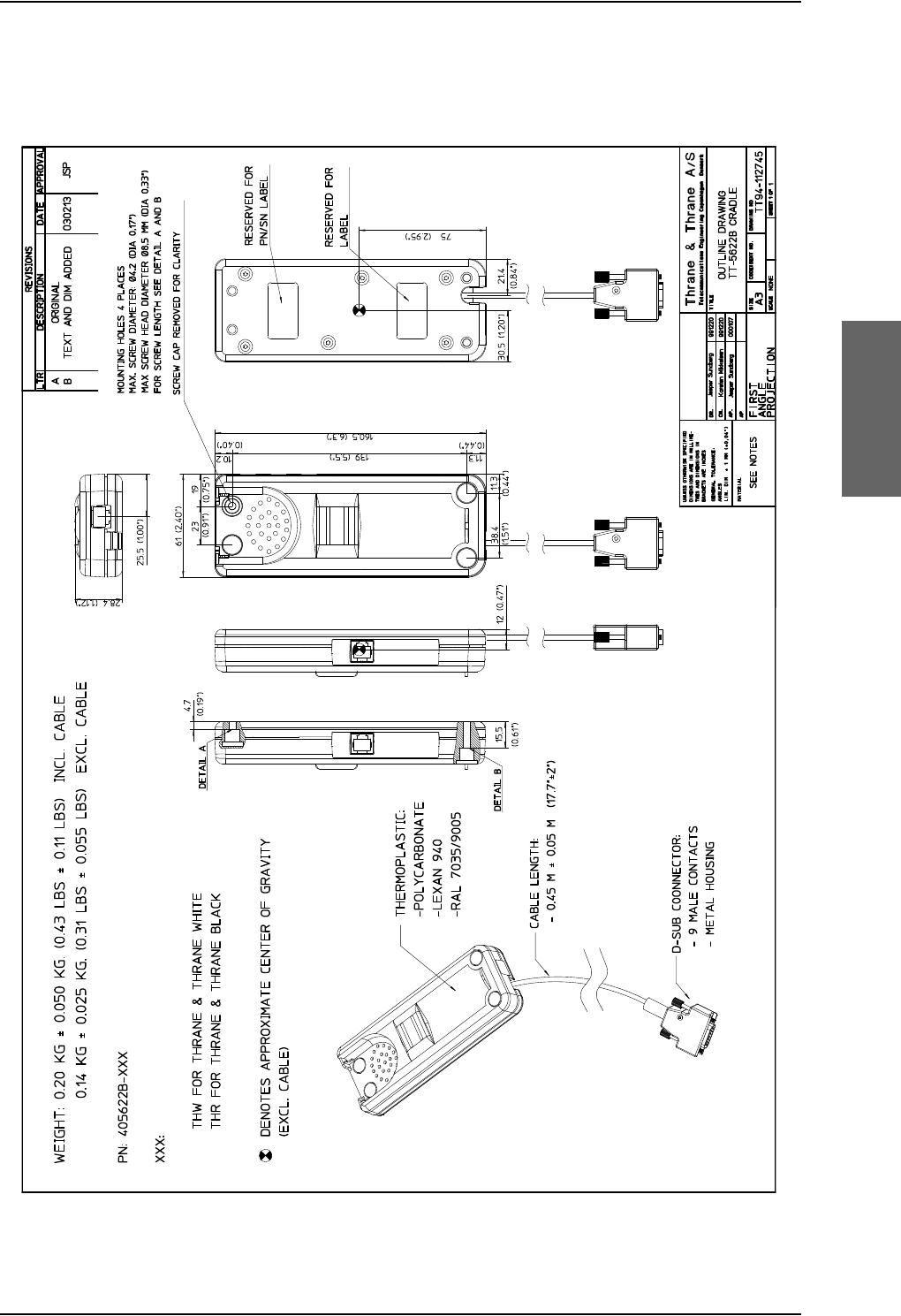
TT-5622B 2-Wire Cradle
98-124743-F Chapter 3: Equipment drawings 3-13
3.11 TT-5622B 2-Wire Cradle
Figure 3-12: Outline drawing: TT-5622B 2-Wire Cradle
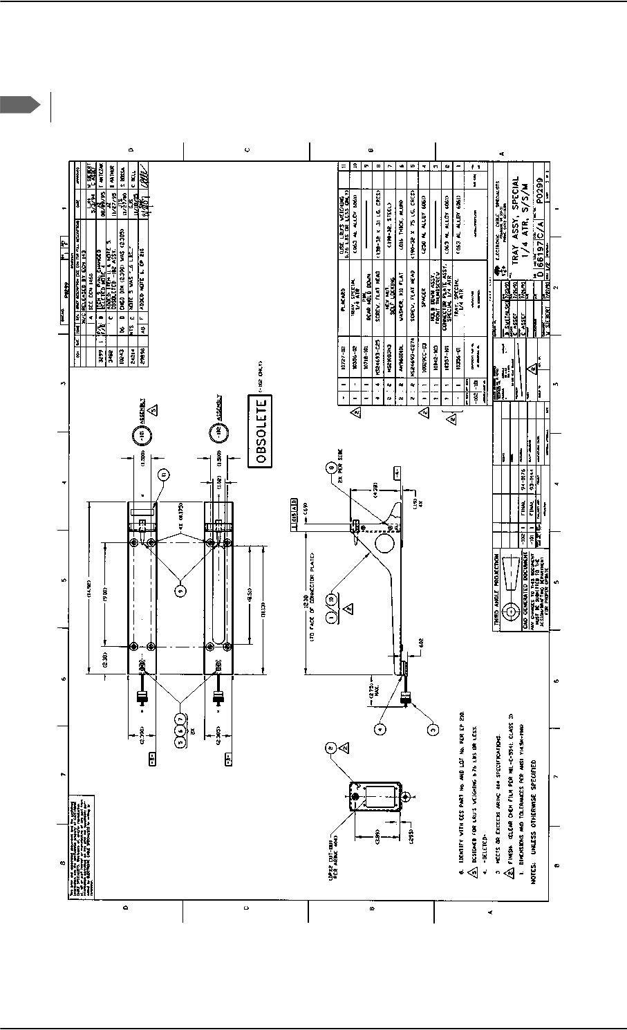
SBU trays
3-14 Chapter 3: Equipment drawings 98-124743-F
3.12 SBU trays
The comment OBSOLETE refers to the -102 assembly.
Figure 3-13: Outline drawing: SBU tray: ECS PO299-101
Note
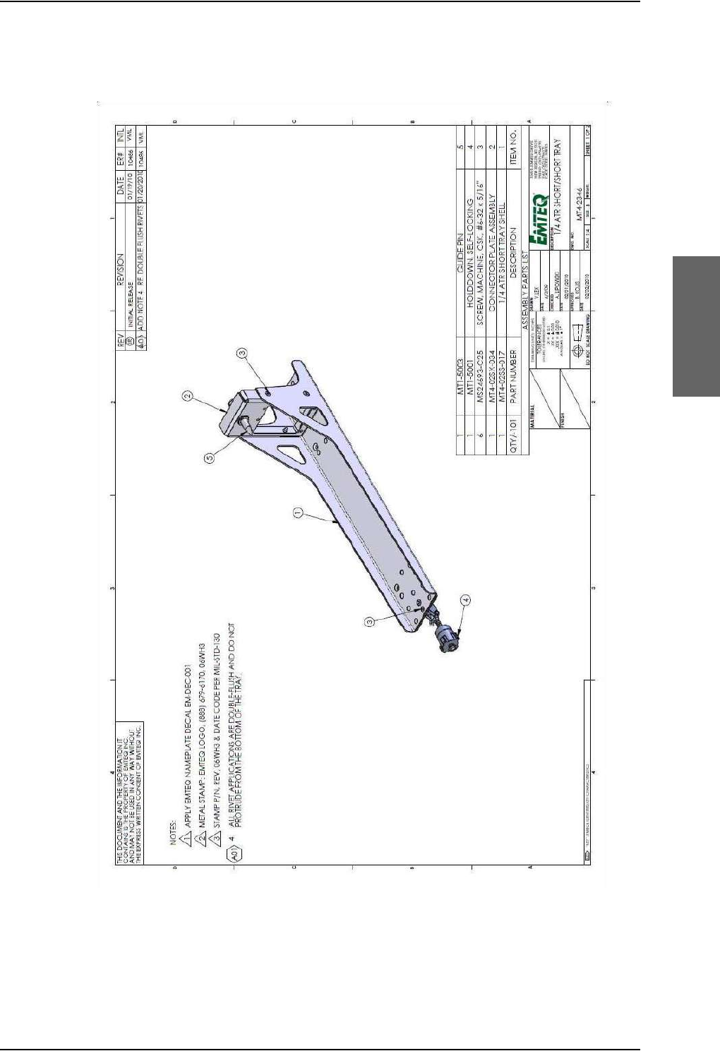
Figure 3-14: Outline drawing: SBU tray: EMTEQ MT4-2346-101 (page 1)
SBU trays
98-124743-F Chapter 3: Equipment drawings 3-15
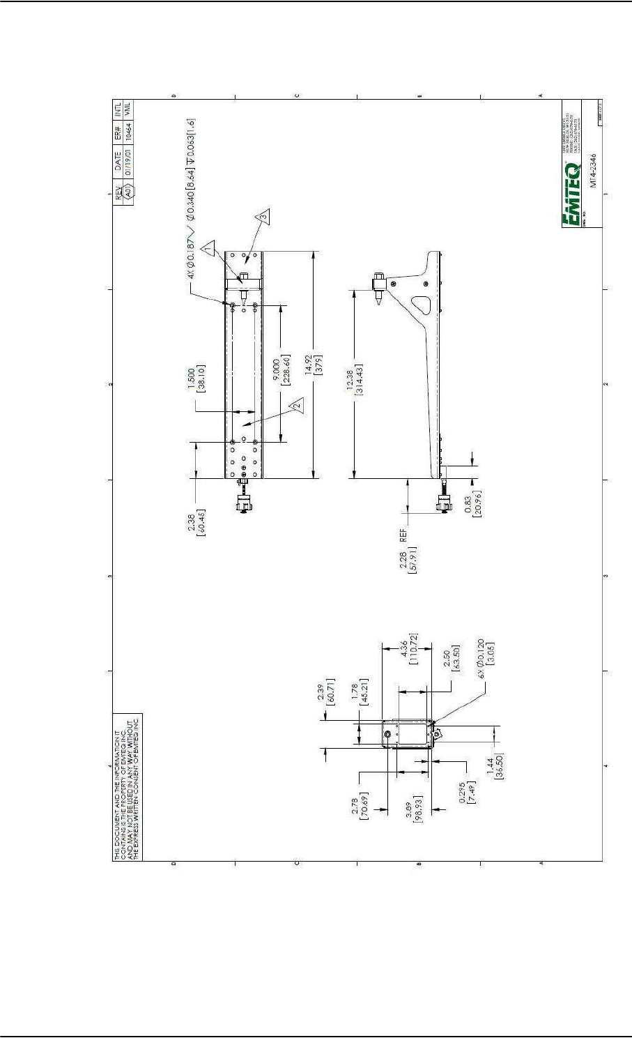
Figure 3-15: Outline drawing: SBU tray: EMTEQ MT4-2346-101 (page 2)
SBU trays
3-16 Chapter 3: Equipment drawings 98-124743-F
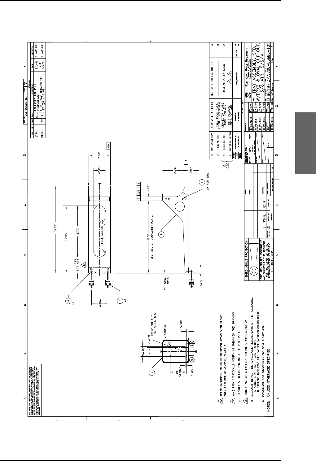
SBU trays
98-124743-F Chapter 3: Equipment drawings 3-17
3.12.1 SDU and HPA tray
Figure 3-16: Outline Drawing: Tray for SDU and HPA.
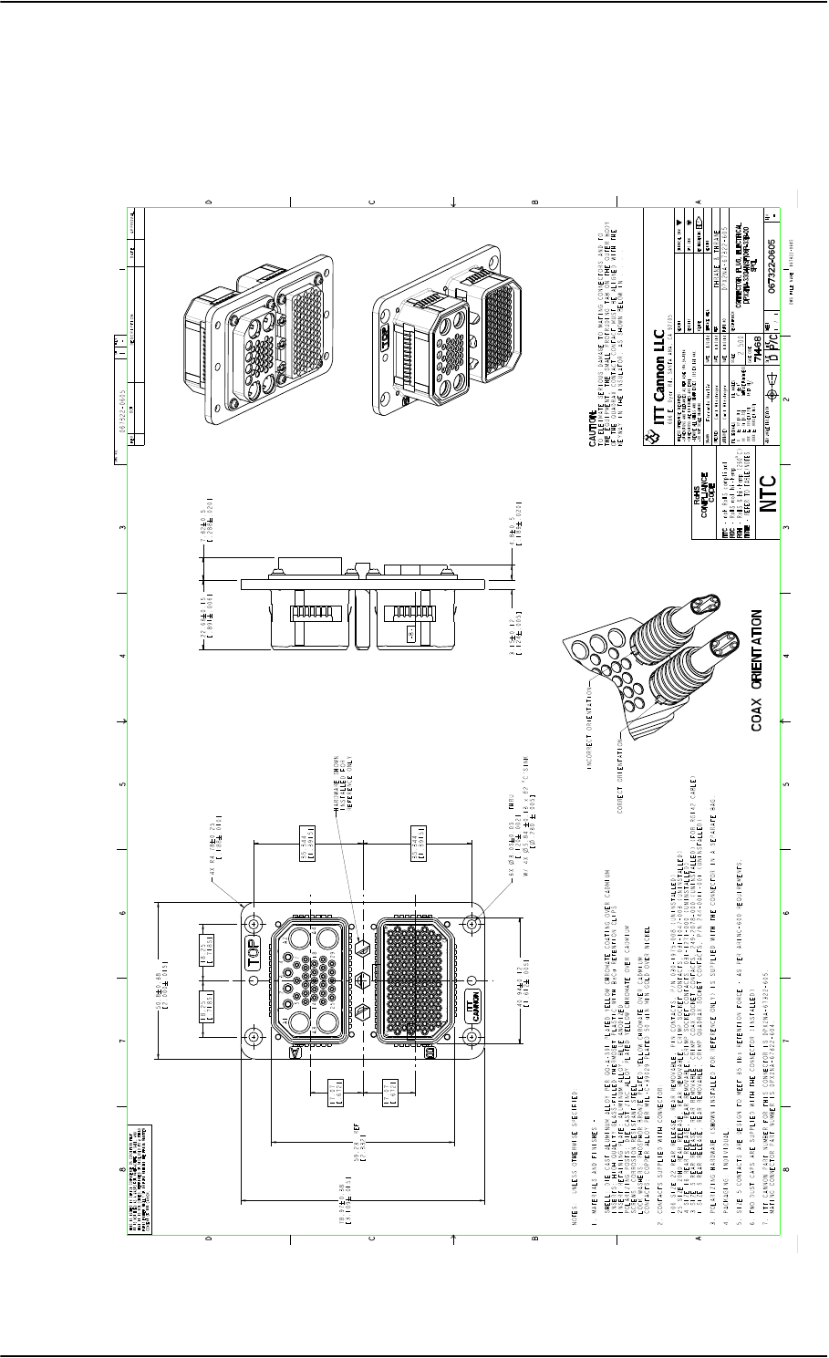
SDU tray connector
3-18 Chapter 3: Equipment drawings 98-124743-F
3.13 SDU tray connector
For correct index pin codes for the SDU see Figure 4-2: SDU Rear Receptacle and
Mating Plug in Tray, Engaging End.
Figure 3-17: SDU Tray Connector: ITT Canon DPX2NA-67322-605
Export Administration Regulations (15 CFR 730, et seq.). Any transfer of this data to non-US persons or to any location outside the United States must be in compliance with the Export Administration Regulations.
This document contains technical data that is subject to export controls under the Export Administration Act and
EXPORT CODE C
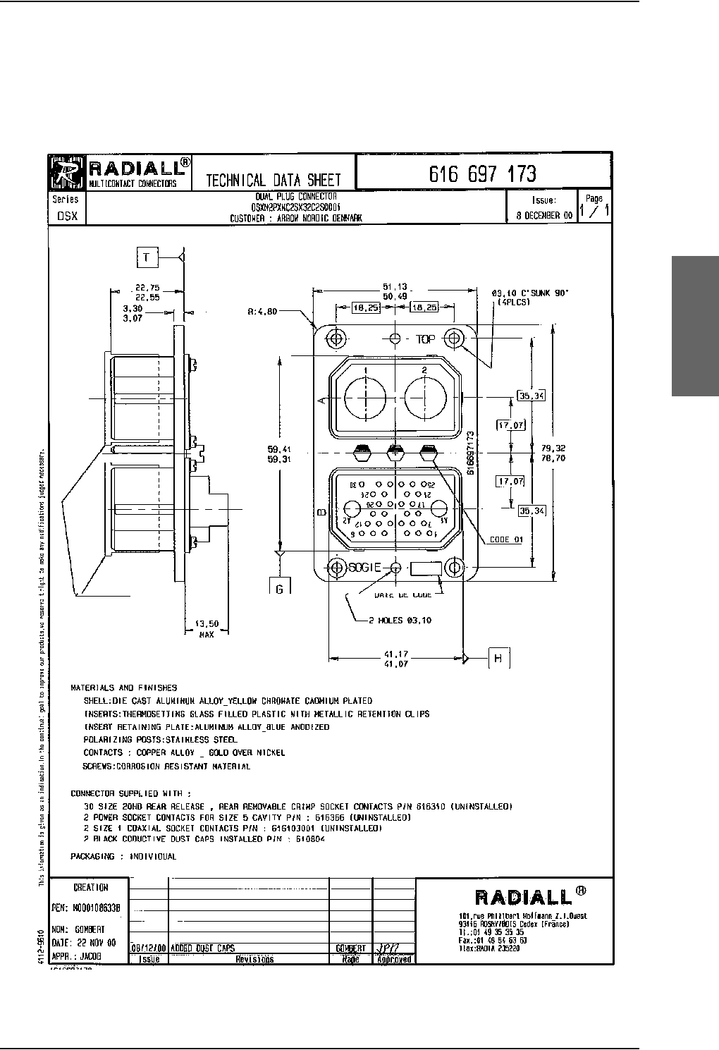
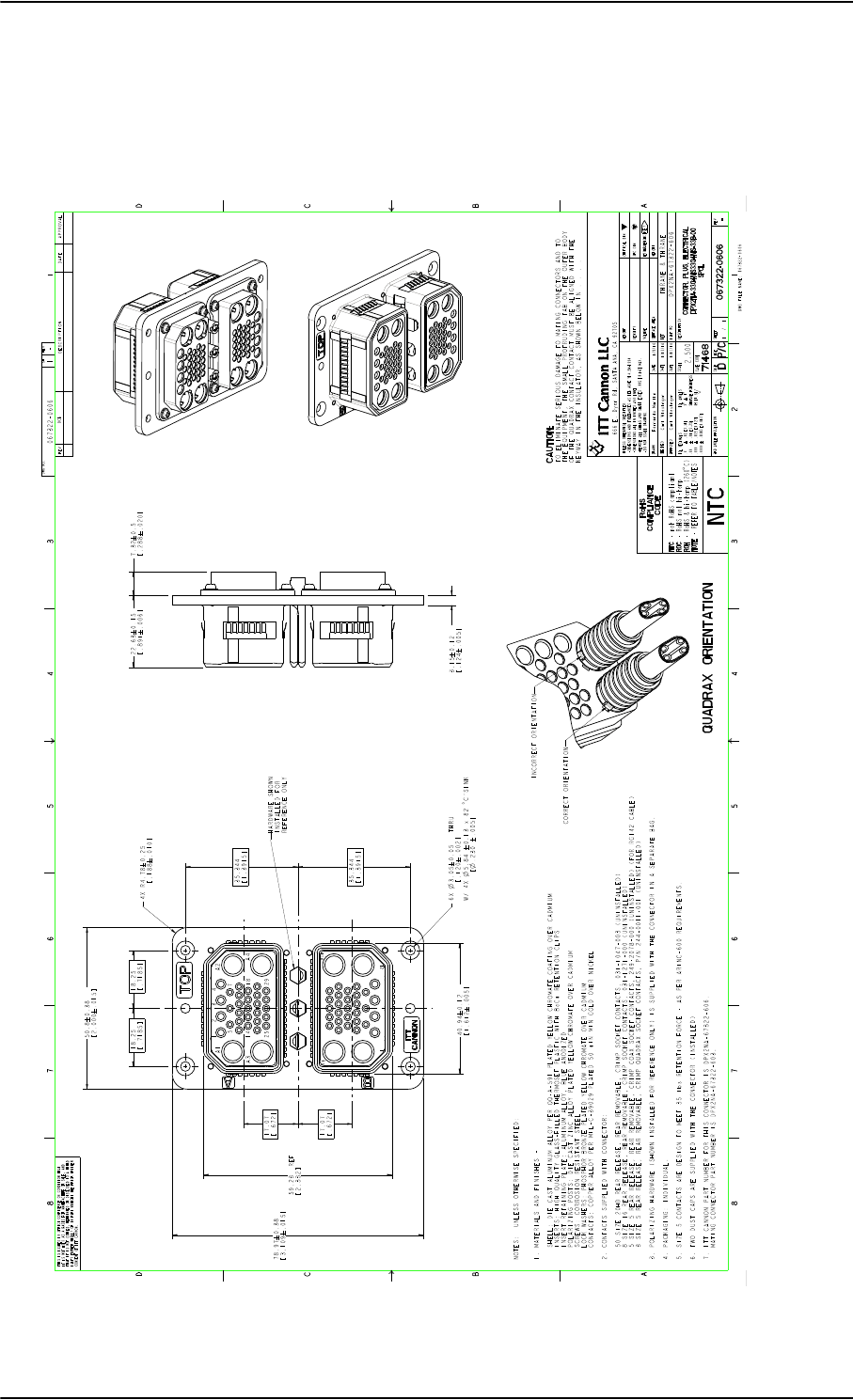
SBU tray connector
3-20 Chapter 3: Equipment drawings 98-124743-F
3.15 SBU tray connector
For correct index pin codes for the SBU see Figure 4-5: SBU rear receptacle, engaging
end (Index code: 19).
Figure 3-19: Outline drawing: SBU tray connector: ITT Cannon DPX2NA-67322-606
Export Administration Regulations (15 CFR 730, et seq.). Any transfer of this data to non-US persons or to any location outside the United States must be in compliance with the Export Administration Regulations.
This document contains technical data that is subject to export controls under the Export Administration Act and
EXPORT CODE C
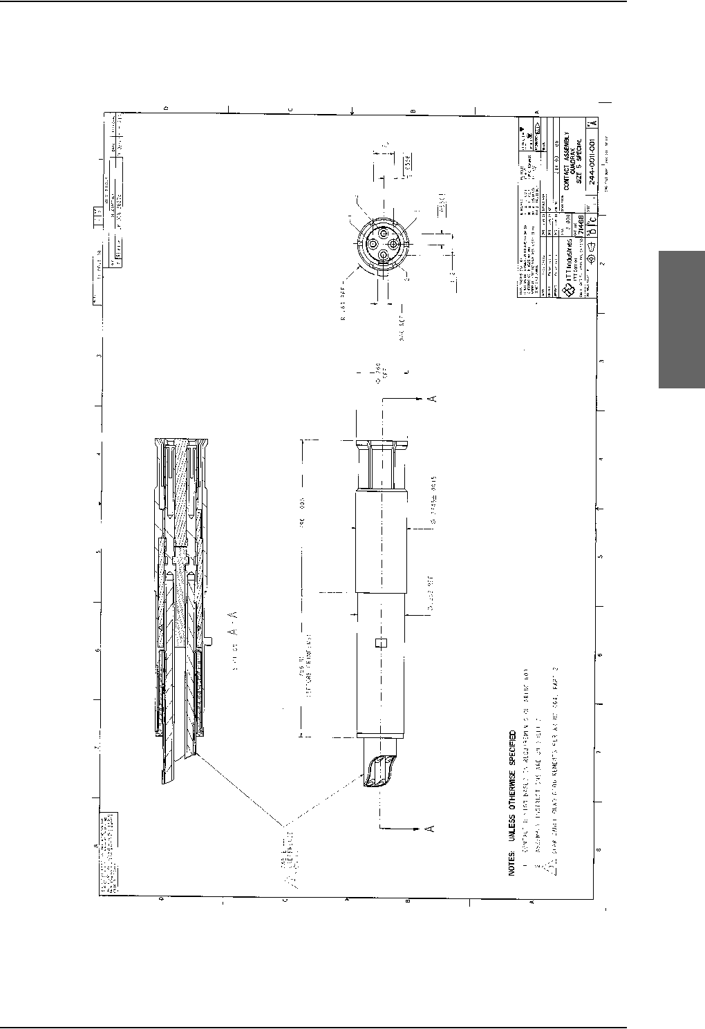
Contact Assembly: Quadrax Pin size 5 special
98-124743-F Chapter 3: Equipment drawings 3-21
3.16 Contact Assembly: Quadrax Pin size 5 special
Figure 3-20: Contact Assembly: Quadrax Pin size 5 special: ITT Cannon 244-0011-001
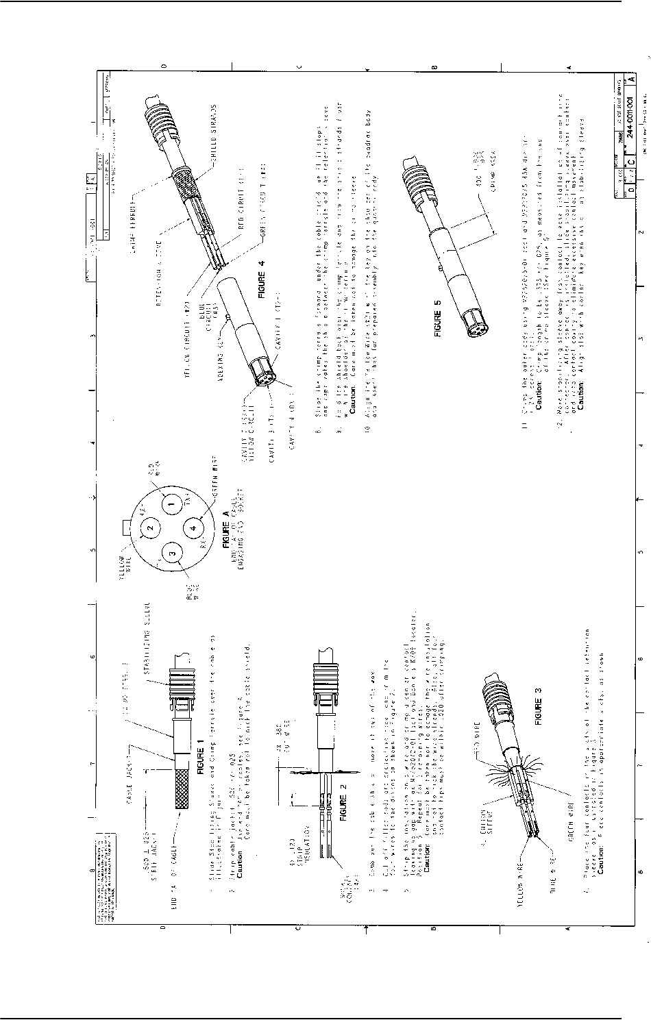
Contact Assembly: Quadrax Pin size 5 special
3-22 Chapter 3: Equipment drawings 98-124743-F
Figure 3-20: Contact Assembly: Quadrax Pin size 5 special: ITT Cannon 244-0011-001 (Continued)
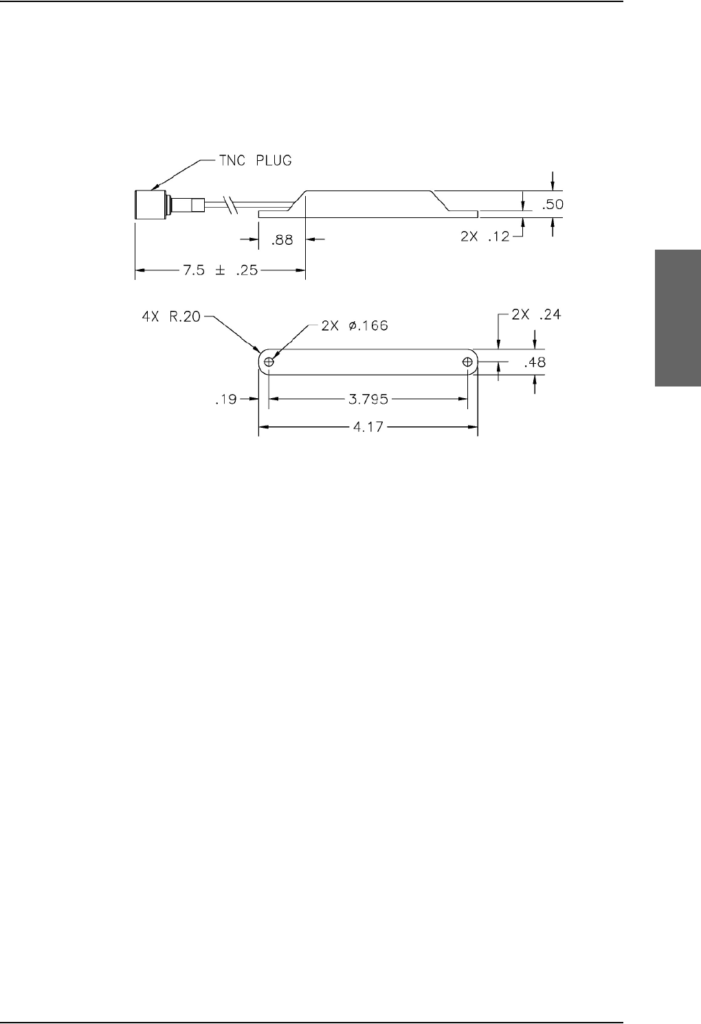
TT-5040A-004 WLAN antenna
98-124743-F Chapter 3: Equipment drawings 3-23
3.17 TT-5040A-004 WLAN antenna
Original Manufacturer P/N: VT Miltope 901167-2.
Figure 3-21: Outline drawing: TT-5040A-004 WLAN antenna
Measures are in inches.

TT-5040A-004 WLAN antenna
3-24 Chapter 3: Equipment drawings 98-124743-F

98-124743-F 4-1
Chapter 4
Connectors and pin-out 4
4.1 TT-5035A Satellite Data Unit
4.1.1 Connectors on SDU
There are three connectors on the SDU:
• Maintenance (front connector):
Interface to PC and Handset for configuration and maintenance purposes.
A 15 pin Female Sub-D Filter connector
•ARINC 404 (rear connector):
Interfaces to Aircraft and SATCOM interconnections.
An ARINC 404 Shell Size 2 Receptacle.
• Configuration Module (rear, inside connector):
A 9 pin Sub-D Female Connector. This is an internal connector used only as interface to
the Configuration Module.

TT-5035A Satellite Data Unit
4-2 Chapter 4: Connectors and pin-out 98-124743-F
4.1.2 SDU Maintenance front connector
Connector drawing
Functions
The front connector is a 15 pin Female Sub-D Filter connector, and contains the following
interfaces:
• EIA/TIA-232-E PC port to connect to PC with Aero-SDU Configuration Program
• 4-Wire Thrane & Thrane Handset
• RS-485 Data interface for T&T Handset
•+12 V DC for powering the Handset
• Write Enable Input for Configuration Module.
Figure 4-1: SDU Front Connector, Face
View of Engaging End. (DB15F)

TT-5035A Satellite Data Unit
98-124743-F Chapter 4: Connectors and pin-out 4-3
Pin-out for SDU front connector
Pin. No. Pin Name
FP1 Maintenance Handset Audio In Hi
FP2 Maintenance Handset Audio In Lo
FP3 Maintenance Handset Audio Out Hi
FP4 Maintenance Handset Audio Out Lo
FP5 Signal Ground SGND
FP6 Maintenance Handset RS-485 Data A
FP7 Maintenance Handset RS-485 Data B
FP8 +12 V DC/120 mA
FP9 GND, Power Return (for +12 V DC)
FP10 PC EIA/TIA-232-E RxD Output
FP11 PC EIA/TIA-232-E TxD Input
FP12 PC EIA/TIA-232-E CTS Output
FP13 PC EIA/TIA-232-E RTS Input
FP14 GND
FP15 Configuration Module Write Enable In
Table 4-1: Pin-out for SDU Front Connector
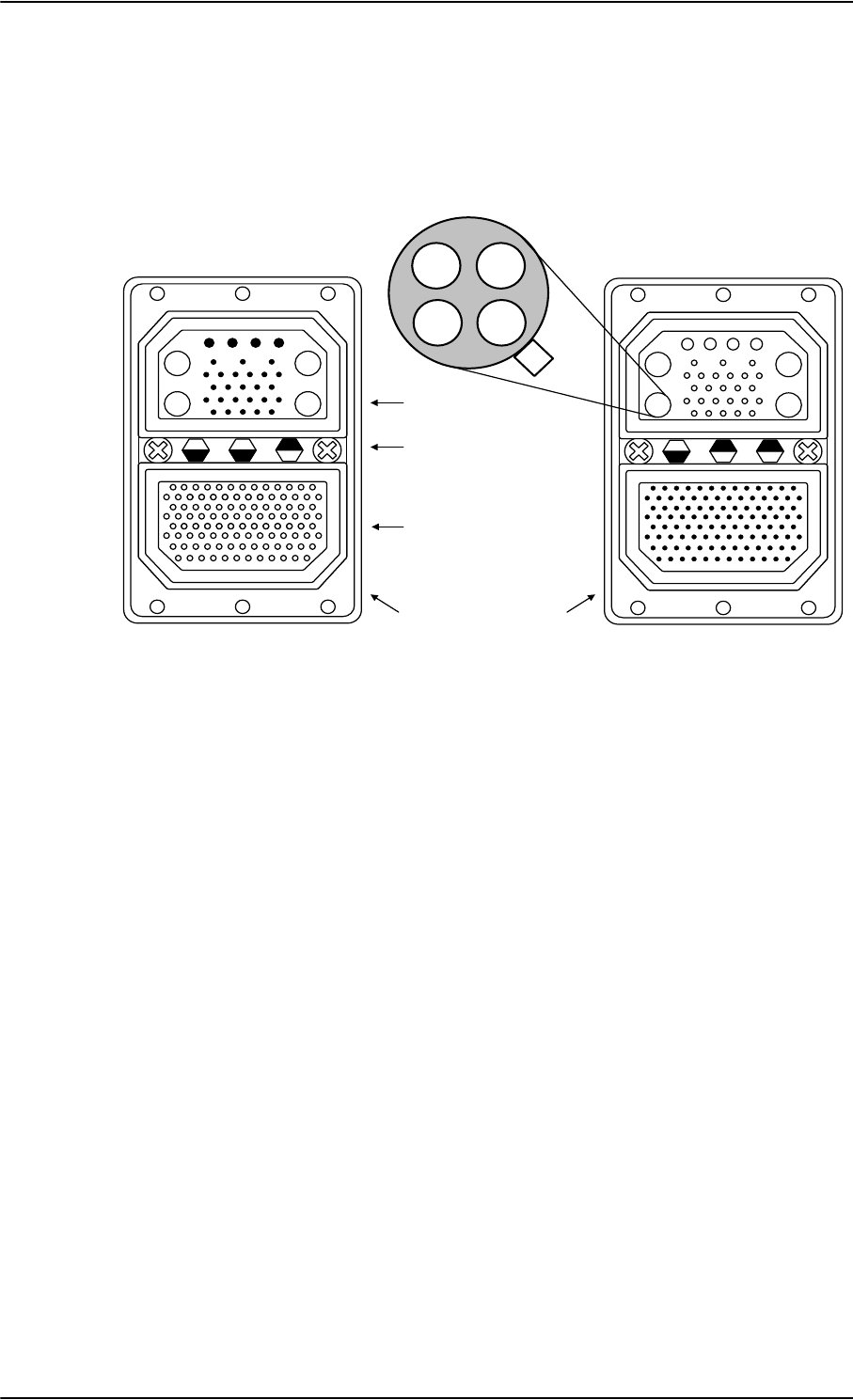
TT-5035A Satellite Data Unit
4-4 Chapter 4: Connectors and pin-out 98-124743-F
4.1.3 SDU rear receptacle
Connector drawing
Functions, top plug
The Top Plug (TP) connects the following signals:
Power, RF Interfaces and Antenna Modem:
•+28 V DC Power + chassis ground
•+28 V DC/600 mA 4-wire handset supply
• Remote ON/OFF (nON)
• RF Tx signal to HPA
•RF Rx signal from DLNA
• GPS/Antenna modem interface
Handset interfaces (analog):
• Four analog 4-wire interfaces for Thrane & Thrane Handsets Systems (including
+28 V DC handset supply with nON/OFF power supply control)
Voice/Fax/Modem interfaces:
• Two Voice/Fax/Modem/STU-III, analog 2-wire standard POTS interfaces
Figure 4-2: SDU Rear Receptacle and Mating Plug in Tray, Engaging End
$$
$$
7RS3OXJ73,QVHUW
%RWWRP3OXJ%3,QVHUW
,QGH[3LQ&RGH
/LJKWDUHDVDUHNH\KROHV
9LHZ(QJDJLQJ(QG
4XDGUD[(WKHUQHW,QVHUW
LQ$
$ $
$ $
6'85HDU5HFHSWDFOH 0DWLQJ3OXJLQ7UD\

TT-5035A Satellite Data Unit
98-124743-F Chapter 4: Connectors and pin-out 4-5
Functions, bottom plug
The Bottom Plug (BP) connects the following signals:
Aircraft Avionics Interfaces:
• 24 bit discrete hardwire strapped ICAO address
•Two high speed ARINC 429 Inertial Reference System (IRS) or
•Two high or low speed ARINC 429 Attitude and Heading Reference System (AHRS)
•Two high or low ARINC 429 Communication Management Units (ACARS/AFIS/CMU)
• Three high or low speed ARINC 429 MCDU (1 output, 2 inputs)
• Two Discrete inputs for “Weight On Wheels”
• Discrete Inputs/Outputs for WH-10/MagnaStar AIU control or Cockpit Voice
SATCOM Interfaces:
• One RS-422 SBU control interface
• One RS-422 Multi Control HPA Interface (Tx)
• One RS-422 BITE/Status HPA Interface (Rx)
• One Discrete HPA Remote nON/OFF output
Maintenance Interfaces:
• One Discrete SDU Hardware Reset
Handset interfaces (digital):
• Four RS-485 data interfaces for Thrane & Thrane Handsets
Other interfaces:
• Three Annunciators: #1 “Call”, #2 “Fax” and #3 “Service Available”
• Three ATE pins (Automatic Test Equipment) - Do not connect!

TT-5035A Satellite Data Unit
4-6 Chapter 4: Connectors and pin-out 98-124743-F
Pin-out for SDU rear receptacle (top plug)
Table 4-2: Pin-out for SDU Rear Receptacle (Top Plug)
Pin No. Pin Name
TP A1 RF Rx input from power splitter
TP A2 RF Tx output to coupler (Coax)
TP
A3.1
Tx + 10BaseT Ethernet (Swift64
MPDS)
TP
A3.2
Rx + 10BaseT Ethernet (Swift64
MPDS)
TP
A3.3
Tx - 10BaseT Ethernet (Swift64
MPDS)
TP
A3.4
Rx - 10BaseT Ethernet (Swift64 MPDS)
TP A4 GPS/Antenna Modem Interface (Coax)
TP1 +28 V DC Power
TP2 GND, Power Return
TP3 Chassis Ground and Handset Power
Return
TP4 +28 V DC/600 mA Handset Supply
TP5 Remote ON/OFF (nON)
TP6 2-Wire Voice/Fax/Modem #5 (Ring)
TP7 2-Wire Voice/Fax/Modem #6 (Ring)
TP8 2-Wire Voice/Fax/Modem #6 (Tip)
TP9 Not Connected
TP10 Handset #1 Audio In Hi /
Cockpit Voice Audio #1 In Hi
TP11 Handset #1 Audio In Lo /
Cockpit Voice Audio #1 In Lo
TP12 Handset #1 Audio Out Hi /
Cockpit Voice Audio #1 Out Hi
TP13 Handset #1 Audio Out Lo /
Cockpit Voice Audio #1 Out Lo
TP14 Not Connected
TP15 Handset #2 Audio In Hi /
Cockpit Voice Audio #2 In Hi
TP16 Handset #2 Audio In Lo /
Cockpit Voice Audio #2 In Lo
TP17 Handset #2 Audio Out Hi /
Cockpit Voice Audio #2 Out Hi
TP18 Handset #2 Audio Out Lo /
Cockpit Voice Audio #2 Out Lo
TP19 2-Wire Voice/Fax/Modem #5 (Tip)
TP20 AGND
TP21 Handset #3 Audio In Hi
TP22 Handset #3 audio In Lo
TP23 Handset #3 audio Out Hi
TP24 Handset #3 audio Out Lo
TP25 Do not connect!
(+12 V DC / 25 mA)
TP26 Handset #4 audio In Hi
TP27 Handset #4 audio In Lo
TP28 Handset #4 audio Out Hi
TP29 Handset #4 audio Out Lo
Pin No. Pin Name

TT-5035A Satellite Data Unit
98-124743-F Chapter 4: Connectors and pin-out 4-7
Pin-out for SDU rear receptacle (bottom plug)
Pin No. Pin Name
BP1 ICAO Address Bit #1 (MSB)
BP2 ICAO Address Bit #2
BP3 ICAO Address Bit #3
BP4 ICAO Address Bit #4
BP5 ICAO Address Bit #5
BP6 ICAO Address Bit #6
BP7 ICAO Address Bit #7
BP8 ICAO Address Bit #8
BP9 ICAO Address Bit #9
BP10 ICAO Address Bit #10
BP11 ICAO Address Bit #11
BP12 ICAO Address Bit #12
BP13 ICAO Address Bit #13
BP14 ICAO Address Bit #14
BP15 ICAO Address Bit #15
BP16 ICAO Address Bit #16
BP17 ICAO Address Bit #17
BP18 ICAO Address Bit #18
BP19 ICAO Address Bit #19
BP20 ICAO Address Bit #20
BP21 ICAO Address Bit #21
BP22 ICAO Address Bit #22
BP23 ICAO Address Bit #23
BP24 ICAO Address Bit #24
BP25 ICAO Address Common
BP26 Data from primary IRS 429 A / Data
from primary AHRS 429 A
BP27 Data from primary IRS 429 B / Data
from primary AHRS 429 B
BP28 Data from second IRS 429 A / Data
from second AHRS 429 A
BP29 Data from second IRS 429 B / Data
from second AHRS 429 B
BP30 Data bus from MCDU #2 input 429 A
BP31 Data bus from MCDU #2 input 429 B
BP32 Spare #1 429 A
BP33 Spare #1 429 B
BP34 Spare #1 429 A
BP35 Spare #1 429 B
BP36 Spare #2 429 A
BP37 Spare #2 429 B
BP38 Spare #2 429 A
BP39 Spare #2 429 B
BP40 Data bus from ACARS / AFIS / CMU #1
429 A
BP41 Data bus from ACARS / AFIS / CMU #1
429 B
BP42 Data bus to ACARS / AFIS /
CMU #1 & #2 429 A
BP43 Data bus to ACARS / AFIS /
CMU #1 & #2 429 B
BP44 Data bus from ACARS / AFIS / CMU #2
429 A
BP45 Data bus from ACARS / AFIS /
CMU #2 429 B
Pin No. Pin Name

TT-5035A Satellite Data Unit
4-8 Chapter 4: Connectors and pin-out 98-124743-F
Pin No. Pin Name
BP46 Data bus from MCDU #1 429 A
BP47 Data bus from MCDU #1 429 B
BP48 Data bus to MCDU #1 & #2 429 A
BP49 Data bus to MCDU #1 & #2 429 B
BP50 Reserved for Weight-On-Wheels Input
#1
BP51 Reserved for Weight-On-Wheels Input
#2
BP52 CP Voice Chime Signal Contact #1;
Current from Chime
BP53 CP Voice Chime Signal Contact #2;
Current to Chime
BP54 MagnaStar/ICS-200: Satcom Service
Unavailable
BP55 WH-10/MagnaStar Hook switch #3 or
ICS-200 Ringer Input #3
BP56 SBU Enable output
BP57 HPA remote nON/OFF output
BP58 Spare TxD-B RS-422 (I)
BP59 Spare TxD-A RS-422 (I)
BP60 Spare RxD-B RS-422 (O)
BP61 Spare RxD-A RS-422 (O)
BP62 Spare RTS-B RS-422 (I)
BP63 Spare RTS-A RS-422 (I)
BP64 Spare CTS-B RS-422 (O)
BP65 Spare CTS-A RS-422 (O)
BP66 ISDN RxP (c)
BP67 ISDN TxP (d)
BP68 ISDN TxN (e)
BP69 ISDN RxN (f)
BP70 Data bus output to SBU;
Output B, RS-422
BP71 Data bus output to SBU;
Output A, RS-422
BP72 Data bus input from SBU;
Input B, RS-422
BP73 Data bus input from SBU;
Input A, RS-422
BP74 ATE 1 Do not connect!
BP75 ATE 2 Do not connect!
BP76 ATE 3 Do not connect!
BP77 SDU Reset, Active Low
BP78 HPA Control Output A, RS-422
BP79 HPA Control Output B, RS-422
BP80 HPA Data/BITE Input A, RS-422
BP81 HPA Data/BITE Input B, RS-422
BP82 WH-10/MagnaStar Hook Switch #1 or
ICS-200 Ringer Input #1 or
CP Voice Call Cancel Input #1 (Discrete
I)
BP83 WH-10/MagnaStar Ringer Output A1 or
ICS-200 Chan avail or
CP Voice Mic On Input #1 (Discrete
I/O)
BP84 WH-10/MagnaStar Ringer Output B1 or
ICS-200 Hook Switch Output #1 or
CP Voice Call Light Output #1 (Discrete
O)
BP85 WH-10/MagnaStar Hook Switch #2 or
ICS-200 Ringer Input #2 or
CP Voice Call Cancel Input #2 (Discrete
I)
BP86 WH-10/MagnaStar Ringer Output A2 or
ICS-200 Chan avail or
CP Voice Mic On Input #2 (Discrete
I/O)
Pin No. Pin Name

TT-5035A Satellite Data Unit
98-124743-F Chapter 4: Connectors and pin-out 4-9
Table 4-3: Pin-out for SDU Rear Receptacle (Bottom Plug)
Pin No. Pin Name
BP87 WH-10/MagnaStar Ringer Output B2 or
ICS-200 Hook Switch Output #2 or
CP Voice Call Light Output #2 (Discrete
O)
BP88 Chime/ Lamps Inhibit Input (Discrete I)
BP89 WH-10/MagnaStar Ringer Output A3 or
ICS-200 Chan avail or
Annunciator #3 (Discrete I/O)
BP90 WH-10/MagnaStar Ringer Output B3 or
ICS-200 Hook Switch Output #3
BP91 CP Voice Chime Reset Input #1
(Discrete I)
BP92 Annunciator #1 (Discrete I/O)
BP93 Annunciator #2 (Discrete Output)
BP94 4-Wire Handset #1
RS-485 Data A
BP95 4-Wire Handset #1
RS-485 Data B
BP96 4-Wire Handset #2
RS-485 Data A
BP97 4-Wire Handset #2
RS-485 Data B
BP98 4-Wire Handset #3
RS-485 Data A
BP99 4-Wire Handset #3
RS-485 Data B
BP100 4-Wire Handset #4
RS-485 Data A
BP101 4-Wire Handset #4
RS-485 Data B
BP102 Spare DTR-B RS-422 (I)
BP103 Spare DTR-A RS-422 (I)
BP104 Spare DCD-B RS-422 (O)
BP105 Spare DCD-A RS-422 (O)
BP106 Port 1 GND
Pin No. Pin Name
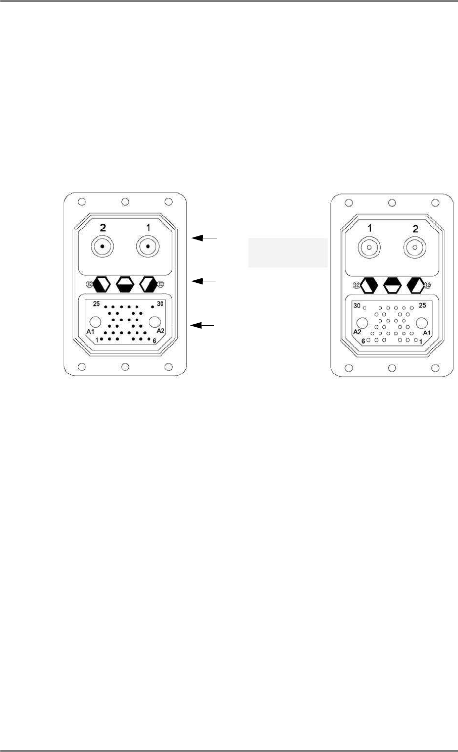
TT-5014A High Power Amplifier
4-10 Chapter 4: Connectors and pin-out 98-124743-F
4.2 TT-5014A High Power Amplifier
4.2.1 HPA rear receptacle
The HPA has one connector: An ARINC 404, shell size 2, rear receptacle, used for
connection to the antenna system and the SDU.
Connector drawing
Functions
The Top Plug connects the following signals:
• RF Tx signal to DLNA
• RF Tx signal from SDU
The Bottom Plug connects the following signals:
•+28 V DC Power (Aircraft Power Bus)
•Chassis ground
•ARINC 429 Tx and Rx connections for interfacing to ARINC 741 antennas
• Remote ON/OFF (nON) from SDU
• RS-422 data interface to SDU
Figure 4-3: HPA Receptacle, Face View of Engaging End. Index Code is 08
Index pin code 08
Light areas are key holes
Top plug (TP)
Bottom plug (BP)
HPA Rear Receptacle Mating Plug in Tray

TT-5014A High Power Amplifier
98-124743-F Chapter 4: Connectors and pin-out 4-11
Pin-out for HPA receptacle
Table 4-5: Pin-out for HPA Receptacle (Bottom Plug)
Top Pin Pin Name
TP1 RF Tx output to DLNA
TP2 RF Tx input from coupler
Table 4-4: Pin-out for HPA Receptacle (Top Plug)
Bottom
Pin Pin Name
BP A1 +28 V DC Power
BP A2 GND, Power Return
BP1 ATE 1 Do not connect!
BP2 ATE 2 Do not connect!
BP3 ATE 3 Do not connect!
BP4 ATE 4 Do not connect!
BP5 Spare
BP6 nON
BP7 Spare
BP8 A429 Tx1 A
BP9 A429 Tx1 B
BP10 A429 Tx2 A
BP11 A429 Tx2 B
BP12 Spare
BP13 A429 Rx1 A
BP14 A429 Rx1 B
BP15 A429 Rx2 A
BP16 A429 Rx2 B
BP17 HPA Mute 1 A
BP18 HPA Mute 1 B
BP19 HPA Mute 2 A
BP20 HPA Mute 2 B
BP21 Spare
BP22 Spare
BP23 Spare
BP24 Spare
BP25 RS-422 Tx A, HPA
Data/BITE Output A, from
HPA to SDU
BP26 RS-422 Tx B, HPA Data/BITE
Output B, from HPA to SDU
BP27 RS-422 Rx A, HPA Control
Input A, from SDU to HPA
BP28 RS-422 Rx B, HPA Control
Input B, from SDU to HPA
BP29 Spare
BP30 Chassis
Bottom
Pin Pin Name
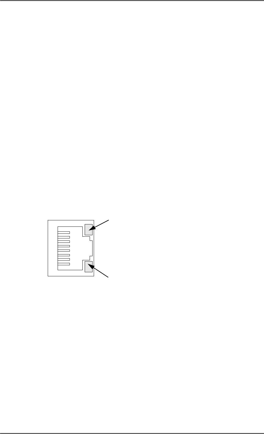
TT-5040A SBU
4-12 Chapter 4: Connectors and pin-out 98-124743-F
4.3 TT-5040A SBU
The TT-5040A SBU provides interfaces for configuration, Aircraft and satcom
interconnections and for the CM.
4.3.1 Connectors on SBU
There are three connectors on the SBU:
• SBU Maintenance connector (front):
Interface to PC for configuration and maintenance purposes.
A 10/100BaseT Ethernet connector with two LED indicators, RJ45 female.
• SBU rear receptacle (top plug and bottom plug):
Interface to Aircraft and satcom interconnections.
An ARINC 404 Shell Size 2 Receptacle.
• Connector for CM (rear, inside connector):
Internal connector used only as interface to the CM.
A female 9-pin Sub-D Connector.
4.3.2 SBU Maintenance connector
Connector drawing
Figure 4-4: SBU Maintenance connector, face view of engaging end
Yellow LED
Activity
Green LED
Link
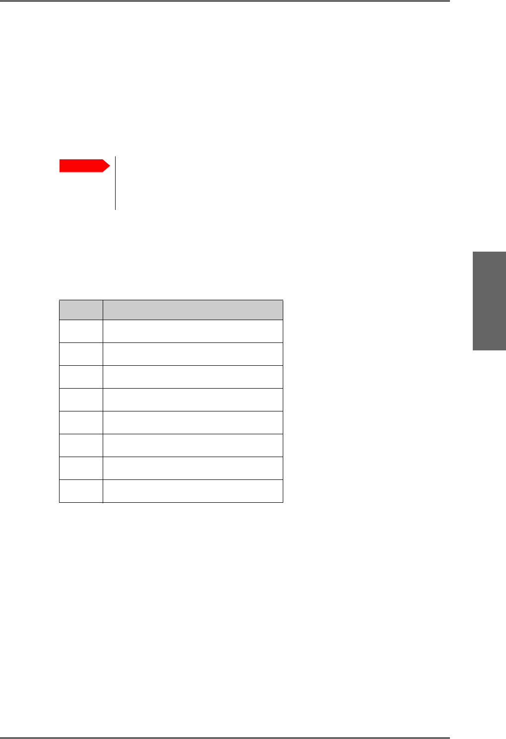
TT-5040A SBU
98-124743-F Chapter 4: Connectors and pin-out 4-13
Connector functions
The front Maintenance interface is 10/100BaseT Ethernet, IEEE802.3.
Use this interface for the following purposes:
• AVIATOR 700 system configuration
• Maintenance
•System software upgrade
Use a standard straight network cable.
For instructions how to configure the AVIATOR 700 system see SBU Configuration tasks
on page 6-12.
Pin-out for SBU Maintenance connector
Important
For systems without the Built-in Router option enabled, i.e. the basic version
or the version with Wireless option: To use the SBU Maintenance connector
disconnect or switch off any PC connected to another LAN interface of the
SBU.
Pin no. Pin Name
FP1 TxD+ input
FP2 TxD- input
FP3 RxD+ output
FP4 Not Used
FP5 Not Used
FP6 RxD- output
FP7 Not Used
FP8 Not Used
Table 4-6: Pin-out for SBU Maintenance connector
(standard Ethernet)
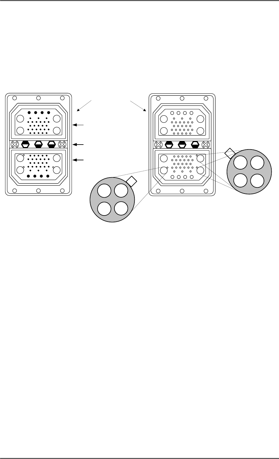
TT-5040A SBU
4-14 Chapter 4: Connectors and pin-out 98-124743-F
4.3.3 SBU rear receptacle
Connector drawing
The following drawing shows the SBU rear receptacle and mating plug.
Figure 4-5: SBU rear receptacle, engaging end (Index code: 19)
7RS3OXJ73,QVHUW
%RWWRP3OXJ%3,QVHUW
,QGH[3LQ&RGH
/LJKWDUHDVDUHNH\KROHV
$$
$$
$ $
$ $
$ $
$ $
$$
$$
9LHZ(QJDJLQJHQG
6%85HDU5HFHSWDFOH 0DWLQJ3OXJLQ7UD\
4XDGUD[(WKHUQHW,QVHUW
LQ$
4XDGUD[(WKHUQHW,QVHUW
LQ$DQG$
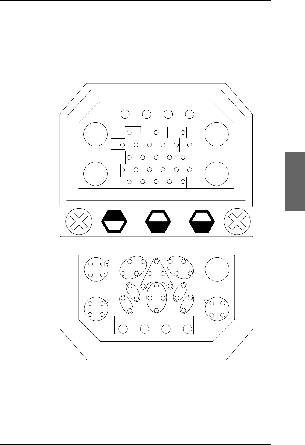
TT-5040A SBU
98-124743-F Chapter 4: Connectors and pin-out 4-15
Connector drawing with functions
The following drawing shows the SBU rear receptacle with pin functions. For wiring details
of this interface see Electrical installation and wiring on page 5-9.
Figure 4-6: SBU rear receptacle with pin functions
$
5)5;
$
:/$1
$
5)7;
$
:/$1
$QQXQFLDWRUV ,6'1
,6'1 566%8&RQWURO
6SDUH,2
:/$1
(QDEOH
$7(
,6'15HVHUYHG
:
:
6%8
(QDEOH
6%8Q21*1'91RWXVHG
/DPSV
LQKLE
5LQJ 5LQJ
7,3 7,3
7[
5[
7[5[
6%8
$
(WKHUQHW
$
*36
$
(WKHUQHW
$
(WKHUQHW
%
$
%
$
1$9 1$9
(WKHUQHW
(WKHUQHW(WKHUQHW
&KDVVLV63$5(
,2
$QQXQFLDWRU63$5(
,2
7[
7[
5[
5[5[
5[
5[
5[
7[
7[
7[
7[
$
7[5[
5[7[
7[5[
5[7[
5[
7[
7[
5[
$
%
$
%
%68,1 %68287
7[
5[
7[5[
,Q
$
,Q
%
2XW
%
2XW
$
1RFRQQHFW
6LJQDO*1'

TT-5040A SBU
4-16 Chapter 4: Connectors and pin-out 98-124743-F
Connector functions, top plug
The top plug of the SBU rear receptacle connects the following signals:
Power & RF Interfaces:
•+28 V DC and GND, Power return
• RF Tx signal to 405038A-002 HSU Tx Coupler
• RF Rx signal from 405038A-003 HSU Rx Power Splitter
• Two RF WLAN antenna connectors (2.4 GHz)
User Interfaces:
• One ISDN, 4-wire connection
• Two analogue 2-wire standard POTS interfaces for Voice/Fax/Modem/secure voice
Control & Maintenance Interfaces:
• RS-422 SBU Control Interface
• Discrete SBU nON input
• Discrete SBU Enable input
• Discrete WLAN Enable input
• Discrete Chime/Lamps Inhibit Input
• 4 configurable Annunciators: #1 (“Incoming call”), #2 (“SBU Failed”) and #3 (“Service
Available”), #4 (“Message received)
• Two ATE Discrete inputs for factory use - Do not connect
•One Discrete Spare I/O
•ISDN #2, Reserved - Do not connect
Connector functions, bottom plug
The bottom plug of the SBU rear receptacle connects the following signals:
Power & RF Interfaces:
• GPS antenna input
•Chassis ground
User Interfaces:
• Six 10/100BaseT Ethernet
Aircraft interfaces:
• Two high or low speed ARINC 429 navigational input
Control & Maintenance Interfaces:
•Two Discrete Spare I/O
• 1 Discrete Output: Message received

TT-5040A SBU
98-124743-F Chapter 4: Connectors and pin-out 4-17
Pin-out for SBU rear receptacle (top plug)
Table 4-7: Pin-out for SBU rear receptacle, top plug
Pin Function
TP A1 RF TX output to 405038A-002 HSU TX
Coupler
TP A2 WLAN antenna #1 (coax)
TP A3 RF RX input from 405038A-003 HSU RX
Power Splitter
TP A4 WLAN antenna #2 (coax)
TP1 SBU +28 V DC Power
TP2 SBU GND, Power Return
TP3 SBU nON, Discrete Input
TP4 Not used
TP5 WLAN Enable, Discrete Input
TP6 2-Wire Voice/Fax/Modem #1 (Ring)
TP7 2-Wire Voice/Fax/Modem #2 (Ring)
TP8 SBU Enable, Discrete Input (active low)
TP9 ATE #1, for factory use - Do not
connect!
TP10 ATE #2, for factory use - Do not
connect!
TP11 2-Wire Voice/Fax/Modem #1 (Tip)
TP12 2-Wire Voice/Fax/Modem #2 (Tip)
TP13 Chime/Lamps Inhibit Input, (Discrete I/O)
TP14 Spare I/O, (Discrete I/O)
TP15 ISDN #2 Tx+ (c) output (TE)
Do not connect!
TP16 ISDN #2 Rx+ (d) input (TE)
Do not connect!
TP17 ISDN #2 Rx- (e) input (TE)
Do not connect!
TP18 ISDN #2 Tx- (f) output (TE)
Do not connect!
TP19 Data bus output to SDU; Output B, RS-422
TP20 Data bus output to SDU; Output A, RS-422
TP21 Data bus input from SDU; Input B, RS-422
TP22 Data bus input from SDU; Input A, RS-422
TP23 ISDN #1 Rx+ (c) input (NT)
TP24 ISDN #1 Tx+ (d) output (NT)
TP25 ISDN #1 Tx- (e) output (NT)
TP26 ISDN #1 Rx- (f) input (NT)
TP27 Annunciator #3, (Discrete I/O, Service
available)
TP28 Annunciator #1, (Discrete I/O, Incoming
call)
TP29 Annunciator #2, (Discrete I/O, SBU fail)
Pin Function

TT-5040A SBU
4-18 Chapter 4: Connectors and pin-out 98-124743-F
Pin-out for SBU rear receptacle (bottom plug)
Table 4-8: Pin-out for SBU rear receptacle, bottom plug
Pin no. Pin name
BP A1.1 Tx+ 10/100BaseT Ethernet #1 (Quadrax
pin 1, Input)
BP A1.2 Rx+ 10/100BaseT Ethernet #1 (Quadrax
pin 2, Output)
BP A1.3 Tx- 10/100BaseT Ethernet #1 (Quadrax
pin 3, Input)
BP A1.4 Rx- 10/100BaseT Ethernet #1 (Quadrax
pin 4, Output)
BP A2.1 Tx+ 10/100BaseT Ethernet #2 (Quadrax
pin 1, Input)
BP A2.2 Rx+ 10/100BaseT Ethernet #2 (Quadrax
pin 2, Output)
BP A2.3 Tx- 10/100BaseT Ethernet #2 (Quadrax
pin 3, Input)
BP A2.4 Rx- 10/100BaseT Ethernet #2 (Quadrax
pin 4, Output)
BP A3.1 Tx+ 10/100BaseT Ethernet #3 (Quadrax
pin 1, Input)
BP A3.2 Rx+ 10/100BaseT Ethernet #3 (Quadrax
pin 2, Output)
BP A3.3 Tx- 10/100BaseT Ethernet #3 (Quadrax
pin 3, Input)
BP A3.4 Rx- 10/100BaseT Ethernet #3 (Quadrax
pin 4, Output)
BP A4 GPS antenna input (coax), Modem,
DC out (SBU stand-alone)
BP1 Annunciator #4 (Discrete I/O, Message
received)
BP2 Spare I/O, (Discrete I/O)
BP3 SBU Chassis Ground
BP4 Spare I/O, (Discrete I/O)
BP5 Data from primary ARINC429
navigational input, A
BP6 Rx- 10/100BaseT Ethernet #4, (Output)
BP7 Data from secondary ARINC429
navigational input, A
BP8 Data from primary ARINC429
navigational input, B
BP9 Data from BSU or CMU, reserved,
ARINC 429 A
BP10 Tx+ 10/100BaseT Ethernet #4, (Input)
BP11 Tx- 10/100BaseT Ethernet #4, (Input)
BP12 Data to BSU or CMU, reserved, ARINC
429 A
BP13 Data from secondary ARINC429
navigational input, B
BP14 Data from BSU or CMU, reserved,
ARINC 429 B
BP15 Common Signal GND for Ethernet
BP16 Rx+ 10/100BaseT Ethernet #4, (Output)
BP17 Common Signal GND for Ethernet
BP18 Data to BSU or CMU, reserved, ARINC
429 B
BP19 Rx- 10/100BaseT Ethernet #5, (Output)
BP20 Tx- 10/100BaseT Ethernet #5, (Input)
BP21 Common Signal GND for Ethernet
BP22 Common Signal GND for Ethernet
BP23 Rx- 10/100BaseT Ethernet #6, (Output)
BP24 Tx- 10/100BaseT Ethernet #6, (Input)
BP25 Tx+ 10/100BaseT Ethernet #5, (Input)
BP26 Rx+ 10/100BaseT Ethernet #5, (Output)
BP27 Common Signal GND for Ethernet
BP28 Tx+ 10/100BaseT Ethernet #6, (Input)
BP29 Rx+ 10/100BaseT Ethernet #6, (Output)
Pin no. Pin name
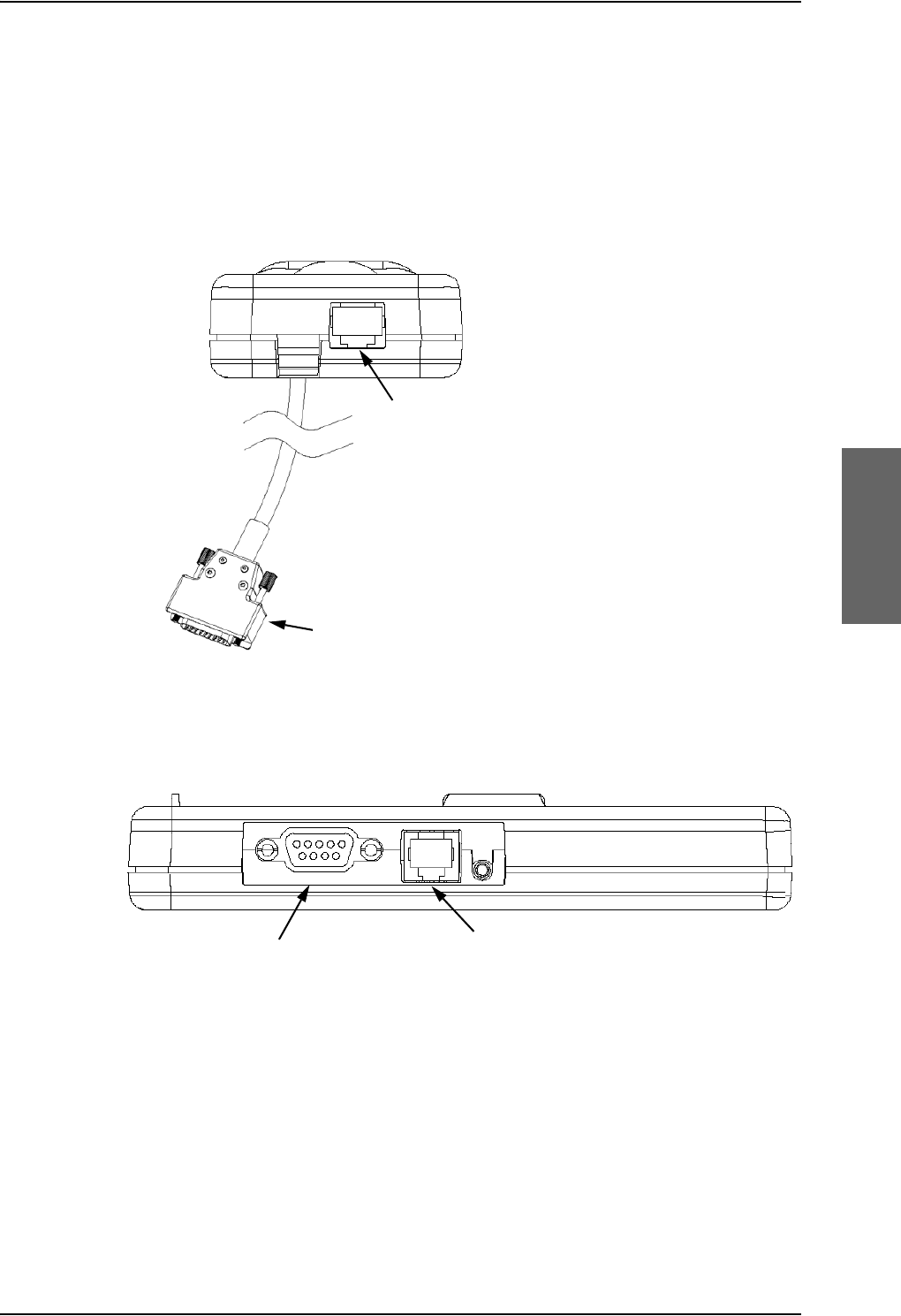
Cradle connectors
98-124743-F Chapter 4: Connectors and pin-out 4-19
4.4 Cradle connectors
4.4.1 Connectors on 4-Wire Cradle
There are four connectors on the 4-Wire Cradle, two on the side of the cradle and two at
the end:
Figure 4-8: 4-Wire Cradle Connectors, Side View of Cradle
Figure 4-7: 4-Wire Cradle Connectors, End View of Cradle
4-Wire Handset connection
SDU connection
2-Wire Voice/Fax/Modem connection
Headset connection

Cradle connectors
4-20 Chapter 4: Connectors and pin-out 98-124743-F
4.4.2 4-wire connector to SDU
Connector drawing
Functions
The 15 pin Sub-D male connector on the short cable at the end of the 4-Wire Cradle
connects the following signals on the SDU:
Handset interface (analog):
• analog 4-wire interface (including +28 V DC Handset supply)
Handset interface (digital):
• RS-485 data interface
Voice/Fax/Modem interface:
• Voice/Fax/Modem/STU-III, analog 2-wire standard POTS interface
OR
Maintenance handset interface:
• Maintenance 4-wire handset connection to SDU front connector
Figure 4-9: 4-Wire Cradle Connector
(DB15M). View: Solder Side
9LHZ6ROGHUVLGH
'%0DOH

Cradle connectors
98-124743-F Chapter 4: Connectors and pin-out 4-21
Pin-out for DB15 connector
The 4-Wire Cradle connector for connection to the SDU has the following pin-out:
Table 4-9: Pin-out for 15 Pin Sub-D Male Connector on short cable in 4-Wire Cradle
Pin Function
12-Wire Tip
(Fax/PC_modem/Auxiliary)
22-Wire Ring
(Fax/PC_modem/Auxiliary)
3GND
4+28 V DC
5 GND, Power Return
6SDU Audio in +
7SDU Audio in -
8GND
9GND
10 RS-485 Data A
11 RS-485 Data B
12 GND
13 SDU Audio out +
14 SDU Audio out -
15 NC
Pin Function
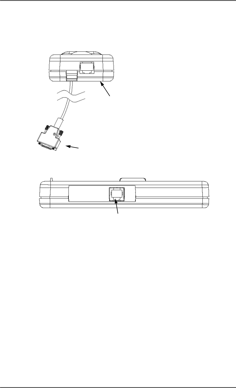
Cradle connectors
4-22 Chapter 4: Connectors and pin-out 98-124743-F
4.4.3 Connectors on 2-Wire Cradle
There are three connectors on the 2-Wire Cradle, one at the side and two at the end:
Figure 4-10: 2-Wire Cradle connectors, end view of cradle
Figure 4-11: TT-5622B 2-Wire Cradle connectors, side view of cradle
2-Wire Handset connection
SDU connection
2-Wire Voice/Fax/Modem/secure voice connection
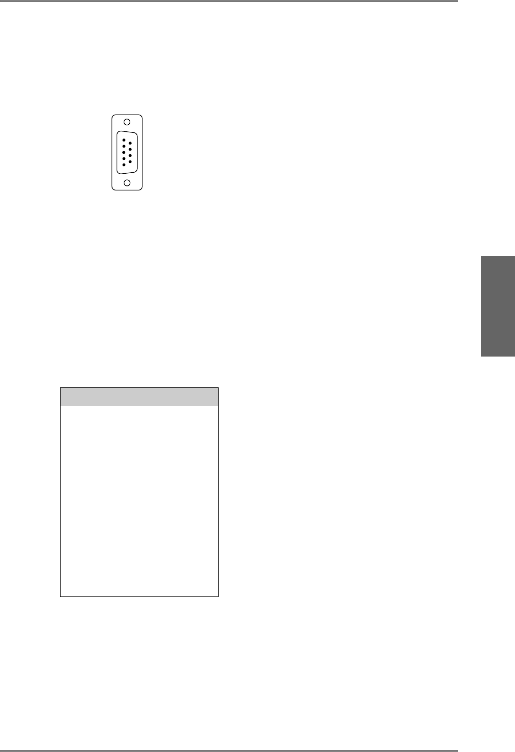
Cradle connectors
98-124743-F Chapter 4: Connectors and pin-out 4-23
4.4.4 2-Wire Cradle connector to SDU or SBU
Connector drawing
Connector functions
The 9 pin Sub-D male connector on the short cable at the end of the 2-Wire Cradle
connects the following signals on the SDU or SBU:
• Analogue 2-wire standard POTS interface for Voice/Fax/Modem/secure voice.
Pin-out for 2-Wire Cradle connector to SBU
The 2-Wire Cradle connector to connect to the SDU has the following pin-out:
The other two connectors are standard POTS RJ11 connectors.
Figure 4-12: 2-Wire Cradle
connector (DB9M). View: Solder side
9LHZ6ROGHUVLGH
'%0DOH
Pin Function
1 Auxiliary Tip
2 Auxiliary Ring
3Shield
4 Not connected
5 Not connected
6 Not connected
7 Not connected
8 Not connected
9 Not connected
Table 4-10: Pin-out for 9 pin Sub-D male
connector in TT-5622B 2-Wire Cradle

Mating connectors in aircraft
4-24 Chapter 4: Connectors and pin-out 98-124743-F
4.5 Mating connectors in aircraft
4.5.1 Connection with SDU
The installation requires the following mating connectors in the aircraft. Note that the SDU
tray holds the mating connector for the SDU rear connector.
Connector Mating Connector Type
Front Panel
Connector
15 pin SUB-D male
Rear Connector ARINC 404 shell size 2 plug with the following contact
arrangements:
Insert A (Top Plug): 33C4
• 4 #16 pin socket contacts
•25 #20HD socket contacts
• 3 #5 coax socket contacts
•1 #5 Quadrax socket contact
Insert B (Bottom Plug): 106
• 106 #22 pin contacts
ITT Cannon Part number DPX2NA-67322-605
Table 4-11: Mating Connectors in Aircraft for SDU
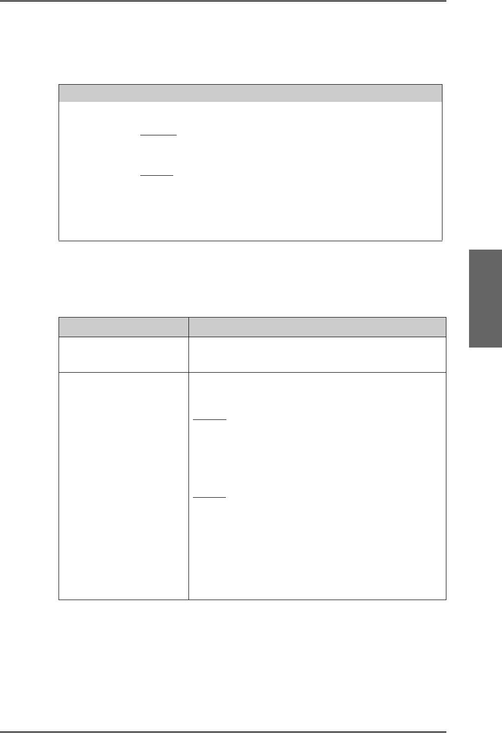
Mating connectors in aircraft
98-124743-F Chapter 4: Connectors and pin-out 4-25
4.5.2 Connection with HPA
The installation tray for the HPA is equipped with the following connector:
4.5.3 Connection with SBU
Note that the SBU tray holds the mating connector for the SBU rear connector.
Table 4-13: Mating connectors in aircraft for SBU
SBU Maintenance connector
(on front panel)
RJ45 male
SBU rear receptacle
(rear connector in the SBU
tray)
ARINC 404 shell size 2 plug with the following contact
arrangements:
Insert A (Top Plug): 33C4
•4 #16 socket contacts
•25 #20 socket contacts
• 4 #5 coax sockets
Insert B (Bottom Plug): 33C4
•4 #16 socket contacts
•25 #20 socket contacts
• 1 #5 coax sockets
•3 #5 quadrax sockets
Part number: DPX2NA-67322-606
Size 5 coax contacts fit for cable type RG-142. For other cable types you must order
suitable contact inserts. For part numbers see Table 5-63 on page 5-84 and Table 5-64 on
page 5-84.
Connector Mating Connector Type
Rear
Connector
ARINC 404 shell size 2 plug with the following contact arrangements:
Insert A (Top Plug): MC2
• 2 #1 coax socket contacts for RG214
Insert B (Bottom Plug): 32C2
• 2 #5 socket contacts for AWG 8-10
• 30 #20 HD socket contacts for AWG 20-24
Radiall part number 616 697 173
Table 4-12: Mating Connector in Aircraft for HPA
Connector Mating connector type

Mating connectors in aircraft
4-26 Chapter 4: Connectors and pin-out 98-124743-F

98-124743-F 5-1
Chapter 5
Installation 5
5.1 General installation information
5.1.1 Overview
This chapter contains considerations and recommendations for installation of the AVIATOR
700 System. Interconnect harness wiring and physical mounting must satisfy all applicable
regulations.
For installation kits for the AVIATOR 700 system contact:
Table 5-1: Installation kits, contact information
The Installation chapter is organized in the following sections:
•Mounting considerations.
This section provides guidelines for the mechanical installation of the units in the
AVIATOR 700 system.
•Electrical installation and wiring.
This section provides wiring drawings and guidelines for the electrical installation of the
AVIATOR 700 system. It also lists the requirements to the cables.
•Recommended cables.
This section provides lists of recommended cables and maximum cable lengths.
•Activation of airtime services
This section provides information how to activate airtime service and details about the
system’s SIM card.
The information, drawings and wiring diagrams contained in this manual are intended as a
reference for engineering planning only. The drawings and wiring diagrams contained
herein do not represent any specific STC. It is the installer’s responsibility to compose
installation drawings specific to the aircraft. This manual and the drawings and wiring
diagrams contained herein may not be used as a substitute for an STC.
To ensure optimal performance from the AVIATOR 700 system, you must
maintain strict adherence to the installation guidelines in this chapter.
Note
Installation kits including wiring can be obtained through ECS (Electronic Cable
Specialists, Inc.) or EMTEQ Inc. For details and order numbers see Installation kits
on page 2-14.
ECS, a Carlisle IT company, USA
Phone (Franklin, WI): +1 800-327-9473
Phone (Kent, WA): +1 800-227-5953
E-mail: sales@CarlisleIT.com
Home page: www.CarlisleIT.com
EMTEQ (B/E Aerospace)
Home page: www.emteq.com
Contact info: www.emteq.com/contact-us.php
Note

General installation information
5-2 Chapter 5: Installation 98-124743-F
5.1.2 Minimum system components
A minimum working system has at least:
•one TT-5035A SDU
• one TT-5035A-001 CM
• one TT-5014A HPA
•one TT-5040A SBU
• one TT-5040A-001 CM
• one TT-5040A-005 SDU to SBU Software interface
• one TT-5038A-002 Tx Coupler
• one TT-5038A-003 Rx Power Splitter
• one handset and cradle, e.g. a TT-5620A 4-Wire Handset and a TT-5622A 4-Wire Cradle
(optional)
• one antenna system with DNLA type F. As antenna system, use either an ARINC 741 or
ARINC 781 compatible system or an HGA-6000, HGA-6500 or HGA-7000 antenna
system.
The following drawing shows the minimum installation required in the AVIATOR 700
system.
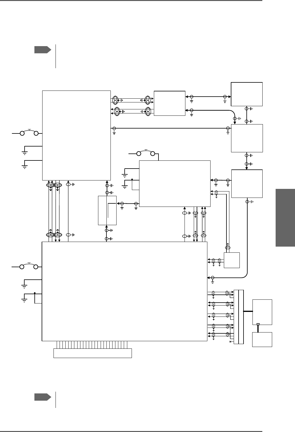
General installation information
98-124743-F Chapter 5: Installation 5-3
Minimum system drawing
This drawing is an overview of which units to connect as a minimum.
For information on other satcom antenna types supported and wiring of the
individual antenna types, refer to the appropriate section of Electrical installation
and wiring on page 5-9 and onwards.
Figure 5-1: AVIATOR 700 minimum system
For navigational input we recommend to use input from an IRS/AHRS navigation system.
Note
77$
6'8
5;3RZHU
6SOLWWHU
77$
73$
5)5;
%3,&$206%
%3
%3
%3
%3
%3
%3
%3
%3
%3
%3
%3
%3
%3
%3
%3
%3
%3
%3
%3
%3
%3
%3
%3,&$2/6%
%3,&$2FRPPRQ
6WUDSSHG,&$2$GGUHVV
73*1'3RZHU5HWXUQ
73
9'&
$LUFUDIW
3RZHU6XSSO\
73
739'&3RZHU
&KDVVLV*URXQGDQG+DQGVHW3RZHU5HWXUQ
5HPRWH212))Q21
77$
+3$
9'&
$LUFUDIW
3RZHU6XSSO\
%3$9'&3RZHU
%3$*1'3RZHU5HWXUQ
%3&KDVVLV
%3
%3
%3
%3
+3$Q21
%3 %3
%3
%3
%3
%3
+3$&21752/
'DWD%,7(
7;&RXSOHU
77$
6'8
+3$
+68
5)7;
5)7;
73
73$
77$
6%8
56
73
73
73
73
73
56
6%8(QDEOH
%3
%3
%3
%3
%3
5)7;
73$
5)5;
73$
'/1$
$5,1&
7\SH)
$&8
$QWHQQD
$5,1&
%3
%3
%3
%3
$7[+6
$5[/6
9'&
$LUFUDIW
3RZHU6XSSO\
73
736%8*1'
%36%8&KDVVLV
5)5;
5)7;
736%8Q21
73
+68
6'8
'/1$
,56$+56$$%3
,56$+56$%%3
,56$+56$$%3
,56$+56$%%3 ,56
77$
+$1'6(7
73
73
$%3
%%3
+L73
/R73
+L73
/R73
)XOO)HDWXUH+DQGVHW56'DWD
&KDVVLV*URXQGDQG+DQGVHW3RZHU5HWXUQ
9'&P$+DQGVHW6XSSO\
+DQGVHW$XGLR2XW&RFNSLW9RLFH$XGLR2XW
+DQGVHW$XGLR,Q&RFNSLW9RLFH$XGLR,Q
73
73
1&
77$
&5$'/(
7ZRZLUHID[PRGHP 7LS
5LQJ
Note
This example includes an ARINC 741 antenna system, but the antenna system
may as well be e.g. an ARINC 781 system or an HGA-7000 antenna.

General installation information
5-4 Chapter 5: Installation 98-124743-F
5.1.3 To upgrade your installation from Aero-HSD+ to AVIATOR 700
The Aero-HSD+ system can be upgraded to an AVIATOR 700 system. To make the upgrade
you replace the HSU with an SBU. The upgrade procedure is described in detail in the
appendix Upgrade from Aero-HSD+ to AVIATOR 700 on page C-1.
Note
For easy access to the system configuration and troubleshooting it is
recommended to connect a Thrane & Thrane 4-Wire Handset.

Mounting considerations
98-124743-F Chapter 5: Installation 5-5
5.2 Mounting considerations
5.2.1 Overview
For optimum system performance, some guidelines on where to install or mount the
components of the AVIATOR 700 system must be followed. Mounting and placement
details are included in this section.
For information on requirements to cables, see the individual sections in Electrical
installation and wiring on page 5-9. For information on recommended cable types and
lengths, see Recommended cables on page 5-81.
5.2.2 SDU
Forced cooling is not required and not recommended.
• Installation in temperature controlled areas and inside or outside pressurized locations
(e.g. avionics bay).
• Mount the SDU where the cooling air holes are not blocked. Note that cooling air holes
in the SDU are placed outside the recommended area for ARINC 404A 3/8 ATR short
units.
•Mount the SDU in an ARINC 404A 3/8 ATR short tray with oval cut-out as shown in
Figure 3-16: Outline Drawing: Tray for SDU and HPA.
• AVIATOR 700D: For safety reasons do not install the 4-wire handset in the
cabin. see also Wiring safety interfaces on page 2-2. Control of the AVIATOR 700D
system is done with the MCDU or via the 4-wire handset installed in the cockpit. It is
possible to log-off the AVIATOR 700D system or change the satellite etc. using the 4-
wire handset. Hereby it is possible to disable the cockpit Data2 functionality using the 4-
wire handset.
5.2.3 SBU
Forced cooling is not required and not recommended.
• Install the SBU in temperature controlled areas and inside or outside pressurized
locations (e.g. avionics bay).
• Mount the SBU in an ARINC 404A 1/4 ATR short tray as shown in Figure 3-
13: Outline drawing: SBU tray: ECS PO299-101 or see SBU trays on page 3-14 for
allowed SBU trays.
5.2.4 Rx Power Splitter
If the Rx Power Splitter is to be mounted on a flat surface, mount it on a 3 mm mounting
plate to provide enough space for mounting of the connectors.
Note
When mounting the units, allow enough space to provide a sufficient bend radius
for the cables. See the cable data sheet for minimum bend radius.
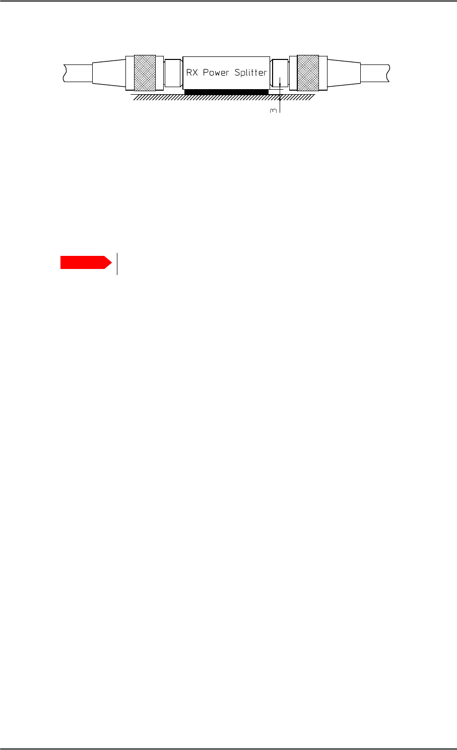
Mounting considerations
5-6 Chapter 5: Installation 98-124743-F
5.2.5 HPA
The HPA can be installed in a non-temperature controlled area.
The HPA is designed with built-in forced cooling (fans).
Internal temperature monitoring prevents damage caused by overheating.
• Mount the HPA vertically on a panel to ensure maximum cooling. Mount the HPA in an
ARINC 404A 3/8 ATR short tray with oval cut-out as shown in Figure 3-16: Outline
Drawing: Tray for SDU and HPA.
• Install the HPA as close to the DLNA as possible.
The cable between the HPA and the DLNA must be a special low-loss coax cable. See
Wiring the satcom antenna on page 5-17 and the wiring drawings on page 5-18 and
page 5-25.
5.2.6 Satcom antenna
In order to steer the satcom antenna towards the satellite, the AVIATOR 700 system needs
to know the position and attitude of the aircraft. Several methods are available to achieve
this.
About satcom antenna steering
•IRS
If IRS is used, the antenna positioning data is computed from the IRS data alone. All
necessary data is available from the IRS. The IRS signal must be connected to both the
SBU and the SDU.
•AHRS & GPS
AHRS does not include all the necessary data, therefore a GPS RF signal must also be
sent to the SBU/SDU. A GPS module is built into the SBU/SDU, it computes the
necessary position and speed information.
AHRS must be connected only to the SDU.
In case the HGA-7000 antenna is used, a GPS antenna is built into the antenna, and the
GPS-RF signal can be fed to the SBU/SDU via the Chelton BSU. See Figure 5-10: Wiring
HGA-7000 antenna system on page 5-28
If another satcom antenna is used, the GPS RF signal may be obtained from a GPS antenna
already installed on the aircraft.
Figure 5-2: Mounting the Rx Power Splitter
Important
Respect the minimum clearance of 25 mm from top and bottom.
Mounting considerations
98-124743-F Chapter 5: Installation 5-7
Satcom antenna types supported
For a list of Cobham SATCOM antenna types supported in the AVIATOR 700 system see
Satcom antenna systems on page 2-8.
An AVIATOR 700 system must only be used with satcom antennas that have received type
approval by Inmarsat.
General mounting considerations
Refer to the satcom antenna manual for instructions and details on mounting the antenna.
Make sure all requirements in the antenna mounting instructions are met.
Place the antenna with unobstructed view to the satellite.
Distance between GPS or Glonass antenna and satcom antenna
Make sure the GPS or Glonass antenna is installed with sufficient distance to the satcom
antenna. For requirements to the radiation distance, refer to the manual for the GPS or
Glonass system.
However, always keep the following distance between the satcom antenna
and the GPS or Glonass antenna:
5.1 m (200 inches)
If the existing GPS or Glonass antenna on board the aircraft does not provide sufficient
filtering of the satcom antenna signal to give a usable GPS or Glonass signal, you must
replace the existing GPS or Glonass antenna with a GPS or Glonass antenna that has a
satcom filter.
Cables between TT-5014A HPA and satcom antenna
We recommend to keep the cable length as short as possible.
Do not bend the cables to a radius smaller than the minimum bend radius stated for the
cables. For further information on cables, see Wiring the satcom antenna on page 5-17 and
Recommended cables on page 5-81.
WARNING! Keep a safety distance of minimum 1.2 m for HGA to the
antenna when the system is transmitting, unless the antenna manual or the
specific system configuration presents different requirements. This safety
distance ensures that a maximum radiation power density of maximum
10 W/m2 is not exceeded (Recommended by the American National Standards
Institute, ANSI/LEEE C95.1-1992).
Note
The antenna installation must be in accordance with the aircraft manufacturers
requirements and/or FAA AC 43.13 - 1B/2A and approved by the appropriate Civil
Aviation Authorities.
Important

Mounting considerations
5-8 Chapter 5: Installation 98-124743-F
5.2.7 WLAN antennas
The recommended WLAN antenna to use with the AVIATOR 700 system is the
TT5040A-004 Wireless Antenna. The WLAN antenna is PMA approved by VT Miltope (P/N
901167-2). You may also use other WLAN antennas approved for aeronautical use.
Cobham SATCOM recommends to use 2 WLAN antennas to get optimum
performance on board.
1. Mount the WLAN-antennas in the aircraft cabin. Install the 2 WLAN antennas in the
same plane (surface).
2. Install the two WLAN antennas with a distance of minimum 12.5 cm (5 inches)
between the two antennas.
3. For optimum performance mount the two antennas at an angle of 90° to each other.
:/$1DQWHQQD
:/$1DQWHQQD
0LQLPXPGLVWDQFH
FPLQFKHV
Figure 5-3: Mounting two WLAN antennas for optimum performance
Make sure the cable loss requirements are met, for further details see in the section Wiring
WLAN antenna interface on page 5-43.
Operating with one WLAN antenna
You can also use a single WLAN antenna. For details how to wire a single WLAN antenna see
Wiring WLAN antenna interface on page 5-43.
Note
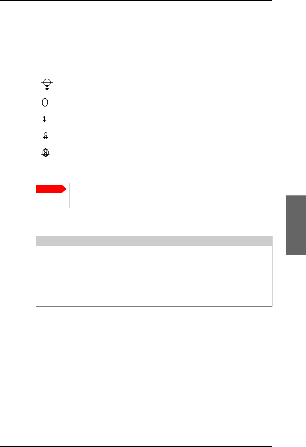
Electrical installation and wiring
98-124743-F Chapter 5: Installation 5-9
5.3 Electrical installation and wiring
5.3.1 Wiring symbols
Throughout the wiring section these common symbols are used:
5.3.2 Wiring SDU to SBU
Coax
Shield
Ground (fuselage)
Twisted
Twisted and shielded
Table 5-2: Wiring symbols
Important
Each wiring drawing in this chapter only shows the connections referred to in
that particular section. Other connections may be required for the system to
work properly.
SDU pin SBU pin Description with reference to SDU
BP56 TP8 SBU Enable
BP73 TP20 Data bus input from SBU; Input A, RS422
BP72 TP19 Data bus input from SBU; Input B, RS422
BP71 TP22 Data bus output to SBU; Output A, RS422
BP70 TP21 Data bus output to SBU; Output B, RS422
Table 5-3: Pins for Wiring SDU to SBU
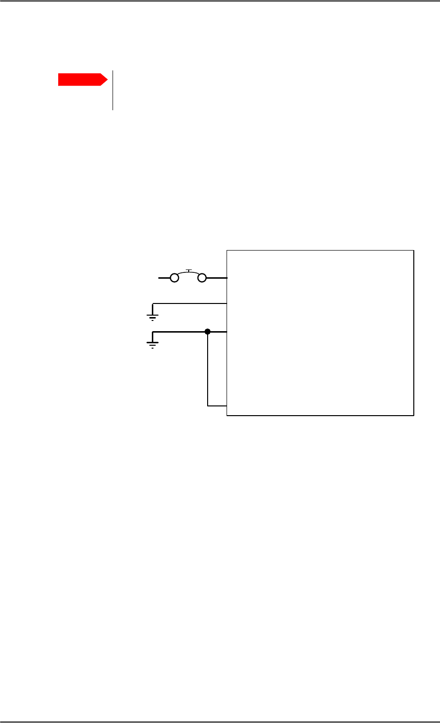
Electrical installation and wiring
5-10 Chapter 5: Installation 98-124743-F
5.3.3 Wiring power supply
Wiring the Satellite Data Unit
The Aircraft Power Bus provides the electric power required to operate the SDU, and a
chassis connection to the aircraft chassis and the installation tray. The +28 V DC Power wire
must include a circuit breaker capable of carrying the required current continuously under
the required environmental conditions.
The following drawing shows the wiring of the SDU power supply.
Requirements to the wiring are stated in the notes on the drawing and in the section Cable
requirements, SDU power supply on page 5-12.
Important
Do not use the same 20 A circuit breaker for both the HPA and the SDU/SBU.
Use a separate circuit breaker for each unit as described in this section, and
with the current rating stated here.
Figure 5-4: Wiring SDU power supply
77$
6'8
>@ 73*1'3RZHU5HWXUQ
73
9'&
$LUFUDIW3RZHU%XV
>@7RWDOUHVLVWDQFHPD[P2KPLQFO&LUFXLW%UHDNHU
>@7RWDOUHVLVWDQFHPD[P2KP
>@'LUHFWO\WR$LUFUDIWFKDVVLVPD[PFDEOHOHQJWKWRSUHYHQW(0&SUREOHPVDQGPD[P2KP
>@5HFRPPHQGHGFLUFXLWEUHDNHU.OL[RQ7&VHULHV$FXUUHQWUDWLQJ
>@,I6$7&202Q2IIVZLWFKLVUHTXLUHG73LVURXWHGWRDQH[WHUQDOVZLWFKWRJURXQG
73
739'&3RZHU
&KDVVLV*URXQGDQG+DQGVHW3RZHU5HWXUQ
5HPRWH212))Q21
>@
$
>@
$:*
>@
>@

Electrical installation and wiring
98-124743-F Chapter 5: Installation 5-11
Pins for SDU power supply
The following list shows the pins used for the SDU power supply.
Description of SDU power supply
+28 V DC Power (TP1)
It is essential to keep the line impedance below the specified limits. See Cable
requirements, SDU power supply on page 5-12.
Reverse polarity protection is only guaranteed if the suggested circuit breaker is used.
Required current capability for the Circuit Breaker: 48 W @ 17.3 V DC which equals
2.8 A DC at the required environmental conditions. A suitable circuit breaker would be
Klixon 2TC series with 4 A current rating.
Chassis Ground / Handset Power Return (TP3)
The Chassis connection makes sure that the HPA cabinet and the installation tray has the
same potential, and that there is a connection from the wiring shields to the cabinet for
EMC purposes.
Connect the wire directly to the installation tray, and to aircraft chassis.
TP3 also connects to the Handset Power Return.
Remote On/Off (nON) input (TP5)
The nON input is used to turn the SDU on and off. Connection of this input to ground turns
on the SDU and all units powered by the SDU.
The electrical specifications are defined like the discrete WOW input type. Please refer to
Discrete type and description: on page 5-68.
Note that when you switch off the SDU, the SBU is indirectly also switched off.
SDU pin Name Description
TP1 +28 V DC Power +28 V DC Power input from Aircraft power bus.
TP2 GND, Power Return Aircraft Ground connection
TP3 Chassis Ground and
Handset Power Return
Chassis connection, connected to installation tray
and Aircraft chassis.
Also used for handset power return.
TP5 Remote ON/OFF (nON) Power On/Off for the SDU and handsets.
Table 5-4: Pins for SDU power supply
Important
Use a separate 4 A circuit breaker for the SDU.

Electrical installation and wiring
5-12 Chapter 5: Installation 98-124743-F
Cable requirements, SDU power supply
Cablea
a. The cable numbers refer to the numbers stated on the wiring drawing in the section Wiring
the Satellite Data Unit on page 5-10.
Max. Resistance Other Requirements
[1]
(+28 V DC)
200 m,
incl. circuit breaker
[2]
(GND, Power Return)
25 mThe cable should be as short as possible.
[3]
(Chassis Ground)
25 mConnect directly to aircraft chassis.
Table 5-5: Requirements to SDU power cables
Note
Maximum cable lengths are calculated and listed in the section Power cables,
allowed cable lengths on page 5-81.
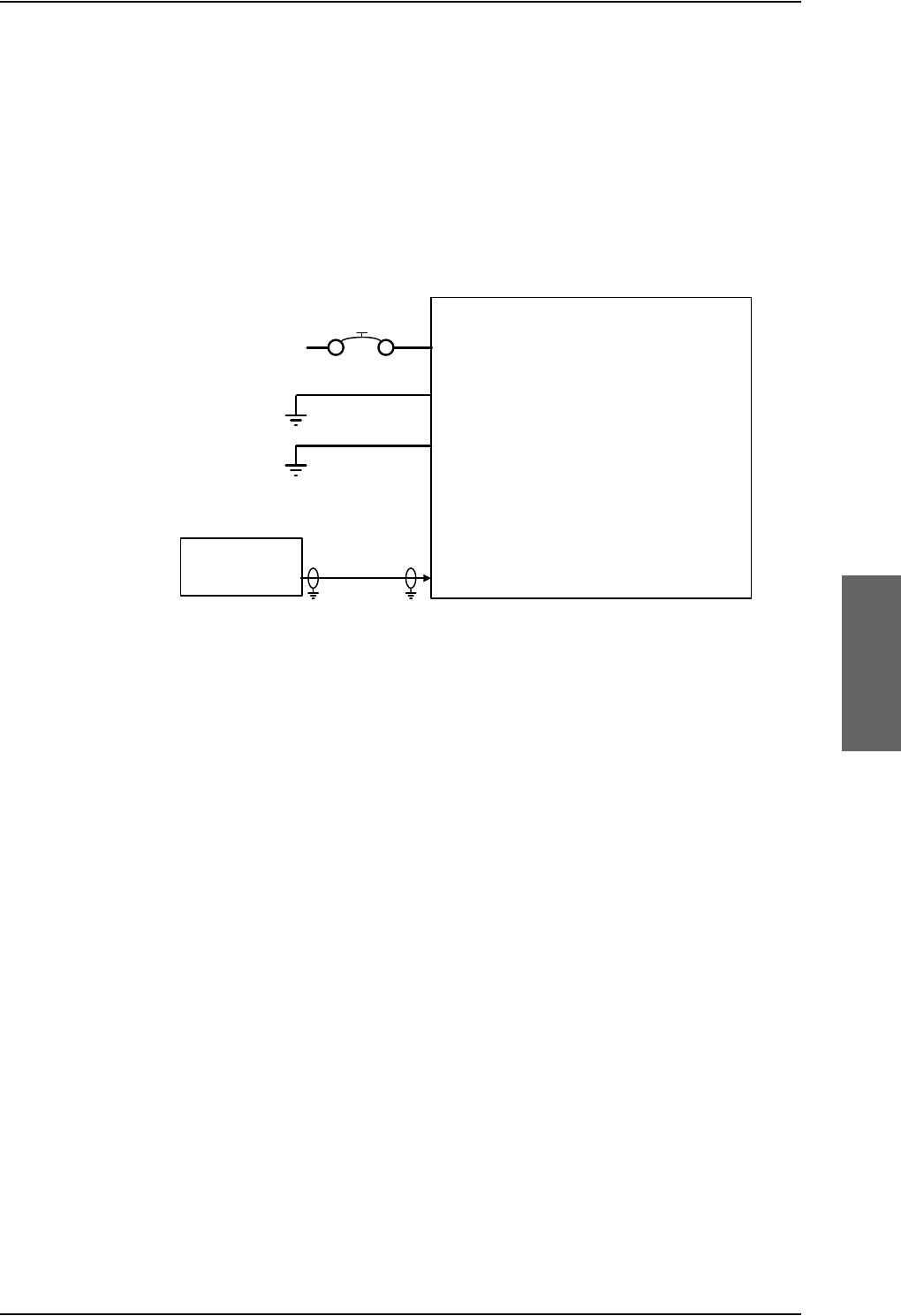
Electrical installation and wiring
98-124743-F Chapter 5: Installation 5-13
Wiring the High Power Amplifier
The Aircraft power bus provides the electric power required to operate the HPA, and a
chassis connection to the aircraft chassis and the installation tray. The +28 V DC Power wire
must include a circuit breaker capable of carrying the required current continuously under
the required environmental conditions.
The following drawing shows the wiring of the HPA power supply.
Requirements to the wiring are stated in the notes on the drawing and in the section Cable
requirements, HPA power supply on page 5-15.
Figure 5-5: Wiring HPA power supply
77$
+3$
>@ %3$*1'3RZHU5HWXUQ
9'&
$LUFUDIW3RZHU%XV
>@7RWDOUHVLVWDQFHPD[P2KPLQFO&LUFXLW%UHDNHU
>@7RWDOUHVLVWDQFHPD[P2KP
>@'LUHFWO\WR$LUFUDIWFKDVVLVPD[PFDEOHOHQJWK$:*WRSUHYHQW(0&SUREOHPVDQG
PD[UHVLVWDQFHP2KP
>@5HFRPPHQGHGFLUFXLWEUHDNHU.OL[RQ7&VHULHV$FXUUHQWUDWLQJ
>@0XVWEHVKLHOGHGWRSUHYHQW(0&SUREOHPV
%3&KDVVLV
%3$9'&3RZHU
%3Q21
>@
$
>@
>@
77$
6'8 %3 >@

Electrical installation and wiring
5-14 Chapter 5: Installation 98-124743-F
Pins for HPA power supply
The following list shows the pins used for the HPA power supply.
Description of HPA power supply
This section describes the installation requirements for HPA power supply interface. The
connection from the HPA to the Aircraft power bus normally goes through the tray
connector. The connector also supports other signals. For information on pin-out, please
refer to TT-5014A High Power Amplifier on page 4-10.
+28 V DC Power
It is essential to keep the line impedance below the specified limits. See Cable
requirements, HPA power supply on page 5-15.
Reverse polarity protection is only guaranteed if the suggested circuit breaker is used.
Required current capability for the Circuit Breaker: 235 W @ 15.7 V DC, which equals
15 A DC, at the required environmental conditions.A suitable circuit breaker would be
Klixon 2TC series with 20 A current rating.
Use a separate 20 A circuit breaker for the HPA.
Chassis (BP30)
The Chassis connection makes sure that the HPA cabinet and the installation tray has the
same potential, and that there is a connection from the wiring shields to cabinet for EMC
purposes.
Connect the wire directly to the installation tray, and to aircraft chassis.
nON (BP6)
The nON input is used by the SDU (BP57) to turn the HPA on and off. The SDU connects
this input to ground to turn on the HPA.
HPA pin Name Description
BP A1 +28 V DC Power +28 V DC Power input from Aircraft power bus.
BP A2 GND, Power Return Aircraft ground connection.
BP30 Chassis Chassis connection, connected to installation tray
and Aircraft chassis.
BP6 nON HPA power on/off controlled by the SDU.
Table 5-6: Pins for HPA power supply
SDU pin Name Description
BP57 HPA remote nON/OFF output Power On/Off control for the HPA.
Table 5-7: Pin for Remote HPA Power on/off by SDU
Important
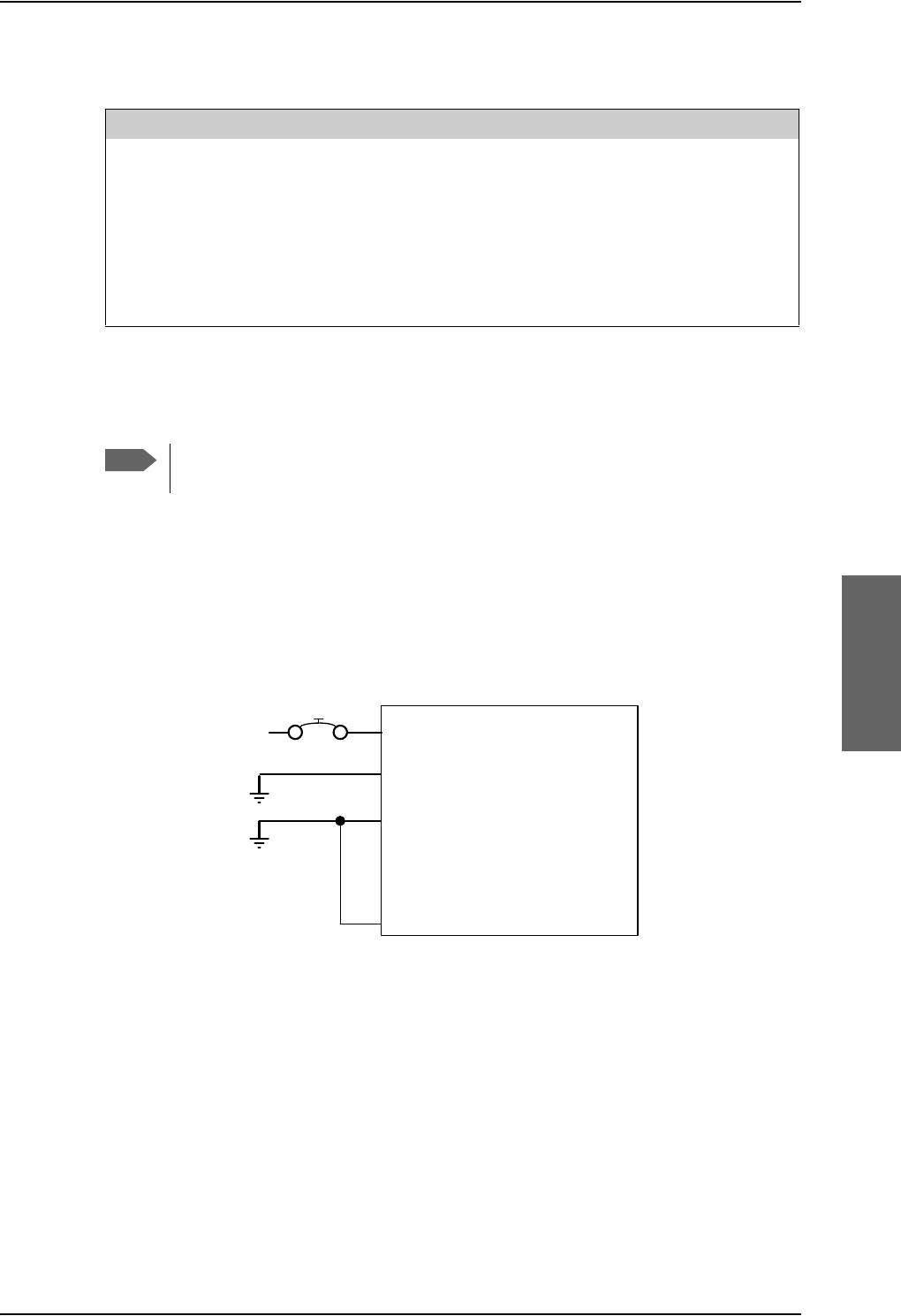
Electrical installation and wiring
98-124743-F Chapter 5: Installation 5-15
Cable requirements, HPA power supply
Wiring the SwiftBroadband Unit
The Aircraft power bus interfaces supply the electric power required to operate the SBU.
They also supply a chassis connection to the aircraft chassis and the installation tray for
EMC purposes. The +28 V DC Power wire must include a circuit breaker capable of carrying
the required current continuously under the required environmental conditions.
The following drawing shows the wiring of the SBU to the Aircraft Power Bus.
SBU maximum power consumption
In the AVIATOR 700 system the SBU does not supply power for neither the HPA nor
external satcom antennas. See Table A-3 on page A-6 for the total power consumption of
the SBU (including CM).
Cablea
a. The cable numbers refer to the numbers stated on the wiring drawing in the section Wiring
the High Power Amplifier on page 5-13.
Max. Resistance Other Requirements
[1] (+28 V DC Power) 100 m,
incl. circuit breaker
[2] (GND, Power Return) 25 m
[3] (Chassis) 25 mConnect directly to aircraft chassis.
[5] (nON) - Must be shielded to avoid EMC
problems.
Table 5-8: Requirements to HPA power cables
Note
Maximum cable lengths are calculated and listed in the section Power cables,
allowed cable lengths on page 5-81.
Figure 5-6: Wiring SBU power supply
77$
6%8
>@ 73*1'3RZHU5HWXUQ
9'&
$LUFUDIW3RZHU%XV
>@7RWDOUHVLVWDQFHPD[P2KPLQFO&LUFXLW%UHDNHU
>@'LUHFWO\WR$LUFUDIW*URXQGZLWKOHVVWKDQPFDEOH7RWDOUHVLVWDQFHPD[P2KP
>@'LUHFWO\WRLQVWDOODWLRQWUD\DQGDLUFUDIWFKDVVLVPD[P2KPUHVLVWDQFH
>@5HFRPPHQGHGFLUFXLWEUHDNHU.OL[RQ7&VHULHV$FXUUHQWUDWLQJ
>@,I6$7&202Q2IIVZLWFKLVUHTXLUHG73LVURXWHGWRDQH[WHUQDOVZLWFKWRJURXQG
%3
739'&3RZHU
&KDVVLV*URXQG
>@
$
>@
>@
73 6%8Q21212))
>@

Electrical installation and wiring
5-16 Chapter 5: Installation 98-124743-F
Pins for SBU power supply
The following list shows the pins used for the SBU power supply.
Description of SBU power supply
+28 V DC Power
It is essential to keep the line impedance below the specified limits. See Cable
requirements, SBU power supply on page 5-17.
Reverse polarity protection is only guaranteed if the suggested circuit breaker is used. A
suitable circuit breaker with sufficiently low resistance would be Klixon 2TC series with
7.5 A current rating.
Use a separate 7.5 A circuit breaker for the SBU.
Chassis Ground (BP3)
The Chassis connection ensures that the SBU cabinet and the installation tray have the
same potential, and that there is a connection from the cable shields to the cabinet to
comply with EMC requirements.
Connect the wire directly to the installation tray and to aircraft chassis.
Remote ON/OFF - SBU nON, Discrete Input (TP3)
The nON input is used to turn the SBU on and off. Connection of this input to ground turns
on the SBU and all units powered by the SBU.
The electrical specifications are defined in Description of the discrete types on page 5-68.
SBU pin Name Description
TP1 +28 V DC Power +28 V DC Power input from Aircraft power bus.
TP2 GND, Power Return Aircraft Ground connection
BP3 Chassis Ground Chassis connection, connected to installation tray
and Aircraft chassis.
TP3 SBU nOn, Discrete Input Power On/Off for the SBU and units powered by
the SBU
Table 5-9: Pins for SBU power supply
Important
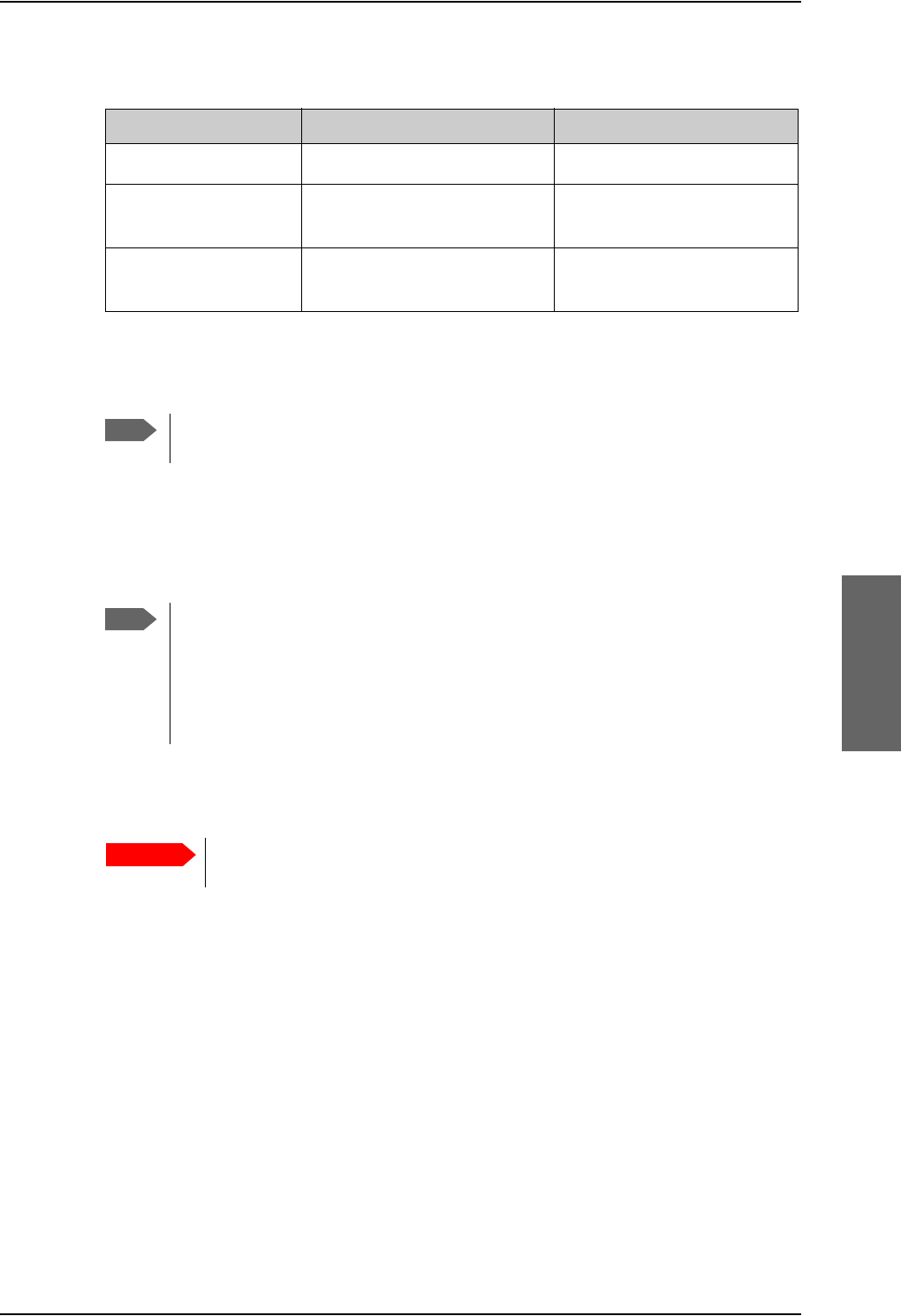
Electrical installation and wiring
98-124743-F Chapter 5: Installation 5-17
Cable requirements, SBU power supply
5.3.4 Wiring the satcom antenna
Cable losses
Selection of DLNA
Use the 405013A DLNA Type F.
The DLNA used in the AVIATOR 700 system must contain improved Tx-
filtering for protection of the GNSS and Iridium band.
Cablea
a. The cable numbers refer to the numbers stated on the wiring drawing in the section Figure
5-6: Wiring SBU power supply.
Max. resistance Other requirements
[1] (+28 V DC Power) 250 m, incl. circuit breaker
[2] (GND, Power Return) 25 mThe cable should be as short
as possible, max. 1 m.
[3] (Chassis Ground) 25 mConnect directly to aircraft
chassis.
Table 5-10: Requirements to SBU power cables
Note
For maximum allowed cable lengths, see Power cables, allowed cable lengths on
page 5-81.
Note
During installation, measure and write down the cable loss of the RF cables. You
need these values later on for the SDU in the Aero-SDU Configuration Program
and for the SBU in the web interface during configuration of the system. For
further details see Basic configuration of the SDU on page 6-9 or the online help
in the Aero-SDU Configuration Program and Configure RF settings of the SBU on
page 6-50.
Important
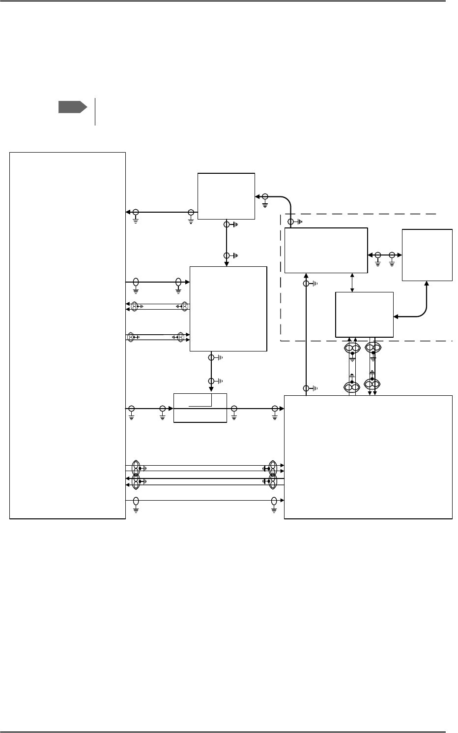
Electrical installation and wiring
5-18 Chapter 5: Installation 98-124743-F
Wiring ARINC 741 antenna systems
An example of an ARINC 741 antenna system is the AMT-50 system. The following
drawing shows the wiring for an AVIATOR 700 system using an AMT-50 antenna.
Note
In an AVIATOR 700 system, the DLNA must be ARINC 781 Type F compatible and
contain extra TX-filtering for protection of the GNSS and Iridium band.
Figure 5-7: Wiring AMT-50 Subsystem
7;&RXSOHU
77$>@
77$
6'8
$07
$QWHQQD
$5,1&
7\SH)
'/1$
3RZHU
6SOLWWHU
G%#*+]
+68
6'8
'/1$
5;3RZHU6SOLWWHU
77$
77$
6%8
6%8&RQWURO56
%3
%3
%3
%3
%3
73
73
73
73
73
6%8&RQWURO56
6%8(QDEOH
73$
73$
6'8
RXW
+3$
LQ
+68
73
77$
+3$
73
%3
%3
%3
%3
+3$Q21
%3 %3
%3
%3
%3
%3
+3$&21752/
'DWD%,7(
73$
73$
5)5;&2$;>@>@
5)5;&2$;>@
: >@
5)7;&2$;>@
5)7;&2$;
>@>@ 5)7;&2$;>@
5)5;&2$;>@
$07
$&8
$%*+
:
>@>@
%3
%3
%3
%3
$7[+6
$5[/6
$076XEV\VWHP
:D
:E
:F
:F
:D :E
>@7KHFDEOHORVVRI:EHWZHHQ'/1$DQGDQWHQQDPXVWEH WRG%#*+]
>@7KHWRWDOFDEOHORVVRI:'/1$ORVV:PXVWEH WRG%#*+]
>@7KHWRWDOFDEOHORVVRI:D6SOLWWHUORVV:EPXVWEH WRG%#*+]
>@7KHWRWDOFDEOHORVVRI:D6SOLWWHUORVV:FPXVWEH WRG%#*+]
>@7KHWRWDOFDEOHORVVRI:D:EPXVWEH WRG%#*+]
>@7KHFDEOHORVVHVRI:DDQG:FPXVWEHHTXDOZLWKLQG%#*+]
>@1RWHWKDWLQDQGRXWDUHZLUHGLQYHUVH

Electrical installation and wiring
98-124743-F Chapter 5: Installation 5-19
Pins for ARINC 741 antenna system
The following lists show the SBU, SDU and HPA pins in the AVIATOR 700 system used for
connecting an ARINC 741 antenna system.
SBU pin Description
TP A1 RF Tx output to Tx Coupler (HSU port)
TP A3 RF Rx input from Rx Power Splitter (HSU port)
TP8 SBU Enable input (active low)
TP19 Data bus output to SDU; Output B, RS-422
TP20 Data bus output to SDU; Output A, RS-422
TP21 Data bus input from SDU; Input B, RS-422
TP22 Data bus input from SDU; Input A, RS-422
Table 5-11: SBU Pins for AMT-50 antenna subsystem
SDU pin Description
TP A1 RF Rx input from Rx Power Splitter (SDU port)
TP A2 RF Tx output to Tx Coupler (SDU port)
BP70 Data bus output to SBU; Output B, RS-422
BP71 Data bus output to SBU; Output A, RS-422
BP72 Data bus input from SBU; Input B, RS-422
BP73 Data bus input from SBU; Input A, RS-422
BP56 SBU Enable output
BP57 HPA remote nOn/Off output
BP78 HPA Control Output A, RS-422
BP79 HPA Control Output B, RS-422
BP80 HPA Data/BITE Input A, RS-422
BP81 HPA Data/BITE Input B, RS-422
Table 5-12: SDU Pins for AMT-50 antenna subsystem

Electrical installation and wiring
5-20 Chapter 5: Installation 98-124743-F
Description of control interfaces
SBU control interface (TP19-TP22)
The RS-422 control interface on SBU pins TP19-TP22 is used by the SDU to control the
SBU. The SBU operates as a slave to the SDU.
HPA ARINC 429 interface (BP8, BP9, BP13, BP14 on HPA)
An ARINC 429 high speed Tx interface and an ARINC 429 low speed Rx interface is used for
communication between the HPA and the AMT-50 ACU.
SBU Enable (TP8)
The SDU uses the SBU Enable input to reset and inhibit the transmitter output signal from
the SBU. The electrical specification is defined as for the discrete Weight-On-Wheels input
type. If TP8 is not connected to the SDU pin, the SBU stays in reset state.
HPA pin Description
TP1 RF Tx output to DLNA
TP2 RF Tx input from Tx Coupler
BP6 Remote nOn/Off input from SDU
BP8 A429 Tx A output to ACU/BSU
BP9 A429 Tx B output to ACU/BSU
BP13 A429 Rx1 A input from ACU/BSU
BP14 A429 Rx1 B input from ACU/BSU
BP25 Tx Data/BITE Output A, RS-422, to SDU
BP26 Tx Data/BITE Output B, RS-422, to SDU
BP27 Rx Control Input A, RS-422, from SDU
BP28 Rx Control Input B, RS-422, from SDU
Table 5-13: HPA Pins for ARINC 741 antenna system

Electrical installation and wiring
98-124743-F Chapter 5: Installation 5-21
RF cable requirements, ARINC 741 antenna system
ARINC 429 cable and RS-422 SBU control interface cable requirements
The cables for these interfaces must be twisted and shielded and conform to the standards
for aeronautical use.
For recommended cable types, see Recommended cables for ARINC 429 on page 5-85
and Recommended cables for RS-422 SBU control interface on page 5-85.
Cablea
a. The “W” cable numbers refer to the numbers stated on the wiring drawing in Figure 5-
7: Wiring AMT-50 Subsystem.
Min. Cable Loss @1.6 GHz Max. Cable Loss@1.6 GHz
W3
(DLNA to Antenna)
0 dB 0.3 dB
W3 + DLNA loss + W4 0 dB Total: 2.6 dB
W5a + Splitter loss + W5b 6 dB 29 dB
W5a + Splitter loss + W5c 6 dB 25 dB
W6a + W6b 0 dB 11 dB
W6a, W6c The cable losses of W6a and W6c must be equal within ±2.5
dB
Table 5-14: Requirements to RF Cables, ARINC 741 antenna systems
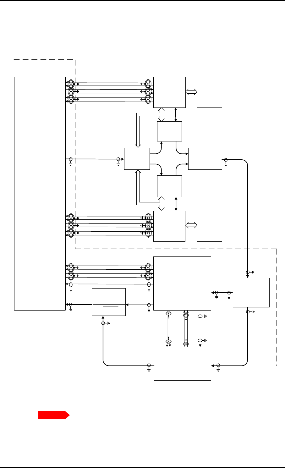
Electrical installation and wiring
5-22 Chapter 5: Installation 98-124743-F
Wiring ARINC 741 dual side panel antenna system
The following drawing shows the wiring of an ARINC 741 dual side panel antenna system.
Figure 5-8: Wiring ARINC 741 dual side panel antenna system
77$
+3$
$5[$%3
$5[%%3
$7[$%3
$7[%%3
+3$0XWH$%3
+3$0XWH%%3
%68
67%2
$5[$%3
$5[%%3
$7[$%3
$7[%%3
+3$0XWH$%3
+3$0XWH%%3
%68
3RUW
:
;
7
8
*
+
:
;
7
8
*
+
'/1$
3RUW
$QW
+35
7[ 5[
'/1$
67%2
$QW
7[ 5[
5)7[RXWSXW73
+*$
3RUW
+*$
67%2
77$
6'8
73$
$9,$725
6\VWHP
%3
%3
%3
%3
+3$Q21
%3 %3
%3
%3
%3
%3
+3$&21752/
'DWD%,7(
73$
73 5)7[
5)5[
&RPELQHU
$5,1&'XDO6LGH3DQHO$QWHQQD6\VWHP
77$
6%8
5[3RZHU
6SOLWWHU
77$
7[&RXSOHU
77$
5)7[
5)5[
5)5[
5)7[
6%8&RQWURO56
73
73
73
73
73
6%8&RQWURO56
6%8(QDEOH
%3
%3
%3
%3
%3
>@1RWHWKDWLQDQGRXWDUHZLUHGLQYHUVH
LQ RXW >@
73$
73$
Important
Remember to select ARINC741 Dual Panel Antenna in the Configuration
program under Installation > RF > Antenna > Type, and to write down the
cable losses. See Cable losses on page 5-17.

Electrical installation and wiring
98-124743-F Chapter 5: Installation 5-23
Pins for Dual Side Panel antenna system
The following list shows the pins in the AVIATOR 700 system used for connecting a Dual
Side Panel antenna system.
HPA pin Name/Description
TP1 RF Tx output to HPR
TP2 RF Tx input from SDU
BP6 Remote nOn/Off input from SDU
BP8 A429 Tx A output to BSU (Port)
BP9 A429 Tx B output to BSU (Port)
BP10 A429 Tx A output to BSU (STBO)
BP11 A429 Tx B output to BSU (STBO)
BP13 A429 Rx1 A input from BSU (Port)
BP14 A429 Rx1 B input from BSU (Port)
BP15 A429 Rx2 A input from BSU (STBO)
BP16 A429 Rx2 B input from BSU (STBO)
BP17 HPA Mute 1 A input from BSU (Port)
BP18 HPA Mute 1 B input from BSU (Port)
BP19 HPA Mute 2 A input from BSU (STBO)
BP20 HPA Mute 2 B input from BSU (STBO)
BP25 Tx Data/BITE Output A, RS-422, to SDU
BP26 Tx Data/BITE Output B, RS-422, to SDU
BP27 Rx Control Input A, RS-422, from SDU
BP28 Rx Control Input B, RS-422, from SDU
Table 5-15: HPA pins for dual side panel antenna system

Electrical installation and wiring
5-24 Chapter 5: Installation 98-124743-F
SDU pin Name/Description
TP A1 RF Rx input from RX Power Splitter (SDU port)
TP A2 RF Tx output to Tx Coupler (SDU port)
BP56 SBU Enable output (active low)
BP57 HPA remote nOn/Off output
BP70 Data bus output to SBU; Output B, RS-422
BP71 Data bus output to SBU; Output A, RS-422
BP72 Data bus input from SBU; Input B, RS-422
BP73 Data bus input from SBU; Input A, RS-422
BP78 HPA Control Output A, RS-422
BP79 HPA Control Output B, RS-422
BP80 HPA Data/BITE Input A, RS-422
BP81 HPA Data/BITE Input B, RS-422
Table 5-16: SDU pins for dual side panel antenna system
SBU pin Description
TP A1 RF Tx output to Tx Coupler (HSU port)
TP A3 RF Rx input from Rx Power Splitter (HSU port)
TP8 SBU Enable input
TP19 Data bus output to SDU; Output B, RS-422
TP20 Data bus output to SDU; Output A, RS-422
TP21 Data bus input from SDU; Input B, RS-422
TP22 Data bus input from SDU; Input A, RS-422
Table 5-17: SBU pins for dual side panel antenna system
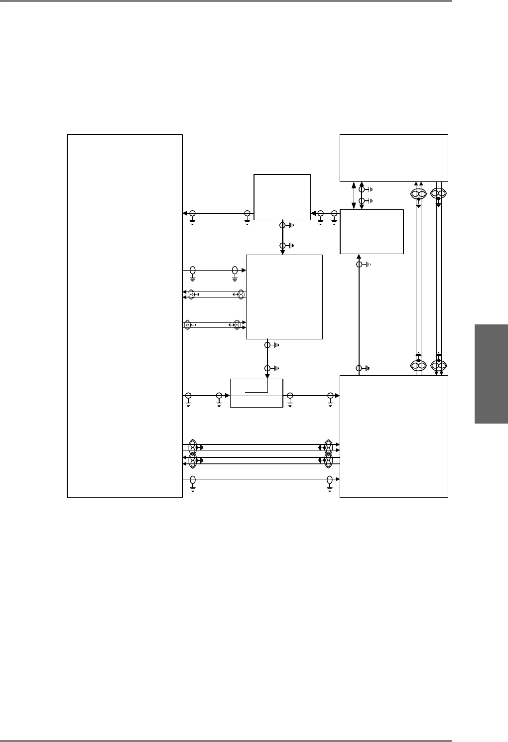
Electrical installation and wiring
98-124743-F Chapter 5: Installation 5-25
Wiring ARINC 781 antenna systems
The following drawing shows the wiring for an AVIATOR 700 system using an ARINC 781
antenna system.
Requirements to the cables are stated on the drawing and in the next section RF cable
requirements, ARINC 781 antenna systems.
Figure 5-9: Wiring ARINC 781 antenna system
7;&RXSOHU
77$>@
77$
6'8
$5,1&$QWHQQD
$5,1&
7\SH)
'/1$
3RZHU
6SOLWWHU
G%#*+]
+68
6'8 '/1$
5;3RZHU6SOLWWHU
77$
77$
6%8
6%8&RQWURO56
%3
%3
%3
%3
%3
73
73
73
73
73
6%8&RQWURO56
6%8(QDEOH
73$
73$
6'8
RXW>@
+3$
LQ
+68
73
77$
+3$
73
%3
%3
%3
%3
+3$Q21
%3 %3
%3
%3
%3
%3
+3$&21752/
'DWD%,7(
73$
73$
5)5;&2$;
>@>@
5)5;&2$;>@
: >@
5)7;&2$;>@
5)7;&2$;
>@>@ 5)7;&2$;>@
5)5;&2$;>@
>@7KHFDEOHORVVRI:EHWZHHQ'/1$DQGDQWHQQDPXVWEH WRG%#*+]
>@7KHWRWDOFDEOHORVVRI:'/1$ORVV:PXVWEH WRG%#*+]
>@7KHWRWDOFDEOHORVVRI:D6SOLWWHUORVV:EPXVWEH WRG%#*+]
>@7KHWRWDOFDEOHORVVRI:D6SOLWWHUORVV:FPXVWEH WRG%#*+]
>@7KHWRWDOFDEOHORVVRI:D:EPXVWEH WRG%#*+]
>@7KHFDEOHORVVHVRI:DDQG:FPXVWEHHTXDOZLWKLQG%#*+]
>@1RWHWKDWLQDQGRXWDUHZLUHGLQYHUVH
:>@>@
:E :D
:F
:F
:D :E
%3
%3
%3
%3
$7[+6
$5[/6

Electrical installation and wiring
5-26 Chapter 5: Installation 98-124743-F
Pins for ARINC 781 antenna system
The following lists show the SBU, SDU and HPA pins in the AVIATOR 700 system used for
connecting an ARINC 781 antenna system.
SBU pin Description
TP A1 RF Tx output to Tx Coupler (SBU port)
TP A3 RF Rx input from Rx Power Splitter (SBU port)
TP8 SBU Enable input (active low)
TP19 Data bus output to SDU; Output B, RS-422
TP20 Data bus output to SDU; Output A, RS-422
TP21 Data bus input from SDU; Input B, RS-422
TP22 Data bus input from SDU; Input A, RS-422
Table 5-18: SBU pins for ARINC 781 antenna system
SDU pin Description
TP A1 RF Rx input from Rx Power Splitter (SDU port)
TP A2 RF Tx output to Tx Coupler (SDU port)
BP70 Data bus output to SBU; Output B, RS-422
BP71 Data bus output to SBU; Output A, RS-422
BP72 Data bus input from SBU; Input B, RS-422
BP73 Data bus input from SBU; Input A, RS-422
BP56 SBU Enable output
BP57 HPA remote nOn/Off output
BP78 HPA Control Output A, RS-422
BP79 HPA Control Output B, RS-422
BP80 HPA Data/BITE Input A, RS-422
BP81 HPA Data/BITE Input B, RS-422
Table 5-19: SDU pins for ARINC 781 antenna system

Electrical installation and wiring
98-124743-F Chapter 5: Installation 5-27
HPA pin Description
TP1 RF Tx output to DLNA
TP2 RF Tx input from Tx Coupler (HPA port)
BP6 Remote nOn/Off input from SDU
BP8 A429 Tx A output to ARINC 781 antenna
BP9 A429 Tx B output to ARINC 781 antenna
BP13 A429 Rx1 A input from ARINC 781 antenna
BP14 A429 Rx1 B input from ARINC 781 antenna
BP25 Tx Data/BITE Output A, RS-422, to SDU
BP26 Tx Data/BITE Output B, RS-422, to SDU
BP27 Rx Control Input A, RS-422, from SDU
BP28 Rx Control Input B, RS-422, from SDU
Table 5-20: HPA pins for ARINC 781 antenna system
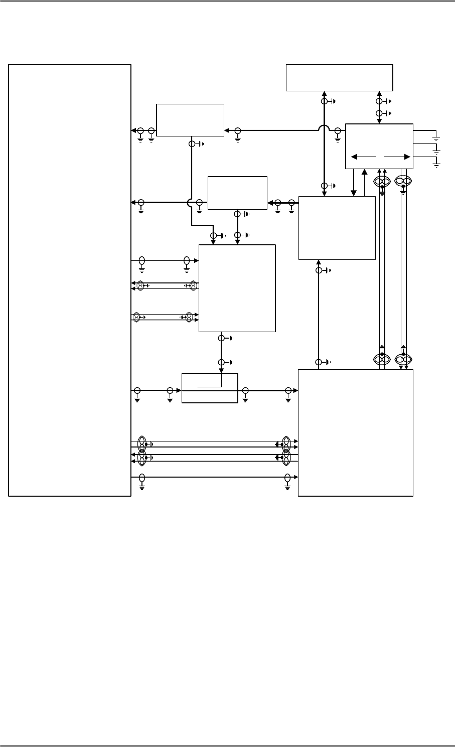
Electrical installation and wiring
5-28 Chapter 5: Installation 98-124743-F
Wiring HGA 7000 antenna system
Figure 5-10: Wiring HGA-7000 antenna system
7;&RXSOHU
77$
77$
6'8
%68
$5,1&
7\SH)
'/1$
3RZHU6SOLWWHU5;
G%#*+]
+68
6'8 '/1$
5;3RZHU6SOLWWHU
77$
77$
6%8
6%8&RQWURO56
%3
%3
%3
%3
%3
73
73
73
73
73
6%8&RQWURO56
6%8(QDEOH
73$
73$
6'8
RXW
+3$
LQ
+68
73
77$
+3$
73
%3
%3
%3
%3
+3$Q21
%3 %3
%3
%3
%3
%3
+3$&21752/
'DWD%,7(
73$
73$
5)5;&2$;
>@>@
5)5;&2$;>@
:
>@
5)7;&2$;>@
5)7;&2$;
>@>@ 5)7;&2$;>@
5)5;&2$;>@
>@ 7KHFDEOHORVVRI:EHWZHHQ'/1$DQGDQWHQQDPXVWEH WRG%#*+]
>@ 7KHWRWDOFDEOHORVVRI:'/1$ORVV:PXVWEH WRG%#*+]
>@ 7KHWRWDOFDEOHORVVRI:D6SOLWWHUORVV:EPXVWEH WRG%#*+]
>@ 7KHWRWDOFDEOHORVVRI:D6SOLWWHUORVV:FPXVWEH WRG%#*+]
>@ 7KHWRWDOFDEOHORVVRI:D:EPXVWEH WRG%#*+]
>@ 7KHFDEOHORVVHVRI:DDQG:FPXVWEHHTXDOZLWKLQG%#*+]
>@ *36FDEOHV:E:FDQG:GPXVWEHZLUHGLI$+56LVXVHGLQVWHDGRI,56
&DEOH:DPXVWEHZLUHGLQERWKFDVHV
7KHWRWDOFDEOHORVVHVRI:D:E:FPXVWEH WRG%#*+]
7KHWRWDOFDEOHORVVHVRI:D:E:GPXVWEH WRG%#*+]
:
>@>@
:E
:D
:F
:F
:D :E
%3
%3
%3
%3
$7[+6
$5[/6
:; +-
-
-
%+
-
-
/Y
$17
7;
+*$
5;
3RZHU6SOLWWHU*36
G%#*+]
+68
6'8 '/1$
5;3RZHU6SOLWWHU
77$ :D
:E
>@
:F
>@
-EOXH -UHG
:G
>@
73$
%3$
I
L
Q
>@

Electrical installation and wiring
98-124743-F Chapter 5: Installation 5-29
Pins for HGA-7000 antenna system
The following lists show the SBU, SDU and HPA pins in the AVIATOR 700 system used for
connecting an HGA 7000 antenna system.
SBU pin Description
TP A1 RF Tx output to Tx Coupler (SBU port)
TP A3 RF Rx input from Rx Power Splitter (SBU port)
TP8 SBU Enable input (active low)
TP19 Data bus output to SDU; Output B, RS-422
TP20 Data bus output to SDU; Output A, RS-422
TP21 Data bus input from SDU; Input B, RS-422
TP22 Data bus input from SDU; Input A, RS-422
BP A4 Input from Power Splitter (GPS) (HSU port)
Table 5-21: SBU pins for HGA 7000 antenna system
SDU pin Description
TP A1 RF Rx input from Rx Power Splitter (SDU port)
TP A2 RF Tx output to Tx Coupler (SDU port)
BP70 Data bus output to SBU; Output B, RS-422
BP71 Data bus output to SBU; Output A, RS-422
BP72 Data bus input from SBU; Input B, RS-422
BP73 Data bus input from SBU; Input A, RS-422
BP56 SBU Enable output
BP57 HPA remote nOn/Off output
BP78 HPA Control Output A, RS-422
BP79 HPA Control Output B, RS-422
BP80 HPA Data/BITE Input A, RS-422
BP81 HPA Data/BITE Input B, RS-422
Table 5-22: SDU pins for HGA 7000 antenna system

Electrical installation and wiring
5-30 Chapter 5: Installation 98-124743-F
Description of control interfaces
SBU control interface (TP19-TP22)
The RS-422 control interface on SBU pins TP19-TP22 is used by the SDU to control the
SBU. The SBU operates as a slave to the SDU.
HPA ARINC 429 interface (BP8, BP9, BP13, BP14 on HPA)
An ARINC 429 high speed Tx interface and an ARINC 429 low speed Rx interface is used for
communication between the HPA and the internal BSU of the ARINC 781 antenna.
SBU Enable (TP8)
The SDU uses the SBU Enable input to reset and inhibit the transmitter output signal from
the SBU. The electrical specification is defined as for the discrete Weight-On-Wheels input
type. If TP8 is not connected to the SDU pin, the SBU stays in reset state.
HPA pin Description
TP1 RF Tx output to DLNA
TP2 RF Tx input from Tx Coupler (HPA port)
BP6 Remote nOn/Off input from SDU
BP8 A429 Tx A output to ARINC 781 antenna
BP9 A429 Tx B output to ARINC 781 antenna
BP13 A429 Rx1 A input from ARINC 781 antenna
BP14 A429 Rx1 B input from ARINC 781 antenna
BP25 Tx Data/BITE Output A, RS-422, to SDU
BP26 Tx Data/BITE Output B, RS-422, to SDU
BP27 Rx Control Input A, RS-422, from SDU
BP28 Rx Control Input B, RS-422, from SDU
Table 5-23: HPA pins for HGA 7000 antenna system

Electrical installation and wiring
98-124743-F Chapter 5: Installation 5-31
RF cable requirements, ARINC 781 antenna systems
ARINC 429 cable and RS-422 SBU control interface cable requirements
The cables for these interfaces must be twisted and shielded and conform to the standards
for aeronautical use.
For recommended cable types, see Recommended cables for ARINC 429 on page 5-85
and Recommended cables for RS-422 SBU control interface on page 5-85.
RF GPS input on SBU (for use with HGA7000)
Systems without IRS data can use AHRS data instead. In that case the RF GPS input (BPA4)
must be connected to the BSU7100 J2 via Rx Power Splitter (see Figure 5-10: Wiring
HGA-7000 antenna system).
Cablea
a. The “W” cable numbers refer to the numbers stated on the wiring drawing in Figure 5-
9: Wiring ARINC 781 antenna system.
Min. Cable Loss @1.6 GHz Max. Cable Loss@1.6 GHz
W3
(DLNA to Antenna)
0 dB 0.3 dB
W3 + DLNA loss + W4 0 dB Total: 2.6 dB
W5a + Splitter loss + W5b 6 dB 29 dB
W5a + Splitter loss + W5c 6 dB 25 dB
W6a + W6b 0 dB 11 dB
W6a, W6c The cable losses of W6a and W6c must be equal within ±2.5
dB
Table 5-24: Requirements to RF cables, ARINC 781 antenna systems
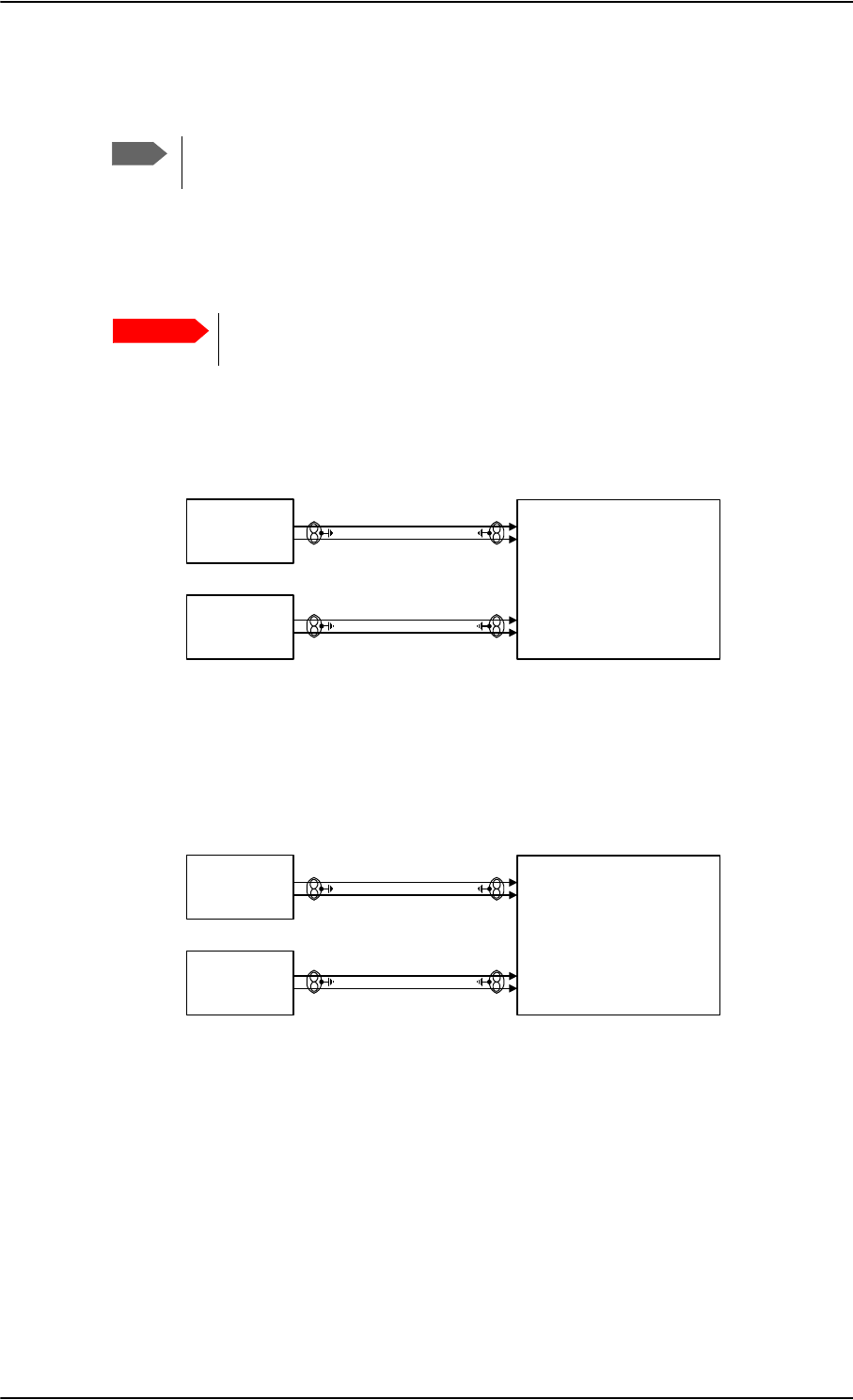
Electrical installation and wiring
5-32 Chapter 5: Installation 98-124743-F
5.3.5 Wiring ARINC 429 interfaces
Wiring an ARINC 429 source system
The SDU has two ARINC 429 input interfaces for 2 NAV sources. The SBU has two
ARINC 429 input interfaces for two navigational inputs.
For instructions how to install and set up the IRS or AHRS system see the
respective installation manual.
The following drawing shows the wiring of a navigational input. Requirements to the cables
are stated in the section Cable requirements, ARINC 429 on page 5-36.
Figure 5-11: Wiring AHRS/IRS to SDU
Figure 5-12: Wiring IRS to SBU
For more information on AHRS/IRS see About satcom antenna steering on page 5-6.
Note
The source for navigational data over ARINC 429 can be either an IRS, AHRS or
another navigational input compatible with the requirements in this section.
Important
$+56,56
+6/6$5,1&5;
$+56,56
+6/6$5,1&5;
77$
6'8
%3
%3
%3
%3
,56
+6/6$5,1&5;
,56 +6/6$5,1&5;
77$
6%8
%3
%3
%3
%3
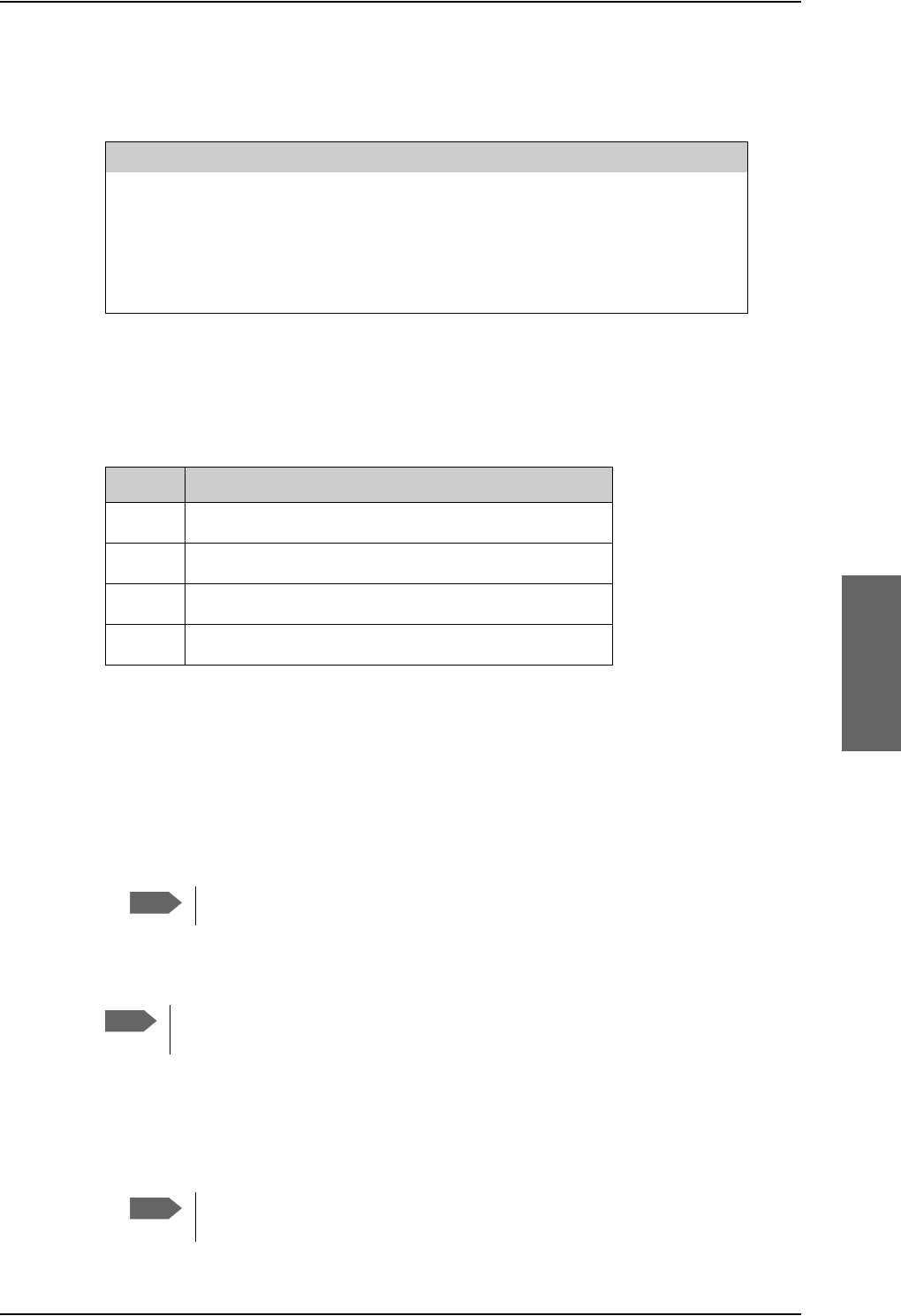
Electrical installation and wiring
98-124743-F Chapter 5: Installation 5-33
Pins for AHRS/IRS for SDU
The following list shows the pins used for AHRS or IRS:
Pins for input from ARINC 429 sources for SBU
The pins for navigational input are located in the bottom plug of the SBU rear receptacle.
Description of the interface for navigational input
For SDU: When the system is configured with the Aero-SDU Configuration Program, the
Configuration Module will contain the information of:
• Which navigational input is selected: IRS or AHRS.
• Whether primary or secondary input or both are installed.
•ARINC 429 Speed (High or Low). The primary and secondary AHRS/IRS inputs can
individually be set to high or low speed, depending on your configuration.
For SBU: When the system is configured with the web interface, the CM contains the
information:
• Which navigational input is selected: IRS or GPS.
• Whether primary or secondary input or both are installed.
If primary and secondary ARINC 429 navigational input are both installed,
they must be of the same type (IRS, AHRS, NPI or GNSS).
SDU Pin Name/Description
BP26 Data from primary IRS 429 A /Data from primary AHRS 429 A
BP27 Data from primary IRS 429 B /Data from primary AHRS 429 B
BP28 Data from secondary IRS 429 A /Data from secondary AHRS 429 A
BP29 Data from secondary IRS 429 B /Data from secondary AHRS 429 B
Table 5-25: SDU pins for IRS and AHARS
SBU pin Name/description
BP5 Data from primary ARINC 429 navigational input A
BP8 Data from primary ARINC 429 navigational input B
BP7 Data from secondary ARINC 429 navigational input A
BP13 Data from secondary ARINC 429 navigational input B
Table 5-26: SBU pins for input from a navigational ARINC 429 source
Note
If #1 and #2 are both installed, they must be of the same type (IRS or AHRS).
Note
AHRS can only be used with the HGA 7000 antenna, which contains a built-in GPS
antenna.
Note

Electrical installation and wiring
5-34 Chapter 5: Installation 98-124743-F
•ARINC 429 Speed (High or Low). The primary and secondary navigational inputs can
individually be set to high or low speed, depending on your configuration.
ARINC data format for IRS
The required ARINC data format for IRS is listed in the following table:
ARINC data format for AHRS
The required ARINC data format for AHRS is listed in the following table:
Label (octal) Name Minimum Update rate
150 UTC Time (optional)a1 Hz
260 UTC Date (optional)a1 Hz
310 Latitude 1 Hz
311 Longitude 1 Hz
312 Ground speed 1 Hz
313 Track angle True 1 Hz
314 True heading 10 Hz
324 Pitch angle 10 Hz
325 Roll angle 10 Hz
361 Altitude Inertial (optional)a
a. The labels marked optional do not have an effect on the operation
of the AVIATOR 700 system, but may increase precision in the
antenna pointing and time management.
1 Hz
Table 5-27: ARINC data format for IRS
Label (octal) Name Minimum update rate
320 Magnetic heading 10 Hz
324 Pitch angle 10 Hz
325 Roll angle 10 Hz
336 Inertial pitch rate (optional)a
a. The labels marked optional do not have an effect on the operation
of the AVIATOR 700 system, but may increase precision in the
antenna pointing.
10 Hz
337 Inertial roll rate (optional)a10 Hz
Table 5-28: ARINC data format for AHRS
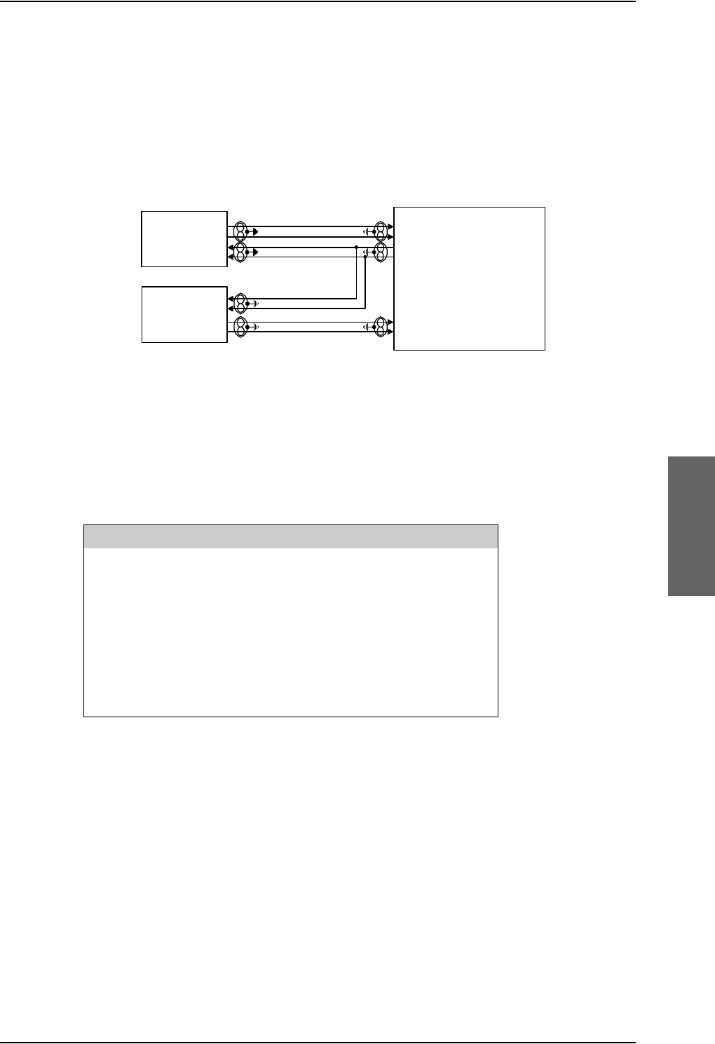
Electrical installation and wiring
98-124743-F Chapter 5: Installation 5-35
Wiring ACARS/AFIS/CMU
The SDU has ARINC 429 interfaces for 2 high or low speed (HS/LS) ACARS/AFIS/CMU
including one output port and 2 input ports.
The following drawing shows the wiring of ACARS/AFIS/CMU. Requirements to the cables
are stated in the section Cable requirements, ARINC 429 on page 5-36.
Pins for ACARS/AFIS/CMU
The following list shows the pins used for an Airborne Communications Addressing and
Reporting System (ACARS), Airborne Flight Information System (AFIS) or a
Communications Management Unit (CMU):
The data speed can be configured to high or low (HS/LS), defined by the Configuration
Module.
Wiring MCDU
The SDU has interfaces prepared for two high or low speed ARINC 429 interfaces for
communication with MCDU #1 and MCDU #2. One common output and two inputs.
The following drawing shows the wiring of MCDU. Requirements to the cables are stated in
the section Cable requirements, ARINC 429 on page 5-36.
Figure 5-13: Wiring ACARS/AFIS/CMU
$&$56&08
+6/6$5,1&7;
+6/6$5,1&5;
$&$56&08
+6/6$5,1&5;
77$
6'8
%3
%3
%3
%3
%3
%3
SDU Pin Name/Description
BP40 Data bus from ACARS/AFIS/CMU #1 429 A
BP41 Data bus from ACARS/AFIS/CMU #1 429 B
BP42 Data bus to ACARS/AFIS/CMU #1 & #2 429 A
BP43 Data bus to ACARS/AFIS/CMU #1 & #2 429 B
BP44 Data bus from ACARS/AFIS/CMU #2 429 A
BP45 Data bus from ACARS/AFIS/CMU #2 429 B
Table 5-29: SDU pins for ACARS/AFIS/CMU
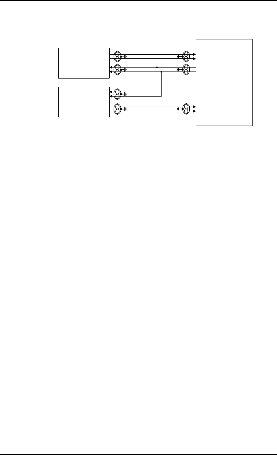
Electrical installation and wiring
5-36 Chapter 5: Installation 98-124743-F
The Configuration Module contains information if the MCDU is installed, and which data
rate is used (high or low).
Cable requirements, ARINC 429
The cables for the ARINC 429 interfaces must be twisted and shielded. They must conform
to the standards for aeronautical use.
For recommended cable types, see Recommended cables for ARINC 429 on page 5-85.
Figure 5-14: Wiring MCDU
77$
6'8
0&'8
+6/6$5,1&5;
0&'8
+6/6$5,1&5; %3
%3
%3
%3
%3
%3
+6/6$5,1&7;
Electrical installation and wiring
98-124743-F Chapter 5: Installation 5-37
5.3.6 Wiring GPS interface
Wiring the GPS antenna
The following figure shows the wiring of the GPS interface when using a power splitter. You
can use the power splitter shown in TT-5038A-003 Rx Power Splitter on page 3-8.
Pins for input from the GPS antenna
5.3.7 Wiring ICAO address
Strapped ICAO address
A unique aircraft identification code (ICAO address) must be assigned at installation. The
national authority of aeronautical identification coordinates assignment of the code.
The ICAO address must be entered in the Configuration Module, using the Aero-SDU
Configuration Program.
Figure 5-15: Wiring GPS Interface with Power Splitter
'&%/2&.
*36
$QWHQQD
3RZHU6SOLWWHU
G%#*+=
*36DQWHQQD
/DEHOWH[W'/1$
6%8
/DEHOWH[W6'8
77$
6%8
%3$
*36LQ
77$
6'8
73$
*36LQ
/DEHOWH[W+68
7KHODEHOWH[WRQWKH3RZHU
6SOLWWHULVPLVOHDGLQJ
SBU pin Name/description
BP A4 GPS antenna input (coax), modem, DC out
Table 5-30: SBU pins for input from GPS antenna
SDU pin Name/description
TP A4 GPS/Antenna modem interface (coax)
Table 5-31: SDU pins for input from GPS antenna
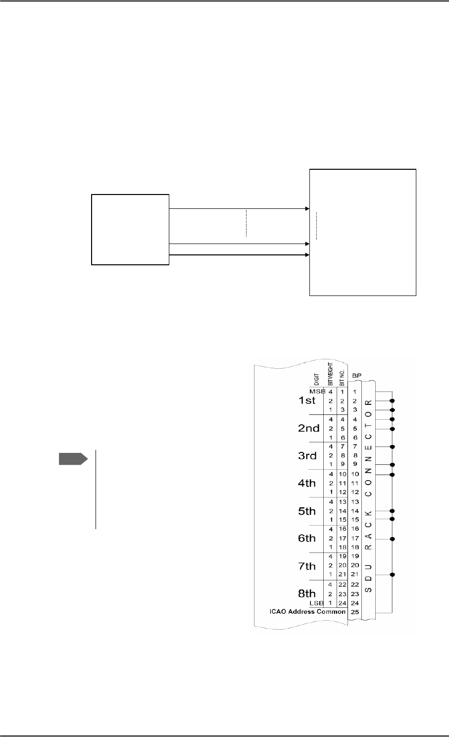
Electrical installation and wiring
5-38 Chapter 5: Installation 98-124743-F
The SDU obtains the ICAO address from the 24 bit discrete address (must be hardware
strapped using the 24 discrete inputs on the SDU).
The strapped ICAO address is compared to the ICAO address entered in the Configuration
Module of the SDU. If they do not match, the AVIATOR 700 system suspends all RF
communication.
Wiring ICAO address
The following drawing shows the wiring of the 24 bit discrete ICAO address.
Figure 5-17: Example of wiring the fictional
ICAO address 01234567
0
0
0
0
0
1
0
1
0
0
1
1
1
0
0
1
0
1
1
1
0
1
1
1
0
1
}
}
}
BIN DEC
2
}
}
}
}
}
3
4
5
6
7
Wiring 24 bit discrete ICAO address
The SDU has 24 discrete inputs used to
encode the 24-bit ICAO address, in which
the SDU is installed.
Each ICAO address consists of eight
digits, and each digit value is determined
by strapping 3 bits (octal).
Do as follows to strap the ICAO address:
1. Leave pins assigned to the binary
“one” state open (internal pull up).
Binary “one” (open circuit) is
100 k
2. Strap pins assigned to the binary
“zero” state to BP25 (ICAO Address
Common) on the airframe side of the
connector.
Figure 5-16: Wiring ICAO
77$
6'8
ELW,&$2
DGGUHVV
GLVFUHWH
,&$2$''5(66%,706%
,&$2$''5(66%,7/6%
,&$2$''5(66&20021
%3
%3
%3
Note
The Aero-SDU Configuration
Program shows which pins to
connect if you type in the wanted
ICAO address in the Config
Module field in the Identification
window.

Electrical installation and wiring
98-124743-F Chapter 5: Installation 5-39
Binary “zero” (strapped to BP25) is 10 .
3. Enter the ICAO address in the Aero-SDU Configuration Program.
If the aircraft uses a US N-type registration number, the Aero-SDU Configuration
Program can calculate the ICAO address from this number. Use the US N-Type
Calculator button in the Identification window of the Aero-SDU Configuration
Program.
When the system is powered, the SDU reads the strapped ICAO address from the SDU rack
connector and compares it to the ICAO address entered in the Configuration Module. If the
SDU does not detect or recognize the strapped ICAO address, the AVIATOR 700 system
suspends all RF communication until the error is corrected.
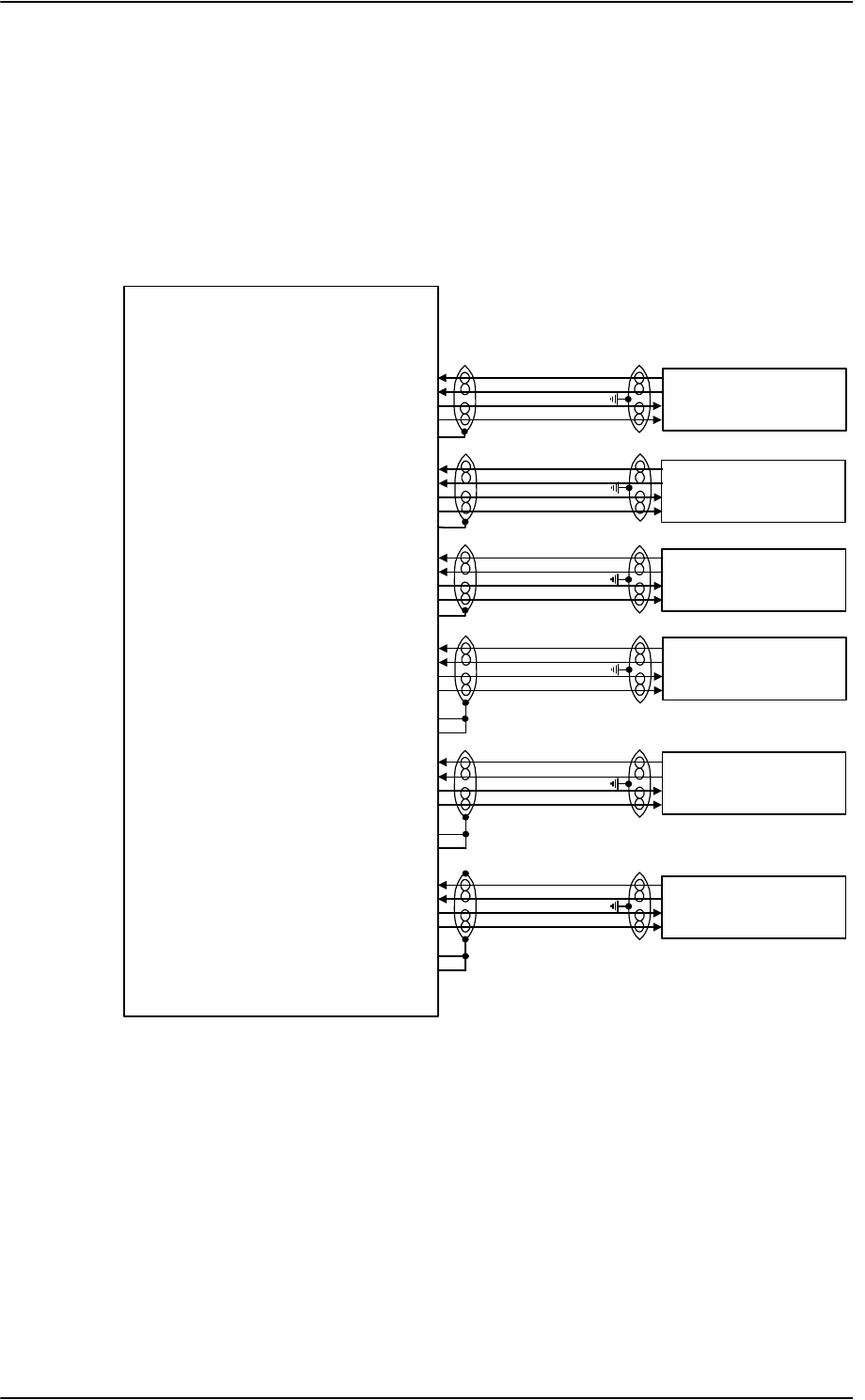
Electrical installation and wiring
5-40 Chapter 5: Installation 98-124743-F
5.3.8 Wiring Ethernet at the SBU
Overview
The SBU has six 10/100BaseT Ethernet interfaces, plus the interface on the front of the
SBU described in Wiring the Maintenance interfaces and Reset on page 5-76.
The following drawing shows the wiring of the rear SBU Ethernet interfaces.
The RJ45 Ethernet interfaces match a standard straight network cable. You can freely select
which of the Ethernet connections you want to use.
The supported cable length is up to 100 meters (328 feet).
Figure 5-18: Wiring Ethernet
77$
6%8
7[%DVH7(WKHUQHWLQSXW%3$
7[%DVH7(WKHUQHWLQSXW%3$
5[%DVH7(WKHUQHWRXWSXW%3$
5[%DVH7(WKHUQHWRXWSXW%3$
%3$VKLHOG
7[%DVH7(WKHUQHWLQSXW%3$
7[%DVH7(WKHUQHWLQSXW%3$
5[%DVH7(WKHUQHWRXWSXW%3$
5[%DVH7(WKHUQHWRXWSXW%3$
%3$VKLHOG
7[%DVH7(WKHUQHWLQSXW%3$
7[%DVH7(WKHUQHWLQSXW%3$
5[%DVH7(WKHUQHWRXWSXW%3$
5[%DVH7(WKHUQHWRXWSXW%3$
%3$VKLHOG
7[%DVH7(WKHUQHWLQSXW%3
7[%DVH7(WKHUQHWLQSXW%3
5[%DVH7(WKHUQHWRXWSXW%3
5[%DVH7(WKHUQHWRXWSXW%3
7[%DVH7(WKHUQHWLQSXW%3
7[%DVH7(WKHUQHWLQSXW%3
5[%DVH7(WKHUQHWRXWSXW%3
5[%DVH7(WKHUQHWRXWSXW%3
7[%DVH7(WKHUQHWLQSXW%3
7[%DVH7(WKHUQHWLQSXW%3
5[%DVH7(WKHUQHWRXWSXW%3
5[%DVH7(WKHUQHWRXWSXW%3
5-
)HPDOH&RQQHFWRU
5-
)HPDOH&RQQHFWRU
5-
)HPDOH&RQQHFWRU
5-
)HPDOH&RQQHFWRU
5-
)HPDOH&RQQHFWRU
5-
)HPDOH&RQQHFWRU
&RPPRQ6LJQDO*1'%3
&RPPRQ6LJQDO*1'%3
&RPPRQ6LJQDO*1'%3
&RPPRQ6LJQDO*1'%3
&RPPRQ6LJQDO*1'%3
&RPPRQ6LJQDO*1'%3

Electrical installation and wiring
98-124743-F Chapter 5: Installation 5-41
Pins for 10/100BaseT Ethernet
The following list shows the pins used for the Ethernet interface.
SBU pin Name Description RJ45 pin (F) Name
BP A1.1 Tx+ 10/100BaseT Ethernet #1 Input 1 TxD+
BP A1.2 Rx+ 10/100BaseT Ethernet #1 Output 3 RxD+
BP A1.3 Tx- 10/100BaseT Ethernet #1 Input 2 TxD-
BP A1.4 Rx- 10/100BaseT Ethernet #1 Output 6 RxD-
BP A2.1 Tx+ 10/100BaseT Ethernet #2 Input 1 TxD+
BP A2.2 Rx+ 10/100BaseT Ethernet #2 Output 3 RxD+
BP A2.3 Tx- 10/100BaseT Ethernet #2 Input 2 TxD-
BP A2.4 Rx- 10/100BaseT Ethernet #2 Output 6 RxD-
BP A3.1 Tx+ 10/100BaseT Ethernet #3 Input 1 TxD+
BP A3.2 Rx+ 10/100BaseT Ethernet #3 Output 3 RxD+
BP A3.3 Tx- 10/100BaseT Ethernet #3 Input 2 TxD-
BP A3.4 Rx- 10/100BaseT Ethernet #3 Output 6 RxD-
BP6 Rx- 10/100BaseT Ethernet #4 Output 6 RxD-
BP10 Tx+ 10/100BaseT Ethernet #4 Input 1 TxD+
BP11 Tx- 10/100BaseT Ethernet #4 Input 2 TxD-
BP15 Common Signal GND for Ethernet GND Shield
BP16 Rx+ 10/100BaseT Ethernet #4 Output 3 RxD+
BP17 Common Signal GND for Ethernet GND Shield
BP19 Rx- 10/100BaseT Ethernet #5 Output 6 RxD-
BP20 Tx- 10/100BaseT Ethernet #5 Input 2 TxD-
BP21 Common Signal GND for Ethernet GND Shield
BP22 Common Signal GND for Ethernet GND Shield
BP23 Rx- 10/100BaseT Ethernet #6 Output 6 RxD-
BP24 Tx- 10/100BaseT Ethernet #6 Input 2 TxD-
BP25 Tx+ 10/100BaseT Ethernet #5 Input 1 TxD+
Table 5-32: SBU Pins for 10/100BaseT Ethernet
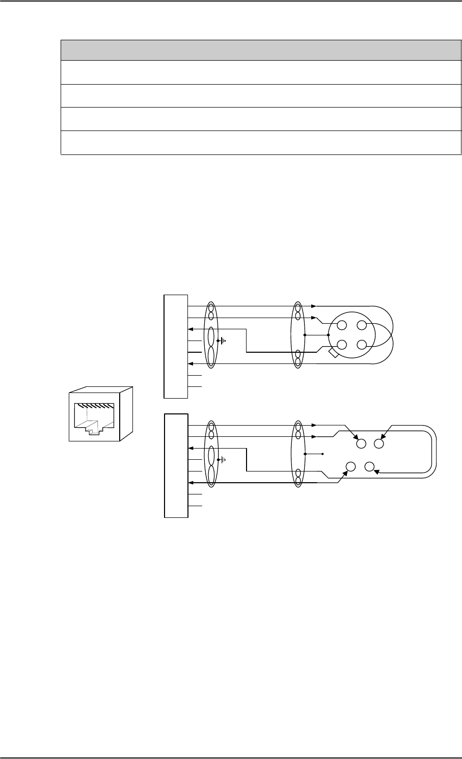
Electrical installation and wiring
5-42 Chapter 5: Installation 98-124743-F
Wiring of RJ45 connector to Quadrax connector
The physical layer conforms to IEEE standard 802.3 [1], Chapter 14: “Twisted Pair medium
attachment unit”, except for the connector type. To be compliant with [1], use an RJ45
female connector for the user interface. The below drawing shows the corresponding RJ45
connection. The SBU is configured as Data communication Equipment (DCE), i.e. TX +/- are
input and RX +/- are outputs.
Figure 5-19: Ethernet pin configuration for SBU
Common Signal GND (BP15, BP17, BP21, BP22 and BP27)
Common Signal GND is used to connect the shield of the Ethernet cables for Ethernet #4,
#5 and #6 on the SBU. The shield for each cable is connected according to Figure 5-
18: Wiring Ethernet. The shield of the Ethernet cables for Ethernet #1, #2 and #3 is
connected to the shield of the Quadrax connectors.
BP26 Rx+ 10/100BaseT Ethernet #5 Output 3 RxD+
BP27 Common Signal GND for Ethernet GND Shield
BP28 Tx+ 10/100BaseT Ethernet #6 Input 1 TxD+
BP29 Rx+ 10/100BaseT Ethernet #6 Output 3 RxD+
SBU pin Name Description RJ45 pin (F) Name
Table 5-32: SBU Pins for 10/100BaseT Ethernet (Continued)
6%8SLQ
73$$$
6KLHOG
7[' 7;LQSXW
QF
7[' 7; LQSXW
5['
5;RXWSXW
QF
5[' 5; RXWSXW
QF
QF 2KP TXDGUD[WZLVWHG
DQGVKLHOGHGSDLUV
7[' 7;LQSXW
QF
7[' 7; LQSXW
5['
5;RXWSXW
QF
5[' 5; RXWSXW
QF
QF
DQGVKLHOGHGSDLUV
6%8SLQ
6%8'&(
%3 %3
%3
5-
IHPDOH
WR'7(
%3
%3
&DEOH
&DEOH
2KP TXDGUD[WZLVWHG
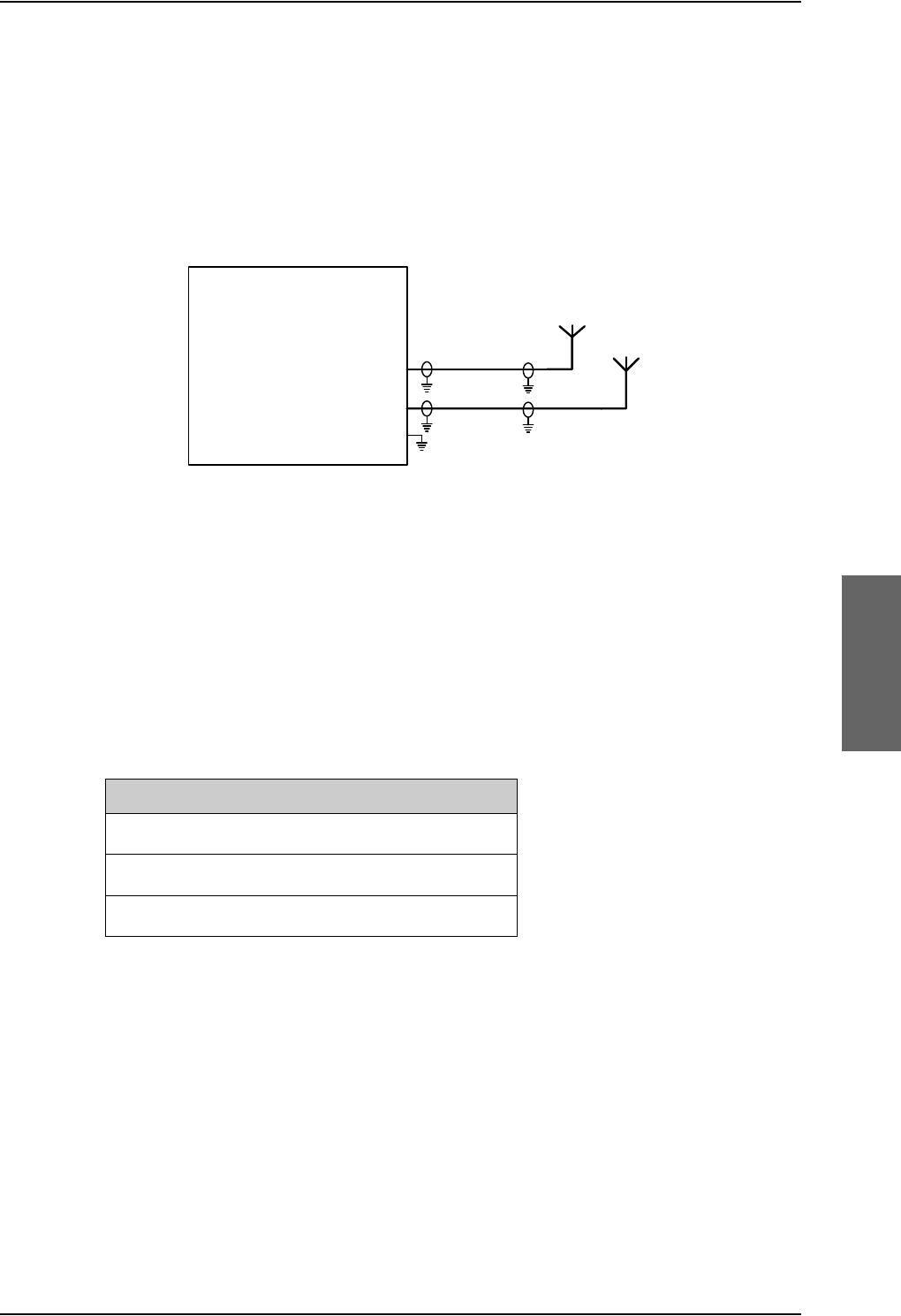
Electrical installation and wiring
98-124743-F Chapter 5: Installation 5-43
5.3.9 Wiring WLAN antenna interface
Before wiring the WLAN antenna interface make sure that your system has the Built-in
Wireless Option TT-5040A-003.
Overview
The following drawing shows the wiring of the SBU WLAN antenna interfaces.
WLAN low pass filter
The WLAN module in the SBU can in theory transmit in the 5 GHz (802.11a) frequency
range. This is inhibited permanently by the software in the SBU. If the aircraft cannot be
tested to be immune to 5 GHz signals, you can optionally insert a 2.4 GHz low pass filter
into the WLAN Coax to safeguard the aircraft against transmission in the 5 GHz frequency
range.
WLAN pins
The following list shows the pins used for the WLAN antenna interface on the SBU.
Description of WLAN interface
The WLAN interface on the SBU supports operation according to the IEEE 802.11b and
802.11g standards. The WLAN (2.4GHz) frequency band is divided into 14 channels.
Not all countries allow full use of all channels. Also, some countries do not allow operation
according to the 802.11g standard. Therefore the WLAN interface must be set up to the
right country code. For further information, see WLAN country codes on page E-1.
The maximum EIRP output level for WLAN 802.11b and 802.11g is 100 mW for indoors
use. To prevent the EIRP output power from exceeding this limit, the maximum antenna
gain must not exceed the cable loss between the antenna and the SBU.
Figure 5-20: Wiring WLAN antenna interfaces #1 and #2
77$
6%8
:/$1DQWHQQDFRD[73$
:/$1DQWHQQDFRD[73$
73
:/$1HQDEOH
:/$1DQWHQQDDQG
:
:
SBU pin Name/description
TPA2 WLAN antenna #1 (coax)
TPA4 WLAN antenna #2 (coax)
TP5 WLAN Enable, Discrete Input (active low)
Table 5-33: SBU pins for WLAN antenna #1 and #2

Electrical installation and wiring
5-44 Chapter 5: Installation 98-124743-F
Operating with a single WLAN antenna
If operating with a single WLAN antenna, it is recommended to use the WLAN pin TP A4.
Make sure to set up WLAN interface correctly — Antenna configuration: Main or Aux for
single antenna operation — see WLAN interface of the SBU (option) on page 6-31.
Table 5-34: WLAN antenna configuration
Antenna configuration SBU TP A2 SBU TP A4
Diversity (antenna #1 and #2) RX TX/RX
Main (antenna #2) –TX/RX
Aux (antenna #1) TX/RX –
RF cable requirements for WLAN
To achieve optimal performance for the WLAN system select a cable type with a minimal
cable loss when cabling the TT5040A-004 WLAN antenna. For a table with cable types and
cable losses see Recommended RF cables on page 5-84.
Cable Min. cable loss
@2.4 GHz
Max. cable loss
@2.4 GHz
From TP A2 to TT5040A-004 WLAN antenna
and TP A4 to TT5040A-004 WLAN antenna
0 dB 5 dB
Table 5-35: Cable requirements for WLAN
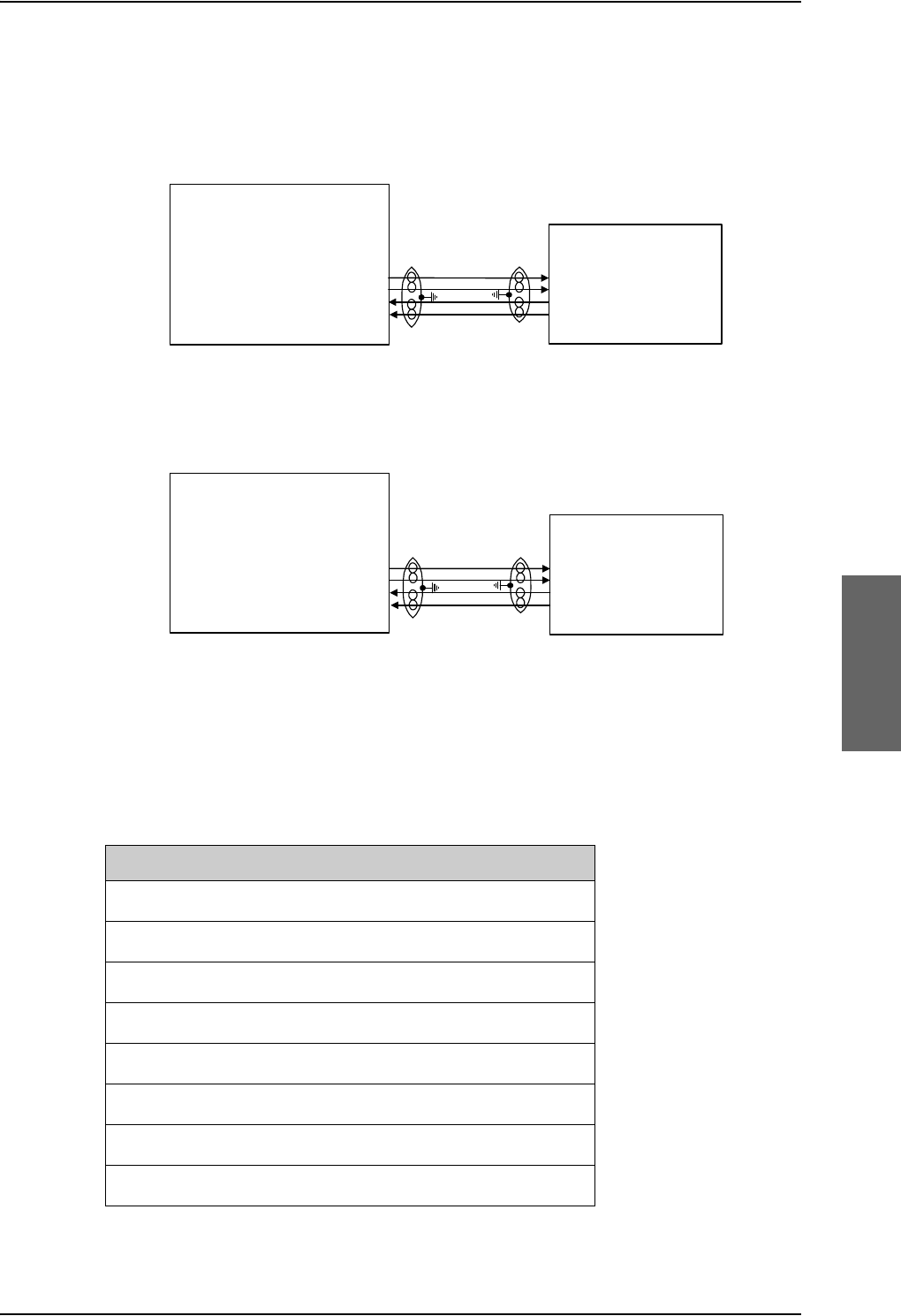
Electrical installation and wiring
98-124743-F Chapter 5: Installation 5-45
5.3.10 Wiring ISDN
Wiring drawing
Note that even though the AVIATOR 700 system supports connection of several ISDN
devices, the satellite channel only supports transmission on one ISDN channel.
Pins for ISDN
The following lists show the pins used for the ISDN interfaces on the SBU and the SDU.
Figure 5-21: Wiring ISDN
,6'1
7(
5-
)HPDOH&RQQHFWRU
,6'17[GRXWSXW73
,6'17[HRXWSXW73
,6'15[FLQSXW73
,6'15[ILQSXW73
77$
6%8
17
5[LQSXW
5[LQSXW
7[RXWSXW
7[RXWSXW
77$
6'8
17
,6'17[RXWSXWG%3
,6'17[RXWSXWH%3
,6'15[LQSXWF%3
,6'15[LQSXWI%3
,6'1
7(
5-
)HPDOH&RQQHFWRU
5[LQSXW
5[LQSXW
7[RXWSXW
7[RXWSXW
([WHUQDOSRZHUVXSSO\
UHTXLUHG
SBU pin Name/description
TP23 ISDN #1 Rx+ (c) input (NT)
TP24 ISDN #1 Tx+ (d) output (NT)
TP25 ISDN #1 Tx- (e) output (NT)
TP26 ISDN #1 Rx- (f) input (NT)
TP15 ISDN #2 Tx+ (c) output (TE), reserved for future use
TP16 ISDN #2 Rx+ (d) input (TE), reserved for future use
TP17 ISDN #2 Rx- (e) input (TE), reserved for future use
TP18 ISDN #2 Tx- (f) output (TE), reserved for future use
Table 5-36: SBU pins for ISDN
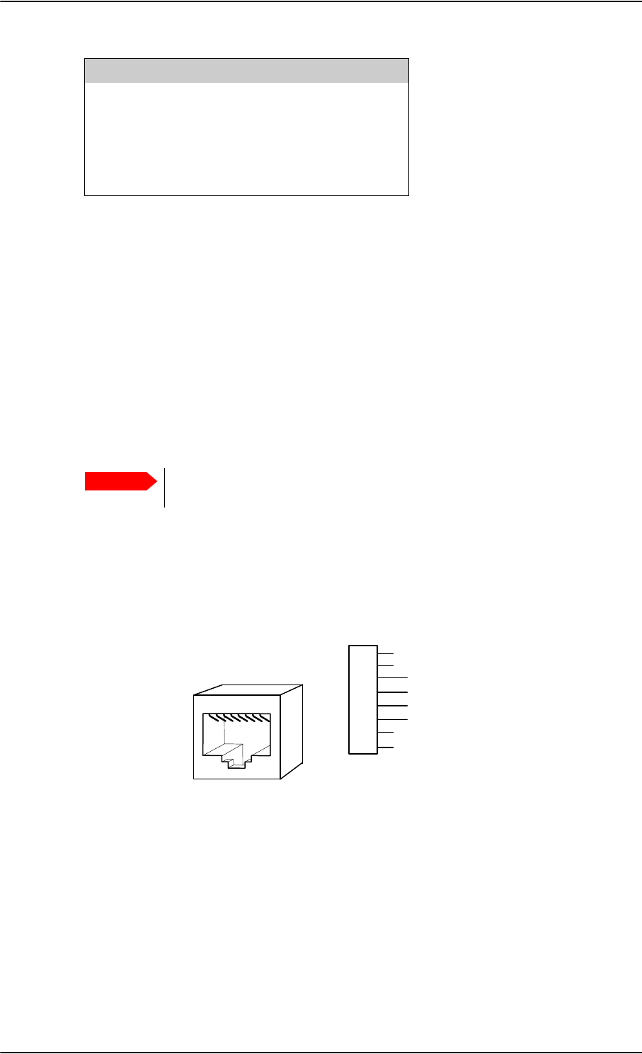
Electrical installation and wiring
5-46 Chapter 5: Installation 98-124743-F
Description of SBU and SDU ISDN interface
The SBU and SDU have one ISDN interface each. The ISDN of the SDU uses the Swift64
service (I3), the ISDN of the SBU uses the SwiftBroadband service (I4). Each interface has
its own ISDN controller and front end. The Euro ISDN S-bus interface is configured as the
network side of the NT1 interface i.e. Rx is an input and Tx is an output Please note that this
configuration of input and output differs from the configuration of the 10BaseT Ethernet,
RS-422 and RS-232 PC interface input/output (valid for SBU and SDU).
The ISDN interface can address up to 8 ISDN devices. The SBU ISDN interface supports
56/64kbps data rate and G4 Fax on the SwiftBroadband connection. You can also use the
SBU ISDN interface to make an AMBE2 or 3.1 kHz audio call. The SDU interface supports
56/64kbps data rate and G4 Fax on Swift64.
There is no DC power on the ISDN interface of the SBU. All ISDN devices
connected to the SBU must be powered externally.
To be compliant with ISO8877 [2] and the ISDN connector specification defined by ITU
I.420 [6], an RJ45 Female Connector must be connected to the four-wire ISDN lines from
the SBU.
The SBU includes an internal 100 termination resistor to support cable lengths up to
100 meters (109 yards). Make sure the other end of the cable is terminated properly.
Cable requirements, ISDN
• Cable for the ISDN interface: 100 4-wire shielded cable.
• The conductors must be twisted in pairs.
• Supported cable lengths: up to 100 meters (328 feet).
SDU pin Name/Description
BP67 ISDN Tx+ output (d)
BP68 ISDN Tx- output (e)
BP66 ISDN Rx+ input (c)
BP69 ISDN Rx- input (f)
Table 5-37: SDU pins for ISDN
Important
Figure 5-22: ISDN RJ45 connector
,6'15[,QSXWF
,6'17[2XWSXWG
,6'17[2XWSXWH
,6'15[,QSXWI
QRWFRQQHFWHG
5-IHPDOHFRQQHFWRU
QRWFRQQHFWHG
QRWFRQQHFWHG
QRWFRQQHFWHG
5-
IHPDOH

Electrical installation and wiring
98-124743-F Chapter 5: Installation 5-47
5.3.11 Wiring telephone systems
Built-in Private Branch Exchange (PBX)
The AVIATOR 700 system has two built-in PBX systems: one in the SDU and one in the SBU.
• The PBX of the SDU controls four 4-wire audio interfaces, two 2-wire POTS interfaces
and one ISDN interface.
• The built-in PBX of the SBU controls the 2-wire POTS interfaces #1 and #2 and one
ISDN interface.
The built-in PBX of the SBU can also route VoIP calls that are terminated in the SIP server of
the SBU.
Without the Multi-voice option the AVIATOR 700 system supports one external call at a
time going through the SBU and two external calls going through the SDU.
VoIP calls and SIP telephony
You can use phones with a SIP client and the WLAN interface to make calls. These calls are
terminated in the SIP server of the SBU and routed through the built-in PBX on the Swift
Broadband channel. For a detailed description how to set up your phone see SIP setup for
Wifi-enabled phones on page H-1.
4-wire audio
The 4-wire interfaces can be connected and configured to the 4-wire systems listed below:
• TT-5620A/TT-5622A Handset/Cradle system
• Up to two MagnaStar AIU (Analog Interface Units)
• One Iridium ICS telephone system
• Up to three 2.4 GHz Cordless handset base stations with WH-10 Satcom interface
• Up to three WH-10 handsets
• Up to two Cockpit Voice Interfaces
The four 4-wire handset interfaces are numbered handset interface #1 to #4.
• Handset interface #1 and #2 may interface to all systems mentioned above.
• Handset interface #3 may interface to all systems mentioned above except Cockpit
Voice.
• Handset interface #4 may only interface to TT-5620A/TT-5622A Handset/Cradle
system.
The TT-5620A/TT-5622A 4-wire Handset/Cradle system is also used for configuration of
the handsets, phone book etc., and as a BITE and Satcom Status display. In order to use
these features, the SDU must be connected to at least one TT-5620A/TT-5622A
Handset/Cradle system (typically handset #4).
Do not use the 4-wire handset for cabin installation! Some of the functions of
the 4-wire handset are for cockpit use only.
Important

Electrical installation and wiring
5-48 Chapter 5: Installation 98-124743-F
2-wire POTS interface #1 and #2
The 2-wire interfaces may be connected and configured to the 2-wire systems listed below:
• TT-5621B 2-Wire Handset / TT-5622B 2-Wire Cradle
• ICG DECT Cordless Handset with POTS interface
•Sigma
7 phone with POTS interface
• Fax or Modem data with POTS interface
• Headset interface box PTA-12 Airborne telephone adapter
• Secure devices with POTS interface (STU/FNBDT)
The maximum number of telephones on each 2-wire POTS interface is:
Two TT-5621B 2-Wire Handset / TT-5622B 2-Wire Cradle or two Sigma7 phones.
The AVIATOR 700 system supports 3 external call at a time: 2 calls on H+, 1 call on
SwiftBroadband.
ISDN interface
The ISDN interface on the SBU and SDU may be used with an ISDN phone or fax machine
and/or an ISDN data modem. A maximum of 8 ISDN units (ISDN phones, ISDN fax or ISDN
data modem) may be connected to the ISDN interface, but only one unit may be active at a
time. Secure device is supported with ISDN interface (STE).
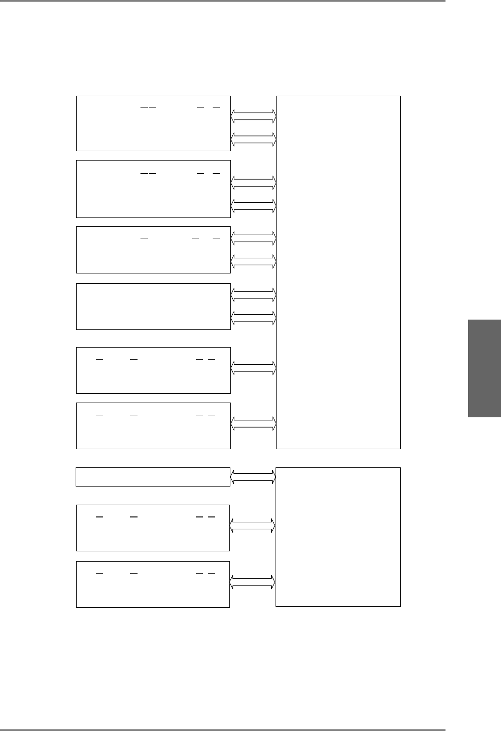
Electrical installation and wiring
98-124743-F Chapter 5: Installation 5-49
Configuration of wired handset interfaces
The following drawing shows the possible combinations of devices connected to the
handset interfaces.
Figure 5-23: Handset interfaces, possible combinations of connected devices.
77$6%8
3ULYDWH%UDQFK([FKDQJH3%;
>@0D[LPXPWZR0DJQD6WDU$,8VPD\EHLQVWDOOHG7KHSUHIHUUHG
LQVWDOODWLRQRI$,8LVWRWKHIRXUZLUH+DQGVHWLQWHUIDFHEXW$,8
PD\DOWHUQDWLYHO\EHFRQQHFWHGWRWKHIRXUZLUH+DQGVHWLQWHUIDFH
LQVWHDG
77$6'8
3ULYDWH%UDQFK([FKDQJH3%;
ZLUHDXGLR
&RQWUROVLJQDOV
77$77$+DQGVHW6\VWHPRU
0DJQDVWDU
>@
$,8RU
,ULGLXP,&6
>@
RU
*+]&RUGOHVV3KRQH:+RU
&RFNSLW9RLFH$06
)RXUZLUH+DQGVHWLQWHUIDFH
ZLUHDXGLR
&RQWUROVLJQDOV
77$77$+DQGVHW6\VWHPRU
0DJQDVWDU
>@
$,8RU
,ULGLXP,&6
>@
RU
*+]&RUGOHVV3KRQH:+RU
&RFNSLW9RLFH$06
)RXUZLUH+DQGVHWLQWHUIDFH
ZLUHDXGLR
&RQWUROVLJQDOV
77$77$+DQGVHW6\VWHPRU
$OWHUQDWLYH0DJQDVWDU
>@
$,8RU
,ULGLXP,&6
>@
RU
*+]&RUGOHVV3KRQH:+
)RXUZLUH+DQGVHWLQWHUIDFH
ZLUHDXGLR
&RQWUROVLJQDOV
77$77$+DQGVHW6\VWHP
)RXUZLUH+DQGVHWLQWHUIDFH
ZLUH3276
77%77%FUDGOHKDQGVHWRU
*+]&RUGOHVV3KRQH3276RU
6LJPD
3KRQHRU
)$;RU0RGHP
7ZRZLUH+DQGVHWLQWHUIDFH
ZLUH3276
77%77%FUDGOHKDQGVHWRU
*+]&RUGOHVV3KRQH3276RU
6LJPD
3KRQHRU
)$;RU0RGHP
7ZRZLUH+DQGVHWLQWHUIDFH
,6'1
,6'13KRQHV,6'10RGHP
,6'1LQWHUIDFH
ZLUH3276
77%77%FUDGOHKDQGVHWRU
*+]&RUGOHVV3KRQH3276RU
6LJPD
3KRQHRU
)$;RU0RGHP
7ZRZLUH+DQGVHWLQWHUIDFH
ZLUH3276
77%77%FUDGOHKDQGVHWRU
*+]&RUGOHVV3KRQH3276RU
6LJPD
3KRQHRU
)$;RU0RGHP
7ZRZLUH+DQGVHWLQWHUIDFH
>@ 7ZR KDQGVHW LQWHUIDFHV IURP WKH ,&6 V\VWHP FDQ EH FRQQHFWHG WR
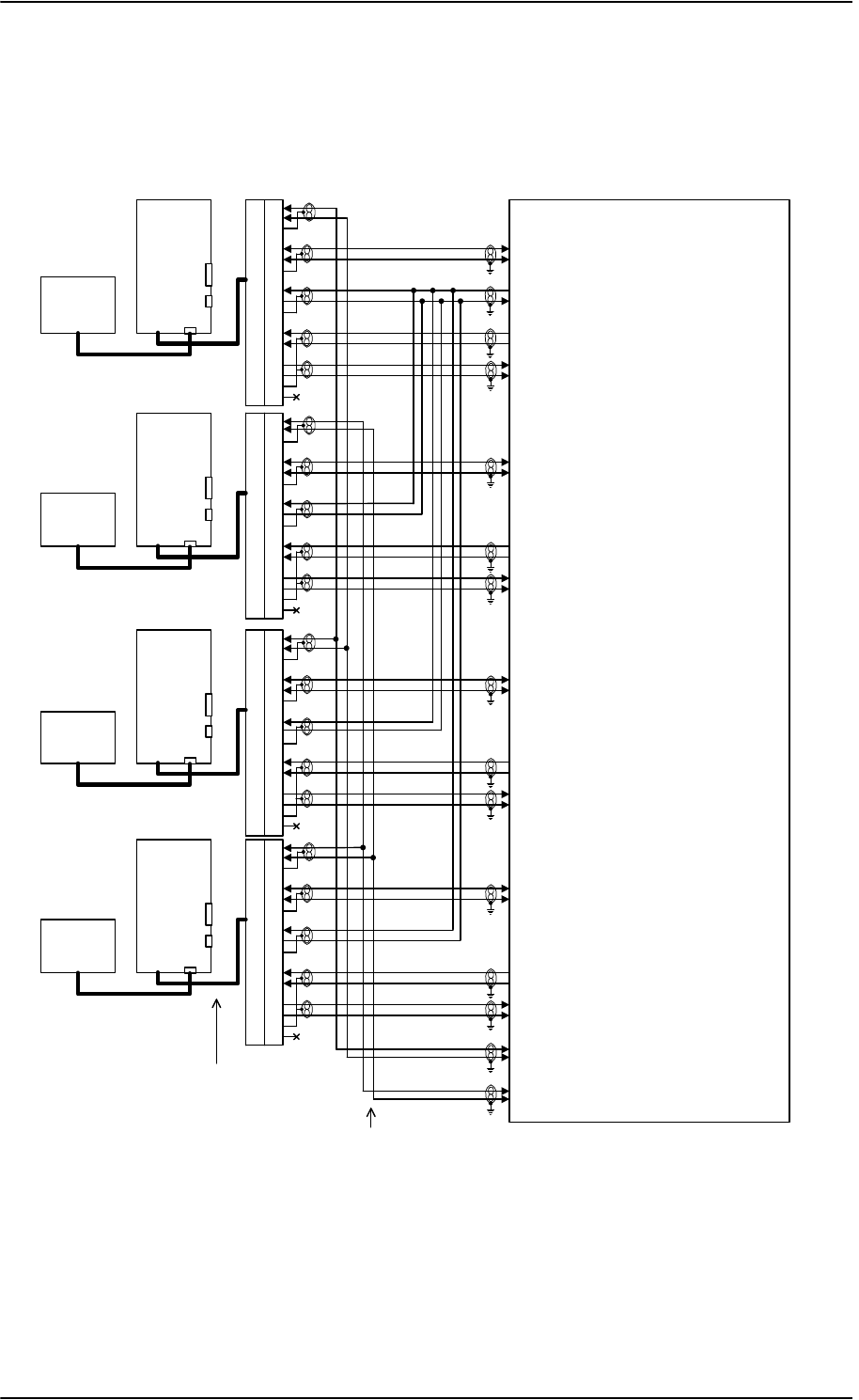
Electrical installation and wiring
5-50 Chapter 5: Installation 98-124743-F
Wiring 4-Wire Handsets
The following drawing shows the wiring of the TT-5622A/TT-5620A 4-Wire Handsets.
Figure 5-24: Wiring T&T 4-Wire Handset systems
77$
6'8
73
73
1&
%3$
%3%
73+L
73/R
73+L
73/R
1&
%3$
%3%
73+L
73/R
73+L
73/R
1&
%3$
%3%
73+L
73/R
73+L
73/R
%3$
%3%
73+L
73/R
73+L
73/R
'%)'%0
77$
&5$'/(
77$
+$1'6(7
77$
&5$'/(
77$
+$1'6(7
77$
&5$'/(
77$
+$1'6(7
$XGLR,2
77$
&5$'/(
77$
+$1'6(7
7ZR:LUH
ID[PRGHP
$XGLR,2
7ZR:LUH
ID[PRGHP
$XGLR,2
7ZR:LUH
ID[PRGHP
$XGLR,2
7ZR:LUHID[
PRGHP
1&
:LUH+DQGVHW56'DWD
&KDVVLV*URXQGDQG+DQGVHW3RZHU5HWXUQ
9'&P$+DQGVHW6XSSO\
+DQGVHW$XGLR2XW&RFNSLW9RLFH$XGLR2XW
+DQGVHW$XGLR,Q&RFNSLW9RLFH$XGLR,Q
:LUH+DQGVHW56'DWD
+DQGVHW$XGLR2XW&RFNSLW9RLFH$XGLR2XW
+DQGVHW$XGLR,Q&RFNSLW9RLFH$XGLR,Q
:LUH+DQGVHW56'DWD
+DQGVHW$XGLR2XW
+DQGVHW$XGLR,Q
73
73
7LS
5LQJ +DQGVHW:LUH9RLFH)D[0RGHP
73
73
7LS
5LQJ +DQGVHW:LUH9RLFH)D[0RGHP
+DQGVHW$XGLR2XW
+DQGVHW$XGLR,Q
:LUH+DQGVHW56'DWD
5-
5-
5-
5-
3LJWDLO
3LJWDLO
3LJWDLO
3LJWDLO
'%)
'%)
'%)
'%)
1RWH3LJWDLOZLWK6XE'FRQQHFWRULVPRXQWHGRQHDFKFUDGOH
:LULQJRI7LSDQG5LQJ6'87373DQG73LVRSWLRQDORQWKH:LUHLQWHUIDFHV

Electrical installation and wiring
98-124743-F Chapter 5: Installation 5-51
SDU pins for 4-wire interfaces
Pin no. Name/Description
TP10 Handset #1 Audio In Hi / Cockpit Voice Audio #1 In Hi
TP11 Handset #1 Audio In Lo / Cockpit Voice Audio #1 In Lo
TP12 Handset #1 Audio Out Hi / Cockpit Voice Audio #1 Out Hi
TP13 Handset #1 Audio Out Lo / Cockpit Voice Audio #1 Out Lo
BP94 Handset #1 RS-485 Data A
BP95 Handset #1 RS-485 Data B
TP15 Handset #2 Audio In Hi / Cockpit Voice Audio #2 In Hi
TP16 Handset #2 Audio In Lo / Cockpit Voice Audio #2 In Lo
TP17 Handset #2 Audio Out Hi / Cockpit Voice Audio #2 Out Hi
TP18 Handset #2 Audio Out Lo / Cockpit Voice Audio #2 Out Lo
BP96 Handset #2 RS-485 Data A
BP97 Handset #2 RS-485 Data B
TP21 Handset #3 Audio In Hi
TP22 Handset #3 Audio In Lo
TP23 Handset #3 Audio Out Hi
TP24 Handset #3 Audio Out Lo
BP98 Handset #3 RS-485 Data A
BP99 Handset #3 RS-485 Data B
TP26 Handset #4 Audio In Hi
TP27 Handset #4 Audio In Lo
TP28 Handset #4 Audio Out Hi
TP29 Handset #4 Audio Out Lo
BP100 Handset #4 RS-485 Data A
BP101 Handset #4 RS-485 Data B
TP4 +28 V DC / 600 mA Handset supply, remote On/Off control by TP5 (nON)
TP3 Handset Power Return
TP25 +12 V DC Spare Supply for test only - do not connect!
Table 5-38: SDU pins for 4-wire interface
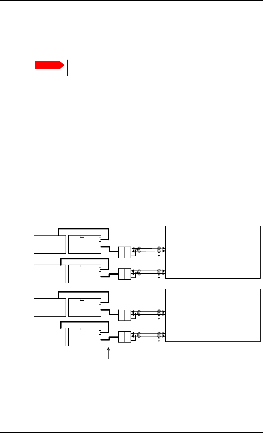
Electrical installation and wiring
5-52 Chapter 5: Installation 98-124743-F
Description of 4-wire interfaces
The SDU has four 4-wire analog interfaces for the TT-5620A/ TT-5622A Thrane & Thrane
aeronautical handset system on the rear connector. The handsets use an RS-485 data bus
for on/off hook signalling, display control, keyboard control, background light, etc.
AVIATOR 700D: For safety reasons do not install the 4-wire handset in the
cabin, see also Mounting considerations, SDU on page 5-5.
Three of the 4-wire interfaces, #1, #2 and #3, can alternatively be used for connection of
other supported phones (MagnaStar, WH-10 phones, Iridium ICS-200 telephone system,
FONE). For information on possible combinations, see Configuration of wired handset
interfaces on page 5-49. You must configure the handset interfaces must be configured in
the Aero-SDU Configuration Program.
For information on wiring of WH-10 phones, refer to Wiring WH-10 handsets on page 5-
54.
For information on wiring of ICS-200 telephone system, refer to Wiring ICS-200 telephone
system on page 5-57.
For information on wiring of 2.4GHz Cordless phones, refer to Wiring 2.4GHz Cordless (4-
wire) phone on page 5-60.
Wiring 2-Wire Handsets
The following drawing shows the wiring of the TT-5621B 2-Wire Handset / TT-5622B 2-
Wire Cradle.
Important
Figure 5-25: Wiring T&T 2-Wire Handset systems
77$
6'8
77%
:LUH&UDGOH
77%
:LUH&UDGOH
:LUHID[PRGHP
:LUHID[PRGHP
'%)'%0
'%0 '%)
77%
:LUH+DQGVHW
77%
:LUH+DQGVHW
73
73
7LS
5LQJ +DQGVHW:LUH9RLFH)D[0RGHP
73
73
7LS
5LQJ +DQGVHW:LUH9RLFH)D[0RGHP
5-
5-
3LJWDLO
3LJWDLO
1RWH3LJWDLOZLWK6XE'FRQQHFWRULVPRXQWHGRQHDFKFUDGOH
77$
6%8
77%
:LUH&UDGOH
77%
:LUH&UDGOH
:LUHID[PRGHP
:LUHID[PRGHP
'%)'%0
'%0 '%)
77%
:LUH+DQGVHW
77%
:LUH+DQGVHW
73
73
7LS
5LQJ +DQGVHW:LUH9RLFH)D[0RGHP
73
73
7LS
5LQJ +DQGVHW:LUH9RLFH)D[0RGHP
5-
5-
3LJWDLO
3LJWDLO

Electrical installation and wiring
98-124743-F Chapter 5: Installation 5-53
Pins for 2-wire interfaces
The below lists show the pins used for the 2-wire interfaces of the SDU and the SBU.
Table 5-39: SDU pins for 2-wire interface
TP6 2-Wire Voice/Fax/Modem #1 (Ring)
TP7 2-Wire Voice/Fax/Modem #2 (Ring)
TP8 2-Wire Voice/Fax/Modem #2(Tip)
TP19 2-Wire Voice/Fax/Modem #1 (Tip)
Table 5-40: SBU pins for 2-Wire interface
TP6 2-Wire Voice/Fax/Modem #1 (Ring)
TP7 2-Wire Voice/Fax/Modem #2 (Ring)
TP11 2-Wire Voice/Fax/Modem #1 (Tip)
TP12 2-Wire Voice/Fax/Modem #2 (Tip)
Description of 2-wire interfaces
The SDU and the SBU each have two 2-wire Voice/Fax/Modem POTS interfaces connected
to the PBX. The interfaces comply with 2-wire 600 standard US DTMF telephones. The 2-
wire interfaces are not galvanically isolated from the aircraft frame. Galvanic isolation is
required at the external 2-wire terminal.
Two TT-5621B 2-Wire Handset phones can be connected in parallel on each interface.
These interfaces are used for the TT-5621B/ TT-5622B Thrane & Thrane aeronautical
handset system, but may also be used for e.g. the Sigma7, ICG DECT Cordless Handset
phones, fax, modem or secure devices and PTA-12.
For information on wiring of Sigma7 phones, see Wiring Sigma7 (2-wire) handsets on
page 5-63. For information on wiring of ICG DECT Cordless Handset phones, see Wiring
ICG DECT Cordless Handset (2-wire) phone on page 5-64.
Supported cable length: 100 meters (328 feet)
SDU pin Name/Description
SBU pin Name/Description
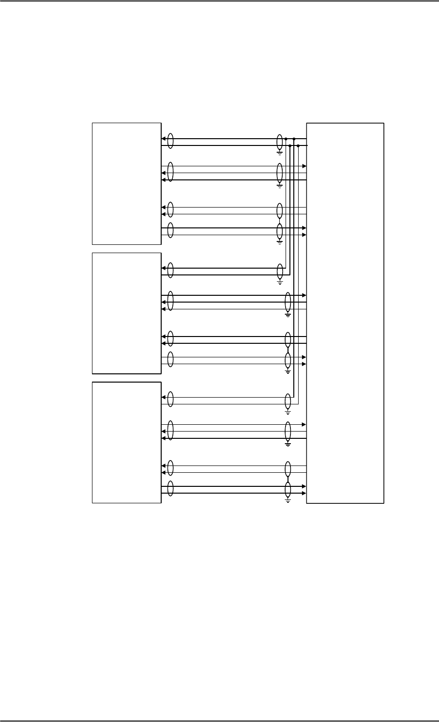
Electrical installation and wiring
5-54 Chapter 5: Installation 98-124743-F
5.3.12 Wiring WH-10 handsets
Overview
The following drawing shows the wiring of WH-10 handsets.
Figure 5-26: Wiring WH-10 handsets
+5,1*(5%
$
%
(
/
.
8
5
-
0
:+
+DQGVHW
9'&+DQGVHW6XSSO\
&KDVVLV*URXQGDQG+DQGVHW3RZHU5HWXUQ
+$1'6(7+22.6ZLWFK
+5,1*(5$
:/,1(7;
+5,1*(5%
$
%
(
/
.
8
5
-
0
:+
+DQGVHW
+$1'6(7+22.6ZLWFK
+5,1*(5$
+5,1*(5%
$
%
(
/
.
8
5
-
0
:+
+DQGVHW
+$1'6(7+22.6ZLWFK
+5,1*(5$
:/,1(7;
:/,1(5;
:/,1(5;
73
73
%3
%3
%3
73
73
73
73
77$
6'8
%3
%3
%3
73
73
73
73
%3
%3
%3
73
73
73
73
:/,1(5;
:/,1(7;
:/,1(7;
:/,1(5;
:/,1(7;
:/,1(7;
:/,1(5;
:/,1(5;
+DQGVHW
,QWHUIDFH
+DQGVHW
,QWHUIDFH
+DQGVHW
,QWHUIDFH
1RWH9DQG&KDVVLV*URXQGPXVWEHFRQQHFWHGDVFORVHDVSRVVLEOHWR7373

Electrical installation and wiring
98-124743-F Chapter 5: Installation 5-55
WH-10 pins
The below list shows the pins used for the WH-10 interfaces on the SDU.
Pin no. Name/Description
TP3 Chassis Ground and Handset Power Return
TP4 +28 V DC/600 mA Handset Supply
TP10 Handset #1 Audio In Hi / Cockpit Voice Audio #1 In Hi
TP11 Handset #1 Audio In Lo / Cockpit Voice Audio #1 In Lo
TP12 Handset #1 Audio Out Hi / Cockpit Voice Audio #1 Out Hi
TP13 Handset #1 Audio Out Lo / Cockpit Voice Audio #1 Out Lo
BP82 WH-10/MagnaStar Hook Switch #1. Discrete input.
BP83 WH-10/MagnaStar Ringer Output A1. Discrete I/O.
BP84 WH-10/MagnaStar Ringer Output B1. Discrete output.
TP15 Handset #2 Audio In Hi
TP16 Handset #2 Audio In Lo
TP17 Handset #2 Audio Out Hi
TP18 Handset #2 Audio Out Lo
BP85 WH-10/MagnaStar Hook Switch #2. Discrete input.
BP86 WH-10/MagnaStar Ringer Output A2. Discrete I/O.
BP87 WH-10/MagnaStar Ringer Output B2. Discrete output.
TP21 Handset #3 Audio In Hi
TP22 Handset #3 Audio In Lo
TP23 Handset #3 Audio Out Hi
TP24 Handset #3 Audio Out Lo
BP55 WH-10/MagnaStar Hook switch #3
BP89 WH-10/MagnaStar Ringer Output A3. Discrete I/O.
BP90 WH-10/MagnaStar Ringer Output B3
Table 5-41: SDU pins for WH-10 interface

Electrical installation and wiring
5-56 Chapter 5: Installation 98-124743-F
Description of WH-10 interfaces
Up to three WH-10 systems can be connected to the AVIATOR 700 system, using the
interfaces #1, #2 or #3.
For further information on the interfaces, see SDU pins for 4-wire interfaces on page 5-51.
Apart from the handset interfaces, the SDU has a number of discrete inputs/outputs used
for MagnaStar/WH-10 systems. For information on these interfaces, see Discretes for WH-
10 handset systems on page 5-56.
5.3.13 Discretes for WH-10 handset systems
The below list shows the discretes used for the MagnaStar/WH-10 interfaces on the SDU.
For more information on the discrete types, refer to Description of the discrete types on
page 5-68.
Note
The 4-wire handset system #1, #2 and #3 interfaces are used for either the 4-Wire
Handset system, MagnaStar, ICS-200, 2.4GHz Cordless or WH-10 phones, as
configurations share the same interface. For information on possible
combinations, see Configuration of wired handset interfaces on page 5-49.
The handset interfaces must be configured in the Aero-SDU Configuration
Program.
Pin no. Name/Description Discrete Type
BP54 MagnaStar: Satcom Service Unavailable Lamp Driver output
BP55 WH-10/MagnaStar Hook switch #3 WOW input
BP82 WH-10/MagnaStar Hook Switch #1 WOW input
BP83 WH-10/MagnaStar Ringer Output A1 Lamp Driver output
BP84 WH-10/MagnaStar Ringer Output B1 Lamp Driver output
BP85 WH-10/MagnaStar Hook Switch #2 WOW input
BP86 WH-10/MagnaStar Ringer Output A2 Lamp Driver output
BP87 WH-10/MagnaStar Ringer Output B2 Lamp Driver output
BP89 WH-10/MagnaStar Ringer Output A3 Lamp Driver output
BP90 WH-10/MagnaStar Ringer Output B3 Lamp Driver output
Table 5-42: SDU discretes for MagnaStar/WH-10 systems
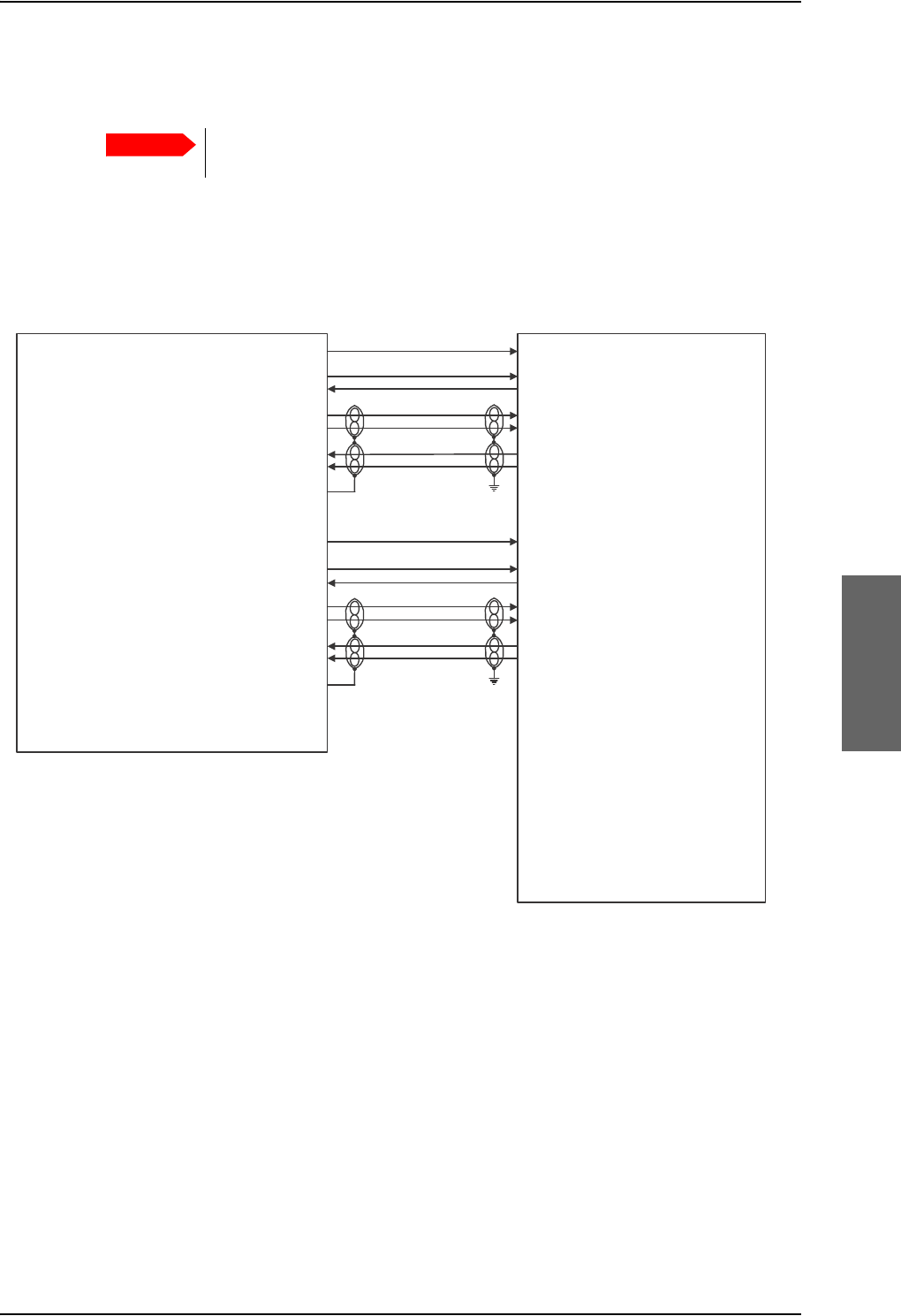
Electrical installation and wiring
98-124743-F Chapter 5: Installation 5-57
5.3.14 Wiring ICS-200 telephone system
Overview
The following drawing shows the wiring of the ICS-200 telephone system.
Important
When simultaneously operating the AVIATOR 700 over the Inmarsat network
and the ICS-200 there is a potential risk of interference.
Figure 5-27: Wiring ICS-200 Iridium Communication System interface
%3
%3
%3
73
73
73
73
%3
%3
%3
73
73
73
73
6ORW%&
6ORW$$
6ORW$$
6ORW$$
6ORW$$
6ORW$$
6ORW$$
6ORW$$
6ORW%&
6ORW$%
6ORW$%
6ORW$%
6ORW$%
6ORW$%
6ORW$%
6ORW$%
127(
7KLVZLULQJGLDJUDPRQO\DGGUHVVHVWKH,&6LQWHUIDFHVWRWKH77$6'8
)RUDQ\DGGLWLRQDO,&6LQVWDOODWLRQLQIRUPDWLRQUHIHUWRWKHDSSOLFDEOH,&6
LQVWDOODWLRQGRFXPHQWDWLRQ
+DQGVHW
,QWHUIDFH
+DQGVHW
,QWHUIDFH
,&6 77$6'8
287387
5,1*287387
2))+22.,1387
63($.(5+,
63($.(5/2
0,&+,
0,&/2
6+,(/'
287387
5,1*287387
2))+22.,1387
63($.(5+,
63($.(5/2
0,&+,
0,&/2
6+,(/'
&KDQDYDLO
5LQJHU,QSXW
+RRN6ZLWFK2XWSXW
$XGLR,Q+L
$XGLR,Q/R
$XGLR2XW+L
$XGLR2XW/R
&KDQDYDLO
5LQJHU,QSXW
+RRN6ZLWFK2XWSXW
$XGLR,Q+L
$XGLR,Q/R
$XGLR2XW+L
$XGLR2XW/R
%3
%3
%3
73
73
73
73
&KDQDYDLO
5LQJHU,QSXW
+RRN6ZLWFK2XWSXW
$XGLR,Q+L
$XGLR,Q/R
$XGLR2XW+L
$XGLR2XW/R
+DQGVHW
,QWHUIDFH
$OWHUQDWLYHLQWHUIDFHIRUFRQQHFWLQJ
,&6KDQGVHWLQWHUIDFHRU
1RWHWKDW$QQXQFLDWRU%3LVQRW
DYDLODEOHLIWKLVRSWLRQLVXVHG
^
+DQGVHW
,QWHUIDFH
+DQGVHW
,QWHUIDFH

Electrical installation and wiring
5-58 Chapter 5: Installation 98-124743-F
Pins on SDU for ICS-200 telephone system
The below list shows the pins used for the ICS-200 interface on the SDU.
Pin no. Name/Description
TP10 Handset #1 Audio In Hi
TP11 Handset #1 Audio In Lo
TP12 Handset #1 Audio Out Hi
TP13 Handset #1 Audio Out Lo
BP82 ICS-200 Ringer Input #1
BP83 ICS-200 Chan avail
BP84 ICS-200 Hook Switch Output #1
TP15 Handset #2 Audio In Hi
TP16 Handset #2 Audio In Lo
TP17 Handset #2 Audio Out Hi
TP18 Handset #2 Audio Out Lo
BP85 ICS-200 Ringer Input #2
BP86 ICS-200 Chan avail
BP87 ICS-200 Hook Switch Output #2
BP54 Satcom Service Unavailable
TP21 Handset #3 Audio In Hi
TP22 Handset #3 Audio In Lo
TP23 Handset #3 Audio Out Hi
TP24 Handset #3 Audio Out Lo
BP55 ICS-200 Ringer Input #3
BP89 ICS-200 Chan avail
BP90 ICS-200 Hook Switch Output #3
Table 5-43: SDU pins for ICS-200 interface

Electrical installation and wiring
98-124743-F Chapter 5: Installation 5-59
Description of Iridium ICS-200 interface
The Iridium Communication System ICS-200 can be connected to the SDU, providing the
possibility of routing calls from the AVIATOR 700 system to the Iridium satellite network.
For further information on the handset interfaces, see SDU pins for 4-wire interfaces on
page 5-51.
Apart from the handset interfaces, the SDU uses the discrete input/output Satcom Service
Unavailable.
Note
The 4-wire handset system #1, #2 and #3 interfaces are used for either the 4-Wire
Handset system, MagnaStar, ICS-200, 2.4GHz Cordless or WH-10 phones, as
configurations share the same interface. For information on possible
combinations, see Configuration of wired handset interfaces on page 5-49.
The handset interfaces must be configured in the Aero-SDU Configuration
Program.
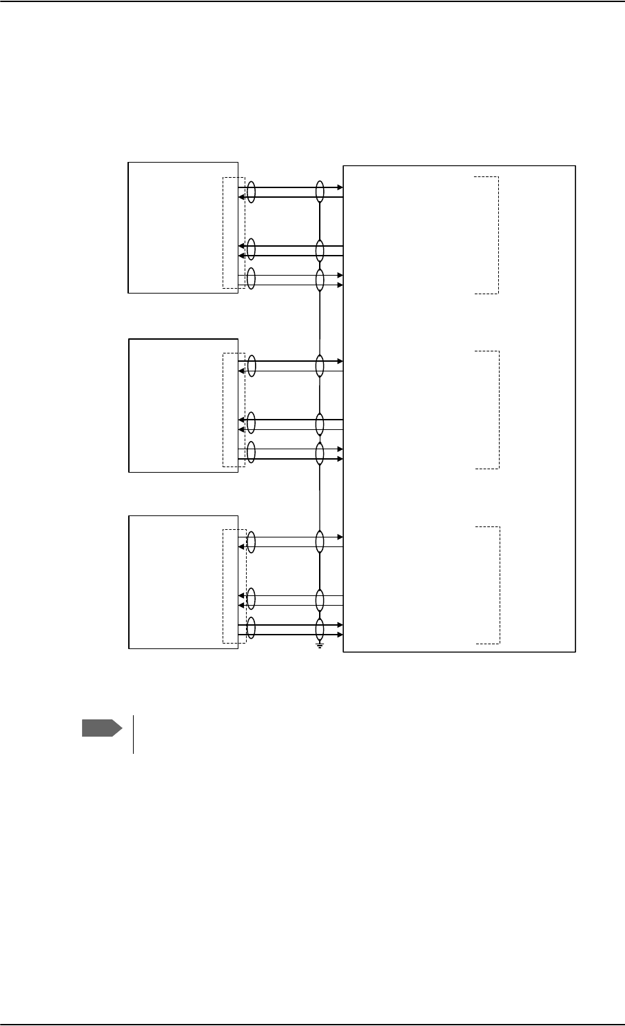
Electrical installation and wiring
5-60 Chapter 5: Installation 98-124743-F
5.3.15 Wiring 2.4GHz Cordless (4-wire) phone
Overview
The following drawing shows the wiring of 2.4GHz Cordless 4-wire phones.
Figure 5-28: Wiring 2.4GHz Cordless 4-wire phones
Note
The power for the 2.4GHz Cordless base unit must be supplied from an external
power supply. See the 2.4GHz Cordless manual for details.
*+]
&RUGOHVV
%DVH8QLW
7[/R
%3
%3
73
73
73
73
77$
6'8
%3
%3
73
73
73
73
%3
%3
73
73
73
73
7[+L
+DQGVHW
,QWHUIDFH
*+]
&RUGOHVV
%DVH8QLW
*+]
&RUGOHVV
%DVH8QLW
-
-
-
5[+L
5[/R
5LQJLQ
+RRN
6ZLWFK
7[/R
7[+L
5[+L
5[/R
5LQJLQ
+RRN
6ZLWFK
7[/R
7[+L
5[+L
5[/R
5LQJLQ
+RRN
6ZLWFK
:+0DJQD6WDU+RRN6ZLWFK
:+0DJQD6WDU5LQJHU2XWSXW$
+DQGVHW$XGLR2XW+L
+DQGVHW$XGLR2XW/R
+DQGVHW$XGLR,Q+L
+DQGVHW$XGLR,Q/R
:+0DJQD6WDU+RRN6ZLWFK
:+0DJQD6WDU5LQJHU2XWSXW$
+DQGVHW$XGLR2XW+L
+DQGVHW$XGLR2XW/R
+DQGVHW$XGLR,Q+L
+DQGVHW$XGLR,Q/R
+DQGVHW$XGLR2XW+L
+DQGVHW$XGLR2XW/R
+DQGVHW$XGLR,Q+L
+DQGVHW$XGLR,Q/R
:+0DJQD6WDU+RRN6ZLWFK
:+0DJQD6WDU5LQJHU2XWSXW$
+DQGVHW
,QWHUIDFH
+DQGVHW
,QWHUIDFH

Electrical installation and wiring
98-124743-F Chapter 5: Installation 5-61
Pins for 2.4GHz Cordless (WH-10) interfaces
The below list shows the pins used for the 2.4GHz Cordless (WH-10) interfaces on the SDU.
Pin no. Name/Description
TP10 Handset #1 Audio In Hi
TP11 Handset #1 Audio In Lo
TP12 Handset #1 Audio Out Hi
TP13 Handset #1 Audio Out Lo
BP82 WH-10/MagnaStar Hook Switch #1
BP83 WH-10/MagnaStar Ringer Output A1
TP15 Handset #2 Audio In Hi
TP16 Handset #2 Audio In Lo
TP17 Handset #2 Audio Out Hi
TP18 Handset #2 Audio Out Lo
BP85 WH-10/MagnaStar Hook Switch #2
BP86 WH-10/MagnaStar Ringer Output A2
TP21 Handset #3 Audio In Hi
TP22 Handset #3 Audio In Lo
TP23 Handset #3 Audio Out Hi
TP24 Handset #3 Audio Out Lo
BP55 WH-10/MagnaStar: Hook switch #3
BP89 WH-10/MagnaStar Ringer Output A3
Table 5-44: SDU pins for 2.4GHz Cordless (WH-10) interface

Electrical installation and wiring
5-62 Chapter 5: Installation 98-124743-F
Description of 2.4GHz Cordless interfaces
Up to three 2.4GHz Cordless Handsets can be connected to the AVIATOR 700 system,
using the interfaces #1, #2 or #3.
For further information on the interfaces, see SDU pins for 4-wire interfaces on page 5-51.
Apart from the handset interfaces, the SDU has a number of discrete inputs/outputs used
for MagnaStar/WH-10 systems. For information on these interfaces, see Discretes for WH-
10 handset systems on page 5-56.
Note
The 4-wire handset system #1, #2 and #3 interfaces are used for either the 4-Wire
Handset System, MagnaStar, 2.4GHz Cordless or WH-10 phones, as configurations
share the same interface. For information on possible combinations, see
Configuration of wired handset interfaces on page 5-49. Handset interface #4
can only be used for the 4-Wire Handset System.
The handset interfaces must be configured in the Aero-SDU Configuration
Program.
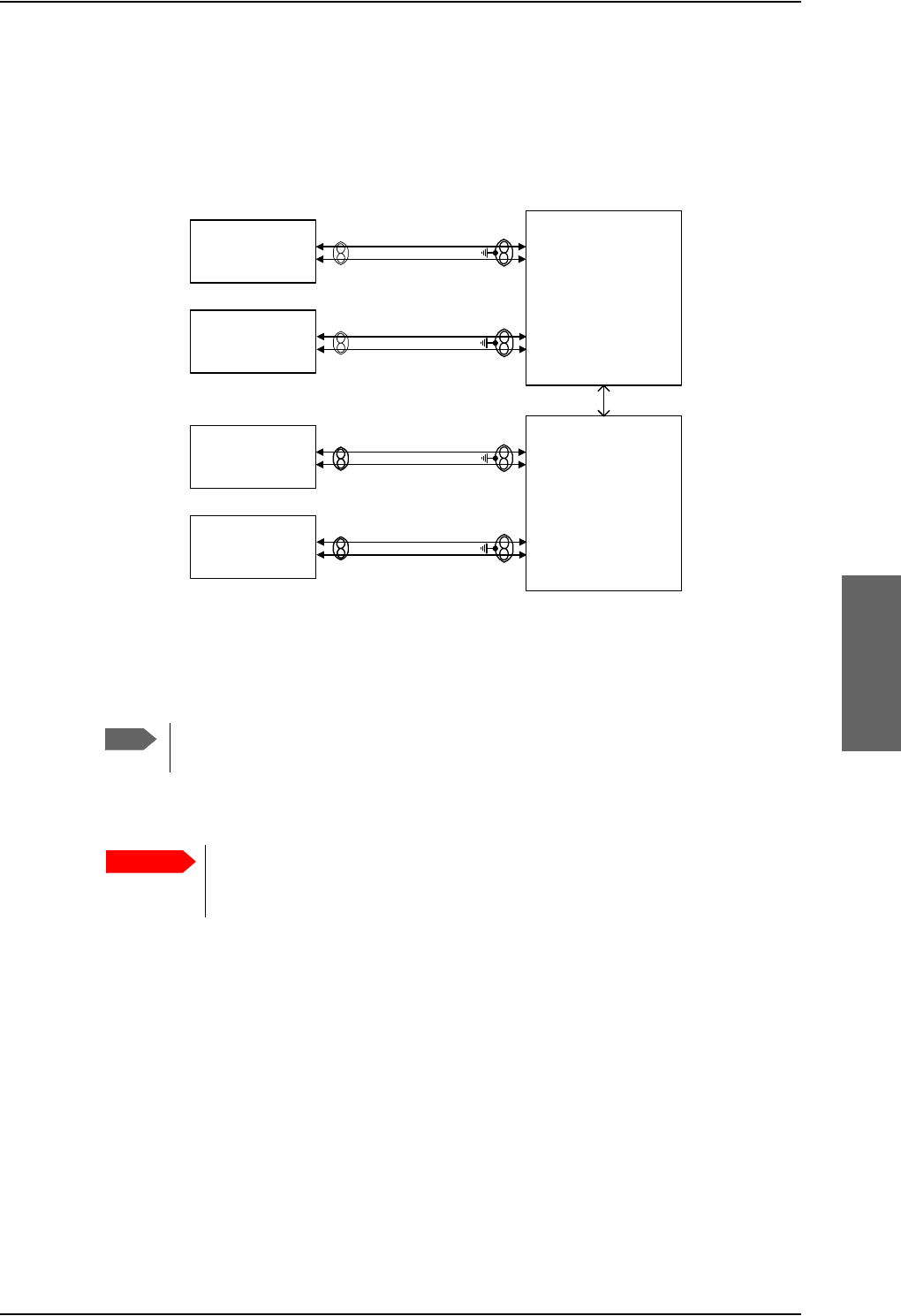
Electrical installation and wiring
98-124743-F Chapter 5: Installation 5-63
5.3.16 Wiring Sigma7 (2-wire) handsets
One to four Sigma7 handsets can be connected to the 2-wire interfaces of the AVIATOR
700 system. The following drawing shows the wiring of Sigma7 handsets.
Figure 5-29: Wiring Sigma7 handsets
The above wiring shows the connection for the non-backlit Sigma7 handset. The
backlit version Sigma7 handset uses pin 6 for Tip 1 and pin 3 for Ring 1.
Connect J1 on the Sigma7 handset to the rear receptacle of the SDU and/or SBU according
to the wiring drawing above.
In order for the volume in the Sigma7 handset to be sufficient, it is normally
necessary to adjust the “ear volume” using the menu system of the handset.
For information on how to do this, see Sigma7 setup on page 6-96.
For information on the 2-wire interface, see Pins for 2-wire interfaces on page 5-53.
Note
Important
:,5()$;02'(03276
6LJPD
&UDGOH
:,5()$;02'(03276
77$
6'8
73
73
73
73
-SLQ
-SLQ
6LJPD
&UDGOH
-SLQ
-SLQ
+DQGVHW,QWHUIDFH
+DQGVHW,QWHUIDFH
:,5()$;02'(03276
6LJPD
&UDGOH
:,5()$;02'(03276
77$
6%8
73
73
73
73
-SLQ
-SLQ
6LJPD
&UDGOH
-SLQ
-SLQ
+DQGVHW,QWHUIDFH
+DQGVHW,QWHUIDFH
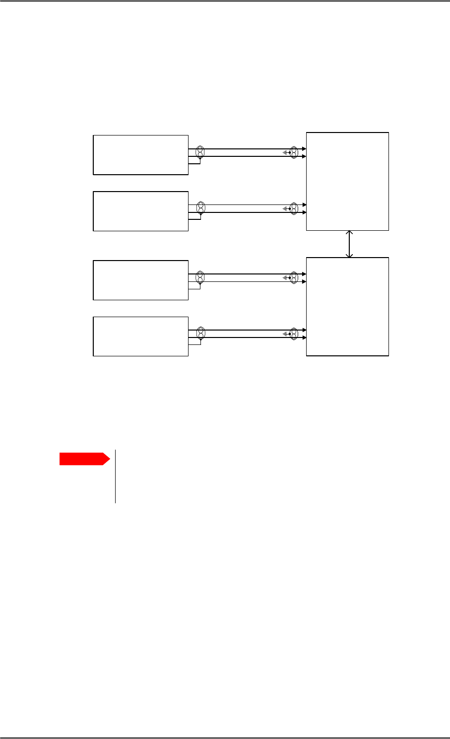
Electrical installation and wiring
5-64 Chapter 5: Installation 98-124743-F
5.3.17 Wiring ICG DECT Cordless Handset (2-wire) phone
One to four ICG DECT Cordless Handset phones can be connected to the 2-wire interfaces
of the AVIATOR 700 system. The following drawing shows the wiring of ICG DECT Cordless
Handset 2-wire phones.
Connect J2 on the base station of the ICG DECT Cordless Handset phone to the rear
receptacle of the SDU and/or SBU according to the wiring drawing above. The base station
is supplied together with the handset and cradle.
In order for the ICG DECT Cordless Handset phone to work properly, it is
normally necessary to make a few initial adjustments of the handset. For
information on how to do this, see ICG DECT Cordless Handset setup on
page 6-96.
For information on the 2-wire interface, see Pins for 2-wire interfaces on page 5-53.
Figure 5-30: Wiring 2.4GHz Cordless handsets
Important
:,5()$;02'(03276
*+]&RUGOHVV
%DVH8QLW
:,5()$;02'(03276
77$
6'8
73
73
73
73
-SLQ
-SLQ
-SLQ
*+]&RUGOHVV
%DVH8QLW
-SLQ
-SLQ
-SLQ
+DQGVHW,QWHUIDFH
+DQGVHW,QWHUIDFH
:,5()$;02'(03276
*+]&RUGOHVV
%DVH8QLW
:,5()$;02'(03276
77$
6%8
73
73
73
73
-SLQ
-SLQ
-SLQ
*+]&RUGOHVV
%DVH8QLW
-SLQ
-SLQ
-SLQ
+DQGVHW,QWHUIDFH
+DQGVHW,QWHUIDFH
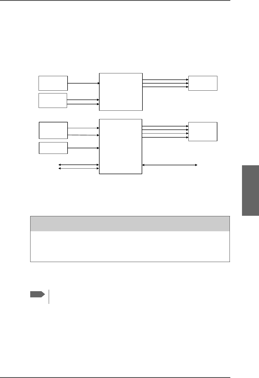
Electrical installation and wiring
98-124743-F Chapter 5: Installation 5-65
5.3.18 Wiring discretes
Discrete annunciators, Chime/Lamps Inhibit and WOW
The following drawing shows the wiring of discrete annunciators, Chime/Lamps Inhibit and
Weight-on-Wheels (WOW).
Pins for discrete annunciators
The following list shows the pins used for discrete annunciators:
Figure 5-31: Wiring discrete annunciators and Weight-on-Wheels
$QQXQFLDWRUV
$QQXQFLDWRU6HUYLFHDYDLODEOH
$QQXQFLDWRU&DOO
$QQXQFLDWRU)D[
%3
%3
%3
77$
6'8
:HLJKW2Q
:KHHOV
%3
%3
:R:LQSXW
:R:LQSXW
&KLPH/DPSV
,QKLELW
%3
&KLPH/DPSV,QKLELW
77$
6%8
'LVFUHWH
,QSXWV
:/$1(QDEOH
6%8Q2Q 73
73
$QQXQFLDWRUV
$QQXQFLDWRU6HUYLFHDYDLODEOH
$QQXQFLDWRU6%8IDLOHG
$QQXQFLDWRU,QFRPLQJFDOO
73
73
73
%3
73
&KLPH/DPSV,QKLELW
&KLPH/DPSV
,QKLELW
6SDUH,2
6SDUH,2 %3
%3
73 6SDUH,2RUIXWXUH+3$Q2Q
$QQXQFLDWRU0HVVDJHUHFHLYHG
SDU Pin Name/Description Specification of discrete
typea
a. The discrete interfaces are described in Description of the discrete types on page 5-68.
BP89 Annunciator #3 “Service Available” (Discrete I/O) Output: Lamp Driver
BP92 Annunciator #1 “Call” (Discrete I/O) Output: Lamp Driver
BP93 Annunciator #2 “Fax” (Discrete Output) Output: Lamp Driver
Table 5-45: SDU pins for discrete annunciators
Note
Annunciator #3 on pin BP89 is not available if you are using handset interface #3
for MagnaStar, 2.4GHz Cordless (4-wire) or WH-10 Handsets.

Table 5-46: SBU pins for discrete annunciators
TP27 Annunciator #3 “Service available” (Discrete I/O) Output: Lamp Driver
TP28 Annunciator #1 “Incoming call” (Discrete I/O) Output: Lamp Driver
TP29 Annunciator #2 “SBU failed” (Discrete I/O) Output: Lamp Driver
BP1 Annunciator #4 “Message received” (Discrete I/O) Output: Lamp Driver
Electrical installation and wiring
5-66 Chapter 5: Installation 98-124743-F
Function of discrete annunciators
The function of the SDU Annunciators is as follows:
• Annunciator #1 “Call”.
This Annunciator is used for signalling incoming voice calls. The Annunciator is “flashing”
like the Connection LED on a 4-Wire Handset (default setting) and is turned off when
the call is answered or terminated by the initiator.
• Annunciator #2 “Fax”.
This Annunciator is used for signalling incoming fax. The Annunciator is “steady ON”
until a receipt for the fax has been given in the handset (default setting).
• Annunciator #3 “Service Available”.
This Annunciator is used for indicating satcom service availability. The Annunciator is
“steady ON” when H+ service is available (default setting).
You can configure the behavior of the annunciators. To do this use the Aero-SDU
Configuration Program. While in the configuration select Ring Profiles, Annunciator
Behavior and select for each annunciator.
The function of the SBU annunciators is as follows:
• Annunciator #1 “Incoming call” (TP28)
Default behavior: Active (low) when a handset is ringing.
• Annunciator #2 “SBU Failed” (TP29).
Default behavior: Active (low) whenever a BITE with severity essential or fatal is active
on the SBU. (Fatal in this context means fatal locally on the SBU. When displayed at the
SDU any fatal error on the SBU will only cause an essential BITE to be raised at the SDU).
• Annunciator #3 “Service available” (TP27).
Default behavior: Active (low) when the SwiftBroadband Service is available.
• Annunciator #4 “Message received” (BP1).
Default behavior: Active (low) when a Message is received in the SBU.
SBU pin Name and description Discrete typea
a. The discrete interfaces are described in Description of the discrete types on page 5-68.

Electrical installation and wiring
98-124743-F Chapter 5: Installation 5-67
Pins for Chime/Lamps Inhibit input
Pins used for the Chime/Lamps Inhibit input:
Description of the Chime/Lamps Inhibit interfaces
The SDU and the SBU each have one discrete input for the Chime/Lamps Inhibit function.
This input is used to inhibit Satcom activation of the chime and call lights during take-off
and landing. The Inhibit function is activated by connecting this input to ground. The
Inhibit function of the SDU also activates the ring profile “TakeOfLandng”.
Polarity of the discrete annunciators and Chime/Lamps Inhibit input
The ring profiles are defined using the Aero-SDU Configuration Program where call
inhibit/non-inhibit is set up for each of the 4-wire and 2-wire interfaces and annunciators.
In the web interface you can change the polarity of the discrete annunciators and the
Chime/Lamps Inhibit input from Active low (default) to Active high. For instructions how to
do this see Configure the discrete I/O interfaces of the SBU on page 6-47.
Weight-On-Wheels (not currently in use)
The following list shows the pins used for Weight-On-Wheels (WOW):
The SDU has 2 discrete inputs for Weight-On-Wheels (WOW), which can detect whether
the aircraft is airborne or not. Currently this information is not used in the SDU.
The interpretation of the polarity (airframe DC ground or open circuit) of the input is
defined by the Configuration Module (WOW Active Polarity).
The Configuration Module also defines if WOW is installed or not. For further information,
see the online help in the Aero-SDU Configuration Program.
SDU Pin Name/Description Specification of discrete typea
a. The discrete interfaces are described in Description of the discrete types on page 5-68.
BP88 Chime/Lamps Inhibit Input Input: WOW (active low)
Table 5-47: SDU Pin for Chime/Lamps Inhibit input
SBU pin Name/description Specification of discrete type
TP13 Chime/Lamps Inhibit Discrete input (default: active low)
Table 5-48: SBU pin for Chime/Lamps Inhibit input
SDU Pin Name/Description Specification of discrete typea
a. The discrete interfaces are described in Description of the discrete types on page 5-68.
BP50 Weight-on-Wheels Input #1 Input: WOW
BP51 Weight-on-Wheels Input #2 Input: WOW
Table 5-49: SDU pins for WOW

Electrical installation and wiring
5-68 Chapter 5: Installation 98-124743-F
Pins for non-configurable discrete inputs on the SBU
The SBU has two non-configurable discrete inputs: one for SBU nON, one for WLAN Enable.
The below table shows the pin-out for the discrete inputs:
SBU nON (TP3): The SBU nON input is used to power the SBU on and off. Connect this
input to ground to turn on the SBU. The electrical specification is defined in Description of
the discrete types below.
WLAN Enable (TP5): WLAN Enable input is used to enable the WLAN interface. The input
is active low and the WLAN interface is kept disabled and reset as long as the input is at the
high state. When the input is connected to ground or to low state the WLAN interface will
be initialized and ready for use. When the WLAN interface is not enabled no RF is emitted
from the interface.
Description of the discrete types
Discrete type and description:
SBU pin Name/description
TP3 SBU nON input
TP5 WLAN Enable input
Table 5-50: SBU pins for discrete inputs
Discrete type Description
Lamp Driver The SDU and SBU have several discrete Lamp Driver outputs. The
output configuration forms a switch closure to ground. The electrical
specification for the Lamp type switch is:
Open switch hold-off voltage: max. +39.5 V DC
Closed switch voltage: max. 1 V DC at 500 mA
Open switch resistance (OFF): min. 100 k
Discrete input The discrete input detects the following states:
“Open” voltage: 7 V DC to 39.5 V DC or 100 k to ground.
“Short” voltage: 0 ±3.5 V DC or 1500 to ground.
Input characteristics:
Reaction time: <500 ms.
The internal interface is diode-isolated for parallel connection
externally to any other LRU(s), with at least 200 k of isolation, when
power is not applied.
Table 5-51: Specification of discrete types

Electrical installation and wiring
98-124743-F Chapter 5: Installation 5-69
5.3.19 Wiring Cockpit Voice interface
Introduction
The Cockpit Voice interface must be wired to the Audio Management System (AMS) and an
Audio Control Panel (ACP) or similar. Figure 5-32: shows a typical Cockpit Voice
installation. Pay attention to the drawing notes:
NOTES:
[1]The balanced audio outputs from the SDU (TP10, TP11, TP17 and TP18) are not
transformer coupled. Do not connect HI or LO output to ground.
[2]Off-hook is signalled in 3 ways (per configuration). Use either
• Push-To-Talk (PTT) switch
•Latched Audio Control Panel switch
•MCDU line switch
[3]If the AMS has unbalanced audio inputs or outputs, transformers should be inserted in
the audio lines, to convert the balanced signals to unbalanced and vice versa. Figure 5-33:
shows a typical installation for an AMS with unbalanced audio inputs/ outputs. The
Universal Interface Amplifier model 270-16 from Northern Airborne Technology (NAT)
has built-in transformers. Alternatively the model AA34-300 may be used (with the same
I/O pin configuration). The settings of the Universal Interface Amplifier are listed in Table 5-
53 on page 5-72 and Table 5-54 on page 5-73.
Northern Airborne Technology (NAT) part numbers
Part name Part number
Universal Interface Amplifier Model 270-16
Universal Radio Interface Model AA34-300
Table 5-52: Northern Airborne Technology (NAT) part numbers.
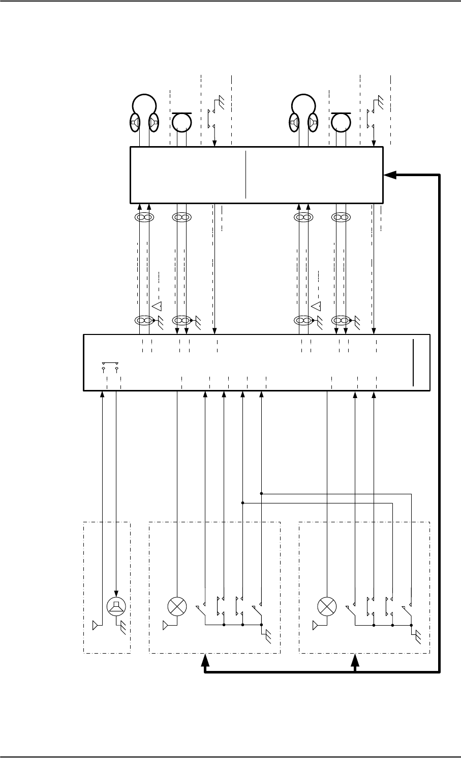
Electrical installation and wiring
5-70 Chapter 5: Installation 98-124743-F
Typical Cockpit Voice installation
Figure 5-32: Typical Cockpit Voice installation
&DOO/LJKW
9
$XGLR&RQWUROSDQHO$&3
9 &+,0(
&XUUHQWIURPFKLPH
&XUUHQWWRFKLPH
&DOO&DQFHOQRWH>@
$&30LF2QQRWH>@
&KLPH/DPSV,QKLELW
&KLPH5HVHW
&DOO/LJKW
9
$XGLR&RQWUROSDQHO$&3
&DOO&DQFHOQRWH>@
$&30LF2QQRWH>@
&KLPH5HVHW
&KLPH/DPSV,QKLELW
&KLPH6LJQDO&RQWDFW
&KLPH6LJQDO&RQWDFW
$XGLR
0DQDJHPHQW
6\VWHP
$06
+HDGVHW3KRQH
+HDGVHW0LFURSKRQH
377VZLWFKQRWH>@
+HDGVHW3KRQH
+HDGVHW0LFURSKRQH
377VZLWFKQRWH>@
77$
6'8
%3
%3
%3 73
73
73
73
1RWH>@
73
73
73
73
1RWH>@
%3
%3
%3
%3
%3
%3
%3
%3
%3
3770LF2Q
3770LF2Q
QRWH>@
QRWH>@
&39$XGLR2XW+L
&39$XGLR2XW/R
&39$XGLR,Q+L
&39$XGLR,Q/R
9RLFH0LF2Q,QSXW
&39$XGLR,Q+L
&39$XGLR,Q/R
9RLFH0LF2Q,QSXW
&39$XGLR2XW+L
&39$XGLR,Q/R
9RLFH&DOO/LJKW2XWSXW
9RLFH&DOO/LJKW2XWSXW
9RLFH0LF2Q,QSXW
&DOO&DQFHO,QSXW
&KLPH5HVHW,QSXW
&KLPH/DPSV,QKLELW,QSXW
9RLFH0LF2Q,QSXW
&DOO&DQFHO,QSXW
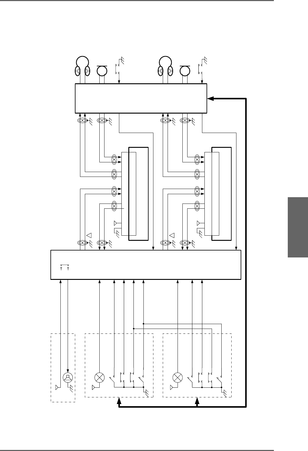
Electrical installation and wiring
98-124743-F Chapter 5: Installation 5-71
Cockpit Voice with unbalanced AMS audio interface
Figure 5-33: Typical Cockpit Voice installation with unbalanced AMS audio interface
&DOO/LJKW
9
$XGLR&RQWURO3DQHO$&3
9 &+,0(
&XUUHQWIURPFKLPH
&XUUHQWWRFKLPH
&DOO&DQFHOQRWH>@
$&30LF2QQRWH>@
&KLPH/DPSV,QKLELW
&KLPH5HVHW
&DOO/LJKW
9
$XGLR&RQWURO3DQHO$&3
&DOO&DQFHOQRWH>@
$&30LF2QQRWH>@
&KLPH5HVHW
&KLPH/DPSV,QKLELW
77$
6'8
%3
%3
%3 73
73
73
73
1RWH>@
'%)
$XGLR
0DQDJHPHQW
6\VWHP
$06
+,
/2
+,
/2
+HDGVHW3KRQH
+HDGVHW0LFURSKRQH
377VZLWFKQRWH>@
9
8QLYHUVDO,QWHUIDFH$PSOLILHUQRWH>@
0RGHORU0RGHO$$
73
73
73
73
&39$XGLR2XW+L
$XGLRWR6DW&RP
+,
/2
$XGLRIURP6DW&RP
+,
/2
1RWH>@
+HDGVHW3KRQH
+HDGVHW0LFURSKRQH
377VZLWFKQRWH>@
9
8QLYHUVDO,QWHUIDFH$PSOLILHUQRWH>@
0RGHORU0RGHO$$
'%)
%3
%3
%3
%3
%3
%3
%3
%3
%3
3770LF2Q
3770LF2Q
QRWH>@
QRWH>@
&39$XGLR2XW/R
&39$XGLR,Q+L
&39$XGLR,Q/R
&39$XGLR2XW+L
&39$XGLR2XW/R
&39$XGLR,Q+L
&39$XGLR,Q/R
$XGLRIURP6DW&RP
$XGLRWR6DW&RP
9RLFH0LF2Q,QSXW
9RLFH0LF2Q,QSXW
&KLPH6LJQDO&RQWDFW
&KLPH6LJQDO&RQWDFW
9RLFH&DOO/LJKW2XWSXW
9RLFH0LF2Q,QSXW
&DOO&DQFHO,QSXW
&KLPH5HVHW,QSXW
&KLPH/DPSV,QKLELW,QSXW
9RLFH&DOO/LJKW2XWSXW
9RLFH0LF2Q,QSXW
&DOO&DQFHO,QSXW

Electrical installation and wiring
5-72 Chapter 5: Installation 98-124743-F
NAT, Universal Interface Amplifier model 270-16 settings
Switch/Jumper/
Adjustment ID NAT, Universal Interface Amplifier model 270-16 settings
9V bias, MS3 The SDU does not provide microphone DC power. If the microphone
needs DC-power, and if the AMS does not provide DC power this
switch shall be set to "9V bias".
Load Sel. MS4 Set switch to 600 Ohm (Audio output channel to AMS Audio Input).
Load Sel. MS5 Set switch to 600 Ohm (Mic. output channel to SDU Audio Input).
Mic SDTN Set mic. side tone level to minimum (side tone is handled by the
SDU).
Mic. Gain The mic. gain can be adjusted, but it is preferred to use the SDU
adjustment capability (approximately 18dB). As starting point the
mic. gain should be set to maximum.
Rcvr. level The receiver level (headset phone level) can be adjusted, but it is
preferred to use the SDU adjustment capability (approximately
18dB). As starting point the Rcvr. level should be set to maximum,
and the audio output from the SDU should be adjusted to match
other system components (VHF radios etc).
Table 5-53: Universal Interface Amplifier model 270-16 settings

Electrical installation and wiring
98-124743-F Chapter 5: Installation 5-73
NAT, Universal Interface Amplifier model AA34-300 settings
Switch/Jumper/
Adjustment ID NAT, Universal Interface Amplifier model AA34-300 settings
Microphone DC bias, S1 The SDU does not provide microphone DC power. If the
microphone needs DC-power, and if the AMS does not provide
DC power this switch shall be set to "closed".
Microphone gain C1/C2 Set switch to "C2" in order to select the microphone amplifier
and the transformer coupling.
Mic. output impedance,
JP1
Set jumper JP1 to 150 Ohm, position "B-C" (Mic. output
channel to SDU Audio Input).
Audio Output
Impedance JP2
Set jumper JP2 to 600 Ohm position "B-C" (Audio output
channel to AMS Audio Input).
Mic S/T level Set mic. side tone level to minimum (side tone is handled by
the SDU).
Mic. Level The mic. gain can be adjusted, but it is preferred to use the
SDU adjustment capability (approximately 18dB). As starting
point the mic. gain should be set to maximum.
RX level The receiver level (headset phone level) can be adjusted, but it
is preferred to use the SDU adjustment capability
(approximately 18dB). As starting point the RX level should be
set to maximum, and the audio output from the SDU should
be adjusted to match other system components (VHF radios
etc).
Table 5-54: Universal Interface Amplifier model AA34-300 settings

Electrical installation and wiring
5-74 Chapter 5: Installation 98-124743-F
SDU pins for Cockpit Voice
SDU
Pin Name/Description Specification
BP52 CP Voice Chime Signal Contact #1;
Current from Chime
Relay type, forms a circuit closure
between BP52 and BP53 a
a. Chime relay contact specification (BP52,BP53):
Maximum current: 1.0 A.
Maximum hold-off voltage (open circuit): 36.0 V.
BP53 CP Voice Chime Signal Contact #2;
Current to Chime
Relay type, forms a circuit closure
between BP52 and BP53 a
BP82 CP Voice Call Cancel Input #1
(Discrete I)
Input: WOW (active low) b
b. The discrete interfaces are described in Description of the discrete types on page 5-68.
BP83 CP Voice Mic On Input #1 (Discrete
I/O)
Input: WOW (active low) b
BP84 CP Voice Call Light Output #1
(Discrete O)
Output: Lamp driver b
BP85 CP Voice Call Cancel Input #2
(Discrete I)
Input: WOW (active low) b
BP86 CP Voice Mic On Input #2
(Discrete I/O)
Input: WOW (active low) b
BP87 CP Voice Call Light Output #2
(Discrete O)
Output: Lamp driver b
BP88 Chime/Lamps Inhibit Input
(Discrete I)
Input: WOW (active low) b
BP91 CP Voice Chime Reset Input
(Discrete I)
Input: WOW (active low) b
TP10 Cockpit Voice Audio #1 In Hi Balanced input. Impedance > 35 kOhm c
c. Dynamic input range: 0.12 VRMS to 1.5VRMS.
TP11 Cockpit Voice Audio #1 In Lo Balanced input. Impedance > 35 kOhm c
TP12 Cockpit Voice Audio #1 Out Hi Balanced output. Impedance < 20 Ohm d
d. Rated output power into 600 Ohm: > 40mW (4.9VRMS).
The outputs are NOT transformer coupled, and must not be shorted to ground.
Minimum load impedance: >= 250 Ohm.
TP13 Cockpit Voice Audio #1 Out Lo Balanced output. Impedance < 20 Ohm d
TP15 Cockpit Voice Audio #2 In Hi Balanced input. Impedance > 35 kOhm c
TP16 Cockpit Voice Audio #2 In Lo Balanced input. Impedance > 35 kOhm c
TP17 Cockpit Voice Audio #2 Out Hi Balanced output. Impedance < 20 Ohm d
TP18 Cockpit Voice Audio #2 Out Lo Balanced output. Impedance < 20 Ohm d
Table 5-55: SDU pins for Cockpit Voice interface

Electrical installation and wiring
98-124743-F Chapter 5: Installation 5-75
Description of the Cockpit Voice interface
CP Voice Chime Signal Contact #1/#2 (BP52, BP53)
The solid state relay drives a chime, that is sounded on incoming calls (ground-to-air call),
and per configuration on outgoing calls (air-to-ground calls), when the line is connected and
ready (single stroke or multi stroke chime).
CP Voice Call Light Output #1/#2 (BP84, BP87)
The discrete outputs drive the call lights, that are turned on at incoming and outgoing calls.
The lamps are either flashing or steady on (per configuration), until off-hook.
CP Voice Mic On Input #1/#2 (BP83, BP86)
The discrete inputs are used for entering the off-hook state on incoming and outgoing calls.
The input may be wired (per configuration) to the Push-To-Talk (PTT) switch, or the latched
Mic On switch on the Audio Control Panel (ACP).
PTT switch wiring: The off-hook state is entered on the first high-to-low transition.
ACP switch wiring: When the input is low, the state is off-hook. When the input is high the
state is on-hook.
CP Voice Call Cancel Input #1/#2 (BP82, BP85)
If the above Mic. On inputs are configured to PTT switch wiring, the Call Cancel inputs may
be used for entering on-hook state. The input reacts on a high-to-low transition.
CP Voice Chime Reset Input (BP91)
The discrete input is used for silencing the chime, but off-hook state will not be entered.
The input reacts on a high-to-low transition.
Chime/Lamps Inhibit Input (BP88)
The discrete input is used for inhibiting the Call Lamps and the Chime from becoming
active, and is typically used during take-off and landing. The inhibit function is active as
long as the input is kept low.
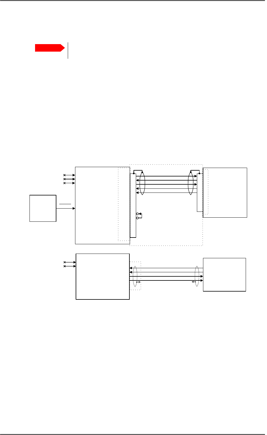
Electrical installation and wiring
5-76 Chapter 5: Installation 98-124743-F
5.3.20 Wiring the Maintenance interfaces and Reset
Maintenance PC, CM Write Enable, SDU Reset and ATE
The following drawing shows the wiring of:
• the RS-232 Maintenance PC connection on the SDU,
• the LAN Maintenance PC connection on the SBU,
•SDU Reset,
• Write enable for the SDU Configuration Module and
• ATE interface (for factory use only - do not connect!)
Important
Make sure that there is no cable connected to the SDU or SBU Maintenance
connector when the aircraft is airborne.
Figure 5-34: Wiring Maintenance PC and Reset
77$
6'8
5(6(7 %3
)3
)3
)3
)3
)3
)3
)3
*1'3RZHU5HWXUQ
0DLQWHQDQFH
3&
56&576
56&5;'
56&7;'
56&&76
%3$7(
%3$7(
%3$7(
'RQRWFRQQHFW
6'8
5HVHW
'%)
'%0
'%)
&0:ULWH(QDEOH
'DWD&DEOH77
9'&
'%0
77$
6%8
73$7(
73$7( )3
)3
)3
)3
0DLQWHQDQFH
3&
)5217&211(&7255-
5['
5['
7['
7['
5-
'RQRWFRQQHFW

Electrical installation and wiring
98-124743-F Chapter 5: Installation 5-77
Pins for SDU RS-232 Maintenance PC interface and CM Write Enable (SDU)
The following list shows the SDU pins used for RS-232 PC interface and for CM Write
Enable. Both interfaces are included in the TT 37-112940 data cable described at the end
of this section.
Description of SDU RS-232 Maintenance PC interface and CM Write Enable
The SDU has a PC interface at the front connector, supporting the RS-232 standard. The
front PC interface can also be used for uploading software.
The interface is configured as DCE on the SDU (i.e. TxD + RTS are inputs and RxD + CTS are
outputs).
The PC interface has the following characteristics:
• Baud rate: 115.2 kbps fixed
• Data bits: 8
•Parity: None
•Stop bit: 1
• Flow control: Hardware (RTS/CTS only)
The Write Enable Input - FP15 - enables write cycles to the write protected area in the
Configuration Module. FP15 must be connected to +12 V DC (FP8) in order to have access
to the write protected area. Electrical specifications:
Enable Write cycles: +10.0 V VFP15 +13.0 V
Write Protected: VFP15 +1.9 V
SDU Pin Name/Description
FP10 TxD Input
FP11 RxD Output
FP12 RTS Input
FP13 CTS Output
FP9 GND, Power Return (for +12 V DC)
FP8 +12 V DC/120 mA
FP15 Configuration Module Write Enable In
Table 5-56: SDU pins for RS-232 PC interface
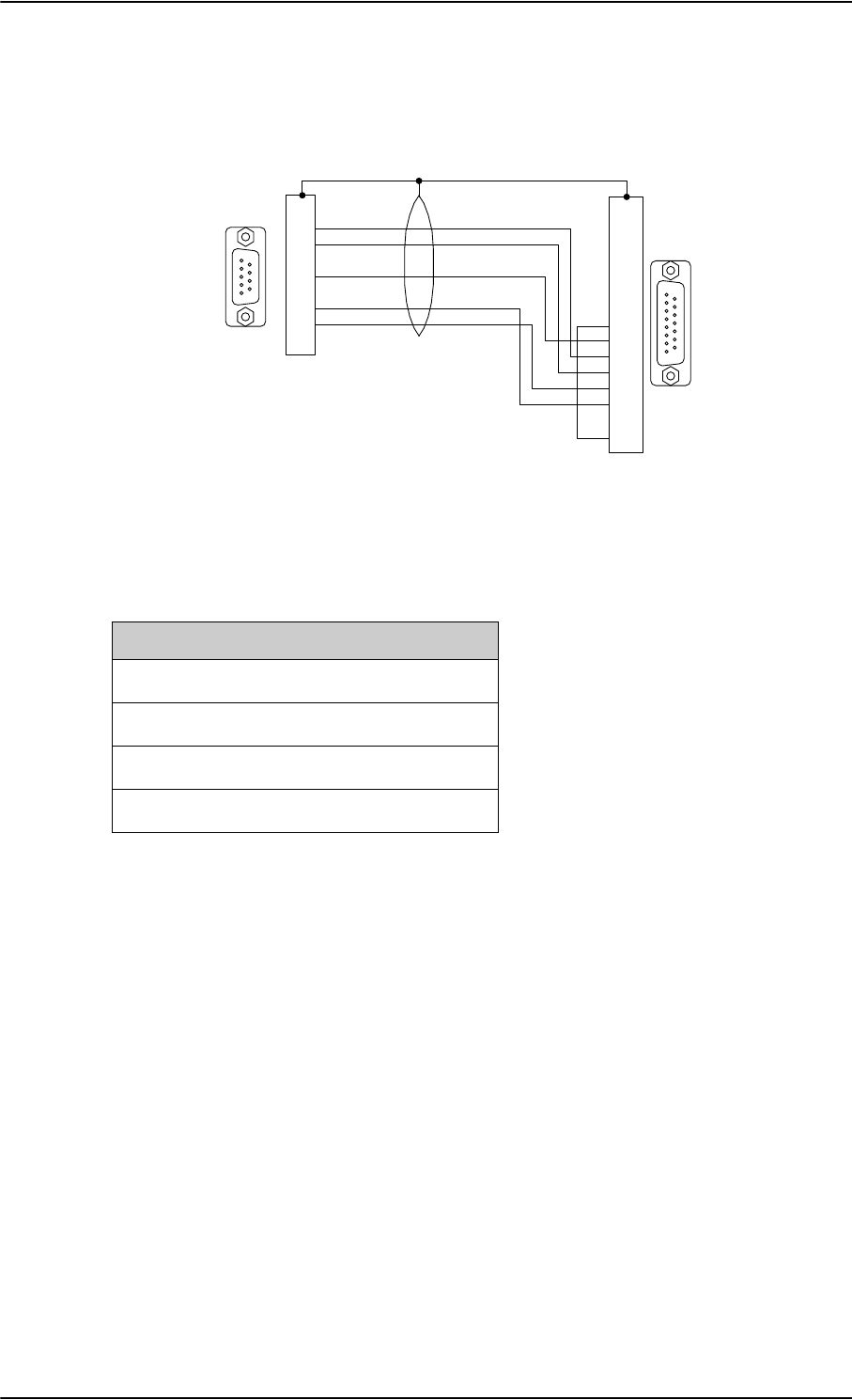
Electrical installation and wiring
5-78 Chapter 5: Installation 98-124743-F
The following drawing shows the wiring of the maintenance cable for the SDU front
connector.
Pins for the Maintenance interface on SBU
The following list shows the pins used for the Maintenance interface on the SBU.
Description of the Maintenance interface on the SBU
Use the Maintenance interface on the front of the SBU for configuration and maintenance
purpose, i.e. for tasks like configuring RF cable settings for the installation, satcom antenna
setup, navigational input and software upgrades.
The interface is a 10/100BaseT Ethernet and can be accessed from a PC with Ethernet
interface. The PC is connected using a standard straight network cable.
The maintenance interface has the following characteristics:
• 100 Base-T /10 Base-T Ethernet
• IEEE 802.3
To access the configuration settings, use a PC with a browser and open the built-in web
interface of the SBU. For further information, see SBU Configuration tasks on page 6-12.
Figure 5-35: TT 37-112940 maintenance cable for front connector on SDU and PC
'%
0DOH
'%
)HPDOH
*1'
5;'
7;'
&76
576
+RXVLQJ0HWDO
+RXVLQJ0HWDO
'DWD&DEOH77
PHWHU
7R3&
7R6'8
SBU pin Name/Description
FP1 TxD+
FP2 TxD-
FP3 RxD+
FP6 RxD-
Table 5-57: SBU pins for Maintenance interface
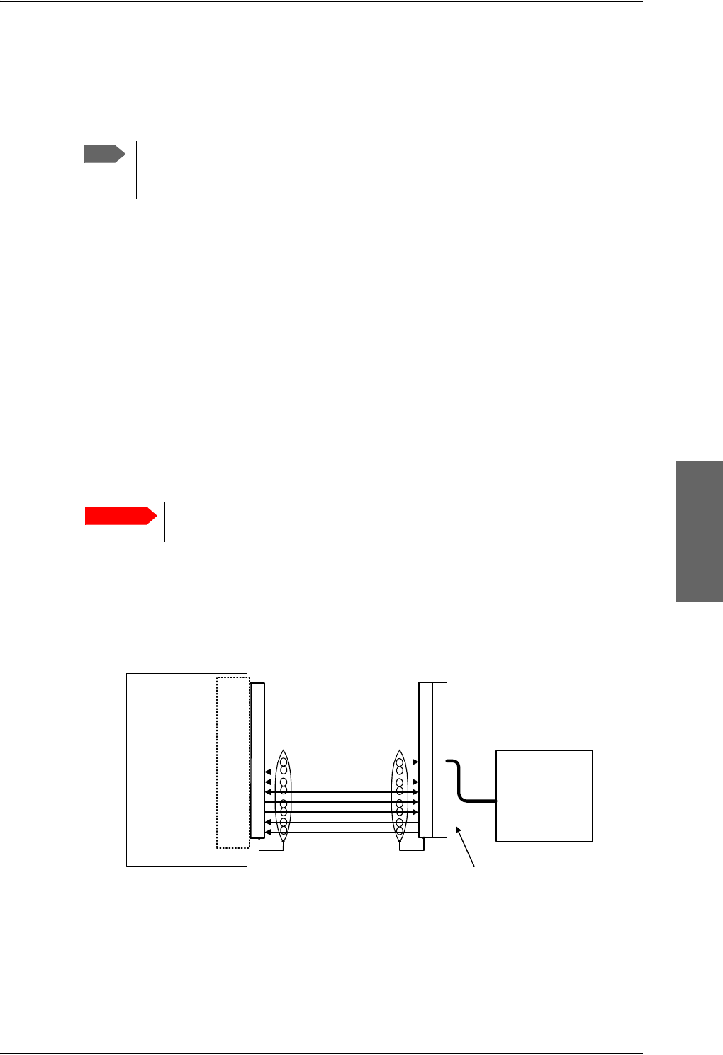
Electrical installation and wiring
98-124743-F Chapter 5: Installation 5-79
Reset
The SDU has a discrete input (BP77) on the rear connector, which can be used for SDU
hardware reset. The specification complies with the discrete WOW input.
SDU hardware reset is initiated by connecting the input to ground. This input is filtered
carefully, and the input must be activated for approximately 5 s before the reset procedure
takes action. It is highly recommended to use a guarded switch to avoid accidental
operation of the switch.
Electrical DC characteristics: WOW Input type, refer to Description of the discrete types on
page 5-68.
Pins for Automatic Test Equipment (ATE)
The ATE pins are for factory use only.The SDU and the SBU both have pins for Automatic
Test Equipment (ATE).
• SDU rear connector Bottom Plug (BP) pins: ATE 1 (BP74), ATE 2 (BP75) and ATE 3
(BP76).
• SBU rear connector Top Plug (TP) pins: ATE #1 (TP9) and ATE #2 (TP10).
Maintenance handset interface
The following drawing shows the wiring of the maintenance handset interface to the front
connector of the SDU.
Figure 5-36: Wiring maintenance handset
Note
You only need to connect this input if you have special requirements to the reset
function. For normal use, the push-button on the front panel of the SDU should be
sufficient.
Important
Do not connect anything to the ATE pins, not even ground! Connecting
the ATE pins can cause unintended function of the system.
77$
6'8
*1'3RZHU5HWXUQ
)3
)3
)3
)3
)3
)3
)3
)3
)URQW&RQQHFWRU
'%)
9'&P$
565;7;$
565;7;%
:LUH7HOHS/LQH7[
:LUH7HOHS/LQH5[
0DLQWHQDQFH
&UDGOH
77$
'%) '%0
'%0
1RWH7KH77$FUDGOHLVGHOLYHUHGZLWK
WKH'%0FRQQHFWRUPRXQWHGRQDSLJWDLO

Electrical installation and wiring
5-80 Chapter 5: Installation 98-124743-F
Pins for Maintenance handset interface
The following list shows the pins used for maintenance handset interface.
Description of the Maintenance handset interface
The SDU has a handset interface for the TT-5620A Handset for maintenance use.
This interface can be used to access the menu system using a 4-Wire Handset.
The front connector provides +12 V DC handset power (FP8). The RS-485 bus on the front
connector is common with the RS-485 bus for Handset #4 on the rear connector. The
Maintenance handset provides a common mode voltage (2.5 V DC) on the Audio In lines to
the SDU. This voltage is used to detect the presence of the handset on the front connector,
so the RS-485 #4 can be redirected to the front connector.
SDU Pin Function: Handset Interface
FP1 Maintenance Handset Audio In Hi
FP2 Maintenance Handset Audio In Lo
FP3 Maintenance Handset Audio Out Hi
FP4 Maintenance Handset Audio Out Lo
FP6 Maintenance Handset RS-485 Data A
FP7 Maintenance Handset RS-485 Data B
FP8 +12 V DC/120 mA
FP9 GND Power Return (for +12 V DC)
Table 5-58: SDU pins for Maintenance handset interface
Recommended cables
98-124743-F Chapter 5: Installation 5-81
5.4 Recommended cables
5.4.1 Introduction
This section lists recommended cables and allowed cable lengths for the cables in the
AVIATOR 700 system.
5.4.2 Power cables, allowed cable lengths
Allowed cable lengths, SDU
The following table shows the allowed SDU cable lengths for selected AWG types. If other
AWG types are used, make sure the contact type supports the AWG type.
It is generally recommended to keep cable lengths as short as possible, specially
on cables for Chassis GND.
Important
For specific requirements to the cables, see the applicable section in
5.3 Electrical installation and wiring.
Note
Description Pin Contact
Type Max. resistance Max Length (at 70C)
AWG20 AWG18 AWG16 AWG14
SDU
+28 V DC
Power
TP1 16 87.5 m a
(200 m-112.5 m
in circuit breaker)
a. The max. cable resistance is calculated using the resistance of a Klixon 2TC circuit breaker. If another circuit
breaker is used, the max. resistance and cable length may differ from these values.
7 fta
(2.1 m)
11 fta
(3.4 m)
18 fta
(5.4 m)
(not suitable
for this
contact size)
SDU
GND, Power
Return
TP2 16 25 m2 ft
(0.6 m)
3 ft
(0.9 m)
5 ft
(1.5 m)
(not suitable
for this
contact size)
SDU Chassis
Ground
TP3 16 25 m
(additional
requirement:
max. length 1 m)
2 ft
(0.6 m)
3 ft
(0.9 m)
3 ft
(1.0 m)
(not suitable
for this
contact size)
Table 5-59: Allowed lengths for SDU power cables
Recommended cables
5-82 Chapter 5: Installation 98-124743-F
Allowed cable lengths, HPA
The following table shows the allowed HPA cable lengths for selected AWG types. If other
AWG types are used, make sure the contact type supports the AWG type.
It is generally recommended to keep cable lengths as short as possible, specially
on cables for Chassis.
Note
Description Pin Contact
Type Max. resistance Max Length (at 70C)
AWG12 AWG10 AWG8
HPA
+28 V DC
Power
BP A1 5 87.5 m a
(100 m-12.5 m
in circuit breaker)
a. The max. cable resistance is calculated using the resistance of a Klixon 2TC circuit breaker. If
another circuit breaker is used, the max. resistance and cable length may differ from these
values.
(not suitable
for this
contact type)
71 fta
(21.6 m)
126 fta
(38.4 m)
HPA
GND, Power
Return
BP A2525 m(not suitable
for this
contact type)
20 ft
(6.1 m)
36 ft
(11.0 m)
Table 5-60: Allowed lengths for HPA power cables
Description Pin Contact
Type Max. resistance Max Length (at 70C)
AWG20 AWG18
HPA Chassis BP30 20HD 25 m2 ft
(0.6 m)
(not suitable for
this contact size)
Table 5-61: Allowed lengths for HPA chassis cable

Recommended cables
98-124743-F Chapter 5: Installation 5-83
Allowed cable lengths, SBU
The following table shows the allowed SBU cable lengths for selected AWG types. If other
AWG types are used, make sure the contact type supports the AWG type.
It is generally recommended to keep cable lengths as short as possible, specially
on cables for Chassis GND.
5.4.3 Recommended Power cables
The cable types shall meet the following standards:
• M27500 for shielded wire.
• M22759 for single wire.
Note
Description Pin Contact
type Max. resistance Max length (at 70C)
AWG20 AWG18 AWG16 AWG14
SBU
+28 V DC
Power
TP1 16 210 m a
(250 m-40 m in
7.5 A circuit
breaker)
a. The max. cable resistance is calculated using the resistance of a Klixon 2TC circuit breaker. If another circuit
breaker is used, the max. resistance and cable length may differ from these values.
17 fta
(5.2 m)
27 fta
(8.3 m)
43 fta
(13.2 m)
(not suitable
for this
contact size)
SBU
+28 V DC
Power
TP1 16 137.5 ma
(250 m-112.5 m
in 4 A circuit
breaker)
11 fta
(3.4 m)
18 fta
(5.5 m)
28 fta
(8.5 m)
(not suitable
for this
contact size)
SBU
GND, Power
Return
TP2 16 25 m
The cable should be
as short as possible,
max. 1 m.
2 ft
(0.6 m)
3 ft
(0.9 m)
5 ft
(1.5 m)
(not suitable
for this
contact size)
SBU Chassis
Ground
BP3 16 25 m
Connect directly to
aircraft chassis.
2 ft
(0.6 m)
3 ft
(0.9 m)
3.3 ft
(1.0 m)
(not suitable
for this
contact size)
Table 5-62: Allowed lengths for SBU power cables
Recommended cables
5-84 Chapter 5: Installation 98-124743-F
5.4.4 Recommended RF cables
The following cable types are recommended for the RF cables. Contact your cable supplier
for other cable types.
Equivalent cable types, which meet the requirements, may also be used.
Maximum cable lengths for WLAN cables
Note
CABLE TYPE SPECIFICATIONS
Part number Diameter
(mm/in.)
Minimum Bend
Radius (mm/ in.)
Attenuation
(dB/100ft)
@ 1.6 GHz
Size 5
contact part
number
ECS 3C142B 4.95/0.19 25.4/1.0 18.1 620021
PIC S22089 11.0/0.43 63.5 / 2.5 4.8 n.a.
PIC S33141 6.9/0.27 35.6 / 1.4 8.6 n.a.
ECS 310801 11.48/0.452 57.4 / 2.26 4.6 n.a.
ECS 311201 8.05/0.317 40.6 / 1.6 6.7 n.a.
ECS 311501 5.82/0.229 30.5 / 1.2 9.1 P922
EMTEQ TFLX165-100 4.19/0.17 21.6 / 0.85 16.8 A45165-1
EMTEQ PFLX195-500 5.08/0.2 12.7/0.5 14.0 A45195-1
EMTEQ TFLX295-100 7.95/0.31 40.6 / 1.6 7.6 n.a.
EMTEQ TFLX480-100 12.2/0.48 57.2 / 2.25 4.8 n.a.
Table 5-63: List of Recommended RF Cables
Cable from SBU to WLAN antenna W5 and W6 a
Part number
Cable
diameter
(mm/in.)
Attenuation
(dB/100 ft)
Maximum
cable
length
Size 5
contact
part number
RF specification @2.4 GHz: 5 dB
PIC S22089 11.0/0.43 6.7 dB 75 ft (23 m) n.a.
PIC S33141 6.9/0.27 11.0 dB 46 ft (14 m) n.a.
ECS 3C142B 4.95/0.19 22.2 dB 22 ft (6 m) 620021
ECS 310801 11.48/0.452 6.5 dB 75 ft (23 m) n.a.
ECS 311201 8.05/0.317 8.9 dB 56 ft (17 m) n.a.
Table 5-64: Allowed lengths for WLAN cables

Recommended cables
98-124743-F Chapter 5: Installation 5-85
5.4.5 Recommended cables for ARINC 429
Use ARINC 429 cables that meet the following standard:
• M27500 for shielded wire
The cables for the ARINC 429 interfaces must be twisted and shielded and conform to the
standards for aeronautical use.
5.4.6 Recommended cables for RS-422 SBU control interface
The interface is designed to be terminated with the characteristic impedance of the twisted
shielded cable: M27500-22SB2T23 from RAYCHEM.
5.4.7 Recommended cables for Ethernet
Cables for Ethernet on SBU (Quadrax connectors)
Use an Ethernet cable that meets one of the following standards:
• TIA/EIA568-A CAT5 Requirements
• FAR 25.869(a)
The following cable types meet the requirements:
• Part number: 422404, Quadrax 24 Awg from ECS
• Part number: F 4704-4 from Draka Fileca
5.4.8 Cables for Discrete Signals
Use cables for discrete wiring that meet the following standard:
• M27500 for shielded wire
ECS 311501 5.82/0.229 10.7 dB 46 ft (14 m) P922
EMTEQ PFLX195-500 5.08/0.2 16.81 30 ft (9 m) A45195-1
EMTEQ TFLX165 100 4.19/0.17 21.16 dB 23 ft (7 m) A45165-1
EMTEQ TFLX295 100 7.95/0.31 9.8 dB 52 ft (16 m) n.a.
EMTEQ TFLX480 100 12.2/0.48 5.8 dB 85 ft (26 m) n.a.
a. W5 and W6 stand for the cables needed when wiring the TT-5040A SBU, see Wiring
WLAN antenna interface on page 5-43.
Cable from SBU to WLAN antenna W5 and W6 a
Part number
Cable
diameter
(mm/in.)
Attenuation
(dB/100 ft)
Maximum
cable
length
Size 5
contact
part number
Table 5-64: Allowed lengths for WLAN cables (Continued)

Verifying the installation
5-86 Chapter 5: Installation 98-124743-F
5.5 Verifying the installation
Certain check procedures must be performed during and after installation of the AVIATOR
700 system. The first check procedures are performed after wiring, but before inserting
LRUs.For information on the required and recommended check procedures, see Check
procedures on page 7-1.
5.6 Activation of airtime services
Before the AVIATOR 700 system becomes operational, the aircraft owner or operator must
settle a contract with an Inmarsat Service Provider (ISP) so the system can be activated.
The airtime provider handles terminal activation, billing and technical support that is related
to the communication network.
The activation process may take some time, so to make sure it is ready in time, start the
activation procedure some time before the installation on the aircraft begins.
5.6.1 The 3 ID numbers for the AVIATOR 700 system
The AVIATOR 700 system is a hybrid system with 3 individual parts. Each part uses
different Inmarsat services and therefore has its own ID number in the Inmarsat network.
Table 5-65: ID numbers in the Inmarsat network
Service name ID Format
(example) Obtained from
Classic Aero (H+) ICAO aka AES ID 52535714 CAA or tail number
SwiftBroadband IMSI 123456789009876 SBU CM label or
Dashboard
Swift64 ISN 76TT12AABBCC SDU CM label or
Aero-SDU
Configuration
Program
ICAO address
The ICAO address (International Civil Aviation Organization) is a unique 24-bit number
assigned to an aircraft by the civil aviation authority of the state in which the aircraft is
registered. This number is the same number used for the Mode S transponder and the TCAS
system and in some countries it's calculated from the tail no.
In the Inmarsat world, this is also referred to as the AES ID (Airborne Earth Station ID). The
ICAO is normally noted in Oct (octal), but in some cases Hex is also used.
• Enter the aircraft's ICAO number in the Aero-SDU Configuration Program.
• Strap pins BP1-25 according to the ICAO. For further guidelines see Wiring ICAO
address on page 5-37.

Activation of airtime services
98-124743-F Chapter 5: Installation 5-87
ISN
The Inmarsat Serial Number (ISN) is the ID of the Swift64 part of AVIATOR 700. It has a
format like 76TT12AABBCC, where 76TT12 indicates a Cobham SATCOM Swift64 system
and the AABBCC is the actual 24 bit ID, also called forward ID. The ISN is pre-assigned to
the system by Cobham SATCOM and is printed on the label of the SDU configuration
module (CM). Note the CM has 2 ISN. Make sure to use the one marked SDU ISN for
AVIATOR 700. The ISN can also be seen in the Aero-SDU Configuration Program under the
Commissioning IDs.
IMSI
The IMSI (International Mobile Subscriber Identity) is the ID for the SwiftBroadband
service and is tied to the SBU Configuration Module (CM). The IMSI can be found either on
the label on the SBU CM or on the Dashboard of the SBU web interface.
Other Classic Aero numbers
The contract for classic aero services with your airtime provider contains among other
items the following phone numbers and identifiers:
• IMN (Inmarsat Mobile Number) on Swift64
• DDI (Direct Dial-In) on Aero H+
• Direct phone number to call the AVIATOR 700 system from the ground without
specifying the satellite region the terminal is located in (this is supported by a few
providers).
SwiftBroadband
The AVIATOR 700 system is delivered with the SIM card permanently installed in the CM of
the SBU, but not activated. The SIM card is pre-authenticated by Inmarsat and identified by
its unique IMSI number (International Mobile Subscriber Identity). The IMSI is usually 15
digits long.
The IMSI number is printed on the part number label of the CM. It is also printed
on the Certificate of Conformity letter belonging to the CM.
You need the IMSI to activate the Satellite communication service.
For details how to activate the SIM card please contact your airtime Provider.
The contract for SwiftBroadband services with your airtime provider contains among other
items the following phone numbers and identifiers:
• Direct phone number that is associated with the IMSI number of the installation.
Typically the service provider provisions the SIM card automatically to open up for the
circuit-switched and packet switched services.
To use the packet switched services you may have to enter the APN (Access Point
Name), make sure that you have received this information from your service
provider.
For step-by-step instructions how to enter the APN see Set the common interface
settings of the SBU on page 6-37.
Note
Note

Activation of airtime services
5-88 Chapter 5: Installation 98-124743-F
Making calls and using the Internet
For information on how to make a call to and from the system or go on the Internet etc. see
the User Manual.
Service providers
You find a list of Service providers on Inmarsat’s web site, Partner search
(http://www.inmarsat.com/partners/search-for-partner/).
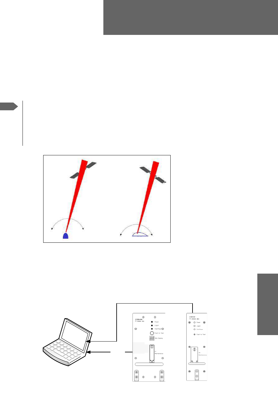
98-124743-F 6-1
Chapter 6
Configure the AVIATOR 700 system 6
6.1 Configure the basic system
To configure the AVIATOR 700 system you use the Aero-SDU Configuration Program for
the SDU and the Built-in web interface for the SBU.
Figure 6-2: Configuration tools for SDU and SBU
For quick start instructions see:
•Basic configuration of the SDU on page 6-9
•Basic configuration of the SBU on page 6-12
Note
Line of sight during operation
You can configure the system while the aircraft is in the hangar. Note that you
cannot typically check the satellite communication while the aircraft is still in the
hangar. There must be a line of sight between the Satcom antenna and the
satellite in order to use the satellite service.
Figure 6-1: Line of sight when communicating with the satellite
Satcom Antenna
3&ZLWKFRQILJXUDWLRQSURJUDP
DQGZHEEURZVHU
56
/$1FDEOH
&RQILJXUDWLRQ
SURJUDPIRU
6'8
:HE
LQWHUIDFH
IRU6%8

Aero-SDU Configuration Program for the SDU
6-2 Chapter 6: Configure the AVIATOR 700 system 98-124743-F
6.2 Aero-SDU Configuration Program for the SDU
Configuration parameters for the SDU are stored in the SDU Configuration Module (CM),
which is managed from the Aero-SDU Configuration Program for the MS Windows®
operating systems.
The Aero-SDU Configuration Program makes it possible to:
• Read, write and edit a complete set of operating parameters for the SDU system
• Show which units are available
• Set up the SDU and cabling with all configurable parameters
• Access the SBU configuration tool (web interface)
• Save/load an SDU configuration to/from a file
• Print reports to a printer
•Update the SDU and HPA software
• Access a terminal emulator for troubleshooting purposes
• Acquire elevation and azimuth for I3 and I4 satellites for any geographical location
• Get online help on specific topics through the Help menu, by pressing F1, or by using the
“What’s This?” button
6.2.1 Install the Aero-SDU Configuration Program
Installation requirements
• Installation CD (included in the delivery of the AVIATOR 700 system). You can also
download the Aero-SDU Configuration Program at
https://sync.cobham.com/satcom/support/downloads or
http://www.cobham.com/cobham-satcom-service-and-support for non-partners.
• A PC running Windows Vista, Windows 7, Windows 8 or Windows 10.
• 1024×768 or higher display resolution. The program is best viewed using small fonts.
• Data Cable (Part number TT 37-112940-A or equivalent) to connect a PC to the SDU.
• An available serial COM port (DB9) for the Data Cable.
• Ethernet cable (straight)
Installation procedure
Insert the CD-ROM with the Aero-SDU Configuration Program into the CD ROM drive and
wait until the PC automatically starts the installation program (if the installation program
does not start automatically, open the file-explorer and double-click the file named
setup.exe).
Go through the InstallShield Wizard. When installation is done, a shortcut is placed on your
desktop.
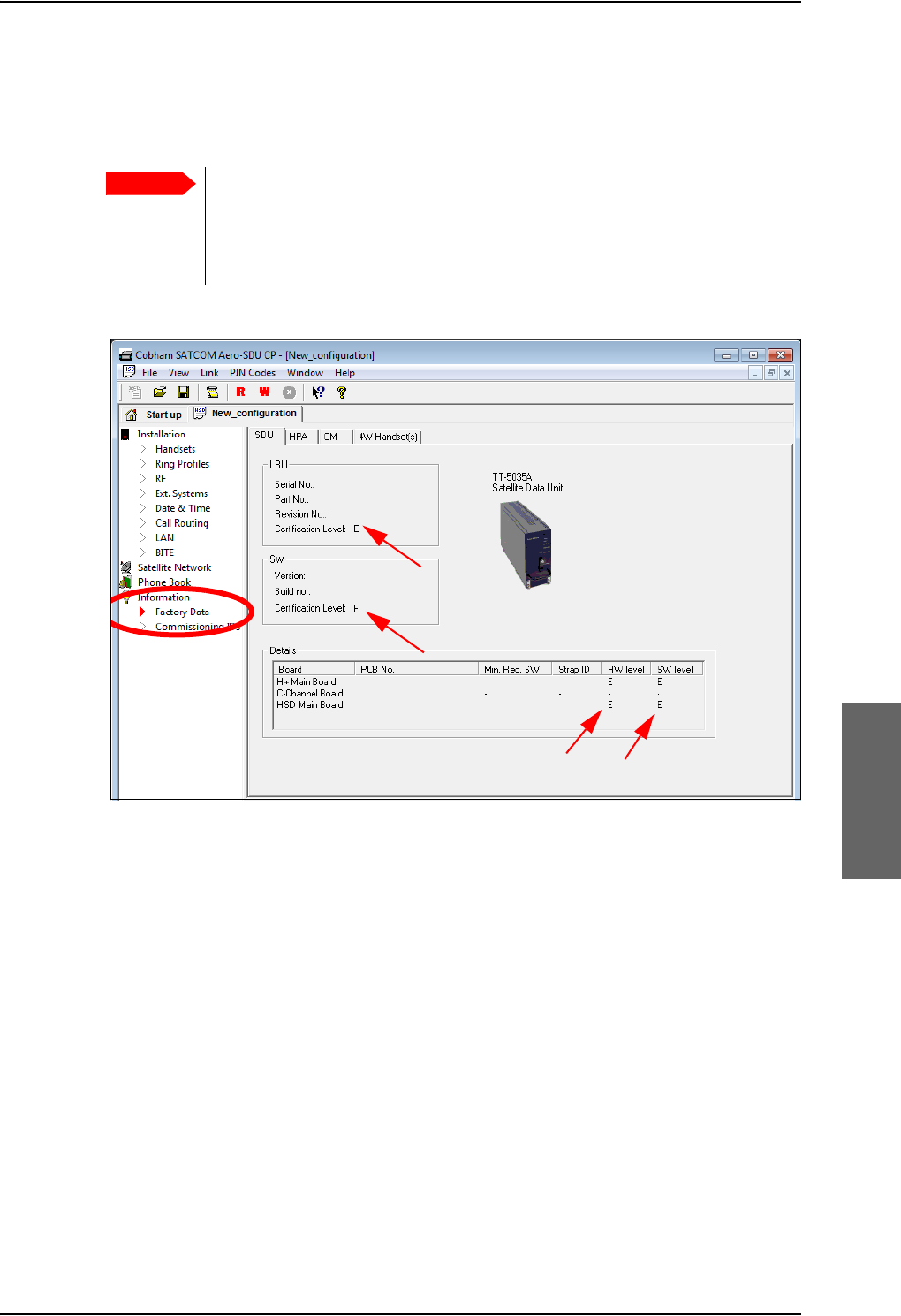
Aero-SDU Configuration Program for the SDU
98-124743-F Chapter 6: Configure the AVIATOR 700 system 6-3
6.2.2 To use the Aero-SDU Configuration Program
The Aero-SDU Configuration Program is used to configure both AVIATOR 700 and Aero-
HSD+systems.
No mismatch for Level D and Level E allowed: If a level-D certified
system detects an inconsistent hardware unit (level E) or software image
(level E), it enters failure mode and the system will not be operational.
Inconsistency messages are displayed to clearly inform the service personnel
about the reason for this failure mode.
Figure 6-3: Aero-SDU Configuration Program: View Level D and Level E certification level
Important
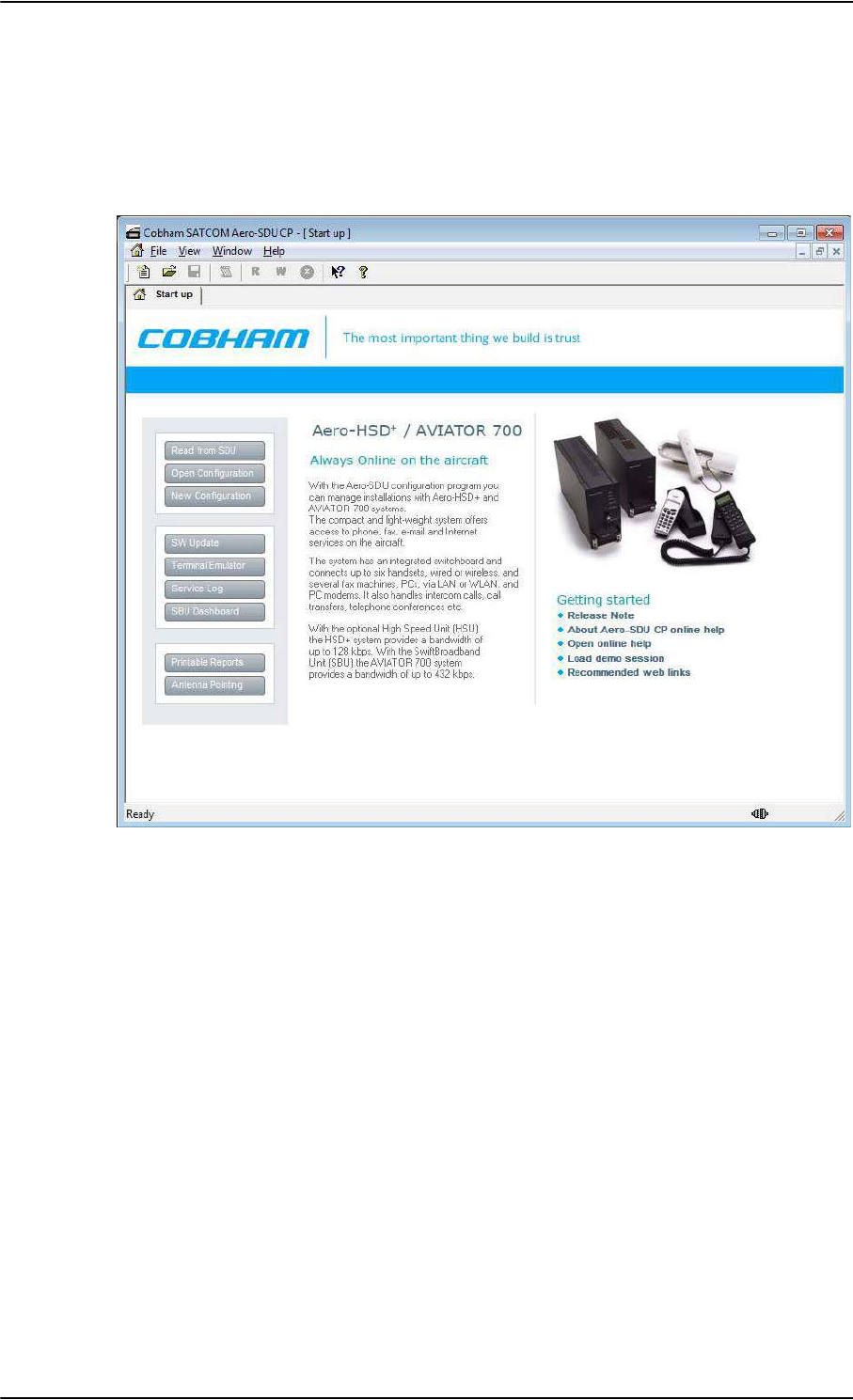
Aero-SDU Configuration Program for the SDU
6-4 Chapter 6: Configure the AVIATOR 700 system 98-124743-F
Start the Aero-SDU Configuration Program
To start up the Aero-SDU Configuration Program, double-click the program icon on your
desktop.
The following picture shows the start up window of the configuration program.
You can perform several tasks from the start up window. This chapter concentrates on the
configuration task.
Figure 6-4: Aero-SDU Configuration Program: Start-up window
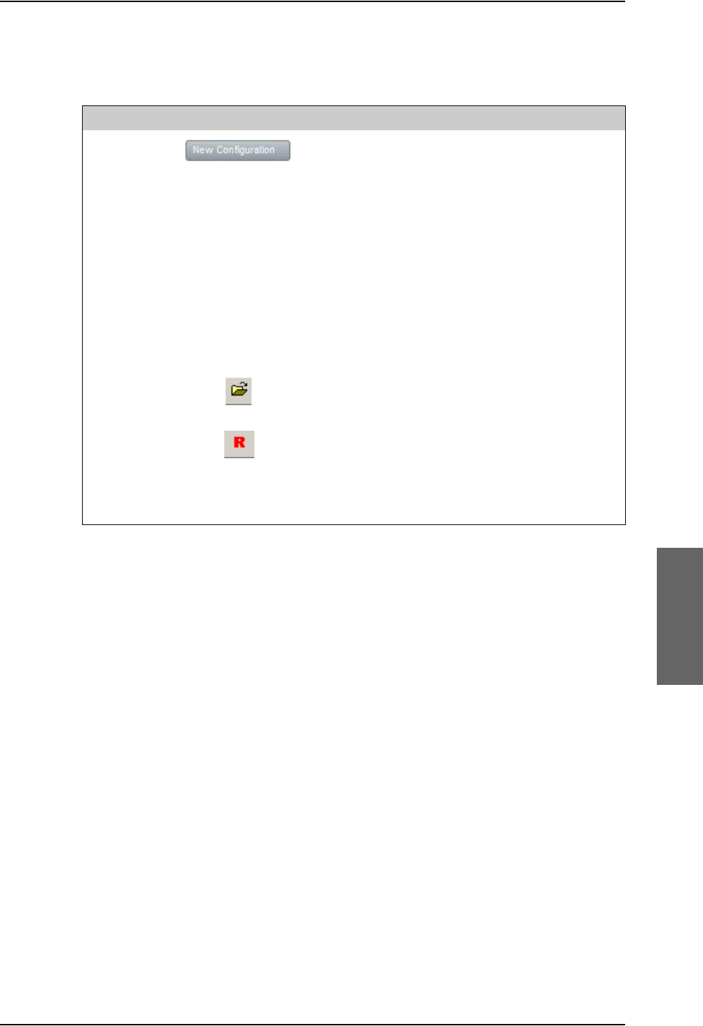
Aero-SDU Configuration Program for the SDU
98-124743-F Chapter 6: Configure the AVIATOR 700 system 6-5
Navigation
The most important menu commands to start managing a configuration are:
Table 6-1: Configuration related menu commands
File, New Create a new configuration from scratch (Only the
most critical parameters are initialized, the rest is up
to you).
Confirm the system to configure: AVIATOR 700
Up to four different configurations can be open at
the same time.
The configuration can be created off-line (i.e.
without an SDU connected to the PC). The settings
can then be written to the SDU at a later stage.
Note: Offline configuration can only be done for
the SDU. To configure the SBU you must be online.
File, Open Opens a previously saved configuration from the
disk.
File, Read
Configuration
from SDU
Read configuration from the connected SDU and
copy the data into a new configuration.
Note. This function is most suited for tasks that
involve minor modifications to already installed
systems.
Menu keys Icon or button Description
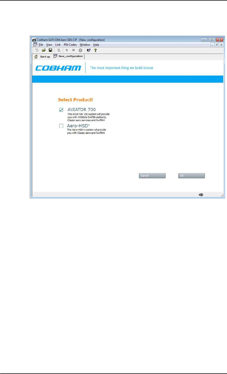
Aero-SDU Configuration Program for the SDU
6-6 Chapter 6: Configure the AVIATOR 700 system 98-124743-F
Having opened a new configuration, you are prompted to confirm the system you are
about to configure. Select AVIATOR 700 and click OK to continue.
Figure 6-5: Configuration program: System selection, Aero-SDU Configuration Program
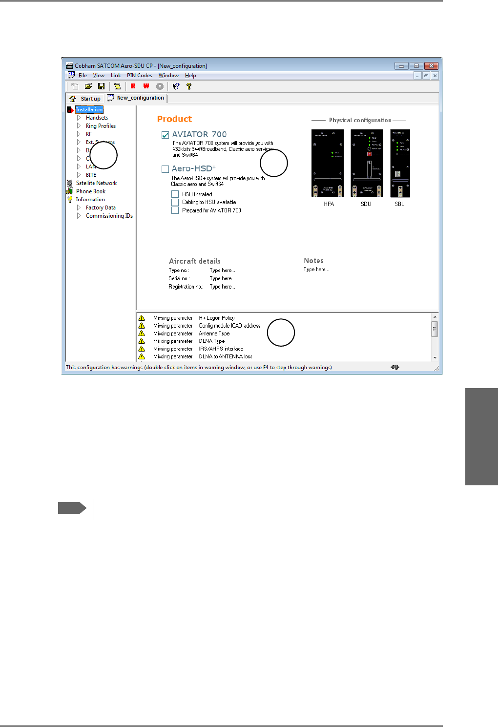
Aero-SDU Configuration Program for the SDU
98-124743-F Chapter 6: Configure the AVIATOR 700 system 6-7
When one of the products is selected, the configuration view opens.
Figure 6-6: Aero-SDU Configuration Program, configuration view
The configuration view is divided into three panes:
1. Navigation pane to access specific sections of the configuration
2. Settings pane to set individual configuration settings
3. Warnings pane listing the tasks to set up a valid configuration, and displaying errors and
notes.
Menus in the Navigation pane
The Aero-SDU Configuration Program comprises the following items:
Installation - aircraft details and installed units.
•Handsets - setting of handset type, volume, ring tones etc. Fax connected to 2-wire.
•Ring Profiles - setup of ring profiles that each determine the behavior of all
handsets and annunciators.
•RF - setup of antenna and DLNA types, antenna heading, SBU unit installed and RF
cable losses.
Note
For instructions how to make a software update see Software update on page 8-8.
1
2
3
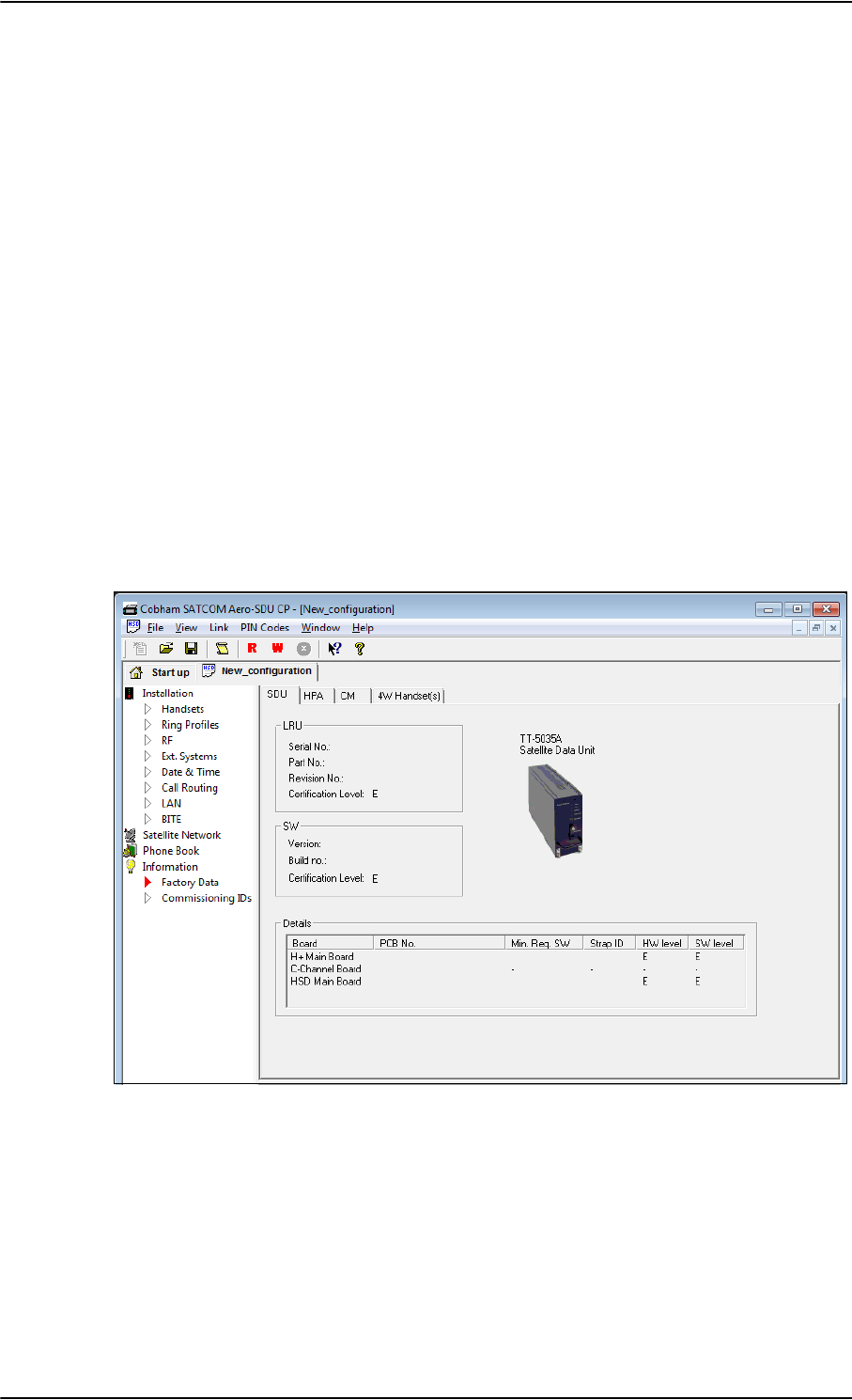
Aero-SDU Configuration Program for the SDU
6-8 Chapter 6: Configure the AVIATOR 700 system 98-124743-F
•Ext. Systems - setup of external systems such as IRS/AHRS, ACARS/AFIS/CMU,
MCDU etc.
•Date & Time - setup of date and time in the SDU and synchronization.
•Call Routing - setup of how the SDU should behave to incoming and outgoing calls.
•LAN - IP parameters for LAN connection. Under normal conditions, these parameters
should not be changed.
•BITE - List of BITE codes with the option to disable display of selected codes.
Satellite Network - setup of the conditions for logon to the satellite network,
including automatic/manual logon, setup of GES for the H+ service and LES for the
Swift64 service and initial satellite data.
Phone Book - a list of up to 99 phone numbers. From this window you can add, edit
and delete information in the phone book and assign quick-dial numbers.
Information
•Factory data - showing the version of the software installed in the SDU, including
the certification level D or E, the PCB numbers of the individual boards in the system,
the serial numbers of the LRUs in the system, the LRU revision numbers of the: SDU,
CM, HPA, 4W Handset(s) units.
•Commissioning IDs - setup of ICAO address and inspection of ISN numbers.
Settings pane
This pane contains the details related to the items you can select in the Navigation pane.
Figure 6-7: SDU configuration, Information> Factory Data: View the certification level

Aero-SDU Configuration Program for the SDU
98-124743-F Chapter 6: Configure the AVIATOR 700 system 6-9
Warnings pane and SDU configuration guide
This pane contains a list that can hold a mix of: A list of the parameters that need to be
entered, errors and notes. The list serves two main purposes:
1. Configuration guide: To show what you need to change/set up before the
configuration can be written to the SDU. If something important remains in this list
when the write to SDU function is applied an error dialog appears.
When you have configured the system correctly, this warnings pane will be empty.
2. Warnings and notes: To indicate where your configuration differs from what Cobham
SATCOM recommends (ex. antenna gain exceeds expected limits).
Note: Double click on the items in the list one by one to work through the necessary
configuration settings. A click on an item brings you directly to the hot spots in the
configuration that need your attention.
6.2.3 Basic configuration of the SDU
For detailed information on how to use the Aero-SDU Configuration Program, please refer
to the built-in help system of the program. Press F1 or use the Help menu.
As a minimum setup, you need to set up the following parameters:
Commissioning ID
•ICAO address.
In the navigation pane of the Aero-SDU Configuration Program, select Commissioning
IDs under Information. Then click the Copy button to copy the strapped ICAO
address to the Config Module, or type in the ICAO address in the Config Module field.
RF settings SDU
•Antenna type and heading offset.
Select RF under Installation and select the antenna type.
•DLNA type.
In the RF pane select the DLNA type.
•Cable loss for SDU.
In the RF pane, enter the cable losses in the Cable Loss fields. These cable loss values
are without losses from the RX splitter and TX combiner.
The necessary RF settings for the SBU are described in Basic configuration of the SBU on
page 6-12.
External systems
•Navigation parameters, IRS/AHRS.
Select Ext. Systems under Installation.
Then select IRS or AHRS, select which interfaces are connected and whether they run at
low or high speed.

Aero-SDU Configuration Program for the SDU
6-10 Chapter 6: Configure the AVIATOR 700 system 98-124743-F
Satellite network
•Preferred GES
Select Satellite Network and set up the list of preferred GES.
•Preferred LES and Logon Policy
Set up the list of preferred LESs.
Set H+ Logon Policy to Automatic or Manual.
Enable handsets
•Handset parameters, Broadcast Ring Tone.
Select Handsets under installation. Then select a ring tone from the Broadcast Ring
Tone scroll list.
External equipment
Depending on the connected equipment, it may be necessary to enter information on
some of the following items:
•Handsets.
Select Handsets under Installation.
Then enter which handset is installed on which interface and set the parameters for each
handset.
• For handset interface #1 and #2 you may select T&T Handset, MagnaStar, WH10,
Cockpit Audio, Iridium-1, Iridium-2 or FONE.
•For handset interface #3 you may select T&T Handset, MagnaStar, WH10, Iridium-1,
Iridium-2 or FONE.
• For handset interface #4 only T&T handset is available.
• For handset interface #5 and #6 you may select Handset, Fax or ICG Handset (for
Sigma7 handset).
•Fax.
In the Handsets pane, select the Fax handset-type under Two-Wire POTS #5 or #6. This
means the interface will not ring on a broadcast call.
•Ring Profiles.
Select Ring Profiles under Installation. Set up one or more profiles that determine
which interfaces should ring when a broadcast call is received, and which should not.
There are five possible profiles. One of them, “TakeOfLandng”, is preset and cannot be
changed. If the “Chime/Lamps Inhibit” input is activated, the “TakeOfLandng” profile is
automatically used. This input should be activated during take-off and landing.
•ACARS/AFIS/CMU/MCDU/WOW.
Select Ext. Systems under Installation.
Then enter which systems are connected and enter the requested parameters for each
system.
Write the configuration to the SDU
To transfer the content of the active configuration view into the connected SDU click the
button in the top toolbar.
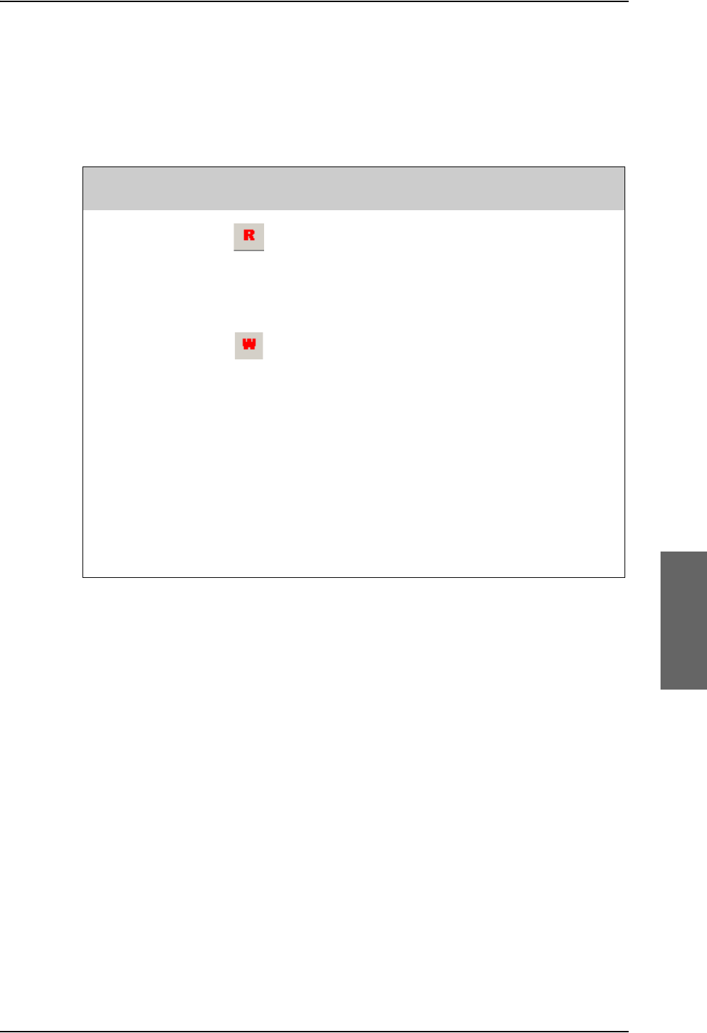
Aero-SDU Configuration Program for the SDU
98-124743-F Chapter 6: Configure the AVIATOR 700 system 6-11
6.2.4 Transfer configuration data to the SDU
You transfer configuration data to the SDU using the Aero-SDU Configuration Program.
Before transferring the settings, connect the TT37-112940-A data cable between the serial
port of the PC and the front connector of the SDU. Use the menu commands listed below
to select the direction of the transmission.
Table 6-2: Menu commands for configuration data transfer
Link - Read
configuration
from SDU
(Or use keyboard
shortcut Ctrl-R)
Transfer the configuration from the SDU connected
into the configuration view that is active right now.
Link - Write
configuration to
SDU
(Or use keyboard
shortcut Ctrl-W)
Transfer the content of the active configuration
view into the connected SDU.
1. Before writing the configuration, the
configuration program validates the data. If this
validation fails due to errors in the configuration, a
dialog will inform you about it, and the write
operation is cancelled. See also messages in the
warning pane for more information.
2. Before the write operation is started you will
have the choice to turn off reset-after-write. Please
note that settings are only applied to the system
after a reset. Under normal circumstances you do
not need to change this.
Select a COM port: The first time you try to communicate with the SDU, a popup dialog
will ask you to select a COM-port from a list of installed COM-ports. This dialog will also
appear if the SDU was not found on the selected COM-port.
Menu key
combination Icon Description
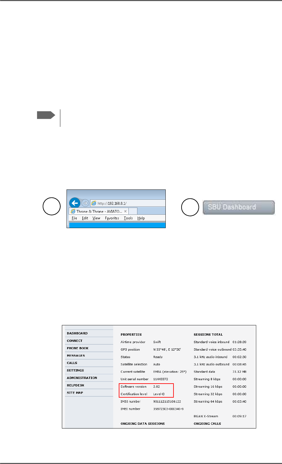
SBU Configuration tasks
6-12 Chapter 6: Configure the AVIATOR 700 system 98-124743-F
6.3 SBU Configuration tasks
Having installed the AVIATOR 700 System you must also configure the SwiftBroadband
Unit properly for use with the current antenna setup, including cable losses for the
installation, and select the correct navigational input. Furthermore the interfaces have to be
set up and configured to the specific aircraft installation and application requirements. IP
connections, network user groups and profiles for IP data usage including LAN/WLAN
network management must be configured so the required applications run smoothly on the
system. For this purpose you use the built-in web interface of the SBU.
There are two ways to access the SBU web interface:
1. Use a web browser and enter the IP address of the SBU. The standard IP address is
192.168.0.1.
2. Using the Aero-SDU Configuration Program, click on the button SBU Dashboard in
the left side of the startup window.
6.3.1 Basic configuration of the SBU
As a minimum, you need to set up the following parameters in the built-in web interface of
the SBU:
1. On the DASHBOARD verify that you have the latest SBU software version (see
cobham.com/satcom, Service and support). Verify also that the certification level is
correct (Level-D or Level-E). For more information on the individual fields see Use the
Dashboard on page 6-22.
Figure 6-9: Basic configuration of the SBU, step 1/6
Note
Before you start configuring the SBU make sure that the Configuration Module for
the SBU is mounted in the SwiftBroadband Unit.
Figure 6-8: 2 ways to access the SBU web interface
2
1
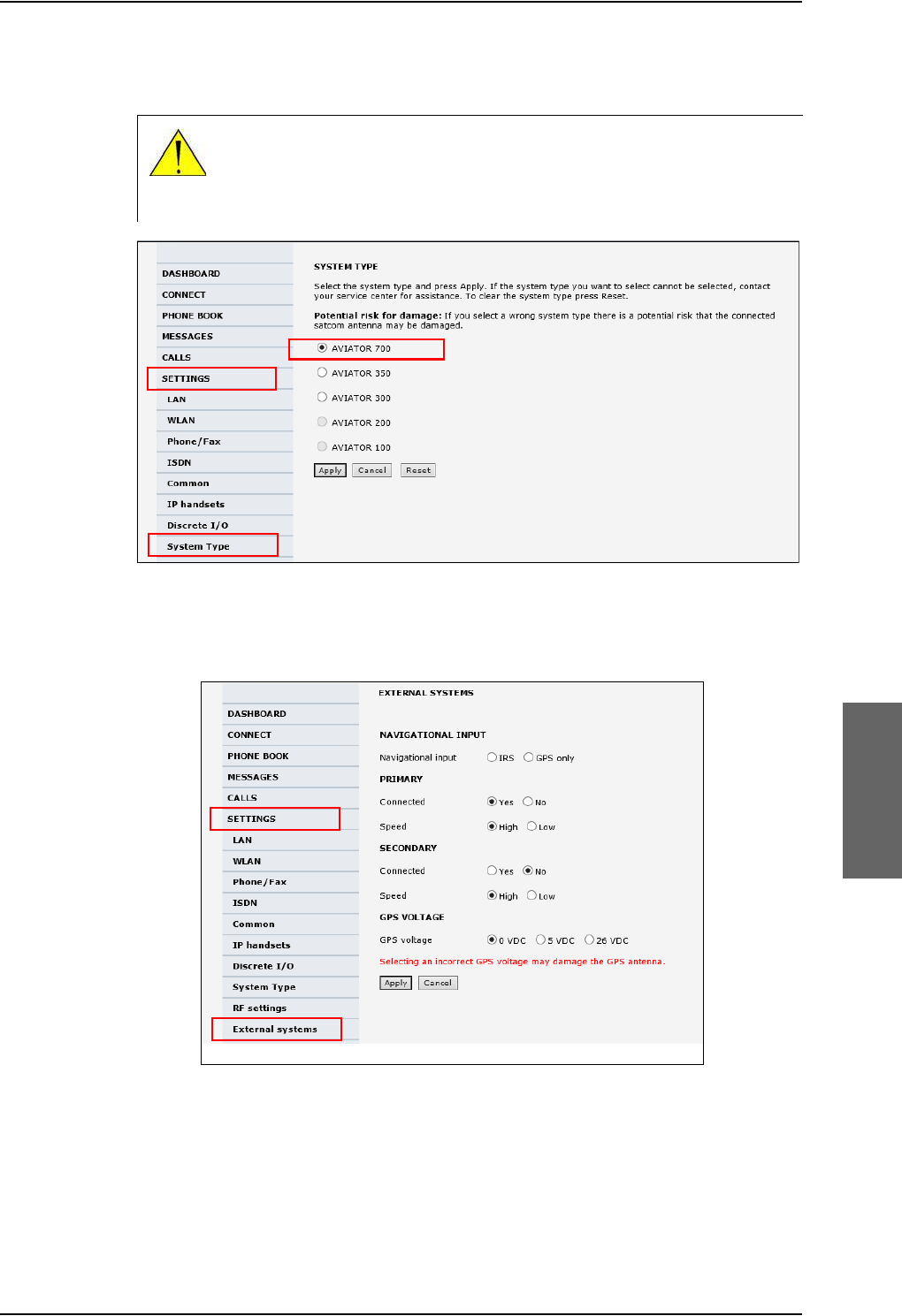
SBU Configuration tasks
98-124743-F Chapter 6: Configure the AVIATOR 700 system 6-13
2. In SETTINGS > System type, select AVIATOR 700 and click Apply.
Figure 6-10: Basic configuration of the SBU, step 2/6
3. In SETTINGS > External systems enter the values for Navigational input and GPS
voltage. For detailed instructions see Set up the navigational input of the SBU on
page 6-51.
Figure 6-12: Basic configuration of the SBU, step 3/6
CAUTION! Selecting a wrong system type may cause damage to the
satcom antenna or GPS antenna. If the system type purchased can not be
selected, please contact the supplier of your AVIATOR 700 system.
Do not try to use a different system type!
1
2
3
1
2
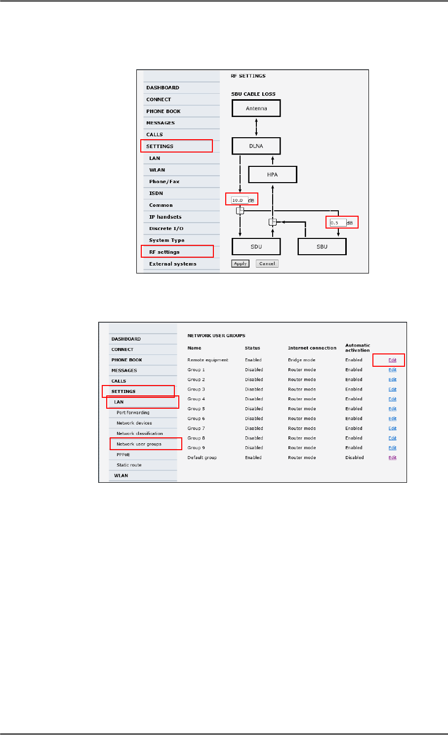
SBU Configuration tasks
6-14 Chapter 6: Configure the AVIATOR 700 system 98-124743-F
4. In SETTINGS > RF settings, enter the cable losses applicable to the SBU. For detailed
instructions see Configure RF settings of the SBU on page 6-50.
5. In SETTINGS > LAN > Network user groups, click Edit.
Figure 6-14: Basic configuration of the SBU, step 5/6
Figure 6-13: Basic configuration of the SBU, step 4/6
1
2
3
4
1
2
4
3
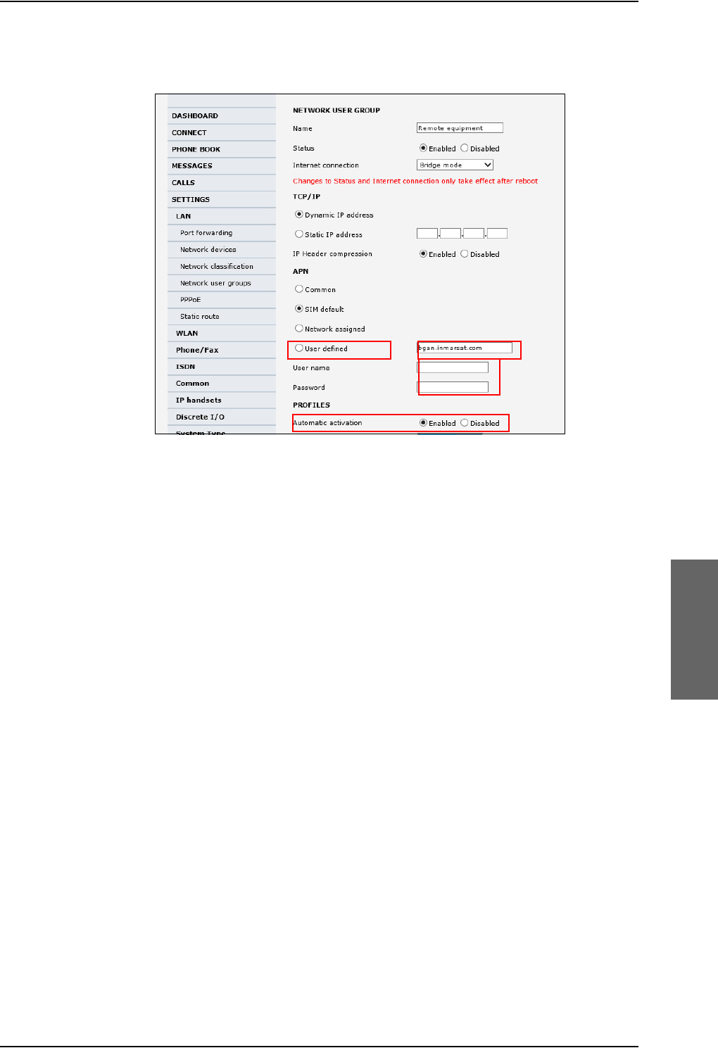

Built-in web interface for the SBU
6-16 Chapter 6: Configure the AVIATOR 700 system 98-124743-F
6.4 Built-in web interface for the SBU
Use the built-in web interface of the SBU to access the SBU configuration settings in the
CM of the SBU. A subset of the configuration settings are stored in a write-protected area
of the CM. This subset contains the physical settings for the antenna, cabling and other
external input.
To set up or change the settings of the write-protected area you must
connect a PC to the connector marked Maintenance on the SBU front plate.
You can view all SBU settings from any LAN or WLAN interface.
The CM also contains the SIM card for accessing the SwiftBroadband service. The settings
that can only be changed when connected to the SBU maintenance connector are:
•Discrete I/O settings
•System type
•Cable loss data in Settings, RF settings,
• Input from navigational systems in Settings, External systems
• Enabling options (Router, WLAN) in Settings, Flex.
No installation of software is necessary because the web interface is built into the SBU.
Browsers supported
The web interface is built into the terminal and is used for operating, setting up and
configuring the system.
You can access the web interface from a computer with a standard Internet browser.
Important
Note
For information on daily use of the AVIATOR 700 system refer to the AVIATOR
700 User Manual.
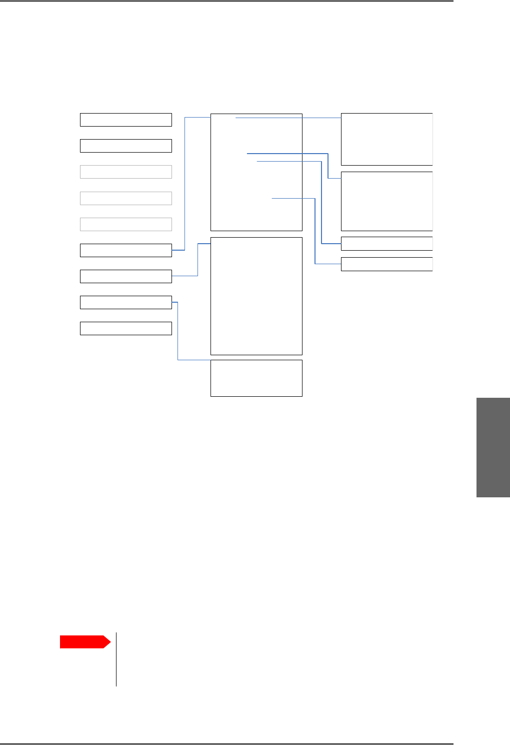
Built-in web interface for the SBU
98-124743-F Chapter 6: Configure the AVIATOR 700 system 6-17
6.4.1 Topics in the SBU web interface
The following drawing shows the topics available in the web interface. The topics in grey
are mainly used during daily use of the system, they are described in detail in the AVIATOR
700 User Manual.
Figure 6-16: Topics in the SBU web interface
6.4.2 Check the connection to the web interface
To check whether you can connect to the web interface of the SBU do as follows:
1. Power up the AVIATOR 700 system. Wait until the LEDs on the front plate show that the
system is ready to be configured.
•Power LED: Green, then wait for approximately one minute.
2. Connect a PC to the Maintenance interface (standard Ethernet) on the front plate of
the SBU.
If you want to change the setup of the user interfaces and change network usage you
can use any of the terminal LAN interfaces (up to 6) installed in the aircraft cabin or the
Wireless connection, if available. If you want to change the physical settings for the
antenna, cabling and other external input you must use the SBU maintenance
connector at the front of the SBU.
3RUWIRUZDUGLQJ
1HWZRUNGHYLFHV
1HWZRUNFODVVLILFDWLRQ
1HWZRUNXVHUJURXSV
333R(
6WDWLFURXWH
&DOOIRUZDUG
&DOOEDUULQJ
&DOOZDLWLQJ
/LQHLGHQWLILFDWLRQ
&ORVHGXVHUJURXS
/RFDOH[FKDQJH
/$1
:/$1
3KRQH)D[
,6'1
&RPPRQ
,3KDQGVHWV
'LVFUHWH,2
6\VWHPW\SH
5)VHWWLQJV
([WHUQDOV\VWHPV
)/(;
7UDFNLQJ
8SORDG
&DOOFKDUJHV
/RJKDQGOLQJ
'DWDOLPLWV
3URILOHV
7UDIILFIORZILOWHUV
6,03,1
6,0/RFN
8VHUSHUPLVVLRQV
5HPRWHPDQDJHPHQW
/LQNPRQLWRULQJ
5HPRWHDFWLYDWLRQ
5HVWULFWHGGLDOLQJ
0XOWLYRLFH
(YHQWOLVW
(YHQWORJ
([WHQGHGVWDWXV
6HOIWHVW
'$6+%2$5'
&211(&7
3+21(%22.
0(66$*(6
&$//6
6(77,1*6
$'0,1,675$7,21
+(/3'(6.
6,7(0$3
&DOOVHWWLQJV
&08$&$56
Important
For systems without the built-in router option enabled, i.e. the basic version or
the version with Wireless option only: To use the SBU Maintenance
connector disconnect or switch off any PC connected to another LAN
interface of the SBU.
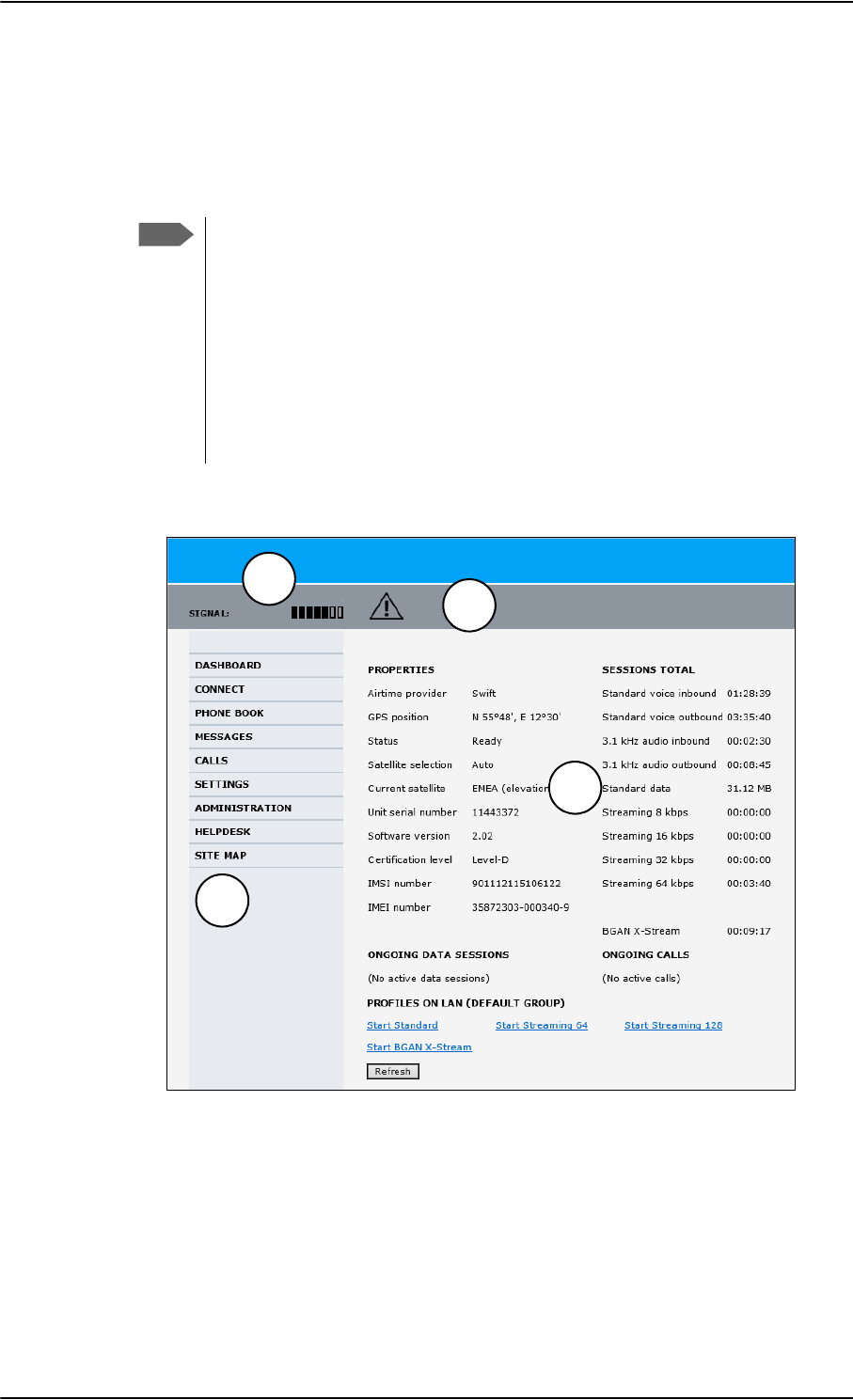
Built-in web interface for the SBU
6-18 Chapter 6: Configure the AVIATOR 700 system 98-124743-F
Access the web interface
To access the web interface, do as follows:
1. Open your browser and enter the IP address of the SBU. The standard IP address is
192.168.0.1.
If the local IP address of the SBU has been changed and you do not have the
new address, you can temporarily set the IP address to the default value by
pushing the Reset button on the front plate of the SBU. For detailed
instructions see How to reset the IP address or the terminal software to
default settings on page 8-23.
For further information on the Reset button, see IP Reset (Default) button on
the SBU on page 8-22.
For further information on IP addresses of the SBU see Set up the LAN IP
addressing on page 6-28.
2. The web interface opens directly with the DASHBOARD page.
The web interface consists of the following sections:
1. The navigation pane holds the main menu. Clicking an item in the menu opens a
submenu in the navigation pane or a new page in the contents section.
2. The signal status field shows the signal strength. The signal strength can vary during
operation, depending on the current position relative to the Inmarsat satellite and the
call or data session activity.
Note
Figure 6-17: Sections of the web interface
1
23
4
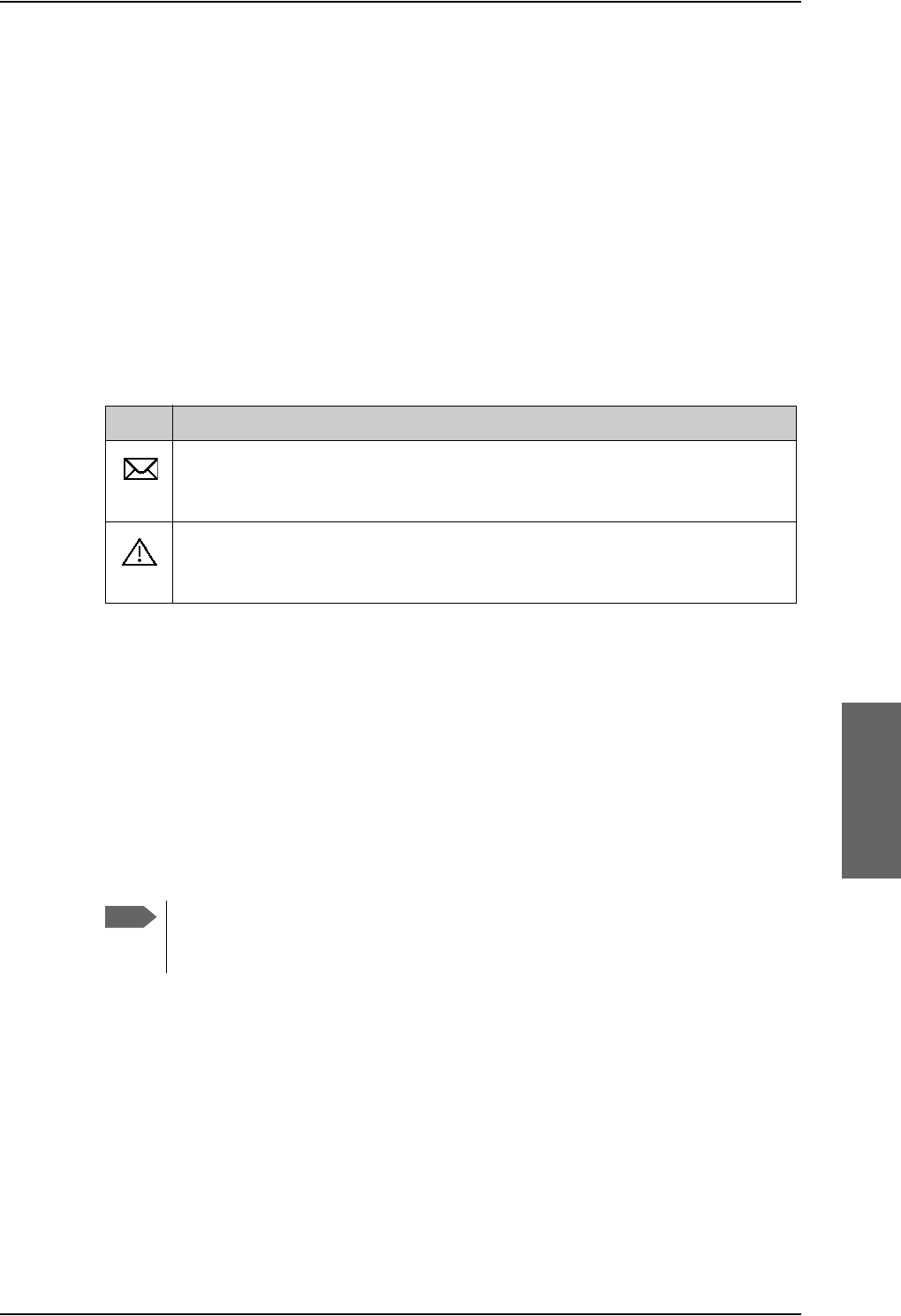
Built-in web interface for the SBU
98-124743-F Chapter 6: Configure the AVIATOR 700 system 6-19
3. The icon bar shows icons for new SMS messages and for active events, when relevant.
For explanations of the icons, see the next section, Icons in the icon bar.
4. The contents section shows the page selected in the navigation pane. This section is
used for viewing or changing settings, or for performing actions.
When the Dashboard is displayed you have verified that the connection to the SBU can be
established. The web interface is ready for use. You can continue to configure the system.
If you cannot establish a connection to the SBU there might be problems with the Proxy
server settings of your PC. See Proxy server settings in your browser on page 6-20 for
further information.
Icons in the icon bar
The following icons may appear in the icon bar in the web interface:
Navigate the web interface
•To expand a menu, click the menu in the navigation pane.
•To access status and settings, click the relevant subject in the navigation pane or
click the relevant icon in the icon bar. The status or settings are displayed in the contents
section.
•To get an overview over the submenus available use the site map, click SITE
MAP in the navigation pane. Click on items in the site map to go directly to the relevant
location.
Icon Explanation
A new SMS message, or information of Voice mail, has arrived. Click the icon to
see new messages or information of Voice mail. For further information, see the
AVIATOR 700 User Manual.
An event is active. Click the icon to see a list of active events. For explanations
of the event messages, see the AVIATOR 700 User Manual. Note that this icon
will remain in the icon bar as long as the event is still active.
Table 6-3: Web interface: Icons
Note
You can limit access to some parts of the web interface for certain users. Then the
parts are grayed out. For information on how to set up user permissions, see Set
up user permissions on page 6-84.
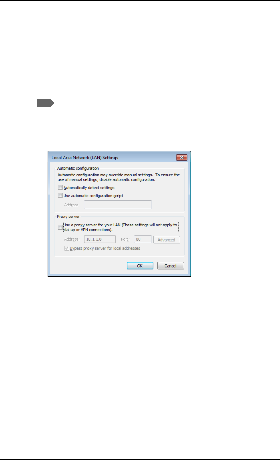
Built-in web interface for the SBU
6-20 Chapter 6: Configure the AVIATOR 700 system 98-124743-F
Proxy server settings in your browser
If you are connecting your computer using a LAN or WLAN interface, the Proxy server
settings in your browser must be disabled before accessing the web interface. Most
browsers support disabling of the Proxy server settings for one specific IP address, so you
can disable Proxy server settings for the web interface only, if you wish. Consult your
browser help for information.
To disable the use of a Proxy server completely, do as follows:
1. In Microsoft Internet Explorer, select Tools > Internet Options > Connections >
LAN Settings.
2. Clear the box labeled Use a proxy server for your LAN.
3. Click OK.
When the proxy server settings are disabled, close and restart your browser. You may need
to change this setting back on return to your Internet connection.
IP address and DNS server address setup
To check whether automatic IP address and DNS server address is obtained automatically
for your computer, do as follows (example for Windows 7):
1. Go to Control Panel > Network and Internet > Network and Sharing Center.
2. Click on the LAN connection you want to use.
3. Select Properties, highlight Internet Protocol Version 4 (TCP/IPv4).
4. Click Properties.
Note
The following description is for Microsoft Internet
Explorer. If you are using a different browser, the
procedure may be different.
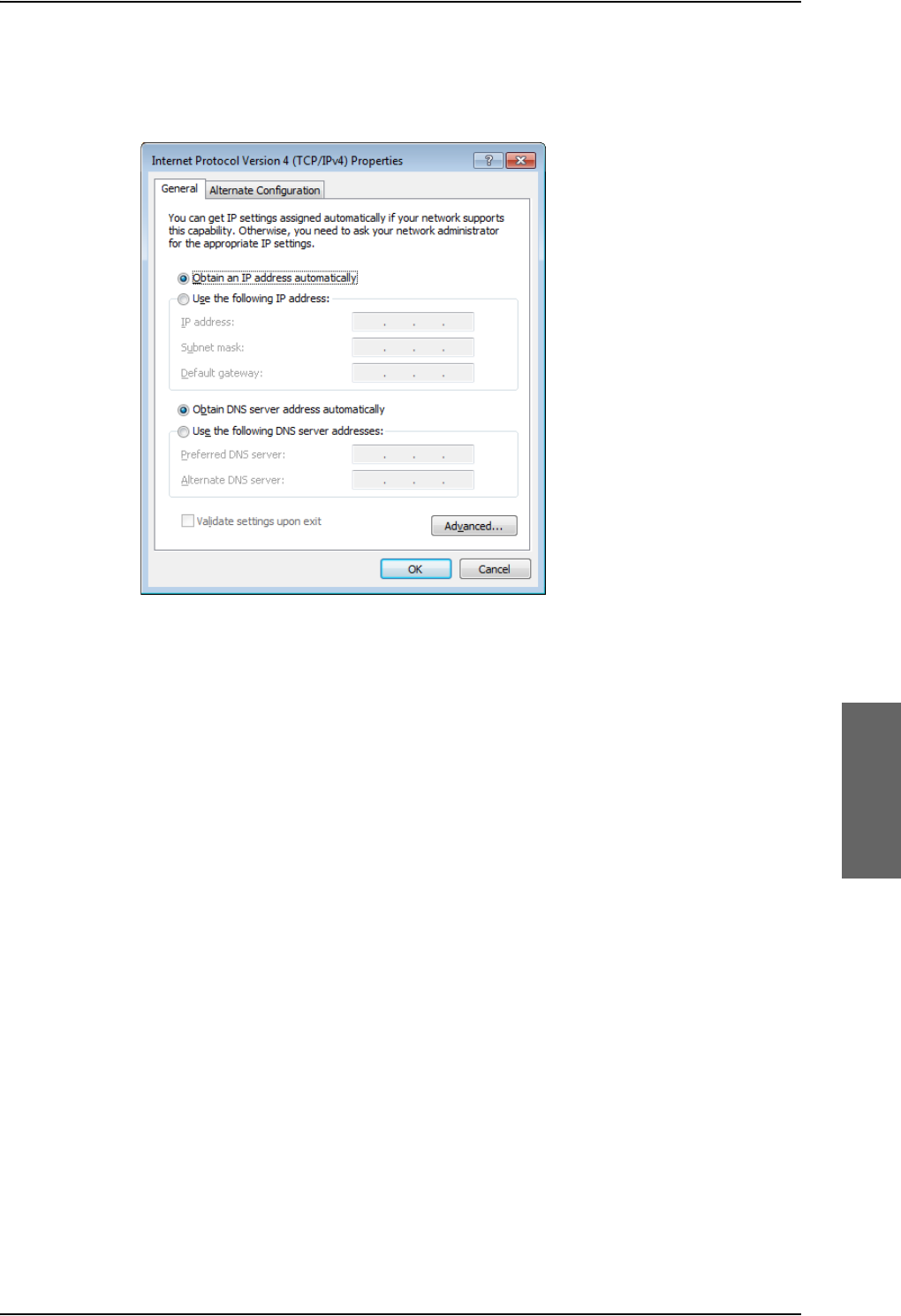
Built-in web interface for the SBU
98-124743-F Chapter 6: Configure the AVIATOR 700 system 6-21
5. Make sure that the following is selected:
- Obtain an IP address automatically
- Obtain DNS server address automatically
Allocating IP addresses and DNS server lookups are handled by the SBU.
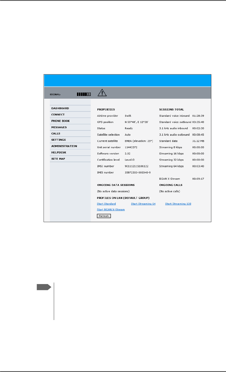
Use the Dashboard
6-22 Chapter 6: Configure the AVIATOR 700 system 98-124743-F
6.5 Use the Dashboard
6.5.1 Overview
The Dashboard is the first screen that is displayed when the user or administrator enters the
IP address of the web interface. The Dashboard is used for control and inspection of
ongoing communication and for viewing properties and status of the SBU and antenna.
Figure 6-18: Web interface: Dashboard
6.5.2 Properties
The PROPERTIES section of the DASHBOARD shows the following information:
•Airtime provider. The name of your Airtime Provider.
•GPS position. The GPS position of your AVIATOR 700 system.
•Status. The status of the SBU and antenna.
Examples of status information are: Scanning, Ready and Data active.
•Satellite selection. The satellite selected for logon.This is handled by the SDU.
Note
In some cases, the BGAN network does not allow the position to be displayed to
the user. If this is the case, the display may just show GPS acquired. This
means that the GPS position is received, but the user is not allowed to see it.
This also applies if the AVIATOR 700 is not yet registered on the BGAN network,
but the GPS position is received.

Use the Dashboard
98-124743-F Chapter 6: Configure the AVIATOR 700 system 6-23
•Current satellite. The currently used satellite and elevation angle.
•Unit serial number. The serial number of the SBU.
•Software version. The version of the software embedded in the SBU.
•Certification level. This field shows whether the system is Level-D or Level-E certified.
If Inconsistent is displayed, it means there is a mismatch with Level-D
and Level-E certified units or software. This is not allowed.
•IMSI number. The IMSI number (International Mobile Subscriber Identity) of the SBU.
This is a unique number that identifies the SIM card of your SBU.
•IMEI number. The IMEI number (International Mobile Equipment Identity) of the
SBU. This is a unique number that identifies your SBU.
6.5.3 View information on calls and data sessions
The following sections in the Dashboard show information on calls and data sessions.
•ONGOING DATA SESSIONS is a list of data profiles that are currently active, including
the external IP address that is assigned to each profile.
•ONGOING CALLS is a list of calls that are currently active. The list shows the call type
and the time connected for each call.
•SESSIONS TOTAL lists the totals for each session type. The list shows the session type
with accumulated time for voice and Streaming data, and MB transferred for Standard
data.
The counters show totals for sessions since the counters were last cleared. For information
on how to clear the counters, see Log handling on page 6-75.
Important
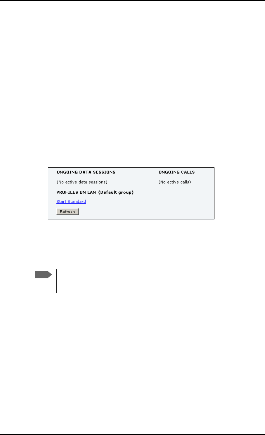
Use the Dashboard
6-24 Chapter 6: Configure the AVIATOR 700 system 98-124743-F
6.5.4 Profiles on the dashboard
There is also a section on the dashboard showing the network user group and the profile(s)
available for the current user. Here you can start the connections allowed for the current
network user group. For more information on network user groups and profiles see To
manage LAN/WLAN network users on page 6-54.
Start or stop a standard data connection
On the Dashboard you can see under PROFILES ON LAN whether a standard connection is
active or not.
To start or stop a Standard connection for your Network user group do as follows:
1. Open your Internet browser and enter the IP address of the AVIATOR 700 SBU (default:
http://192.168.0.1) to access the Dashboard of the web interface.
2. Locate PROFILES ON LAN at the bottom of the page.
3. Click Start <name of profile>, in this case: Start Standard, or Stop <name of
profile> to stop the connection.
Figure 6-19: Web interface: Start a data connection
4. Click Refresh to update the current state of the connection(s). Note that there might
be some latency when updating the connection status, you might have to wait and click
Refresh again to update the Dashboard to the current state.
Note
The PDP context for a data session is not activated before any unit in the LAN tries
to communicate, e.g. sends a DHCP request. You can also remotely start a data
connection, see Remote activation of a connection using SMS on page 6-87.
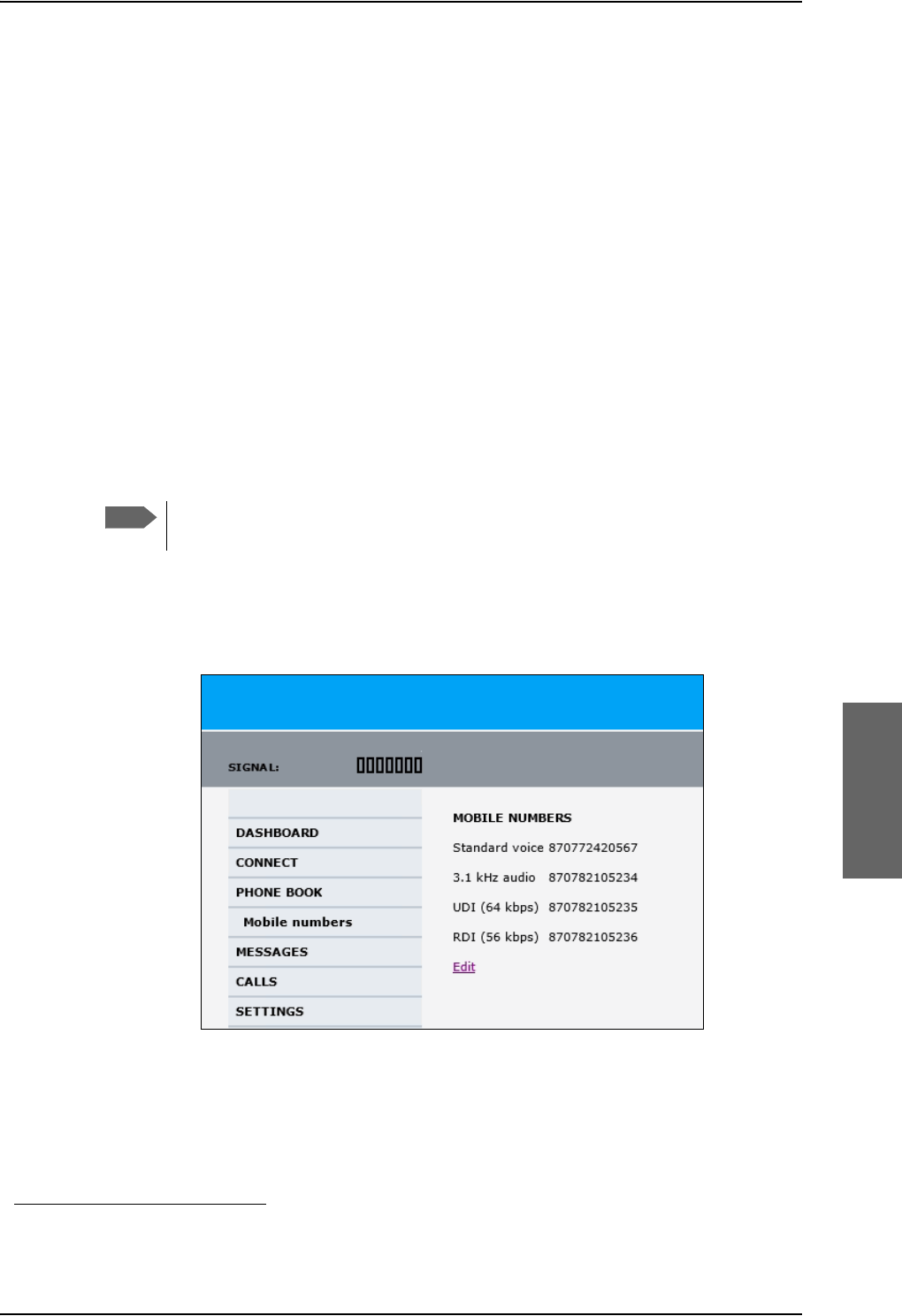
To use the phone book
98-124743-F Chapter 6: Configure the AVIATOR 700 system 6-25
6.6 To use the phone book
6.6.1 General usage
The phone book is stored in the Configuration module. In the phone book you can:
• Add new names and phone numbers.
• Modify or delete existing names and phone numbers.
•Look up phone numbers.
• Look up short-dial numbers for easy dialing from a handset.
For information how to access the phone book and how to add, edit and delete phone book
entries see the AVIATOR 700 User Manual.
6.6.2 View and edit the mobile and additional numbers1
The mobile numbers are the phone numbers to use when making a call to the terminal.
These numbers are not listed at delivery. Enter the numbers received from the
Service and Airtime Provider.
To view the mobile numbers
To view the mobile numbers of the SBU, select PHONE BOOK > Mobile numbers from
the left navigation pane.
Figure 6-20: Web interface: Phone book, mobile numbers (example, no Multi-voice)
1. Available for systems with Multi-voice and subscriptions with additional numbers.
Note
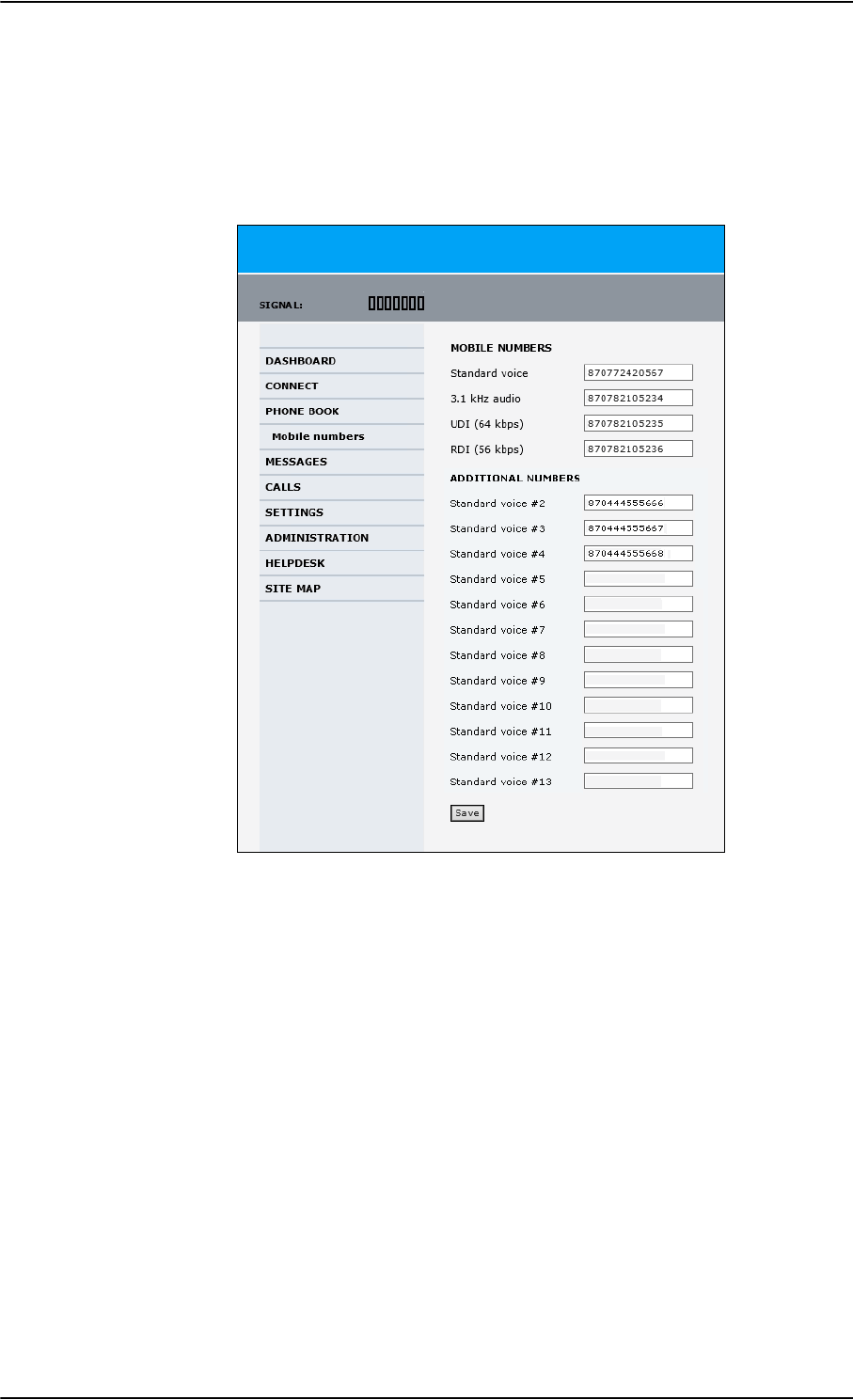
To use the phone book
6-26 Chapter 6: Configure the AVIATOR 700 system 98-124743-F
To enter or edit the mobile numbers
To enter or edit the mobile numbers, click Edit at the bottom of the page, type in the
numbers received from your Airtime Provider and click OK. If Multi-voice is part of your
system, the additional numbers from your airtime provider can be entered in the web
interface.
Figure 6-21: Web interface: Phone book, mobile numbers (example, with Multi-voice)

Set up the interfaces of the SBU
98-124743-F Chapter 6: Configure the AVIATOR 700 system 6-27
6.7 Set up the interfaces of the SBU
6.7.1 The SETTINGS page
From the SETTINGS page you have access to the submenus for system settings and
configuration:
•LAN to configure the settings of the local area network.
•WLAN to configure the wireless network adapter.
•Phone/Fax to configure the phone and fax interfaces.
•ISDN to configure the ISDN interface.
•Common to configure settings that are common for all interfaces.
•IP handsets to configure connected IP handsets.
•Discrete I/O to configure the discrete inputs/outputs of the installation.
•System type to select the AVIATOR 700 system
•RF settings to configure the cable losses between the satcom antenna and the SBU.
•External systems to configure the external navigational system.
•FLEX for system options.
•Tracking to send position information to a server
•Upload to upload new application software to the SBU.
A text message on the screen informs you if you need to reboot the system to activate a
new setting or configuration.
To access this page, select SETTINGS from the left navigation pane.
Select a submenu to continue the system configuration.
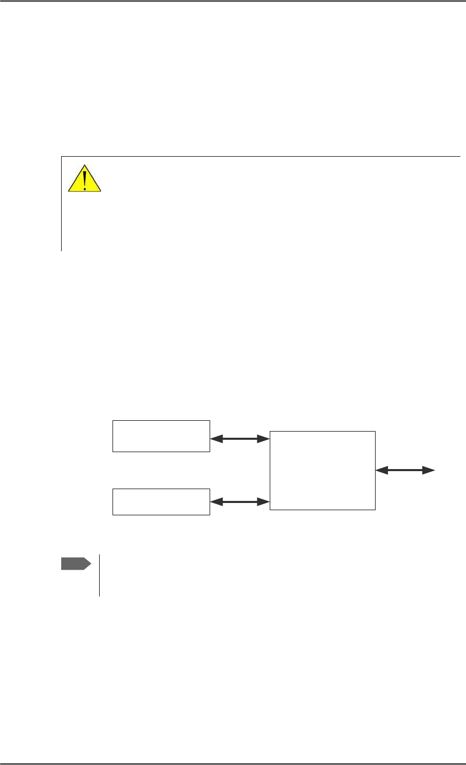
Set up the interfaces of the SBU
6-28 Chapter 6: Configure the AVIATOR 700 system 98-124743-F
6.7.2 Configure the LAN interface of the SBU
Overview
The SBU has 6 LAN connectors plus 1 LAN maintenance connector on the SBU front plate.
The major part of the LAN parameters are set up in the network management pages, which
require an administrator password. For information on these settings, refer to To manage
LAN/WLAN network users on page 6-54.
This page is by default not protected by an admin password. You can limit
access to this page for certain user groups, for further details see Set up user
permissions on page 6-84.
Set up the LAN IP addressing
In the web interface you can set up the IP addressing between the SBU and devices
connected to the SBU. The SBU has a built-in DHCP server which can be used to
dynamically assign IP addresses to devices connected to the SBU.
You can also set up the local IP address used by the connected devices to access the SBU.
The Local IP address is the IP address of the SBU. It is used for accessing the web interface.
The IP address towards the BGAN network is assigned by Inmarsat and visible on the
Dashboard when the connection is active.
Figure 6-22: SBU IP addresses: Local and global IP addresses, default
CAUTION! All connections to the LAN interface may be affected when
you change the settings below. This also includes your own current
connection.
Note
No router option: If the SBU does not have the router option and works in
single-user mode, only one device can be connected to it. This device cannot have
a static IP address, it must use the DHCP server of the SBU.
6%8
'HYLFH
'HYLFH
DVVLJQHGE\WKH
WHUPLQDO'+&3
DVVLJQHGE\WKH
WHUPLQDO'+&3
/RFDO,3
DGGUHVVRI
6%8
*OREDO,3
DGGUHVVRI
6%8
$VVLJQHG
E\%*$1
QHWZRUN
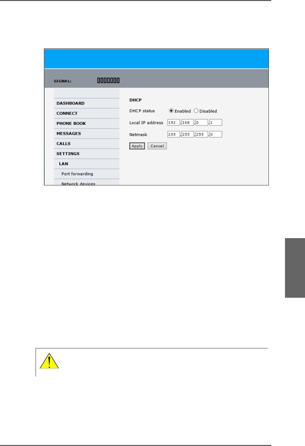
Set up the interfaces of the SBU
98-124743-F Chapter 6: Configure the AVIATOR 700 system 6-29
To change the local IP address of the SBU do as follows:
1. From the left navigation pane, select SETTINGS > LAN.
Figure 6-23: Web interface: Settings, LAN
2. At DHCP status, select Enabled (recommended), or Disabled.
•Enabled: The SBU assigns dynamic IP addresses to devices connected to the SBU.
•Disabled: You need to set up a static IP address in the connected device.
3. To change the Local IP address and the Netmask, type in the new address and
netmask. By default, the address is 192.168.0.1 and the netmask is 255.255.255.0.
4. Click Apply.
Port forwarding
Port forwarding enables you to set up a server connected to the SBU while the terminal is in
Router mode. Without port forwarding it would not be possible to contact the server from
the Internet. If you want to use port forwarding, the global IP address of the SBU should be
a static IP address. Check with your service provider for availability of a static global IP
address. Note that if not agreed otherwise, the global IP address of the SBU will be
dynamically assigned as the SBU signs on to the BGAN network.
For information on how to set the terminal in Router mode, see Set up the network user
groups on page 6-55.
The following example shows how to allow internet access to a mail server (smtp)
connected to the terminal.
CAUTION! This page is by default not protected by an admin password.
You can limit access to this page for certain user groups, for further details
see Set up user permissions on page 6-84.
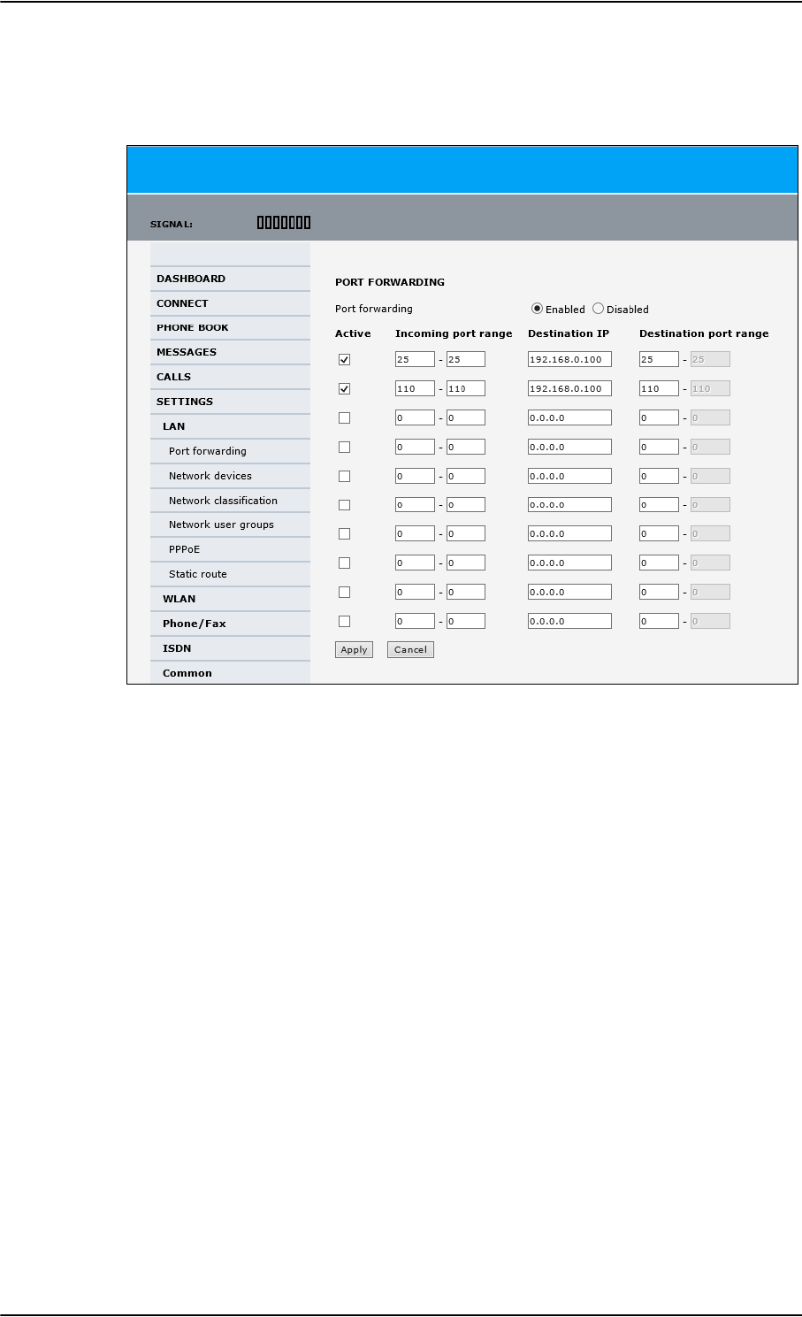
Set up the interfaces of the SBU
6-30 Chapter 6: Configure the AVIATOR 700 system 98-124743-F
The mail server in this example has the IP address 192.168.0.100.
1. Select SETTINGS > LAN > Port forwarding in the left navigation pane.
Figure 6-24: Web interface: Settings, LAN, Port forwarding
2. Select Enabled to generally enable port forwarding.
3. Type in the Incoming port range.
4. Type in the Destination IP address, which in this example is the IP address of the mail
server: 192.168.0.100.
5. Type in the Destination port range.
6. Repeat step 3 to step 5 to set up port forwarding to additional servers.
7. In the Active column, select which ports should have port forwarding activated.
8. Click Apply.
You can now access the mail server from the Internet, using the external IP address of the
SBU. For more information on setting an external IP address see step 6 in Edit a network
user group on page 6-56.

Set up the interfaces of the SBU
98-124743-F Chapter 6: Configure the AVIATOR 700 system 6-31
6.7.3 WLAN interface of the SBU (option)
Note that the settings from the LAN window, except Enabled/Disabled, also apply for the
WLAN interface. See Configure the LAN interface of the SBU on page 6-28.
Enable or disable the WLAN interface
To enable the WLAN interface, do as follows:
1. Make sure that the discrete input, i.e. TP5 WLAN Enable input, is wired correctly for
WLAN enable. Read more about this in Pins for non-configurable discrete inputs on the
SBU on page 5-68 and WLAN pins on page 5-43.
2. In the web interface on the page SETTINGS > WLAN select the status Enabled.
For systems without the built-in Wireless option (WLAN) the submenu will still be available
in the web interface and the screen will show that the WLAN option is not enabled. To
enable the WLAN option enter the FLEX key for this option in the submenu Settings >
FLEX.
The WLAN interface functions properly if both of the above conditions are fulfilled.
Set up the interfaces of the SBU
6-32 Chapter 6: Configure the AVIATOR 700 system 98-124743-F
Configure the WLAN interface
To configure the WLAN interface, do as follows:
1. Select SETTINGS > WLAN.
Figure 6-25: Web interface: Settings, WLAN
2. You can enable or disable the WLAN (default setting: Enabled).
3. For Broadcast SSID, select Enabled (default) or Disabled.
Enabled: your WLAN access point is shown to other users.
Disabled: your WLAN access point is hidden.
4. Type in the SSID of your choice or accept the default SSID, which is the name of the
installed system: AVIATOR 700.
The SSID (Service Set IDentifier) is the name of the wireless local area network. It is
text with maximum 32 characters.
All wireless devices on a WLAN must use the same wireless local area network in order
to communicate with each other.

Set up the interfaces of the SBU
98-124743-F Chapter 6: Configure the AVIATOR 700 system 6-33
5. Select the Country for your present location. The default setting is USA. For a list of
countries that can use WLAN with the setting USA see Countries where the “US”
country code applies on page E-2.
6. If you want to let the system automatically find a channel set Select channel
automatically to Enabled. Then the Channel list will be grayed out.
If you have set Select channel automatically to Disabled you can set the Channel
used for communication on the WLAN interface.
7. Select the Security standard. Select one of the following encryption standards:
• None (default)
•WEP-40/64, enter the encryption key in hexadecimal format.
• WEP-104/128, enter the encryption key in hexadecimal format.
• WPA-TKIP, enter the encryption key in text format.
• WPA2-AES, enter the encryption key in text format.
8. Type in the Encryption key for the selected Security standard. This is not applicable if
you have selected Security mode None.
9. In Antenna configuration you set whether you have two or one WLAN antennas,
and how a single WLAN antenna is connected to the SBU:
•Diversity: 2 WLAN antennas are connected
•Main: A single WLAN antenna is connected to SBU TP A4
•Aux: A single WLAN antenna is connected to SBU TP A2
10. TX output power level: You can control the maximum transmitted output power
from the SBU rear receptacle TP A2 or TP A4:
• 100% – 20 dBm, 100 mW
•50% – 17 dBm, 50 mW
• 25% – 14 dBm, 25 mW
11. Select Enabled or Disabled next to MAC address filters.
Enabled: You can set up a list of MAC addresses that are allowed access to your WLAN.
Any device whose MAC address is not on the list will be denied access.
Disabled: There will be no restrictions on MAC addresses.
12. If you have enabled MAC address filters, type in the Allowed MAC addresses.
The list may contain up to 16 MAC addresses.
13. Click Apply.
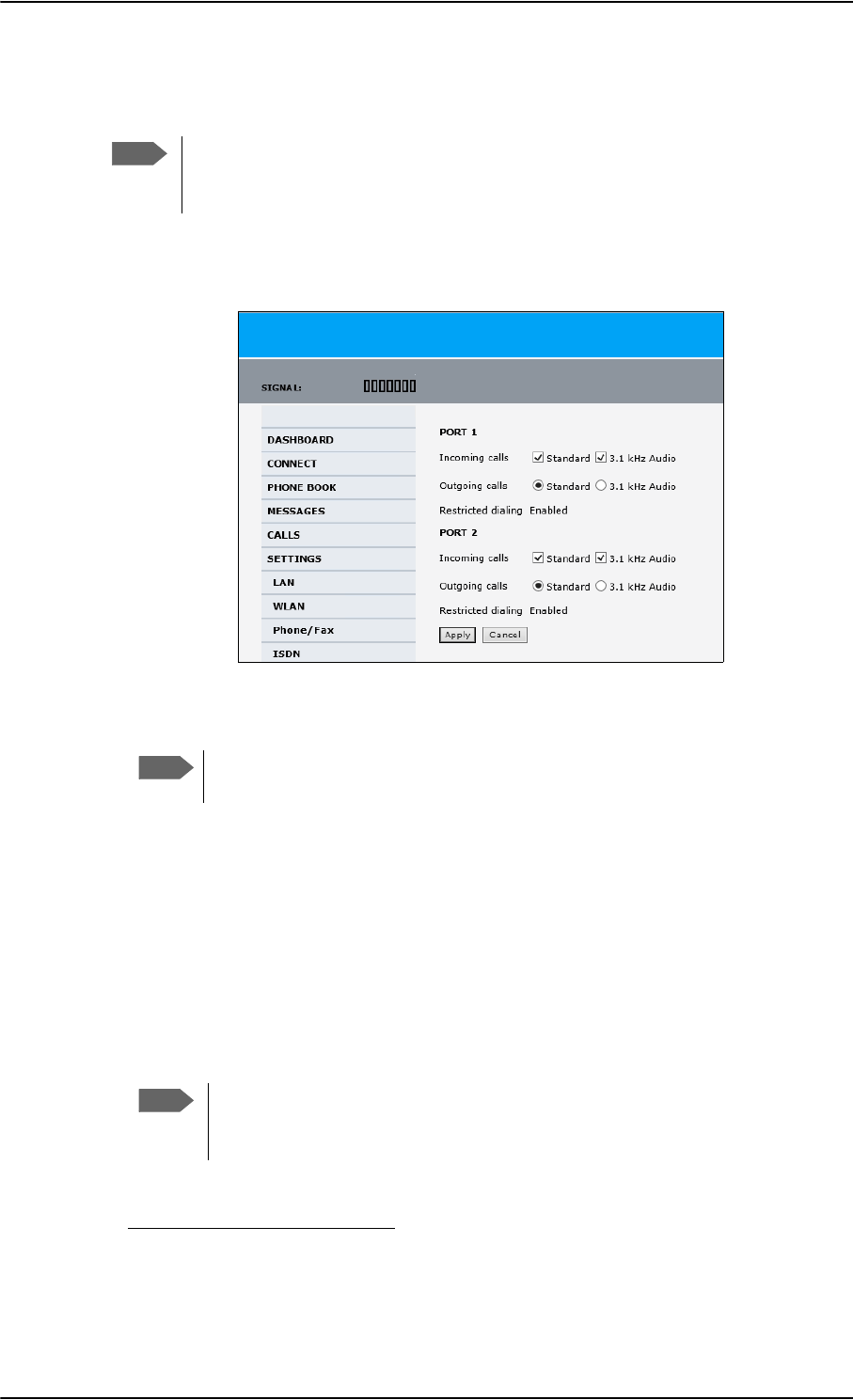
Set up the interfaces of the SBU
6-34 Chapter 6: Configure the AVIATOR 700 system 98-124743-F
6.7.4 Configure the Phone/Fax interface (2-Wire) of the SBU
To configure this interface do as follows:
1. Select SETTINGS > Phone/Fax from the left navigation pane.
Figure 6-26: Web interface: Settings, Phone/Fax
2. For each Phone/Fax port, set the call type for incoming and outgoing calls.
To identify Port 1 and Port 2 see the drawings of your specific installation.
Mark the connectors in the air cabin accordingly.
The call types are described in more detail in the AVIATOR 700 User Manual in the
chapter Using a phone of fax machine.
•For Incoming calls, you can check Standard or 3.1 kHz Audio or both.
If you check both, any device connected to the Phone/Fax interface will react (ring)
on incoming calls. 1
If you select only Standard, the Phone/Fax interface will only react on calls made to
the Standard phone number, and not on calls to the 3.1 kHz Audio number.
•For Outgoing calls, you can select either Standard or 3.1 kHz Audio. The selected
type will be used by default, if possible, for any outgoing call. Note, however, that fax
machines and modems must use 3.1 kHz Audio.
3. Click Apply.
Note
By default all handsets connected to the system will ring on incoming calls. If you
have connected a fax, set the incoming call type on that 2-wire interface to
3.1 kHz Audio to avoid that the fax rings and answers an incoming Standard call.
Note
1.If Multi-voice is enabled and you have entered additional numbers in the phone book,
you can assign an additional number to this interface. For more information see Multi-
voice (option) on page 6-88.
Note
You can override the default setting for outgoing calls by dialing 1* (force the
call to Standard) or 2* (force the call to 3.1 kHz Audio) before the number. For
further information, see the AVIATOR 700 User Manual.
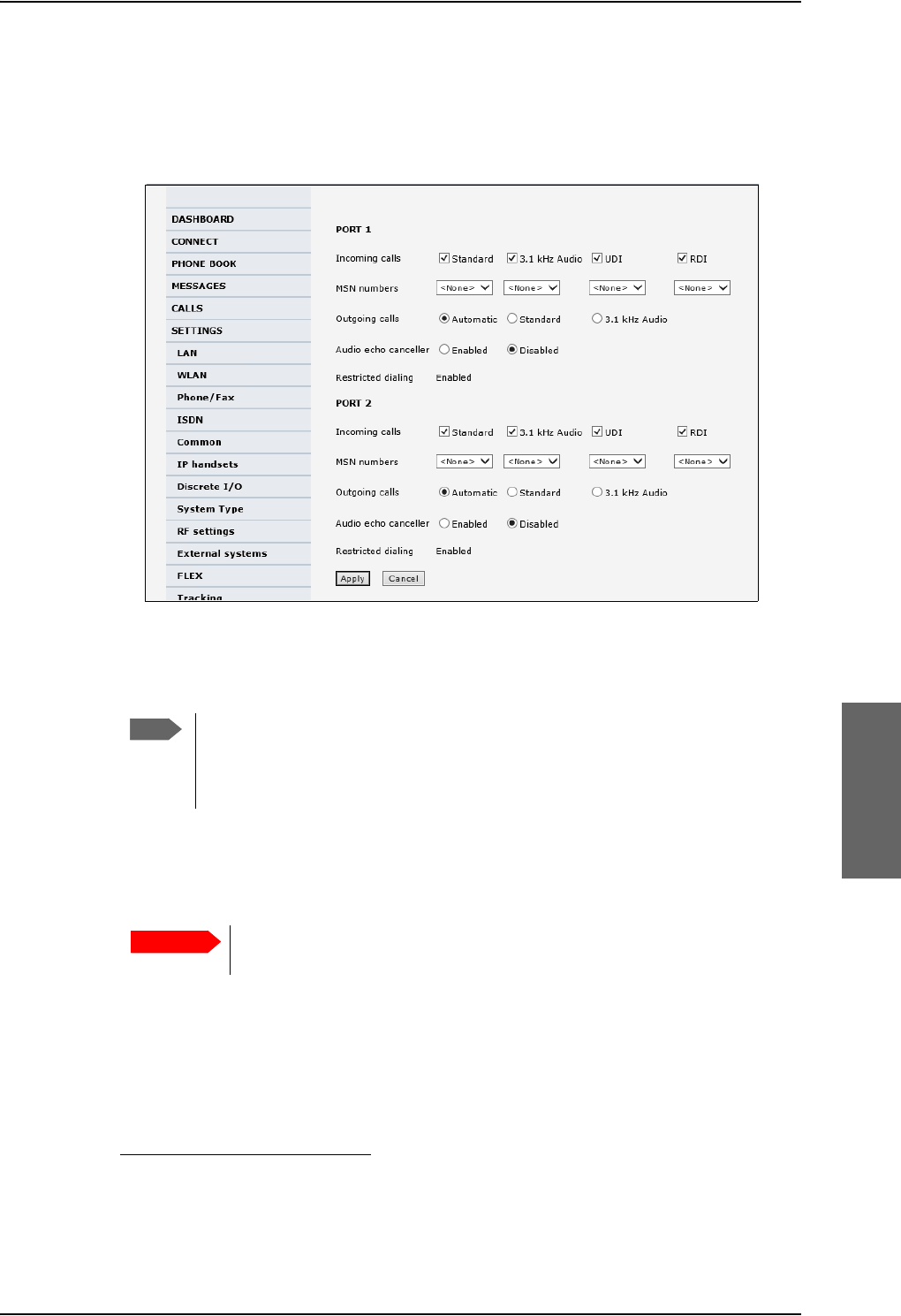
Set up the interfaces of the SBU
98-124743-F Chapter 6: Configure the AVIATOR 700 system 6-35
6.7.5 Configure the ISDN interface of the SBU
To configure the ISDN interface, do as follows:
1. Select SETTINGS > ISDN.
Figure 6-27: Web interface: Settings, ISDN
2. Set the call type(s) for incoming calls.
You can select Standard, 3.1 kHz Audio, UDI and/or RDI.1
3. Set the MSN (Multiple Subscriber Numbering) numbers that are to be assigned to each
call type. In most pieces of ISDN equipment you can program multiple subscriber
numbers. The number programmed into the equipment should be the dial-in number
that you wish that piece of equipment to answer.
If you set an MSN number to anything other than <None>, connected
devices must be programmed with these MSN numbers.
Note that this setting only applies to the call type selected above the MSN number, and
only if the connected device supports the call type used.
You have the following options with the MSN numbers:
•<None>. No MSN numbers are used. An incoming call is accepted in all devices
connected to this port.
1.If Multi-voice is enabled and you have entered additional numbers in the phone book,
you can assign an additional number to this interface. For more information see Multi-
voice (option) on page 6-88.
Note
Connected devices will only receive incoming calls with the call types that are
selected here. For example, if only Standard is selected, and a G4 fax call (using
call type UDI) arrives, a fax connected to the ISDN port will not receive the
incoming call.
Important

Set up the interfaces of the SBU
6-36 Chapter 6: Configure the AVIATOR 700 system 98-124743-F
•1*, 2*, 3* or 4*: If, for example, you select 1* at Standard call type, an incoming
Standard call is accepted by all devices that are programmed with the number 1* and
connected to the ISDN interface.
•0401, 0402: These are local numbers for separate devices connected to the ISDN
interface.
An incoming call is accepted by devices that are programmed with the selected
number and connected to the ISDN interface.
You can combine the MSN settings.
Example: You have two devices connected to the ISDN interface. One is
programmed with the numbers 1* and 0401, the other is programmed
with 1* and 0402.
In the web interface, you select the MSN number 1* under Standard.
If an incoming Standard call arrives, both devices will accept the call.
If you make a local call to one of the local numbers 0401 or 0402, only the
called device will accept the call.
4. Set the call type for outgoing calls.
•If you select Automatic, the call type will be determined by the calling device.
•If you select Standard, all outgoing calls, except UDI/RDI, will use the call type
Standard. If you make a 3.1 kHz Audio call it will be converted to a Standard call.
Outgoing UDI or RDI sessions will be not be influenced by this setting.
•If you select 3.1 kHz Audio, all outgoing calls, except UDI/RDI, will use the call type
3.1 kHz Audio. If you make a Standard call it will be converted to a 3.1 kHz Audio call.
Outgoing UDI or RDI sessions will be not be influenced by this setting.
5. If you hear an echo in your handset and the handset does not have its own echo
canceller, enable the Audio echo canceller.
6. Click Apply.
Note
You can override the call type setting for outgoing calls by dialing one of the
following prefixes before the number:
• 1* (force the call to Standard)
• 2* (force the call to 3.1 kHz Audio)
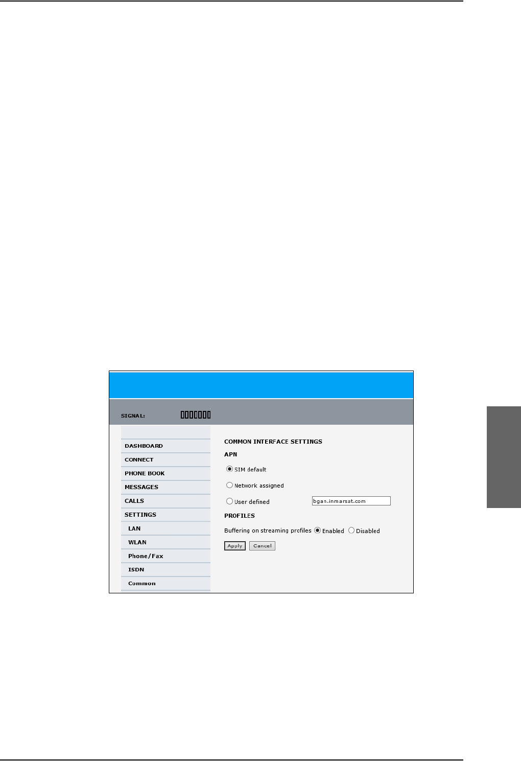
Set up the interfaces of the SBU
98-124743-F Chapter 6: Configure the AVIATOR 700 system 6-37
6.7.6 Set the common interface settings of the SBU
The settings under COMMON are common for all interfaces. Note, however, that in order to
use the common Access Point Name for an interface, you must select Common for the
APN setting when setting up the network user group.
Definition of Access Point Name (APN)
The APN is used by the network user to establish a connection to the required external
network. This means that the SBU must know the APN in order to be able to connect to the
external network. APNs are provided from the Airtime Provider. They may also be defined
on the SIM card.
The common APN
The common APN setting is defined here and can be selected for each network user group.
If you are using the same APN for many network user groups, it is easier to define it once,
and then simply select it for the relevant network user groups. Also, if you change the
common APN at a later stage, it is automatically updated for all network user groups where
the Common setting is selected.
To set up the common interface settings
To set up the Common interface settings do as follows:
1. Select SETTINGS > Common.
Figure 6-28: Web interface: Settings, Common
2. Select the APN. You have the following options:
•SIM default. The APN is taken from the SIM card. This is the recommended option,
unless you have special requirements, i.e. your service provider does not
automatically provision for PS services.
•Network assigned. The APN is assigned from the network.

Set up the interfaces of the SBU
6-38 Chapter 6: Configure the AVIATOR 700 system 98-124743-F
•User defined. Type in the APN. APNs are provided from the service provider.
3. At Buffering on Streaming profiles, select Enabled or Disabled.
•If you select Enabled, your Streaming connection will be buffered. This means that
the transmission is slightly delayed in order to ensure a precise and continuous data
stream.
•If you select Disabled, the Streaming connection will not be buffered. This means
the data is delivered immediately, but may vary slightly in transmission speed.
4. Click Apply.
How to use the common APN
When you configure the APN for your individual network user group, select Common to
use the setting from this page.
Where Common is selected in the individual network user groups, the setting will
automatically be updated when the Common APN is changed.
6.7.7 Set up call services
The setup of call services is also common for all interfaces.
The SBU must be registered on the BGAN network before
you can set up the call services in the web interface.
In the web interface you can set up the following supplementary services:
•Call forwarding
•Call barring
•Call waiting
•Line identification
•Closed user group
•Local exchange
Note that, depending on the network, some of these call service settings may prevent
others from being activated.
The settings apply for all connected devices using a circuit-switched service.
Note
Use User defined if your service provider does not automatically provision your
SIM card. Contact your service provider for an APN or check the
documentation received from the service provider for an APN.
Note
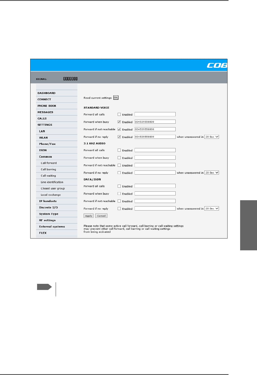
Set up the interfaces of the SBU
98-124743-F Chapter 6: Configure the AVIATOR 700 system 6-39
Call forwarding
You can set up the SBU to automatically forward incoming calls to another phone number.
To forward incoming calls do as follows:
1. Select SETTINGS > Common > Call forward from the left navigation pane.
Figure 6-29: Web interface: Settings, Common, Call forward
2. Click OK next to Read current settings to display the phone numbers for call
forwarding for the subscription. These numbers are operator controlled and come with
your airtime subscription (default). A message saying Operation in progress, please
wait. is displayed.
Allow sufficient time for the system to read the current settings over the
satellite connection.
3. For each call type, select Enabled next to the situation(s) in which you want to forward
incoming calls.
4. Next to the enabled items, you can type in a phone number to forward the call to.
5. If you have selected Forward if no reply, select from the drop-down list the period of
time the system should wait before forwarding the call.
6. Click Apply.
Note
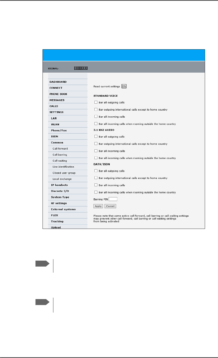
Set up the interfaces of the SBU
6-40 Chapter 6: Configure the AVIATOR 700 system 98-124743-F
Call barring
Do as follows to bar incoming and/or outgoing calls to and from the SBU:
1. Select SETTINGS > Common > Call barring from the left navigation pane.
Figure 6-30: Web interface: Settings, Common, Call barring
2. Click OK next to Read current settings. A message saying Operation in progress,
please wait. is displayed.
Allow sufficient time for the system to read the current settings over the
satellite connection.
3. For each call type, select which calls should be barred.
4. In the Barring PIN field, type in a PIN for your call barring setup.
5. Click Apply.
Note
Note
This is not the SIM PIN entered at startup, but a network PIN. Contact your
airtime provider for a Barring PIN.
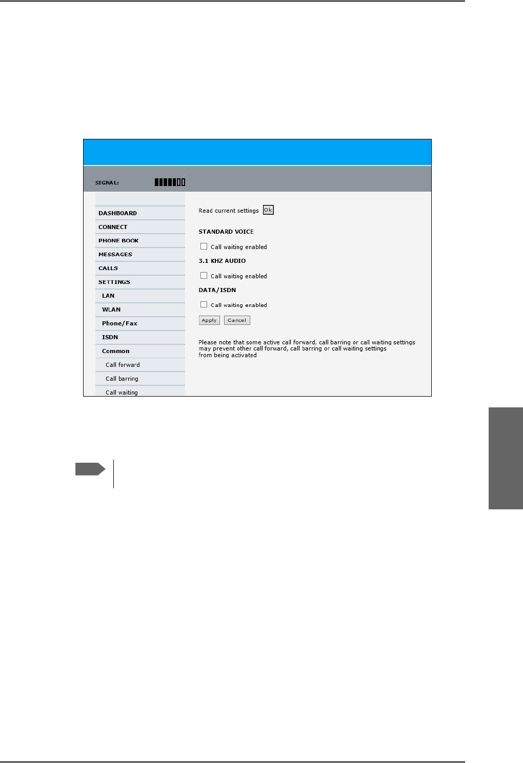
Set up the interfaces of the SBU
98-124743-F Chapter 6: Configure the AVIATOR 700 system 6-41
Call waiting
You can set up whether or not you want to receive notification of waiting calls while you
are making a call or transmitting data.
To receive a notification of waiting calls do as follows:
1. Select SETTINGS > Common > Call waiting from the left navigation pane.
Figure 6-31: Web interface: Settings, Common, Call waiting
2. Click OK next to Read current settings. A message saying Operation in progress,
please wait. is displayed.
Allow sufficient time for the system to read the current settings over the
satellite connection.
3. For each call type, select Call waiting enabled if you want to get notification of
waiting calls while you are making a call or transmitting data.
4. Click Apply.
Note
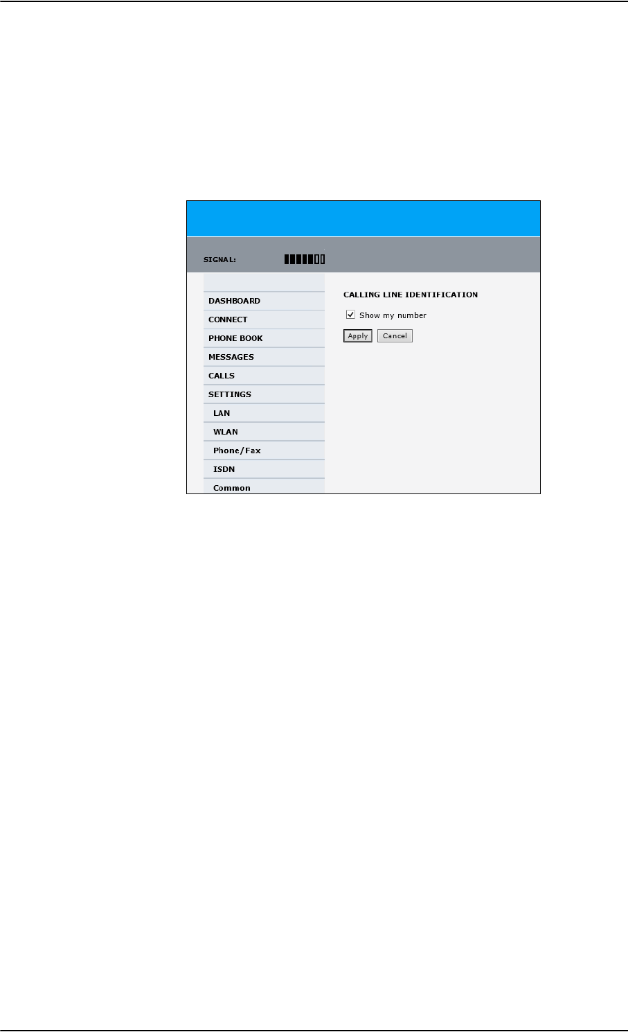
Set up the interfaces of the SBU
6-42 Chapter 6: Configure the AVIATOR 700 system 98-124743-F
Line identification
You can set up the terminal to show your number when you are making a call or
transmitting data. The number shown is the standard voice number of the airtime
subscription.
To show the number when making a call or transmitting data do as follows:
1. Select SETTINGS > Common > Line identification from the left navigation pane.
Figure 6-32: Web interface: Settings, Common, Line identification
2. Select Show my number and click Apply.
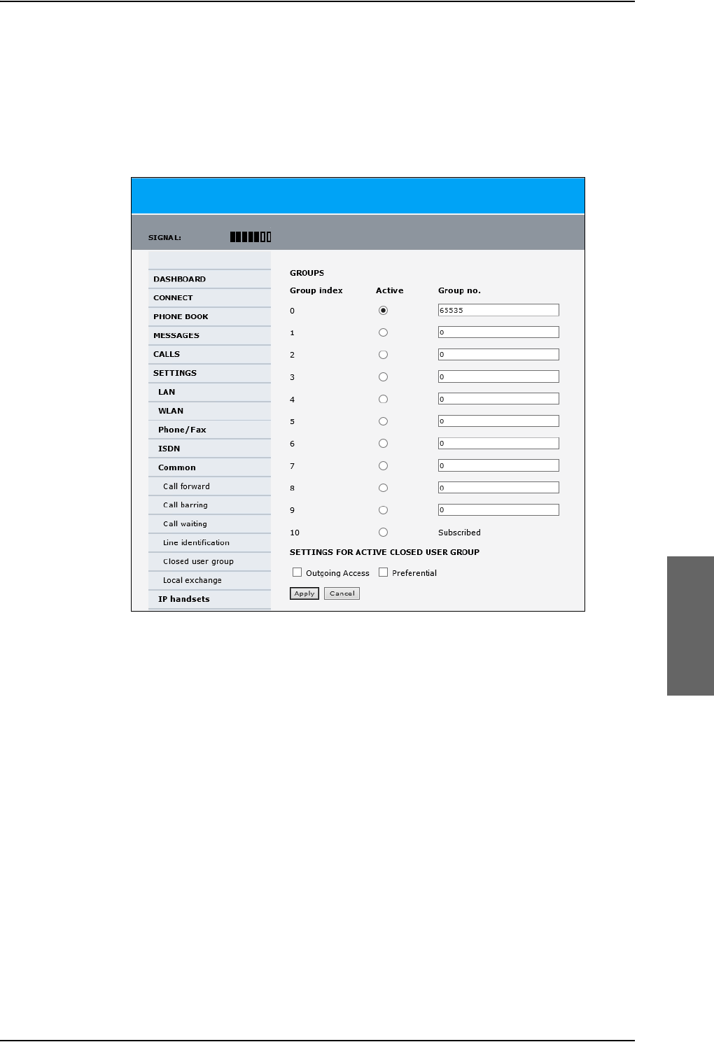
Set up the interfaces of the SBU
98-124743-F Chapter 6: Configure the AVIATOR 700 system 6-43
Closed user group
Your subscription may include one or more closed user groups. A closed user group is a
group of users permitted to make calls to each other but not to users outside the group. To
define the settings for these user groups, do as follows:
1. Select SETTINGS > Common > Closed user group from the left navigation pane.
Figure 6-33: Web interface: Settings, Common, Closed user group
2. Type in your user group number(s) under Group no.
Your airtime subscription lists your user group number(s).
3. Select which group(s) should be active.
If you select Active for Subscribed, the group(s) included in your subscription will be
active.
4. To allow outgoing access for the activated user group(s), select Outgoing Access
under SETTINGS FOR ACTIVE CLOSED USER GROUP. Note that if you selected
Subscribed above, this setting will not be used.
5. Select Preferential if you want the activated user group to be selected when a
member of a user group does not specify the group number during call set up. Note that
if you selected Subscribed above, this setting will not be used.
6. Click Apply.

Set up the interfaces of the SBU
6-44 Chapter 6: Configure the AVIATOR 700 system 98-124743-F
Local exchange
If you want to call a specific phone connected to the terminal, use the local exchange
function. With this function enabled, when you dial the mobile number of the terminal, a
recorded message instructs you to dial the number for the local phone you want to call.
Your call is then transferred to the requested phone and only the requested phone rings. If
the local exchange is not used, incoming calls will per default cause all connected phones to
ring.
The Local exchange function is not available if you have enabled the Multi-voice
option.
For a detailed description how to set up the local exchange function of the SBU from a
remote location see the AVIATOR 700 user manual.
6.7.8 Manage AVIATOR Wireless Handsets
Overview
The SBU uses WLAN to connect AVIATOR Wireless Handsets or other IP equipment. The
AVIATOR 700 supports connection of up to 16 AVIATOR Wireless Handsets.
Each handset must have a local number in the range 0501 to 0516 as well as a unique
password.
The handset with the local number 0501 is the master handset. This means you
can start/stop data sessions from the SBU with this handset, if the function is
allowed in the User permissions page. See Set up user permissions on page 6-84
for further information on user permissions.
Connect a new AVIATOR Wireless Handset
Do as follows:
1. Connect the handset to the WLAN interface of the SBU. For a step-by-step procedure
see the AVIATOR Wireless Handset and Cradle User Manual, section Connecting the
AVIATOR Wireless Handset to a wireless access point.
2. When the handset display shows in the upper right corner, the handset is ready
to make a call. If you want to configure the handset or change the password, see the
next section.
When the SBU and the AVIATOR Wireless Handset have recognized each other, a
Configure link appears next to the handset in the IP handsets page of the web interface.
This link provides direct access to the built-in web interface of the AVIATOR Wireless
Handset. For further information, refer to the AVIATOR Wireless Handset and Cradle User
Manual.
Note
Note
Note
By default, a handset connected to the LAN interface on the terminal is
automatically registered in the terminal and assigned the first available local
number.
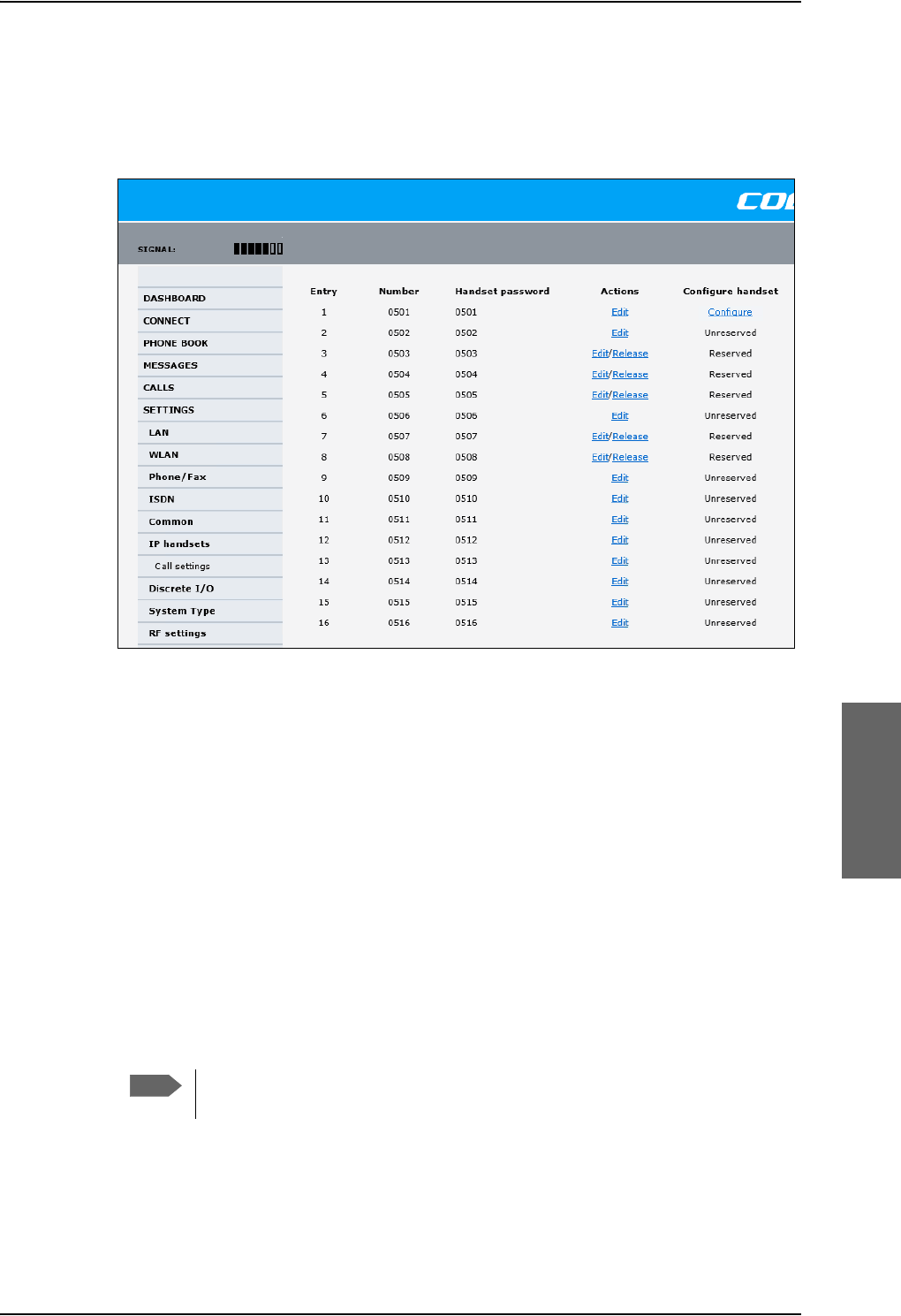
Set up the interfaces of the SBU
98-124743-F Chapter 6: Configure the AVIATOR 700 system 6-45
Set up the AVIATOR Wireless Handset
To set up an AVIATOR Wireless Handset, do as follows:
1. Select SETTINGS > IP handset.
Figure 6-34: Web interface: Settings, IP handsets
2. Select Edit next to a handset to change the password of the handset.
Remember that you must enter the same password and local number (user name) in the
handset. Use the display menu system to enter the local number and the password you
just entered in the web interface. Do as follows:
1. Enter the menu system and select SIP to get the list of profiles.
2. Select the BGAN profile and select Options.
3. Select Edit/View and change the user name and password.
Note that the user name is also the local number for the handset.
3. If you want to remove a handset from the list, click Release under Actions (the
Release link only appears when the handset is disconnected).
When a handset is removed from the list, you can no longer access the SBU with this
handset.
4. Select Configure next to a handset to access the built-in web interface of the
AVIATOR Wireless Handset.
The web interface of the handset opens. It is very similar to the web interface of the
SBU, but has a handset icon in the top left corner.
Note
You can only access the web interface of the handset if Web server is enabled
under Settings > Web server in the handset menu (default enabled).
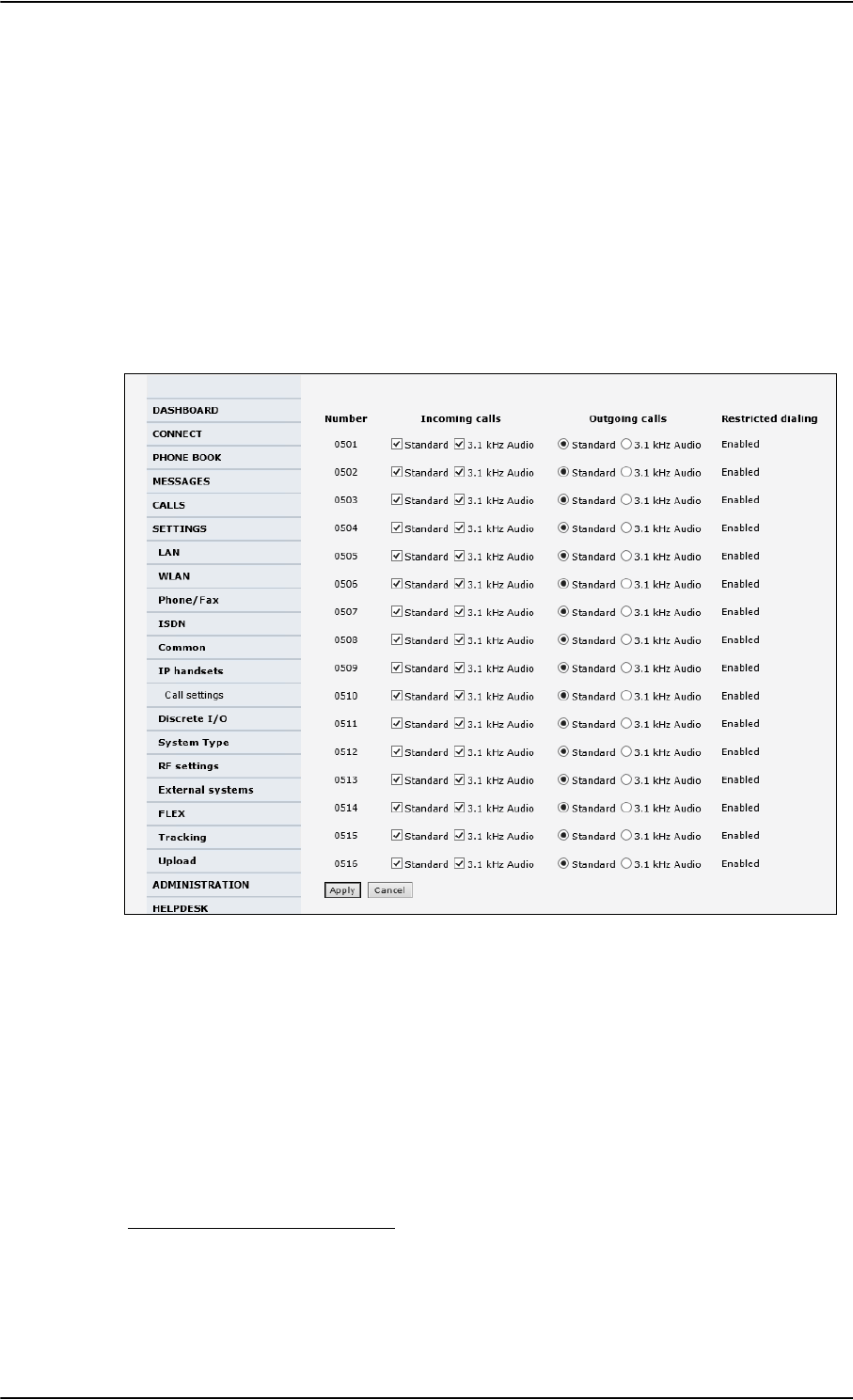
Set up the interfaces of the SBU
6-46 Chapter 6: Configure the AVIATOR 700 system 98-124743-F
With the web interface of the IP handset you can access the internal settings of the
handset. For further information, refer to the AVIATOR Wireless Handset and Cradle
User Manual.
Set the call types for AVIATOR Wireless Handsets
On this page you set the call type and you can see whether Restricted dialing is enabled
for each handset. For information how to set up restricted dialing see the AVIATOR 700
user manual.
To set the call types for AVIATOR Wireless Handsets, do as follows:
1. Select SETTINGS > IP handsets > Call settings.
Figure 6-35: Web interface: Settings, IP handsets, Call settings
2. For each handset, select the call types you want to enable for incoming and outgoing
calls.
The call types are described in more detail in the User Manual.
•Fo
r Incoming calls, you can check Standard or 3.1 kHz Audio or both. If you check
both, the handset will react (ring) on any incoming call. Example: If you select
Standard, the handset will only react on calls made to the Standard phone number.1
•For Outgoing calls, you can select either Standard or 3.1 kHz Audio. The selected
type will be used by default, if possible, for any outgoing call.
3. Click Apply.
1.If Multi-voice is enabled and you have entered additional numbers in the phone book,
you can assign an additional number to each IP handset. For more information see
Multi-voice (option) on page 6-88.

Set up the interfaces of the SBU
98-124743-F Chapter 6: Configure the AVIATOR 700 system 6-47
6.7.9 Configure the discrete I/O interfaces of the SBU
Overview
The SBU has 4 annunciators, 1 chime/lamp inhibit and 5 non-configurable discrete inputs.
The non-configurable discrete inputs are SBU nOn (remote on/off), SBU Enable, WLAN
Enable and two for Automatic Test Equipment (ATE). The ATE inputs are only for factory
use, do not connect them.
Each I/O pin that can be configured is displayed in the web interface. For more information
on the pins TP (Top Plug) and BP (Bottom Plug) see Pin-out for SBU rear receptacle (top
plug) on page 4-17 and Pin-out for SBU rear receptacle (bottom plug) on page 4-18.
The functions of the I/O pins are as follows:
•Pin TP13: Input. Chime/Lamps Inhibit Input.
This discrete input is used to inhibit Satcom activation of the chime and call lights
during take-off and landing.
•Pin TP27: Output. Annunciator #3 “Service Available”.
Default behavior: Active low when the SwiftBroadband Service is logged on
•Pin TP28: Output. Annunciator #1 “Incoming call”.
Default behavior: Active low when a handset is ringing.
•Pin TP29: Output. Annunciator #2 “SBU Failed”.
Default behavior: Active low whenever a BITE with severity essential or fatal is active on
the SBU.
•Pin BP1: Output. Annunciator #4 “Message received”
This discrete output can be used to indicate that there is an unread message in the SBU.
Default behavior: Active low.
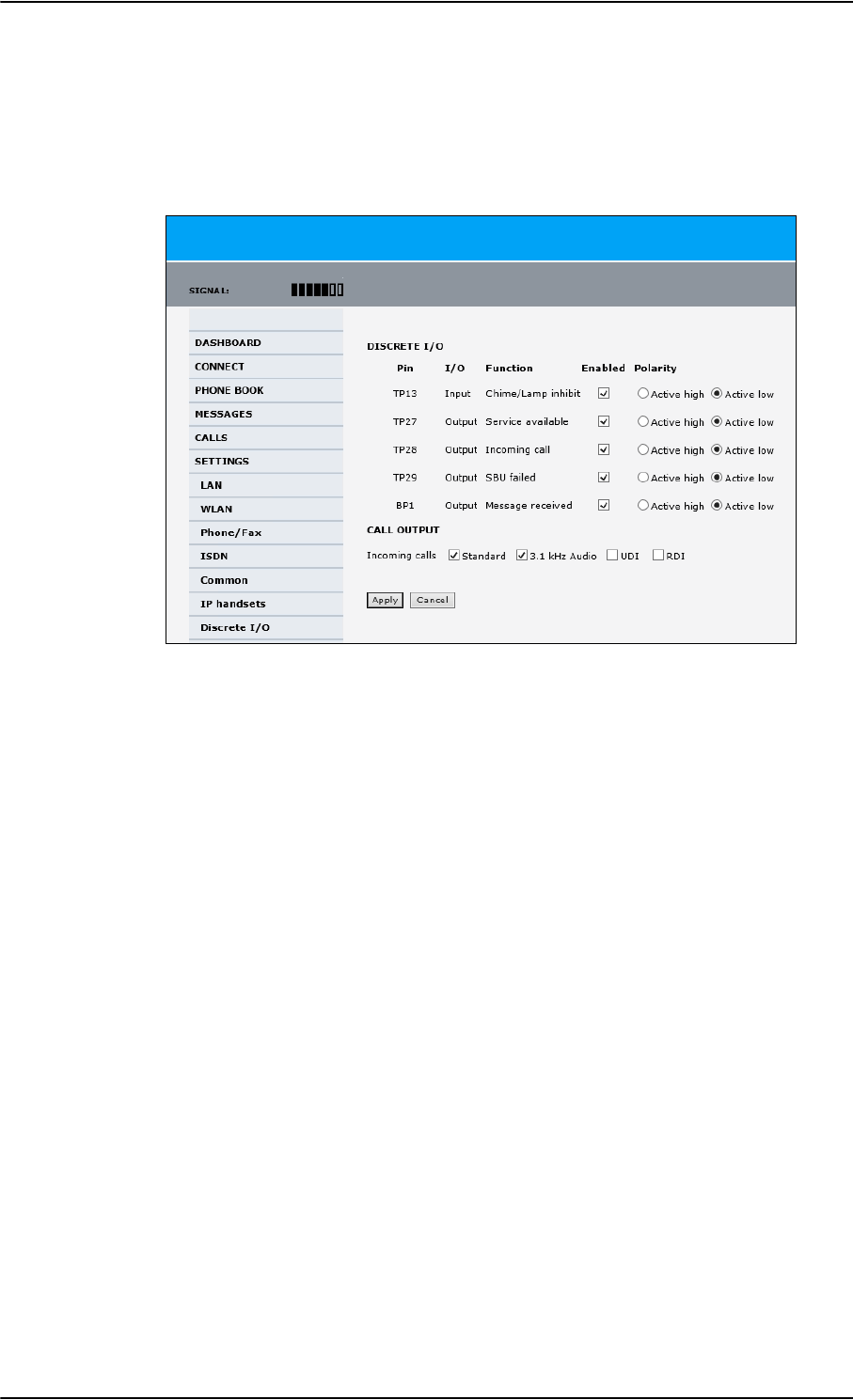
Set up the interfaces of the SBU
6-48 Chapter 6: Configure the AVIATOR 700 system 98-124743-F
Set the discrete I/O interfaces
You can enable and set some of the discrete I/Os in the web interface. To set these, do as
follows:
1. Select SETTINGS > Discrete I/O.
Figure 6-36: Web interface: Settings, Discrete I/O
2. For each pin you want to use, select Enabled.
3. For each pin, select if the pin should be Active high or Active low.
4. For Call output you can select which incoming calls will activate the external ringer
(Discrete I/O TP28: Incoming call).
5. Click Apply to save the new settings.
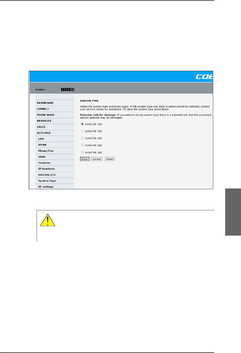
Set up the interfaces of the SBU
98-124743-F Chapter 6: Configure the AVIATOR 700 system 6-49
6.7.10 Set the System type
During the initial configuration of the system you must assign the system type, that is the
AVIATOR 700 system that you have bought. You can typically only select the system type
purchased.
To select the system type, do as follows:
1. Select SETTINGS > System Type.
Figure 6-37: Web interface: Settings, System Type
2. Select the system type for the installation.
Do not try to use a different system type!
3. Click Apply to save the new setting.
The Reset functionality is mainly used for support purposes.
CAUTION! Selecting a wrong system type may cause damage to the
satcom antenna or GPS antenna. If the system type purchased can not be
selected, please contact the supplier of your AVIATOR 700 system.
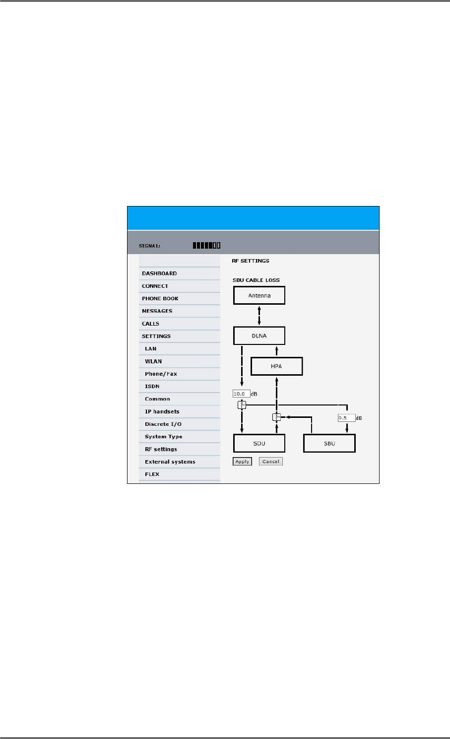
Set up the interfaces of the SBU
6-50 Chapter 6: Configure the AVIATOR 700 system 98-124743-F
6.7.11 Configure RF settings of the SBU
Before you can configure the RF settings you must select the system type.
You must configure the AVIATOR 700 installation with the specific cable losses of the
installation.
To configure the RF settings, do as follows:
1. Connect to the Maintenance connector on the front panel of the SBU and enter the
web interface (default: http://192.168.0.1)
2. If prompted, confirm that the system is an AVIATOR 700 system.
3. From the left navigation pane select SETTINGS > RF settings.
Figure 6-38: Web interface: RF settings
4. Below CABLE LOSS enter the cable loss for the cables between the
• DLNA and the RX Power Splitter
• RX Power Splitter and the SBU
The sum of the two cable losses must be equal or less than 21.5 dB. These cable loss
values are without losses from the RX splitter and TX combiner.
5. Click Apply to save the new settings.
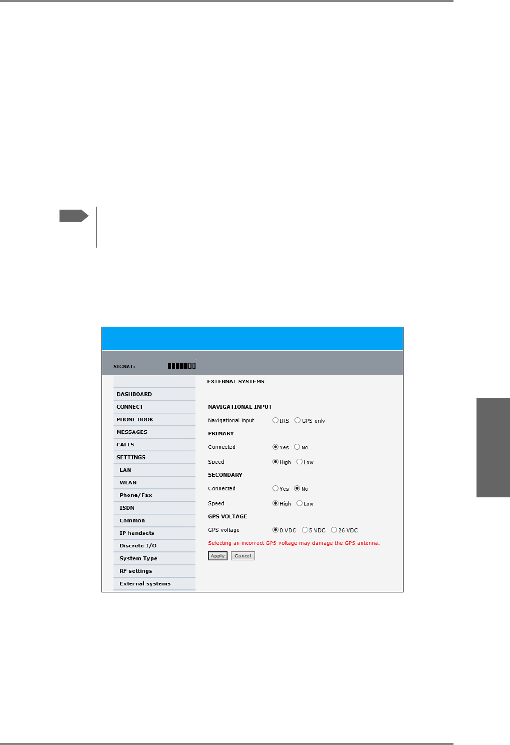
Set up the interfaces of the SBU
98-124743-F Chapter 6: Configure the AVIATOR 700 system 6-51
6.7.12 Set up the navigational input of the SBU
Before you can configure the navigational input you must select the system type.
The AVIATOR 700 supports IRS or GPS only.
For further information on supported navigational systems see About satcom antenna
steering on page 5-6.
ARINC 429 Speed can individually be set to high or low speed on the primary and
secondary input, depending on your configuration. For redundancy reasons the system
supports a secondary source, in case the primary source fails.
To set up the navigational input, do as follows:
1. Connect to the Maintenance connector on the front panel of the SBU and enter the
web interface (default address: http://192.168.0.1)
2. If prompted, confirm that the system is an AVIATOR 700 system.
3. From the left navigation pane select SETTINGS > External systems.
Figure 6-39: Web interface: Settings, External systems
4. For NAVIGATIONAL INPUT select one option.
5. Only for IRS: For Primary and Secondary select Connected and Speed.
6. Only for IRS: If you do not have second navigational input source available you must set
Connected of SECONDARY input to No.
Note
Make sure that you configure the primary and secondary IRS to the correct speed
in your configuration. This is essential to provide the necessary navigation data
needed.
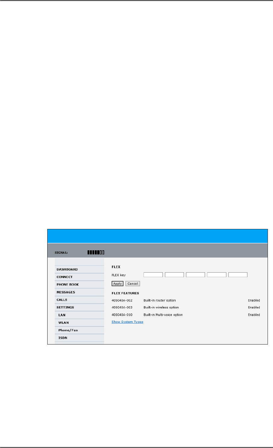
Set up the interfaces of the SBU
6-52 Chapter 6: Configure the AVIATOR 700 system 98-124743-F
7. GPS Voltage: If GPS only is selected and power to the GPS antenna is provided by the
SBU - apply the correct GPS voltage.
8. Click Apply to apply the new settings.
6.7.13 Enable system options with FLEX keys
On the FLEX page you can view the options for your system that are currently enabled or
disabled. Enabling the purchased options is typically done at the factory. The following
options are currently available:
•405040A-002 Built-in router option
•405040A-003 Built-in wireless option (WLAN)
•405040A-010 Built-in Multi-voice option
•405040A-005 SDU to SBU Software Interface
You can also buy the options at a later stage and open up for them by entering a FLEX key
sequence for the specific built-in option.
To enable a system option
To enable a built-in option, do as follows:
1. Connect to the Maintenance connector on the front panel of the SBU and enter the
web interface (default: http://192.168.0.1).
2. From the left navigation pane select SETTINGS > FLEX.
Figure 6-40: Web interface: Settings, FLEX (example)
3. Have the FLEX key ready and enter it into the insert fields.
4. Click Apply to enable the new option.
Click Show System Types to display the system types and their status (enabled or
disabled).
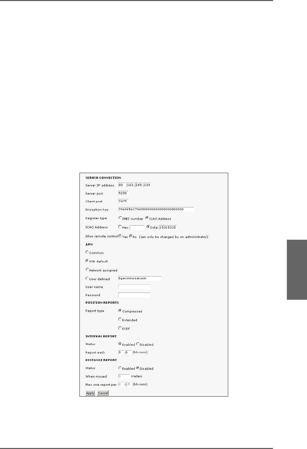
Set up the interfaces of the SBU
98-124743-F Chapter 6: Configure the AVIATOR 700 system 6-53
To disable the WLAN interface
To disable the built-in WLAN interface, do as follows:
• Disable the WLAN interface using the TP5 WLAN Enable discrete input. Read more
about this in Pins for non-configurable discrete inputs on the SBU on page 5-68 and
WLAN pins on page 5-43.
or
• In the web interface go to Settings > WLAN and select Disable.
If the WLAN option is not enabled the page Settings > WLAN will still be available and the
screen will show information that the WLAN option is not enabled.
6.7.14 Tracking
With tracking you can set the SBU to send reports with current position information at
specified time intervals or distances to a server address. To set up tracking, do as follows:
1. Select SETTINGS, Tracking.
Figure 6-41: Web interface, Settings, Tracking
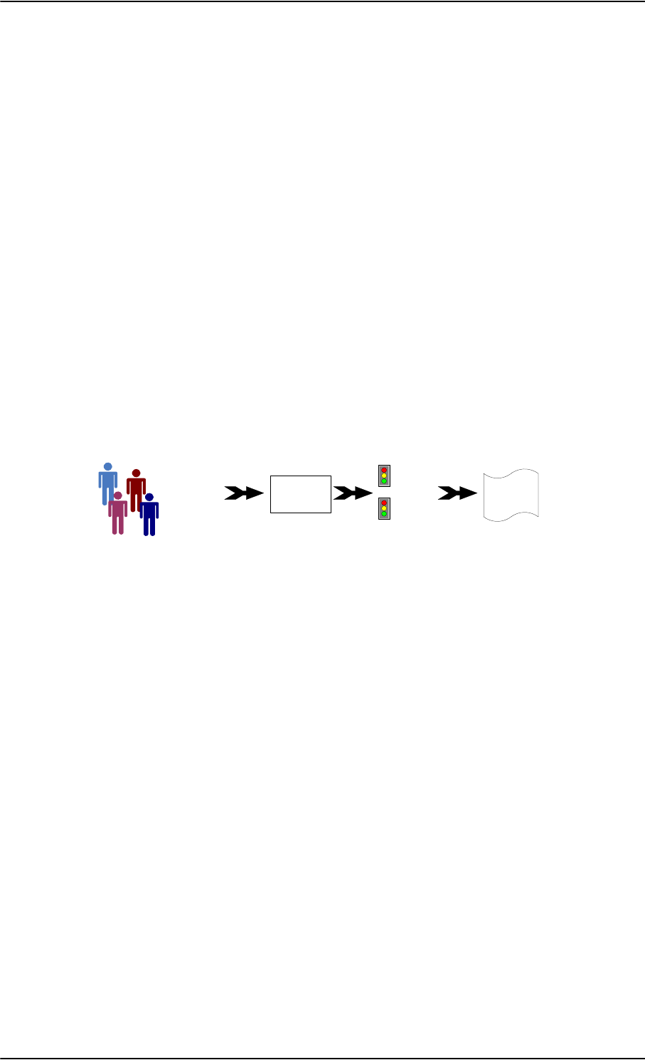
To manage LAN/WLAN network users
6-54 Chapter 6: Configure the AVIATOR 700 system 98-124743-F
2. The information in the sections SERVER CONNECTION and APN must be provided
by your airtime provider.
3. In POSITION REPORTS you can select among the following:
•Compressed: Aircraft’s position with latitude and longitude.
•Extended: Aircraft’s position latitude, longitude, heading, speed and UTC time.
•ECEF: Aircraft’s position in x,y,z coordinates and a velocity vector.
4. In INTERVAL REPORT and DISTANCE REPORT you can enable the respective
report and set a report interval or distance.
5. Click Apply to save the settings.
6.8 To manage LAN/WLAN network users
6.8.1 Introduction
With the built-in router functionality the system offers a flexible use of the data channel of
the BGAN service. You can configure the use of the data channel by defining network user
groups and profiles. The following picture gives an overview of the parameters involved.
Figure 6-42: Overview over network user groups and traffic flow filters
The network user group you belong to is determined by one or more of the following:
• the IP address of the device you are using
• the MAC address of the device you are using
• the LAN port you connect to
A connected IP device will automatically be assigned to the default network user group, if it
is not specified otherwise.
For specific purposes like video streaming, a server on the network, a fixed IP address on the
connected device or changing the startup mode of a connection, you must set up network
groups with specific primary and/or secondary profiles. How to do this is described in the
following sections.
Network user groups
The network management system divides the users of the SBU into network user groups.
Each network user group has a profile which determines how the users connect to the
Inmarsat BGAN network. The network user groups can allow or restrict certain services for
different users.
For example, you may want to define:
• one network user group allowing both Standard and Streaming connections,
MAC address
IP address
LAN port
Network
user
group
Primary
profile
Secondary
profile
Traffic flow
filters
Desired IP
connection

To manage LAN/WLAN network users
98-124743-F Chapter 6: Configure the AVIATOR 700 system 6-55
• one network user group for Internet, e-mail and VPN, allowing Standard connections,
• one network user group for Remote management of systems. This would be a direct
Standard connection (Bridge mode).
You can have up to 11 network user groups and global IP addresses.
Necessary steps when managing network users
The steps necessary for managing network users include:
1. Defining a network user group. See Set up the network user groups on page 6-55.
The network user groups determine settings such as:
•QoS (Standard/Streaming),
• IP addressing (Static or Dynamic, this is decided by the SIM card setup and the
service provider)
• Internet access mode (Router Mode, Bridge Mode or No Internet Access)
2. Identifying a network device. See Manage network devices on page 6-59. The
network devices are identified by their IP address, MAC address and (optionally) device
name.
3. Associating the network user group and the network device. See The network
classification table on page 6-60. The network classification table determines which
devices should belong to which network user group. When a network device is
connected, the SBU runs through the network classification table to check if the new
connection matches any of the entries in the table. When a match is found, the SBU
establishes a packet data connection (PDP context) with the settings determined for
the belonging network user group, and the device is ready for use with the SBU.
Access to the network management settings
Access to the network management settings requires an administrator password. The
default user name is admin and the default password is 1234.
The administrator can create and manage network user groups and set up a network
classification table defining priorities for devices, network user groups and LAN ports.
6.8.2 Set up the network user groups
Overview
A network user group, in this context, is a group of network users sharing the same Quality
of Service profile and network parameters.
There are 11 configurable network user groups. For the Default network user group, certain
settings are locked, to make sure there is always one functional network user group
Important
All user connections to the LAN interface may be
affected when you change the settings below,
including your own current connection.
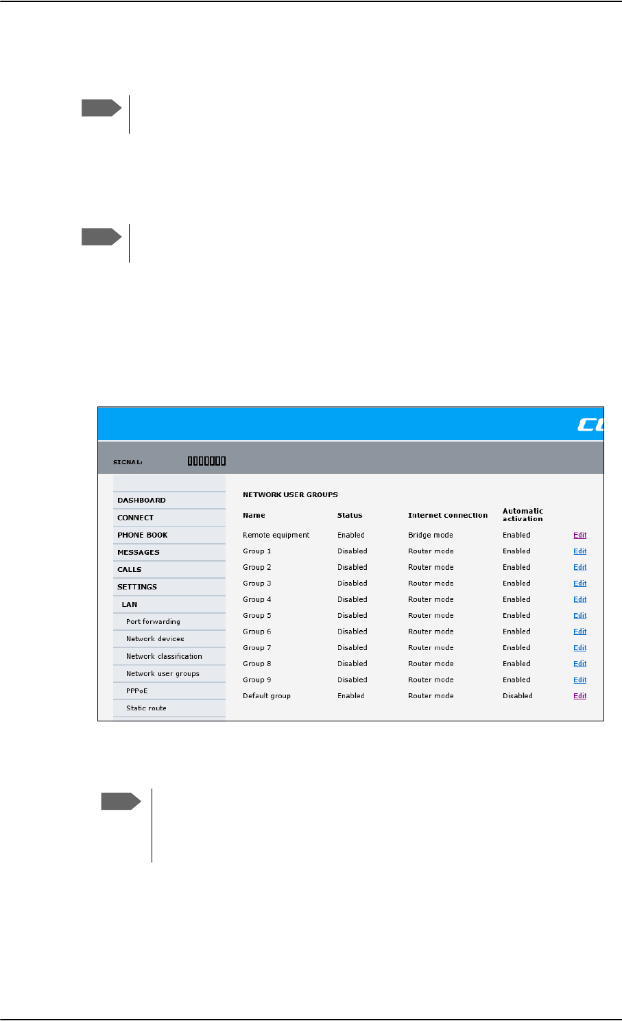
To manage LAN/WLAN network users
6-56 Chapter 6: Configure the AVIATOR 700 system 98-124743-F
available. For example, the Default network user group does not allow you to select a Bridge
mode connection.
You cannot delete network user groups. If you do not want to use them, click Edit
and select Disabled at Status in the NETWORK USER GROUP field.
Edit a network user group
The default setting of this network user group is a standard IP data connection with
automatic IP address allocation and automatic activation of the connection.
For further explanation of the terms used below, see Definitions for network
terms on page 6-62.
To edit a network user group, do as follows:
1. Select SETTINGS > LAN > Network user groups.
If prompted, enter the administrator user name and password. The default user name is
admin and the default password is 1234.
The following screen shows the 11 user groups available and their current status,
Internet connection type, and whether automatic activation is enabled or disabled.
2. Click Edit next to the network user group you want to set up.
Note
Note
Figure 6-43: Web interface: Settings, LAN, Network user groups
Note
Changes to the status and internet connection only take effect after reboot of
the SBU. This is also valid if a user wants to change the network user group,
then the SBU must be restarted before the user has access to the new network
user group.
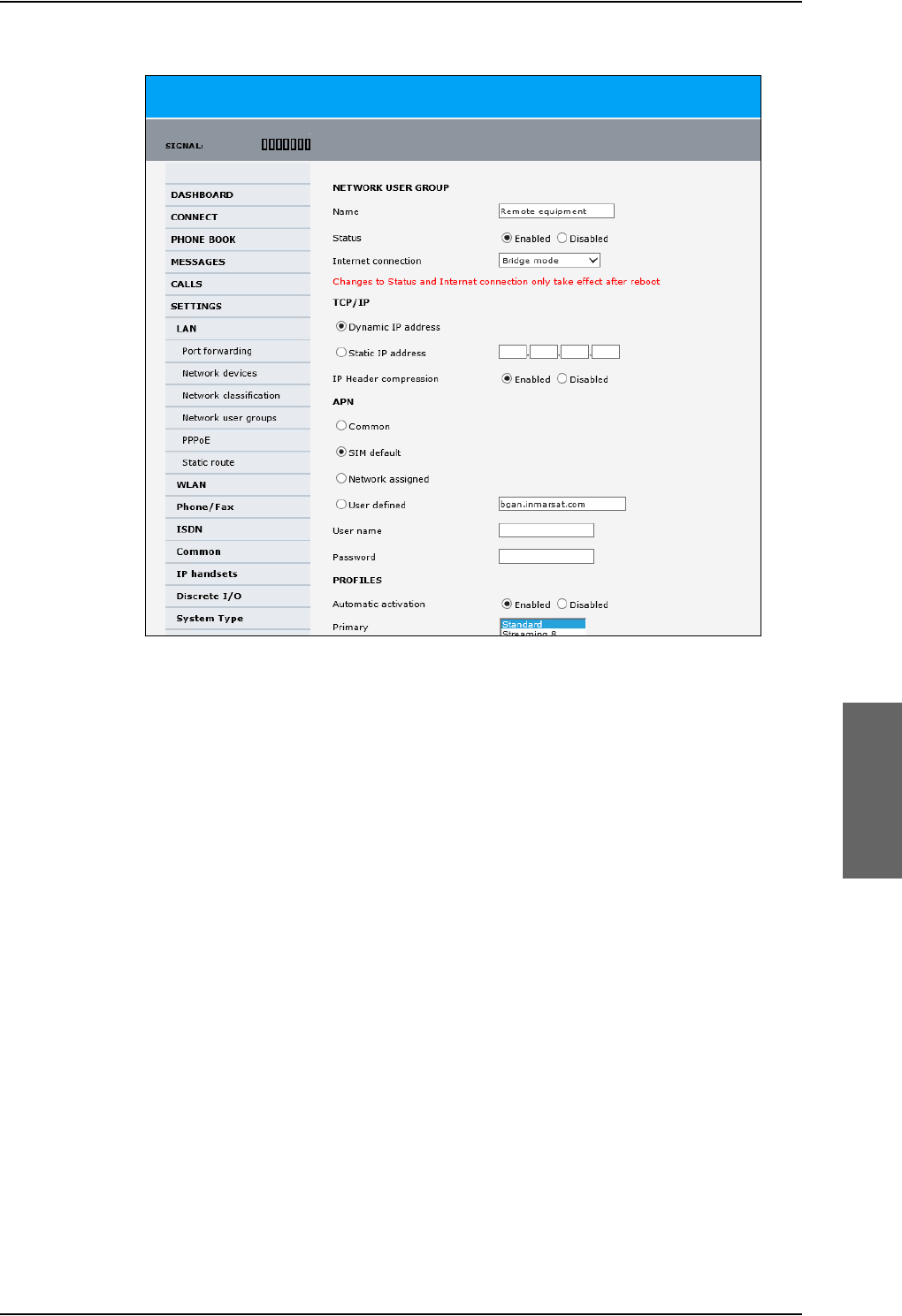
To manage LAN/WLAN network users
98-124743-F Chapter 6: Configure the AVIATOR 700 system 6-57
3. Type in a name for the group.
4. Select Enabled or Disabled.
5. Select the type of Internet connection.
•Router mode means the connection will be shared with other users, and the NAT
module of the SBU will make the necessary address translations. Read more about
NAT in NAT (Network Address Translation) on page 6-63. Use this mode if one or
more computers are connected using the LAN interface, and the SBU should acts a
router.
•Bridge mode is an exclusive connection, it is not shared with other users and NAT is
disabled. Use the Bridge mode together with a network classification entry that
selects a single computer (see The network classification table on page 6-60). The
SBU acts a a bridge for this network user group.
This mode is not available in the Default network user group.
•No internet access means no connection to the Internet is allowed. Use this
setting e.g. for IP handsets, where an Internet connection is not required. The
external voice connection is still available; this setting only affects communication
over the Internet.
6. Select Dynamic IP address.
This is the IP address used externally on the satellite network.
If you want to use a static IP address, and your subscription allows it, you must still
leave this setting at Dynamic. Then select SIM default in step 8 and type in the APN
user name and password from your provider in step 9.
Figure 6-44: Web interface: Settings, LAN, Network user groups, Edit

To manage LAN/WLAN network users
6-58 Chapter 6: Configure the AVIATOR 700 system 98-124743-F
Your SBU will then use the static IP address set up for your SIM card.
7. Set IP Header compression to Enabled or Disabled.
For information on IP Header compression, see Header compression on page 6-62.
8. Select the source of the APN (Access Point Name).
You have the following options:
•Common. The APN is taken from the Common APN defined under SETTINGS >
Common. Refer to Set the common interface settings of the SBU on page 6-37.
•SIM default. The APN is taken from the SIM card. If you want to use a static IP
address on the external network, select this option either here or in the Common
setting.
•Network assigned. The APN is assigned from the network.
•User defined. This is the preferred option. Type in the APN. APNs are provided
from the Airtime Provider. Use this option if there is no automatic provisioning for a
static IP address from the service provider.
9. If your APN uses a password, type in the user name and password provided from the
Airtime Provider.
10. At Automatic activation select whether the profile selected in the next step should
be activated automatically or manually.
•Disabled means you can activate/deactivate the profile from the Dashboard.
•Enabled means the profile is activated automatically.
11. Select the Primary profile.
Select a profile from the Primary scroll list. This profile is used by this network user
group as a first choice, when possible.
There are several predefined profiles: Standard, Streaming 8, Streaming 16, Streaming
32, Streaming 64 and Streaming 128. Additionally, you can define your own custom
profiles or any newer ones, Inmarsat defines.
For further information on profiles and traffic flow filters, see To use profiles on
page 6-75 and To use traffic flow filters on page 6-79.
12. Select the Secondary profile.
Note
Typing in a static IP address is currently not supported by the SwiftBroadband
network.
Note
If you are going to use the static IP address from your SIM card, the user name
and password are mandatory! See the documentation for the airtime
subscription from the service provider. See step 6 above.
Note
If the selected primary profile is a Streaming profile, this setting has no effect.
Streaming profiles must always be activated manually from the Dashboard.
Important
If you have selected and started a Streaming connection as your primary
profile, the LAN interface will be running a Streaming connection until you
stop it or disconnect the interface.
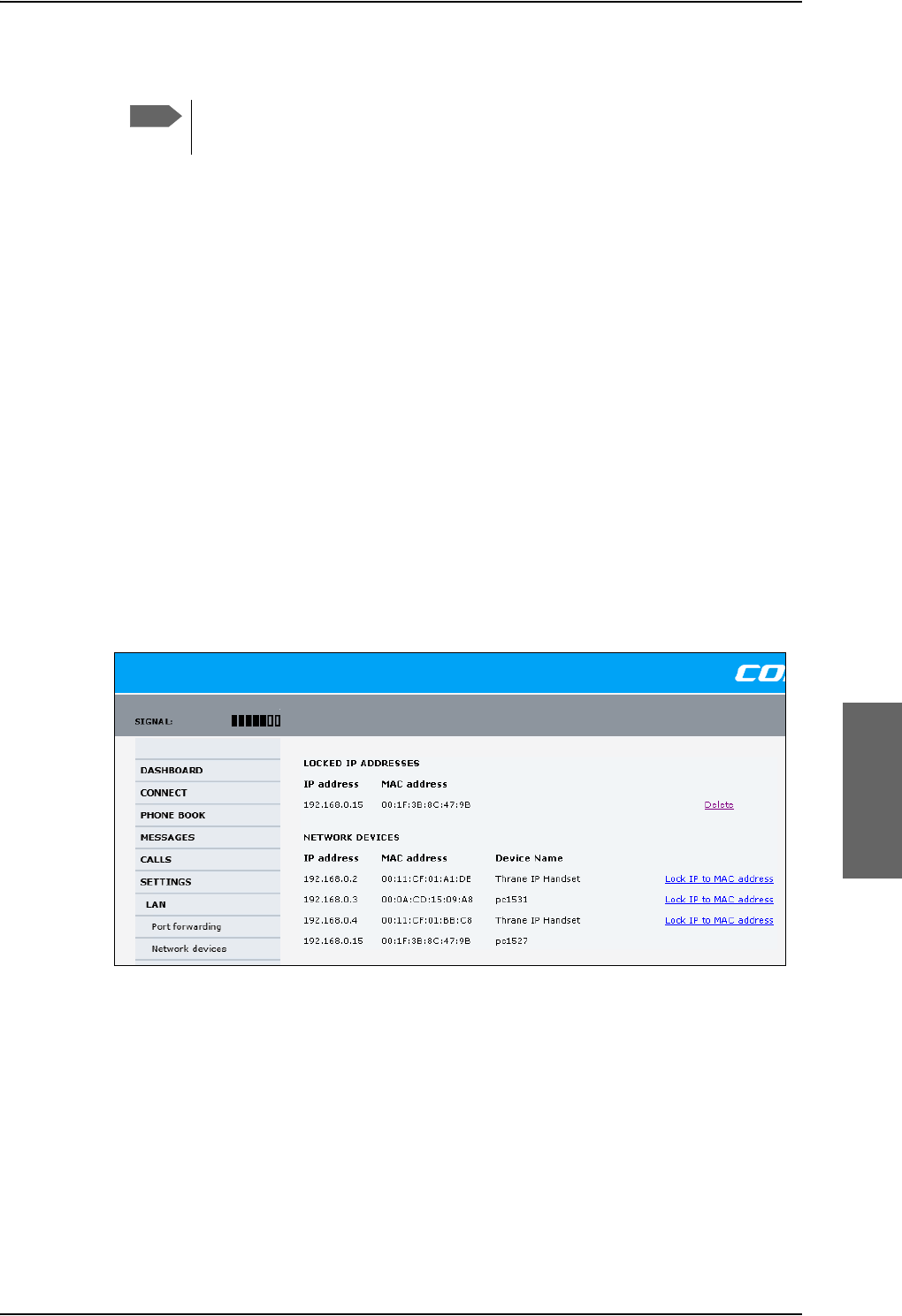
To manage LAN/WLAN network users
98-124743-F Chapter 6: Configure the AVIATOR 700 system 6-59
To select more than one secondary profile, press and hold Ctrl or Shift while selecting.
The Context Identifiers (CIDs) for the selected primary and secondary profiles are listed
under Profile CIDs.
13. Click Apply.
Note that changes to the status and the Internet connection type of a network user group
first take effect after rebooting the AVIATOR 700 SBU.
6.8.3 Manage network devices
Overview
A network device, in this context, is an Ethernet hardware device, identified by its unique
MAC address.
When a network device with dynamic IP address is connected to the SBU, it is
automatically listed in the Network devices list.
View the list of network devices
To view the list of network devices, select SETTINGS > LAN > Network devices. All
network devices that have been connected to the SBU are listed here.
Figure 6-45: Web interface: Settings, LAN, Network devices
Note
If you have selected both a primary and one or more secondary profiles you
must define a traffic flow filter before you can establish a valid connection.

To manage LAN/WLAN network users
6-60 Chapter 6: Configure the AVIATOR 700 system 98-124743-F
Lock an IP address to a MAC address
When the device is locked to an IP address, the SBU will always assign this IP address to the
device with this MAC address (if DHCP is enabled and the Internet connection is in Router
mode, and not a Bridge mode connection).
To lock an IP address to a MAC address, do as follows:
1. If prompted, log in as an administrator. The default user name and password are admin
and 1234.
2. To lock a device to its current IP address, click the link next to the device. The device is
then locked to the current IP address and added to the list of locked IP addresses at the
top of the page.
3. To unlock a device from the IP address, click Delete next to the device in the LOCKED
IP ADDRESSES list.
6.8.4 The network classification table
Overview
The network classification table is used to define which network devices, IP addresses
and/or LAN ports are associated with which network user groups.
Each entry in the table shows MAC address, IP address, LAN port and network user group.
When a network device is connected, the SBU runs through the network classification table
to check if the new connection matches MAC address, IP address and LAN port in any of
the entries in the table. When a match is found, the SBU establishes a PDP context with the
settings of the network user group assigned in the matching entry. The device is now ready
for use with the SBU.
Add or edit an entry in the network classification table
The network classification table shows which devices are associated with which LAN ports
and network user groups. An Asterisk (*) is a “wild card”, meaning that any value is accepted.
You can add, edit and delete entries in the network classification table.
To add a new entry to the table or to edit an existing entry, do as follows:
1. If prompted, log in as an administrator. The default user name and password are admin
and 1234.
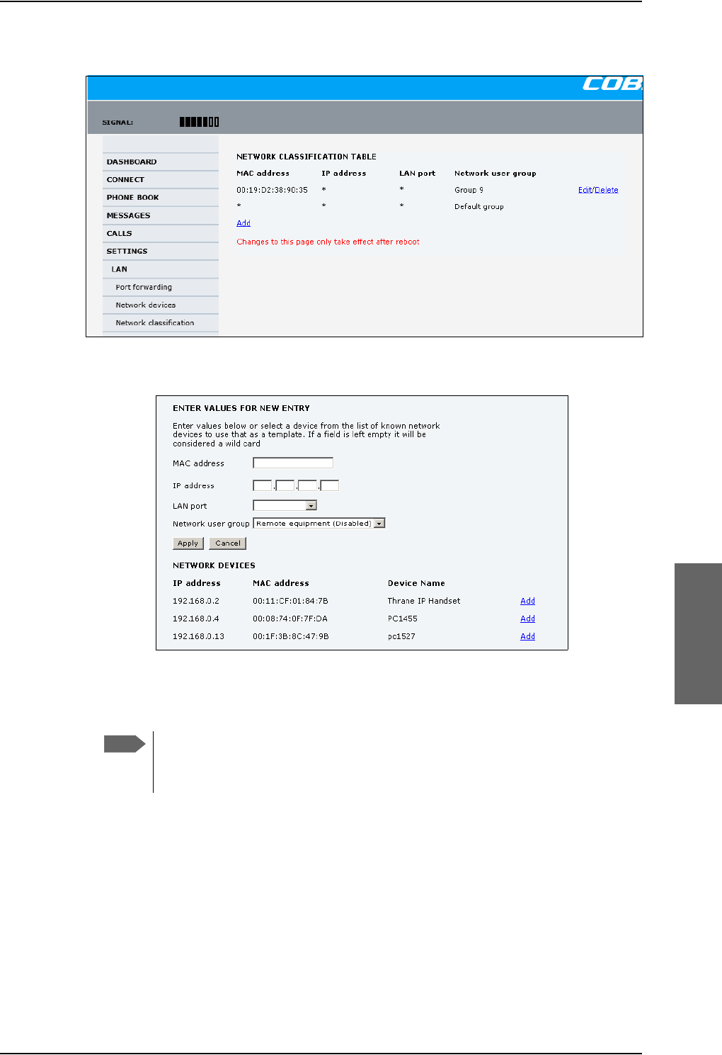
To manage LAN/WLAN network users
98-124743-F Chapter 6: Configure the AVIATOR 700 system 6-61
2. Select SETTINGS > LAN > Network classification.
Figure 6-46: Web interface: Settings, LAN, Network classification table
3. Click Edit next to the entry you want to edit, or click Add at the bottom of the list.
Figure 6-47: Web interface: Settings, LAN, Network classification table, Edit or Add
4. Click Add next to a network device you want to use, or type in the MAC address
manually at the top of the page.
If you leave a field empty, it is the same as a “wild card” and it will be shown as
an Asterisk in the Network classification table. Unless you are using a Static IP
address, the IP address field should always be left empty.
5. Select the LAN port and Network user group you want to associate with the device.
Network user groups are created and defined in the Network user group page. See Set
up the network user groups on page 6-55.
6. Click Apply.
Note

To manage LAN/WLAN network users
6-62 Chapter 6: Configure the AVIATOR 700 system 98-124743-F
Change the priority in the network classification table
Connections are evaluated in the order they are listed. The first entry (and only the first
entry) that matches the properties of the connected device is applied, meaning that the
connection will be using the settings of the network user group assigned to that entry.
To change the priority of an entry, click the up or down arrow next to the entry.
Figure 6-48: Web interface: Settings, LAN, Network classification table, change priority
The Default network user group is always last, so it is only used if none of the other entries
match the properties of the connected device.
Remove an entry in the network classification table
In the network classification table, click Delete next to the entry you want to delete.
6.8.5 Definitions for network terms
Header compression
The header of a data packet contains control information belonging to that specific packet.
The information in the header can take up a considerable amount of bandwidth. In order to
use the bandwidth more efficiently, you can enable Header Compression, meaning the
header information is compressed, leaving some of the information out. With disabled
header compression the full header ist transmitted with each data packet. This takes up
bandwidth and means a more reliable data transmission with less data loss.
You can select whether or not to use Header Compression for your data transmission.
•Header Compression enabled: More efficient use of the bandwidth available,
recommended typically for Internet, e-mail, ftp applications etc.
•Header Compression disabled: More reliable data transmission. Recommended for
time-critical applications like VoIP and streaming applications, as well as other
applications where packet loss is to be minimized.
If there are problems with packet loss you might want to disable header compression and
see whether the header compression is the reason for the packet loss.
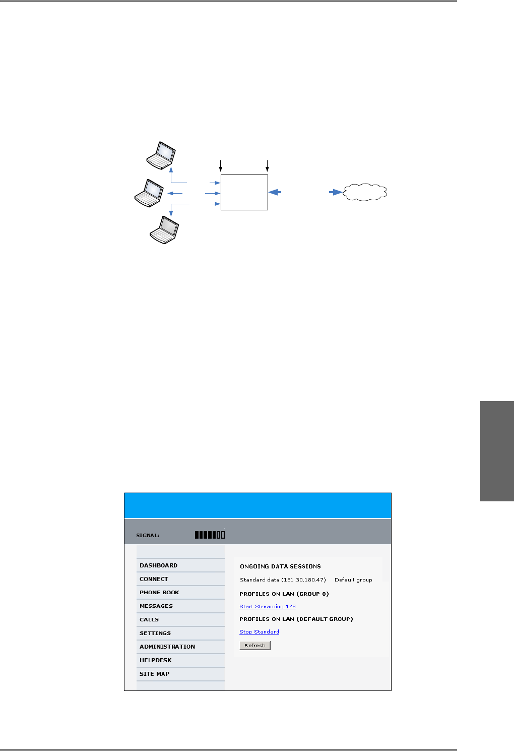
To manage LAN/WLAN network users
98-124743-F Chapter 6: Configure the AVIATOR 700 system 6-63
6.8.6 NAT (Network Address Translation)
NAT enables a local-area network to use one set of private IP addresses for internal traffic
and an assigned or static IP address for external traffic. The built-in NAT module in the SBU
makes all necessary address translations between the local-area traffic and the external
traffic.
Figure 6-49: NAT (Network Address Translation)
If more than one user is connected, you must select a network user group with Router
mode to use the NAT functionality of the SBU.
6.8.7 Start and stop any data session
The administrator can start and stop data sessions for all network user groups connected to
the SBU.
To start or stop a data session, do as follows:
1. Select CONNECT.
If prompted, enter the administrator user name and password. The default user name is
admin and the default password is 1234.
Under ONGOING DATA SESSIONS at the top you can see which data sessions are
currently active.
$
%
&
7HUPLQDO
ZLWK1$7
7UDIILF$
7UDIILF&
7UDIILF$%DQG&
7UDIILF%
3ULYDWH
,3DGGUHVVHV
IRU$%DQG&
$VVLJQHGRU
VWDWLF
,3DGGUHVV
,QWHUQHW
/RFDODUHD ([WHUQDO
Figure 6-50: Web interface: Connect, to start and stop data sessions (example)
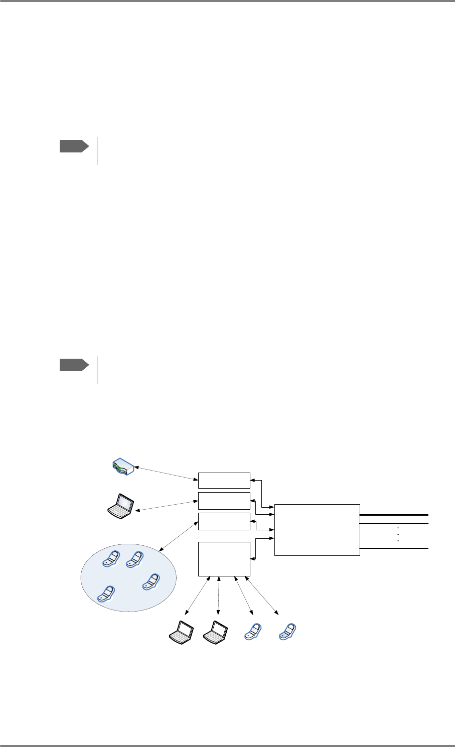
To manage LAN/WLAN network users
6-64 Chapter 6: Configure the AVIATOR 700 system 98-124743-F
In the example above you can manually start the Streaming 128 connection of
GROUP 0 and stop the Standard connection of the DEFAULT GROUP.
2. Click on the session you want to start or stop.
3. Click Refresh to update the current state of the connection(s). Note that there might
be some latency when updating the connection status, you might have to wait and click
Refresh again to update the Dashboard to the current state.
The PDP context for the data session is not activated before any unit in the LAN
tries to communicate, e.g. sends a DHCP request.
6.8.8 Establish a PPPoE connection
Overview
You can establish a Point-to-Point-over-Ethernet (PPPoE) connection to the BGAN network
using the AVIATOR 700 system. Use this connection type if you want to control start and
stop of the connection independently from the built-in web interface of the SBU.
Possible applications for this type of connection are as follows:
• Connecting a router
• Connecting broadcast equipment, optionally through a PC
• Establishing a Picocell for the use of cell phones
Without the built-in Router option the AVIATOR 700 system is limited to one
PPPoE connection.
The following drawing shows how the PPPoE connection and the built-in web interface
handle connections to the SwiftBroadband network.
Figure 6-51: Example for PPPoE connections
Note
Note
6%8
3'3&RQWH[WXSWR
6ZLIW%URDGEDQG
QHWZRUN
%XLOWLQ
ZHE
LQWHUIDFH
333R(
FRQQHFWLRQ
3&DQGRUEURDGFDVWHTXLSPHQW
8VHU3&
$SSOLFDWLRQV
IRU333R(
+DQGOLQJFRQQHFWLRQ
WRWKH%*$1WHUPLQDO
$VVLJQLQJFRQQHFWLRQ
3'3FRQWH[WWRJRRXW
RQWKH6ZLIW%URDGEDQG
QHWZRUN
5RXWHU
3LFRFHOO
333R(
FRQQHFWLRQ
8VHU3&
333R(
FRQQHFWLRQ
:LUH
+DQGVHW
,3
+DQGVHW
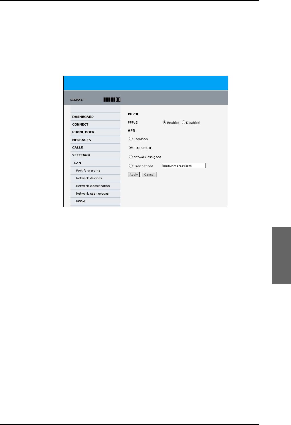
To manage LAN/WLAN network users
98-124743-F Chapter 6: Configure the AVIATOR 700 system 6-65
Enable PPPoE network connections in the AVIATOR 700 system
During the configuration of the system you can configure whether the system should allow
and handle PPPoE network connections.
To enable or disable the system to support PPPoE network connections do as follows:
1. Select SETTINGS > LAN > PPPoE
Figure 6-52: Web interface, Settings, LAN, PPPoE
2. Select Enabled or Disabled (default).
3. Check with your airtime provider what your APN is and select accordingly.
4. Click Apply to send the settings to the terminal.
How to configure the connected PC, router or other equipment
You must configure the equipment correctly to establish a network connection using
PPPoE. How to set up a new network connection depends on the type of equipment, refer
to the user documentation of the equipment.
You need the following parameters:
•User name and password
The user name and password can be left blank. Then the registration on the APN is most
commonly done in a way that the data connection will be established with a dynamic
IP address from the airtime provider.
To request a static IP (if subscribed to) from the APN you must type in the user name
and password from your airtime subscription.
Note for MAC OS: User name and password are required. Use user name void and
password void. This works for some ISPs. Contact your airtime provider for further
information.
• For setups that have a check box for Enable LCP extensions, deselect this.

To manage LAN/WLAN network users
6-66 Chapter 6: Configure the AVIATOR 700 system 98-124743-F
•Service name: For certain services, i.e. a streaming class, you must type in a specified
text string when asked for a service name. The following table shows the service names
and descriptions that are supported by the terminal.
PPPoE setup with a non-default APN
You can set up a network connection using PPPoE for another APN than the default APN.
Check the documentation from the Service provider for the new APN name. Enter the
following commands in the field Service name when setting up the network connection:
Table 6-5: PPPoE connection, service names and descriptions for custom APN
Service name for custom APN Description
XBBa
a. For SwiftBroadband the part of the service name “XBB” can be replaced by “SBB”.
:AT+CGDCONT=1,ip,”<APN name>”;
+CGEQREQ=1,3
Standard IP data connection
XBB:AT+CGDCONT=1,ip,”<APN name>”;
+CGEQREQ=1,1,8,8,8,8,2,0,“0E0”,”0E0”,3,0,0
Streaming IP data connection
8 kbps
XBB:AT+CGDCONT=1,ip,”<APN name>”;
+CGEQREQ=1,1,16,16,16,16,2,0,“0E0”,”0E0”,3,0,0
Streaming IP data connection
16 kbps
XBB:AT+CGDCONT=1,ip,”<APN name>”;
+CGEQREQ=1,1,32,32,32,32,2,0,“0E0”,”0E0”,3,0,0
Streaming IP data connection
32 kbps
XBB:AT+CGDCONT=1,ip,”<APN name>”;
+CGEQREQ=1,1,64,64,64,64,2,0,“0E0”,”0E0”,3,0,0
Streaming IP data connection
64 kbps
XBB:AT+CGDCONT=1,ip,”<APN name>”;
+CGEQREQ=1,1,128,128,128,128,2,0,“0E0”,”0E0”,3,0,0
streaming IP data connection
128 kbps
XBB:AT+CGDCONT=1,ip,”<APN name>”;
+CGEQREQ=1,1,512,512,512,512,2,0,“0E0”,”0E0”,3,0,0
streaming IP data connection
X-Stream
Service name Description
Blank default, primary standard IP data connection
XBBa:BACKGROUND
a. For SwiftBroadband the part of the service name “XBB” can be replaced by “SBB”.
default, primary standard IP data connection
XBB:STREAM8K primary streaming IP data connection 8 kbps
XBB:STREAM16K primary streaming IP data connection 16 kbps
XBB:STREAM32K primary streaming IP data connection 32 kbps
XBB:STREAM64K primary streaming IP data connection 64 kbps
XBB:STREAM128K primary streaming IP data connection 128 kbps
XBB:X-STREAM primary streaming IP data connection up to 512 kbps.
Table 6-4: PPPoE connection, service names and descriptions
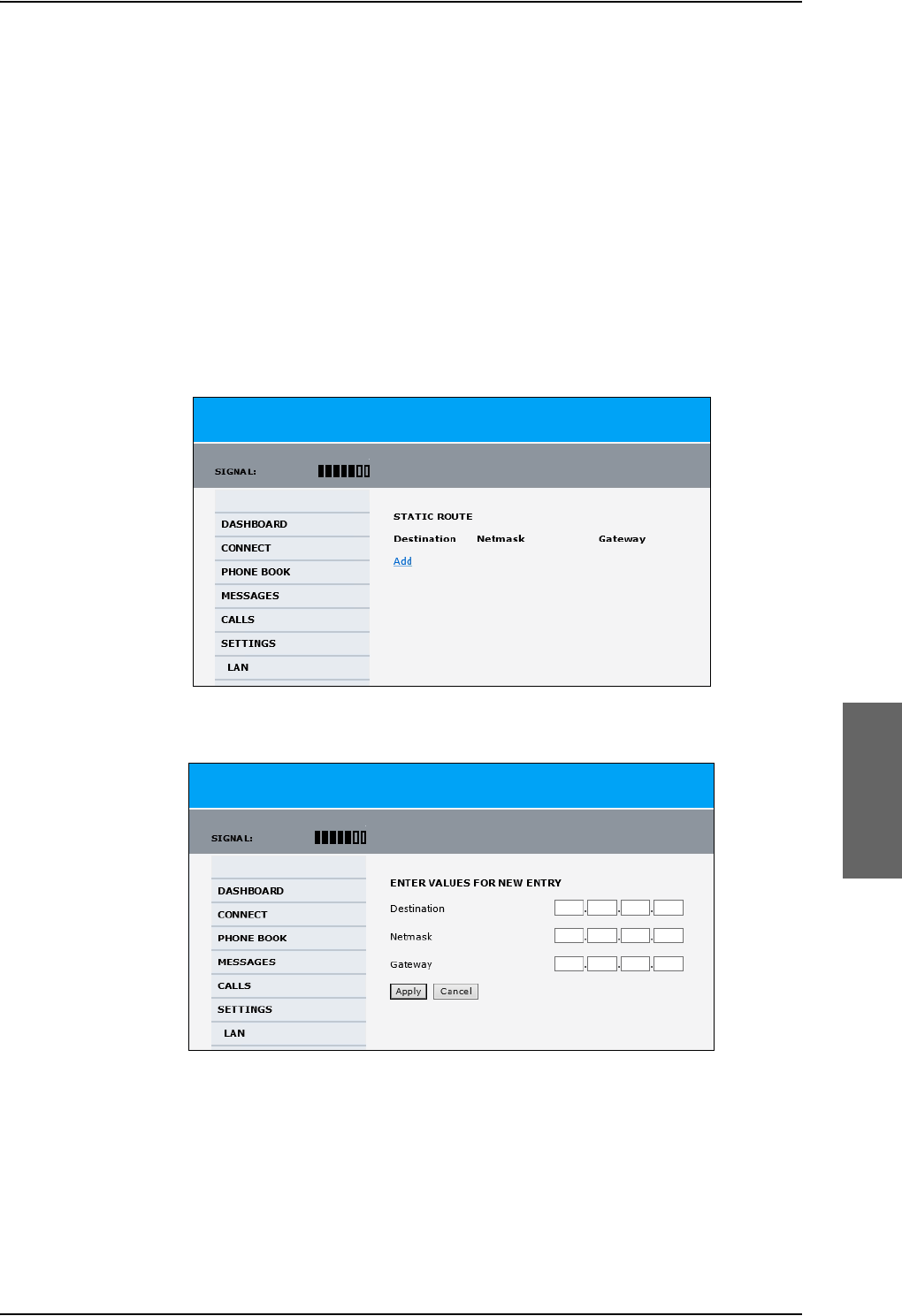
To manage LAN/WLAN network users
98-124743-F Chapter 6: Configure the AVIATOR 700 system 6-67
Example: To set up a standard background data connection using the APN
“bgan.inmarsat.com” enter:
XBB:AT+CGDCONT=1,ip,”bgan.inmarsat.com”;+CGEQREQ=1,3
For more information about the command syntax see the standard 3GPP TS 27.007.
6.8.9 To set up static routing
When you have an external gateway connected to your SBU, the SBU is not automatically
able to “see” the network on the other side of the gateway. However, you can set up your
SBU to communicate with a device on the other side of a gateway, by using Static routing.
To set up a new device for static routing, do as follows:
1. Select SETTINGS > LAN > Static route.
Figure 6-53: Web interface, Settings, LAN, Static route
2. Click Add.
Figure 6-54: Web interface, Settings, LAN, Static route, add
3. Enter the values for your device.
• Destination: The IP address you want to route to.
• Netmask: The netmask you want to route to.
• Gateway: The gateway, e.g. the address of a wireless access point or router to which
the destination device is connected.

Administration of the SBU
6-68 Chapter 6: Configure the AVIATOR 700 system 98-124743-F
4. Click Apply.
The values for the new entry are now in the list. This means that the SBU can
communicate with the destination IP address on the other side of the gateway.
6.8.10 SNMP interface
You can connect equipment to perform SNMP queries on the SBU in order to retrieve
configuration and present settings.
Contact AVIATOR.support@cobham.com to obtain the MIB files.
6.9 Administration of the SBU
In this section of the web interface you can configure a number of administrative settings:
•Access the administration settings
•Save and load a configuration
•Call charges
•Log handling
•Data limits
•To use profiles
•To use traffic flow filters
•SIM card access protection: SIM PIN and SIM Lock
•Set up user permissions
•Remote management
•Remote activation of a connection using SMS
•Link monitoring (SwiftBroadband only)
•Restricted dialing
•Multi-voice (option)
6.9.1 Protect the SBU against unintended configuration changes
You can protect the SBU against unintended changes of the setup:
1. Change the administrator password from user name: admin and password: 1234 to a
user name and password of your choice. For further details see Change the
administrator password on page 6-70.
2. You can deny non-administrator users access to certain functions and make the
respective pages in the web interface read-only. For further details see Set up user
permissions on page 6-84.
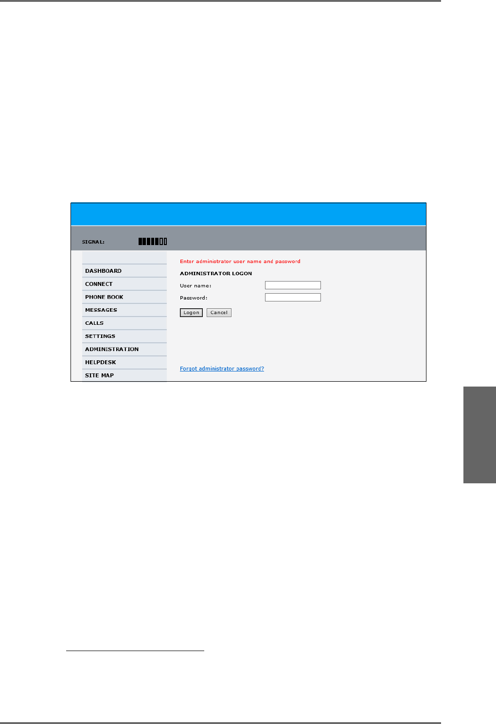
Administration of the SBU
98-124743-F Chapter 6: Configure the AVIATOR 700 system 6-69
6.9.2 Access the administration settings
Log on as administrator
The Administration settings require an Administration user name and password. You must
also login as an administrator in the sections for SETTINGS, LAN, Network Devices,
Network classification, Network user groups and PPPoE.
To log on as administrator, do as follows:
1. Select ADMINISTRATION from the left navigation pane.
2. Enter the Administration user name and password.
The default user name is admin and the default password is 1234.
If you have forgotten the administrator password, you can reset the password by
clicking the link at the bottom of the page.1 For further information, see the next
section Reset the administrator password.
3. Click Logon.
The Administration page is now updated to let you change the user name and
password, Save/load a configuration or log off Administration.
Figure 6-55: Web interface: Administration
1. The link is only shown when the PC is connected to the Maintenance connector on the SBU
front plate.
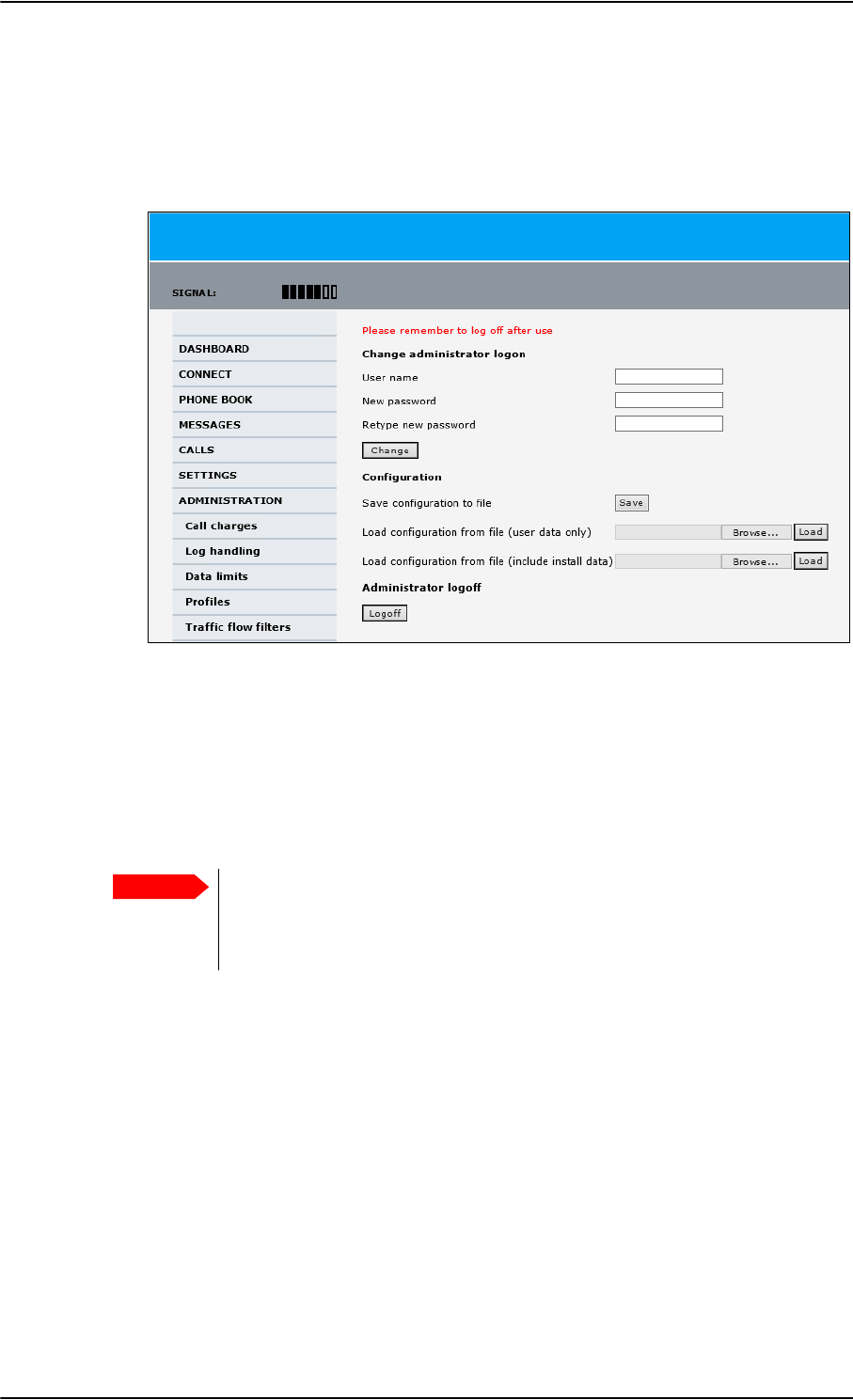
Administration of the SBU
6-70 Chapter 6: Configure the AVIATOR 700 system 98-124743-F
Change the administrator password
To change the administrator password, do as follows:
1. After entering the administrator user name and password in the ADMINISTRATION
page, locate the section Change administrator logon.
Figure 6-56: Web interface: Administration, change administrator logon
2. Type in the existing user name.
3. Type in the new password and retype it on the next line.
4. Click Change. At the next logon the new password is required.
Reset the administrator password
If you have forgotten and need to reset the administrator password, do as follows:
1. Contact your supplier for a reset code.
Report the serial number and IMEI number of the terminal.
You find the serial number and IMEI number in the Dashboard.
Important
To reset the administrator password you must connect the PC to the
Maintenance connector on the SBU front plate. If not, the link Forgot
administrator password? on the ADMINISTRATOR LOGON page will not
be visible.
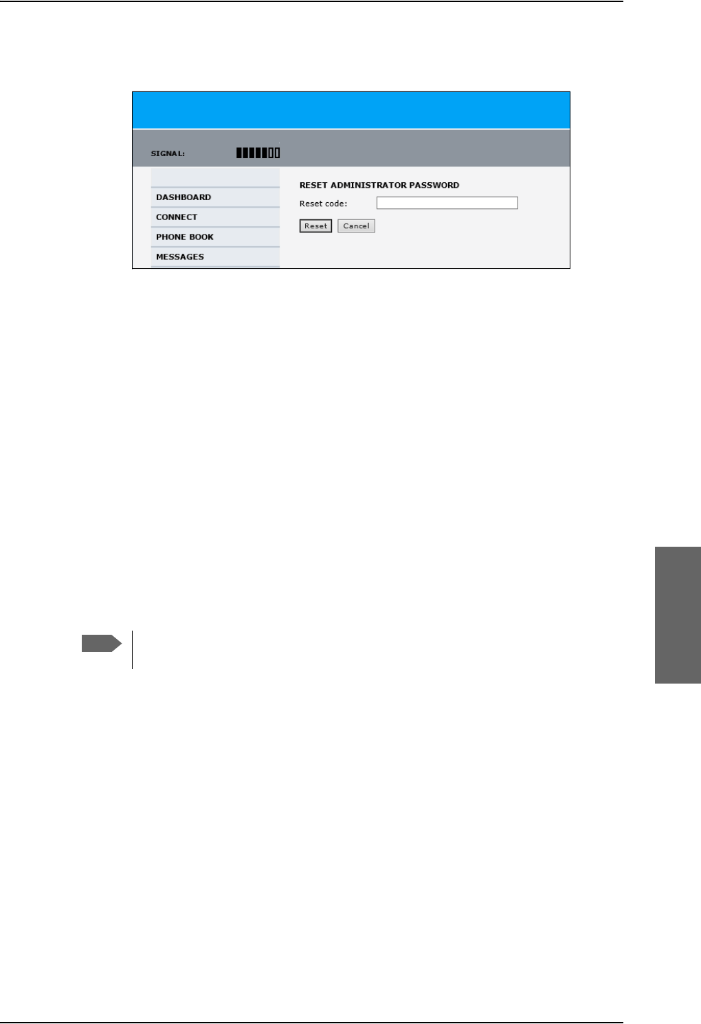
Administration of the SBU
98-124743-F Chapter 6: Configure the AVIATOR 700 system 6-71
2. Click the link Forgot administrator password? at the bottom of the
ADMINISTRATOR LOGON page (see the previous section).
Figure 6-57: Web interface: Administration, Reset administrator password
3. Type in the reset code obtained from your supplier and click Reset.
4. Type in the user name Admin and the default password 1234.
5. Click Logon.
For information on how to change the password, see the next section Change the
administrator password.
Log off administration
If you have not entered anything for 30 minutes under ADMINISTRATION, you are logged
off automatically. To log off manually, click Logoff under administrator logoff in the
ADMINISTRATION page.
6.9.3 Save and load a configuration
If you need to reuse a configuration in another SBU, you can save the current configuration
to a file, which can then be loaded into the other SBU. You can also use this feature for
backup purposes.
Configuration files can only be exchanged between SBUs with the same
software version!
Save a configuration to a file
The settings from the following pages of the web interface are saved in the configuration
file:
•SETTINGS
• ADMINISTRATION
• PHONE BOOK
Note
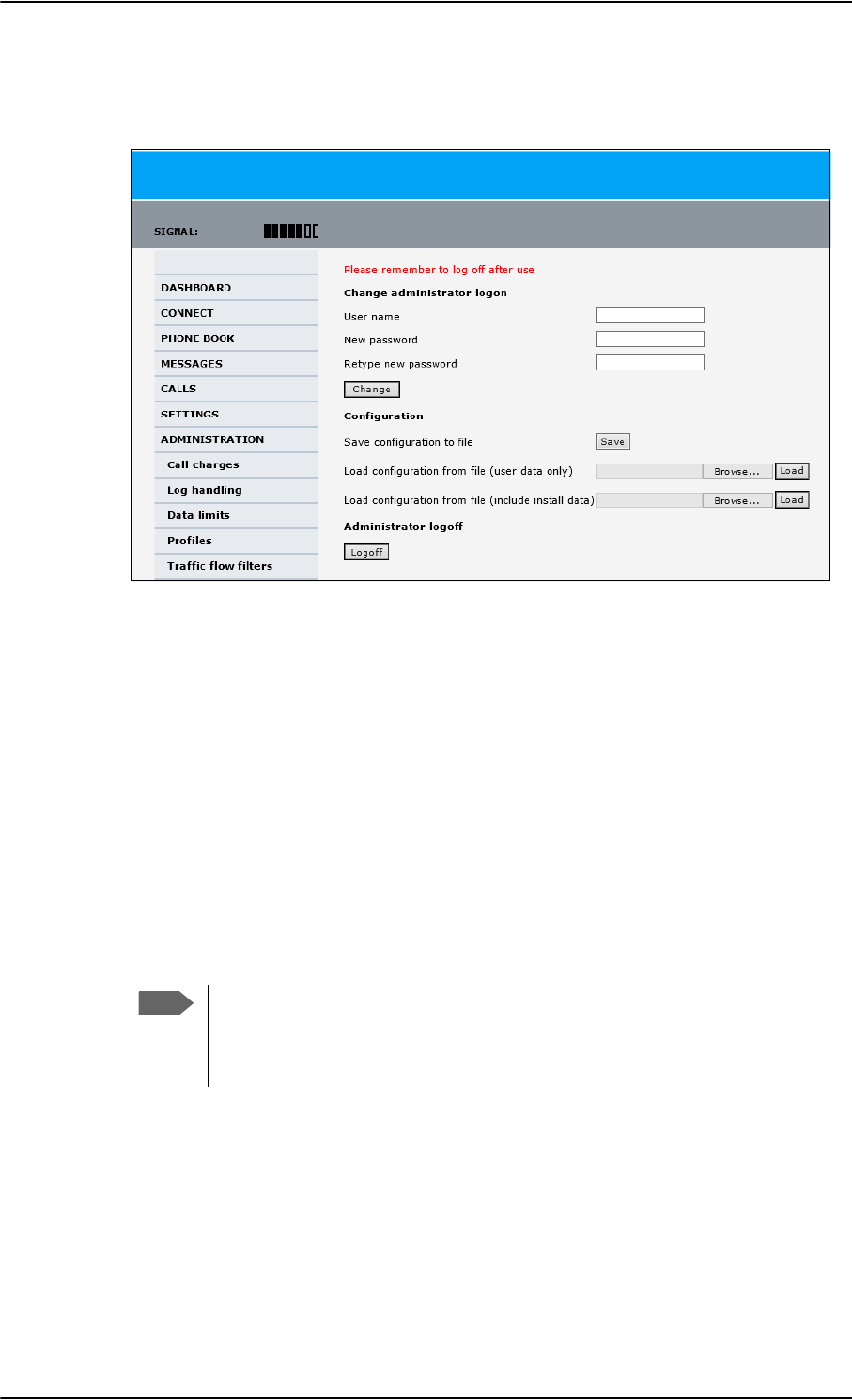
Administration of the SBU
6-72 Chapter 6: Configure the AVIATOR 700 system 98-124743-F
To save your current configuration to a file, do as follows:
1. In the ADMINISTRATION page, under Configuration, click Save.
Figure 6-58: Web interface: Administration, saving a configuration file
2. Accept the default destination file name or type in the destination file name and
location.
3. Click OK. The configuration is now saved to a file. This file is used to load the
configuration into another SBU.
Load a configuration from a file
In this example the PC is connected to the SBU front maintenance connector. To load a
configuration from a file, do as follows:
1. In the ADMINISTRATION page, under Configuration, select the upload type:
•Load configuration from file (include install data), available when connected
to the SBU front maintenance connector.
The install data are the pages Discrete I/O, RF settings and External systems.
Note
This feature can only be used with systems of the same system type, for
example one AVIATOR 700 SBU to another AVIATOR 700 SBU. To use this
upload type the PC must be connected to the SBU front maintenance
connector.
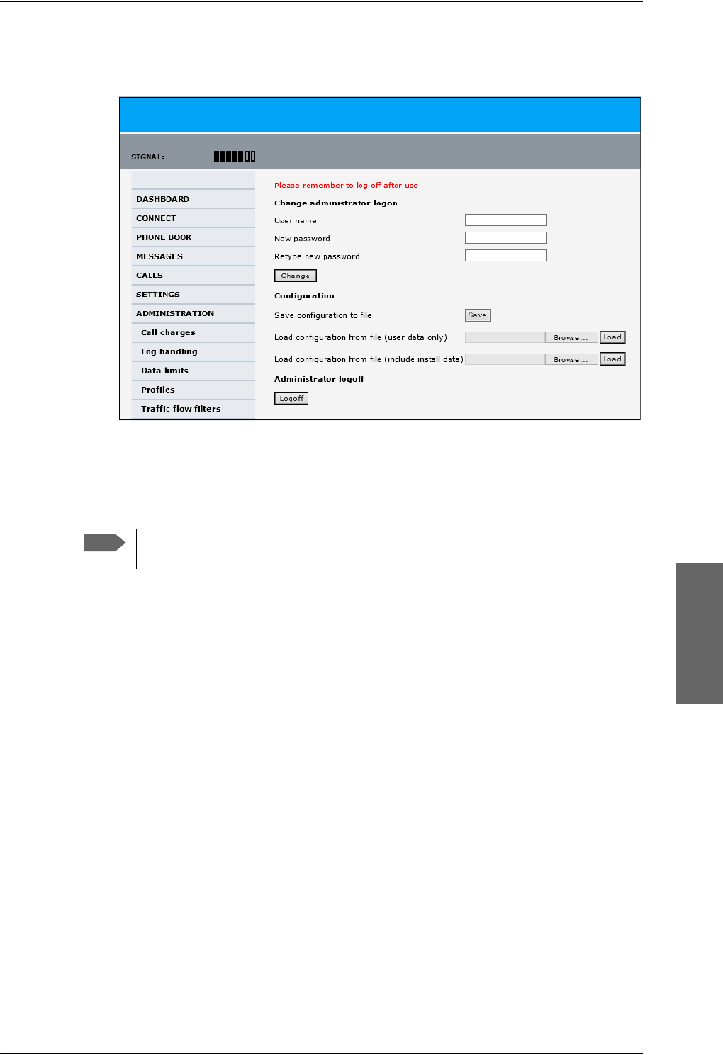
Administration of the SBU
98-124743-F Chapter 6: Configure the AVIATOR 700 system 6-73
•Load configuration from file (user data only). This upload type is available on
any other LAN/WLAN interface of the SBU.
2. Click Browse... to browse to the file you want to import. Then click Open.
3. Click Load.
The new configuration is now loaded into your SBU.
4. Restart the SBU to activate the new configuration.
Figure 6-59: Web interface: Administration, saving a configuration file
Note
Configuration files can only be exchanged between SBUs with the same
software version!
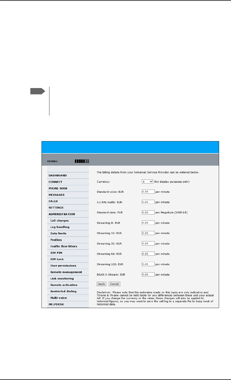
Administration of the SBU
6-74 Chapter 6: Configure the AVIATOR 700 system 98-124743-F
6.9.4 Call charges
In this section you can enter the call charges so you at all times can see the current charges
for the services used. Consult the documentation from your service provider for the
subscribed services, then enter these tariffs in the web interface. The system automatically
calculates the charges for your calls and data sessions. The entered tariffs are used for
estimating the charges for calls and data sessions. The estimated charge is listed for each
call or data session in the call log. For further information, see the AVIATOR 700 user
manual.
To enter the call tariffs, do as follows:
1. From the left navigation pane, select ADMINISTRATION > Call Charges.
Figure 6-60: Web interface: Administration, Call Charges
2. Select the currency from the Currency drop-down list.
3. Enter the tariff for each of the services.
4. Click Apply.
Note
Thrane & Thrane does not take responsibility for the correctness of the estimated
charges. This calculation is only a rough estimate of the charge, based on the tariff
entered by the user. Also, the Airtime Provider may have different methods of
calculating the charge.
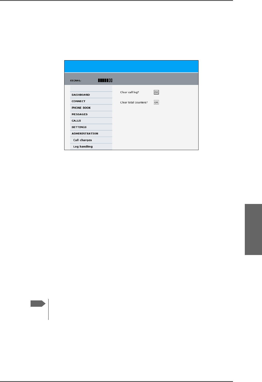
Administration of the SBU
98-124743-F Chapter 6: Configure the AVIATOR 700 system 6-75
6.9.5 Log handling
To clear the logs of the SBU and/or reset the counters for the time connected, do as
follows:
1. From the left navigation pane in the ADMINISTRATION page, select Log Handling.
Figure 6-61: Web interface: Administration, Log Handling
2. To clear the Call log, click OK next to Clear call log?.
3. To clear the total counters, click OK next to Clear total counters?.
This will reset the Time connected counters on the Calls page.
6.9.6 Data limits
You can set a limit for the use of data services that can be downloaded over the AVIATOR
700 system. You either specify a maximum number of MB for the standard data
connection, and/or a time interval from start to end for a streaming connection.
For a detailed description how to access the SBU from a remote location see the AVIATOR
700 user manual.
6.9.7 To use profiles
The profiles are used in the network user groups. You select one or several profiles when
setting up a network user group. You need an administrator password to define profiles and
traffic flow filters.
Together with traffic flow filters the profiles are used as a tool to manage the traffic flow.
If you have selected more than one profile (one primary and one or more
secondary profiles) for an interface, you must define traffic flow filter(s) before
you can establish a valid connection.
What is a profile?
A profile is a collection of Quality of Service (QoS) settings and other settings defining the
mode in which data is transmitted on an interface. For example, a profile is used to define
whether the connection is a Streaming connection or a Standard connection.
Note
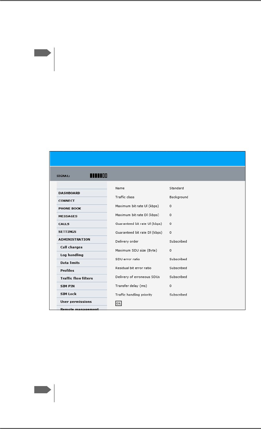
Administration of the SBU
6-76 Chapter 6: Configure the AVIATOR 700 system 98-124743-F
You can select between a number of predefined profiles or define your own profiles for
your data transmission. For further information on profiles, refer to the 3GPP standard TS
23.107 “Quality of Service (QoS) concept and architecture”.
If no traffic flow filters are defined, the Primary profile for a network user group is
used for all traffic from that network user group. Then the secondary profile will
not become active.
To learn more about traffic flow filters see What are traffic flow filters? in the next section.
Select the profiles for a network user group
When you set up a network user group, you typically select one of the predefined profiles
to use as a Primary profile for that network user group. You select optionally one or more
Secondary profiles.
For further information on how to select the profiles, see To manage LAN/WLAN network
users on page 6-54.
You typically do not need to define new profiles, the predefined profiles cover the most
common applications. You can customize a user profile and set-up several user-defined
profiles.
Define new profiles
When you define your profiles you can select Subscribed for many of the settings. If you
select Subscribed, the value given in your Airtime subscription is automatically used.
For AVIATOR 700, the maximum Streaming bit rate is the X-Stream service
(up to approximately 450 kbps).
Note
Figure 6-62: Web interface, Administration, Profiles, Example: Standard
Note
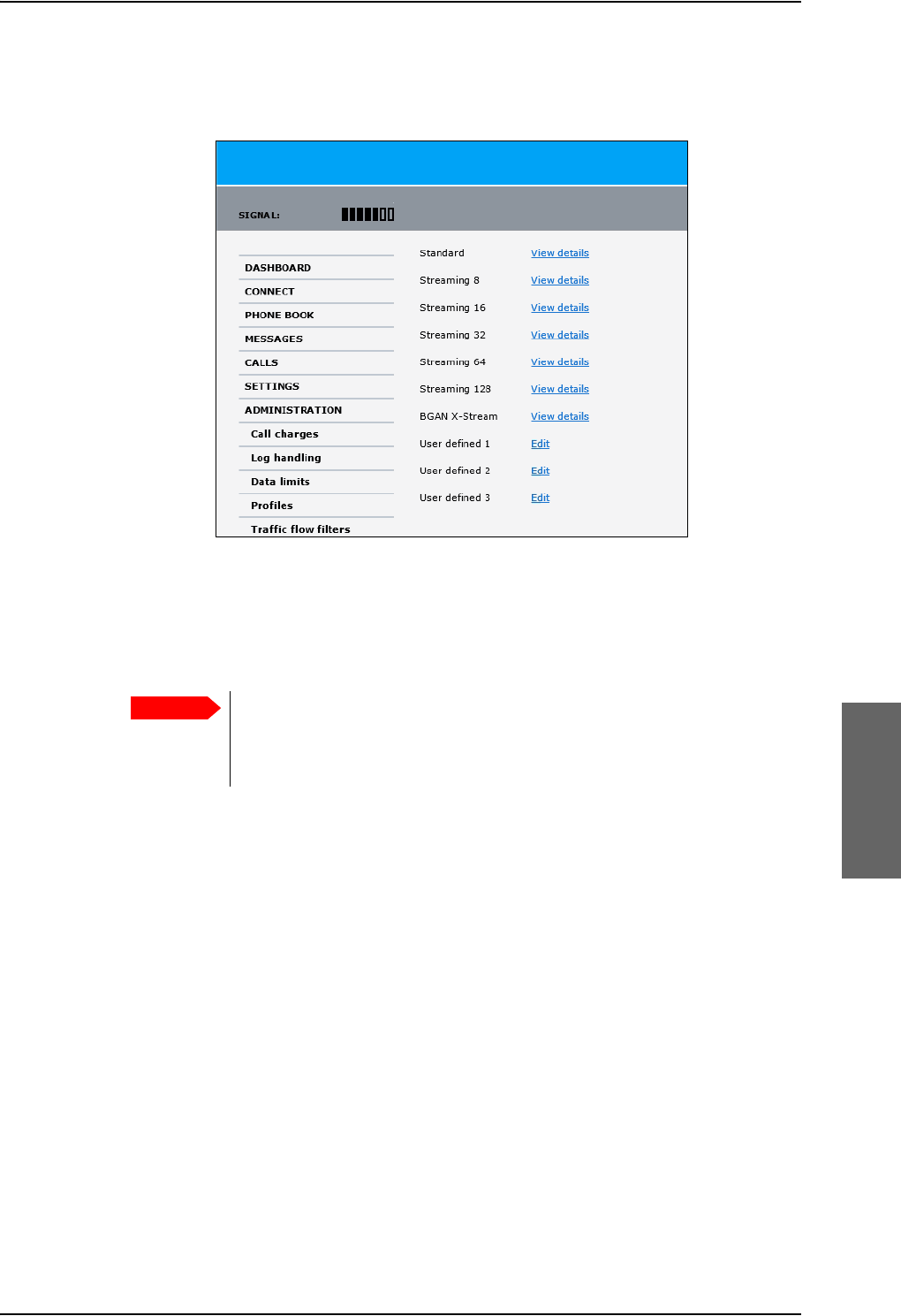
Administration of the SBU
98-124743-F Chapter 6: Configure the AVIATOR 700 system 6-77
To define a new profile, do as follows:
1. From the left navigation pane, select ADMINISTRATION > Profiles.
Figure 6-63: Web interface. Administration, Profiles, select profile
2. Click Edit for the profile you want to define.
3. Fill in the top field with the name for your profile.
4. In the Traffic class row of your new profile, select a class from the drop-down list.
You may select one of the following:
•Conversational is real-time two-way conversation. It is primarily used for voice
over IP and video conferences.
•Streaming is real-time one-way communication. It is primarily used for video and
audio.
•Interactive is two-way communication (not real-time). It is used for
communication that is not very delay-sensitive, such as web browsing, data base
retrieval and server access. Examples of machines interaction with remote
equipment are: polling for measurement records and automatic data base enquiries
(tele-machines).
•Background is used for data which is not delay-sensitive, such as E-mail, SMS,
download of databases and reception of measurement records.
5. Type in the bit rates in kbps in the following rows:
•Maximum bit rate Ul (kbps) is the maximum upload bit rate allowed for this
profile.
•Maximum bit rate Dl (kbps) is the maximum download bit rate allowed for this
profile.
Important
For best performance, choose the right traffic class for your application. In
general, Standard IP (Background) is best suited for TCP/IP applications,
e.g. web browsing, e-mail, file transfer, VPN. Streaming IP is best suited for
UDP traffic, e.g. live video or audio.

Administration of the SBU
6-78 Chapter 6: Configure the AVIATOR 700 system 98-124743-F
•Guaranteed bit rate Ul (kbps) is the guaranteed upload bit rate needed for this
profile.
•Guaranteed bit rate Dl (kbps) is the guaranteed download bit rate needed for this
profile.
6. In the Delivery order row, select from the scroll list whether or not data should be
delivered in the same order it was sent.
•Yes means the data packets are delivered in the same order they were sent.
7. In the Maximum SDU size (byte) row, type in the maximum allowed packet size in
Bytes (rounded off to nearest 10). The maximum packet size possible is 1520.
8. In the Delivery of erroneous SDUs row, select one of the following from the list:
•Yes means packets are allowed to contain errors. This setting is suitable for delay-
sensitive transmission, because the need for retransmission is limited. The SDU Error
settings in step 9 and step 10 will apply.
•No means packets are not allowed to contain errors, and the SDU Error setting in
step 9 will not be applied. This setting is suitable where error-free transmission is
important and delays are accepted.
•No detect means that errors will not be detected, and the SDU Error setting in step
9 will not be applied.
9. If you selected Yes in step 8, select from the SDU error ratio drop-down list the
fraction of a packet allowed to be lost or erroneous.
10. Select from the Residual bit error ratio drop-down list the undetected bit error ratio
of a packet. If no error detection is requested, Residual bit error ratio indicates the bit
error ratio in the delivered packets.
11. In the Transfer delay (ms) row, type in the delay in ms. This is the delay from the time
data is received in the SBU until it arrives at the receiving end.
• If the Transfer delay is 500 ms, error correction is disabled.
• If the Transfer delay is 4000 ms, error correction is applied.
12. In the Traffic handling priority row, select from the drop-down list which priority
this connection should have.
13. Click Apply.
The new profile is now added, and can be selected from the lists of primary and
secondary profiles when you set up your interfaces.
Note
When you click Apply, the bit rate values you typed in may be rounded off
because only certain values are allowed.
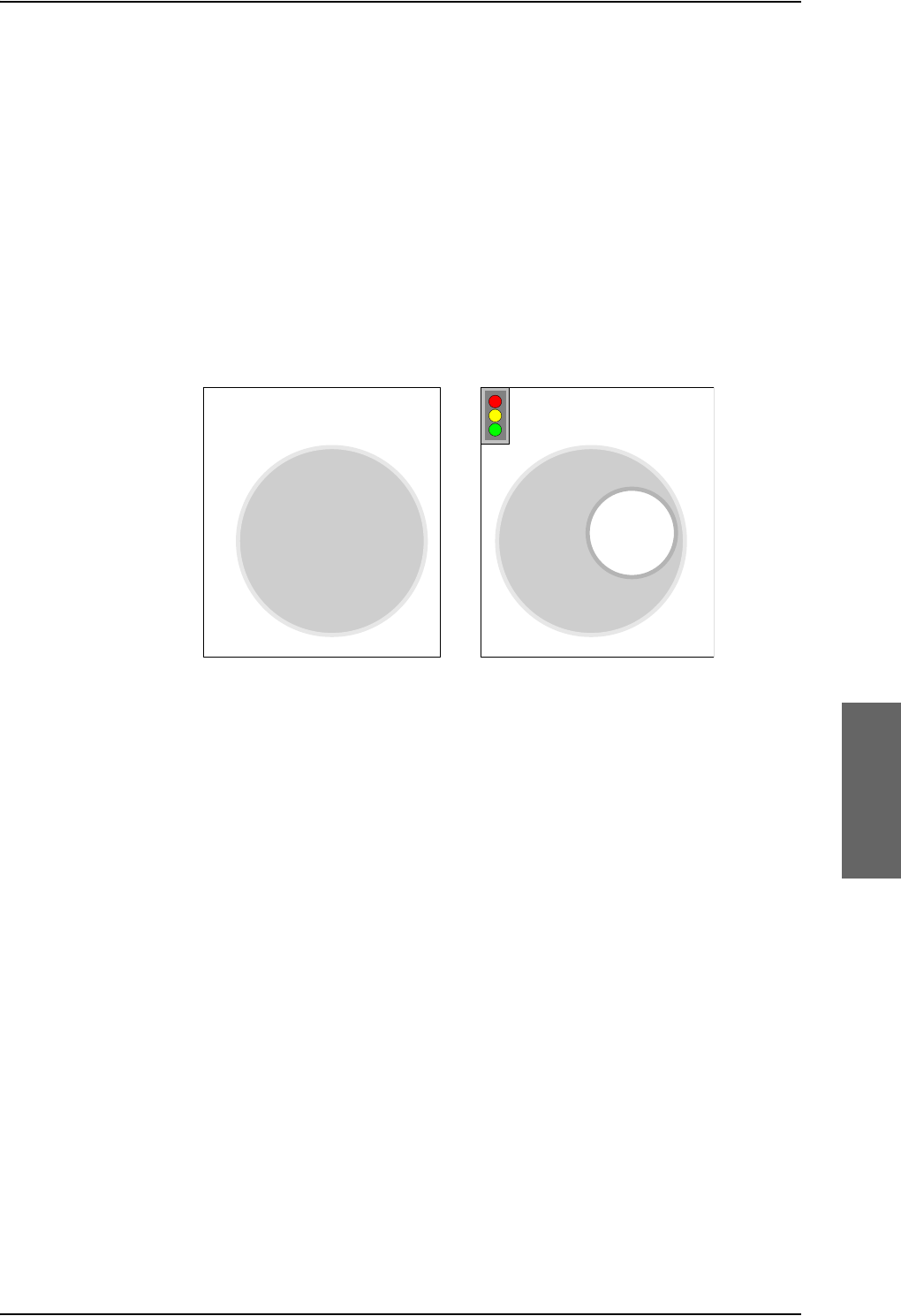
Administration of the SBU
98-124743-F Chapter 6: Configure the AVIATOR 700 system 6-79
6.9.8 To use traffic flow filters
Purpose of the traffic flow filters
The purpose of the traffic flow filters is to assign different priorities to different types of
traffic, in order to optimize performance.
Example: When you are browsing the Internet, a Standard IP connection is normally
sufficient. However, to have a video conference you may need a Streaming IP
connection in order to obtain a direct connection without interruptions. Your
traffic flow filters can define these priorities, so that your connection
automatically switches to Streaming e.g. when you have a video conference.
Note that you have to activate a streaming connection in the web interface.
What are traffic flow filters?
When more than one type of traffic is needed, you must use both a primary and one or
more secondary profiles. A traffic flow filter provides preferred treatment of a data packet.
The traffic flow filter classifies data packets for the BGAN core network and the SBU
received from the external network into the proper profile.
You can define up to eight traffic flow filters. Each packet filter has an evaluation
precedence index that is unique within all traffic flow filters associated with the profiles
that share the same PDP (Packet Data Protocol) address. The evaluation precedence index
determines the order in which the filters are applied; 0 is applied first, then 1 and so forth.
Information of source, destination, type of service etc. is combined in each packet filter in
the list.
Figure 6-64: Traffic flow filters to filter traffic types
6WDQGDUG,3
FRQQHFWLRQ
NESV
WRWDOGDWD
UDWH
6WDQGDUG,3
FRQQHFWLRQ
6WUHDPLQJ,3
FRQQHFWLRQ
NESV
NESV
WRWDOGDWD
UDWH
W\SHRIWUDIILF SURILOH
QRWUDIILFIORZILOWHUQHHGHG
W\SHVRIWUDIILF SURILOHV
WUDIILFIORZILOWHUQHHGHG
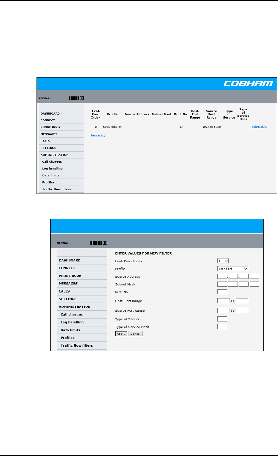
Administration of the SBU
6-80 Chapter 6: Configure the AVIATOR 700 system 98-124743-F
Define traffic flow filters
To define the traffic flow filters, do as follows:
1. From the left navigation pane, select
ADMINISTRATION > Traffic flow filters. The example below shows one traffic
flow filter.
2. Click the link New entry.
Figure 6-66: Web interface: Administration, Traffic flow filters, New entry
3. Select a number in the Eval.Prec. Index drop-down list.
The evaluation precedence index defines the order in which the traffic flow filters are
applied to packets. 0 is first, then 1, 2 etc.
4. Select the Profile from the drop-down list.
The available profiles are the profiles listed under ADMINISTRATION > Profiles. The
selected profile is applied to all traffic that matches the conditions entered in step 5.
Figure 6-65: Web interface: Administration, Traffic flow filters
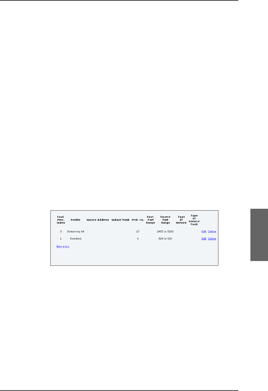
Administration of the SBU
98-124743-F Chapter 6: Configure the AVIATOR 700 system 6-81
5. Fill in one or more of the following fields to define the filter.
The allowed ranges appear in hover text when you pass the mouse over the fields.
•Source address + Subnet mask.
This is an IPv4 IP address and subnet mask. Only packets received from the specified
source are accepted by the filter.
•Protocol number.
This is uniquely assigned for the protocol being used. For TCP (typically Internet, e-
mail, FTP) set this to 6, for UDP (typically streaming) to 17. The protocol number
determines which protocol is used by the traffic flow filter.
•Destination port range (From and To). This parameter requires knowledge of ports
being used by the selected applications. Note that Source and Destination are
relative to the BGAN core network. This means that Destination is your SBU.
•Source port range (From and To). This parameter requires knowledge of ports
being used by the selected applications. Note that you must fill in both From and To,
even if there is only one port.
•Type of Service + Type of Service mask.
Set this value to a number between 0 and 255.
Type of Service (TOS) is an 8-bit field in a packet header, with associated mask, that is
used to define Quality of Service.
For further information on the principles and parameters of the traffic flow filters, refer
to the 3GPP standards TS27.007 V4.2.0 and TS 23.060 V4.7.0.
6. Click Apply at the bottom of the page.
Example of a list of traffic flow filters
Below is an example of a list with two traffic flow filters.
Figure 6-67: Web interface: Example of two traffic flow filters
In this example, data packets are filtered in the following order:
1. The filter with evaluation precedence index 0 checks for UDP packets (protocol number
17), in the port range 2455-5000. When these packets are identified, they are assigned
a 64 kbps Streaming channel (the Streaming 64 profile).
2. The filter with evaluation precedence index 1 checks remaining packets for TCP packets
(protocol number 6), on port 524. These packets are routed to the standard IP
connection (the Standard profile).
3. Remaining traffic is routed to the standard IP connection.
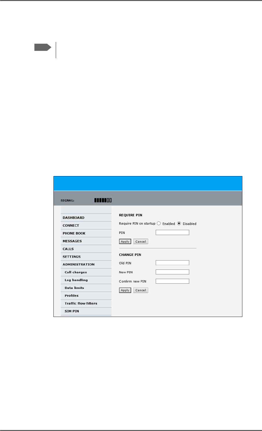
Administration of the SBU
6-82 Chapter 6: Configure the AVIATOR 700 system 98-124743-F
6.9.9 SIM card access protection: SIM PIN and SIM Lock
SIM PIN
To avoid unauthorized use of the system you can enable the SIM PIN. Then the user has to
enter the SIM PIN before being able to use the system. The SIM PIN is disabled per default.
You enable the SIM PIN in the web interface. You can also specify a new SIM PIN in the
web interface. To do this you have to enter the original SIM PIN and then specify a new
one.
To manage the SIM PIN of the terminal do as follows:
1. From the left navigation pane, select ADMINSTRATION > SIM PIN.
2. If you want to protect the system with a system SIM PIN select Enabled.
3. You can enter a new PIN or change the existing PIN.
4. Click Apply to save the changes.
Figure 6-68: Web interface, Administration, SIM PIN
Note
There is typically no SIM PIN needed for the AVIATOR 700 system. The following
functions might apply for special airtime subscriptions that have a SIM PIN.
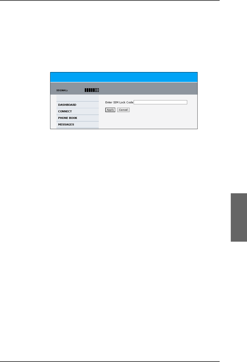
Administration of the SBU
98-124743-F Chapter 6: Configure the AVIATOR 700 system 6-83
SIM Lock
The supplier may lock the SIM card of the terminal to a specific service provider. For further
information contact your supplier. To unlock the SIM lock of the SIM card from your
airtime provider do as follows:
1. From the left navigation pane, select ADMINSTRATION > SIM LOCK.
2. Enter the SIM Lock Code and click Apply.
Figure 6-69: Web interface, Administration, SIM LOCK
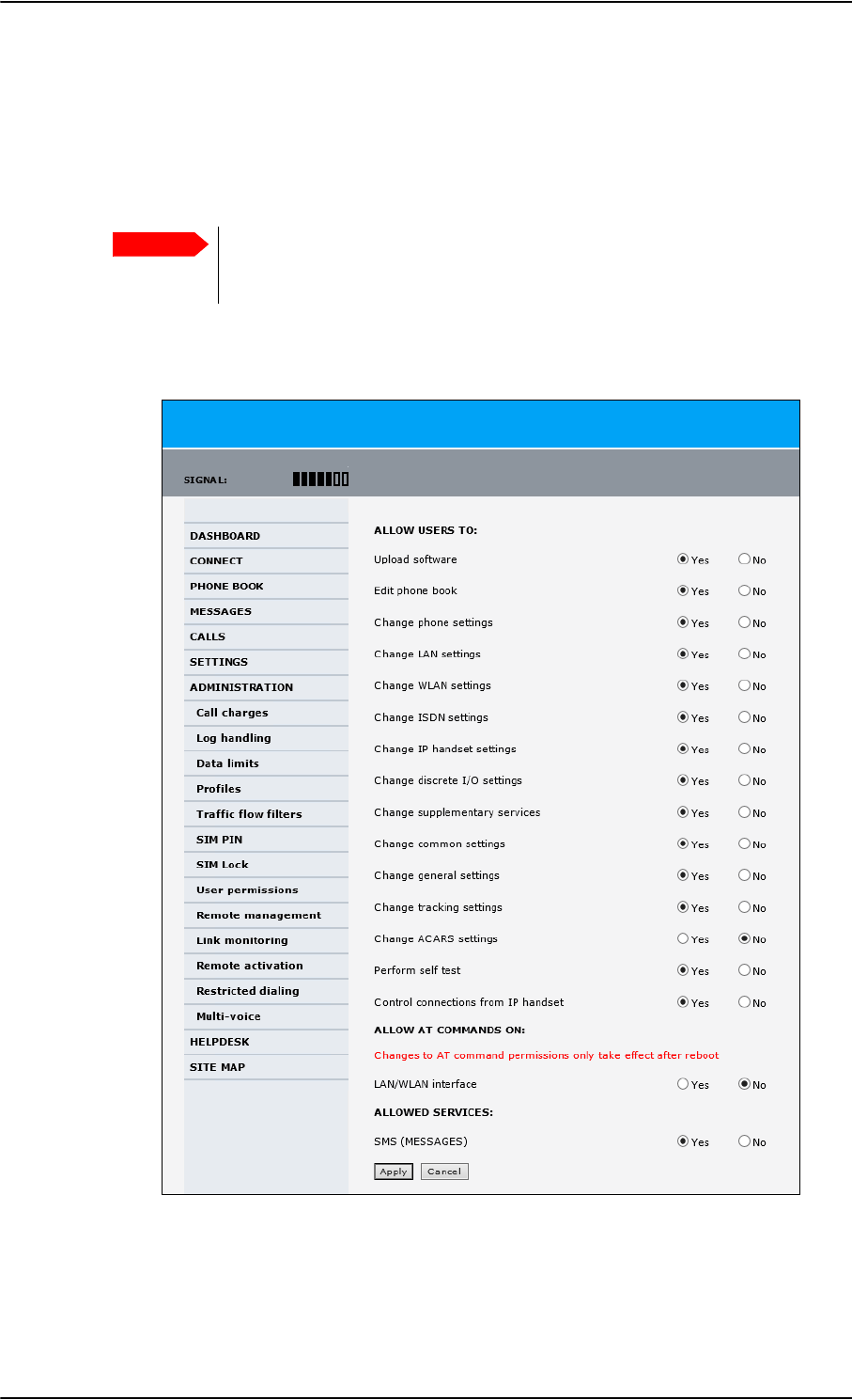
Administration of the SBU
6-84 Chapter 6: Configure the AVIATOR 700 system 98-124743-F
6.9.10 Set up user permissions
You can manage user access to certain functions of the AVIATOR 700 system. You can
allow or deny users that are not administrators access to certain functions and make these
pages read-only. This is useful if you want to protect the system against unintended
changes or tampering of the system.
Protect the SBU against unintended change of setup. We recommend to
study the following screen thoroughly and decide which areas of the
AVIATOR 700 system you want to give non-administrator users access to.
To set up the user permissions, do as follows:
1. From the left navigation pane, select ADMINISTRATION > User permissions.
Figure 6-70: Web interface: Administration, User permissions
2. For each item under ALLOW USERS TO:, select
•Yes to allow access
Important

Administration of the SBU
98-124743-F Chapter 6: Configure the AVIATOR 700 system 6-85
•No to block access to the settings. Then the pages are read-only for non-
administrators. The settings on the page cannot be changed.
3. Under ALLOW AT COMMANDS ON: select
•Yes to allow the use of AT commands on the LAN/WLAN interface
•No to block the use of AT commands on the LAN/WLAN interface
AT commands are typically used during maintenance and service.
4. Under ALLOWED SERVICES select:
•Yes to allow that the user can send and receive text messages
•No to block sending and receiving text messages. Note that the menu item
MESSAGES is not displayed any longer.
5. Click Apply.
The settings to which access is denied are now greyed out for the non-administrator
user.
Note
This setting does not take effect until the SBU is restarted.
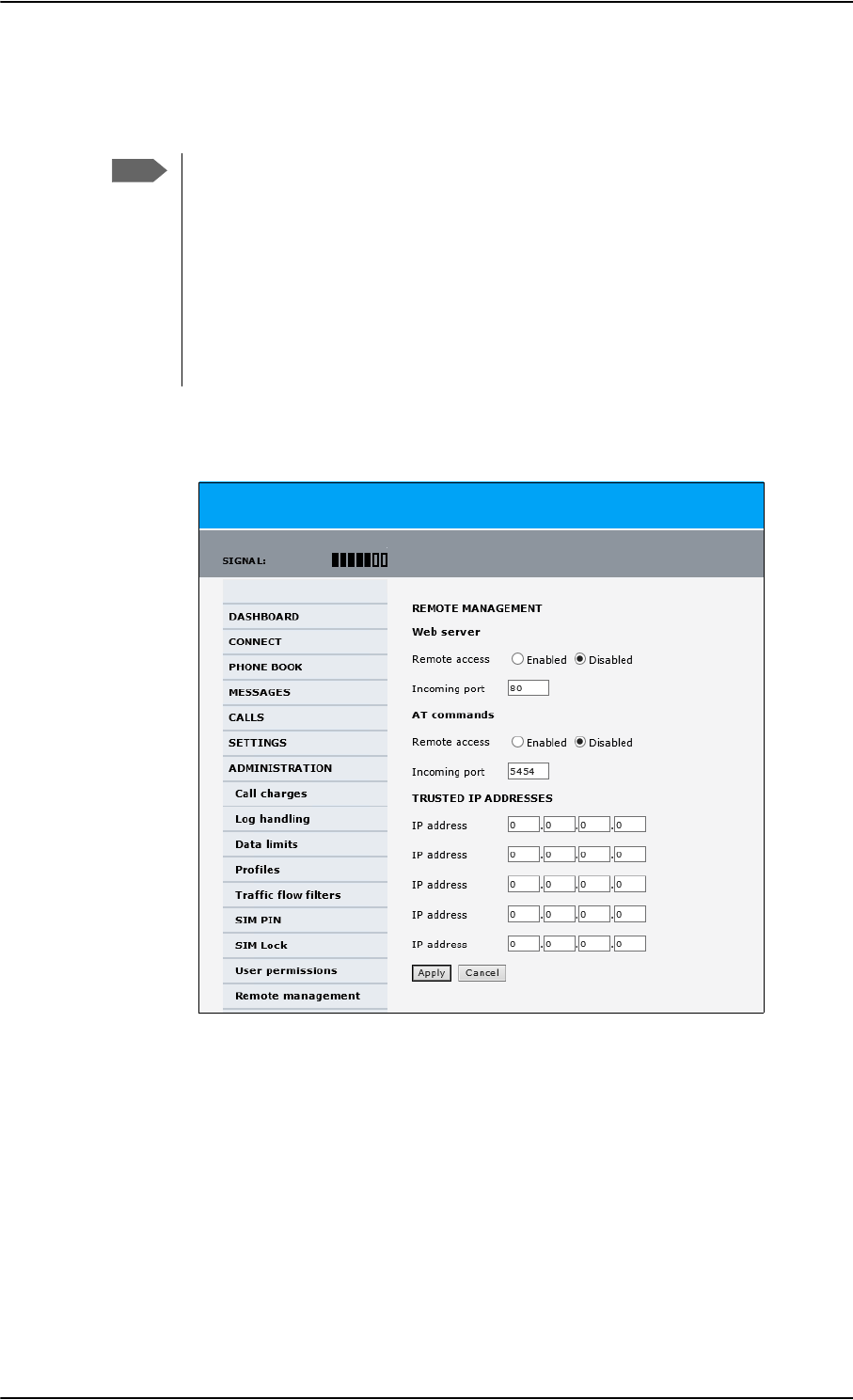
Administration of the SBU
6-86 Chapter 6: Configure the AVIATOR 700 system 98-124743-F
6.9.11 Remote management
You can set up the SBU for control from a remote location.
If you want to remotely control the SBU, it must have activated a connection. This
can be done in several ways:
• Automatic activation of a Standard data connection, see step 10 on page 6-58
in Edit a network user group.
• Manual start of a data connection (Standard data or Streaming, see Start or
stop a standard data connection on page 6-24)
•Remote start of a data connection with an SMS, see Remote activation of a
connection using SMS on page 6-87.
To set up the SBU for remote management, do as follows:
1. From the left navigation pane, select ADMINISTRATION > Remote management.
Figure 6-71: Web interface: Administration, Remote management
2. Select whether remote access using a web server should be Enabled or Disabled and
enter the Incoming port number.
3. Select whether AT commands should be Enabled or Disabled and enter the
Incoming port number.
4. Under TRUSTED IP ADDRESSES, type in the IP addresses of the devices you want to
give access to the SBU.
5. Click Apply to save the new settings.
You can now access the SBU from one of the trusted IP addresses, using the incoming port
defined in the Incoming port field.
Note
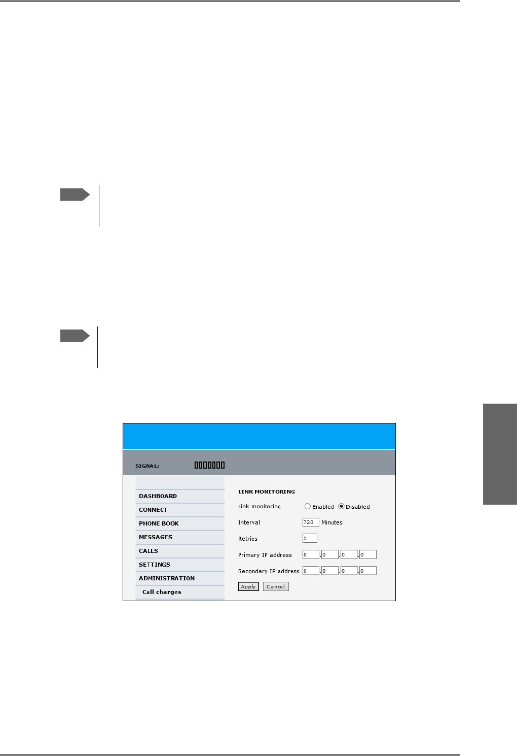
Administration of the SBU
98-124743-F Chapter 6: Configure the AVIATOR 700 system 6-87
For a detailed description how to access the SBU from a remote location see the AVIATOR
700 user manual.
6.9.12 Remote activation of a connection using SMS
If you want to remotely control the SBU, it must have activated a connection. You can do
this by sending an SMS to the SBU. The SBU must be powered up and logged on to the
satellite services to receive the SMS and then start the connection.
For a detailed description how to activate a connection using SMS see the AVIATOR 700
user manual.
The SBU must be logged on to the satellite services to receive and accept an
activation SMS. If the SMS is considered too old or sent before the SBU has been
switched on and has logged on, the SMS will be ignored.
6.9.13 Link monitoring (SwiftBroadband only)
You can monitor the external SwiftBroadband IP connection of the AVIATOR system using
the link monitoring feature. With this feature activated, the terminal will send out ping
commands (ICMP Echo Requests) to a server of your choice.
To set up link monitoring, do as follows:
1. From the left navigation pane, select ADMINISTRATION > Link monitoring.
2. Select Enabled if you want to enable Link monitoring.
3. Select the Interval between each ping.
4. Select the number of Retries before the terminal reboots.
5. Type in the Primary and optionally the Secondary IP address.
This is the IP address of the server(s) to which the terminal will send ping commands.
Note
Note
Link monitoring is only performed on data connections with the Default network
user group (see Set up the network user groups on page 6-55). This data
connection must be activated before link monitoring can start.
Figure 6-72: Web interface: Administration, Link monitoring

Administration of the SBU
6-88 Chapter 6: Configure the AVIATOR 700 system 98-124743-F
6. Click Apply.
When a data session is started with the Default network user group, the terminal will start
sending ping commands to the Primary IP address the number of times specified at
Retries. If no response is received, it will send the same number of ping commands to the
Secondary IP address, if available. If no response is received here either, the terminal will
reboot.
6.9.14 Restricted dialing
In order to manage the use of the AVIATOR 700 system efficiently you can set up the SBU
to limit all calls to allowed numbers or numbers in the phone book. This feature can be
enabled for each connected handset separately.
For a detailed description how to restrict dialing see the AVIATOR 700 user manual.
6.9.15 Multi-voice (option)
You can subscribe to Multi-voice with or without additional numbers. Multi-voice is
disabled per default.
You must have Multi-voice in your airtime subscription, AVIATOR Wireless
Handset software version minimum 1.03 and SBU software version minimum
AVIATOR 700 (Level E): 1.07, AVIATOR 700D (Level D): 2.01, in order to support
the Multi-voice function.
To enable Multi-voice, do as follows:
1. Enter the web interface of your terminal.
2. Select Administration > Multi-voice.
3. Select Multi-voice.
If you want to use an external PBX, select Using external Multi-voice PBX and
select the interface used to connect the PBX to the terminal
You are now ready to use Multi-voice. For more detailed information about configuring
Multi-voice see Configure Multi-voice on page 6-92.
Rules for concurrent calls (without cockpit reserve)
• First call initiated: You can use any connected handset and any call type for incoming as
well as outgoing calls.
• Second and subsequent calls: You can only use handsets connected to the WLAN
interface for calls initiated/received while another call is active. The call type for the
second and subsequent calls is always Standard Voice.
Note
Use a server that is reliable and that supports and responds to ICMP Echo
Requests.
Note
Note
If you have additional numbers in your airtime subscription, you must set up how
the system should use them. See the sections Handset contexts on page 6-89.

Administration of the SBU
98-124743-F Chapter 6: Configure the AVIATOR 700 system 6-89
Additional numbers for Multi-voice
In addition to the phone numbers for incoming Standard Voice, and 3.1 kHz Audio and
UDI/RDI, your subscription may include extra phone numbers that can be assigned to
specific handsets. If you want to use the additional phone numbers in your subscription,
you must set up the following in the web interface:
• Enable the use of additional numbers in the web interface under ADMINISTRATION >
Multi-voice. See Configure Multi-voice on page 6-92.
• Add the additional numbers from your airtime subscription under PHONE BOOK >
MOBILE NUMBERS > ADDITIONAL NUMBERS.
• Assign the numbers to handsets. Depending on the handset interface you want to use,
see the pages SETTINGS > Phone/Fax, SETTINGS > ISDN or SETTINGS > IP
handsets in the web interface.
Check with your service provider for individual billing of an additional number.
Handset contexts
Calls to the SBU are treated differently depending on the handset context. If additional
numbers are used, there are 3 possible handset contexts, which are explained in this
section:
•Call type groups
•Directly assigned handsets
•Unassigned handsets
Call type groups
The handsets are called using one of the mobile numbers for either Standard Voice or
3.1 kHz audio. All handsets in a group will ring when the belonging number is called.
For information on how to associate a handset with a group, see
•Set the call types for AVIATOR Wireless Handsets on page 6-46
•Configure the Phone/Fax interface (2-Wire) of the SBU on page 6-34
•Configure the ISDN interface of the SBU on page 6-35
Note
You must have Multi-voice with additional numbers in your airtime subscription to
be able to use this feature.
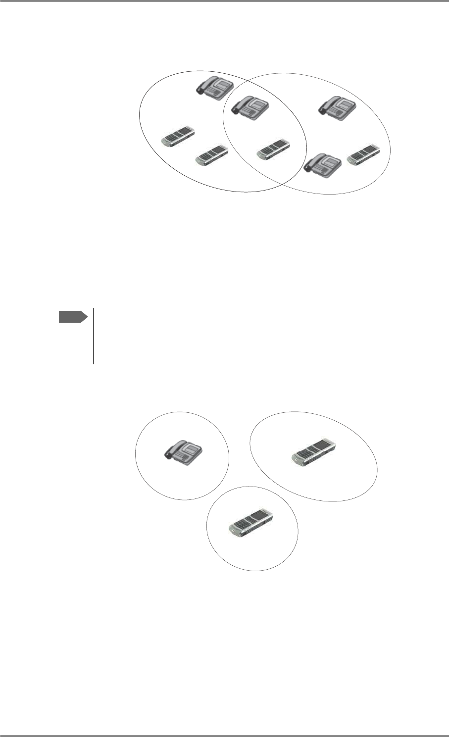
Administration of the SBU
6-90 Chapter 6: Configure the AVIATOR 700 system 98-124743-F
Directly assigned handsets
The mobile numbers are assigned to individual handsets. Only the assigned handset will ring
when the associated number is called.
For information on how to assign a number to a handset, see the pages SETTINGS >
Phone/Fax, SETTINGS > ISDN or SETTINGS > IP handsets in the web interface.
Note that you can also assign the call type numbers directly (in the example above, the
Standard Voice number is assigned to IP handset number 0501). If you do so, be aware that
only the assigned handset can receive a call to this number. The handset connected to the
Phone port 1 and the IP handset no. 0502 are each assigned an additional number.
Figure 6-73: Multi-voice, call type groups (example)
&DOO7\SH 6WDQGDUG &DOO7\SH N+]
6WDQGDUG9RLFHQXPEHU
,6'13RUW
3KRQH)D[
3RUW
,6'13RUW
3KRQH)D[
3RUW
N+]$XGLRQXPEHU
[
Note
To use this feature you must have additional numbers in your airtime subscription
and enable the use of additional numbers in the web interface. Then you can
assign the numbers to individual handsets. For details on additional numbers, see
Additional numbers for Multi-voice on page 6-89.
Figure 6-74: Multi-voice, example of directly assigned handsets (example)
,3KDQGVHWORFDOQR
$GGLWLRQDOQXPEHU
&DELQ
,3KDQGVHWORFDOQR
6WDQGDUG9RLFHQXPEHU
3DQWU\
3KRQH)D[SRUW
$GGLWLRQDOQXPEHU
&RFNSLW
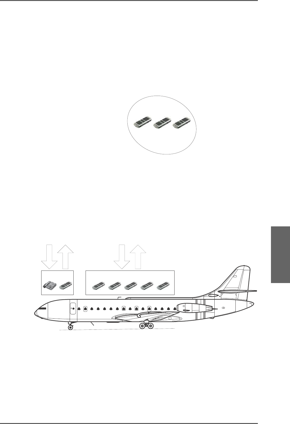
Administration of the SBU
98-124743-F Chapter 6: Configure the AVIATOR 700 system 6-91
Unassigned handsets
These are IP handsets that are not assigned a number, and that do not belong to a call type
group. Use this handset context if you want to create a group of IP handsets that can be
called together. All unassigned IP handsets will ring when you call a mobile number which
has not been assigned to a handset.
To make an IP handset unassigned, clear all call types and the Assigned number field when
setting up the handsets in the web interface. See Set the call types for AVIATOR Wireless
Handsets on page 6-46.
Figure 6-75: Multi-voice, example of unassigned handsets
Cockpit reserve
With Cockpit reserve enabled, is it possible to reserve at least one call line to the handsets in
the cockpit. The free call line is reserved for all handsets not assigned an additional Multi-
voice number.
In the following example of a Multi-voice configuration with cockpit reserve, all handsets in
the cabin have been assigned an additional number while the handsets in the cockpit
belong to the standard call type group.
Figure 6-76: Multi-voice, example for a configuration with Cockpit reserve.
&DELQ
,3KDQGVHWORFDOQR
1RQXPEHUDVVLJQHG
All handsets ring
when calling a mobile
number which is in
the subscription but
not assigned to any
handset.
&RFNSLW
&DOOW\SHJURXS
&DELQ
$GGLWLRQDOQXPEHUDVVLJQHGWRHDFK,3KDQGVHW
0RELOHQXPEHUV
$GGLWLRQDOQXPEHUV
$GGLWLRQDOQXPEHUV
0RELOHQXPEHUV
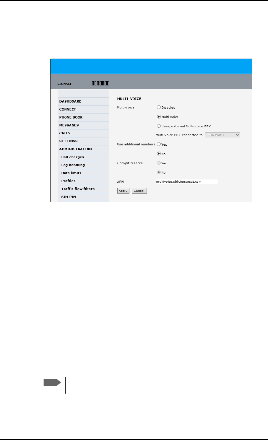
Administration of the SBU
6-92 Chapter 6: Configure the AVIATOR 700 system 98-124743-F
Configure Multi-voice
To enable and configure Multi-voice, do as follows:
1. From the left navigation pane, select Administration > Multi-voice.
Figure 6-77: Web interface: Administration, Multi-voice
2. To use the AVIATOR 700 terminal for Multi-voice, select Multi-voice.
You can also use an external Multi-voice PBX. If so, select Using external Multi-
voice PBX and select the interface used to connect the PBX to the terminal. Refer to
the manufacturer documentation for your Multi-voice PBX.
3. If you want to assign additional numbers, select Use additional numbers. You must
have additional numbers in your subscription and enter the additional numbers under
PHONE BOOK > Mobile numbers. (See also Set up additional numbers on page 6-
93.)
Then you can use the setup page for the handset interface, e.g. SETTINGS > IP
handsets > Call settings, to assign the additional numbers to the handsets you want
to be able to call directly. (See also Assign additional numbers on page 6-94).
4. You can configure a reserved line for the handsets in the cockpit by selecting Use
additional numbers and Cockpit reserve Yes.
• There will at all times be a free line for the handsets in the cockpit so a call can be
made and received regardless the use of other handsets. Set up a call type group to
assign handsets to the cockpit-reserved group, see Set the call types for AVIATOR
Wireless Handsets on page 6-46, Configure the Phone/Fax interface (2-Wire) of the
SBU on page 6-34 and Configure the ISDN interface of the SBU on page 6-35.
• Use the additional numbers for other handsets, e.g. in the cabin.
5. Type in the VoIP APN used for Multi-voice. You find the Multi-voice APN name in your
subscription documentation.
Note
The handsets using additional numbers must be AVIATOR Wireless Handsets or
other SIP phones, a normal 2-wire handset cannot be used.
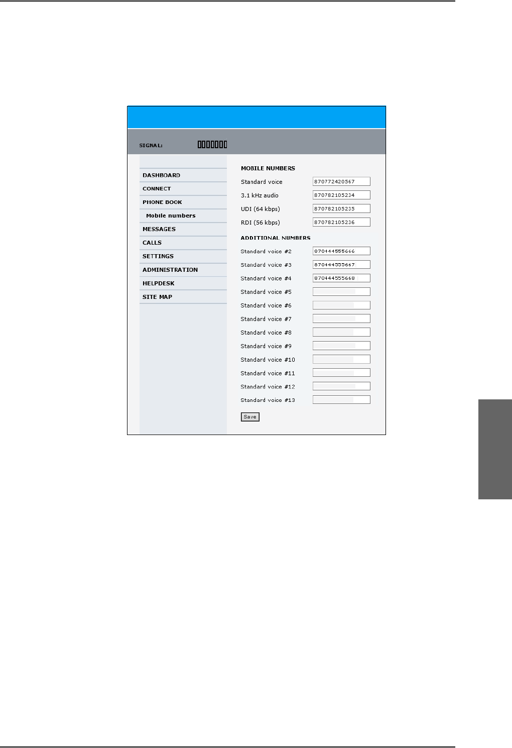
Administration of the SBU
98-124743-F Chapter 6: Configure the AVIATOR 700 system 6-93
6. Click Apply.
Set up additional numbers
Enter the additional numbers under PHONE BOOK > Mobile numbers.
Figure 6-78: Web interface: Phone book, mobile numbers (example, Multi-voice)
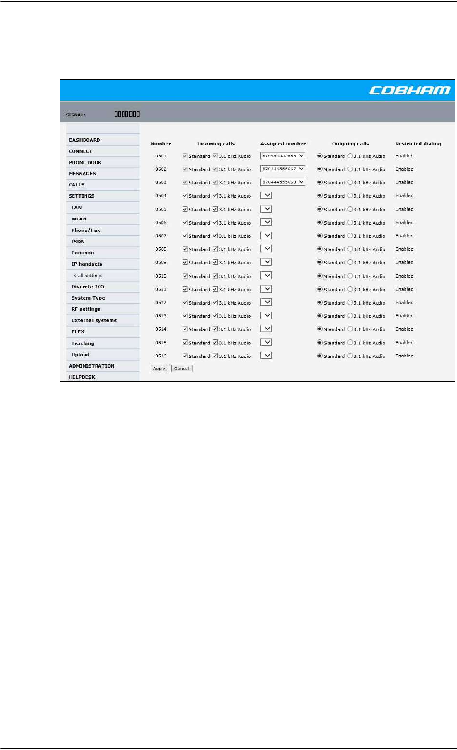
Administration of the SBU
6-94 Chapter 6: Configure the AVIATOR 700 system 98-124743-F
Assign additional numbers
Assign additional numbers under SETTINGS > IP handsets > Call settings.
Figure 6-79: Web interface: Settings, IP handsets, Call settings (with Multi-voice, example)

Site map of the SBU web interface
98-124743-F Chapter 6: Configure the AVIATOR 700 system 6-95
6.10 Site map of the SBU web interface
The web interface offers a site map page. Use this page to get an overview over the menus,
submenus and topics. The following drawing shows the site map
Figure 6-80: Web interface: Site map
.
To access the site map, select SITE MAP from the left navigation pane. You can click on
each menu in the site map to go directly to the page or display the respective submenu.
3RUWIRUZDUGLQJ
1HWZRUNGHYLFHV
1HWZRUNFODVVLILFDWLRQ
1HWZRUNXVHUJURXSV
333R(
6WDWLFURXWH
&DOOIRUZDUG
&DOOEDUULQJ
&DOOZDLWLQJ
/LQHLGHQWLILFDWLRQ
&ORVHGXVHUJURXS
/RFDOH[FKDQJH
/$1
:/$1
3KRQH)D[
,6'1
&RPPRQ
,3KDQGVHWV
'LVFUHWH,2
6\VWHPW\SH
5)VHWWLQJV
([WHUQDOV\VWHPV
)/(;
7UDFNLQJ
8SORDG
&DOOFKDUJHV
/RJKDQGOLQJ
'DWDOLPLWV
3URILOHV
7UDIILFIORZILOWHUV
6,03,1
6,0/RFN
8VHUSHUPLVVLRQV
5HPRWHPDQDJHPHQW
/LQNPRQLWRULQJ
5HPRWHDFWLYDWLRQ
5HVWULFWHGGLDOLQJ
0XOWLYRLFH
(YHQWOLVW
(YHQWORJ
([WHQGHGVWDWXV
6HOIWHVW
'$6+%2$5'
&211(&7
3+21(%22.
0(66$*(6
&$//6
6(77,1*6
$'0,1,675$7,21
+(/3'(6.
6,7(0$3
&DOOVHWWLQJV
&08$&$56

Configuration of 3rd party phone systems
6-96 Chapter 6: Configure the AVIATOR 700 system 98-124743-F
6.11 Configuration of 3rd party phone systems
6.11.1 Sigma7 setup
There are a few adjustments that are typically made at the time of installation testing.
Normally it is necessary to set the ear volume of the handset initially, in order to obtain
sufficient volume in the ear piece.
The information in this section is only meant as a guideline. For complete
information on the function of the Sigma7 handset, refer to the Sigma7 manual.
To set up the ear volume
To set up the ear volume of the handset, do as follows:
1. Take the handset out of the cradle and enter the menu system of the handset.
2. Use the volume control keys to scroll to the EARVOL setting.
3. Press the Flash key to select EARVOL.
4. Change the volume setting to 4 using the volume control keys.
5. Press # to store the setting. To adjust other settings, press Flash to return to the menu.
6. Place the handset back into the cradle.
For further information on the Sigma7 handset, refer to the manual for the Sigma7 handset.
6.11.2 ICG DECT Cordless Handset setup
It is sometimes necessary to adjust the volume of the ICG DECT Cordless Handset, in order
to have sufficient volume in the ear piece. Also, you may want to change the setting of the
handset from pulse to tone, if this is not already set.
The information in this section is only meant as a guideline. For complete
information on the function of the ICG DECT Cordless Handset phone, refer to the
manual for your ICG DECT Cordless Handset phone.
To set the volume
To change the volume setting, enter the handset menus and do as follows:
1. Scroll to Audio Sett and press OK.
2. Select H/Set Vol and press OK. The current volume is heard in the ear piece and the
level is displayed.
3. Scroll to the desired volume and press OK.
Note
When you set up Handset #5 and #6 in the Configuration Program, you must
select ICG Handset for Sigma7. See External equipment on page 6-10.
Note
Note
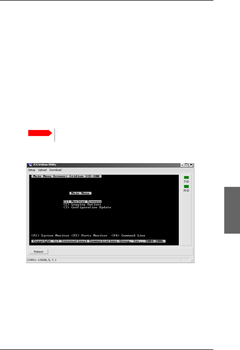
Configuration of 3rd party phone systems
98-124743-F Chapter 6: Configure the AVIATOR 700 system 6-97
To switch to Tone dialing
To change the dialing mode, do as follows:
1. Open the handset menu.
2. Scroll to Temp Tone and press OK. Tone dialing is now active.
6.11.3 Iridium Communication System, ICS-200
Overview
This section explains basic configuration of the ICS-200 system. Screen shots and
instructions are given for ICS-200 firmware revision F, minor changes or variations may
exist for newer firmware revisions.
For further information on the ICG configuration utility and the ICS-200 system in general,
please refer to the ICS-200 Installation Manual available on ICG’s homepage
http://www.intcomgrp.com.
When simultaneously operating the AVIATOR 700 over the Inmarsat network
and the ICS-200 there is a potential risk of interference.
ICS-200 is configured from the ICG configuration utility. The main menu of this application
is shown below.
Configure audio levels and outgoing routing for the 4-wire ports
1. From the Main Menu, select Configuration Update.
2. Select Configure Ports.
3. In the Ports Editor menu, select the first 4-wire port, Station 4 wire (15).
4. Change RESTRICTED_ROUTING to ENABLED, and select LBT as LBT-01.
5. Change Rx (ear) gain to -20 dBm.
Important
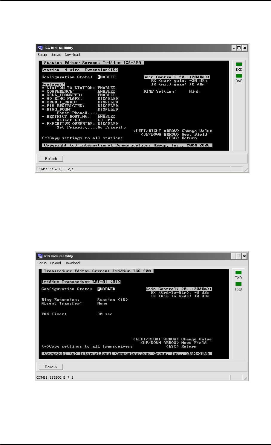
Configuration of 3rd party phone systems
6-98 Chapter 6: Configure the AVIATOR 700 system 98-124743-F
6. Verify that TX (mic) gain is set to +0 dBm and that DTMF setting is High.
Configuration of extension 15 will then be as shown below.
7. Press <Esc> to return to the Ports Editor menu.
8. Repeat the same configuration for extension 16, but set the LBT to LBT-02.
Configure incoming routing for the transceivers
1. From the Ports Editor menu, select Transceiver LBT-01 (01).
2. Configure ring extension to be Station (15).
Configuration of LBT-01 will then be as below
3. Press <Esc> to return to Ports Editor menu.
4. Repeat the same configuration for LBT-02, but set the ring extension to Station (16).
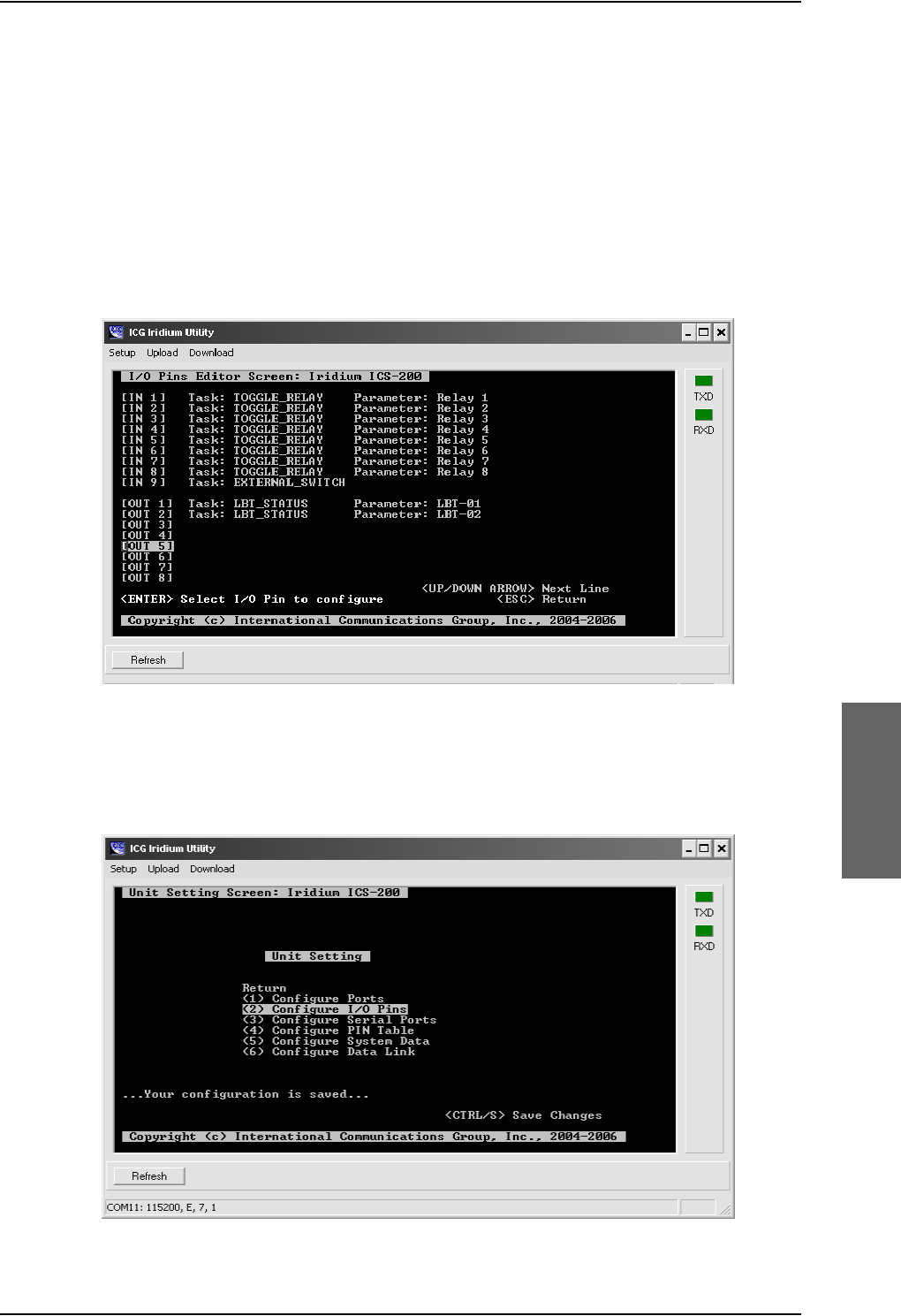
Configuration of 3rd party phone systems
98-124743-F Chapter 6: Configure the AVIATOR 700 system 6-99
Configure I/O pins
1. Press <Esc> until you are back in the Unit Setting menu.
2. Choose Configure I/O pins.
3. In the I/O Pins Editor menu, select OUT 1 and then select Task as LBT_AVAIL and
parameter as LBT-01.
4. In the I/O Pins Editor menu, select OUT 2 and then select Task as LBT_AVAIL and
parameter as LBT-02.
The I/O Pins Editor menu should then look as below.
Save settings and reboot
1. Press <Esc> to get back to the Unit Setting menu, and then use CTRL-S to save the
settings.
ICS-200 then responds Configuration is saved as below.
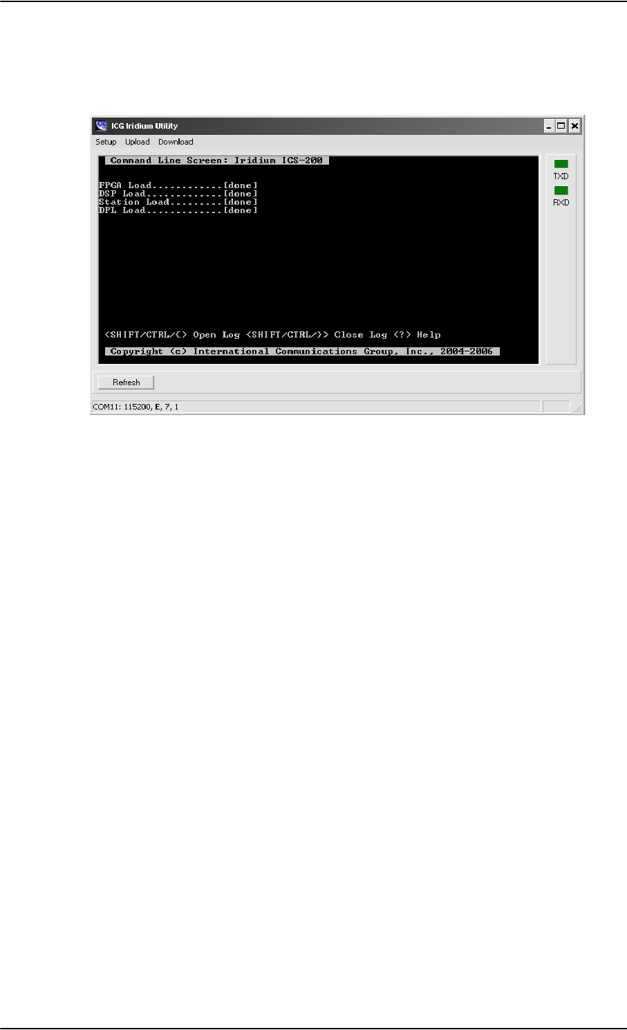
Configuration of 3rd party phone systems
6-100 Chapter 6: Configure the AVIATOR 700 system 98-124743-F
2. Press F4 to get a command prompt, then type reset and press <Enter> to reset the
unit for the new settings to take effect.
The response should be as shown below.
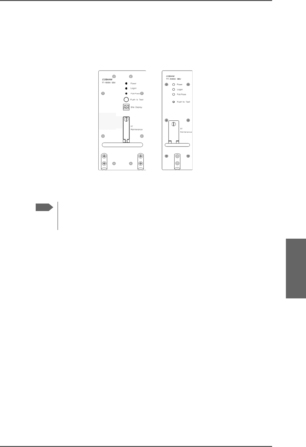
AVIATOR 700 system ready for use
98-124743-F Chapter 6: Configure the AVIATOR 700 system 6-101
6.12 AVIATOR 700 system ready for use
Having installed the AVIATOR 700 system, activated the SIM card, entered the ICAO
number and configured the system you can verify whether the system is fully operational.
Check that all LEDs on the SDU and SBU front panel are green.
Figure 6-81: AVIATOR 700 system ready for use
Note
Line of sight during operation!
Make sure that there is a line of sight between the Satcom antenna and the
satellite in order to logon to and use the satellite service.
*UHHQ/('VRQ6'8
DQG6%8
3RZHU
/RJRQ
)DLO3DVV
6%8
6'8

AVIATOR 700 system ready for use
6-102 Chapter 6: Configure the AVIATOR 700 system 98-124743-F

98-124743-F 7-1
Chapter 7
Check procedures 7
7.1 Basic check flow
7.1.1 Check procedures
In order to ensure the correct function of the system, the below check flow should be
followed.
1. Pre-Installation Check.
Perform this check after wiring, but before inserting the LRUs.
This is a check of the most important connections, the circuit breakers, cable losses etc.
Refer to Pre-Installation Check on page 7-2.
2. Configuration.
After performing the Pre-Installation Check, configure the system using the Aero-SDU
Configuration Program and the SBU web interface.
Refer to Configure the AVIATOR 700 system on page 6-1.
3. Functional Test, on Ground.
When the system is configured and activated, a functional test should be performed.
The functional test should check all user interfaces, such as voice, fax, high speed data,
annunciators, satcom on/off switch etc.
Refer to Functional Test, on Ground on page 7-4.
4. Interference Test.
After the functional test, an interference test should be performed. This test is to verify
that transmission from the AVIATOR 700 system has no effect on the avionics of the
aircraft, particularly navigation equipment.
Refer to Interference Test on page 7-6.
5. Functional Test, Airborne.
After the interference test, a functional test should be performed while the aircraft is
airborne. This test is basically the same as the functional test on ground. Refer to
Functional Test, Airborne on page 7-7.
Important
None of the check procedures described in this chapter can serve as a
replacement for any of the required approvals and certifications.
Note
If additional avionics are installed in the aircraft at a later stage, the
interference test should be performed again to ensure correct operation.

Pre-Installation Check
7-2 Chapter 7: Check procedures 98-124743-F
7.2 Pre-Installation Check
It is recommended to check the installation before inserting LRUs. The following list
provides some of the most important issues, but other additional checks may be relevant
for the specific installation.
Item Description of Check Reference
Section Value/
Comment
Mounting
trays
Ensure service/maintenance accessibility. 5.2
Coding of
tray
connectors
Check orientation of coding pins in SDU
tray connector
4.1.3
Check orientation of coding pins in HPA
tray connector
4.2
Check orientation of coding pins in SBU
tray connector
4.3.3
Quadrax
insert
orientation
Check that the Quadrax connector is
oriented correctly in the SDU tray
connector.
4.1.3
Check that the Quadrax connectors are
oriented correctly in the SBU tray
connector.
4.3.3
Grounding
stud
Check that the grounding stud on the
DLNA is connected correctly to aircraft
chassis.
Circuit
breaker
rating
Check the SDU circuit breaker: 4 A 5.3.3
Check the HPA circuit breaker: 20 A 5.3.3
Check the SBU circuit breaker: 7.5 A 5.3.3
Polarity of
28 V DC
Power
Check 28 V DC polarity on SDU tray
connector
(TP1: +28 V DC Power and TP2: GND,
Power Return)
4.1.3
5.3.3
Check 28 V DC polarity on HPA tray
connector
(BPA1: +28 V DC Power and BPA2: GND,
Power Return)
4.2
5.3.3
Table 7-1: Check Sheet: Installation Check Before Inserting LRUs.

Pre-Installation Check
98-124743-F Chapter 7: Check procedures 7-3
After a successful check of the installation, use the Aero-SDU Configuration Program and
the built-in web interface of the SBU to configure the system. For further information, refer
to Configure the AVIATOR 700 system on page 6-1.
Check 28 V DC polarity on SBU tray
connector
(TP1: +28 V DC Power and TP2: GND,
Power Return)
4.3.3
5.3.3
Handset
power
Check power to the handsets on DB15
connector to be inserted in cradle
5.3.11
4.4.2
SDU nON Check that TP5 (nOn) on the SDU tray
connector is connected to a switch or
directly to Chassis GND (TP3).
5.3.3
4.1.3
SBU nON Check that TP3 (nOn) on the SBU tray
connector is connected to a switch or
directly to Chassis GND (BP3).
5.3.3
4.3.3
Handset
connections
to Cradles
Check that 2-wire handsets are not
connected to 4-wire cradles.
5.3.11
RF cable
losses
Measure and note the cable loss from
SDU to DLNA
5.3.4
6.2.3
Measure and note the cable loss from
SDU to HPA
Measure and note the cable loss from
HPA to DLNA
Measure and note the cable loss from
DLNA to Antenna
Measure and note the cable loss from
SBU to Rx Power Splitter
Measure and note the cable loss from
SBU to Tx Coupler
Software
version
Check the software version of the SDU.
Check the software version of the SBU.
Note
The cable loss values registered in the above table must be entered into the Aero-
SDU Configuration Program during configuration.
Item Description of Check Reference
Section Value/
Comment
Table 7-1: Check Sheet: Installation Check Before Inserting LRUs. (Continued)

Functional Test, on Ground
7-4 Chapter 7: Check procedures 98-124743-F
7.3 Functional Test, on Ground
7.3.1 Before you start
The system must be activated before performing this test. For further details see Activation
of airtime services on page 5-86.
7.3.2 Check list for functional test on ground
The following list provides some of the most important checks to perform after power-up,
but other additional checks may be relevant for the specific installation.
If you already know that certain interfaces or services are not going to be used, it is not
necessary to perform tests on these specific interfaces or services.
Item Description of Check Reference Value/
Comment
SDU LEDs Check that the SDU Power LED is
green
Check that the SDU Fail/Pass LED is
green
Check that the SDU Logon LED is
green
SBU LEDs Check that the SBU Logon LED is
green
Voice
handsets #1 to
#6
Make an aircraft to ground call AVIATOR 700
User Manual
Make a ground to aircraft call AVIATOR 700
User Manual
SDU - Fax Send an H+ fax from aircraft to
ground
AVIATOR 700
User Manual
Send an H+ fax from ground to
aircraft
AVIATOR 700
User Manual
Send an HSD fax from aircraft to
groundaAVIATOR 700
User Manual
Send an HSD fax from ground to
aircraftaAVIATOR 700
User Manual
SBU - Fax Send a fax over SwiftBroadband
from ground to aircraft.
AVIATOR 700
User Manual
Send a fax over SwiftBroadband
from aircraft to ground.
AVIATOR 700
User Manual
Table 7-2: Check Sheet: Functional Test, on Ground

Functional Test, on Ground
98-124743-F Chapter 7: Check procedures 7-5
SBU - ISDN Connect to the internet from a
laptop, using the ISDN connection.
AVIATOR 700
User Manual
SBU - Ethernet Connect to the internet from a
laptop, using the Ethernet
connection.
AVIATOR 700
User Manual
SBU- WLAN Connect to the internet from a
laptop, using the WLAN connection.
AVIATOR 700
User Manual
ACARS / AFIS /
CMU
Send test message and verify reply
or request for weather data and
verify the data is downloaded. Both
is done from the CDU / MCDU.
CDU / MCDU
Manual
a. HSD fax available on I3 satellites.
Item Description of Check Reference Value/
Comment
Table 7-2: Check Sheet: Functional Test, on Ground (Continued)

Interference Test
7-6 Chapter 7: Check procedures 98-124743-F
7.4 Interference Test
7.4.1 Introduction
It is recommended to perform an interference test to ensure that transmission from the
AVIATOR 700 system does not influence any of the primary avionics on the aircraft.
7.4.2 Test
During the test, the aircraft must be on ground. A skilled person should be observing the
instruments.
1. Log on to the satellite in the lowest possible elevation.
2. Place the aircraft in such a position that the satcom antenna transmits in the direction
of the other antennas on the aircraft.
Example: If the satcom antenna is tail-mounted, place the aircraft with the nose
pointing in the direction of the satellite. The antenna will then transmit in
the direction of the other antennas placed in front of it.
3. While transmission is ongoing, observe all primary navigation instruments, autopilot,
VOR/ILS, ADF and DME etc. and make sure none of the instruments are influenced by
the AVIATOR 700 transmission.
4. Check GPS signal-to-noise ratio.
5. Monitor all VHF communication and make sure squelch is not opened unintentionally.
6. To check that the SBU can send continuously at a high data rate over SwiftBroadband
make a 3.1 kHz audio call from the SBU.
7. If TCAS/ACAS is installed, verify that it is not flagged “FAILED” during satcom
transmission.
Important
This test is not a replacement for any EMC tests in connection with e.g. an
STC, TC or Field Approval. It is only an additional practical test of the
application.
Note
If any additional avionics are installed at a later stage, the interference test should
be performed again.

Functional Test, Airborne
98-124743-F Chapter 7: Check procedures 7-7
7.5 Functional Test, Airborne
The following list provides some of the most important checks to perform while the aircraft
is airborne, after all on-ground tests are passed. Other additional checks may be relevant for
the specific installation. If you already know that certain interfaces or services are not going
to be used, it is not necessary to perform tests on these specific interfaces or services.
If any of the checks should fail, guidance is provided in the section Initial troubleshooting
on page 8-26.
Item Description of Check Reference Value/
Comment
SDU - Voice Make an air to ground call and keep it
up during a 360 turn. Monitor the
C/No for any drops during the turn.
AVIATOR 700
User Manual
Make a ground to air call AVIATOR 700
User Manual
SBU - Voice Make an air to ground call and keep it
up during a 360 turn. Monitor the
C/No for any drops during the turn.
AVIATOR 700
User Manual
Make a ground to air call AVIATOR 700
User Manual
SDU - Fax Send an H+ fax from air to ground AVIATOR 700
User Manual
Send an H+ fax from ground to air AVIATOR 700
User Manual
Send an HSD fax from air to ground AVIATOR 700
User Manual
Send an HSD fax from ground to air AVIATOR 700
User Manual
SBU - Fax Send a fax over SwiftBroadband from
ground to aircraft.
AVIATOR 700
User Manual
Send a fax over SwiftBroadband from
aircraft to ground.
AVIATOR 700
User Manual
SBU - ISDN Connect to the internet from a laptop,
using the ISDN connection.
AVIATOR 700
User Manual
SBU -
Ethernet
Connect to the internet from a laptop,
using the Ethernet connection.
AVIATOR 700
User Manual
SBU- WLAN Connect to the internet from a laptop,
using the WLAN connection.
AVIATOR 700
User Manual
Table 7-3: Check Sheet: Functional Test, Airborne

Functional Test, Airborne
7-8 Chapter 7: Check procedures 98-124743-F
ACARS /
AFIS / CMU
Send test message and verify reply or
request for weather data and verify
the data is downloaded. Both is done
from the CDU / MCDU.
CDU / MCDU
Manual
Item Description of Check Reference Value/
Comment
Table 7-3: Check Sheet: Functional Test, Airborne (Continued)

98-124743-F 8-1
Chapter 8
Maintenance and troubleshooting 8
8.1 Continued Airworthiness
8.1.1 General
Maintenance
Maintenance requirements and instructions for continued airworthiness of the Cobham
SATCOM units in the AVIATOR 700 System are restricted to the fact that the TT-5035A
Satellite Data Unit requires replacement of an internal battery at a periodic scheduled
service task of 7 years (Overhaul). The Overhaul period is defined as the recommended
period from production date or last maintenance to next maintenance.
When replacing the TT-5035A Satellite Data Unit (SDU), it is important to
leave the TT-5035A-001 Configuration Module (CM) behind, attached to the
airframe with a wire.
When replacing the TT-5040A SwiftBroadband Unit (SBU), it is important to
leave the TT-5040A-001 Configuration Module behind, attached to the airframe
with a wire.
Contact for support
AVIATOR 700 system purchased from a Cobham SATCOM distributor: If you need
assistance and you have purchased your system from a Cobham SATCOM distributor,
contact the distributor’s support line.
AVIATOR 700 system purchased directly from Cobham SATCOM: If you need
assistance and you have purchased your system directly from Cobham SATCOM, you can
contact Cobham SATCOM by telephone or send an e-mail to the Cobham SATCOM
esupport.
Telephone numbers:
For urgent technical support please contact us at one of the following numbers:
•One Dial Phone: +45 39 88 89 89
• US, Virginia Beach office: +1 757 463 9557 or +1 866 SATCOMS.
The eSupport e-mail address is AVIATOR.support@cobham.com.
Note
Note

Continued Airworthiness
8-2 Chapter 8: Maintenance and troubleshooting 98-124743-F
8.1.2 Instructions
Documentation
Maintenance information for the AVIATOR 700 System is contained in this manual. Place
the wiring diagram information in this manual in the aircraft operator's appropriate aircraft
wiring diagram manuals.
Inoperative units
If a system component is inoperative, remove or replace the unit.
If a level-D certified system detects an inconsistent hardware unit (level E) or
software image (level E), it enters failure mode and the system will not be
operational. Inconsistency messages are displayed to clearly inform the
service personnel about the reason for this failure mode.
If an inoperative SDU is removed, take out the TT-5035A-001 Configuration Module (CM)
and fasten the CM and wiring. Secure all cables, collect applicable switches and circuit
breakers, and label them inoperative. Revise the equipment list and weight and balance as
applicable prior to flight and make a log book entry that the unit was removed.
Likewise, if an inoperative SBU is removed, take out the TT-5040A-001 CM and fasten the
CM and wiring to the air frame. Secure all cables, collect applicable switches and circuit
breakers, and label them inoperative. Revise the equipment list and weight and balance as
applicable prior to flight and make a log book entry that the unit was removed.
For information on how to return a unit for repair, see Returning units for repair on page 8-
30. Once repaired, reinstall the unit in the aircraft in accordance with the instructions in this
Installation and Maintenance Manual.
Scheduled Maintenance Program
The high-speed data system components are considered on-condition units and no
additional maintenance is required other than a check for security and operation at normal
inspection intervals.
Scheduled Maintenance Program tasks to be added to the aircraft operator's appropriate
aircraft maintenance program are as follows:
Important

Continued Airworthiness
98-124743-F Chapter 8: Maintenance and troubleshooting 8-3
Recommended Periodic Scheduled Servicing Tasks:
TT-5035A Satellite Data Unit (SDU) 7 years
TT-5040A SwiftBroadband Unit (SBU) None required
TT-5035A-001 Configuration Module (CM) None required
TT-5040A-001 Configuration module for SBU None required
TT-5014A High Power Amplifier (HPA) None required
TT-5620A 4-Wire Handset None required
TT-5622A 4-Wire Cradle None required
TT-5621B 2-Wire Handset None required
TT-5622B 2-Wire Cradle None required
TT-5013A Type-F DLNA
(Original Manufacturer P/N: COMDEV 173628-
101)
None required
TT-5624B AVIATOR Wireless Handset
TT-5626B Cradle for AVIATOR Wireless Handset
See AVIATOR Wireless Handset and
Cradle Installation & Maintenance
Manual (98-129600).
Recommended Periodic Inspections:
TT-5035A Satellite Data Unit (SDU) None required
TT-5040A SwiftBroadband Unit (SBU) None required
TT-5035A-001 Configuration Module (CM) None required
TT-5040A-001 Configuration module for SBU None required
TT-5014A High Power Amplifier (HPA) None required
TT-5620A 4-Wire Handset None required
TT-5622A 4-Wire Cradle None required
TT-5621B 2-Wire Handset None required
TT-5622B 2-Wire Cradle None required
TT-5013A Type-F DLNA
(Original Manufacturer P/N: COMDEV 173628-
101)
None required
TT-5624B AVIATOR Wireless Handset
TT-5626B Cradle for AVIATOR Wireless Handset
See AVIATOR Wireless Handset and
Cradle Installation & Maintenance
Manual (98-129600).

Continued Airworthiness
8-4 Chapter 8: Maintenance and troubleshooting 98-124743-F
Recommended Periodic Scheduled Preventative Maintenance Tests:
(Tests to determine system condition and/or latent failures)
TT-5035A Satellite Data Unit (SDU) None required
TT-5040A SwiftBroadband Unit (SBU) None required
TT-5035A-001 Configuration Module (CM) None required
TT-5040A-001 Configuration module for SBU None required
TT-5014A High Power Amplifier (HPA) None required
TT-5620A 4-Wire Handset None required
TT-5622A 4-Wire Cradle None required
TT-5621B 2-Wire Handset None required
TT-5622B 2-Wire Cradle None required
TT-5013A Type-F DLNA
(Original Manufacturer P/N: COMDEV 173628-
101)
None required
TT-5624B AVIATOR Wireless Handset
TT-5626B Cradle for AVIATOR Wireless Handset
See AVIATOR Wireless Handset and
Cradle Installation & Maintenance
Manual (98-129600).
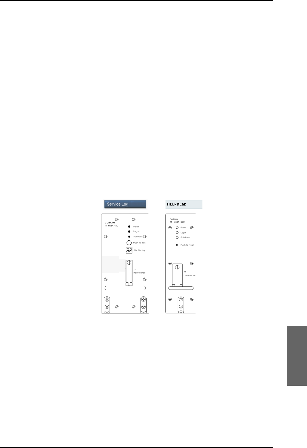
Getting support: Service log and HELPDESK
98-124743-F Chapter 8: Maintenance and troubleshooting 8-5
8.2 Getting support: Service log and HELPDESK
If this manual does not provide the remedies to solve your problem, you may want to
contact your Airtime Provider or your local distributor.
8.2.1 Airtime support
If you need assistance from your Airtime Provider, call the help desk, click HELP DESK or
check your Airtime subscription for a contact number.
8.2.2 System support
If you need assistance with problems caused by the SDU, SBU, and HPA or the antenna,
please call a distributor in your area. A list of certified partners and distributors is available
on Cobham SATCOM web site: www.cobham.com/satcom. Select Where to buy, then
AVIATOR, EXPLORER, SAILOR and Sea Tel branded products resellers.
There are two tools available to help you troubleshooting the system.
Figure 8-1: Support tools: Service log and Helpdesk
8.2.3 Service Log for the SDU
Generating a service log
When contacting your distributor for support, please include a service log. The service log
contains information relevant for the service personnel during troubleshooting. When
contacting your distributor for support, please enclose the service log for the SDU and the
diagnostic report for the SBU.
6%8
ZHELQWHUIDFH
$HUR6'8
&RQILJXUDWLRQ
3URJUDP
6%8
6'8
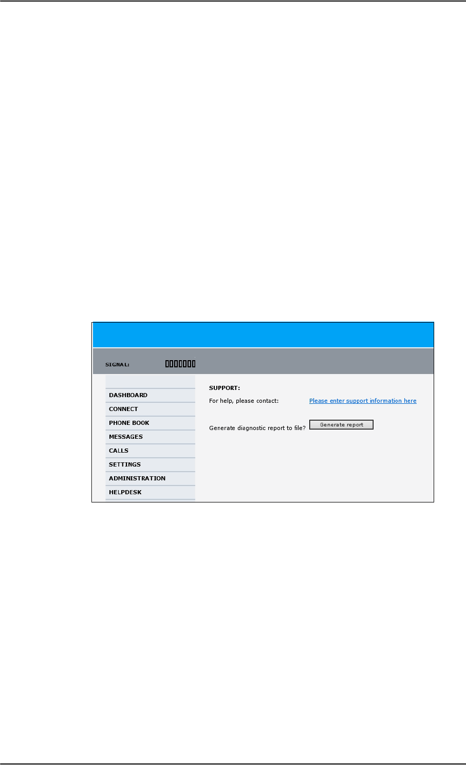
Getting support: Service log and HELPDESK
8-6 Chapter 8: Maintenance and troubleshooting 98-124743-F
To generate a service log, do as follows:
1. In the Aero-SDU Configuration Program click the button Service Log on the start
page.
2. Choose a location for the file and click OK to save it.
3. It may take several minutes to complete the service log, wait until the operation is
completed.
The service log contains also BITE error codes from the SDU, including 2 general BITE
codes from the SBU. These SBU BITE codes inform you that there are errors in the SBU. Use
the SBU diagnostic report for further information on the SBU BITE errors.
8.2.4 Help desk and diagnostic report from the SBU
Help desk
If you need help with airtime-related issues for the SwiftBroadband subscription you
may call the Help desk. Enter the phone number for your Airtime Provider on this page. To
access the Help desk, select HELP DESK from the left navigation pane in the SBU web
interface.
Figure 8-2: Web interface: Help desk
If you have entered the Help desk number, it is displayed as a link. To change the number,
click the link, change the number and click Apply. If you need help with SBU- or
antenna-related issues call your local distributor.
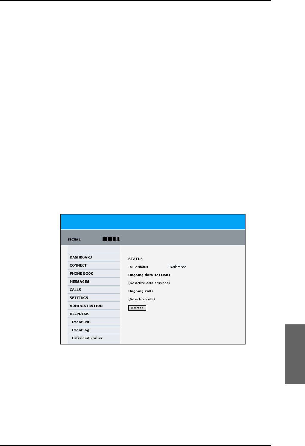
Getting support: Service log and HELPDESK
98-124743-F Chapter 8: Maintenance and troubleshooting 8-7
Generating a diagnostic report from the SBU
When contacting your distributor for support, please include an SBU diagnostic report. The
diagnostic report contains information relevant for the service personnel during
troubleshooting. When contacting your distributor for support, please enclose the service
log for the SDU and the diagnostic report for the SBU.
To generate a diagnostic report with valuable information for the service team, do as
follows:
1. Reboot the system.
2. Establish the problem or situation in which the error occurred, or
3. Make a CS call (if possible), i.e. making a call with a handset connected to the SBU.
4. Make a PS call (if possible), i.e. establish a data connection.
5. Click Generate report from the HELP DESK page.
In some browsers the file may open directly in your browser. If it does, choose File >
Save As to save the file.
6. Choose a location for the file and save it on your computer.
Extended status
Click Extended status in the HELP DESK page to display further status information on
logon status, ongoing data sessions and ongoing calls.
Figure 8-3: Web interface: Help desk, Extended status
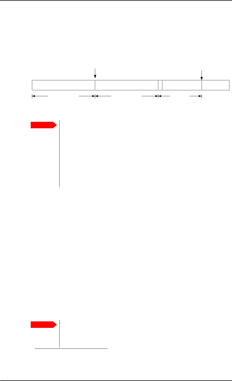
Software update
8-8 Chapter 8: Maintenance and troubleshooting 98-124743-F
8.3 Software update
The software upgrade procedure can be divided into 3 steps: SDU software upload,
AVIATOR 700 startup and SBU software upload. In step 2 the HPA is updated and the
system runs a POST (power on self test).
Figure 8-4: Software upgrade procedure for SDU and SBU
Minimum Software Version required for AVIATOR 700 (Level E):
• SBU: AVIATOR 700: Swift_broadband-E_105.zip
File: Swift_broadband-E_105.dl1
• SDU: AVIATOR 700: Aero-HSD+_E_v114.zip
File: HplusHsdHpa-E-318.swu
• Aero-SDU Configuration Program: Aero-SDU_CP_v114.zip
File: setup.exe
Minimum Software Version required for AVIATOR 700D (Level D):
• SBU: AVIATOR 700D: Swift_broadband-D_200.zip
File: Swift_broadband-D_200.dl
• SDU: AVIATOR 700D: Aero-HSD+_D_v200.zip
File: HplusHsdHpa-D-318.swu
• Aero-SDU Configuration Program: Aero-SDU_CP_v114.zip
File: setup.exe
Important
Level-D and Level E consistency!
A level-D certified system detecting an inconsistent hardware unit or
software image enters failure mode, and the system will not be operational.
Inconsistency messages clearly inform the service personnel about the
reason for this failure mode.
Pay great attention to selecting the correct software file: Level D or Level E for
both SDU and SBU. A mismatch of Level D and Level E software is not
allowed and will result in a non-functioning system. A mismatch will
be displayed in the built-in web interface and as a BITE error.
6'8VRIWZDUHXSORDG
XVLQJWKH$HUR6'8&RQILJXUDWLRQ3URJUDP
$9,$725V\VWHPVWDUWXS
XVLQJWKH$HUR6'8&RQILJXUDWLRQ3URJUDP
6%8VRIWZDUHXSORDG
XVLQJWKHZHELQWHUIDFH
$SSUR[LPDWHO\PLQXWHV $SSUR[LPDWHO\PLQXWHV VHYHUDOPLQXWHV
$OOXQLWV
UHERRW 6%8
UHERRWV
6\VWHP
UHDG\IRUXVH
1. For Level E, this software version is not mandatory, but recommended.
Important
When making a software update of the AVIATOR 700 system, you must
always update the SBU and the SDU software because the two software
versions must match as specified above. Both update procedures are
described in this chapter.

Software update
98-124743-F Chapter 8: Maintenance and troubleshooting 8-9
A POST error (UU24) is displayed if there is a mismatch between the software versions or if
the RS422 connection between the SDU and SBU is not working properly.
Hardware and software requirements
The following items are required before the software can be updated:
• One IBM compatible PC with a 9-pin serial COM port (if not available, a USB to serial
port converter can be used) and a standard Ethernet port available.
• Minimum PC requirements: Processor speed: 1 GHz, 512 MB RAM.
Operating system for SDU configuration: Windows 7, 8 or 10.
Browsers for SBU configuration: Minimum Internet Explorer 7, Mozilla Firefox 2.0 or
Apple Safari 2.0.
• One serial maintenance cable 9-pin to 15-pin Sub-D, Cobham SATCOM part no. 37-
112940. Refer to Figure 5-35: TT 37-112940 maintenance cable for front
connector on SDU and PC.
•One straight LAN cable.
•The Cobham SATCOM Aero-SDU Configuration Program (Cobham SATCOM part no.
84-119958-114 or greater) installed on the PC. This program can be downloaded from
https://sync.cobham.com/satcom/support/downloads or
http://www.cobham.com/cobham-satcom-service-and-support for non-partners.
Select Product software > Aeronautical > Satcom Systems to narrow the search.
• An unzip program installed on the PC (e.g. WinZip)
• The zipped files containing the new software: 1 file for the SDU and 1 file for the SBU.
The new software can be downloaded from
https://sync.cobham.com/satcom/support/downloads or
http://www.cobham.com/cobham-satcom-service-and-support for non-partners.
Select Product software > Aeronautical > Satcom Systems to narrow the search.

Software update
8-10 Chapter 8: Maintenance and troubleshooting 98-124743-F
8.3.1 SDU
Preparing the software update
1. On the PC, unzip the zip file containing the new software for the SDU. Remember or
write down which folder you extracted the file to.
2. Connect the SDU front port to the PC COM port, using the interconnect cable.
3. Power on the AVIATOR 700 system.
4. Close all other applications on the PC.
5. Start the Aero-SDU Configuration Program.
6. Normally you will enter the program in the Start Up tab window. If not, then select
Window, Start up from the top menu bar.
7. From the top menu bar select View, Options. Select the COM port that you connected
to the SDU in step 2.
8. Click the button SW Update. A new tab window, Software Update, opens.
9. Click on the '…' button next to the File Selection box in order to find the software file
to upload. Find the file extracted in step 1 and open it.
Updating the software
1. Click the Start button in the field SW Update.
2. The software upload to the SDU is now in progress. You can follow the status in the
progress bar. The upload will take about 8 minutes.
3. Should you experience a time-out failure during the upload, just wait 2 minutes and
click Start again. The upload will then start over again.
4. When the upload has finished, wait 8 minutes while the SDU initializes and runs a self
test. The Aero-SDU Configuration Program will guide you.
5. Do not start the upload of new software to the SBU before the SDU software update
has finished successfully.
If software upload fails - how to recover
In rare cases the software upload may fail, leaving the software in the SDU corrupted. This
will happen if the power to the SDU is interrupted during the first stage of the upload. If all
3 LEDs on the front stay orange after power up, the software is corrupted.
To recover from this, reload the software with the Aero-SDU Configuration Program as
follows:
1. Turn off the SDU.
2. Open the Aero-SDU Configuration Program and click the Software update button.
3. Click the Start button and turn on the SDU immediately after.
Note
Software update should only be done by qualified service personnel.

Software update
98-124743-F Chapter 8: Maintenance and troubleshooting 8-11
4. Continue as shown in Updating the software on page 8-10.
8.3.2 SBU
Preparing the software update
1. On the PC, unzip the zip file containing the new software for the SBU. Remember or
write down which folder you extracted the file to.
2. Connect the SBU to the PC LAN port, using the SBU maintenance connector and a
straight LAN cable.
3. Power on the AVIATOR 700 system.
4. Open your browser and enter the IP address of the SBU. The standard IP address is
192.168.0.1.
If the local IP address of the SBU has been changed and you do not have the
new address, you can temporarily set the IP address to the default value by
pushing the Reset button next on the front plate of the SBU. For detailed
instructions see How to reset the IP address or the terminal software to
default settings on page 8-23.
For further information on the Reset button, see IP Reset (Default) button on
the SBU on page 8-22.
For further information on IP addresses of the SBU see Set up the LAN IP
addressing on page 6-28.
5. Wait until step 2 in the SDU upgrade procedure has finished.
6. In the start-up page of the Aero-SDU Configuration Program click the SBU Dashboard
button to access the SBU web interface.
Note
Software update should only be done by qualified service personnel.
Note
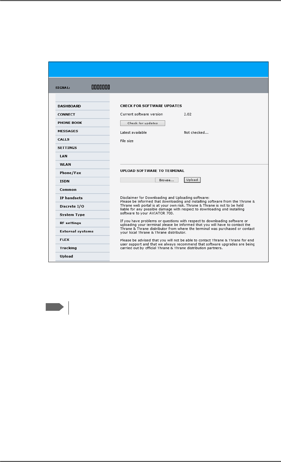
Software update
8-12 Chapter 8: Maintenance and troubleshooting 98-124743-F
Updating the software
1. In the web interface of the SBU, select SETTINGS from the left navigation pane.
2. Click Upload from the left navigation pane.
Figure 8-5: Web interface: Settings, Upload
3. The Current software version field shows the current software version.
4. To automatically find new software available click Check for updates.
This works from software 1.06 (Level D) and 2.01 (Level E).
or click Browse...
5. Browse to the new software version and accept it.
6. Click the Upload button.
Note that the upload procedure takes a couple of minutes. Follow the instructions given
in the Aero-SDU Configuration Program. When done, the SBU automatically restarts
with the new software version.
If software upload fails - how to recover
To recover from a failed software upload, turn off the SBU and turn it on again. Then repeat
the upload procedure as described in Updating the software on page 8-12.
If software upload still fails, use the IP Reset button as described in IP Reset (Default)
button on the SBU on page 8-22 to initiate a software upload from an external server.
Note

Software update
98-124743-F Chapter 8: Maintenance and troubleshooting 8-13
8.3.3 Verifying the software update
Testing procedure
1. Verify in the Aero-SDU Configuration Program (Button Software update, link: Show
more info) that a green bar appears for the SDU in the SW status field, and that the
version number in the same line is the new version number. The SBU software version
can be viewed in the DASHBOARD window of the web interface.
2. After completing the software update procedure, the SDU and the SBU will perform a
POST (Power On Self Test).
3. When the POST has finished, the green Fail/Pass LED on the front of the SDU and/or the
SBU must become steadily green. Verify that the Fail/Pass LED is not red nor flashing
orange once every 2 seconds. Wait until the Fail/Pass LED is green.
4. Verify that the software update has been completed successfully. You find the software
version number in the DASHBOARD window of the web interface.
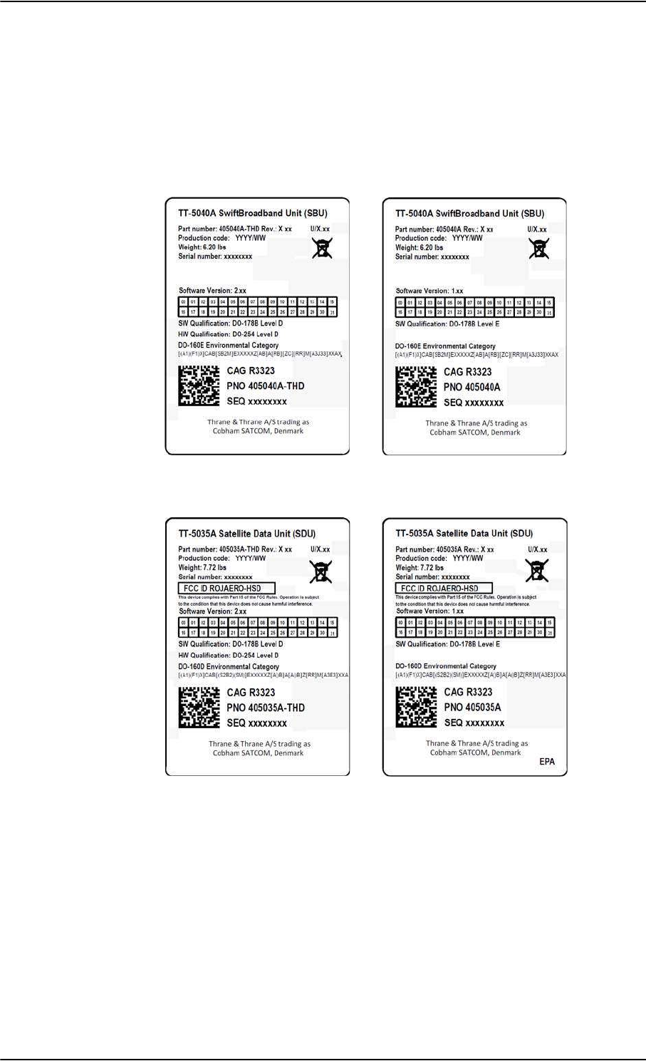
Software update
8-14 Chapter 8: Maintenance and troubleshooting 98-124743-F
Software identification procedure
On the PartNumber / SerialNumber identification label make a cross mark in the Software
Ver. field number according to the new software version. This applies to the SDU 405035A
or 405035A-THD and the SBU 405040A or 405040A-THD in the AVIATOR 700
configuration.
Figure 8-6: Software identification on the SBU label, Level D and Level E
Figure 8-7: Software identification on the SDU label, Level D and Level E
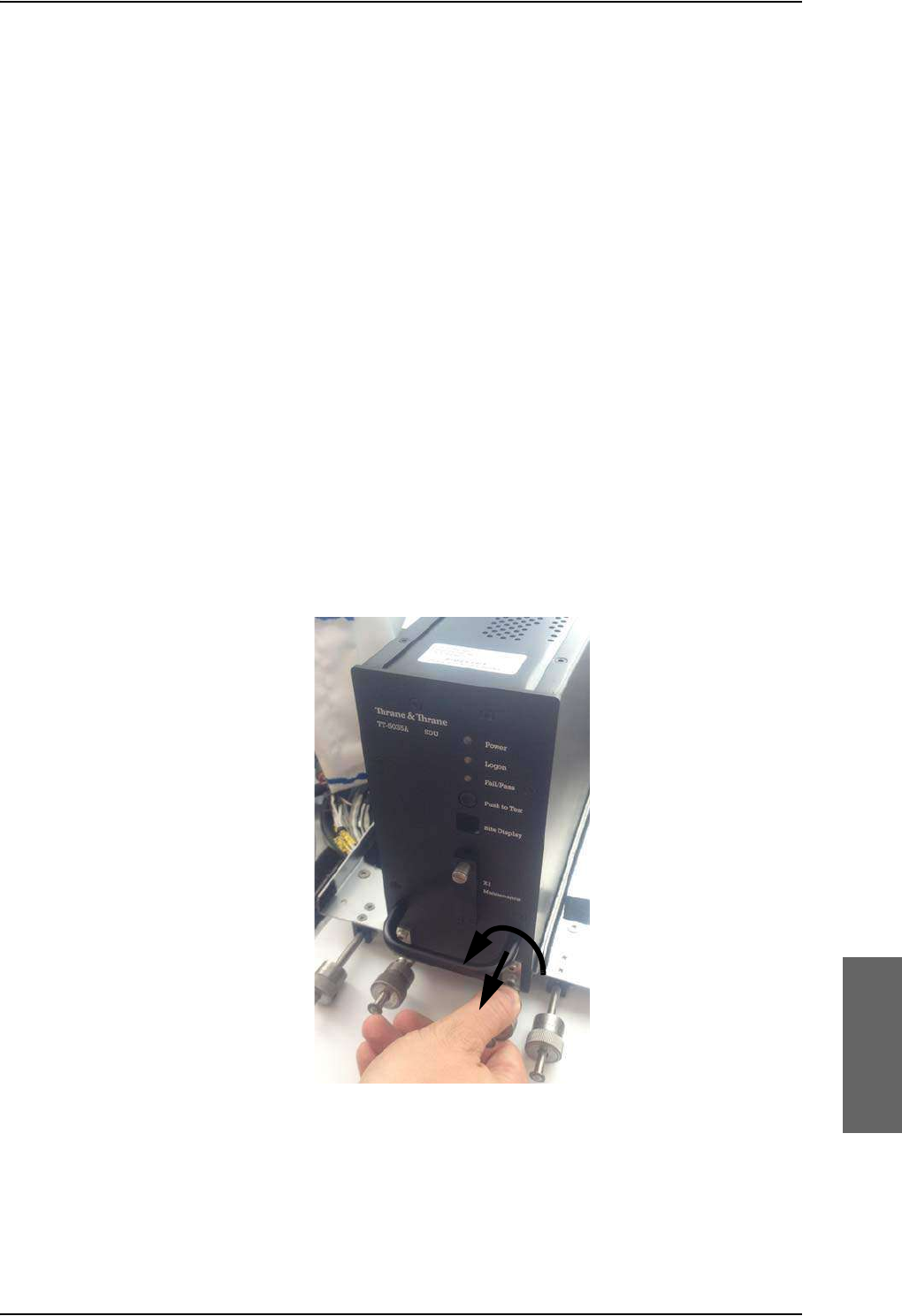
Exchanging LRUs
98-124743-F Chapter 8: Maintenance and troubleshooting 8-15
8.4 Exchanging LRUs
This document describes the procedures for removal and re-installation of an AVIATOR 700
LRU:
• SDU (405035A-THD)
• HPA (405014A-THD)
• SBU (405040A-THD).
8.4.1 Time consumption
The time consumption for removal and re-installation of an LRU is estimated to 15 minutes.
8.4.2 Tools
No tools required.
8.4.3 Removal and re-installation of the SDU or the SBU
1. Ensure that power is removed from the satcom system before removing any LRU!
2. Pull and turn to loosen the knurled knob(s) that retain(s) the LRU in the tray.
Figure 8-8: Exchanging an LRU (example)
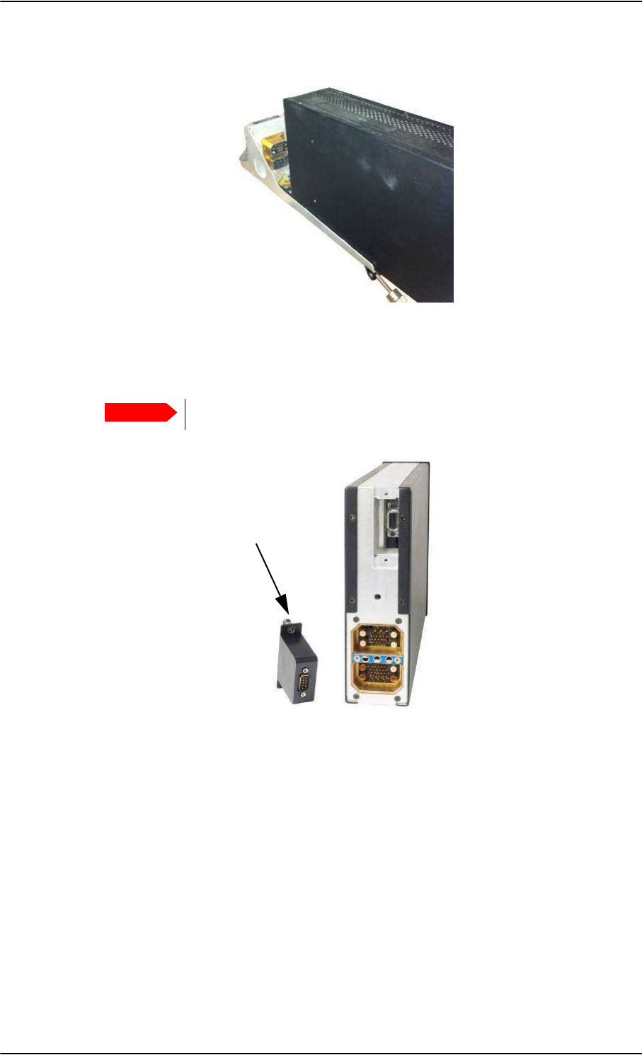
Exchanging LRUs
8-16 Chapter 8: Maintenance and troubleshooting 98-124743-F
3. Pull the LRU straight out from the tray by the handle. Be careful not to drop the unit.
Figure 8-9: Pull out the LRU
4. If the LRU has a Configuration Module (CM), unscrew it and pull it out from the rear of
the LRU.
Make sure that the Configuration Module is attached to the airframe.
Figure 8-10: Attach CM to the airframe
Re-installation
Follow the procedure above in reverse order. Make sure that the LRU is completely seated
against the mating A404 connector.
Important
Pull straight out!
Attach to
the airframe!

Troubleshooting
98-124743-F Chapter 8: Maintenance and troubleshooting 8-17
8.4.4 Removal and re-installation of the HPA
Use the same procedure as for the SDU and SBU. The only difference is that the HPA does
not have a Configuration Module.
Coax connectors TPA1 and TPA2: In case the cables for these are bent
too much there is a risk that the connectors are not aligned correctly with the
mating HPA connector. Make sure that there is no strain on the cables
connected to TPA1 and TPA2 on the tray side.
8.5 Troubleshooting
8.5.1 Status signalling
Built-In Test Equipment
The SDU and the SBU both provide a Built-In Test Equipment (BITE) function in order to
make fault diagnostics easy during service and installation.
The BITE test is performed during:
• Power On Self Test (POST), which is automatically performed each time the system is
powered on.
• Person Activated Self Test (PAST), which is initiated by pushing the Push To Test button
on the SDU front panel.
Also, during operation a Continuous Monitoring BITE function is performed.
Each LRU in the AVIATOR 700 system has its own BITE function but they are all controlled
and monitored by the SDU in the system.
Results from the BITE tests for the complete AVIATOR 700 system are shown as four digit
error codes. The two most significant digits represent the main group and are displayed on
the SDU front panel. The two least significant digits give further details. All four digits are
displayed in the 4-wire handset display together with more detailed information. The SBU
may report BITE error codes to the SDU. These SBU BITE codes inform you that there are
errors in the SBU. Use the SBU diagnostic report for further information on the SBU BITE
errors. To get further information about the BITE error codes relating to the SBU access the
web interface of the SBU.
Details on error messages after a POST or PAST for the SBU can be found in the event list of
the SBU, see Viewing the Event list, Event log and extended status of the SBU on page 8-
24.
Means of signalling
The AVIATOR 700 system provides various methods for signalling the status of the system.
•LEDs on the front panel of the SDU, SBU and the HPA are used to signal:
• Power on/off
• Logon
•F
ail/Pass
•The handset display in the Thrane & Thrane 4-Wire Handset is used to display
messages concerning:
Important

Troubleshooting
8-18 Chapter 8: Maintenance and troubleshooting 98-124743-F
• information from the services
• status information from the system to the user
• equipment errors.
•The MCDU display shows the same messages as the 4-Wire Handset display.
•The BITE display on the SDU is used to display BITE error codes. Refer to System
messages on page D-1.
Push to Test button on SDU and SBU
The SDU and SBU both have a hardware reset/test button placed on the front panel for
BITE purposes. Use the button on the SDU to reset both SDU and SBU and to activate a self
test (PAST).
Do not use the Push to Test button on the SBU. The SBU is reset
automatically when the SDU is reset.
Messages in the Thrane & Thrane 4-Wire Handsets
Two types of messages are displayed in the Thrane & Thrane 4-Wire Handsets.
• Cause codes are information from the services or status information from the system to
the user.
• BITE codes are information about errors in the equipment.
BITE codes are also shown in the BITE display of the SDU and in the display of the 4-Wire
Handset.
For further information and lists of the possible error codes, see the appendix System
messages on page D-1.
Messages in the MCDU display
The MCDU display shows the same messages as the 4-Wire Handset display.
BITE display on SDU
The two-digit 7-segment BITE display (green) is used for displaying BITE codes. Only the
two most significant digits of the four-digit BITE codes are shown in the SDU display.
For further information and a list of the BITE codes, refer to BITE Error codes on page D-
15.
Note
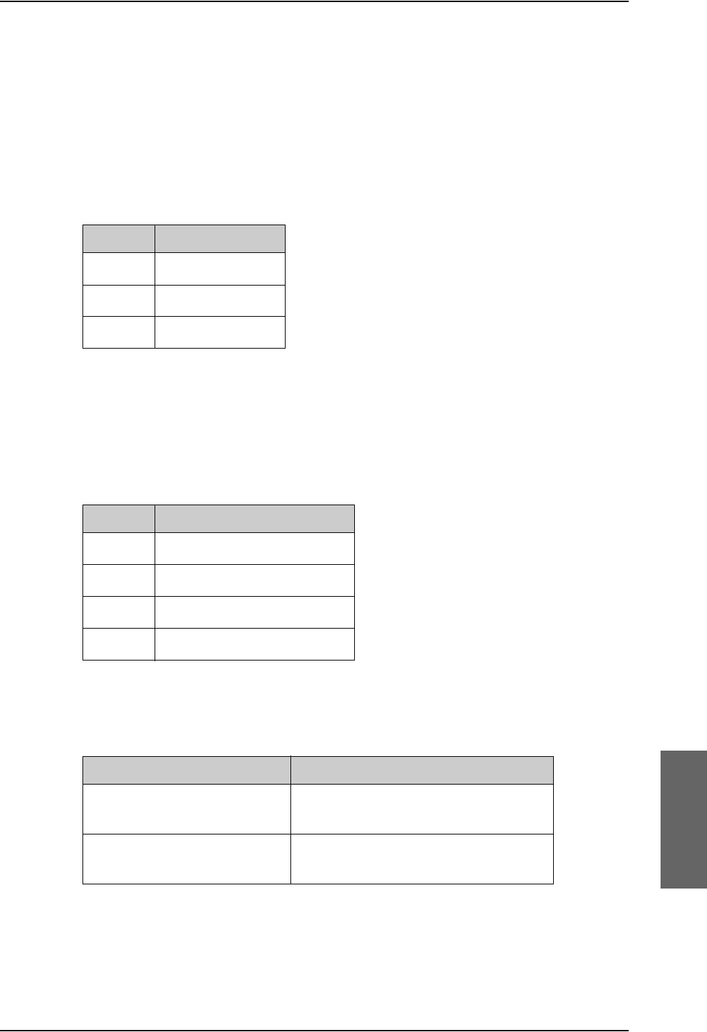
Troubleshooting
98-124743-F Chapter 8: Maintenance and troubleshooting 8-19
8.5.2 Status signalling with LEDs
LEDs on the SDU
During the power-up procedure all LEDs on the front plate are orange. If all 3 LEDs on the
front stay orange after power up, the software is corrupted.
Power LED
The function of the Power LED on the SDU is:
Logon LED (H+)
The Logon LED on the SDU shows the H+ logon status. The HSD logon status is only
signalled in the 4-Wire Handset.
The possible colors are listed below, with a short description of what they indicate:
Fail/Pass LED, SDU
The function of the Fail/Pass LED on the SDU is:
LED Color Description
Green Power OK
Orange Uploading software
Off No power
Table 8-1: Function of SDU Power
LED
LED Color Description
Red Acquiring satellite network
Orange Network synchronization
Green Network Logon
Off No acquired satellite/logged off
Table 8-2: Function of SDU Logon LED
Behavior Description
Steady red A fault which may degrade the system
operation is present in the system.
Alternating:
Short green / long pause
Power On Self Test (POST) or Person
Activated Self Test (PAST) in progress.
Table 8-3: Function of SDU Fail/Pass LED
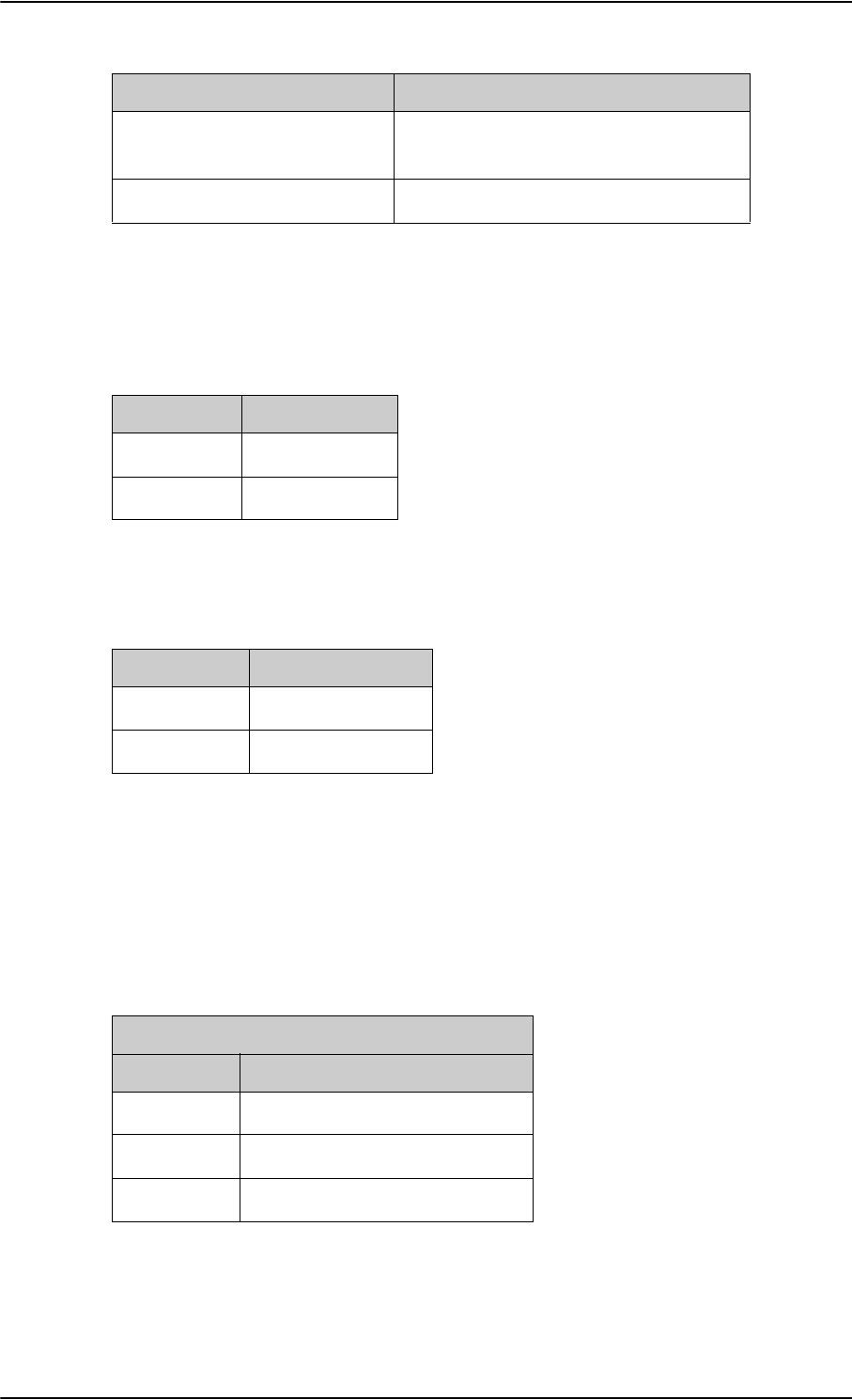
Troubleshooting
8-20 Chapter 8: Maintenance and troubleshooting 98-124743-F
LEDs on HPA
Power LED
The function of the Power LED on the HPA is:
Fail/Pass LED
The function of the Fail/Pass LED on the HPA is:
LEDs on SBU
During the power-up procedure all LEDs on the front plate are orange. If all 3 LEDs on the
front stay orange after power up, check that the wiring between the SDU BP 56 and SBU TP
8 is wired and that the system is configured as an AVIATOR 700 (see Set the System type
on page 6-49). If the wiring is good and the system is configured as an AVIATOR 700, the
SBU software is corrupted. Contact your local distributor for instructions how to proceed.
Alternating:
Long green/ short orange 0.5 Hz
No current failure, but a BITE failure /
warning is logged in the error log
Steady green No faults
Behavior Description
Table 8-3: Function of SDU Fail/Pass LED
Behavior Description
Green Power OK
Off No power
Table 8-4: Function of HPA Power LED
Behavior Description
Red Fail
Off No Faults
Table 8-5: Function of HPA Fail/Pass LED
Power LED on SBU
Behavior Description
Green Power OK
Orange During upstart procedure
Off No power
Table 8-6: Function of the SBU Power LED
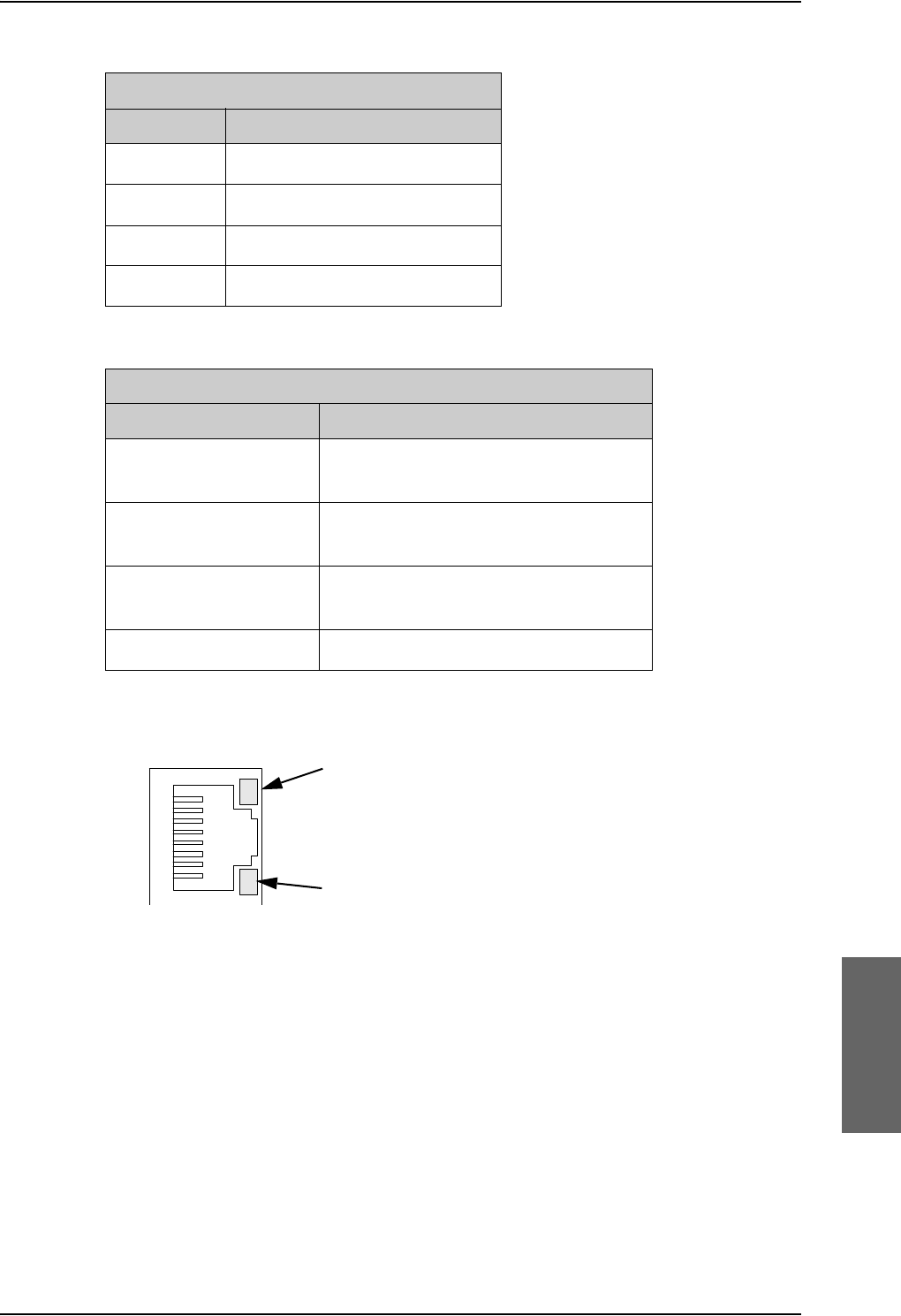
Troubleshooting
98-124743-F Chapter 8: Maintenance and troubleshooting 8-21
LEDs on maintenance connector
Figure 8-11: Function of the LEDs on the front maintenance connector
Logon LED on SBU
Behavior Description
Red Acquiring satellite network
Orange Network synchronization
Green Network logon
Off No acquired satellite/logged off
Table 8-7: Function of the SBU Logon LED
Fail/Pass LED on SBU
Behavior Description
Steady red A fault which may degrade the system
operation is present in the SBU
Flashing: short green/ long
pause
Power On Self Test (POST) or Person
Activated Self Test (PAST) in progress
Flashing: long green/ short
orange
No current failure, but a BITE failure /
warning is logged in the error log
Steady green No faults
Table 8-8: Function of the SBU Fail/Pass LED
LED Flashing yellow
Activity (data in/out)
LED Steady green
Link (correct connection)
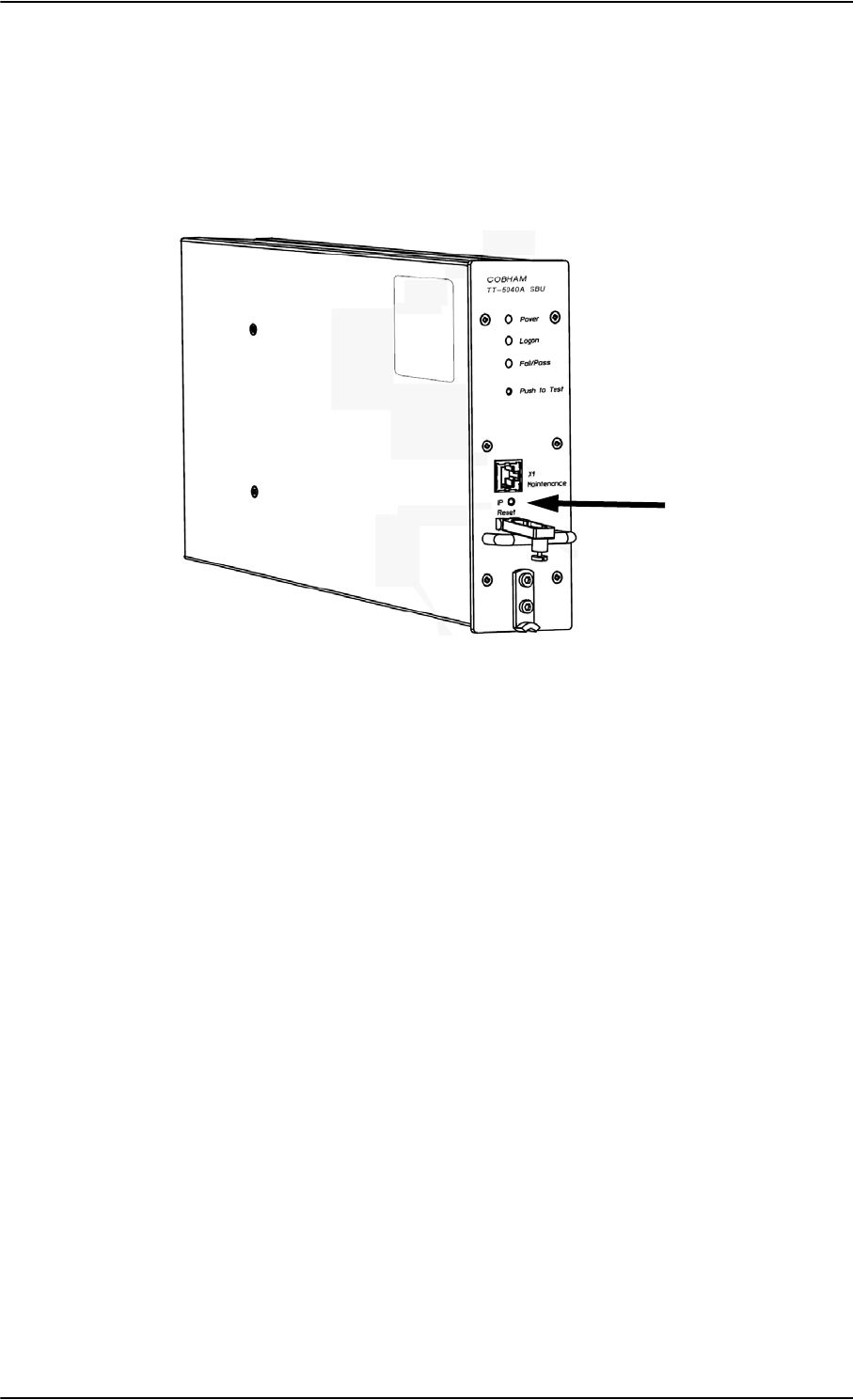
Troubleshooting
8-22 Chapter 8: Maintenance and troubleshooting 98-124743-F
8.5.3 IP Reset (Default) button on the SBU
The SBU has an IP Reset (Default) button next to the front LAN maintenance connector
below the metal cover. The button has two functions: To reset the terminal’s IP address and
netmask to the default value, 192.168.0.1 and to reset the terminal to factory default
settings.
Figure 8-12: IP Reset (Default) button on SBU front
The table on the next page describes how you can use the IP reset button.

Troubleshooting
98-124743-F Chapter 8: Maintenance and troubleshooting 8-23
Action Function
With the SBU running,
push the IP Reset
button normally.
Temporary reset to default values: The SBU’s IP address
and IP netmask are temporarily set to the default value (default
IP address: 192.168.0.1, default netmask: 255.255.255.0).
With this function, even if the IP address has been changed and
you do not remember the new IP address, you can still access
the web interface and see your current configuration. The
default value is not saved in the configuration, but is only valid
until next reboot.
With the terminal
running, push and hold
the IP Reset button for
30 seconds, until the
Power indicator on the
SBU front plate flashes
orange.
Reset to factory settings: The SBU restores factory settings
and reboots the system. All settings are reset to factory default,
incl. the IP address of the SBU and the administrator password.
Exception: The settings that are specific for the installation
are not reset. These are the settings on the pages:
• SETTINGS > System Type
• SETTINGS > RF Settings
• SETTINGS > External Systems
• SETTINGS > Flex
•ADMINISTRATOR > User permission > SMS
While the terminal is
booting, push and hold
the IP Reset button.
For service use only!
This firmware upload procedure is only to be used if the other
procedures fail due to missing or corrupted firmware. This
setup uploads software to the SBU from a TFTP server via the
LAN connection. The procedure is as follows:
1. Activate or install a TFTP server on a PC.
2. Locate the correct software image (xxx.dl) for the SBU and
place it in the TFTP server directory.
3. Rename the image to ttexp.dl.
4. Reconfigure the PC LAN interface to use the static address
192.168.0.2/255.255.255.0.
5. Power off the SBU.
6. Connect the PC LAN Interface to the SBU,
7. Push and hold down the Reset button.
8. Keep the Reset button pushed while powering on the SBU,
and through the next step.
9. Monitor the TFTP server window. When the upload starts
you can release the Reset button.
10. When the TFTP upload finishes the SBU boots up using the
new image.
Table 8-9: How to reset the IP address or the terminal software to default settings
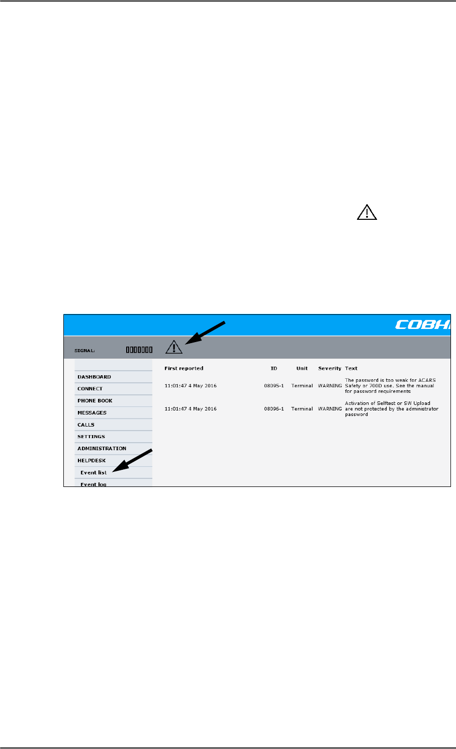
Troubleshooting
8-24 Chapter 8: Maintenance and troubleshooting 98-124743-F
8.5.4 Service log of the SDU
You use the Aero-SDU Configuration Program to generate a service log. The service log
contains all data necessary for troubleshooting the SDU, HPA and the satcom antenna.
Errors from the POST and PAST tests are recorded in the service log.
For instructions how to generate a service log see Generating a service log on page 8-5.
8.5.5 Viewing the Event list, Event log and extended status of the
SBU
Overview
When an event is registered, the web interface shows an event icon in the icon bar as
long as the event is active. The Event list only shows events that are currently active,
whereas the Event log shows the history of events that have occurred.
Event list
To view the event list, click the event icon from the icon bar at the top of the web interface,
or select HELPDESK > Event list from the left navigation pane.
Figure 8-13: Web interface: Help desk, Event list
The Event list page shows a detailed list of active events including the time of the first
occurrence, ID and severity of the event message, and a short text describing the error. For
a list of events with description, ID, explanation and remedy see List of SBU events on
page D-28.
Event log
The Event log shows the same information as the Event list, but also includes events that
occurred in the past and are no longer active. Additionally, it lists events of informational
character, describing normal phases of operation for the SBU. The event log holds
information of events registered in the SBU or antenna. The same events are also indicated
in the Antenna and Terminal LEDs on the SBU LED panel. The log includes the time of the
occurrence, a short description, location of the error etc. This information can help
troubleshooting errors in the system. You can see the event log in the web interface.
To view the Event log, select HELPDESK > Event log from the left navigation pane.
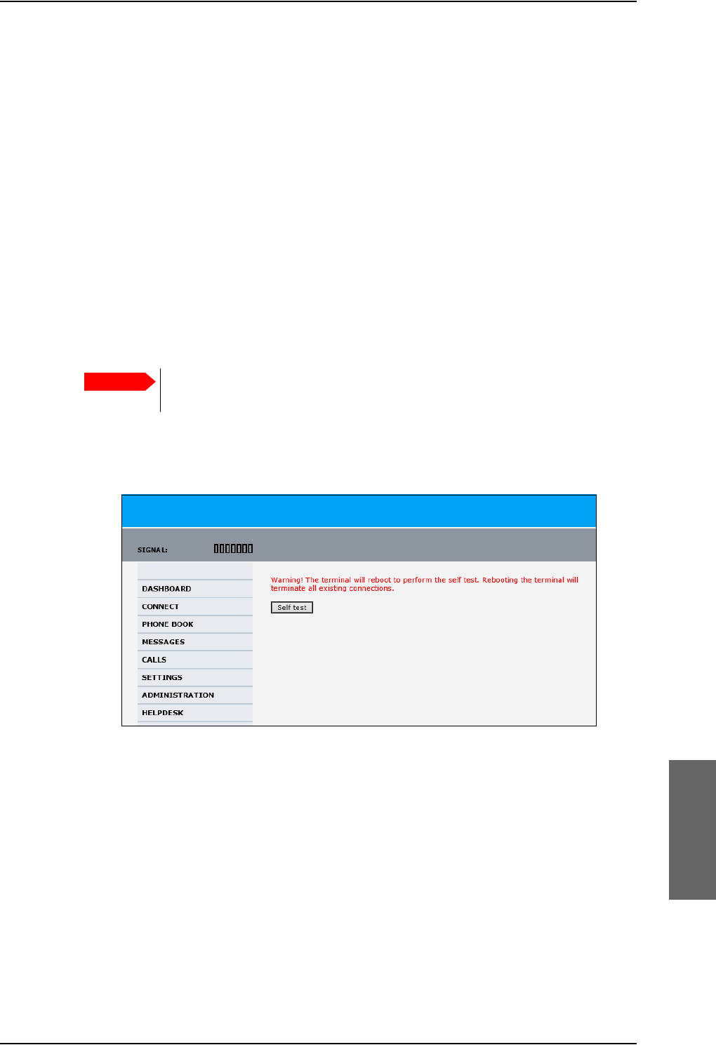
Troubleshooting
98-124743-F Chapter 8: Maintenance and troubleshooting 8-25
Extended status
The Extended Status page shows the following information:
• The antenna Product ID.
• The status of the connection to the air interface (IAI-2). This field should normally show
“Registered”, unless the system is still in the startup process.
• Ongoing data sessions (IP address) and connection status, e.g. Active or Suspended.
• Ongoing calls and their connection status.
To update the information on the Extended status page, click Refresh.
8.5.6 Self test of the SBU
The Self test performs system test on the AVIATOR 700 system, similar to the tests that are
performed during the Power On Self Test (POST).
To activate a Self test, do as follows:
1. Select HELPDESK > Self test.
Figure 8-14: Web interface: Help desk, Self test
2. Click Self test.
3. Click OK in the Warning dialog.
The SBU now performs a self test and resets the SBU.
Important
The SBU will reboot when performing the self test. All ongoing calls or data
sessions will be terminated.

Troubleshooting
8-26 Chapter 8: Maintenance and troubleshooting 98-124743-F
8.5.7 Initial troubleshooting
Overview
This section describes an initial check of the primary functions of the AVIATOR 700 system,
and provides some guidelines for troubleshooting, if one of the checks should fail.
Means available for troubleshooting
The following means are available for troubleshooting:
•LEDs and BITE display. Generally, if a fault occurs without any obvious reason, it is
always recommended to observe the LEDs and the BITE display. For information on the
LEDs and the BITE display, refer to Status signalling on page 8-17. For a list of all the
BITE codes and Cause codes, refer to the appendix System messages on page D-1.
•Web interface. For troubleshooting errors in the SBU, you may connect to the front
LAN interface on the SBU and use the web interface to inspect any alarm messages.
For information on the web interface refer to Built-in web interface for the SBU on
page 6-16.
•Low level commands. It may sometimes be necessary to use terminal commands for
debugging, using the front Maintenance port of the SDU. For information on how to use
the front port for debugging, see Using terminal commands on page F-1.
•Diagnostic report. You can generate a diagnostic report that can be used for
troubleshooting errors in the SBU of the AVIATOR 700 system. To generate the
diagnostic report, access the web interface and select HELPDESK. then click Generate
report. Save the report on your PC.
• To generate the service log, click the Service log button to the left in the Aero-SDU
Configuration Program. For information see Aero-SDU Configuration Program for the
SDU on page 6-2.
• Enclose the diagnostic report and the service log when requesting support.
Problem What to do
No connection to the
SBU maintenance
connector
Depending on the options in your system you might experience
limitations when using an Ethernet interface of the AVIATOR 700.
For systems without the built-in router option enabled, i.e. the
basic version or the version with Wireless option, note the
following limitation:
• To use the SBU Maintenance connector disconnect or switch
off any PC connected to another LAN interface of the SBU.
No GPS signal:
Interference from
satcom antenna on
GPS antenna
If the existing GPS antenna on board the aircraft does not provide
sufficient filtering of the satcom antenna signal to provide a
usable GPS signal, you must replace the existing GPS antenna with
a GPS antenna that has a satcom filter.
Registration for voice
or data not possible
In case the system cannot register properly for voice or data
service, check with your Service provider that the SIM card in the
Configuration module of the SBU is not blocked.
Table 8-10: Initial troubleshooting
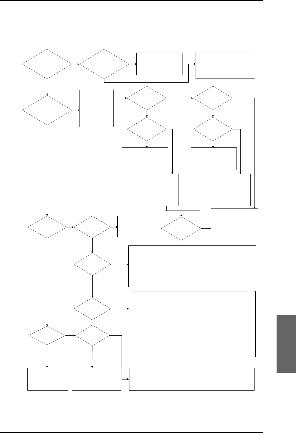
Troubleshooting
98-124743-F Chapter 8: Maintenance and troubleshooting 8-27
Check of LEDs
The below flow chart shows the initial check of the LEDs on the SDU, HPA and SBU.
Figure 8-15: Initial check of LEDs (1/2)
&KHFN
3RZHUFRQQHFWLRQV
&LUFXLW%UHDNHUV
Q2QLQSXW73
1R
1R
&KHFNIRUHUURU
FRGHVLQ
%,7(GLVSOD\
RQ6'8
+DQGVHW
0DLQWHQDQFH
SRUW
6HWORJRQSROLF\
WRDXWRPDWLFRU
ORJRQPDQXDOO\
&KHFN
/RJRQ&DXVHFRGHLQKDQGVHWRUPDLQWHQDQFHSRUW
+3$WUD\FRQQHFWRU
+3$FRUUHFWLQWUD\LQFO73QRWSXVKHGEDFN
7[5)FDEOHDQGFRQQHFWRUV
6LJQDOVWUHQJWK5HIHUWRWKHVHFWLRQDERXWVLJQDOVWUHQJWKLQWKH
8VHU0DQXDO,IORZFKHFNWKDWWKHDQWHQQDKDVOLQHRIVLJKWWR
WKHVDWHOOLWHDQGWKDWWKHQDYLJDWLRQGDWDDUHFRUUHFW
5[5)FDEOHDQGFRQQHFWRUV
6'8WUD\FRQQHFWRU
6'8FRUUHFWLQWUD\
$QWHQQDV\VWHPLQFO'/1$
,V,&$2DGGUHVVFRPPLVVLRQHG"
1R
1R
1R
&KHFN
6LJQDOVWUHQJWK5HIHUWRWKHVHFWLRQDERXWVLJQDOVWUHQJWKLQWKH
8VHU0DQXDO,IORZFKHFNWKDWWKHDQWHQQDKDVOLQHRIVLJKWWR
WKHVDWHOOLWHDQGWKDWWKHQDYLJDWLRQGDWDDUHFRUUHFW
5[5)FDEOHDQGFRQQHFWRUV
6'8WUD\FRQQHFWRU
6'8FRUUHFWLQWUD\
$QWHQQDV\VWHPLQFO'/1$
<HV
<HV
<HV
6'83RZHU/('
JUHHQ"
6'8)DLO3DVV/('
VWHDG\JUHHQ"
6'8/RJRQ
/('JUHHQ"
<HV
<HV
<HV
&KHFN
3RZHUFRQQHFWLRQV
&LUFXLW%UHDNHUV
Q2QLQSXW%3
+3$3RZHU
/('JUHHQ"
&RQWLQXHWR
&KHFNRI
(WKHUQHW,6'1
DQG+DQGVHWV
+3$UHODWHG
%,7("
&KHFN
3RZHUFRQQHFWLRQV
&LUFXLW%UHDNHUV
Q2QLQSXW73
6%83RZHU
/('JUHHQ"
6%8UHODWHG
%,7("
1R
<HV
1R
<HV
7URXEOHVKRRW
DFFRUGLQJWR%,7(
FRGH,I\RXDUHXQDEOH
WRUHVROYHWKHLVVXH
FDOO7KUDQH7KUDQH
&XVWRPHU6HUYLFH
1R
<HV
<HV
1R
&KHFN
+3$FRUUHFWLQWUD\
6'8WR+3$5)FDEOH
6'8+3$FRQWUROVLJQDOV
6'8%3%3DQG
+3$%3%3
&KHFN
6%8FRUUHFWLQWUD\
6'86%8FRQWUROVLJQDOV
6'8%3%3%3
DQG6%8737373
(UURUIRXQG" 1R
6'8/RJRQ
/('RII"
6'8/RJRQ
/('UHG"
6'8/RJRQ
/('RUDQJH"
&KHFN
6'8FRQILJXUHGDV
$9,$725V\VWHPLQ
$HUR6'8&3
1R
1R
&KHFN
,06,QXPEHULQ&RQILJXUDWLRQ0RGXOHDFWLYDWHG
6LJQDOVWUHQJWKLQZHELQWHUIDFHRUKDQGVHW
5)FDEOHVEHWZHHQ6%8DQGFRPELQHUVSOLWWHU
6%8/RJRQ
/('JUHHQ"
6%8)DLO
/('JUHHQ"
<HV
<HV
6'83RZHU/('
2UDQJH"
1R 6RIWZDUHFRUUXSWHG
5HORDGVRIWZDUHZLWK$HUR
6'8&33RZHURQ6'8
DIWHU´6WDUW´LVSUHVVHG
<HV
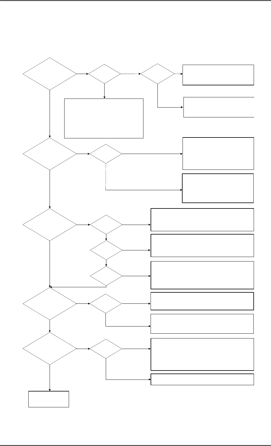
Troubleshooting
8-28 Chapter 8: Maintenance and troubleshooting 98-124743-F
Check of Ethernet, ISDN and handsets
After checking the LEDs, the user functions should be checked.
The below flow chart shows the initial check of Ethernet, ISDN and handsets.
Figure 8-16: Initial check of Ethernet, fax, 4-Wire Handsets and ISDN
&RQWLQXHWR
&KHFNRI)$;
&KHFN
3&KDVFRUUHFW,3DGGUHVV
3&FDQSLQJ6%8GHIDXOWJZ
<HV
1R
1R
(WKHUQHWZRUNLQJ"
ZLUHKDQGVHWV
ZRUNLQJ"
<HV
$FFHVVWR
6%8:HE"
<HV
1R (WKHUQHW
/LQN"
1R
<HV
&KHFN
:LULQJEHWZHHQ6%8DQG3&
3&HWKHUQHWVSHHGFRUUHFW
&KHFNRQ6%8
$31$FFHVV3RLQW1DPH
3URILOHVDQGIORZILOWHUV
6LJQDOVWUHQJWK!G%+]DWFDOO
6,0DFWLYDWHGIRUXVHGVHUYLFH
/RJIRUHUURUFRGHV
1R
,6'1ZRUNLQJ" 'LDOWRQH"
&KHFN
6%8VLJQDOVWUHQJWK
6HUYLFHDQGFDOOURXWLQJ
/RJIRUHUURU
<HV
1R
&KHFN
,QWHUIDFHHQDEOHG
([WHUQDOSRZHURQGHYLFH
:LULQJEHWZHHQ6%873
DQG,6'1GHYLFH
ZLUHKDQGVHWV
ZRUNLQJ"
,QWHUQDO
FDOO2.
1R
$LUWR
*1'2.
*1'WR
DLU2.
1R
1R
&KHFN
+DQGVHWSOXJJHGFRUUHFWO\LQWRFUDGOH
:LULQJIURPFUDGOHWR6'8
+DQGVHWFRQILJXUDWLRQLQ$HUR6'8&3
<HV
<HV
&KHFN
&DOOUHOHDVHFRGHGLVSOD\HGLQWKHKDQGVHW
ZKLOHPDNLQJDFDOO7URXEOHVKRRWDFFRUGLQJO\
&KHFN
'LDOHGQXPEHULVFRUUHFWDVVKRZQRQ
DFWLYDWLRQIRUP
+DQGVHWLVQRWLQKLELWHGE\IODSVRUVODWV
5RXWLQJLVFRUUHFWDVN\RXUVHUYLFHSURYLGHU
'LDOWRQH" 1R
&KHFN
+DQGVHWSOXJJHGFRUUHFWO\LQWRFUDGOH
:LULQJIURPFUDGOHWR6'86%8
1R
<HV &KHFN
(UURUWRQHLQKDQGVHWZKHQGLDOLQJ
&DOOUHOHDVHFRGHLQFDOOORJ
'DWD
$),6$&$56
&08ZRUNLQJ"
1R 6\VWHP
UHDG\
1R
&KHFN
&RQQHFWLRQEHWZHHQ6'8%3DQG
&08
&RQILJXUDWLRQLQ$HUR6'8&3&08$&$56
PDUNHG&RQQHFWHGDQGFRUUHFWVSHHG
VHOHFWHG
<HV
&KHFN,&$2QXPEHULVDFWLYDWHGIRU'DWD
<HV
<HV
<HV
<HV
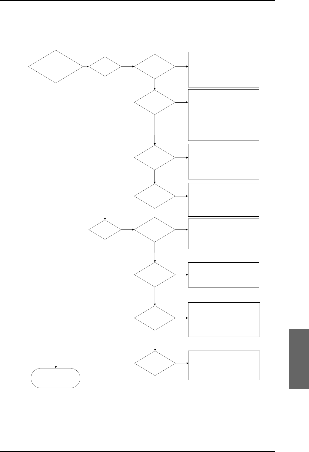
Troubleshooting
98-124743-F Chapter 8: Maintenance and troubleshooting 8-29
Check of fax
The below flow chart shows the initial check of the fax interfaces.
Figure 8-17: Initial check of Fax
&KHFN2.
<HV
1R
1R
&KHFN
&RQQHFWLRQIURPID[/LQHWR
6'8SRUW73RU
73
3RUWFRQILJXUHGDV´)D[´LQ
$HUR6'8&3
&KHFN
&RQQHFWLRQWRFRUUHFWSRUWRQ
6'8E\GLDOLQJRUIURP
DKDQGVHW
5LQJ3URILOHVFRUUHFWO\VHWXS
6HUYLFH3URYLGHUKDVV\VWHP
VHWXSIRU)$;RQ+DQGRQ
FRUUHFWSRUWVDPHDVDERYH
&KHFN
7KHID[PDFKLQHLVVHWIRU
RYHUVHDVPRGH
8VHDVSUHIL[
.+]DXGLRVHOHFWHGDV
RXWJRLQJVHUYLFH
&KHFN
7KHID[PDFKLQHLVVHWIRU
RYHUVHDVPRGH
7KHID[LVVHWWRSLFNXSDIWHU
WZRRUOHVVULQJV
<HV 1R
1R
<HV
1R
<HV
1R
<HV
)D[ZRUNLQJ" )D[RQ+" 'LDOWRQH"
5LQJLQJ"
)D[RQ
6%8"
6HQGLQJ2.
$LUWR*1'
5HFHLYH2.
*1'WR$LU
&KHFN
7KHID[PDFKLQHLVVHWIRU
RYHUVHDVPRGH
8VHDVSUHIL[
)D[VWDUWXSWUDQVPLWVSHHG
ELWVUHFRPPHQGHG
&KHFN
7KHID[PDFKLQHLVVHWIRU
RYHUVHDVPRGH
7KHID[LVVHWWRSLFNXSDIWHU
WZRRUOHVVULQJV
7KHID[LVLQ)$;PRGH
<HV
1R
1R
6HQGLQJ2.
$LUWR*1'
5HFHLYH2.
*1'WR$LU
<HV
&KHFN
3RUWVLQWHUIDFHHQDEOHW
&RQQHFWLRQIURPID[/LQHWR
6%873RU73
&KHFN
6HUYLFH3URYLGHUKDVV\VWHP
VHWXSIRU)$;RQ
6ZLIW%URDGEDQG
1R
1R
<HV
'LDOWRQH"
5LQJLQJ"
<HV
<HV

Returning units for repair
8-30 Chapter 8: Maintenance and troubleshooting 98-124743-F
8.6 Returning units for repair
Should your Cobham SATCOM product fail, please contact your dealer or installer, or the
nearest Cobham SATCOM partner. You will find the partner details on
www.cobham.com/satcom/service-and-support/cobham-satcom-service-and-support
where you also find the Cobham SATCOM Self Service Center web-portal, which may help
you solve the problem. Your dealer, installer or Cobham SATCOM partner will assist you
whether the need is user training, technical support, arranging on-site repair or sending the
product for repair. Your dealer, installer or Cobham SATCOM partner will also take care of
any warranty issue.
Repackaging requirements
Should you need to send the product for repair, please read the below information before
packing the product.
The shipping carton has been carefully designed to protect the AVIATOR 700 and its
accessories during shipment. This carton and its associated packing material should be used
when repacking for shipment. Attach a tag indicating the type of service required, return
address, part number and full serial number. Mark the carton FRAGILE to ensure careful
handling.
Correct shipment is the customer’s own responsibility.
If the original shipping carton is not available, the following general instructions should be
used for repacking with commercially available material.
1. Wrap the defective unit in heavy paper or plastic. Attach a tag indicating the type of
service required, return address, part number and full serial number.
2. Use a strong shipping container, e.g. a double walled carton.
3. Protect the front- and rear panel with cardboard and insert a layer of shock-absorbing
material between all surfaces of the equipment and the sides of the container.
4. Seal the shipping container securely.
5. Mark the shipping container FRAGILE to ensure careful handling.
Failure to do so may invalidate the warranty.
8.7 Disposal of electrical and electronic equipment
Old electrical and electronic equipment marked with this symbol can contain
substances hazardous to human beings and the environment. Never dispose
these items together with unsorted municipal waste (household waste). In
order to protect the environment and ensure the correct recycling of old
equipment as well as the re-utilization of individual components, use either public
collection or private collection by the local distributor of old electrical and electronic
equipment marked with this symbol.
Contact the local distributor for information about what type of return system to use.
Note
Appendices

98-124743-F A-1
Appendix A
Equipment specifications A
A.1 Introduction
Important note!
The information, drawings, and wiring diagrams contained in this manual are intended as a
reference for engineering planning only. It is the installer’s responsibility to compose
installation drawings specific to the aircraft.
In this appendix you find equipment specifications for the following units:
•TT-5035A Satellite Data Unit (SDU)
•TT-5014A High Power Amplifier (HPA)
•TT-5040A SwiftBroadband Unit (SBU)
•TT-5040A-004 WLAN antenna
•TT-5038A-002 Tx Coupler
•TT-5038A-003 Rx Power Splitter
•TT-5620A 4-Wire Handset
•TT-5622A 4-Wire Cradle
•TT-5621B 2-Wire Handset
•TT-5622B 2-Wire Cradle
For specifications of the antenna please see the documentation provided with the antenna.
For equipment drawings of the AVIATOR Wireless Handset and Cradle see
AVIATOR Wireless Handset and Cradle Installation & Maintenance Manual
(98-129600).
Note
Cables and connectors and DLNA are not included.
Note

AVIATOR 700 system components
A-2 Appendix A: Equipment specifications 98-124743-F
A.2 AVIATOR 700 system components
A.2.1 TT-5035A Satellite Data Unit (SDU)
Specification with TT-5035A-001 Configuration Module (CM) mounted.
Characteristics Specification
Dimensions
(L x W x H)
ARINC 404A 3/8 ATR short, 3 MCU
320.5 mm x 193.5 mm x 90.4 mm
(12.62” x 7.62” x 3.56”)
Weight 3.5 kg ±0.1 kg (7.72 lbs ±0.22 lbs)
incl. Configuration Module
Mounting Mount in an ARINC 404A 3/8 ATR short tray in a
temperature controlled location.
Forced cooling is not recommended.
Supply Voltage
Power Hold-up
Nominal: +28.0 V DC
Voltage range
continuous operation: +20.5 V DC to 32.2 V DC
short time operation: +18.0 V DC to 32.2 V DC
5 ms. fully operational, 200 ms. Power Save Mode.
Power Consumption Absolute max power consumptiona: 46.5 W
(Heat dissipation: 27 W).
Typical operating power consumption (3 channels
transmitting, one 4-wire handset): 30 W
(Heat dissipation: 25 W).
Typical stand-by power consumption (no transmitting, one
4-wire handset): 25 W (Heat dissipation: 22 W).
Inrush current:
0-2 ms: Iin < 28 A
2 ms: Iin < 26 A
5 ms: Iin < 17 A
10 ms: Iin < 5.5 A
50 ms: Iin < 4.4 A
50 ms ->: Normal operation
Table A-1: General specifications for SDU

AVIATOR 700 system components
98-124743-F Appendix A: Equipment specifications A-3
Connectors Rear: ARINC 404A
Front: SUB-D 15 Female.
Operating Temperature
Ground Survival
Temperature
-25 C to +55 C
-55 C to +85 C
Altitude 55000 ft
Environmental Categories Refer to Environmental Qualification form in Satellite Data
Unit on page B-2 in Appendix B.
a. Includes 4 x 4-wire handsets, 2 x 2-wire handsets and 4 ISDN phones.
Characteristics Specification
Table A-1: General specifications for SDU

AVIATOR 700 system components
A-4 Appendix A: Equipment specifications 98-124743-F
A.2.2 TT-5014A High Power Amplifier (HPA)
Characteristics Specification
Dimensions
(L x W x H)
ARINC 404A 3/8 ATR short, 3 MCU
320.5 mm x 193.5 mm x 93.0 mm
(12.62” x 7.79” x 3.66”)
Weight 5.1 kg ±0.2 kg (11.24 lbs ±0.44 lbs)
Mounting Can be installed in a non-temperature controlled location.
The HPA is designed with built-in forced cooling. Do not
block the cooling air holes. Minimum clearance top and
bottom: 1” (25 mm)
Mount in ARINC 404A 3/8 ATR short tray with oval cut-out
as shown in Figure 3-16: Outline Drawing: Tray for
SDU and HPA..
Supply Voltage
Power Hold-up
Nominal: +28.0 V DC
Voltage range,
continuous operation: +20.5 V DC to 32.2 V DC
short time operation: +18.0 V DC to 32.2 V DC
5 ms. fully operational, 200 ms. Power Save Mode.
Power Consumption Absolute max power consumption: 235 W
(Heat dissipation: 185 W).
Typical operating power consumption (4 channels
transmitting): 130 W (Heat dissipation: 110 W).
Typical standby power consumption (no transmitting):
40 W (Heat dissipation: 40 W).
Inrush current:
0-10ms: Iin < 55A
10ms: Iin < 6A
10-30ms: Iin < 20A
30ms: Iin < 15A
40ms: Iin < 10A
60ms: Iin < 4A
60ms ->: Normal operation
Composite Output Power 37.4 W (Burst Mode)
30.0 W (Continuous Mode)
Table A-2: General specifications for HPA

AVIATOR 700 system components
98-124743-F Appendix A: Equipment specifications A-5
Connectors Rear: ARINC 404A
Operating Temperature
Ground Survival
Temperature
-55 C to +70 C
-55 C to +85 C
Altitude 55000 ft
Environmental Categories Refer to Environmental Qualification form in High Power
Amplifier on page B-5 in Appendix B.
Characteristics Specification
Table A-2: General specifications for HPA

AVIATOR 700 system components
A-6 Appendix A: Equipment specifications 98-124743-F
A.2.3 TT-5040A SwiftBroadband Unit (SBU)
Characteristics Specification
Dimensions
(L x W x H)
ARINC 404A 1/4 ATR short
320.5 mm x 193.5 mm x 57.15 mm (12.62” x 7.62” x 2.25”)
Weight 2.8 kg ±0.1 kg (6.2 lbs ±0.22 lbs) including TT-5040-001 CM
Mounting Mount in an ARINC 404A 1/4 ATR short tray in a temperature controlled
location.
Forced cooling is not required and not recommended.
Supply Voltage
Power Hold-up
Nominal: +28.0 V DC
Voltage range,
continuous operation: +20.5 V DC to 32.2 V DC
short time operation: +18.0 V DC to 32.2 V DC
200 ms. Fully operational: 5 ms.
Typical Power
Consumption (idle) (SBU &
CM)
17 W
Total Maximum Power
Consumption (SBU & CM)
25 W
Maximum Heat Dissipation
(SBU & CM)
<25 W
Connectors Rear: ARINC 404A
Front: RJ45 Female.
Operating Temperature
Ground Survival
Temperature
-25 °C to +55 °C
-55 °C to +85 °C
Altitude Non pressurized (Cat. F1): 55,000 ft
Pressurized (Cat. A1): 15,000 ft
Decompression (Cat. A1): 55,000 ft
Overpressure (Cat. A1): -15,000 ft
Relative humidity 95% non-condensing at +50°C
Environmental Categories Refer to Environmental Qualification form in SwiftBroadband unit (SBU)
on page B-7 in Appendix B.
Table A-3: Equipment specifications for TT-5040A SBU

AVIATOR 700 system components
98-124743-F Appendix A: Equipment specifications A-7
A.2.4 TT-5040A-004 WLAN antenna
Characteristics Specification
Dimensions (L x W x H) 12 mm x 119 mm x 13 mm (0.48” x 4.7” x 0.5”)
Weight 28.3 g (1 ounce)
Mounting For mounting instructions for WLAN antennas see Figure 5-
3: Mounting two WLAN antennas for optimum performance in
WLAN antennas on page 5-8.
Connector Male TNC
Operating Temperature
Ground Survival
Temperature
-40 C to +71 C
-55 C to +85 C
Altitude Pressurized (Cat. A1): 15,000 ft
Decompression (Cat. A1): 45,000 ft
Overpressure (Cat. A1): -15,000 ft
Relative humidity 95% non-condensing at +50°C
Cable type Plenum, RG-316U coaxial
Cable length (including
connector)
7.5” ± 0.25” (190.5 ±6.4 mm)
Table A-4: Equipment specifications for WLAN antenna

AVIATOR 700 system components
A-8 Appendix A: Equipment specifications 98-124743-F
A.2.5 TT-5038A-002 Tx Coupler
Characteristics Specification
Dimensions
(L x W x H)
106.6 mm x 57.1 mm x 22.4 mm
(4.20” x 2.25” x 0.88”)
including connectors.
Weight 230 g ±10 g (0.50 lbs ±0.02 lbs)
Mounting Can be mounted in an unpressurized but temperature
controlled location.
Connectors 3 x N-connector, Female.
Operating Temperature
Ground Survival
Temperature
-25 C to +55 C
-55 C to +85 C
Altitude 55000 ft
Environmental Categories Refer to Environmental Qualification form in Tx Coupler
and Rx Power Splitter on page B-9 in Appendix B.
Table A-5: General specifications for Tx Coupler
AVIATOR 700 system components
98-124743-F Appendix A: Equipment specifications A-9
A.2.6 TT-5038A-003 Rx Power Splitter
Characteristics Specification
Dimensions
(L x W x H)
86.8 mm x 50.8 mm x 19.1 mm
(3.42” x 2.00” x 0.75”)
including connectors.
Weight 146 g ±10 g (0.32 lbs ±0.02 lbs)
Mounting If the Rx Power Splitter is to be mounted on a flat surface, mount it on a 3
mm mounting plate to provide enough space for mounting of the
connectors.
Can be mounted in an unpressurized but temperature controlled location.
Connectors 3 x N-connector, Female.
Built-in DC-block on the HSU (SBU) port.
Operating Temperature
Ground Survival
Temperature
-25 C to +55 C
-55 C to +85 C
Altitude 55000 ft
Environmental Categories Refer to Environmental Qualification form in Tx Coupler and Rx Power
Splitter on page B-9 in Appendix B.
Table A-6: General specifications for Rx Power Splitter

AVIATOR 700 handsets and cradles
A-10 Appendix A: Equipment specifications 98-124743-F
A.3 AVIATOR 700 handsets and cradles
A.3.1 TT-5620A 4-Wire Handset
Note
For specifications of the AVIATOR Wireless Handset see AVIATOR Wireless
Handset and Cradle Installation & Maintenance Manual (part number: 98-
129600)
Characteristics Specification
Dimensions (L x W x H) 200.0 mm x 52.0 mm x 31.5 mm
(7.87” x 2.05” x 1.24”)
Weight 0.31 kg ±50 g (0.68 lbs ±0.11 lbs) incl. cable.
Mounting Mount in a pressurized and temperature controlled
location.
Supply Voltage +28 V DC, provided by SDU via Handset Cradle.
Power Consumption Max. 3.5 W for handset and cradle (included in SDU power
consumption).
Operating Temperature
Ground Survival
Temperature
-25 C to +55 C
-40 C to +80 C
Altitude 55000 ft
Environmental Categories Refer to Environmental Qualification form in 4-Wire
Handset and 4-Wire Cradle on page B-11 in Appendix B.
Table A-7: General specifications for 4-Wire Handset

AVIATOR 700 handsets and cradles
98-124743-F Appendix A: Equipment specifications A-11
A.3.2 TT-5622A 4-Wire Cradle
Characteristics Specification
Dimensions (L x W x H) 160.5 mm x 61.0 mm x 28.4 mm
(6.30” x 2.40” x 1.12”)
Weight 0.27 kg ±50 g (0.60 lbs ±0.11 lbs) incl. connector cable.
Mounting Mount in a pressurized and temperature controlled
location.
Supply Voltage +28 V DC, provided by SDU.
Power Consumption See TT-5620A 4-Wire Handset on page A-10.
Operating Temperature
Ground Survival
Temperature
-25 C to +55 C
-40 C to +80 C
Altitude 55000 ft
Environmental Categories Refer to Environmental Qualification form in 4-Wire
Handset and 4-Wire Cradle on page B-11 in Appendix B.
Table A-8: General specifications for 4-Wire Cradle
AVIATOR 700 handsets and cradles
A-12 Appendix A: Equipment specifications 98-124743-F
A.3.3 TT-5621B 2-Wire Handset
A.3.4 TT-5622B 2-Wire Cradle
Characteristics Specification
Dimensions (L x W x H) 200.0 mm x 52.0 mm x 31.5 mm (7.87” x 2.05” x 1.24”)
Weight 0.22 kg ±50 g (0.49 lbs ±0.11 lbs) incl. cable.
Mounting Mount in a pressurized and temperature controlled location.
Power consumption Max. 750 mW for handset and cradle (included in SBU
power consumption).
Operating Temperature
Ground Survival
Temperature
-25 C to +55 C
-40 C to +80 C
Altitude 55,000 ft
Environmental Categories Refer to Environmental Qualification form in 2-Wire
Handset and 2-Wire Cradle on page B-13 in Appendix B.
Table A-9: Equipment specifications for 2-Wire Handset
Characteristics Specification
Dimensions (L x W x H) 160.5 mm x 61.0 mm x 28.4 mm (6.30” x 2.40” x 1.12”)
Weight 0.20 kg ±50 g (0.43 lbs ±0.11 lbs)
incl. connector cable.
Mounting Mount in a pressurized and temperature controlled location.
Power consumption See TT-5621B 2-Wire Handset on page A-12.
Operating Temperature
Ground Survival
Temperature
-25 C to +55 C
-40 C to +80 C
Altitude 55,000 ft
Environmental Categories Refer to Environmental Qualification form in 2-Wire
Handset and 2-Wire Cradle on page B-13 in Appendix B.
Table A-10: Equipment specifications for 2-Wire Cradle

98-124743-F B-1
Appendix B
DO-160 specifications B
B.1 General
B.1.1 Certifying agency
Approval of the installation of the AVIATOR 700 system is not authorized by this
installation manual. Acceptance for the installation and use of the AVIATOR 700 system
and its associated components must be obtained through the appropriate offices of the
FAA or other certifying agency. It is recommended that all proposed installations be
coordinated with the local jurisdiction of the FAA or other certifying agency prior to
performing the installation.
B.1.2 Environmental Qualification Forms
The Environmental Qualification Forms list the environmental categories under which all
Cobham SATCOM components of the AVIATOR 700 system are approved.
Please refer to RTCA DO-160D/E for further details on the following Environmental
Qualification Forms.

AVIATOR 700 system components
B-2 Appendix B: DO-160 specifications 98-124743-F
B.2 AVIATOR 700 system components
B.2.1 Satellite Data Unit
T&T Part Number: 405035A (AVIATOR 700) or 405035A-THD (AVIATOR 700D)
DO-160D string: [(A1)(F1)X]CAB[(S2B2)(SM)]EXXXXXZ[A()B]A[A()B]Z[RR]M[A3E3]XXA
RTCA/DO-160D Change Numbers
Change
Number Date of Issue Title Section
Change No. 1 Dec. 14, 2000 Vibration
Radio Frequency Susceptibility
8.0
20.0
Change No. 2 June 12, 2001 Power Input
Audio Frequency Conducted Susceptibility - Power Inputs
16.0
18.0
Table B-1: RTCA/DO-160D Change Numbers, SDU
Conditions DO-160D Cat. Comments
Temperature and Altitude 4.0 A1
and F1
Installation in controlled temperature
locations and inside or outside
pressurized locations.
Low Temperature 4.5.1 Min. operating low temperature: -25°C
High Temperature 4.5.2 & 4.5.3 Max. operating high temperature: +55°C
In-Flight Loss of Cooling 4.5.4 X Forced cooling is not recommended.
Altitude 4.6.1 Max. altitude: 55000 ft
Decompression 4.6.2 Decompression at 55000 ft
Overpressure 4.6.3 Overpressure at -15000ft
Temperature Variation 5.0 C Installation within controlled temperature
locations: 2°/min.
Humidity 6.0 A Standard Humidity: 95% relative humidity
at 38°C to 50°C for 48 hours.
Installation within environmentally
controlled zones.
Operational Shocks and Crash
Safety
7.0 B Equipment tested to: Standard
operational shocks and crash safety.
Table B-2: Environmental Qualification Form for SDU

AVIATOR 700 system components
98-124743-F Appendix B: DO-160 specifications B-3
Vibration 8.0 S2B2
SM
Standard random vibration:
Aircraft type: Fixed wing. Turbojet or
turbofan engines.
Standard sinusoidal vibration:
Aircraft type: Fixed wing. Reciprocating or
turbo propeller engines.
Aircraft zone: Instrument panel, console
or equipment rack.
Explosion Proofness 9.0 E
Waterproofness 10.0 X No test required
Fluids Susceptibility 11.0 X No test required
Sand and Dust 12.0 X No test required
Fungus Resistance 13.0 X No test required
Salt Spray 14.0 X No test required
Magnetic Effect 15.0 Z Magnetic deflection distance: < 0.3 m
Power Input 16.0 A()B Power supply: +28 V DC.
Reconnection of voice and data calls is
not required, if a power interrupt less than
200 ms occurs during transfer of power
sources.
Voltage Spike 17.0 A
Audio Frequency
Conducted Susceptibility -
Power Inputs
18.0 A()B
Induced Signal Susceptibility 19.0 Z Equipment intended for operation in
systems where interference-free
operation is required.
Radio Frequency Susceptibility 20.0 RR High Intensity Radiated Field (HIRF)
associated with normal environment.
Emission of Radio Frequency
Energy
21.0 M
Conditions DO-160D Cat. Comments
Table B-2: Environmental Qualification Form for SDU (Continued)

AVIATOR 700 system components
B-4 Appendix B: DO-160 specifications 98-124743-F
B.2.2 Configuration Module for SDU
T&T Part Number: 405035A-001
DO-160D string: Please refer to the section Satellite Data Unit on page B-2, as the
Configuration Module is an integral part of the SDU during normal operation and tests.
Lightning Induced Transient
Susceptibility
22.0 A3E3 Equipment and wiring in moderately
exposed environment in an all metal
airframe.
The Configuration Module is an
integrated part of the SDU, and so the pin
injection tests are not required for the
Configuration Module interface.
Lightning Direct Effects 23.0 X No test required
Icing 24.0 X No test required
Electrostatic Discharge (ESD) 25.0 A Operation, installation and repair in an
aerospace environment.
Conditions DO-160D Cat. Comments
Table B-2: Environmental Qualification Form for SDU (Continued)

AVIATOR 700 system components
98-124743-F Appendix B: DO-160 specifications B-5
B.2.3 High Power Amplifier
T&T Part Number: 405014A (AVIATOR 700) or 405014A-THD (AVIATOR 700D)
DO-160D string: [(A2)(F2)Z]BBB[SCL]EXXXXXZ[A()B]A[A()B]Z[RR]M[A3E3]XXA
RTCA/DO-160D Change Numbers
Change Number Date of Issue Title Section
Change No. 1 Dec. 14, 2000 Vibration
Radio Frequency Susceptibility
8.0
20.0
Change No. 2 June 12, 2001 Power Input
Audio Frequency Conducted Susceptibility - Power Inputs
16.0
18.0
Table B-3: RTCA/DO-160D Change Numbers, HPA
Conditions DO-160D Cat. Comments
Temperature and Altitude 4.0 A2 and
F2
Installation in non-controlled
temperature locations and inside or
outside pressurized locations.
Low Temperature 4.5.1 Min. operating low temperature: -55°C
High Temperature 4.5.2 & 4.5.3 Max. operating high temperature: +70°C
In-Flight Loss of Cooling 4.5.4 Z Continuous operation at 40°C, tested
with internal fan turned off.
Use the recommended tray and leave at
least 1 inch (25 mm) of free space above
and below the HPA, to allow free airflow.
The HPA is overheat protected.
External forced cooling is not
recommended.
Altitude 4.6.1 Max. altitude: 55000 ft
Decompression 4.6.2 Decompression at 55000 ft
Overpressure 4.6.3 Overpressure at -15000 ft
Temperature Variation 5.0 B Installation within non-temperature-
controlled location: 5°C/min.
Humidity 6.0 B Severe humidity: 95% relative humidity
at 38°C to 65°C for 240 hours.
Installation within non-environmentally
controlled zones.
Operational Shocks and Crash
Safety
7.0 B Equipment tested to: Standard
operational shocks and crash safety.
Table B-4: Environmental Qualification Form for HPA

AVIATOR 700 system components
B-6 Appendix B: DO-160 specifications 98-124743-F
Vibration 8.0 SCL Standard sinusoidal and random
vibration:
Aircraft type: Fixed wing. Turbojet,
turbofan, reciprocating or turbo propeller
engines.
Aircraft zone: Fuselage
Explosion Proofness 9.0 E
Waterproofness 10.0 X No test required
Fluids Susceptibility 11.0 X No test required
Sand and Dust 12.0 X No test required
Fungus Resistance 13.0 X No test required
Salt Spray 14.0 X No test required
Magnetic Effect 15.0 Z Magnetic deflection distance: < 0.3 m
Power Input 16.0 A()B Power supply: +28 V DC.
Reconnection of voice and data calls is
not required, if a power interrupt less
than 200 ms occurs during transfer of
power sources.
Voltage Spike 17.0 A
Audio Frequency Conducted
Susceptibility - Power Inputs
18.0 A()B
Induced Signal Susceptibility 19.0 Z Equipment intended for operation in
systems where interference-free
operation is required.
Radio Frequency Susceptibility 20.0 RR High Intensity Radiated Field (HIRF)
associated with normal environment.
Emission of Radio Frequency
Energy
21.0 M
Lightning Induced Transient
Susceptibility
22.0 A3E3 Equipment and wiring in moderately
exposed environment in an all metal
airframe.
Lightning Direct Effects 23.0 X No test required
Icing 24.0 X No test required
Electrostatic Discharge (ESD) 25.0 A Operation, installation and repair in an
aerospace environment.
Conditions DO-160D Cat. Comments
Table B-4: Environmental Qualification Form for HPA (Continued)

AVIATOR 700 system components
98-124743-F Appendix B: DO-160 specifications B-7
B.2.4 SwiftBroadband unit (SBU)
T&T Part Number: 405040A (AVIATOR 700) or 405040A-THD (AVIATOR 700D)
DO-160E string: [(A1)(F1)X]CAB[SB2M]ExxxxxZ[AB]A[RB][ZC][RR]M[A3J33]XXAX
Conditions DO-160E Cat. Comments
Temperature and Altitude 4.0 A1, F1 Installation in temperature controlled areas
and inside or outside pressurized locations.
Low Temperature 4.5.1 & 4.5.2 Short time operating low is -40°C. Unit is
active, but inoperable until the unit
temperature is > -30°C.
Min. operational temperature is -25°C.
High Temperature 4.5.3 & 4.5.4 Short time operating high (30 min.): +70°C
Max. operating high temperature is +55°C
In-Flight Loss of Cooling 4.5.5 X Forced cooling is not required and not
recommended.
Altitude 4.6.1 Max. altitude: 55000 ft
Decompression 4.6.2 Decompression test at 55000 ft
Overpressure 4.6.3 Overpressure at -15000 ft
Temperature Variation 5.0 C Installation within temperature controlled
areas: 2°C/min.
Humidity 6.0 A Standard Humidity: 95% relative humidity
at 38°C to 50°C for 48 hours.
Installation within environmentally
controlled zones
Operational Shocks and Crash
Safety
7.0 B Equipment tested to: Standard operational
shock and crash safety.
Vibration 8.0 S, B2,
M
Equipment tested without shock mounts to
Category S, Curve B2 and Curve M.
Explosion Proofness 9.0 E Not hermetically sealed equipment
Waterproofness 10.0 X No test required
Fluids Susceptibility 11.0 X No test required
Sand and Dust 12.0 X No test required
Fungus Resistance 13.0 X No test required
Table B-5: Environmental Qualification Form for SBU

AVIATOR 700 system components
B-8 Appendix B: DO-160 specifications 98-124743-F
Salt Spray 14.0 X No test required
Magnetic Effect 15.0 Z Magnetic deflection distance: < 0.3 m
Power Input 16.0 AB Power supply: +28 V DC.
Reconnection of voice and data calls is not
required, if a power interrupt less than 200
ms occurs during transfer of power sources.
Voltage Spike 17.0 A Power supply: +28 V DC.
Audio Susceptibility 18.0 RB Power supply: +28 V DC.
Induced Susceptibility 19.0 ZC Equipment intended for operation in
systems where interference-free operation
is required.
Radio Frequency Susceptibility 20.0 RR High Intensity Radiated Field (HIRF)
associated with normal environment.
Emission of Radio Frequency
Energy
21.0 M Installation in areas with significant
electromagnetic apertures.
Lightning Induced Transient
Susceptibility
22.0 A3J33 Equipment and wiring in moderately
exposed environment in an all metal
airframe.
The Configuration Module is an integrated
part of the SBU, and so the pin injection
tests are not required for the Configuration
Module interface.
Lightning Direct Effects23.0 XNo test required
Icing 24.0 X No test required
Electrostatic Discharge ESD 25.0 A Operation, installation and repair in an
aerospace environment.
Fire, Flammability 26.0 X Equipment is tested according to FAR 25
Airworthiness Standards: Transport
Category Airplanes, Paragraph 25.853(a)
and Appendix F - Part I (a)(1)(ii) and
Paragraph 25.869(a)(4) and Appendix F -
Part I (a)(3).
Conditions DO-160E Cat. Comments
Table B-5: Environmental Qualification Form for SBU (Continued)
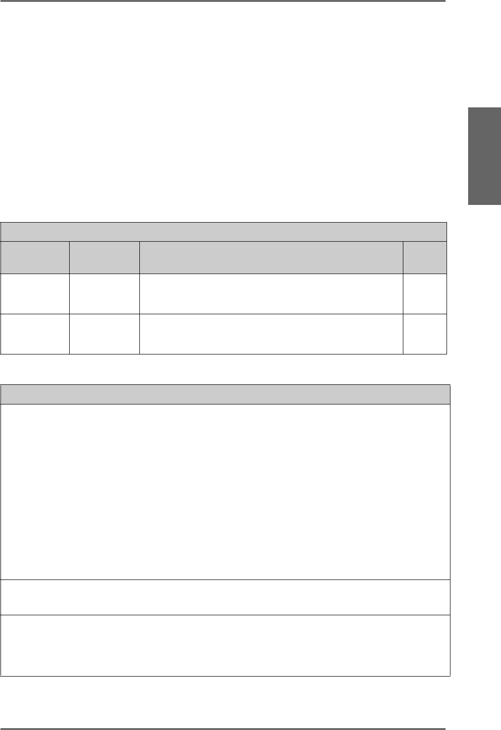
AVIATOR 700 system components
98-124743-F Appendix B: DO-160 specifications B-9
B.2.5 Configuration Module (CM) for SBU
T&T Part Number: 405040A-001
DO-160E string: Please refer to the section SwiftBroadband unit (SBU) on page B-7, as the
Configuration Module is an integral part of the SBU during normal operation and tests.
However, the section 25 Category A test is performed on the Configuration Module as an
individual LRU.
B.2.6 Tx Coupler and Rx Power Splitter
T&T Part Numbers: 405038A-002 and 405038A-003
DO-160D string: [(A1)(F1)X]CBB[SCL]EXXXXXZXXXZ[RR]M[A3E3]XXA
RTCA/DO-160D Change Numbers
Change
Number Date of Issue Title Section
Change No. 1 Dec. 14, 2000 Vibration
Radio Frequency Susceptibility
8.0
20.0
Change No. 2 June 12, 2001 Power Input
Audio Frequency Conducted Susceptibility - Power Inputs
16.0
18.0
Table B-6: RTCA/DO-160D Change Numbers, Tx Coupler and Rx Power Splitter
Conditions DO-160D Cat. Comments
Temperature and Altitude 4.0 A1 and
F1
Installation in controlled temperature locations
and inside or outside pressurized locations.
Low Temperature 4.5.1 Min. operating low temperature: -25°C
High Temperature 4.5.2 & 4.5.3 Max. operating high temperature: +55°C
In-Flight Loss of Cooling 4.5.4 X Forced cooling is not recommended.
Altitude 4.6.1 Max. altitude: 55000 ft
Decompression 4.6.2 Decompression at 55000 ft
Overpressure 4.6.3 Overpressure at -15000 ft
Temperature Variation 5.0 C Installation within controlled temperature
locations: 2°/min.
Humidity 6.0 B Severe humidity: 95% relative humidity at 38°C
to 65°C for 240 hours.
Installation within non-environmentally
controlled zones.
Table B-7: Environmental Qualification Form for Tx Coupler and Rx Power Splitter

AVIATOR 700 system components
B-10 Appendix B: DO-160 specifications 98-124743-F
Operational Shocks and
Crash Safety
7.0 B Equipment tested to: Standard operational
shocks and crash safety.
Vibration 8.0 SCL Standard sinusoidal and random vibration:
Aircraft type: Fixed wing. Turbojet, turbofan,
reciprocating or turbo propeller engines.
Aircraft zone: Fuselage
Explosion Proofness 9.0 E
Waterproofness 10.0 X No test required
Fluids Susceptibility 11.0 X No test required
Sand and Dust 12.0 X No test required
Fungus Resistance 13.0 X No test required
Salt Spray 14.0 X No test required
Magnetic Effect 15.0 Z Magnetic deflection distance: < 0.3 m
Power Input 16.0 X No test required
Voltage Spike 17.0 X No test required
Audio Frequency
Conducted Susceptibility -
Power Inputs
18.0 X No test required
Induced Signal
Susceptibility
19.0 Z Equipment intended for operation in systems
where interference-free operation is required
Radio Frequency
Susceptibility
20.0 RR High Intensity Radiated Field (HIRF) associated
with normal environment.
Emission of Radio
Frequency Energy
21.0 M
Lightning Induced Transient
Susceptibility
22.0 A3E3 Equipment and wiring in moderately exposed
environment in an all metal airframe.
Lightning Direct Effects 23.0 X No test required
Icing 24.0 X No test required
Electrostatic Discharge
(ESD)
25.0 A Operation, installation and repair in an
aerospace environment.
Conditions DO-160D Cat. Comments
Table B-7: Environmental Qualification Form for Tx Coupler and Rx Power Splitter (Continued)

AVIATOR 700 handsets and cradles
98-124743-F Appendix B: DO-160 specifications B-11
B.3 AVIATOR 700 handsets and cradles
B.3.1 4-Wire Handset and 4-Wire Cradle
T&T Part Number: 405620A-THW / 405620A-THR / 405622A-THW / 405622A-THR
DO-160C String: A1-BA[MNB]XXXXXXAXXXB[UR]ZXXE3XX
Note
For DO-160 specifications of the AVIATOR Wireless Handset see AVIATOR
Wireless Handset and Cradle Installation & Maintenance Manual (part number:
98-129600)
RTCA/DO-160C Change Numbers
Change
Number Date of Issue Title Section
Change No. 2 June 19, 1992 Lightning Induced Transient Susceptibility 22.0
Change No. 3 May 13, 1993 Radio Frequency Susceptibility 20.0
Table B-8: RTCA/DO-160C Change Numbers, 4-Wire Handset and Cradle
Conditions DO-160C Cat. Comments
Temperature and Altitude 4.0 A1 Installation in controlled temperature and
pressurized location.
Low Temperature 4.5.1 Min. operating low temperature: -25°C
High Temperature 4.5.2 & 4.5.3 Max. operating high temperature: +55°C
In-Flight Loss of Cooling 4.5.4 - No forced cooling required.
Altitude 4.6.1 Max. altitude: 55000 ft
Decompression 4.6.2 Decompression at 55000 ft
Overpressure 4.6.3 Overpressure at -15000 ft
Temperature Variation 5.0 B Installation within partially or non-controlled
temperature locations: 5°C/min.
Humidity 6.0 A Standard Humidity: 95% relative humidity at
38°C to 50°C for 48 hours.
Installation within environmentally
controlled zones
Operational Shocks and
Crash Safety
Operational Shock
Crash Safety
7.0
7.2
7.3
Yes
Yes
Yes
Equipment tested to: Standard operational
shocks and crash safety.
Table B-9: Environmental Qualification Form for 4-Wire Handset and Cradle

AVIATOR 700 handsets and cradles
B-12 Appendix B: DO-160 specifications 98-124743-F
Vibration 8.0 MB
N
Standard sinusoidal and random vibration:
Aircraft type: Fixed wing. Turbojet, turbofan,
reciprocating or turbo propeller engines.
Aircraft type: Helicopter. Turbojet or
reciprocating engines.
Aircraft zone: Instrument panel, console or
equipment rack.
Explosion Proofness 9.0 X No test required
Waterproofness 10.0 X No test required
Fluids Susceptibility 11.0 X No test required
Sand and Dust 12.0 X No test required
Fungus Resistance 13.0 X No test required
Salt Spray 14.0 X No test required
Magnetic Effect 15.0 A Magnetic deflection distance: 0.3 m to 1 m
Power Input 16.0 X No test required. DC power is provided by
the SDU.
Voltage Spike 17.0 X No test required
Audio Frequency Conducted
Susceptibility - Power Inputs
18.0 X No test required
Induced Signal Susceptibility 19.0 B Installation where interference is controlled
to a tolerable level.
Radio Frequency
Susceptibility
20.0 UR
Emission of Radio Frequency
Energy
21.0 Z Equipment intended for operation in
systems where interference-free operation
is required.
Lightning Induced Transient
Susceptibility
22.0 XXE3 Cable Bundle Test: Equipment and wiring in
moderately exposed environment in an all
metal airframe.
Lightning Direct Effects 23.0 X No test required
Icing 24.0 X No test required
Conditions DO-160C Cat. Comments
Table B-9: Environmental Qualification Form for 4-Wire Handset and Cradle (Continued)

AVIATOR 700 handsets and cradles
98-124743-F Appendix B: DO-160 specifications B-13
B.3.2 2-Wire Handset and 2-Wire Cradle
T&T Part Number: 405621B-THW / 405621B-THR / 405622B-THW / 405622B-THR
DO-160C String: [A1X]CAB[(SMB2)(SM)(UFF1)]XXXXXXAXXXB[RR]M[A2E3]XXA
Conditions DO-160D Cat. Comments
Temperature and Altitude 4.0 A1 Installation in controlled temperature and
pressurized location.
Low Temperature 4.5.1 Min. operating low temperature: -25°C
High Temperature 4.5.2 & 4.5.3 Max. operating high temperature: +55°C
In-Flight Loss of Cooling 4.5.4 X No forced cooling required.
Altitude 4.6.1 Max. altitude: 55000 ft
Decompression 4.6.2 Decompression at 55000 ft
Overpressure 4.6.3 Overpressure test at -15000 ft
Temperature Variation 5.0 C Installation within controlled temperature
locations: 2°/min.
Humidity 6.0 A Standard Humidity: 95% relative humidity at
38°C to 50°C for 48 hours.
Installation within environmentally
controlled zones.
Operational Shocks and Crash
Safety
7.0 B Equipment tested to: Standard operational
shocks and crash safety.
Vibration 8.0 S2B2
SM
UFF1
Standard random vibration:
Aircraft type: Fixed wing. Turbojet or
turbofan engines.
Standard sinusoidal vibration:
Aircraft type: Fixed wing. Reciprocating or
turbo propeller engines.
Robust Sine-on-Random vibration:
Aircraft type: Helicopter. Turbojet or
reciprocating engines.
Aircraft zone: Instrument panel, console or
equipment rack.
Explosion Proofness 9.0 X No test required
Waterproofness 10.0 X No test required
Table B-10: Environmental Qualification Form for 2-Wire Handset and Cradle

AVIATOR 700 handsets and cradles
B-14 Appendix B: DO-160 specifications 98-124743-F
Fluids Susceptibility 11.0 X No test required
Sand and Dust 12.0 X No test required
Fungus Resistance 13.0 X No test required
Salt Spray 14.0 X No test required
Magnetic Effect 15.0 A Magnetic deflection distance: 0.3 m to 1 m
Power Input 16.0 X No test required
Voltage Spike 17.0 X No test required
Audio Frequency Conducted
Susceptibility
18.0 X No test required
Induced Signal Susceptibility 19.0 B Installation where interference is controlled
to a tolerable level.
Radio Frequency Susceptibility 20.0 RR High Intensity Radiated Field (HIRF)
associated with normal environment.
Emission of Radio Frequency
Energy
21.0 M
Lightning induced Transient
Susceptibility
22.0 A2E3 Cable bundle test: Equipment and wiring in
moderately exposed environment in an all
metal airframe.
Lightning Direct Effects 23.0 X No test required
Icing 24.0 X No test required
Electrostatic Discharge (ESD) 25.0 A Operation, installation and repair in an
aerospace environment.
Conditions DO-160D Cat. Comments
Table B-10: Environmental Qualification Form for 2-Wire Handset and Cradle (Continued)
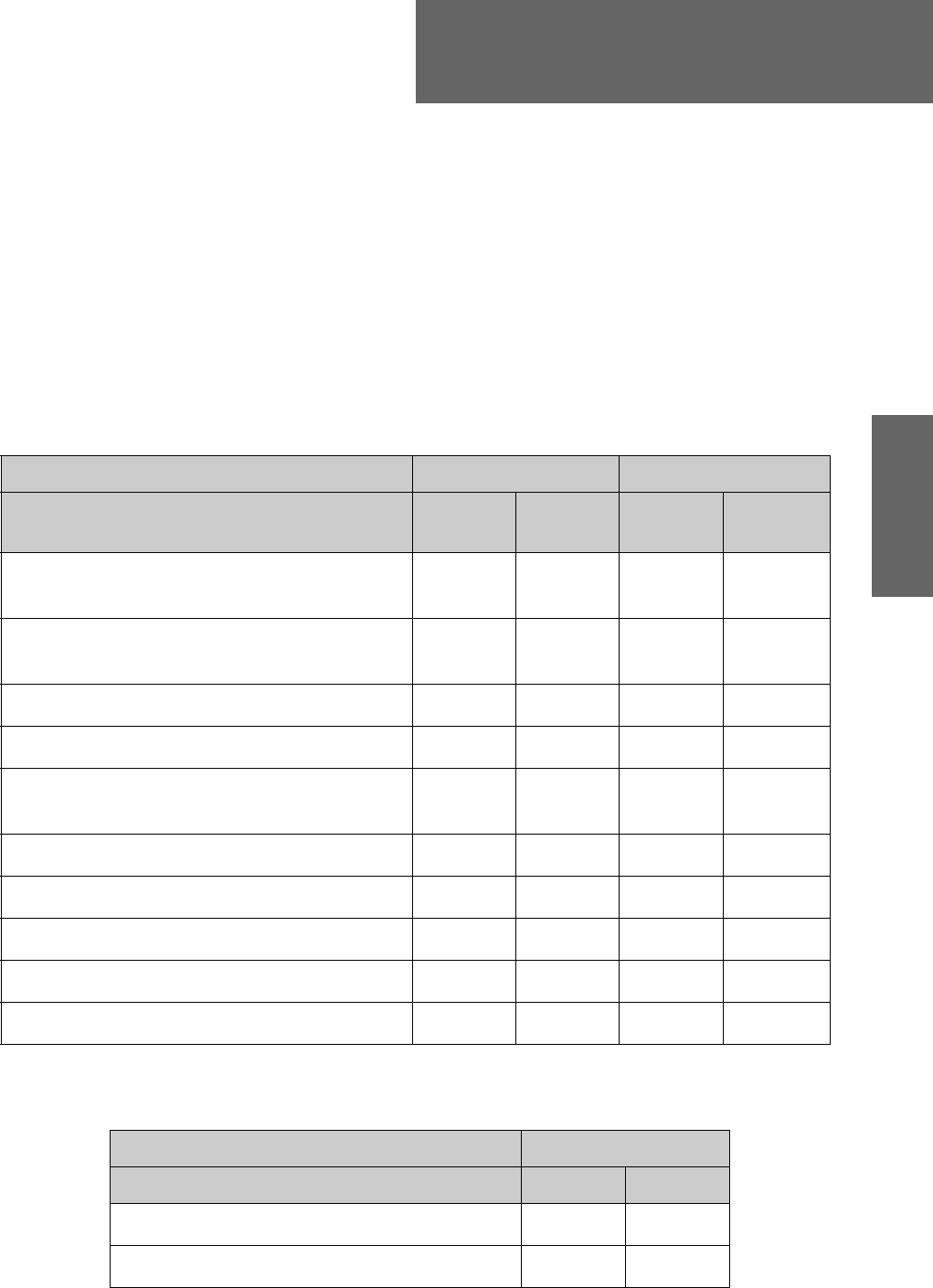
98-124743-F C-1
Appendix C
Upgrade from Aero-HSD+ to
AVIATOR 700 C
C.1 Avionics hardware needed
Depending on your current HSD+ Level E installation you need the following items to
upgrade your system to AVIATOR 700 (Level E) or AVIATOR 700D (Level D):
Table C-1: Items needed for upgrading to AVIATOR 700 Level E or AVIATOR 700D (Level D)
AVIATOR 700 (Level E) AVIATOR 700D (Level D)
Items needed for existing Aero-HSD+ system Aero-HSD+
4 channels
Aero-HSD+
5 channels
Aero-HSD+
4 channels
Aero-HSD+
5 channels
405040A SwiftBroadband Unit (SBU)
[without CM]
405040A-THD SwiftBroadband Unit (SBU)
[without CM]
Connector kit for TT-5040A
New tray for TT-5040A SBU
405040A-001 Configuration Module (CM) for
SBU
405040A-005 SDU to SBU Software Interface
405038A-002 TX-Coupler
405038A-003 RX Power Splitter
405035A-THD Satellite Data Unit (SDU) Level-D
405014A-THD High Power Amp (HPA) Level-D
Table C-2: Items needed for upgrading for different antenna types
Satcom antenna system
405013A DLNA Type F
405007A-801 Cobham BSU-7100
yes yes
yes yes
yes yes yes yes
yes yes yes yes
yes yes yes yes
yes yes yes yes
yes yes
yes yes
yes yes
yes yes
Item HGA-7000 Other
yes yes
yes no
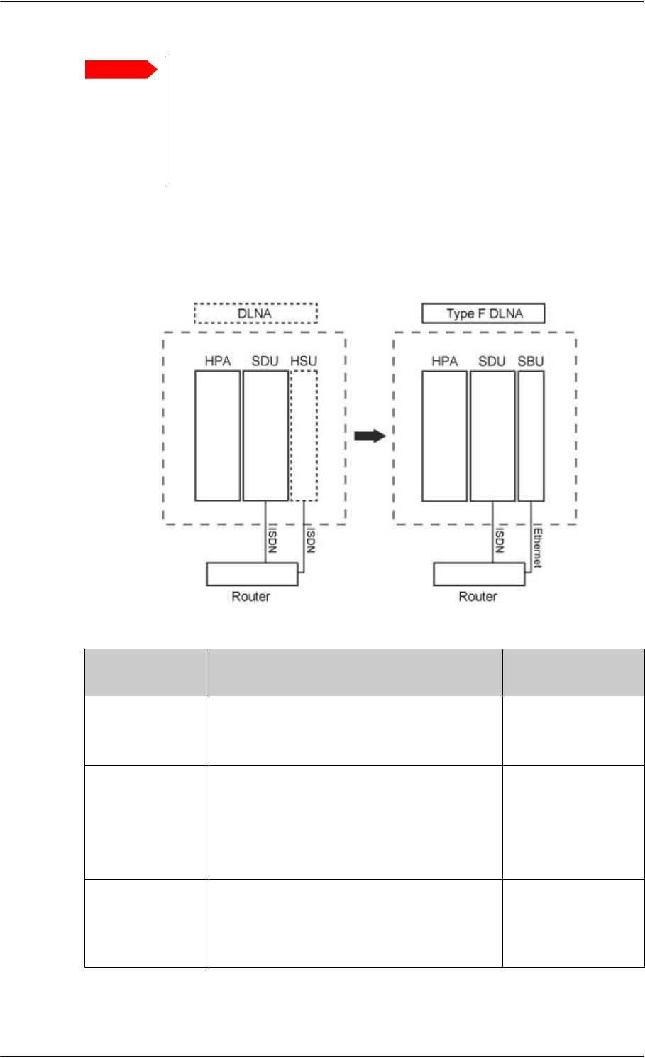
Level-D and Level E consistency!
When upgrading to a Level-D or Level-E certified system you must pay great
attention to secure consistency of the hardware units SDU, HPA and SBU —
all units and software must be either Level D or Level E.
A mismatch of Level D and Level E units or software is not allowed
and will result in a non-functioning system.
Mounting and wiring considerations
C-2 Appendix C: Upgrade from Aero-HSD+ to AVIATOR 700 98-124743-F
C.2 Mounting and wiring considerations
C.2.1 Overview
Important
Figure C-1: Upgrade overview, exchange HSU with SBU
Items to mount
and rewire Description More information
1. Tray for the
SBU The tray from an existing HSU can not be re-
used. The SBU requires a tray that is more
rigid.
3.12: SBU trays on
page 3-14
2. Connectors
HSU versus
SBU
The connector of an HSU only uses the top
plug.
The SBU also uses the bottom plug, and most
of the pins in the top plug have moved or
have new functions.
4.3.3: SBU rear
receptacle on
page 4-14
3. Aircraft power If the SBU is replacing an existing HSU, the
power wiring and circuit breaker may be re-
used, if it fulfills the slightly stricter
requirements.
5.3.3 Wiring power
supply: Wiring the
SwiftBroadband Unit
on page 5-15
Table C-3: Upgrade to AVIATOR 700, mounting and wiring considerations

Mounting and wiring considerations
98-124743-F Appendix C: Upgrade from Aero-HSD+ to AVIATOR 700 C-3
4. Satcom
antenna For an existing AMT-50/HGA-6000 antenna,
change only the diplexer to a Type F.
For an existing HGA-7000 antenna in
combination with a T&T 5012A Diplexer, the
following changes must be made:
• Change the diplexer to Type F, which is
physically slightly different.
• The Type F diplexer must be powered
directly from the aircraft power.
• The antenna, which was originally
powered through the T&T 5012A diplexer,
must now be powered through a Chelton
BSU-7100.
• Bring power wiring to the BSU.
• A429 wires must connect the BSU to the
HPA 5014A.
5. WLAN Optionally, mount the two WAN antennas and
connect them to the SBU.
5.2.7 WLAN
antennas on page 5-
8 and
5.3.9 Wiring WLAN
antenna interface
on page 5-43
6. User
interfaces If the user interfaces (ISDN, RS-232) of an
existing HSU is wired directly to the cabin, it is
recommended to wire some of the Ethernet
interfaces (i.e. Ethernet 1) from the SBU to
the cabin.
If the user interfaces (ISDN, RS-232) of an
existing HSU is wired to a Cabin Router, which
in turn provides the user connectivity, one of
the Ethernet interfaces of the SBU needs to
be wired to the Cabin Router.
If the system is a 4 channel, a new Ethernet
cable may be needed from the SBU to the
router. There should be two in total, one for
Ethernet WAN and one for ISDN fallback
(Swift64 on I3).
Also, route one or both of the 2-wire POTS
interfaces of the SBU to the cabin.
5.3.8 Wiring
Ethernet at the SBU
on page 5-40
Items to mount
and rewire Description More information
Table C-3: Upgrade to AVIATOR 700, mounting and wiring considerations (Continued)

Upgrading the SDU
C-4 Appendix C: Upgrade from Aero-HSD+ to AVIATOR 700 98-124743-F
C.2.2 Wiring navigational input IRS/AHRS
Even though the SDU has navigation data to feed to the SBU, the SBU also needs to
receiver position, track and speed information.
If IRS is used, the ARINC 429 signal must be wired to both the SDU and SBU.
If AHRS/GPS is used (with HGA-7000), only GPS L-band RF coax needs to be wired to both
the SDU and SBU. The cable to the SDU can be split with e.g. a 405038A-003 Power Splitter
(see TT-5038A-003 Rx Power Splitter on page 3-8).
Table C-4: Upgrade, wiring navigational input
Installation Existing SDU Additional SBU
Navigational input ARINC 429
input
GPS RF pin
TP A4
ARINC 429
input
GPS RF pin
BP A4
IRS
AHRS/GPS
For more information see 5.3.5, Wiring ARINC 429 interfaces on page 5-32.
C.3 Upgrading the SDU
The following steps are required to update the SDU to function properly in an AVIATOR
700 system:
1. SDU software update to version 1.14 or higher
2. Read the configuration from the SDU
3. Select the correct product: AVIATOR 700
4. Update the cable loss
5. Update the GES list with I-4 satellites
6. Update the known GES list
7. Write the configuration to the SDU
——
—
Note
Make sure you have the Aero-SDU Configuration Program v. 1.14 or higher.
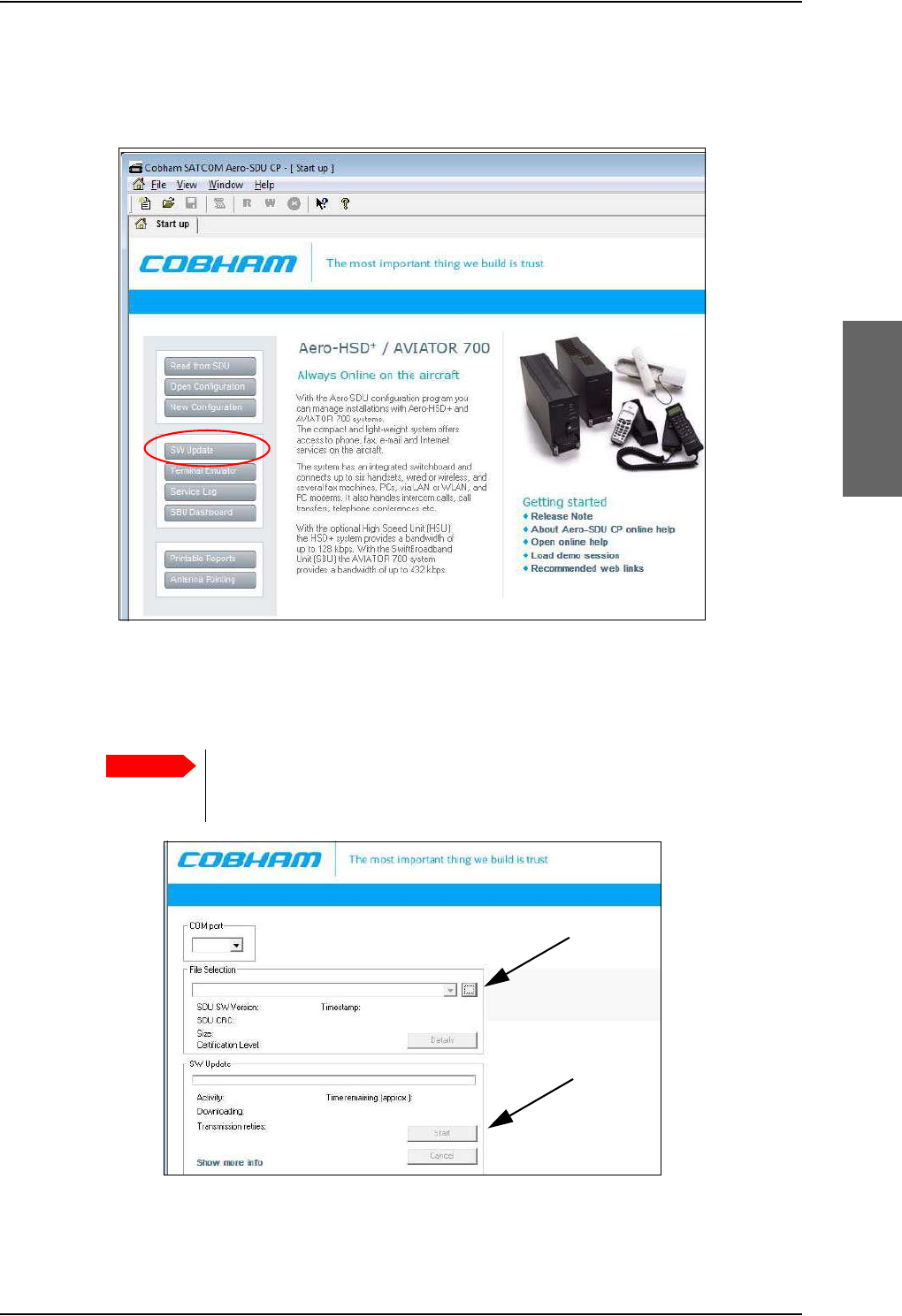
Upgrading the SDU
98-124743-F Appendix C: Upgrade from Aero-HSD+ to AVIATOR 700 C-5
C.3.1 SDU software update to version 1.14 or higher
1. Click the button SW Update to start the software update procedure.
Figure C-2: Upgrading HSD+ to AVIATOR 700, SDU, step 1/7
2. Download the software from www.cobham.com/satcom or for partners from
https://sync.cobham.com/satcom/support/downloads. Select the .SWU file and click the
button Start.
Pay great attention to selecting the correct software file: Level D or Level E for
both SDU and SBU. A mismatch of Level D and Level E software is not
allowed and will result in a non-functioning system.
Figure C-3: Upgrading HSD+ to AVIATOR 700, SDU, step 1/7, continued
Important
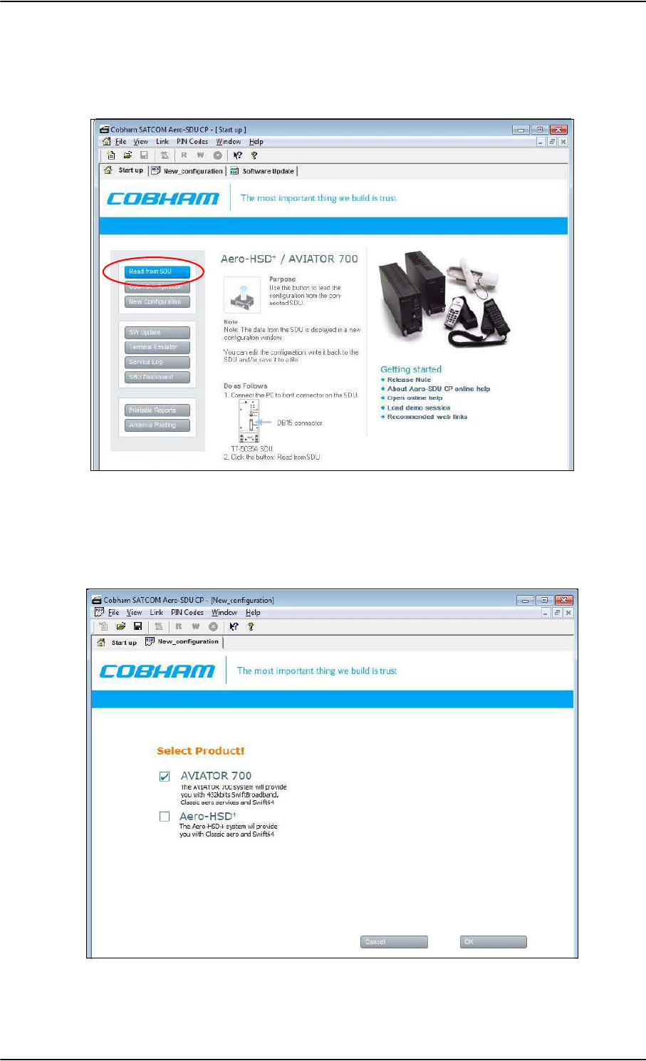
Upgrading the SDU
C-6 Appendix C: Upgrade from Aero-HSD+ to AVIATOR 700 98-124743-F
C.3.2 Read the configuration from the SDU
Click the button Read from SDU to read the current setting.
Figure C-4: Upgrading HSD+ to AVIATOR 700, SDU, step 2/7
C.3.3 Select the correct product: AVIATOR 700
Select the product AVIATOR 700 and click OK.
Figure C-5: Upgrading HSD+ to AVIATOR 700, SDU, step 3/7, continued
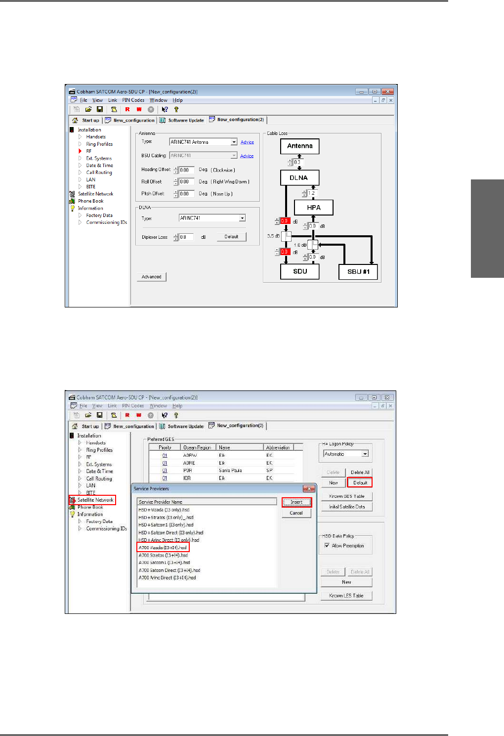
Upgrading the SDU
98-124743-F Appendix C: Upgrade from Aero-HSD+ to AVIATOR 700 C-7
C.3.4 Update the cable loss
Enter the values for the cable losses for the SDU on the page RF.
Figure C-6: Upgrading HSD+ to AVIATOR 700, SDU, step 4/7
C.3.5 Update the GES list with I-4 satellites
Add I-4 GESs on the page Satellite Network.
Figure C-7: Upgrading HSD+ to AVIATOR 700, SDU, step 5/7
12
3
4
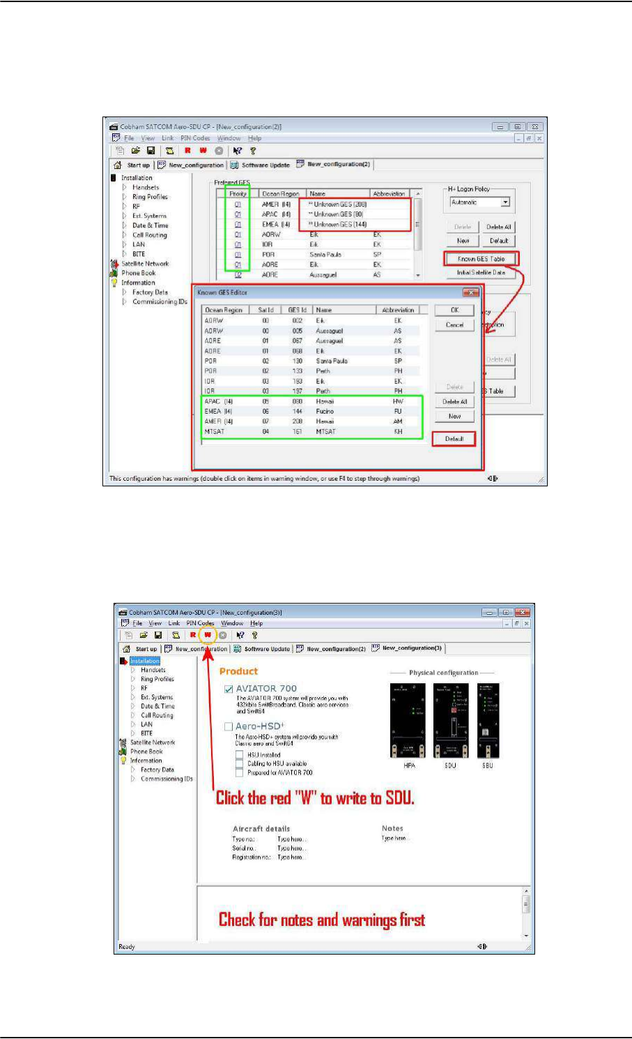
Upgrading the SDU
C-8 Appendix C: Upgrade from Aero-HSD+ to AVIATOR 700 98-124743-F
C.3.6 Update the known GES list
1. Update the Known GES Table on the page Satellite Network.
Figure C-8: Upgrading HSD+ to AVIATOR 700, SDU, step 6/7
C.3.7 Write the configuration to the SDU
Click the red button W to write the new configuration into the SDU.
Figure C-9: Upgrading HSD+ to AVIATOR 700, step 7/7

98-124743-F D-1
Appendix D
System messages D
D.1 Types of messages
The AVIATOR 700 system announces messages in the4-Wire Handset and the MCDU
display or in the built-in web interface of the SBU. In this appendix you find:
•H+ Cause Codes (information from I3 or I4 satellite)
•MPDS Cause Codes (from Swift64 coverage on I3)
•ISDN Cause Codes (SLCV, from Swift64 coverage on I3)
•List of BITE codes
•List of SBU events
Cause codes contain information from the satcom services or status information from the
system to the user.
BITE codes contain information from the AVIATOR 700 system. This information is a
result of a POST or PAST sequence or Continuous Monitoring performed by the Built-In
Test Equipment.

Cause Codes
D-2 Appendix D: System messages 98-124743-F
D.2 Cause Codes
D.2.1 H+ Cause Codes (information from I3 or I4 satellite)
Logon Reject Cause Codes
Display Text ID Description Guidance
ClassReject 0x88 Class rejected The GES does not support this class.
GlobChanLoss 0x82 Global channel loss Verify that there are no obstacles
between the satellite and the AES
antenna.
EMCON Active 0x8B Emission Control is active
GlobCunavlb 0x09 Global C channel not available at
GES
ManualLogRej 0x89 Manual login rejected Manual logon is not allowed when
logon policy is automatic.
NetworkFail 0x03 Network Failure
NoGesSignal 0x81 No GES signal
NoInitData 0x86 No valid system table available
NoSatSignal 0x80 No satellite signal Verify that there are no obstacles
between the satellite and the AES
antenna.
NotAuthorizd 0x0F AES not authorized Verify that the ICAO address used is
correct.
Verify that the ICAO address is
registered, by contacting the service
provider.
OtherReason 0x0E Other Reason
OutsideCover 0x84 Outside spot beam coverage The AES is not under a spot beam of
the specified GES.
P/R/Tunavlb 0x07 Packet data channel unavailable
PkdtaUnavlb 0x08 Packet data service unavailable
SatHandover 0x8C Satellite handover
SDUfailure 0x8A SDU failure Check the current BITE errors.
SpotChanLoss 0x83 Spot channel loss
TableFull 0x00 Table Full
Table D-1: List of H+ Logon Reject Cause Codes

Cause Codes
98-124743-F Appendix D: System messages D-3
Call Reject Cause Codes
The SLCV codes refer to: S = coding Standard, L = cause Location, C = cause Class, V = cause
Value.
UserLogoff 0x87 User logoff
VCC&dUnavlb 0x0A Voice not available at GES
VoiceUnavlb 0x01 Voice Unavailable
WrongGES 0x85 GES not existing Check GES ID validity.
WrongGESid 0x06 Wrong GES identifier Check GES ID validity.
WrongParam 0x02 Wrong Parameter
WrongSatID 0x05 Wrong Satellite identifier Check satellite ID validity.
Display Text ID Description Guidance
Table D-1: List of H+ Logon Reject Cause Codes (Continued)
Display text Code Description Guidance
S L C V
0 0 1 0 0 0 1 0 Normal clearing by called/calling
party
1 1 7 15 1 1 7 15 Undefined cause
1 2 7 15 1 2 7 15 Undefined cause
1 3 7 15 1 3 7 15 Undefined cause
1 4 7 15 1 4 7 15 Undefined cause
AddrComplete 1 3 0 1 Address complete signal sent to
terrestrial network
AddrComplete 1 6 0 1 Address complete signal received
from terrestrial network
AESabsent 1 3 7 3 Calling/called AES not logged-on
to system
AnalogFail 1 4 2 3 Analog data equipment not
supported at GES
AnalogRate 1 4 6 2 Analog data rate not supported
by GES
CallBarred 1 4 4 3 Called AES barred for incoming
calls
Table D-2: List of H+ Call Reject Cause Codes

Cause Codes
D-4 Appendix D: System messages 98-124743-F
CallPreempt 1 1 1 1 Preemption by higher priority call
at AES
The call is preempted, e.g.
because you attempted to
make an HSD call and HSD
is barred in the FLEX
configuration.
CardInvalid 1 3 6 1 Credit card type not supported
by GES
CardRejected 1 3 3 1 Credit card number rejected by
GES
DigitalFail 1 4 2 4 Digital data equipment not
supported at GES
DigitalRate 1 4 6 3 Digital data rate not supported
by GES
Handover 1 3 7 4 Spot beam handover
InvalidAddr 1 2 3 2 Call Ann. / C-ch. Assign. not recd.
from GES
InvalidAddr 1 3 3 2 Incomplete called (AES) number
InvalidAddr 1 4 3 2 Invalid called number format
received from AES
InvalidNumbr 0 4 1 12 Incomplete called number
format from AES
Network busy 1 2 5 1 C-channel continuity test failure
at AES/
Connect acknowledge not
received by AES
Network busy 1 3 5 1 C-Channel continuity test failure
at GES/AES not responding/
Incomplete call information
received from AES/
Interruption in received AES
carrier/
Connect acknowledge not
received by GES
NoAnswer 0 1 1 2 Expiry of answer time
supervision at AES
NoAnswer 0 4 1 2 Expiry of answer time
supervision at the MSSC
Display text Code Description Guidance
S L C V
Table D-2: List of H+ Call Reject Cause Codes (Continued)

Cause Codes
98-124743-F Appendix D: System messages D-5
NoChanAvail 1 3 2 1 C-channel frequency/power
unavailable at GES
NoUnitAvail 1 2 2 2 C-channel unit unavailable at AES
NoUnitAvail 1 3 2 2 C-channel unit unavailable at
GES
SatDestFail 1 1 4 1 Called AES terminal not in service
ServiceType 1 3 6 5 Service type not supported by
GES
SwitchBusy 0 2 2 10 GES equipment congestion
SwitchBusy 0 4 2 10 GES equipment congestion/
No route to destination from
GES/
Circuit to terrestrial network
unavailable
UnassignedNo 1 4 7 2 AES not authorized for service
Unauthorised 1 3 4 2 Calling AES not authorized for
service
UserBusy 1171 Called AES terminal busy
UserBusy 1 3 7 1 Call reference number
unavailable at GES
VoiceTypeErr 1264 Required voice channel
characteristics not supported by
AES
VoiceTypeErr 1364 Required voice channel
characteristics not supported by
GES
WrongNumber 0 4 0 1 Unallocated called number
received from AES
Display text Code Description Guidance
S L C V
Table D-2: List of H+ Call Reject Cause Codes (Continued)

Cause Codes
D-6 Appendix D: System messages 98-124743-F
D.2.2 MPDS Cause Codes (from Swift64 coverage on I3)
Layer 2 Reason Codes
L2 Reason
Number Interpretation
690 (2B2) Registration time-out
691 (2B3) Service connection establishment time-out
692 (2B4) Bearer time-out
693 (2B5) Preempted by master unit
700 Reason Unspecified
701 L3 Release
702 L3 Deregister
703 L3 Reject
716 SAN Idle Timer Expiry
717 MAN Idle Timer Expiry
718 SAN Connect Timer
719 SAN Modify Timer
720 SAN Handover Timer
721 SAN Connection Timer
722 MAN Connection Timer
732 Insufficient operating system resources at MAN
733 Insufficient memory at MAN
748 Invalid L3 Call Ref in Establish SDU
749 Invalid L3 Call Ref in Modify SDU
764 Unsupported IPDS MAC version
765 Invalid Bearer Connection type in Establish SDU
766 Invalid Bearer Control type in Establish SDU
767 Invalid Bearer Connection ID in Establish SDU
768 Invalid Bearer Connection type in Modify SDU
769 Invalid Bearer Control type in Modify SDU
770 Invalid Bearer Connection ID in Modify SDU
Table D-3: List of MPDS Layer 2 Reason Codes

Cause Codes
98-124743-F Appendix D: System messages D-7
771 Invalid Handover SDU
772 Invalid SDU type
773 SDU Incorrectly Formatted
780 Connection sub-layer protocol failure (MAN specific signalling)
781 Connection sub-layer protocol failure (HDLC signalling)
796 Control sub-layer protocol failure
812 Channel Unit failure
813 Hardware failure
814 MAN not responding to frequency corrections
815 MAN not responding to power corrections
816 MAN not responding to timing corrections
828 Internal SAN failure
829 SAN Shutting Down
844 Bearer Control - No satellite link
845 Bearer Control - No suitable contention slot
846 Bearer Control - Status Acknowledgement failure
847 Bearer Control - Incorrect SAN ID
860 No such MAN
861 Invalid L3 Call Reference
L2 Reason
Number Interpretation
Table D-3: List of MPDS Layer 2 Reason Codes (Continued)

Cause Codes
D-8 Appendix D: System messages 98-124743-F
D.2.3 ISDN Cause Codes (SLCV, from Swift64 coverage on I3)
The SLCV codes refer to: S = Coding Standard, L = cause Location, C = cause Class, V = cause
Value.
Code (Hex) Interpretation
S L C V
1 0 0 1 MES is clearing the call as instructed by the relevant MES terminal
equipment (i.e., normal clearing due to MES terminal “on-hook” etc.).
1 0 1 1 MES is rejecting the call because the specified MES terminal number is
currently busy, and MES has not been authorized to divert calls which are
addressed to that number.
1012MES is clearing the fixed-originated call because subsequent to the
acceptance of the call and the signalling of the identity of the mobile
terminal to which the call will actually be routed, that terminal has
become busy and cannot be called.
1021MES is clearing the call because appropriate “off-hook” signalling has not
been received from the addressed MES terminal (including any
authorized diversions) within the allowed time limit.
1081MES is rejecting the call because the specified MES terminal number has
not been installed, and MES has not been authorized to divert calls which
are addressed to that number.
1 0 9 1 MES is rejecting the call because the specified MES terminal number is
currently out-of-service, and MES has not been authorized to divert calls
which are addressed to that number.
1092MES is clearing the fixed-originated call because subsequent to the
acceptance of the call and the signalling of the identity of the mobile
terminal to which the call will actually be routed, that terminal has
become out-of-service and cannot be called.
1143MES is prematurely clearing the fixed-originated call which is in the
process of being established because the MES user has initiated a call
from a terminal which is authorized to automatically preempt an existing
fixed-originated call.
1144MES is prematurely clearing the MES-originated call which is in the
process of being established because the MES user has initiated a higher
priority call.
1145MES is prematurely clearing the mobile-originated call which is in the
process of being established because the MES user has initiated a call
from a terminal which is authorized to automatically preempt an existing
mobile-originated call.
Table D-4: List of ISDN Cause Codes (SLCV)

Cause Codes
98-124743-F Appendix D: System messages D-9
1 1 4 6 MES is prematurely clearing the mobile-originated call which is in the
process of being established because the MES user has abandoned the
call (by placing the originating terminal “on-hook”).
1 1 D 1 LES is rejecting the call because the “Service Nature” and/or “Service
Type” and/or “Channel parameter” information received from the MES is
invalid (e.g., not currently defined in the SDM, mutually contradictory, or
not applicable to a MES originated call).
1 1 D 2 LES is clearing the call because the “service address” information
received from the MES is invalid (i.e., less than 2 digits).
1 1 D 3 LES is clearing the call because the “service address” information
received from the MES is a 2-digit address which is either undefined or
which is currently unavailable at this LES.
1 1 D 5 LES is clearing the call because the “service address” information
received from the MES contains a country code which is regarded (by
this LES) as invalid.
1 1 D 6 LES is clearing the call because the “PID” information received from the
MES in the “scrambling vector” message (type 8D H) is not consistent
with the PID information in the Fixed/MES Originated (PID) and PID/MES
Registration Tables at the LES as it relates to this call.
1 2 0 2 (Spot Beam Handover): MES is ready to make the transition from the
current beam to the next beam.
1281MES is rejecting the call because the MES is not equipped to provide the
specified service.
1291MES is rejecting the call because although it is equipped to provide the
specified service, it is not currently able to do so.
1 2 B 1 MES is rejecting or clearing the call for a reason which is not covered by
any of the currently defined “Cause” events.
1 2 C 3 MES is clearing the call because a “LES Connect” message (type 8C H) has
not been received by the MES within the allowed time limit.
1 2 C 4 MES is clearing the call because the “authentication query” ISU message
(type B4 H) and/or the “authentication query” SSU message (type B5 H)
have not been received by the MES within the allowed time limit.
1 2 C 5 MES is clearing the call because an expected supplementary services
SU(s) has (have) not been received by the MES within the allowed time
limit.
Code (Hex) Interpretation
S L C V
Table D-4: List of ISDN Cause Codes (SLCV) (Continued)

Cause Codes
D-10 Appendix D: System messages 98-124743-F
1 2 C 6 MES is clearing the call because the “supplementary services
interrogation” ISU (type B2 H), and/or “subscriber digits” SSU (type AD H)
messages have not been received by the MES within the allowed time
limit.
1 2 C 7 MES is clearing the call because a “SCPC channel release” SU (type 8A H)
has not been received by the MES, in response to the transmission of a
“notification acknowledge” message (type BA H) during the
supplementary services call diversion information retrieval process,
within the allowed time limit.
1 2 C 8 (Spot Beam Handover): MES is clearing the call session in the next beam
because the MES did not detect the LESH carrier on the new frequency.
1 2 D 1 LES is rejecting the call because the “spot-beam ID” information received
from the MES is invalid (i.e., ID is not allocated on satellite in use).
1 2 D 2 LES is clearing the call because the “Scrambling Vector” information
received from the MES is invalid (i.e., 0000H, 6959H or 7FFFH).
1 3 6 2 MES is clearing the call because a long-term interruption in reception has
occurred (the definition of a “long-term interruption” depends upon the
service type, see Section B).
1 3 6 3 A Secondary Functional Centre of a Multi-channel MES is clearing the
call because the Primary Functional centre has commanded the Above-
decks equipment to re-point to a different Ocean Region.
Note: The above text is specific to a Fleet system. However, for the
AVIATOR 700 system this SLCV code is relevant when the H+ sub-system
is repointing the antenna from one ocean region to another. That will
cause the Swift64 sub-system to be pre-empted with the SLCV 1363.
1391MES is clearing the call because the call has lasted more than 700 km in
linear travelled distance.
1392MES is clearing the call because it has moved out of spot beam coverage.
1393MES in “cooperative mode” is clearing the call because of a pre-emption
request from the master entity.
1451LES is rejecting the call because an appropriate terrestrial circuit is not
currently available at this specific LES.
1452LES is rejecting the call because an appropriate channel unit and
associated terrestrial circuit are not currently available at this LES. [This
“cause” is only utilized when there is a permanent “one-to-one”
connection between appropriate channel units and their terrestrial
circuits].
Code (Hex) Interpretation
S L C V
Table D-4: List of ISDN Cause Codes (SLCV) (Continued)

Cause Codes
98-124743-F Appendix D: System messages D-11
1 5 0 2 (Spot Beam Handover): LES is ready to make the transition from the
current beam to the next beam and is clearing the call session in the
current beam (normal clear).
1551LES is rejecting the call because an appropriate satellite channel is not
currently available at this specific LES.
1581LES is rejecting the call because the requested service is not provided by
this specific LES.
1591LES is rejecting the call because the requested service is temporarily not
available at this specific LES.
1 5 A 1 LES is rejecting the call because the specified MES is not authorized for
any service at this specific LES.
1 5 A 2 LES is rejecting the call because the specified MES is not authorized to
use specific requested service via this specific LES.
1 5 A 3 LES is clearing the call because the “credit card data” information
received from the MES has been rejected by the credit card
authorization process.
1 5 A 4 LES is clearing the call because the data received from the MES in the
“authentication reply” message (type B6 H) has been declared “invalid”
by the LES authentication process.
1 5 A 5 LES is rejecting the call because the specified PID is not authorized for
any service at this specific LES.
1 5 A 6 LES is rejecting the call because the specified PID is not authorized to use
specific requested service via this specific LES.
1 5 A 7 LES is clearing the call because the service address received from the
MES is not authorized for the requested priority.
1 5 B 1 LES is rejecting or clearing the call for a reason which is not covered by
any of the currently defined “Cause” events.
1 5 C 1 LES is rejecting the call because an appropriate “Channel Assignment”
message has not been received by the LES within the allowed time limit.
1 5 C 2 LES is clearing the call because the “service address” information has not
been received by the LES within the allowed time limit.
1 5 C 3 LES is clearing the call because a “Scrambling Vector” message (type
8D H) has not been received by the LES within the allowed time limit.
1 5 C 4 LES is clearing the call because neither the “service address” information
nor a “Scrambling Vector” message (type 8D H) has been received by the
LES within the allowed time limit.
Code (Hex) Interpretation
S L C V
Table D-4: List of ISDN Cause Codes (SLCV) (Continued)

Cause Codes
D-12 Appendix D: System messages 98-124743-F
1 5 C 7 LES is clearing the call because a “MES Connect” message (type 99 H) has
not been received by the LES within the allowed time limit.
1 5 C 9 LES is clearing the call because a “authentication reply” message (type
B6 H) has not been received by the LES within the allowed time limit.
1 5 C A LES is clearing the call because a “notification acknowledge” message
(type BA H) has not been received by the LES within the allowed time
limit.
1 5 C B LES is clearing the call because the request sequence number contained
in the received “notification acknowledge” message (type BA) is not valid
(i.e. either not ‘0’ or not the next value in the sequence).
1 5 C C (Spot Beam Handover): LES is terminating the procedure because it did
not receive a response to the Handover Request from the NCS.
1 5 C D (Spot Beam Handover): LES is clearing the call session in the next beam
because the MES did not indicate that it was ready to make the transition
(possibly because the MES did not receive the Channel Assignment).
1 5 D 1 LES is rejecting the call because the “Channel Assignment” message
received from the NCS contains inappropriate or conflicting information.
1 5 D 2 LES is clearing this MES ID and channel number in the busy lists at LES
and NCS because a new call to/from this MES is being set-up (and thus
any previous call to/from this MES must have cleared).
1 5 E 1 LES is attempting to clear an MES which has sent an SCPC channel
release message but is found still to be transmitting 5.12 s later.
1651LES is rejecting the call because an appropriate channel unit is not
currently available at this specific LES.
1 6 6 1 LES is clearing the call because of an interruption in reception of the MES
carrier exceeding the allowed time limit.
1 6 C 2 LES is clearing the call because an appropriate SCPC MES carrier has not
been received by the LES (at the commencement of the call) within the
allowed time limit.
1 6 C 3 (Spot Beam Handover): LES is clearing the call session in the next beam
because the LES did not detect the MESH carrier on the new frequency.
1791LES is clearing the call because of a malfunction in the authentication
checking database or in the communications links thereto.
1811NCS is rejecting the call because the specified MES ID is in the “MES
busy” list at the NCS.
1812NCS is rejecting the call because the specified MES is busy with an IPDS
call at the NCS.
Code (Hex) Interpretation
S L C V
Table D-4: List of ISDN Cause Codes (SLCV) (Continued)

Cause Codes
98-124743-F Appendix D: System messages D-13
1813NCS is rejecting the call because the specified MES is busy with an IPDS
call at the NCS, and the call waiting notification was declined or timed
out by the MES.
1814NCS is rejecting the call because the specified MES is busy with an IPDS
call at the NCS, and call waiting notification is unavailable.
1851NCS is rejecting the call because an appropriate SCPC channel is not
currently available.
1852NCS is rejecting the call because no SCPC channel exists at the NCS
which matches the contents of the Channel Parameters, Service Nature,
Service Type, MES Category, Spot Beam ID and Priority fields contained
in the Request for Channel Assignment.
1853NCS is rejecting the call because no SCPC channel is currently available
for the specified lease marked MES.
1854NCS is rejecting the call because the MES is outside the spot beam
coverage area.
1855NCS is rejecting the call because an appropriate SCPC channel is not
currently available and channel pre-emption failed.
1 8 5 6 NCS is rejecting the call because the requested spot beam indicates
failed spot beam selection (“FF”) and an appropriate global SCPC channel
is not currently available.
1857(Spot Beam Handover) NCS is rejecting the Handover Request because
an appropriate SCPC channel is not available in the next beam.
1 8 A 1 NCS is rejecting the call because the specified MES ID was not found in
the “Forward and Return MES ID” cross-reference table.
1 8 A 2 NCS is rejecting the call because the specified MES is not authorized for
any service (except for Distress calls) at the NCS.
1 8 A 3 NCS is rejecting the call because the specified LES is not authorized for
the requested service at the NCS.
1 8 B 1 NCS is rejecting or clearing the call for a reason which is not covered by
any of the currently defined “Cause” events.
1 8 B 2 NCS is rejecting the call because the requested service variant is invalid.
1 8 C 1 NCS is rejecting the call because no message was received from the
specified MES (in reaction to a Call Announcement message) within the
allowed time limit.
1 8 C 3 NCS is rejecting the call because the specified MES was busy and the
MES pre-emption failed (i.e. no response within the allowed time limit).
Code (Hex) Interpretation
S L C V
Table D-4: List of ISDN Cause Codes (SLCV) (Continued)

Cause Codes
D-14 Appendix D: System messages 98-124743-F
1 8 D 1 NCS is rejecting the call because the Request for Call Announcement or
Request for Channel Assignment contains invalid or inappropriate
information.
1 8 E 1 NCS is rejecting the call because the specified MES ID is in the “MES
busy” list at the NCS, and is listed as being busy with a call through the
same LES as that now requesting a “call announcement” addressed to
that MES.
1 8 E 2 NCS is rejecting the call because the specified MES is busy with an IPDS
call through the same LES which is requesting the call announcement.
1 8 E 4 NCS is rejecting the call because the specified MES is busy with an IPDS
call through the same LES which is requesting the call announcement,
and the call waiting notification was declined or timed out by the MES.
1 8 E 5 NCS is rejecting the call because the specified MES is busy with an IPDS
call through the same LES which is requesting the call announcement,
and call waiting notification is unavailable.
1 F 0 1 LES is clearing the call because of the receipt of “on-hook” signalling from
the relevant terrestrial circuit (i.e., normal clearing).
1F11LES is clearing the call because the terrestrial called party is engaged
(busy).
1 F 2 1 LES is clearing the call because appropriate “off-hook” signalling from the
terrestrial called party has not been received by the LES within the
allowed time limit.
1 F 6 1 LES is clearing the call because of the detection of a failure in the
relevant terrestrial circuit.
1 F 6 2 The LES is clearing the call because the terrestrial calling party or the
terrestrial network has cleared the call before the “MES connect”
message has been received by the LES.
Code (Hex) Interpretation
S L C V
Table D-4: List of ISDN Cause Codes (SLCV) (Continued)

BITE Error codes
98-124743-F Appendix D: System messages D-15
D.3 BITE Error codes
D.3.1 Definition of severity levels
The 4-Wire Handset, the MCDU display and the SDU BITE display show Fatal and Essential
faults when possible.
Access to the full BITE log is only possible through the SDU Maintenance front connector.
The BITE log is included in the service log.
There are two BITE codes coming from the SBU. To see more details on errors and warnings
coming from the SBU you must use the built-in web interface of the SBU. It provides access
to the event list using the SBU Maintenance front connector.
Severity Definition
Fatal Total loss of service – Ongoing calls are
terminated and no further calls are allowed.
Essential Partial loss of service, action taken to isolate the
fault – some services / calls may work.
Non-E Non-Essential, no action taken, not displayed in
handset – only stored in BITE log.
Table D-5: Definition of severity levels for BITE codes

BITE Error codes
D-16 Appendix D: System messages 98-124743-F
D.3.2 List of BITE codes
Code LRU Severity Description Remedy
A501 HGA Fatal Fatal Antenna Failure (Cobham
HGA-7000)
Replace antenna
A502 HGA Essential Essential Antenna Failure
(Cobham HGA-7000)
Replace antenna
A503 HGA Non-E. Antenna Warning (Cobham
HGA-7000)
Check antenna error detail in slog.
Replace antenna
AA01 HGA Essential High Gain Antenna (Label 350
Bit 11)
Check antenna power and
communications lines, replace antenna
AAS1 S/HGA Essential STBO High Gain Antenna
(Label 350 Bit 11)
Check antenna power and
communications lines, replace STBD
antenna
AC01 ACU Essential Communication ACU/BSU-
HPA. No input from ACU/BSU
Check A429 lines between ACU/BSU and
HPA (BP13 & BP14). Replace ACU/BSU
AC02 ACU Essential Communication ACU/BSU-
HPA. invalid input from
ACU/BSU
Check A429 lines between ACU/BSU and
HPA, (BP13 & 14). Replace ACU/BSU
AC03 ACU Essential Any Internal Parameter (Label
350 Bit 18)
Replace ACU/BSU
AC04 ACU Non-E. Cross-talk Input Check A429 lines between Port & STBO
BSU
AC05 ACU Non-E. Control Bus Input (Label 350
Bit 13) BSU/ASU has no input
from HPA
Check Arinc 429 line from HPA to
ACU/BSU. HPA pins BP8 & BP9 and BP10
& BP11 in case of dual BSU installation
AC06 ACU Non-E. Internal RAM Replace ACU/BSU
AC07 ACU Non-E. Internal ROM Replace ACU/BSU
AC08 ACU Non-E. Internal Power Supply Replace ACU/BSU
AC09 ACU Non-E. Temperature Replace ACU/BSU
AC10 ACU Non-E. Parity Errors on ARINC429 Link Check A429 lines between ACU/BSU and
HPA, replace ACU/BSU
ACS1 S/ACU Essential Communication STBD
ACU/BSU-HPA. No input from
ACU/BSU (Dual PNL only)
Check A429 lines between STBD
ACU/BSU and HPA (BP15 & BP16).
Replace STBD ACU/BSU
Table D-6: List of BITE codes

BITE Error codes
98-124743-F Appendix D: System messages D-17
ACS2 S/ACU Essential Communication ACU/BSU-
HPA. Invalid input from
ACU/BSU
Check A429 lines between STBD
ACU/BSU and HPA (BP15 & BP16).
Replace STBD ACU/BSU
ACS3 S/ACU Essential Any Internal Parameter (Label
350 Bit 18)
Replace ACU/BSU
ACS4 S/ACU Non-E. Cross-talk Input Check A429 lines between Port & STBO
BSU
ACS5 S/ACU Non-E. Control Bus Input (Label 350
Bit 13) BSU/ASU has no input
from HPA
Check Arinc 429 line from HPA to
ACU/BSU. HPA pins BP10 & BP11
ACS6 S/ACU Non-E. Internal RAM Replace STBD ACU/BSU
ACS7 S/ACU Non-E. Internal ROM Replace STBD ACU/BSU
ACS8 S/ACU Non-E. Internal Power Supply Replace STBD ACU/BSU
ACS9 S/ACU Non-E. Temperature Replace STBD ACU/BSU
ACSA S/ACU Non-E. Parity Errors on ARINC429 Link Check A429 lines between STBD
ACU/BSU and HPA, replace STBD
ACU/BSU
AH01 HGA Essential BSU-HPA Port Dual Antenna
Cross installation
Check antenna coax lines, replace
antenna
AHS1 S/HGA Essential BSU-HPA STBD Dual Antenna
Cross installation
Check antenna coax lines, replace
antenna
AL01 LNA Essential LNA/Diplexer (Label 350 bit
20)
Check power and connections on DLNA,
replace DLNA
ALS1 S/LNA Essential STBD LNA/Diplexer (Label 350
bit 20)
Check power and connections on DLNA,
replace DLNA
AP01 HPR Essential High Power Relay Check wiring from BSU to HPR, replace
HPR
APS1 HPR Essential STBD High Power Relay Check wiring from BSU to HPR, replace
HPR
C502 Cable Essential SDU-DLNA RF RX Cable broken Check if HSU/SBU and SDU coaxes are
swapped or open on splitter, DLNA coax
is removed or open
C503 Cable Essential SDU-DLNA RF RX Cable
shorted
Check if DLNA and HSU/SBU coaxes are
swapped or shorted on splitter, DLNA
and SDU coaxes are swapped or shorted
Code LRU Severity Description Remedy
Table D-6: List of BITE codes (Continued)

BITE Error codes
D-18 Appendix D: System messages 98-124743-F
C601 Cable Fatal SDU - HPA Cable Test Check if TX coax between SDU and HPA
is open or shorted, Cables are swapped
on TX coupler
C705 Cable Fatal Communication Test with
HGA-7000 Antenna
Check if GPS, Modem, control coax open
or shorted between SDU and HGA-7000
antenna, Coax pigtails are swapped on
HGA-7000 antenna
C801 Cable Fatal Communication Test with HPA Check HPA power LED is green (if not,
check HPA nON signal between SDU
BP57 and HPA BP6 and power input)
Check RS-422 control lines SDU BP78/79
to HPA BP27/28 and SDU BP80/81 to
BP25/26. Replace HPA if persists
C802 Cable Fatal No GPS Signal to GPS Module Check GPS coax between antenna and
SDU, replace GPS antenna, replace SDU
C957 HPA Fatal HPA Communication with PSM
Module
Replace HPA
CA30 CM Fatal Invalid ICAO Number.
(Mismatch between CM and
strapping)
Check that ICAO strapping matches
ICAO programmed in configuration
module and that it is correct
CE01 SDU Fatal The H+ board certification
level is inconsistent
Replace SDU
CE02 SDU Essential The SDU unit certification level
is inconsistent
Replace SDU
CE03 HPA Fatal The HPA unit certification level
is inconsistent
Replace HPA
CE04 SDU Essential The HSD/HSU unit certification
level is inconsistent
Replace SDU
CE05 SBU Essential The SBU unit certification level
is inconsistent
Replace SBU
CE06 SDU,
HPA
Fatal The certification level between
SDU and HPA is inconsistent
Check and fix BITE C801. Check part
numbers for the SDU, SBU/HSU and HPA
all end in -THD (A700D) or all do NOT
end in -THD (HSD+ & A700 level-
E/legacy)
CE07 SDU Fatal The H+ boot code cannot find
the OTP cert. HW tag
Replace SDU
Code LRU Severity Description Remedy
Table D-6: List of BITE codes (Continued)

BITE Error codes
98-124743-F Appendix D: System messages D-19
CE08 System Essential The certification level between
H+, HSD or SBU is inconsistent
Check and fix BITE UU6S, Check part
numbers for the SDU, SBU/HSU and HPA
all end in -THD (A700D) or all do NOT
end in -THD (HSD+ & A700 level-
E/legacy)
CE09 SDU Essential The HSD boot code cannot
find the OTP cert. HW tag
Replace SDU
E108 CM Fatal Configuration Module Fitted
Test
Ensure that the proper Part number CM
is fitted in the SDU, reseat the CM, Make
sure SDU has latest SW, replace CM,
replace SDU
H201 HPA Fatal HPA Software Integrity Replace HPA
H202 HPA Fatal HPA Communication with
Main Module EEPROM
Replace HPA
H203 HPA Fatal HPA Essential Data Integrity If it happens after software upload, use
terminal emulator in SDU+CP, press
ctrl+x and select HPA shell, enter the
command "fixcrc" then reboot the
system to reset the HPA data table. If
BITE persists, replace HPA
H204 HPA Non-E. HPA Non-Essential Data
Integrity
Replace HPA
H401 HPA Fatal HPA Communication with
Main Module UART
Replace HPA
H502 HPA Fatal HPA Communication with
RFHP Module
Replace HPA
H701 HPA Fatal HPA FPGA Version Conflict Replace HPA
H803 HPA Fatal HPA Gain Adjustment Limit Fix any BITE C801/C601, Replace HPA
H804 HPA Fatal HPA Frequency Calibration Check TX coax SDU to coupler and
coupler to HPA
H805 HPA Fatal HPA 1st and 2nd Transistor fail Replace HPA
H901 HPA Fatal HPA Communication Failure HPA not receiving SDU RS-422 signal.
Check SDU BP78/79 to HPA BP27/28
HP01 HPA Fatal HPA Thermal Safe Operational
Limits
Check temperature around HPA, Replace
HPA
HP02 HPA Fatal RF power limit exceeded Replace HPA
Code LRU Severity Description Remedy
Table D-6: List of BITE codes (Continued)

BITE Error codes
D-20 Appendix D: System messages 98-124743-F
HP11 HPA Fatal ARINC 429 Interface Voltage
(-12 VD)
Replace HPA
HP13 HPA Fatal HPA Internal Voltage (+5V1A) Replace HPA
HP14 HPA Fatal ARINC 429 Interface Voltage
(+12 VD)
Replace HPA
HP15 HPA Fatal HPA HGA-7000 Supply Voltage
(+26 VA)
Replace HPA
HP17 HPA Fatal HPA RFHP Module Voltage
(+26 VC)
Replace HPA
HPF1 HPA Essential HPA Forced Cooling (FAN1,
FAN2 and FAN3)
Replace HPA
L101 DLNA Essential DLNA Current too high Replace DLNA
L102 DLNA Essential DLNA Current too low Replace DLNA
L201 DLNA Essential DLNA Gain Failure Replace DLNA
U402 SDU Fatal HPLUS Files Existing Test Replace SDU
U403 SDU Essential HPLUS Files CRC Test Replace SDU
U405 SDU Essential HPLUS Software Versions
Inconsistency Test
Replace SDU
U901 Cable Non-E. IRS/AHRS 1 Failure Check that IRS is aligned and ready,
Check A429 wires from IRS#1 to SDU
(BP 26 & BP27), check correct
configuration (Speed/Type), check all
labels valid
U902 Cable Non-E. IRS/AHRS 2 Failure Check that IRS is aligned and ready,
Check A429 wires from IRS#2 to SDU
(BP 28 & BP29), check correct
configuration (Speed/Type), check all
labels valid
U908 Cable Fatal IRS/AHRS/GPS Data Invalid Check and correct any
U901/U902/C802 BITEs.
U915 SDU Fatal SDU needs SW update to
support HPA
Update software in SDU
UA01 SDU Non-E. BITE Display Interface Data
Loop Test
Replace SDU
Code LRU Severity Description Remedy
Table D-6: List of BITE codes (Continued)

BITE Error codes
98-124743-F Appendix D: System messages D-21
UC00 SDU Essential 5.Lo Lock Detector Test Replace SDU
UC0G SDU Essential 5.Lo Lock Failure Replace SDU
UC0P SDU Essential Interface to C-FDM DSP
Channel 1 Test
Replace SDU
UC0Q SDU Essential Interface to TIF DSP Channel 1
Test
Replace SDU
UC10 SDU Essential 6.Lo Lock Detector Test Replace SDU
UC1G SDU Essential 6.Lo Lock Failure Replace SDU
UC1P SDU Essential Interface to C-FDM DSP
Channel 2 Test
Replace SDU
UC1Q SDU Essential Interface to TIF DSP Channel 2
Test
Replace SDU
UC1R SDU Essential SDU needs SW update (C-
Channel)
Try updating/reloading software in SDU
and HSU, replace SDU/HSU
UE01 SDU Non-E. HSD Rx Cable Test Replace SDU
UF01 SDU Fatal 1.Lo Lock Detector Test Replace SDU
UF02 SDU Fatal 2.Lo Lock Detector Test Replace SDU
UF03 SDU Fatal 3.Lo Lock Detector Test Replace SDU
UF04 SDU Fatal 4.Lo Lock Detector Test Replace SDU
UF30 SDU Fatal RT Channel ALC Test Replace SDU
UF51 SDU Essential 1.Lo Lock Failure Replace SDU
UF52 SDU Essential 2.Lo Lock Failure Replace SDU
UF53 SDU Essential 3.Lo Lock Failure Replace SDU
UF54 SDU Essential 4.Lo Lock Failure Replace SDU
UF71 SDU Fatal GPS Communication Test Replace SDU
UH01 SDU Essential 1.LO Low Lock Detector Test Replace SDU/HSU depending on location
in BITE list
UH02 SDU Essential 2.LO Low Lock Detector Test Replace SDU/HSU depending on location
in BITE list
Code LRU Severity Description Remedy
Table D-6: List of BITE codes (Continued)

BITE Error codes
D-22 Appendix D: System messages 98-124743-F
UH03 SDU Essential 3.LO Low Lock Detector Test Replace SDU/HSU depending on location
in BITE list
UH04 SDU Essential 1.LO High Lock Detector Test Replace SDU/HSU depending on location
in BITE list
UH05 SDU Essential 2.LO High Lock Detector Test Replace SDU/HSU depending on location
in BITE list
UH06 SDU Essential 3.LO High Lock Detector Test Replace SDU/HSU depending on location
in BITE list
UH11 SDU Essential 1.LO Minimum Frequency Test Replace SDU/HSU depending on location
in BITE list
UH12 SDU Essential 2.LO Minimum Frequency Test Replace SDU/HSU depending on location
in BITE list
UH13 SDU Essential 3.LO Minimum Frequency Test Replace SDU/HSU depending on location
in BITE list
UH18 SDU Essential 1.LO Lock Time Test Replace SDU/HSU depending on location
in BITE list
UH19 SDU Essential 2.LO Lock Time Test Replace SDU/HSU depending on location
in BITE list
UH20 SDU Essential 3.LO Lock Time Test Replace SDU/HSU depending on location
in BITE list
UH21 SDU Essential 1.LO Maximum Frequency Test Replace SDU/HSU depending on location
in BITE list
UH22 SDU Essential 2.LO Maximum Frequency Test Replace SDU/HSU depending on location
in BITE list
UH23 SDU Essential 3.LO Maximum Frequency Test Replace SDU/HSU depending on location
in BITE list
UH24 SDU Essential 1.LO DDS Divider Test SDU is not able to see the satellite. Bad
PRT signal and the master oscillator is
not able to tune. Normally shown with
UH25,UH32 and UH3B. Check for ACU
fault. Check coaxes in the RX path, make
sure DLNA on/off is wired correctly,
replace DLNA, replace SDU
Code LRU Severity Description Remedy
Table D-6: List of BITE codes (Continued)

BITE Error codes
98-124743-F Appendix D: System messages D-23
UH25 SDU Essential 3.LO DDS Divider Test SDU is not able to see the satellite. Bad
PRT signal and the master oscillator is
not able to tune. Normally shown with
UH24,UH32 and UH3B. Check for ACU
fault. Check coaxes in the RX path, make
sure DLNA on/off is wired correctly,
replace DLNA, replace SDU
UH30 SDU Essential ALC Carrier off Test Replace SDU/HSU depending on location
in BITE list
UH31 SDU Essential ALC Carrier on Test Replace SDU/HSU depending on location
in BITE list
UH32 SDU Essential RF BER Loop Back Test SDU is not able to see the satellite. Bad
PRT signal and the master oscillator is
not able to tune. Normally shown with
UH24, UH25 and UH3D. Check for ACU
fault. Check coaxes in the RX path, make
sure DLNA on/off is wired correctly,
replace DLNA, replace SDU
UH33 SDU Non-E. Average Amplitude Test Replace SDU/HSU depending on location
in BITE list
UH35 SDU Non-E. Step Attenuator Test Replace SDU/HSU depending on location
in BITE list
UH3B SDU Essential Rx TX frequency offset to big
Test
SDU is not able to see the satellite. Bad
PRT signal and the master oscillator is
not able to tune. Normally shown with
UH24, UH25 and UH32. Check for ACU
fault. Check coaxes in the RX path, make
sure DLNA on/off is wired correctly,
replace DLNA, replace SDU
UH3D SDU Essential Loop Back Switch Test Replace SDU/HSU depending on location
in BITE list
UH51 SDU Essential 1.LO Lock Failure Replace SDU/HSU depending on location
in BITE list
UH52 SDU Essential 2.LO Lock Failure Replace SDU/HSU depending on location
in BITE list
UH53 SDU Essential 3.LO Lock Failure Replace SDU/HSU depending on location
in BITE list
UH61 SDU Essential ALC Level to Low Test Replace SDU/HSU depending on location
in BITE list
Code LRU Severity Description Remedy
Table D-6: List of BITE codes (Continued)

BITE Error codes
D-24 Appendix D: System messages 98-124743-F
UH62 SDU Essential ALC Level to High Test Replace SDU/HSU depending on location
in BITE list
UH63 SDU Essential Master Oscillator to low Replace SDU/HSU depending on location
in BITE list
UH64 SDU Essential Master Oscillator to high Replace SDU/HSU depending on location
in BITE list
UH70 SDU Essential Communication problem with
H+ system
Replace SDU
UH78 SDU Essential Position Unavailable In HGR and/or IRS/AHRS not aligned
UH79 SDU Essential Velocity Unavailable In HGR and/or IRS/AHRS not aligned
UH7D SDU Non-E. Software Versions Consistency
Test
Reload SDU software. Replace SDU is
BITE persists.
UH7F SDU Non-E. ATE pins connected. Not
allowed
Ensure ATE pins are not shorted (should
not be pinned)
UH7G SDU Non-E. ATE pins connected. Not
allowed
Ensure ATE pins are not shorted (should
not be pinned)
UH82 SDU Essential Parameter Block Checksum
Test HSD
Replace SDU/HSU depending on location
in BITE list
UH83 SDU Essential CPU Application CRC Test Replace SDU/HSU depending on location
in BITE list
UH84 SDU Essential CPU RAM Test Replace SDU/HSU depending on location
in BITE list
UH85 SDU Non-E. Battery Check Test HSD Replace SDU/HSU depending on location
in BITE list
UH87 SDU Essential All Files Exist in Flash Test Replace SDU/HSU depending on location
in BITE list
UH88 SDU Essential Flash Files CRC Test Replace SDU/HSU depending on location
in BITE list
UH89 SDU Essential SDU needs SW update (HSD) Try updating/reloading software in SDU,
replace SDU
UH91 SDU Non-E. DSP Debug Port Test Replace SDU/HSU depending on location
in BITE list
UH95 SDU Essential Frame DSP Interface Test Replace SDU/HSU depending on location
in BITE list
Code LRU Severity Description Remedy
Table D-6: List of BITE codes (Continued)

BITE Error codes
98-124743-F Appendix D: System messages D-25
UH96 SDU Essential Turbo FPGA Interface Failure Replace SDU/HSU depending on location
in BITE list
UH97 SDU Essential Frame DSP to VFC DSP
interface
Replace SDU/HSU depending on location
in BITE list
UH98 SDU Essential VFC DSP Interface Test Replace SDU/HSU depending on location
in BITE list
UHA1 SDU Non-E. Burst Duration Monitor Circuit
Test
Replace SDU/HSU depending on location
in BITE list
UHA4 SDU Essential TDM Burst Duration Test Replace SDU/HSU depending on location
in BITE list
UHA5 SDU Essential Carrier On Signals Test Replace SDU/HSU depending on location
in BITE list
UHA6 SDU Essential Turbo FPGA Load Test Replace SDU/HSU depending on location
in BITE list
UHA7 SDU Essential ISDN Transceiver Interface
Test
Replace SDU/HSU depending on location
in BITE list
UHA8 SDU Essential ISDN Supply Voltage Test Replace SDU/HSU depending on location
in BITE list
UHA9 SDU Essential ISDN Rx Voltage Test Replace SDU/HSU depending on location
in BITE list
UHAA SDU Essential Turbo FPGA RAM Test Replace SDU/HSU depending on location
in BITE list
UHAB SDU Essential Power Fail sensor false alarm Replace SDU/HSU depending on location
in BITE list
UHAC SDU Essential ISDN 38 V shorted. The current limit on the 38V power
output has been exceeded and the
output power has therefore been turned
off. Remove the device(s) connected and
restart the system, check for proper pin
out and shorted ISDN wires
UHB0 SDU Non-E. Environment temperature to
low
Replace SDU/HSU depending on location
in BITE list
UHB1 SDU Non-E. Temperature Sensor Test Replace SDU/HSU depending on location
in BITE list
UHEE SDU Essential EEPROM Essential Data Test Replace SDU/HSU depending on location
in BITE list
Code LRU Severity Description Remedy
Table D-6: List of BITE codes (Continued)

BITE Error codes
D-26 Appendix D: System messages 98-124743-F
UHEU SDU Non-E. EEPROM Test Replace SDU/HSU depending on location
in BITE list
UHP0 SDU Essential Communication Test with
HSD-CPU
Replace SDU/HSU depending on location
in BITE list
UHW2 SDU Non-E. Master Oscillator needs
calibration
Replace SDU/HSU depending on location
in BITE list
UU02 SDU Essential Parameter Block Checksum
Test
With aircraft outside and nave system
up, from terminal emulator enter the
command "TX -x -1" and hit enter. The
system will reboot and parameter block
will be reset.
UU10 SDU Essential PRT DSP Interface Test Replace the SDU
UU16 SDU Essential UART Loop Back, CPDF
(COM12) Test
Replace the SDU
UU19 SDU Essential SDU needs SW update (H+) Replace the SDU
UU1C SDU Non-E. Temperature Sensor Test Replace the SDU
UU1D SDU Fatal Environment Temperature
Failure, H-Plus
Replace the SDU
UU20 SDU Non-E. H+ EEPROM Non Essential Data
Test
Replace the SDU
UU21 SDU Fatal H+ EEPROM Essential Data Test Replace the SDU
UU23 SDU Essential H+/HSD SW Version
Inconsistency Test
Make sure SDU & HSU has latest
software, replace SDU, replace HSU
UU24 SBU Essential H+/SBU SW Version
Inconsistency Test
Make sure SDU & SBU has latest
software, replace SDU, replace SBU
UU60 SDU Essential PBX DSP Interface Test Replace the SDU
UU6H SDU Essential Communication Problem with
HSD CPU, H+ Detected
Check "location" of BITE with SDU+CP
Terminal Emulator "list" or in handset. If
location [HSD pcb] reload software in
SDU and replace SDU if BITE persists
after reboot. If location [HSU pcb] check
Arinc 429 connection to HSU (SDU
BP32/33 to HSU TP19/20 and SDU
BP34/35 to HSU TP21/22), check HSU
power and software version. Replace
HSU if persist after reboot
Code LRU Severity Description Remedy
Table D-6: List of BITE codes (Continued)
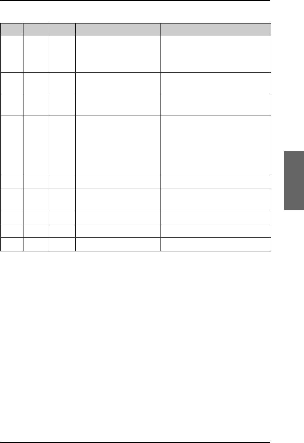
BITE Error codes
98-124743-F Appendix D: System messages D-27
UU6K Cable Essential Calibration problem with HSU
TX cable
HSU TX coax on TX coupler is
disconnected or broken or the SDU and
HPA connectors are swapped on the TX
coupler
UU6L SBU Essential Essential error in SBU See SBU dashboard/event list for further
troubleshooting of the SBU
UU6M SBU Non-E. Non-essential error in SBU See SBU dashboard/event list for further
troubleshooting of the SBU
UU6S SBU Essential Communication Problem with
H+/SBU CPU, H+ Detected
Ensure SBU power LED is Green (if
Amber, check SBU enable discrete (SDU
BP56 to SBU TP8)), check SBU "SYSTEM
TYPE" is configured as AVIATOR 700,
check RS-422 lines between SDU
BP73/72 to SBU TP20/19 and SDU
BP71/70 to SBU TP22/21
UUB1 SDU Non-E. Battery Check Test Replace the SDU
UUC0 CM Fatal System Configuration Test Ensure SDU configuration is written to
CM
UUC1 CM Essential CM CRC Error Replace CM
UUC2 CM Essential Config Module Needs Upgrade Replace CM
UUCU CM Fatal Configuration Module Test Replace CM
Code LRU Severity Description Remedy
Table D-6: List of BITE codes (Continued)

List of SBU events
D-28 Appendix D: System messages 98-124743-F
D.4 List of SBU events
The following list explains the events (warnings and errors) that may show in the web
interface of the SBU.
Event
ID ID range Severity Description Explanation Remedy
0100 00100 to
00199
ERROR System data
damaged
Important system data is
damaged
Do not use the terminal.
Contact your Cobham SATCOM
partner.
0210 00210 to
00219
ERROR SIM module
error
The SIM interface on the
terminal cannot be used.
Contact your Cobham SATCOM
partner.
0240 00240 to
00249
ERROR Temperature
sensor error
The terminal is in danger of
overheating.
Do not use the terminal.
Contact your Cobham SATCOM
partner.
0260 00260 to
00269
ERROR System error The terminal cannot
communicate on the
satellite network.
Contact your Cobham SATCOM
partner.
0300 00300 to
00309
ERROR GPS module
error
The GPS module is out of
function. The terminal
cannot obtain a valid GPS
position.
Contact your Cobham SATCOM
partner.
0310 0310 ERROR WLAN module
error
The WLAN access point
failed initialization
Contact your Cobham SATCOM
partner if the problem persists.
0330 00330 to
00339
ERROR ISDN failure The ISDN interface on the
terminal cannot be used.
Contact your Cobham SATCOM
partner.
0340 00340 to
00349
ERROR 2-wire failure The Phone/Fax interface of
the terminal cannot be used.
Contact your Cobham SATCOM
partner.
0350 00350 to
00359
ERROR AD9864
calibration data
error
Internal error in the
receiving part of the
terminal.
Contact your Cobham SATCOM
partner if the problem persists.
0380 0380 ERROR SNMP agent
initialization
failed
The SNMP agent failed
initialization
Contact your Cobham SATCOM
partner if the problem persists.
1010 01010 to
01019
WARNING Temperature
too low
(critical)
Low ambient temperature is
causing the performance of
the terminal to be degraded
or halted.
Move the terminal to a warmer
location. For information on
ambient temperature limits, see
the installation manual.
Table D-7: SBU events

List of SBU events
98-124743-F Appendix D: System messages D-29
1020 01020 to
01029
WARNING Too low
temperature
warning
Low ambient temperature is
causing the performance of
the terminal to be degraded
or halted. The terminal will
assume radio silence if the
problem is in the HLD.
Move the terminal to a warmer
location. For information on
ambient temperature limits, see
the installation manual.
1110 01110 to
01119
WARNING Temperature
too high
(critical)
Terminal: Critically high
temperature is causing the
terminal to shut down.
HLD: Critically high
temperature is causing the
HLD to stop transmission.
If possible, move the failing unit
to a cooler location. For
information on ambient
temperature limits, see the
installation manual. Contact
your Cobham SATCOM partner
if the problem persists.
1120 01120 to
01129
WARNING Too high
temperature
warning
High ambient temperature is
causing the performance of
the terminal to be degraded
or halted.
If the problem is in the
terminal: All PoE ports are
shut down, except port 1
and the bit rate for Standard
data is reduced. If the
problem is in the HLD: The
bit rate is reduced.
Move the terminal to a cooler
location. For information on
ambient temperature limits, see
the installation manual.
1400 01400 to
01409
WARNING Satellite signal
lost
The AVIATOR system no
longer receives a signal from
the satellite.
Make sure the antenna has a
free line of sight to the satellite.
Check the Rx cables W2
between the SBU and the HLD
and W3 between the satcom
antenna and the HLD.
1600 01600 to
01609
WARNING SOS call only The SIM card is not
accepted by the network.
Only emergency calls are
allowed.
Enter the PIN and wait for
network approval. If the
problem persists, contact your
Airtime Provider.
1700 01700 to
01709
WARNING Registration for
voice failed
The AVIATOR system has
not yet been allowed to
register for voice services
(Circuit Switched).
Your SIM card may be
blocked by the service
provider.
Contact your service provider if
the problem persists.
Event
ID ID range Severity Description Explanation Remedy
Table D-7: SBU events (Continued)

List of SBU events
D-30 Appendix D: System messages 98-124743-F
1800 01800 to
01809
WARNING Registration for
data failed
The AVIATOR system has
not yet been allowed to
register for data services
(Packet Switched).
Your SIM card may be
blocked by the service
provider.
Contact your service provider if
the problem persists.
2900 02900 to
02909
WARNING Network failed
authentication
The AVIATOR system does
not accept the network as a
valid BGAN network.
Restart the AVIATOR system.
Contact your Cobham SATCOM
partner if the problem persists.
3500 3500 ERROR 2-wire
calibration
failure
2-wire calibration failed on
the Phone/Fax interface,
because of: Common mode
balance error. The phone is
off hook. Wires are shorted
to each other or shorted to
ground.
Check the wires to your phone
or fax. Put the phone on hook.
Check the wires.
3600 03600 to
03609
ERROR 2-wire
operational
failure
The Phone/Fax interface
fails to operate, for one of
the following reasons:
Ground shorted. Power
overload. Temperature
overload.
Check the wires. Wait until the
event is cleared; then try again.
Wait until the event is cleared;
then try again.
3900 3900 ERROR Air link error Problems related to TX and
Rx DSPs. Example: PLL out of
lock.
Contact your Cobham SATCOM
partner
801F 801F WARNING Power Hold-up
- the input
voltage has
dropped
A power glitch was detected,
the length of the glitch
exceeds what the power
supply can absorb. This
event could have negative
influence on ongoing
connections.
Check external power
connection.
8020 8020 ERROR Power Hold-up
- the terminal
has lost power
for more than
200 ms
The terminal has lost power
for more than 200 ms.
Check the external power
connection.
8040 8040 WARNING Excessive
writes to the
flash memory
Wrong APN name or user
name/ password for a
connection which is set to
auto-activate.
Check that the APN name, user
name and password are set up
correctly for your connections.
Event
ID ID range Severity Description Explanation Remedy
Table D-7: SBU events (Continued)

List of SBU events
98-124743-F Appendix D: System messages D-31
8041 8041 ERROR Flex key is
missing or
corrupt
The license system has
detected a corrupt or
missing Flex Key.
Re-install your Flex key. Please
find your Flex key on the
Certificate of Conformity (CoC)
of the TT-5040A-001
Configuration Module.
8042 8042 ERROR Can not read
from
Configuration
Module
This error occurs when the
TT-5040A-001
Configuration Module has
not been inserted into the
back of the TT-5040A SBU.
Insert the TT-5040A-001
Configuration Module into the
back of the TT-5040A SBU.
8043 8043 ERROR Flash on
Configuration
Module corrupt
The AVIATOR system has
detected corrupt data on the
TT-5040A-001
Configuration Module.
Please contact your Cobham
SATCOM partner for further
assistance.
8044 8044 ERROR Flash on
Configuration
Module is
getting worn
out
The Configuration Module is
aging and will have less that
10% of the expected lifetime
left.
The Configuration Module still
works but has to be replaceable
in a timely manner
804A 804A WARNING Flash on
Configuration
Module is worn
out
The Configuration Module is
completely worn-out and
will have to be replaced.
The Configuration Module
might still be operational but
can fail at any time since the
expected lifetime has been
exceeded.
804C 804C WARNING The chosen
satellite is not
visible at
current GPS
position
The terminal is set up to use
a satellite that is not visible
at the current GNSS position.
Enter the web interface and
select SETTINGS > Satellite
selection. Then select Auto to
let the terminal automatically
find the satellite with the best
signal, or select a satellite visible
from your current position.
804F 804F WARNING ARINC-429
Navigational
input is missing
or not yet
ready
None of the navigational
inputs receive valid data for
one of the following reasons:
Wiring is broken. The
navigational source is not
switched on or power-on
sequence takes longer time
than expected.
Check the wiring. Wait until
power-on sequence has
completed for the external
navigational data source. Check
if the external unit has been
configured properly.
Event
ID ID range Severity Description Explanation Remedy
Table D-7: SBU events (Continued)

List of SBU events
D-32 Appendix D: System messages 98-124743-F
8053 8053 ERROR SDU
Communica-
tion error
The communication
between the SBU (TT5040A)
and SDU (TT5035A is not
working. This error applies to
AVIATOR 700 systems only.
Check that the RS-422
connection between SBU and
SDU is made correct. Check that
the SDU has the correct SW and
power up. Check that the SDU is
configured to an AVIATOR 700
system.
8054 8054 WARNING Transmission
aborted due to
extreme
temperature
The system stops all
transmission because the
temperature is critically high
or critically low.
None. The system must operate
within the allowed temperature
range to work properly. For
information on ambient
temperature limits, see the
installation manual.
8056 08056 WARNING USIM rejected The type of USIM card
inserted in the terminal is
not correct for your
terminal.
Make sure you have the correct
type of USIM card.
8060 8060 WARNING NAT session
table full
There are too many open
connections through NAT -
typically too many users
generating too much web
traffic.
Do not establish new
connections until the load has
been reduced.
8075 08075 ERROR DO-178B or
DO-254
certification
level is
inconsistent
The system consists of
mixed Level-E and Level-D
units.
The system is not operational.
Contact your Cobham SATCOM
partner.
8077 8077 WARNING Multi-voice
control
connection
config failure
Data write procedure failed
when making a connection.
Reboot the SBU or make a reset
to factory default settings. If
this does not help contact your
Cobham SATCOM partner.
8079 8079 WARNING Multi-voice
control
connection
error
Not possible to establish
connection to Multi-voice
server.
Check that Multi-voice is
included in your airtime
subscription. Check that the
Multi-voice APN entered in the
web interface under
ADMINISTRATION > Multi-
voice matches the Multi-voice
APN from your airtime
subscription.
807C 807C WARNING Multi-voice
register failed
Not possible to register on
the Multi-voice server.
Check that Multi-voice is
included in your airtime
subscription.
Event
ID ID range Severity Description Explanation Remedy
Table D-7: SBU events (Continued)

List of SBU events
98-124743-F Appendix D: System messages D-33
808D 808D WARNING ACARS failed,
cannot create
PDP context
The SBU cannot open
ACARS PDP context.
A unique PDP context is
used for the transfer of
ACARS data and this PDP
context cannot be opened.
Check with the service provider
that the SBU is allowed to logon
to the ACARS APN. Use the
default ACARS APN name if not
instructed otherwise.
808E 808E WARNING ACARS failed,
cannot perform
DNS lookup
The SBU cannot lookup the
IP address for the AGGW.
The SBU has created an
ACARS PDP context and
tries to find the IP address
for the AGGW.
Use the default AGGW name if
not instructed otherwise. Check
with your service provider that
the AGGW name is correct.
808F 808F WARNING ACARS failed,
logon to AGGW
rejected
The AAGW in the SBU
cannot login to the AGGW.
Check with your service
provider that your SBU (IMSI
and ICAO) has been registered
in the AGGW. Try again later.
This can be temporary error in
the AGGW.
8090 8090 WARNING ACARS failed,
lost contact
with Ground
Gateway
(AGGW).
The connection between
AAGW and AGGW has been
lost.
The AAGW in the SBU has
had contact with the AGGW
but it has been lost. The
AAGW in the SBU and
AGGW on the ground can no
longer communicate.
This is typically a temporary
problem. The signal can be lost
or blocked. Try to make a
normal voice call or data
session. You cannot expect
ACARS traffic to work if you can
not make a normal voice or data
call. Check if other alarms have
been reported. Reboot the
system.
8091 8091 WARNING CMU link
failure
The connection between
CMU and SBU is not
working.
The CMU and SBU cannot
communicate.
Check the cabling between
CMU and SBU. Check that the
CMU is powered on.
8092 8092 WARNING WLAN failure
or power off
WLAN Failure
The WLAN interface is not
working.
Check that the WLAN is not
disabled with a discrete input
(TP5).
8093 8093 ERROR Selected
Antenna
cannot coexist
with
CMU/ACARS
units
Mismatch between CMU
and antenna configuration.
The CMU interface is
enabled together with an
ARINC 741/781 antenna. It
is not allowed since they are
using the same ARINC 429
interface.
Change configuration to use an
antenna that does not use the
ARINC 429 interface.
Event
ID ID range Severity Description Explanation Remedy
Table D-7: SBU events (Continued)

List of SBU events
D-34 Appendix D: System messages 98-124743-F
8094 8094 WARNING Enabling
ACARS Position
reporting
violates
discrete
operation
Mismatch between ACARS
position reporting and
discrete USIM.
The SBU has a discrete USIM
installed so that the airplane
position is hidden, but at the
same time can report if
position reporting is enabled
in ACARS.
Disable position reporting in
ACARS.
8095 8095 WARNING The password
is too weak for
ACARS Safety
or 700D use.
See the manual
for password
requirements.
Administrator password too
weak.
The administrator password
is too weak when ACARS is
enabled, it creates a safety
risk. The SBU is probably
using the default
administrator password.
Change the administrator
password following the
guidelines provided below:
The password must
• have at least 8 characters
•contain letters, figures
and special characters
8096 8096 WARNING Activation of
Self test or SW
Upload are not
protected by
the
administrator
password.
Software upload and self
test unprotected.
This alarm will only be seen
on an AVIATOR 700D
system. The user is allowed
to upload software to the
SBU or start self-test without
a password. This will cause
the SBU to reset and can
cause the SDU to change
from I4 to I3 satellite, and it
will have an impact on the
ACARS running on the SDU.
In the web interface under User
permissions, select No at
Upload software and
Perform self test. See Set up
user permissions on page 6-84.
809F 809F ERROR Aero basic
config is not
initialised
The basic configuration of
the system is not complete.
Check the configuration in the
web interface, see SBU
Configuration tasks on page 6-
12.
80A0 80A0 ERROR Tracking
register failed
The system fails to register
on the Tracking server.
Check with your Airtime
provider that you have
registered with the correct IMSI
and IMEI/ICAO address. See
Tracking on page 6-53.
80A2 80A2 ERROR Tracking
unregistered
The system has not yet
registered on the tracking
server even though tracking
is enabled.
Check that you have the correct
IP address, port numbers and
encryption key. See Tracking on
page 6-53.
Event
ID ID range Severity Description Explanation Remedy
Table D-7: SBU events (Continued)

98-124743-F E-1
Appendix E
WLAN country codes E
E.1 Restrictions in WLAN use
Not all countries allow full use of all channels. Also, some countries do not allow operation
according to the 802.11g standard. Therefore the WLAN interface must be set up to the
right country code.
By default, the SBU is set up to the US country code that allows the WLAN interface to
operate according to the 802.11b and 802.11g standards on the channels 1 to 11. If the
equipment is used in the countries listed in Table E-1 on page E-2, the default country code
“US” can be used. In other countries the country code “other countries” must be used,
allowing the interface to operate only according to the 802.11b standard on channels 4-9.
To set up the country code, use the WLAN page of the built-in web interface in the SBU. For
further information see WLAN interface of the SBU (option) on page 6-31.

Countries where the “US” country code applies
E-2 Appendix E: WLAN country codes 98-124743-F
E.2 Countries where the “US” country code applies
The below table shows the countries in which country code “US” applies.
Antigua and Barbuda Estonia Latvia Singapore
Aruba El Salvador Kuwait Saudi Arabia
Australia EU Countries Latin America Serbia and Montenegro
Austria Finland Liechtenstein Slovenia
Bahamas France Luxembourg South Africa
Barbados Germany Malaysia South Korea
Belgium Greece Malta Spain
Bermuda Guam Mexico Sweden
Bulgaria Guatemala Morocco Switzerland
Canada Haiti Netherlands Taiwan
Cayman Islands Honduras Netherlands Antilles Thailand
China Hong Kong New Zealand Turkey
Colombia Hungary Norway UK
Costa Rica Iceland Oman Ukraine
Cyprus Indonesia Peru United Arab Emirates
Czech Republic Ireland Poland US
Denmark Israel Portugal Venezuela
Dominican Republic Italy Puerto Rico Virgin Islands / British
Ecuador Japan Romania Virgin Islands / US
Egypt Jordan Russia XAa
a. The two letter code XA is available for individual use and will not be allocated to countries.
(ISO 3166-1, Codes for the representation of names of countries and their subdivisions – Part
1: Country codes)
Table E-1: Countries that accept the country code “US” for WLAN indoor operation

98-124743-F F-1
Appendix F
Using terminal commands F
F.1 Getting started
F.1.1 Connecting to the SDU
Hardware and software requirements
The following items are required to run terminal commands:
• One IBM compatible PC with a 9-pin serial COM port available (if not available, a USB to
serial port converter can be used).
• One serial interconnect cable 9-pin to 15-pin Sub-D, Cobham SATCOM part no. TT-37-
112940. Refer to Figure 5-35: TT 37-112940 maintenance cable for front
connector on SDU and PC.
• The terminal emulator included in the Aero-SDU Configuration Program or another
terminal program, e.g. Windows HyperTerminal.
Preparing the terminal
Do as follows to set up the terminal:
1. Connect the SDU front connector to the PC COM port using the TT 37-112940 Data
Cable.
2. Open the Aero-SDU Configuration Program. (Other terminal programs: Set the terminal
program to 115200 baud, No parity, 8 bit symbols)
3. On the Start up page click Terminal Emulator. Press <Enter> a couple of times and
confirm that the prompt “H+>” appears on the terminal monitor.
4. Option: If you need to communicate with another unit in the installation you can
change the shell. Press Ctrl+x, then type in the number of the desired unit and press
enter.
Figure F-1: How to change shells

Getting started
F-2 Appendix F: Using terminal commands 98-124743-F
F.1.2 Connecting to the SBU
Hardware and software requirements
The following items are required to run terminal commands:
• One IBM compatible PC with an Ethernet port available.
• One standard Ethernet cable. RJ-45<->RJ-45.
• A suitable Telnet client. In Windows XP and previous versions of Windows, you can use
the included HyperTerminal. In Windows Vista and Windows 7 you can use the included
DOS-based client, but this is not optimal. A 3rd party client that supports logging to a file
is recommended.
Preparing the telnet client
Do as follows to set up the telnet client:
1. Connect the SBU front connector to the PC Ethernet port.
2. Open the Telnet client, and make a TCP/IP (winsock) connection to IP address (host)
192.168.0.1 and port 23 (default).
3. Login with admin and 1234 (default) and press <Enter> a couple of times and confirm
that the SBU prompt telnet:/$ appears.
Option: If you need to save the output from HyperTerminal, go to the Transfer menu and
select Capture text… In other clients, the menus will be different.

Commands for troubleshooting the SDU
98-124743-F Appendix F: Using terminal commands F-3
F.2 Commands for troubleshooting the SDU
Introduction
In this section, some of the useful commands for troubleshooting are listed.
BITE List (“list” command)
To get a list of BITE errors, use the list command.
The following options are available with the list command:
Response example:
The following example shows a response to the command “list”, that is a list of all errors
for the current session. “Session number” corresponds to <leg>
“Error ID” corresponds to <id>, which is the BITE code for the error.
H+> list
H+>
LOGFILEMANAGER:Displaying contents of session 11
-------------------------------
Session number: 11 Severity: Fatal Active
Error ID: C801-Communication Test with HPA
Error occurrence: 001 Found during: CM
Additional Information: ' ' Location: Cabling
First error: 09:40:14-27/08 Last error: 09:40:14-27/08
Command to Type in
(Followed by <Enter>) Result/Explanation
list Lists all errors for the current flight session.
list a Lists all errors for all flight sessions.
list <leg> Lists all errors for flight session number: lega.
a. In this context, a leg is defined as a session, that is the time from the system was turned
on until it is turned off.
list <id> a Lists errors with error id: id, for all flight sessions.
list <id><leg> Lists errors with error id: id, for flight session number: lega.
Table F-1: “list” Commands

Commands for troubleshooting the SDU
F-4 Appendix F: Using terminal commands 98-124743-F
System Log (“slog” command)
To access the system log, use the slog command. The following options are available with
the slog command:
Command to Type in (Followed by <Enter>) Result/Explanation
slog l <prio>... Inserts text into the system log with priority
<prio>a.
a. <prio> : Priority limit (one of {facewnid} or 0-7).
The priority parameters {facewnid} are defined as:
f: System is unusable.
a: Action must be taken immediately.
c: Critical conditions.
e: Error conditions.
w: Warning conditions.
n: Normal but significant condition.
i: Informational.
d: Debug-level messages.
slog t Shows the priority thresholds.
slog tp <prio> Sets the print threshold. Log entries with
priority <prio>a or higher will be printed.
slog ts <prio> Sets the store threshold. Log entries with
priority <prio>a or higher will be stored.
slog v[arl] [-p<prio>] [-t<text>]
[<count>]
Shows the system log as defined by the
parameters.
Explanation of parameters:
a: All entries
r: Reverse order
l : Long time format (toggles between
long/short time format) (stickyb)
<prio>: a (See table footnote)
<text>: Only entries containing <text>
<count>: Max. number of entries shown
(stickyb)
b. “Sticky” means this setting is maintained during future command sessions until the setting is changed by the
user.
slog R Reset system log.
Table F-2: “slog” Commands

Commands for troubleshooting the SDU
98-124743-F Appendix F: Using terminal commands F-5
Response example:
The following example shows a part of a response to the command “slog va”:
H+> slog va
H+>
Time Severity Process Info
09:15:05.661 WARNING:LogServe:0:System log invalid - reset
09:15:05.663 WARNING:LogServe:0:System log options invalid -
reset
09:14:53.005 NOTICE: Boot:0:Starting up
09:14:54.523 ERROR: SATMGR:0:System table checksum failed
09:14:54.525 ERROR:Nav_Main:0:Static RAM failure!!
09:14:55.057 WARNING:FlashDis:0:PIT 1ms tick: Interrupts
disabled too long: 531058 us.
09:14:55.505 WARNING:FlashDis:0:PIT 1ms tick: Interrupts
disabled too long: 505840 us.
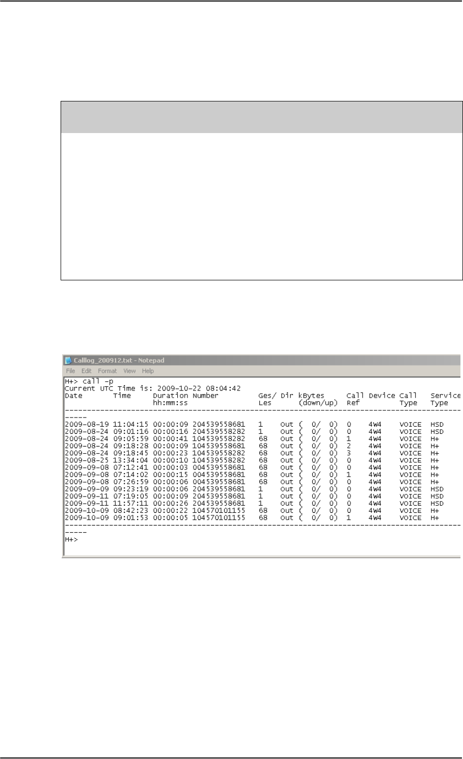
Commands for troubleshooting the SDU
F-6 Appendix F: Using terminal commands 98-124743-F
Call Log (“call_log” command)
To access the call log, use the call_log command.
The following options are available with the call_log command:
Response example:
The following example shows a part of a response to the command “call -p”:
Figure F-2: Troubleshooting SDU, Call Log command: call -p
Flight Test (“flight” command)
To trace flight data, use the flight command. The flight test data comprises position data,
signal strength and EIRP.
The following options are available with the flight command:
Command to Type in
(Followed by <Enter>) Result/Explanation
call_log -p Prints the call log.
call_log -i <number>
<device>
Inserts a call into the call log, with the given phone
number and device number.
call_log -g <device> Returns the last call in the call log from the given
device.
call_log -d <device>
<index>
Deletes the call with index <index> from the given
device in the call log.
call_log -c Clears the call log.
Table F-3: “call_log” Commands

Commands for troubleshooting the SDU
98-124743-F Appendix F: Using terminal commands F-7
Response example:
The following example shows a response to the command “flight -s”, that is flight test
data with an update rate of 1 second. The command “flight -e” stops the tracing.
H+> flight -s
H+> Fri Aug 27 12:26:32 2004 H+Temp 44
NAV POS: Lon 9.13, Lat 55.73, Alt 117 m
NAV ATT: Roll 0.41, Pitch -0.97, Hea 135.71, Speed 0 m/s
DSP: Azi 73.11, Ele 23.60, VDopp 0 m/s
PRT: C/No 54.0 EIRP 09.1 FreqOff 006
C0: C/No 45.1 EIRP 06.5
C1: C/No 54.1 EIRP 18.5
HSD: C/No 57.3 EIRP 22.5 FreqOff -01
--
flight -e
Command to Type in
(Followed by <Enter>) Result/Explanation
flight -c <time> Change the update rate to <time>.
flight -e End flight test traces.
flight -s Start trace of flight test data with an update rate of 1 second.
flight -s <time> Start trace of flight test data with an update rate of <time>.
The unit for <time> is 10 ms, that is: <time>=2 corresponds to
20 ms.
Table F-4: “flight” Commands

Commands for troubleshooting the SBU
F-8 Appendix F: Using terminal commands 98-124743-F
F.3 Commands for troubleshooting the SBU
F.3.1 Monitoring the ARINC interfaces on the SBU
Below is an example on how to get a status for the ARINC interfaces. After the debug
command for getting the status report (first line, bold) the status report is shown.
stat -m arinc
STAT Report
Module: ARINC, Status: Ok, Message:
REPORT: SHORT
CONFIGURATION
Primary Receiver : ARINC 704-7 Inertial Reference System (IRS), speed: High
Secondary Receiver: Disabled, speed: Low
Antenna Modem : Disabled
STATUS ARINC DRIVER
Current Time : Thu Jan 01 00:00:54 1970
Primary Receiver : 6 RO_6_IRS_CONNECTED Qualified Forwarding forwardingPeriods:1
Secondary Receiver: 0 RO_0_NULL Await-Label Standby forwardingPeriods:0
Antenna Modem : 1 RT_1_INIT Await-Label
Primary Receiver:
Label Status Error Active Age Value Name
101 No Label 422 0 0 0.000000 HDOP
150 No Label 422 0 0 00:00:00 gnss UTC Time
260 No Label 422 0 0 00/00/00 UTC Date
273 Normal 353 69 158 Self Test GNSS Sensor Status
274 Normal 353 69 158 Self Test GPIRS Status
310 Normal 353 69 158 55.794067 N Latitude
311 Normal 353 69 158 12.523041 E Longitude
312 Normal 353 69 158 0.000000 Knots Ground Speed
313 Normal 353 69 158 0.000000 Deg Track Angle True
314 Normal 353 69 158 0.000000 E True Heading
324 Normal 353 69 158 0.010986 Deg Pitch Angle
325 Normal 353 69 159 0.120850 Deg Roll Angle
336 Normal 353 69 159 -0.015625 Deg/Sec Inertial Pitch Rate
337 Normal 353 69 159 0.000000 Deg/Sec Inertial Roll Rate
361 Normal 353 69 159 167.250000 Feet Altitude Inertial
377 Plus 353 69 159 0x004 IRS (704) Equipment Identification
Details:
273 Satellites-Tracked:0 Visible:0
273 IRS/FMS : Present Source: Primary
273 DADC/FMS: Present Source: Primary
274 Satellites-Tracked: 0
274 Primary GPSSU Validity: Valid
274 Secondary GPSSU Validity: Valid
274 GPSSU Source: Primary
377 Source Identifier: Primary
COUNTERS ARINC-429: Primary Secondary Ant-Rx Ant-Tx
allocation 20 0 0
wordsA429 6752 0 0 0

Commands for troubleshooting the SBU
98-124743-F Appendix F: Using terminal commands F-9
discardError 0 0 0 0
framingError 0 0 0
parityError 0 0 0
overflowError 0 0 0
regStatusRead 422 0 0 FPGA Status Read
regTimeTagRead 422 0 0 FPGA TimeTag Read
regCtrlWrite 2 0 5 FPGA Control Write
interrupt 0 0 0 FPGA Interrupt
reset 0 0 0 0 Debug only
clearCounters 0 0 0 0
F.3.2 Description of the status report
The status report consists of up to seven parts:
1. Report header
2. ARINC driver configuration
3. The overall status for the ARINC driver
4. Status for the Primary ARINC Receiver
5. Status for the Secondary ARINC Receiver, if configured
6. Status for the ARINC Antenna modem, if configured
7. Low level ARINC-429 counters
Below is a detailed description of each part of the status report.
STAT Report
The following lines are part of the standard system header, there is no information relevant
for the ARINC interfaces present in the header, you may just ignore these lines:
STAT Report
Module: ARINC, Status: Ok, Message:
REPORT: SHORT
CONFIGURATION
The configuration part is a mirror of the ARINC information already available at Set up the
navigational input of the SBU on page 6-51, SETTINGS > External systems of the SBU.
STATUS ARINC DRIVER
Current Time: This is the current UTC time, if available. In this example the year 1970
indicates that the UTC time not yet is available.
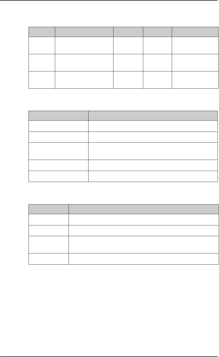
Commands for troubleshooting the SBU
F-10 Appendix F: Using terminal commands 98-124743-F
Read the following overview information in the following way:
Table F-5: Status ARINC driver, overview
Interface State number and name Status Source Source Activations
Primary
Receiver
6 RO_6_IRS_CONNECTED Lost-Label Forwarding forwardingPeriods:1
Secondary
Receiver
0 RO_0_NULL Await-Label Standby forwardingPeriods:0
Antenna
Modem
1 RT_1_INIT Await-Label
The states for receivers have the following purpose:
Table F-6: Purpose of the states for receivers
State name Description
RO_0_NULL The receiver is not configured and therefore not started.
RO_1_INIT The receiver is in the progress of starting up.
RO_2_LOOPBACK A loop back test command has been running and a power-
cycle is needed.
RO_4_AHRS_CONNECTED The AHRS driver is running.
RO_6_IRS_CONNECTED The IRS driver is running.
The states for the antenna modem can be used for the following purpose:
Table F-7: Purpose of the states for the antenna modem
State name Description
RT_0_NULL The antenna modem is not configured and therefore not started.
RT_1_INIT Awaits the BSU (Beam Steering Unit) start sending the status word.
RT_2_LOOPBACK A loop back test command has been running and a power-cycle is
needed.
RT_3_AMT50 The ARINC AMT-50 / HGA-6000 driver is running.
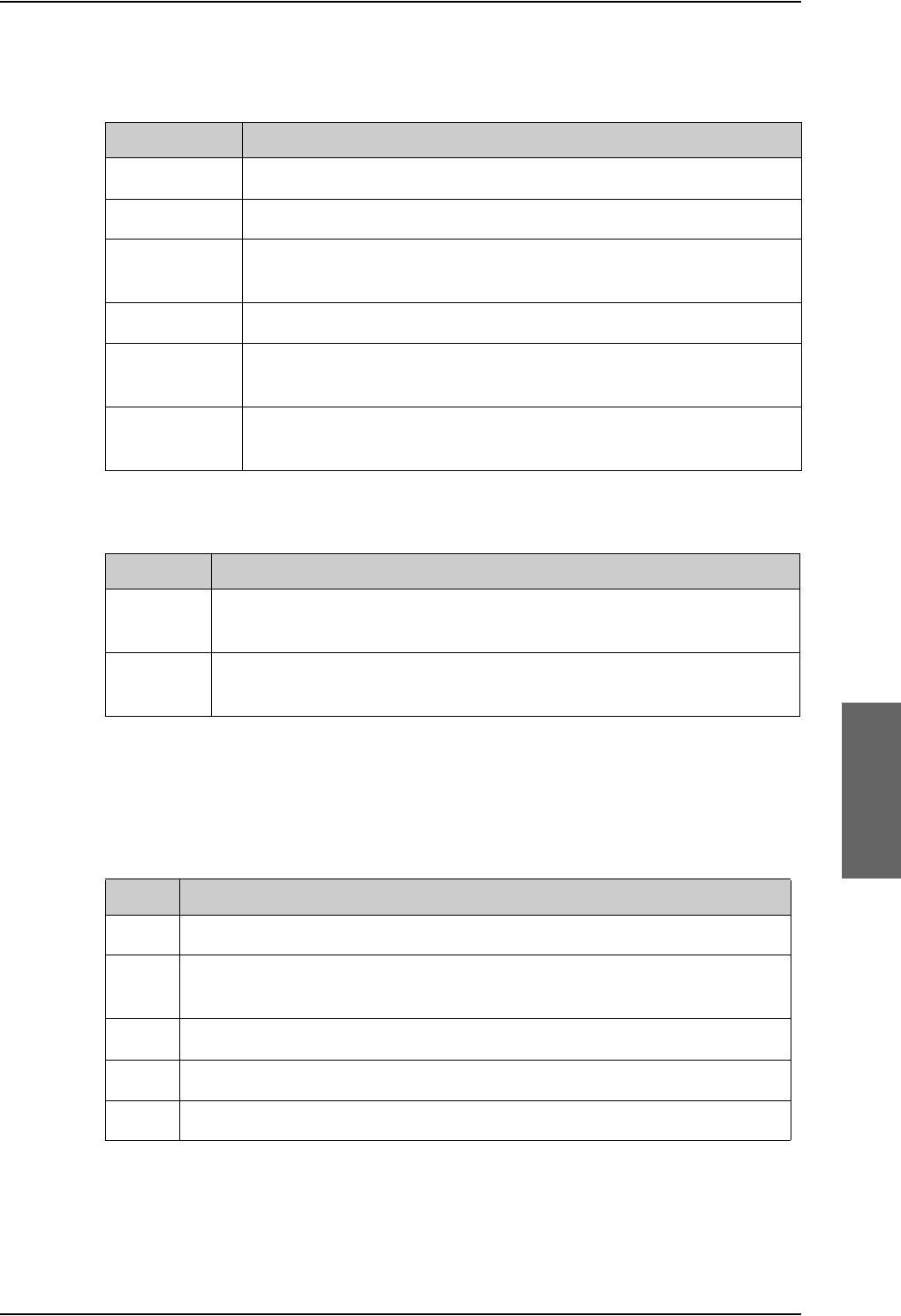
Commands for troubleshooting the SBU
98-124743-F Appendix F: Using terminal commands F-11
Status: This reflects the overall status considering all mandatory labels on the interface in
question.
Table F-8: Status for all mandatory labels on the interface in question
Status Description
Await-Label At least one mandatory label has never showed up on the interface.
Lost-Label A label previously received is now missing on the interface.
Unreliable May be used in the future for selecting between two channels where
one of them is more degraded than the other.
Degraded One or more of the labels is degraded.
Evaluation All mandatory labels are operational and has to be stable for a period of
time before they can be qualified.
Qualified All mandatory labels are operational and this port can now be
forwarded.
Source:
Table F-9: Status ARINC driver: Source
Source Description
Forwarding This ARINC receiver is forwarding valid navigational date to the SBU.
Forwarding means that the data on the interface is used by the system.
Standby This ARINC receiver is on standby and not forwarding data to the SBU.
Standby means that the data on the interface are not used by the system.
Forwarding Periods: The number of periods the interface has being forwarding data to
the system.
RECEIVER
Header Description
Label The label number in octal number system.
Status Take status of the label word according to bit 30 and 31 Sign/Status Matrix.
See table directly below.
Error The number of 100mS interval the label has not been operational.
Active The number of 100mS interval the label has been operational.
Age The age of the label in ms sampled every 100 ms.
Table F-10: Receiver: Header line for the table

Commands for troubleshooting the SBU
F-12 Appendix F: Using terminal commands 98-124743-F
The specific label type (BCD/BNR/DISC) can be looked up in the ARINC-429 Specification.
Table F-11: Status for label types
Status BCD BNR DISC
0Plus Failure Normal
1No Data No Data No Data
2Test Test Test
3Minus Normal Failure
The underlined status is the operational state for the specific label type.
Value The decoded value of the label
Name The name of the label according to ARINC-429
Header Description
Table F-10: Receiver: Header line for the table (Continued)

98-124743-F G-1
Appendix G
References G
G.1 Applicable standards
[1] IEEE Standard for Information technology - Telecommunications and information
exchange between systems - Local and metropolitan area networks - Specific
requirements Part 3: Carrier sense multiple access with collision detection
(CSMA/CD) access method and physical layer specifications. IEEE Std 802.3, 2000
Edition (Incorporating IEEE Std 802.3, 1998 Edition, IEEE Std 802.3ac-1998, IEEE
Std 802.3ab-1999, and IEEE Std 802.3ad-2000) [Adopted by ISO/IEC and re-
designated as ISO/IEC 8802-3:2000(E)].
[2] ISO/IEC 8877:1992 Information technology -- Telecommunications and information
exchange between systems -- Interface connector and contact assignments for
ISDN Basic Access Interface located at reference points S and T
[3] RTCA/DO-160C and RTCA/DO-160D. Environmental Conditions and Test Procedures
for Airborne Equipment. RTCA Inc. July 29, 1997, incl. Change No. 1 (Dec. 14, 2000)
and Change No. 2 (June 12, 2001)
[4] RTCA/DO-160E. Environmental Conditions and Test Procedures for Airborne
Equipment. RTCA Inc. December 9, 2004
[5] Integrated Services Digital Network (ISDN). Basic User-Network Interface (UNI). ETSI
EN 300 012-1 V1.2.2 (ITU I.430))
[6] Integrated Services Digital Network (ISDN). ISDN User Network Interfaces. ITU-T
Recommendation I.420
[7] ARINC 429. Mark 33 Digital Information Transfer Systems (DITS)
[8] ARINC 404A. Air Transport Equipment Cases and Racking
[9] ARINC 404B-1. Connectors, Electrical, Rack and Panel, Rectangular, Rear Release
Crimp Contacts.
[10] ARINC 702A-1. Advanced Flight Management Computer System. ARINC, January 31,
2000
[11] ARINC 741 P1-10. Aviation Satellite Communication System. Part 1, Aircraft
Installation Provisions
[12] ARINC 741 P2-7. Aviation Satellite Communication System. Part 2, System Design
and Equipment Functional Description
[13] RFC 1549: PPP in HDLC Framing. December 1993. (Obsoleted by RFC 1662)

Other references
G-2 Appendix G: References 98-124743-F
[14] CCITT Rec. G.473. Standard US DTMF Telephone
[15] RTCA/DO-178B. Software Considerations in Airborne Systems and Equipment
Certification, December 1, 1992
[16] RTCA/DO-254. Design Assurance Guidance for Airborne Electronic Hardware, April
19, 2000
[17] ARINC CHARACTERISTIC 704A. Inertial Reference System
[18] ARINC CHARACTERISTIC 705. Attitude and Heading Reference System
[19] ARINC CHARACTERISTIC 743A. GNSS Sensor
[20] ARINC CHARACTERISTIC 741P1. Aviation Satellite Communication System Part 1.
Aircraft installation provisions
[21] ARINC CHARACTERISTIC 781. Mark 3 Aviation Satellite Communication Systems
[22] EIA/TIA-232-E: Interface Between Data Terminal Equipment and Data Circuit-
Terminating Equipment Employing Serial Binary Data Interchange (superseded by
TIA-232-F) Published: January 1, 1900. Category: Telecommunications.
G.2 Other references
[23] AVIATOR 700 User Manual.
See also Related documentation on page 1-2.

98-124743-F Glossary-1
Glossary
Glossary 8
A
ACARS Airborne Communications Addressing and Reporting System
ACAS Aircraft Collision Avoidance System. Early relative of the now operational
TCAS (Traffic Alert and Collision Avoidance System) which warns pilots of
potential conflicts with other aircraft.
ACP Audio Control Panel
ACU Antenna Control Unit
ADF Automatic Direction Finder. A navigation receiver based on the AM radio
band. A very simple device which literally points towards the station that is
tuned in.
AES Aircraft Earth Station
AFIS Airborne Flight Information System
AHRS Attitude and Heading Reference System
ALC Automatic Level Control
AMBE Advanced Multi-Band Excitation
AMER Americas (Satellite coverage)
AMS Audio Management System
AOC Aeronautical Operational Control
AORE Atlantic Ocean Region East (Satellite coverage)
AORW Atlantic Ocean Region West (Satellite coverage)
APAC Asia Pacific (Satellite Coverage)
APN Access Point Name. The Access Point Name is used by the terminal operator
to establish the connection to the required destination network.
APS Aircraft Power Supply
ARINC Aeronautical Radio, Incorporated. A provider of transport communications
and systems engineering solutions
AT AT commands are used for controlling modems.
ATS Air Traffic Service
AWG American Wire Gauge

Glossary
Glossary-2 98-124743-F
B
BGAN Broadband Global Area Network
BITE Built-In Test Equipment. A BITE error is a hardware error detected by the
automatic error detection system in the AVIATOR 700 System.
BP Bottom Plug
C
C-FDM C-channel Frame Demodulator/Modulator
CID Context Identifier
CM Configuration Module
CMU Communications Management Unit
CP Cockpit
CPU Central programming Unit
CRC Cyclic Redundancy Check
CS Circuit switched
D
DCE Data Communication Equipment. Equipment that does not generate data,
but only relays data generated by someone else.
DHCP Dynamic Host Configuration Protocol. A protocol for assigning dynamic IP
addresses to devices on a network. With dynamic addressing, a device can
have a different IP address every time it connects to the network.
DME Distance Measuring Equipment
DSP Digital Signal Processor
DTE Data Terminal Equipment
DTMF Dual Tone Multi Frequency. The signal to the phone company that is
generated when you press an ordinary telephone’s touch keys. DTMF has
generally replaced loop disconnect (pulse) dialing.
E
ECS Electronic Cable Specialists, Inc., a Carlisle IT company
EEPROM Electronically Erasable Programmable Read Only Memory
EIA Electronic Industries Alliance. A US national trade organization that includes

Glossary
98-124743-F Glossary-3
the full spectrum of U.S. manufacturers, representing more than 80% of the
electronics industry. The alliance provides several standards for the
electronics industry.
EIRP Effective Isotropic Radiated Power
EMC Electromagnetic Compatibility
ETSI European Telecommunication Standard Institute
F
FAA Federal Aviation Administration
FNBDT Future Narrowband Digital Terminal. A US Government standard for secure
voice communication.
FPGA Field Programmable Gate Array
G
GES Ground Earth Station.
GND Ground
GPS Global Positioning System
H
HGA High Gain Antenna
HPA High Power Amplifier
HPR High Power Relay
HS High Speed
HSD High Speed Data
I
I/O Input/Output
IAI-2 Inmarsat Air Interface-2. The air interface used for BGAN. IAI-2 is an
evolution of MPDS with new bearer types, which give a wide range of data
rates from 16 kbps up to 492 kbps. By utilizing different modulation
schemes, variable coding rate and power adjustment, it is possible to change
the bearer type to give optimum throughput with efficient use of the
satellite resources.
ICAO International Civil Aviation Organization

Glossary
Glossary-4 98-124743-F
IEEE Institute of Electrical and Electronics Engineers
ILS Instrument Landing System. A system of tightly focused transmitters
located at the end of a runway that provides flight guidance information to
flight crews.
IMEI International Mobile Equipment Identity. A unique number identifying your
terminal
IMSI International Mobile Subscriber Identity
IOR Indian Ocean Region (Satellite coverage)
IP Internet Protocol
IRS Inertial Reference System
ISDN Integrated Services Digital Network
ISN Inmarsat Serial Number
ISP Internet Service Provider
ITU International Telecommunication Union
K
kbps kilobit per second, unit of data transfer rate
L
LAN Local Area Network
LED Light Emitting Diode
LES Land Earth Station.
LRU Line Replaceable Unit. A separate unit or module which can easily be
replaced. Examples are the SDU and the HPA.
LS Low Speed
M
MCDU Multifunction Control and Display Unit. Part of the Flight Management
System.
MEAS Middle East, Asia (Satellite coverage)
MES Mobile Earth Station
MIB Management Information Base

Glossary
98-124743-F Glossary-5
MOD Modification
MSN Multiple Subscriber Numbering. In most pieces of ISDN equipment you can
program multiple subscriber numbers. The number programmed into the
equipment should be the dial-in number that you wish that piece of
equipment to answer.
N
NAT Network Address Translation. An Internet standard that enables a local-area
network to use one set of IP addresses for internal traffic and a second set
of addresses for external traffic. A NAT module makes all necessary address
translations.
NC No Connect
NCS Network Coordination Station
nON Power-on control signal, active low
NT Network Termination. A device connecting the customer’s data or
telephone equipment to the local ISDN exchange carrier’s line. It provides a
connection for terminal equipment (TE) and terminal adaptor (TA)
equipment to the local loop.
P
PAST Person Activated Self Test
PBX Private Branch Exchange, telephone exchange that serves a particular
PC Personal Computer
PDF Portable Document Format, a file format created by Adobe Systems for
document exchange
PDP Packet Data Protocol. A network protocol used by external packet data
networks that communicate with a GPRS network.
PID Packet IDentifier
POR Pacific Ocean Region (Satellite coverage)
POST Power On Self Test. A system test that is activated each time the system is
powered on.
POTS Plain Old Telephony System. Traditional 2-wire system.
PS Packet switched
PSM Phase Shift Modulation
PTT Push-To-Talk

Glossary
Glossary-6 98-124743-F
Q
QoS Quality of Service
R
RAM Random Access Memory
RF Radio Frequency
RFHP Radio Frequency High Power
RTCA Radio Technical Commission for Aeronautics
S
SATCOM Satellite Communications
SB Swift Broadband, based on BGAN and offers similar services, simultaneous
voice and broadband data.
SBU SwiftBroadband Unit. Unit in the satcom system providing access to the
aeronautical BGAN service, SwiftBroadband.
SCPC Single Channel Per Carrier. A VSAT satellite transmission system that uses a
separate carrier for each of its channels. In an SCPC system, transmissions
are sent to the satellite continuously on a single satellite carrier.
SDM System Definition Manual
SDU Satellite Data Unit. The controlling unit of the AVIATOR 700 system.
SDU Service Data Unit. Also known as a data packet.
SIM Subscriber Identification Module
SIP Session Initiation Protocol. An application-layer control (signaling) protocol
for creating, modifying, and terminating sessions with one or more
participants. Used e.g. for Internet telephony.
SLCV S = coding Standard, L = cause Location, C = cause Class, V = cause Value
SNMP Simple Network Management Protocol. An Internet-standard protocol for
managing devices on IP networks. It is used mostly in network management
systems to monitor network-attached devices for conditions that warrant
administrative attention.
SSID Service Set IDentifier. An SSID is the name of a wireless local area network
(WLAN). All wireless devices on a WLAN must use the same SSID in order to
communicate with each other.
STBO Starboard
STC Supplemental Type Certificate. FAA or EASA certification document issued

Glossary
98-124743-F Glossary-7
to companies that perform significant modifications on an aircraft.
STE Secure Terminal Equipment
STU Secure Telephone Unit
T
TC Type Certificate
TCAS Traffic Alert and Collision Avoidance System. A system which warns pilots
of potential conflicts with other aircraft.
TDM Time Division Multiplex
TE Terminal Equipment
TFTP Trivial File Transfer Protocol. A very simple file transfer protocol, with the
functionality of a very basic form of FTP. Since it is so simple, it is easy to
implement in a very small amount of memory.
TIA Telecommunications Industry Association. TIA is a U.S. non-profit trade
association serving the communications and information technology
industry. TIA provides several standards for these industries.
TP Top Plug
V
VFC Voice Fax Codec
VHF Very High Frequency. 30-300 MHz, a "straight-line" signal used for
communication and navigation.
VOR VHF Omnidirectional Range
W
WLAN Wireless Local Area Network
WOW Weight On Wheels

Glossary
Glossary-8 98-124743-F

98-124743-F Index-1
Index
Index 9
Numerics
2.4GHz Cordless phone
wiring (4-wire), 5-60
2-Wire Cradle
connector functions, 4-23
DB9 male connector, 4-23
Environmental Qualification Form, B-13
outline drawing, 3-13
specifications, A-12
2-Wire Handset
Environmental Qualification Form, B-13
outline drawing, 3-12
specifications, A-12
2-wire interface
setting call type, 6-34
4-Wire Cradle
connector functions, 4-20
DB15 male connector, 4-20
Environmental Qualification Form, B-11
outline drawing, 3-11
specifications, A-11
4-Wire Handset
Environmental Qualification Form, B-11
outline drawing, 3-10
specifications, A-10
A
about this manual, 1-1
ACARS
wiring, 5-35
Access Point Name, 6-37
activation
SIM card, 5-87
additional numbers
description, 6-89
enter, 6-26
address
manufacturer, -ii
administration settings, 6-68
administration, remote, 6-86
administrator
log off, 6-71
log on, 6-69
password, reset, 6-71
advanced configuration
WLAN, 6-31
Aero-SDU CP
basic configuration, 6-9
installation requirements, 6-2
software version, 8-8
AES ID, 5-86
AFIS
wiring, 5-35
AHRS
navigational input, 5-6
wiring, 5-32
air interface
status, 8-25
aircraft
interfaces, 4-16
mating connectors, 4-24
airtime services, 5-86
Airworthiness, Continued, 8-1
alarms
log, 8-24
view, 8-24
AMT-50 subsystem
wiring, 5-18
annunciators
default setting, 4-16
wiring, 5-65
antenna
GPS distance, 5-7
mounting, 5-6
systems, 2-8
viewing properties, 6-27
viewing status, 6-22
viewing type, 6-22, 8-25
wiring, 5-17
antenna steering, 5-6
APN, 5-87
common, 6-37
setup, 6-37, 6-38
ARINC
stat command, F-8
stat report, F-8
ARINC 404
connectors, 4-12
ARINC 429
wiring, 5-32

Index
Index-2 98-124743-F
ARINC 741 antenna system
cable requirements, 5-21
wiring, 5-18
ARINC 741 dual side panel antenna system
wiring, 5-22
assigned numbers, 6-89
assistance, telephone number, 8-1
AT commands, 6-85
ATE pins, 5-79
automatic test equipment pins, 5-79
AVIATOR Wireless Handset
connect, 6-44
setup, 6-45
setup call types, 6-46
B
backup.configuration, 6-71
barring calls, 6-40
bit error ratio, 6-78
BITE codes
list of, D-16
severity levels, D-15
block diagrams, 2-15
ARINC 741 compatible antenna, 2-16
dual side panel antenna system, 2-18
Broadcast SSID, 6-32
browser settings
for web interface, 6-20
browsers supported, 6-16
buttons
Push To Test, 8-18
C
cable loss, 6-50
RF cables, 5-17
cable specification
SBU maintenance connector, 4-13
cables
allowed lengths for power, 5-81
ARINC 429, 5-36
ARINC 429, recommended types, 5-85
ARINC 741 antenna system, 5-21
discrete signals, 5-85
Ethernet, 5-85
Ethernet, recommended, 5-85
HPA power supply, 5-15
ISDN, requirements, 5-46
maximum length, SBU to HLD, 5-84
maximum length, WLAN, 5-84
power, recommended types, 5-83
recommended, 5-81
RF, general requirements, 5-7
RF, recommended types, 5-84
RS-232 data cable, 5-78
SBU power supply, 5-17
SDU power supply, 5-12
WLAN, max. length, 5-84
call charges
calls, 6-74
call limiting, 6-88
call log
clear, 6-75
Call output, 6-48
call type
setting for AVIATOR Wireless Handset, 6-46
setting for ISDN, 6-35
setting for Phone/Fax interface, 6-34
calls
barring, 6-40
closed user group, 6-43
forwarding, 6-39
line identification, 6-42
ongoing, 8-25
viewing ongoing, 6-23
waiting indication, 6-41
Cause codes
H+, D-2
ISDN (SLCV), D-8
Cause codes, list, D-2
charges
calls, 6-74
data sessions, 6-74
check procedures, 7-1
after power-up, 7-4
airborne, 7-7
before inserting LRUs, 7-2
interference with other systems on aircraft, 7-
6

Index
98-124743-F Index-3
Chime/Lamps Inhibit
configuration, 6-47
wiring, 5-65
Circuit breaker
specifications, 2-13
circuit breaker, 5-16
clearing logs, 6-75
clearing usage counter, 6-75
closed user group, 6-43
CM
DO-160 form, B-9
Environmental Qualification Form, B-9
CMU, wiring, 5-35
Coax, 5-9
Cockpit reserve, 6-92
Cockpit Voice
wiring, 5-69
common network settings, 6-37
compliance, 2-1
configuration
cable losses, 6-50
discrete I/O, 6-48
exporting to file, 6-71
importing from file, 6-72
input of navigational systems, 6-51
ISDN, 6-35
LAN, 6-28
phone systems, 6-96
phone, fax, 6-34
step-by-step, 6-17
upload, 6-72
web interface, 6-12
WLAN, 6-31
configuration data
enter, 2-8, 6-16
Configuration Module, 2-7
DO-160 form, B-4
Environmental Qualification Form, B-4
outline drawing, 3-3
configuration of SBU
backup, 6-71
Configuration Program, 6-1
connect
AVIATOR Wireless Handset, 6-44
connection
standard data, 6-24
start or stop, 6-24
connectors, 4-1
2-Wire Cradle, 4-23
4-Wire Cradle, 4-20
ARINC 404, 4-12
Configuration Module, 4-12
HPA receptacle, 4-10
Maintenance front, 4-12
mating, in aircraft, 4-24
part number, 2-13
SBU front, 4-12
SBU rear receptacle, 4-14
SDU front, 4-2
SDU rear receptacle, 4-4
contact
address, -ii
contact information, 8-5
Continued Airworthiness, 8-1
cooling requirements, 5-5
counter reset, 6-75
Country
selecting for WLAN, 6-32
country code
WLAN, default, E-1
WLAN, US, E-2
Coupler
outline drawing, 3-7
specifications, A-8
D
dashboard, 6-22
data
profiles, 6-75
traffic flow filters, 6-79
data cable for RS-232 front connection, 5-78
data limits, 6-75
data rates, 2-4
data sessions
cost, 6-74
viewing ongoing, 6-23
debug command
ARINC, F-8
default button, 8-22
default netmask, 8-23
defect units, 8-2
DHCP, 6-28
no router option, single user, 6-28
DHCP request, 6-24
diagnostic report, 8-6, 8-26

Index
Index-4 98-124743-F
dimensions
HLD, A-7
SBU, A-6
direct dial
local phone, 6-44
disable
WLAN, 6-31, 6-53
discrete I/O
configuration, 6-48
discretes
types and description, 5-68
wiring, 5-65
DO-160 forms, B-1
2-Wire Handset and Cradle, B-13
4-Wire Handset and Cradle, B-11
CM, B-9
Configuration Module, B-4
HPA, B-5
SBU, B-7
SDU, B-2
drawings, 3-1
2-Wire Cradle, 3-13
2-Wire Handset, 3-12
4-Wire Cradle, 3-11
4-Wire Handset, 3-10
Configuration Module, 3-3
HPA, 3-4
HPA Tray, 3-15
HPA Tray connector, 3-19
Rx Power Splitter, 3-8
SBU, 3-5
SBU Tray connector, 3-20
SDU, 3-2
SDU Tray, 3-15
SDU Tray connector, 3-18
Tx Coupler, 3-7
dual side panel antenna system
wiring, 5-22
E
electrical installation, 5-9
enable, 6-31
SBU, 5-30
WLAN, 6-31
encryption key, 6-33
Environmental Qualification Forms, B-1
2-Wire Handset and Cradle, B-13
4-Wire Handset and Cradle, B-11
CM, B-9
Configuration Module, B-4
HPA, B-5
SBU, B-7
SDU, B-2
error codes, D-1
error correction for data packets, 6-78
Ethernet interface
setting up, 6-28
Eval.Prec. Index, 6-80
events
list of, D-28
list of active, 8-24
exchanging units, 8-2
exporting configuration, 6-71
extended status, 8-7, 8-25
external access, 6-86
F
factory settings, 8-23
Fail/Pass LED
HPA, 8-20
SDU, 8-19
Fail/Pass LED, SBU, 8-21
features, 2-9
FLEX key sequence, 6-52
forwarding calls, 6-39
front connector
SBU, 4-12
SDU, 4-2
functional test, airborne, 7-7
functional test, on ground, 7-4
G
GPS antenna
distance from antenna, 5-7
input, 4-16
interference, 5-7
wiring, 5-37
ground speed, 5-34

Index
98-124743-F Index-5
H
H+ number, 5-86
handset contexts for Multi-voice, 6-89
handsets
AVIATOR Wireless, configuration, 6-44
initial configuration, 6-96
wiring, 5-47
header compression, 6-62
heading, 5-34
magnetic, 5-34
help desk number, 8-6
changing in web interface, 8-6
helpdesk
telephone number, 8-1
HLD
dimensions, A-7
hotline
telephone number, 8-1
HPA
DO-160 form, B-5
Environmental Qualification Form, B-5
LEDs on front panel, 8-20
mating connectors for, 4-25
mounting, 5-6
outline drawing, 3-4
power cables, 5-15
power supply, wiring, 5-13
rear receptacle, 4-10
specifications, A-4
Tray connector, outline drawing, 3-19
HSD+ upgrade, 2-14
I
IAI
air interface status, 8-25
ICAO, 5-86
ICAO address, 24 bit discrete, 5-38
ICAO, wiring, 5-37
ICG DECT Cordless Handset
initial configuration, 6-96
wiring (2-wire), 5-64
ID
SBU software, 8-14
SDU software, 8-14
ID numbers, 5-86
IMEI number, 6-22
importing configuration, 6-72
Inmarsat service number, 5-86
inoperative units, 8-2
input
GPS antenna, 4-16
installation kit
contact information, 2-14
part number, 2-13
upgrade HSD+ to AVIATOR 700, 2-14
installation kits
supplier, 5-1
interface
SNMP, 6-68
WLAN, disable, 6-53
interface for software upgrades, 4-13
interfaces, 5-1
user, 2-20
interference
GPS antenna, 5-7
IP address, 8-22
default, 8-22
external, setting up, 6-57
for connected device, 6-59
for web interface, 6-18
local, setting up, 6-29
local, viewing, 6-22
reset, 8-22
IP connection
monitoring, 6-87
IP data
streaming rate, 2-5
IP handset
setting call type, 6-46
setting up, 6-44
Iridium ICS-200
wiring, 5-57
IRS
navigational input, 5-6, 6-51
wiring, 5-32
ISDN
cable requirements, 5-46
Cause codes (SLCV), D-8
interface description, 5-46
pins, 5-45
setup, 6-35
wiring, 5-45
ISDN interface
setting up, 6-35
ISDN routing
phone, fax and data, 5-48
ISN, 5-86

Index
Index-6 98-124743-F
L
lamp driver interface
specifications, 5-68, 5-69
LAN
managing network users, 6-54
setting up interface, 6-28
setup, 6-28
LAN communication, 6-24
LEDs on HPA
Fail/Pass, 8-20
Power, 8-20
LEDs on SBU
Fail/Pass, 8-21
Logon, 8-20
Maintenance connector, 8-21
Power, 8-20
system ready, 6-100, 6-101
LEDs on SDU
Fail/Pass, 8-19
Logon, 8-19
Power, 8-19
limit calls, 6-88
limiting
data services, 6-75
streaming, 6-75
line identification, 6-42
link monitoring, 6-87
local exchange, 6-44
Multi-voice, 6-44
location
SBU temperature controlled, 5-5
log off
administrator, 6-71
log on
administrator, 6-69
Logon LED
on SBU, 8-20
Logon LED, SDU, 8-19
logs, clearing, 6-75
low pass filter, 5-43
M
MAC address, 6-22
Maintenance connector
functional description, 4-13
LED, 8-21
PC and Reset, wiring, 5-76
pin-out, 4-13
Maintenance handset
wiring, 5-79
Maintenance interface
pin allocation, 5-78
manufacturer
address, -ii
MCDU
wiring, 5-35
menu tree, 6-17
messages, D-1
MIB files, 6-68
minimum setup
SBU, 6-12
SDU, 6-9
minimum system
drawing, 5-3
mobile numbers
viewing and editing, 6-25
model numbers, applicable, 2-11
monitoring external IP connection, 6-87
mounting considerations, 5-5
antenna, 5-6
HPA, 5-6
Rx Power Splitter, 5-5
SBU, 5-5
SDU, 5-5
WLAN antenna, 5-8
MSN number, 6-35
Multi-voice, 2-9, 6-26, 6-92
additional numbers, 6-89
additional numbers, assign to 2-wire, 6-34
additional numbers, assign to AVIATOR
Wireless Handset, 6-46
additional numbers, assign to ISDN, 6-35
handset contexts, 6-89
local exchange, 6-44
N
NAT, 6-63
NAV source
wiring, 5-32
navigation in web interface, 6-19
navigational input, 5-3
AHRS/IRS, 5-6, 6-9
enter in configuration, 6-51
IRS in SBU, 6-51
SBU, 6-16
wiring, 5-32

Index
98-124743-F Index-7
netmask
default, 8-23
Network Address Translation, 6-63
network management, 6-54
network terms
definitions, 6-62
non-safety interfaces, 2-2
O
operation, 2-22
options
FLEX keys, 6-52
outline drawings, 3-1
P
packaging for return, 8-30
part number
installation kit, 2-14
part numbers, 2-11
connector, 2-13
installation kit, 2-13
PAST, 8-17
PBX unit, 2-7
PC, Maintenance
wiring, 5-76
PDP context, 6-24
permissions
user, 6-84
Person Activated Self Test, 8-17
phone book, 6-25
phone numbers for terminal, 6-25
Phone/Fax
setup, 6-34
Phone/Fax interface
setting call type, 6-34
phonebook
limit calls to, 6-88
phones
wiring, 5-47
PIN
administration PIN, 6-69
ping command from SBU, 6-87
pin-out, 4-1
2-Wire Cradle, DB9 connector, 4-23
4-Wire Cradle, DB15 connector, 4-21
HPA receptacle, 4-11
ISDN, 5-45
Maintenance interface, 5-78
SBU front connector, 4-13
SBU rear receptacle, 4-17, 4-18
SDU front connector, 4-3
SDU rear receptacle, 4-6
pitch angle, 5-34
pitch rate, 5-34
port forwarding, 6-29
POST, 8-17
POTS interface
configuration, 5-48
power cables, 5-17
recommended, 5-83
Power LED
on HPA, 8-20
on SBU, 8-20
on SDU, 8-19
Power On Self Test, 8-17
power splitter
DO-160 string, B-9
equipment drawing, 3-8
specifications, A-9
PPPoE
connection, 6-64
network connections, 6-65
setup, 6-65
setup equipment, 6-65
PPPoE setup
non-default APN, 6-66
profiles for data transmission, 6-75
properties
antenna, 6-27
system, 6-22
protect
change of SBU setup, 6-84
protection
SBU setup, 6-68
protocol number, 6-81
provisioning, 5-87
Proxy server, disabling, 6-20
Push To Test button, 8-18
Q
QoS, 6-75

Index
Index-8 98-124743-F
Quadrax connector
wiring, 5-42
Quality of Service, 6-75
quick start
SBU, 6-12
SDU, 6-9
R
rear receptacle
HPA pin-out, 4-11
SBU pin-out, 4-17, 4-18
SDU pin-out, 4-6
reboot, 6-27, 8-25
references, G-1
remote control
SBU, 6-87
remote management, 6-86
Repackaging requirements, 8-30
repair, 8-2
returning units, 8-30
reports
distance, 6-53
interval, 6-53
position, 6-53
server connection, 6-53
Reset
wiring, 5-76
reset
default IP-address, 8-22
during self test, 8-25
password, 6-71
reset administrator password, 6-71
reset time counter for calls, 6-75
reset to factory settings, 8-23
residual bit error ratio, 6-78
restricted dialing, 6-46, 6-88
returning units, 8-30
RF cable requirements
WLAN, 5-44
RF settings
SBU, 6-9, 6-50
SDU, 6-9
roll angle, 5-34
roll rate, 5-34
router option
limit when not available, 6-17
limits in single user mode, 6-28
RS-232
data cable, 5-78
RS-232 Maintenance
wiring, 5-76
RTCA DO-160 forms, B-1
Rx Power Splitter
mounting, 5-5
outline drawing, 3-8
specifications, A-9
S
satcom antennas, 2-8
satellite
view selected, 6-22
SBU
configuration backup, 6-71
cooling, 5-5
dimensions, A-6
DO-160 form, B-7
Environmental Qualification Form, B-7
front connector, 4-12
front connector, pin-out, 4-13
location in aircraft, 5-5
mating connectors for, 4-25
maximum cable length, 5-84
mounting, 5-5
outline drawing, 3-5
power cables, 5-17
protect for setup change, 6-84
quick start, 6-12
rear receptacle, 4-14
remote control, 6-87
software version, 8-8
specifications, A-6
Tray connector, outline drawing, 3-20
SBU Enable, 5-30
SBU Failed, 5-66, 6-47
SBU nON, 5-68
SBU nOn
remote on/off, 5-68
SBU setup
protection, 6-68
SBU software ID, 8-14

Index
98-124743-F Index-9
SDU
DO-160 form, B-2
Environmental Qualification Form, B-2
front connector, 4-2
LEDs on front panel, 8-19
mating connectors for, 4-24
mounting, 5-5
outline drawing, 3-2
power cables, 5-12
power supply, wiring, 5-10
quick start, 6-9
rear receptacle, 4-4
rear receptacle, pin-out, 4-6
software version, 8-8
specifications, A-2
Tray connector, outline drawing, 3-18
SDU and HPA Tray
outline drawing, 3-15
SDU software ID, 8-14
security key
wireless network, 6-33
self test, 8-25
serial number, 6-22
server connection
reports, 6-53
Service Available, 6-47
service log, 8-5, 8-26
service numbers, 5-86
services
supplementary, 6-35
services available, 2-4
sessions
ongoing, 8-25
SETTINGS page, 6-27
setup, 5-87
AVIATOR Wireless Handset, 6-45
SBU minimum, 6-12
SDU minimum, 6-9
show number, 6-42
Sigma7 handsets
initial configuration, 6-96
wiring, 5-63
SIM card activation, 5-87
SIM default, 6-37
SIM Lock, 6-82
SIM PIN, 6-82
single user, 6-28
single-user mode, 6-28
SIP telephony, 5-47
site map, 6-95
SLCV codes, D-8
SMS control
SBU, 6-87
SNMP, 6-68
software
viewing version, 6-22
software identification
SBU label, 8-14
SDU label, 8-14
software update, 8-8
software upgrades
interface, 4-13
software version
minimum, 8-8
specifications, A-1
2-Wire Cradle, A-12
2-Wire Handset, A-12
4-Wire Cradle, A-11
4-Wire Handset, A-10
circuit breaker, 2-13
HPA, A-4
Rx Power Splitter, A-9
SBU, A-6
SDU, A-2
Tx Coupler, A-8
WLAN antenna, A-7
Splitter
mounting, 5-5
outline drawing, 3-8
specifications, A-9
SSID, 6-32
standards, applicable, G-1
start connection, 6-24
static IP address
device connected to SBU, 6-28
static route, 6-67
status
air interface, 8-25
connection, 8-25
extended, 8-25
ongoing calls and data sessions, 6-23
viewing, 6-22
status information, 8-7
streaming
limit, 6-75
streaming rates, 2-5
supplementary services
setting up, 6-35
support
contact details, 8-1
contact information, 8-5
phone numbers, 8-1

Index
Index-10 98-124743-F
Swift 64 number, 5-86
SwiftBroadband number, 5-86
system drawing
minimum, 5-3
system messages, D-1
system ready, 6-100, 6-101
system type, 6-49
system, minimum, 2-11
T
tail number, 5-86
tariffs, 6-74
telephone interface
setting call type, 6-34
temperature controlled
SBU, 5-5
test procedures, 7-1
after power-up, 7-4
airborne, 7-7
before inserting LRUs, 7-2
interference with other systems on aircraft, 7-
6
time connected, 6-75
time counter
calls, reset, 6-75
total usage
viewing, 6-23
track angle, 5-34
tracking, 6-53
traffic class, 6-77
traffic flow filters, 6-79
Transfer delay, 6-78
troubleshooting, 8-17
diagnostic report, 8-6
service log, 8-5
Tx Coupler
outline drawing, 3-7
specifications, A-8
U
updating software, 8-8
upgrade
from HSD+, trays needed, 2-14
HSD+ to AVIATOR 700 installation kit, 2-14
upload configuration, 6-72
usage counter, 6-23
clearing, 6-75
user interfaces, 2-20
user permissions, 6-84
setup, 6-84
V
version of software, 6-22
voice mail number
viewing, 6-27
voice quality
setting for IP handsets, 6-46
setting for ISDN, 6-35
setting for Phone/Fax interface, 6-34
VoIP, 5-47
W
waiting calls, 6-41
warranty, 8-30
web interface
accessing, 6-16
browser settings, 6-20
configuration, 6-12
menu tree, 6-17
navigating, 6-19
WH-10 handsets
wiring, 5-54
Wifi
encryption key, 6-33
name, 6-32
Wireless Handset, 6-44
wireless LAN interface
setting up, 6-31
wireless local area network
name, 6-32

Index
98-124743-F Index-11
wiring, 5-1, 5-9
2.4GHz Cordless phone (4-wire), 5-60
ACARS, 5-35
AFIS, 5-35
AHRS and IRS, 5-32
AMT-50 subsystem, 5-18
annunciators, 5-65
antenna, 5-17
ARINC 429 interfaces, 5-32
ARINC 741 antenna, 5-18
Chime/Lamps Inhibit, 5-65
CMU, 5-35
Cockpit Voice, 5-69
data cable for front connector, 5-76
discrete annunciators, 5-65
dual side panel antenna, 5-22
GPS antenna, 5-37
HPA power supply, 5-13
ICAO, 5-37
ICG DECT Cordless Handset (2-wire), 5-64
Iridium ICS-200 interface, 5-57
ISDN, 5-45
Maintenance handset, 5-79
Maintenance PC and Reset, 5-76
MCDU, 5-35
NAV source, 5-32
phones and handsets, 5-47
Quadrax connector, 5-42
SDU power supply, 5-10
Sigma7 handsets, 5-63
symbols, 5-9
WH-10 handsets, 5-54
WLAN antenna, 5-43
wiring symbol
Coax, 5-9
Ground, 5-9
Shield, 5-9
Twisted and shielded, 5-9
WLAN
cable, max. length, 5-84
country code, 6-32
disable, 6-31, 6-53
enable, 6-31
encryption key, 6-33
interface description, 5-43
interface, setting up, 6-31
low pass filter, 5-43
maximum cable length, 5-84
RF cable requirements, 5-44
setup, 6-31
single antenna, 5-44
WLAN antenna
mounting, 5-8
recommended type, 5-8
specifications, A-7
wiring, 5-43
WLAN Enable, 5-68
WOW
SDU pins, 5-67

98-124743-F
www.cobham.com/satcom