Thrane and Thrane A S AVIATOR700 Satellite transceiver for Inmarsat Swift Broadband service User Manual AeroSB UserManual98 130578
Thrane & Thrane A/S Satellite transceiver for Inmarsat Swift Broadband service AeroSB UserManual98 130578
Contents
- 1. Installation Manual
- 2. Users Manual
Users Manual
AVIATOR 700/700D
User manual
i
AVIATOR 700/700D
User Manual
Document number: 98-130578-D
Release date: June 22, 2018
ii
Disclaimer
Any responsibility or liability for loss or damage in connection with the use of
this product and the accompanying documentation is disclaimed by Thrane &
Thrane A/S. The information in this manual is provided for information
purposes only, is subject to change without notice and may contain errors or
inaccuracies. Manuals issued by Thrane & Thrane A/S are periodically revised
and updated. Anyone relying on this information should acquire the most
current version e.g. from www.cobham.com/satcom, Cobham SYNC
Partner Portal, or from the distributor. Thrane & Thrane A/S is not
responsible for the content or accuracy of any translations or reproductions,
in whole or in part, of this manual from any other source. In the event of any
discrepancies, the English version shall be the governing text.
Thrane & Thrane A/S is trading as Cobham SATCOM.
Copyright
© 2018 Thrane & Thrane A/S. All rights reserved. Printed in Denmark.
Company address
Thrane & Thrane A/S, Lundtoftegaardsvej 93 D, DK-2800, Kgs. Lyngby,
Denmark
Trademark acknowledgements
•Inmarsat is a registered trademark of the International Maritime Satellite
Organisation (IMSO) and is licensed by IMSO to Inmarsat Limited and
Inmarsat Ventures plc.
•Windows and Outlook are registered trademarks of Microsoft
Corporation in the United States and other countries.
•WinPoET is a trademark of Fine Point Technologies, Inc.
• Other product and company names mentioned in this manual may be
trademarks or trade names of their respective owners.
Company web site
www.cobham.com/satcom

iii
Safety summary
The following general safety precautions must be observed during all
phases of operation, service and repair of this equipment. Failure to
comply with these precautions or with specific warnings elsewhere in this
manual violates safety standards of design, manufacture and intended
use of the equipment. Thrane & Thrane A/S assumes no liability for the
customer's failure to comply with these requirements.
Radio frequency radiation exposure information:
This equipment complies with FCC radiation exposure limits set forth for
an uncontrolled environment. This equipment should be installed and
operated with minimum distance of 200 cm between the radiator and
your body. This transmitter must not be co-located or operating in
conjunction with any other antenna or transmitter.
Antenna mounting
The antenna supplied by the manufacturer must be located such that
during radio transmission, no person or persons can come closer than the
minimum safe distance stated in the Radiation warning above. To comply
with current FCC RF Exposure limits, the antenna must be installed at or
exceeding the minimum safe distance shown above, and in accordance
with the requirements of the antenna manufacturer or supplier.
RADIATION WARNING
During transmission the antenna radiates Microwave power. High
levels of radio frequency radiation are considered harmful to
health. Although no single value has been agreed upon by all
countries, the American National Standards Institute (ANSI/IEEE
C95.1-1992) recommends that people should not be exposed to
radiation stronger than 1 milli Watt per square centimeter at the
frequencies used in this system. Accordingly, the operator of the
system should ensure that no person should approach within
200 cm from the sides and above the satcom antenna when the
system is transmitting.

iv
Disposal
Old electrical and electronic equipment marked with this symbol
can contain substances hazardous to human beings and the
environment. Never dispose these items together with unsorted
municipal waste (household waste). In order to protect the
environment and ensure the correct recycling of old equipment
as well as the re-utilization of individual components, use either
public collection or private collection by the local distributor of old electrical
and electronic equipment marked with this symbol.
Contact the local distributor for information about what type of return system
to use.
About the manual
Intended readers
This manual is a user manual for the AVIATOR 700 System. The readers of this
manual include aircraft personnel and passengers who want to use Classic
Aero, SwiftBroadband and Swift64 services.
For the daily use of the system there are no specific skills required. However, it
is important that you observe all safety requirements listed in this manual, and
operate the system according to the guidelines in this manual.
Manual overview
The manual contains the following chapters:
•Introduction - an overview of the Inmarsat Aero system and its services.
Also a brief description of the AVIATOR 700 system.
•Get started - a description of how to start up the system.
Note
The AVIATOR 700 system is available in two versions:
AVIATOR 700 approved to RTCA specification DO- 178B
level E and DO-254 level E
AVIATOR 700D approved to RTCA specification DO-178B
level D and DO-254 level D.
In general descriptions the nomenclature AVIATOR 700
covers both versions. Where necessary, the Level D
system is specified as AVIATOR 700D.
v
•Calls, faxes and SMS - a detailed description how to make calls, from
the Full Feature handsets or the MCDU (Multi-function Control and Display
Unit, how to send faxes and how to send and receive text messages. Also a
short description of other handsets.
•Use a computer – a description of how to connect and set up a
computer for using SwiftBroadband or Swift64 data services, including
LAN and WLAN connection, ISDN and MPDS connections, PPPoE and
analog modem connection.
•System operation with setup information for the Full Feature handset,
MCDU and the SwiftBroadband Unit.
•Troubleshooting – a short troubleshooting guide, a description of
system LEDS and error messages that may appear during operation. Also a
list of H+ Cause codes and information on where to get further help if
necessary.
Note that this manual does not cover the installation, configuration and setup
of the system. It does neither cover how to customize the system for specific
applications. For more detailed information how to set up interfaces and
configure network setup and routing functionality see the AVIATOR 700
Installation and maintenance manual.
You find the part numbers for related manuals in Related documents on the
next page.
This manual may not always reflect the latest software functionality of your
AVIATOR 700 system. To obtain the latest version of the manual, please enter
the Cobham SATCOM web site at: www.cobham.com/satcom, select
Cobham SYNC Partner Portal and download the latest version, or acquire
it from your distributor.
Software version
This manual describes the following:
AVIATOR 700 (Level E) with the following software:
• SBU: AVIATOR 700: 1.09 (Level E) or greater
• SDU: AVIATOR 700: 1.15 (Level E) or greater
The software used to control the unit operation complies with RTCA
specification DO-178B level E application software.
The firmware used to control the unit operation complies with RTCA
specification DO-254D level E firmware.

vi
AVIATOR 700 (Level D) with the following software:
• SBU: AVIATOR 700D: 2.02 (Level D) or greater
• SDU: AVIATOR 700D: 2.01 (Level D) or greater
The software used to control the unit operation complies with RTCA
specification DO-178B level D application software.
The firmware used to control the unit operation complies with RTCA
specification DO-254D level D firmware.
Related documents
The below list shows the documents related to this manual and to the
AVIATOR 700 system:
Typography
In this manual, typography is used as indicated below:
Bold is used for the following purposes:
•To emphasize words.
Example: “Do not touch the antenna”.
• To indicate what the user should select in the user interface.
Example: “Select SETTINGS > LAN”.
Italic is used to emphasize the paragraph title in cross-references.
Example: “For further information, see Connecting Cables on page...”.
Title and description Part
number
AVIATOR 700 Quick Guide containing short instructions
for the daily use of the system.
98-130554
AVIATOR 700 Installation and Maintenance Manual
containing detailed information needed to install and
configure the AVIATOR 700 system in the aircraft.
98-124743
AVIATOR Wireless Handset and Cradle, User Manual 98-129599
AVIATOR Wireless Handset and Cradle, Installation
and Maintenance Manual
98-129600
Swift64 and H+ Data Service, Supplement to AVIATOR
700 and HSD+ User Manual, available for download.
98-132721

vii
Table of contents
About the manual .......................................................................... iv
Chapter 1 Introduction
System description ........................................................................2
AVIATOR 700 system .............................................................................3
AVIATOR 700 Features ..........................................................................4
AVIATOR 700 Services ...........................................................................4
AVIATOR 700 Interfaces .......................................................................6
AVIATOR 700 system parts ..................................................................9
Aero services — background information ................ 15
Call and data services .......................................................................... 15
Satellite coverage maps ...................................................................... 17
Background information, SwiftBroadband services ................... 19
Background information, Classic Aero and Swift64 services .. 21
Chapter 2 Get started
Logon procedure ........................................................................... 25
Logon procedure with the Full Feature handset ..........................25
Logon procedure with the MCDU .................................................... 26
Connect a computer .................................................................. 27
Internet, e-mail, etc. ............................................................................. 27
Make the first call ........................................................................ 29
Make a call (air to ground) ................................................................. 29
Call a handset in the aircraft (ground to air) ................................. 29
Send a fax .......................................................................................... 32
Send a fax via SBU ................................................................................32
Send a fax via SDU ............................................................................... 32
To power off the satcom system ..................................... 32

Table of contents
viii
Chapter 3 Calls, faxes and SMS
Introduction .................................................................................... 33
Use a phone or fax machine (SDU) ................................ 34
Available interfaces (SDU) .................................................................. 34
Select a call type (SDU) ....................................................................... 34
Make or receive a phone call (SDU) ................................................ 37
Send or receive a fax message (SDU) ............................................. 44
Use a phone or fax machine (SBU) ................................ 46
Available interfaces (SBU) .................................................................. 46
Select a call type (SBU) ....................................................................... 46
Make or receive a phone call (SBU) ................................................. 49
Send or receive a fax message (SBU) ............................................. 60
Operate the handsets ............................................................... 62
Operate the Full Feature handset ..................................................... 62
How to make calls from the Full Feature handset ...................... 71
Operate the Auxiliary handset .......................................................... 73
How to make calls from the Auxiliary Handset ............................ 76
How to make a call with the Sigma7 handset ............................... 79
How to make a call with the 2.4GHz Cordless handset ............. 80
How to make a call from an ISDN phone ...................................... 80
Operate the AVIATOR Wireless Handset ....................................... 80
Use a SIP-enabled IP handset (SBU) ............................................... 81
Use the MCDU ................................................................................83
Operate the MCDU ............................................................................... 83
Make or receive a phone call (MCDU) ............................................ 87
SMS service ....................................................................................... 94
Introduction ........................................................................................... 94
Handle messages ................................................................................... 96
Configure message settings ............................................................... 99

Table of contents
ix
Chapter 4 Use a computer
Use a computer over SwiftBroadband ...................... 101
Tool for setup and use: The web interface ................................ 101
Services and interfaces .................................................................... 103
LAN and WLAN interfaces ............................................................... 104
Customize network use .................................................................... 104
Network user groups ......................................................................... 105
Connect to the Internet ................................................................... 106
Use a computer over Swift64 .......................................... 112
Chapter 5 System operation
Full Feature handset operation (SDU) ...................... 113
Access and exit menus ..................................................................... 114
Restricted access ................................................................................ 114
Use the SDU phone book ................................................................ 115
Handset Setup ..................................................................................... 117
Ring Profile ........................................................................................... 122
Lock System ......................................................................................... 123
Logon Menu ......................................................................................... 124
System Setup ...................................................................................... 130
System Setup, Ring Profiles ............................................................ 133
System Setup, Quick Dial ................................................................. 135
System Setup, Pin Setup .................................................................. 136
System Setup, Configure ................................................................. 138
Status ..................................................................................................... 143
Maintenance (reset) .......................................................................... 148
MCDU operation ........................................................................ 149
Operate the MCDU ............................................................................ 149
AVIATOR 700 main menu ............................................................... 150
SUBMENU ............................................................................................ 151
LOCK menu .......................................................................................... 152
LOGON menu ...................................................................................... 153
SYSTEM menu .................................................................................... 156
STATUS menu ..................................................................................... 160

Table of contents
x
Use the SBU web interface ............................................... 164
Introduction to the SBU web interface ...................................... 164
Use the SBU phone book ................................................................. 173
Use the Call log ................................................................................... 176
View the lists of calls ......................................................................... 177
Start or stop any data session ........................................................ 179
Call log handling ................................................................................. 180
Set data limits ..................................................................................... 181
Set up the local exchange function ............................................. 182
Remote management and activation .......................................... 183
Prepare the AVIATOR 700 for remote management ............. 183
Access the AVIATOR 700 from a remote location .................. 184
Remote activation of the SBU with SMS .................................... 185
Restricted dialing ................................................................................ 187
Chapter 6 Troubleshooting
Get support .................................................................................... 189
Airtime support ................................................................................... 189
System support ................................................................................... 189
SDU errors ...................................................................................... 190
Error messages .................................................................................... 190
List of H+ Cause codes ...................................................................... 192
SBU errors ....................................................................................... 198
Access the Help desk ........................................................................ 198
Generate a diagnostic report .......................................................... 199
Event log and self test ...................................................................... 199
SBU Troubleshooting guide ............................................................ 200
System LEDs .................................................................................. 206
SDU LEDs .............................................................................................. 206
HPA LEDs .............................................................................................. 207
SBU LEDs .............................................................................................. 208
App. A Menu trees
Menu tree for the Full Feature handset ...................................... 212
Menu tree for the MCDU ................................................................ 213
Menu tree for the SBU ..................................................................... 214

Table of contents
xi
App. B List of available GESs
App. C Conformity
FCC ....................................................................................................... 217
15.19 / RSS-GEN ................................................................................. 217
15.21 ...................................................................................................... 217
15.105 ................................................................................................... 217
ICES-003 .............................................................................................. 218
Glossary .................................................................................................................. 219
Index .................................................................................................................. 225

Table of contents
xii
1
Chapter 1
1111
Introduction
Introduction 1
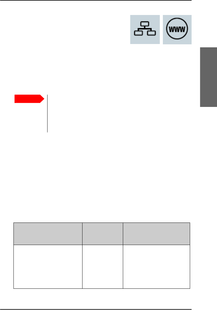
Congratulations on the purchase of your AVIATOR 700 system. It provides
simultaneous high-speed data and voice communication via satellite
through Inmarsat’s SwiftBroadband and Classic Aero services.
See the table below to see the cabin applications that are available.
For instructions how to install and set up the system see the Installation
and Maintenance Manual.
In this chapter
In this chapter you can read about:
•System description
•Aero services — background information
Telephone
(secure)
Internet
E-mail
Wireless
access
point
Built-in
router
Messaging
service
ISDN Fax

Chapter 1: Introduction
2System description
System description
The AVIATOR 700 is a unique multi-channel solution. It combines global
voice, fax and data capabilities of the Inmarsat Classic Aero,
SwiftBroadband and Swift64 service.
These service classes are available on two satellite types: the I4 and I3
satellites. The AVIATOR 700 system supports both types and manages
automatic satellite hand-over between the satellites. This means 100%
worldwide coverage for data and phone services.
For detailed information on services and coverage maps see Aero services
— background information on page 15.
Note
The Classic Aero services are available on both I3 and I4 satellites,
while data services using SwiftBroadband are available exclusively
on I4 satellites. The AVIATOR 700 system uses Swift Broadband
for data services whenever possible. Swift64 is used as a fallback
solution for areas where SwiftBroadband is not available.
Chapter 1: Introduction
System description 3
1111
Introduction
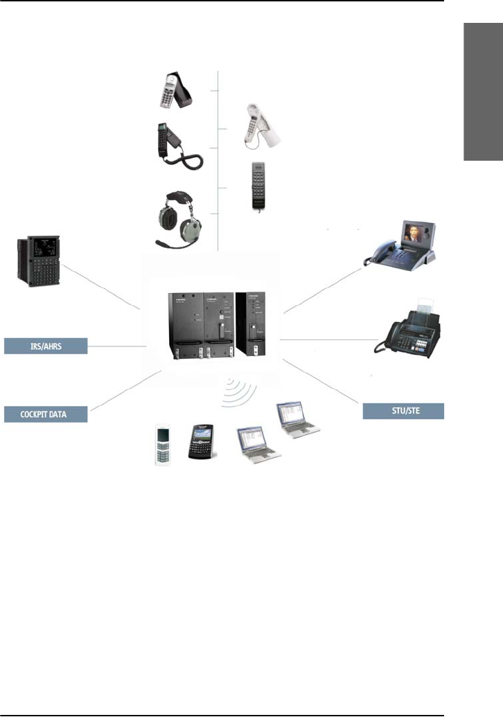
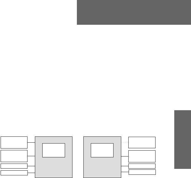
AVIATOR 700 system
PC #1
PC #2
Sigma7
2.4GHz
Full Feature
AFIS/ACARS, CMU
SwiftBroadband Data
LAN/WLAN
Secure Communication
Fax
Videophone
Auxiliary
Handset
MCDU
Handset
Cockpit
Headset
Cordless
Handset
Handset
Smart Phone
SwiftBroadband
Unit (SBU)
Satellite Data
Unit (SDU)
AVIATOR Wireless
Handset

Chapter 1: Introduction
4System description
AVIATOR 700 Features
The AVIATOR 700 system has the following features:
Cockpit audio dialing from MCDU
Cockpit data channel
Interface to ACARS, AFIS and CMU
Data rates up to 432 kbps
VoIP connectivity
Wired and wireless web browsing and corporate VPN access
Wireless use of PDA and Smart Phones
Low cost and high quality voice service
Built-in router for intelligent connectivity support and multiple user
support
Built-in Ethernet switch for supporting multiple wired lap tops
Built-in wireless LAN for supporting multiple wireless devices
Built-in Multi-voice option, up to 1 + 8 concurrent calls
2 built-in PBX for supporting multiple handsets
ISDN connectivity
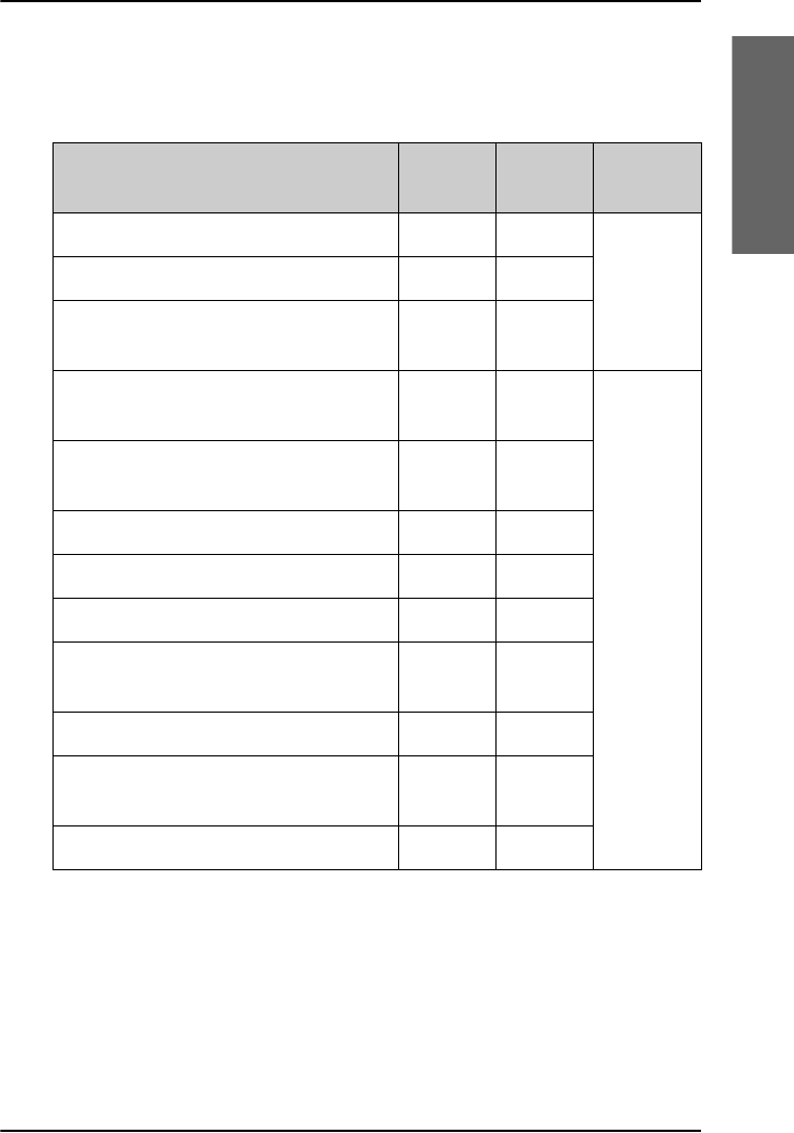
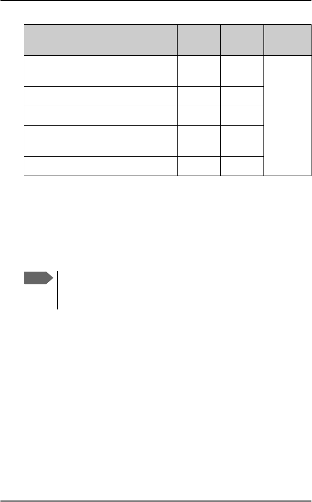
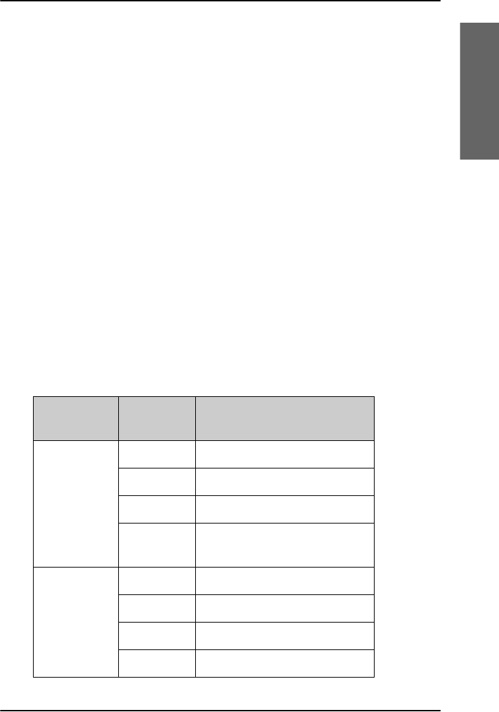
AVIATOR 700 Services
The following table gives an overview of the services available for Inmarsat
services Classic Aero, SwiftBroadband and Swift64.
Typically the system will log on to an I4 satellite where Classic Aero and
SwiftBroadband are available. SwiftBroadband handles all Swift64 services
and more.
Note
The devices in the cabin must be connected to the correct unit,
the Satellite Data Unit (SDU) or the SwiftBroadband Unit (SBU), to
support the individual services. See AVIATOR 700 Interfaces on
page 6.
Chapter 1: Introduction
System description 5
1111
Introduction
For background information on these services, see Background
information, SwiftBroadband services on page 19 and Background
information, Classic Aero and Swift64 services on page 21.
Services I4
satellite
I3
satellite
Inmarsat
service
Voice service Classic
Aero (H+)
2.4 kbps modem/fax
Low speed data (600 or 1200 bps) for
CMU, AFIS and ACARS
IP background service (up to
432 kbps)
Swift
Broad-
band
(SBB)
IP streaming service
(8/16/32/64/128 kbps/X-Stream)
Standard voice (AMBE call)
ISDN UDI 64 kbps
ISDN RDI 56 kbps
High quality audio service (3.1 kHz
(14.4 kbps) for modems, G3 fax etc.)
High-quality voice
Built-in router option with DHCP and
Network Address Translation (NAT)
Built-in wireless option
Chapter 1: Introduction
6System description
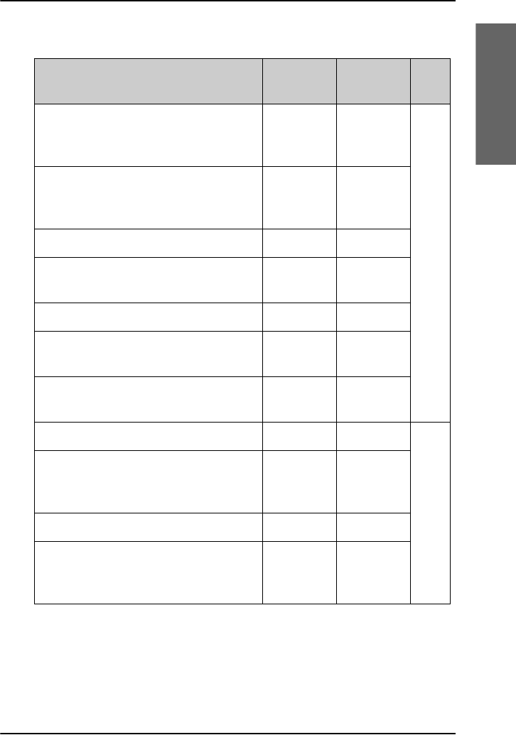
AVIATOR 700 Interfaces
The following table shows the interfaces of the AVIATOR 700 system.
Check with your system responsible for interfaces available in your aircraft.
IP/MPDS background service (up to
64 kbps)
Swift64
(SW64,
HSD)
ISDN UDI 64 kbps
ISDN RDIa 56 kbps
High quality audio service (3.1 kHz
(14.4 kbps) for modems, G3 fax etc.)
High-quality voice (speech)
a. Check with your service provider that the RDI service is available on the
Ground Infrastructure network.
Services I4
satellite
I3
satellite
Inmarsat
service
Note
The devices in the cabin must be connected to the correct unit,
the Satellite Data Unit (SDU) or the SwiftBroadband Unit (SBU), to
support the individual services.
Chapter 1: Introduction
System description 7
1111
Introduction
Interfaces I4
satellite
I3
satellite Via
Full feature handset (4-wire) for voice
service (low cost) or 3.1 kHz high
quality audio service
44SDU
Telephone handsets (2-wire) for voice
service (low cost) or 3.1 kHz high
quality audio service
22
MCDU (Cockpit) 2 2
ARINC 429 (Low speed data 1.2 kbps
for AFIS, ACARS, CMU) (Cockpit)
11
ISDN — 1
Ethernet interfaces for PC etc. (MPDS
via PPPoE) and external router
—1
RS-422 / RS-232 for MPDS via PPP,
UDI and RDIa
a. Check with your service provider that the RDI service is available on the
Ground Infrastructure network.
—1
Ethernet interfaces for PCs etc. 6 — SBU
Built-in wireless access point for
background data and streaming
services
1—
ISDN 1 —
Telephone handsets (2-wire) for voice
service (low cost) or 3.1 kHz high
quality audio service
2—
Chapter 1: Introduction
8System description
Non-Safety interfaces (Level E)
The following interfaces are strictly for non-safety usage:
•Cockpit audio
• ACARS/AFIS/CMU (information and management systems)
• MCDU (Multifunction Control and Display Unit)
Safety interfaces (Level D)
The following interfaces are approved for safety usage:
•Cockpit audio
• ACARS/AFIS/CMU (information and management systems)
• MCDU (Multifunction Control and Display Unit)
Built-in router and Wireless options
The SwiftBroadband Unit of the AVIATOR 700
system offers a built-in router as an option. With
this option you can connect multiple computers,
and several applications can use the system
simultaneously. The system also offers a built-in Wireless option for
wireless communication devices using a WLAN antenna approved for
aeronautical use.
These options are enabled in the AVIATOR 700 by a FLEX key entered
during system configuration, typically at Thrane & Thrane. If not, you can
upgrade your system at a later stage. For upgrade instructions see the
AVIATOR 700 Installation and Maintenance Manual containing detailed
information needed to install and configure the AVIATOR 700 system in
the aircraft..

Chapter 1: Introduction
System description 9
1111
Introduction
PBX telephone exchanges
The AVIATOR 700 system has two built-in independent PBX units:
• PBX in the Satellite Data Unit (SDU)
• PBX in the SwiftBroadband Unit (SBU)
See the overview in AVIATOR 700 Interfaces on page 6 for information on
which types and how many phones can be connected to each PBX. You can
route calls to handsets connected to the same PBX (SDU or SBU).
You can also connect the AVIATOR Wireless Handset.
If you have an IP phone or Smart Phone that has a SIP client, you can use
the integrated SIP server of the SBU. For instructions see To set up a SIP-
enabled wireless IP handset (SBU) on page 81.
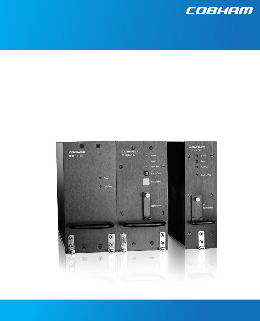
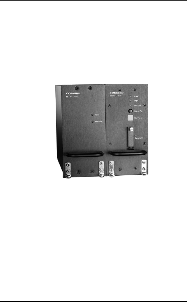
AVIATOR 700 system parts
The AVIATOR 700 system comprises the following parts:
•TT-5035A Satellite Data Unit (SDU) and TT-5014A High Power
Amplifier (HPA)
•TT-5040A SwiftBroadband Unit (SBU)
•Handsets
•Multifunction Control and Display Unit (MCDU) (optional)
•Web interface for SBU control
Note
Call routing between the two PBX units is not supported.
The devices in the cabin must be connected to the correct unit,
the Satellite Data Unit (SDU) or the SwiftBroadband Unit (SBU), to
support the individual services.
A call incoming on the SDU can be routed to a handset marked
SDU, a call incoming on the SBU can be routed to a handset
marked SBU.
Chapter 1: Introduction
10 System description
TT-5035A Satellite Data Unit (SDU) and TT-5014A High Power
Amplifier (HPA)
The SDU is the controlling unit of the satcom system. A Configuration
Module (CM) and all the interfaces, except for the maintenance port, are
located on the rear of this unit.
The High Power Amplifier (HPA) connects to the satcom antenna and
amplifies the transmission signals of all channels simultaneously.
SDU
HPA
Chapter 1: Introduction
System description 11
1111
Introduction
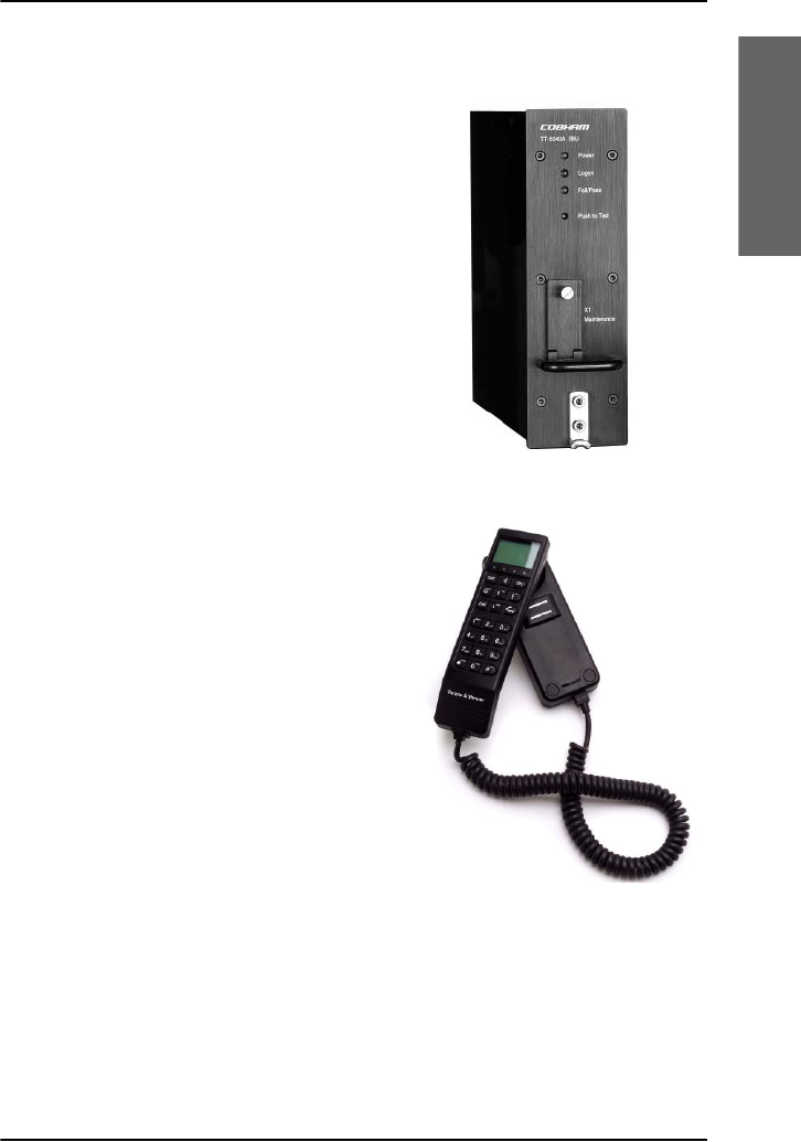
TT-5040A SwiftBroadband Unit (SBU)
The SwiftBroadband Unit (SBU) provides
access to the SwiftBroadband services. A
Configuration Module (CM) and all the
interfaces, except for the maintenance
port, are located on the rear of this unit.
Handsets
TT-5620A Full Feature handset and
TT-5622A Full Feature cradle
The Full Feature handset is used to make
and receive calls and to control, view
status information and configuration data
of parts of the AVIATOR 700 system,
including the SDU.
See Operate the Full Feature handset on
page 62 for a description of keys, LEDs
and display of the Full Feature handset
and How to make calls from the Full
Feature handset on page 71how to make
calls.
Chapter 1: Introduction
12 System description
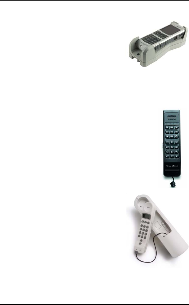
AVIATOR Wireless Handset and Cradle
The AVIATOR Wireless Handset is used to
make phone calls over an IP based network.
The handset connects to a wireless access
point using a Wireless Local Area Network
(WLAN).
See the AVIATOR Wireless Handset and
Cradle, User Manual for a description of the
keys and LEDs of this handset and how to
make calls.
TT-5621B Auxiliary handset and TT-5622B
Auxiliary cradle
The Auxiliary handset is used to receive and to make
calls.
See Operate the Auxiliary handset on page 73 for a
description of the keys and LEDs of the Auxiliary
handset and how to make calls.
Sigma7 handset and cradle
The Sigma7 handset is used to receive and to
make calls.
See How to make a call with the Sigma7
handset on page 79 for a description of how to
use the Sigma7 handset and how to make calls.
Chapter 1: Introduction
System description 13
1111
Introduction
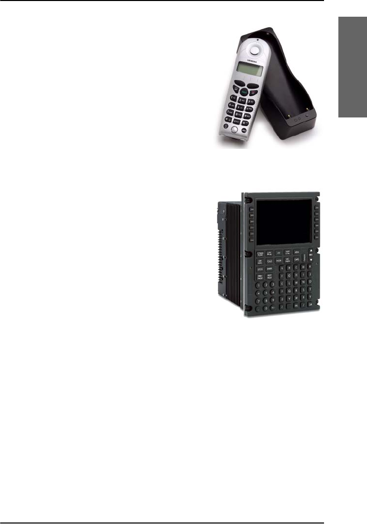
2.4GHz Cordless handset
The 2.4GHz Cordless handset system is used
to receive and to make calls.
See How to make a call with the 2.4GHz
Cordless handset on page 80 for a
description of how to use the 2.4GHz
Cordless handset and how to make calls.
Multifunction Control and Display Unit (MCDU) (optional)
An MCDU can be used to make and receive
calls and to access the AVIATOR 700 menu
system for control and configuration of the
satcom system from the cockpit. A subset of
the MCDU menus and functions are identical
to those of the Full Feature handsets.
With the cockpit audio interface, which
connects to the pilot headset via the cockpit
Audio Management System, the pilot can
make calls from the cockpit without using a
handset.
See Use the MCDU on page 83 for a
description of how to use the MCDU.
(Example)
Chapter 1: Introduction
14 System description
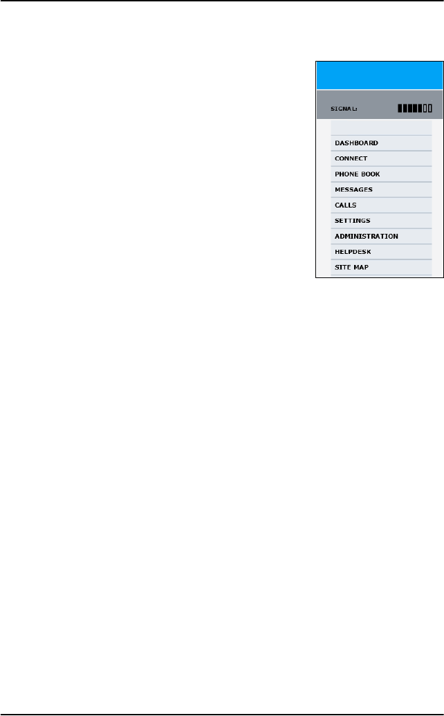
Web interface for SBU control
Use the built-in web interface of the
SwiftBroadband Unit (SBU) to access the system
settings. The web interface is accessed from a
computer connected to one of the LAN
connectors or using the WLAN interface of the
SBU. The web interface is shown in an Internet
browser. No additional installation of software is
needed.
See Introduction to the SBU web interface on
page 164 for a description of how to use the web
interface.
Chapter 1: Introduction
Aero services — background information 15
1111
Introduction
Aero services — background information
Call and data services
The geostationary satellites are your connection to the Internet and
telephone networks. They are situated above the equator. Geostationary
means that the satellites are stationary in relation to Earth, i.e. they rotate at
a speed that matches the rotation speed of the Earth. The satellites are run
and managed by Inmarsat. Inmarsat is the leading provider of global mobile
communications services. Inmarsat keeps track of which units are logged
on to the system, assigns a free channel and manages the data when a
network connection is established or a call is made.
With the AVIATOR 700 system you can use the services SwiftBroadband,
Classic Aero and Swift64. They are accessible worldwide, except the
extreme polar regions. They are represented on the following satellite
types:
•SwiftBroadband: Four I4 satellites
•Classic Aero: Four I4 satellites and four I3 satellites
•Swift64: Four I3 satellites
Satellite
type
Short
name Full name
I4 AMER Americas
MEAS Middle East and Asia
APAC Asia Pacific
EMEA
(Alphasat)
Alphasat (covers Europe,
Middle East and Africa)
I3 AORE Atlantic Ocean Region East
POR Pacific Ocean Region
IOR Indian Ocean Region
AORW Atlantic Ocean Region West

Chapter 1: Introduction
16 Aero services — background information
Each satellite covers a certain area (footprint) and supports a number of
powerful spot-beams making the service available virtually anywhere on
Earth between approximately 70°N and 70°S.
For coverage maps of the satellites see Satellite coverage maps on
page 17.
For uses of these services see AVIATOR 700 Services on page 4.
SwiftBroadband
The Aero SwiftBroadband services are available on four I4 satellites. Each of
these covers a certain area, this is also called a footprint, supporting a
number of powerful narrow-spot-beams making the SwiftBroadband
service available virtually anywhere on the earth.
Classic Aero
The Inmarsat Classic Aero (also called H+) services are available on four I3
satellites and four I4 satellites.
Swift64
The Inmarsat Swift64 (also called High Speed Data or HSD) services are
available on four I3 satellites. This service is used as a fallback solution
when the primary data service, SwiftBroadband, is not available.
Note
Some of the services are available on the interfaces of the SDU,
others on the SBU. See AVIATOR 700 Interfaces on page 6 and
check your cabin installation for interfaces available in your
installation.
Note
The ISDN (Integrated Services Digital Network) and MPDS (Mobile
Packet Data Service) services are only available when the aircraft
is positioned inside an area with Spot Beam coverage.
Chapter 1: Introduction
Aero services — background information 17
1111
Introduction
Satellite coverage maps
The AVIATOR 700 system is typically configured to automatic logon to the
satellite services after power up. The system supports automatic satellite
hand-over when the aircraft moves out of the coverage area for the current
satellite, ensuring permanent coverage by either I4 or I3 satellites. In areas
with no I4 satellite coverage, the system will fall back to an I3 satellite.
When the system moves back into I4 coverage, the hand over to an I4
satellite takes place as soon as there are no active Classic Aero or Swift64
calls.
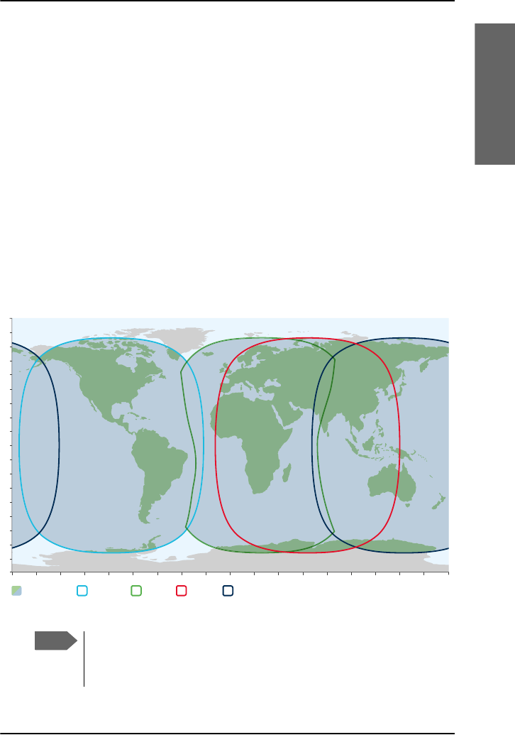
The following figure shows coverage of SwiftBroadband and Classic Aero
services on I4 satellites.
Inmarsat’s I4 satellite coverage (AMER, MEAS, APAC,
EMEA/Alphasat)
0°
10°
20°
30°
40°
50°
60°
70°
80°
90°
10°
20°
30°
40°
50°
60°
70°
80°
90°
0°20°40°60°80°100°120°140°160°180° 20° 40° 60° 80° 100° 120° 140° 160° 180°
Combined I-4 and
Alphasat coverage
I-4 Asia-PacificI-4 Americas Alphasat I-4 MEAS This map depicts Inmarsat’s expectations of coverage following the commercial
introduction of Inmarsat’s fourth L-band region, scheduled for the end of 2015. It does not
represent a guarantee of service. The availability of service at the edge of coverage areas
pXFWXDWHVGHSHQGLQJRQYDULRXVFRQGLWLRQV6ZLIW%URDGEDQGFRYHUDJH'HFHPEHU
Note
The map above shows Inmarsat’s SwiftBroadband services
coverage. The map does not represent a guarantee of service. The
availability of service at the edge of coverage areas may fluctuate.
Chapter 1: Introduction
18 Aero services — background information
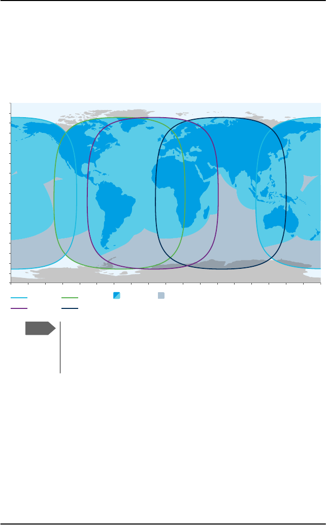
The following figure shows coverage for Classic Aero and Swift64 services
on I3 satellites.
Swift64 and Classic aeronautical services coverage (IOR, POR,
AORE, AORW)
Earth Stations for Classic Aero services and Swift64
The gateway between the public network and the satellites is operated by a
Land Earth Station (LES) for the Swift64 data communication or Ground
Earth Station (GES) for the global voice, fax and low-speed data capabilities.
The LESs and GESs are run by different operators around the world.
This map depicts Inmarsat’s expectations of coverage, but does
not represent a guarantee of service. The availability of service
DWWKHHGJHRIFRYHUDJHDUHDVpXFWXDWHVGHSHQGLQJRQYDULRXV
conditions. Classic Aero and Swift 64 coverage December 2015.
0°
10°
20°
30°
40°
50°
60°
70°
80°
90°
10°
20°
30°
40°
50°
60°
70°
80°
90°
0°20°40°60°80°100°120°140°160°180° 20° 40° 60° 80° 100° 120° 140° 160° 180°
Atlantic Ocean Region-East
Aero H services are provided in the
full footprint of the global beams
Swift 64, Aero H+,
Aero I coverage
Pacific Ocean Region Atlantic Ocean Region-West
Indian Ocean Region
Note
The map above shows Inmarsat’s Swift64 and Classic Aero
services coverage. The map does not represent a guarantee of
service. The availability of service at the edge of coverage areas
may fluctuate.
Chapter 1: Introduction
Aero services — background information 19
1111
Introduction
Background information, SwiftBroadband services
SwiftBroadband offers the basic services:
• Symmetric ‘always on’ data connection, packet switched (PS)
• Voice and ISDN (voice and data) service, circuit switched (CS)
• Short Messaging Service (SMS) in the AVIATOR 700 system
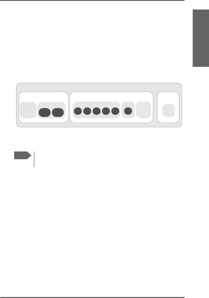
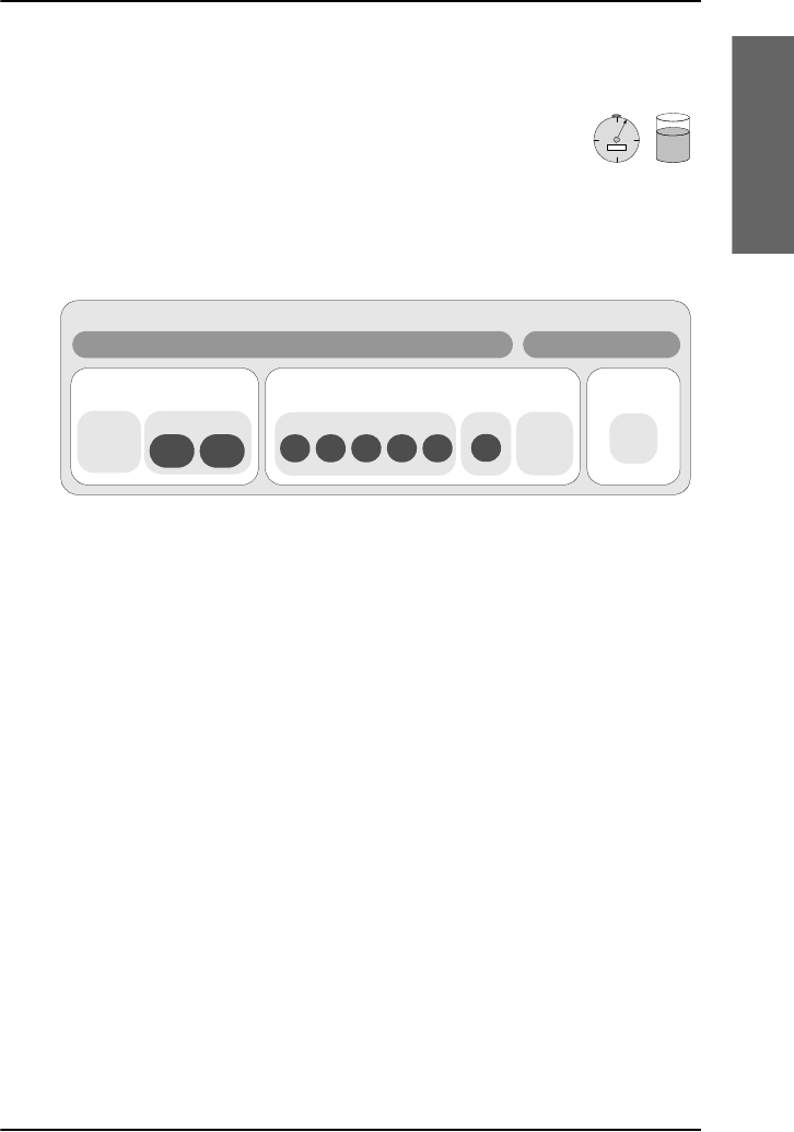
The following figure shows how the services are accommodated in a
SwiftBroadband channel.
With SwiftBroadband you can combine multiple packet-switched services
with one circuit-switched service active at the same time
Circuit switched (dialed) service
SwiftBroadband also provides high-quality telephone services (including
secure mode). The following types of circuit switched connection are
available:
•Standard voice. A low-cost connection for voice only. The voice signal
is compressed to 4.0 kbps, which reduces the bandwidth use and
consequently the cost. This is also called AMBE.
•3.1 kHz audio. A high quality connection which can be used for
Premium Voice, G3 fax or analog modems. The signal is uncompressed
3.1 kHz audio, which allows for optimum voice quality.
•ISDN. A high quality connection which can be used for voice (3.1 kHz
Audio), G4 fax or 64 kbps UDI/RDI data.
Note
The SwiftBroadband system only supports one circuit-switched
call at a time per AVIATOR 700 system.
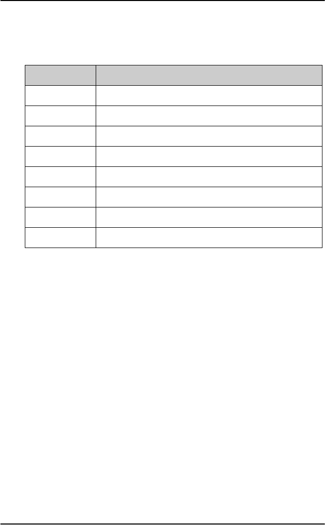
Applications supported by the SwiftBroadband service
Circuit switched service
Standard
Voice
4 kbps
Packet switched service
64 kbps
3.1 kHz
Audio ISDN
Messaging
service
SMS
service
Standard
IP
(Internet,
e-mail,
FTP.)
Streaming IP (video, audio)
128
kbps
64
kbps
32
kbps
16
kbps
8
kbps
X-Stream
512
kbps
Chapter 1: Introduction
20 Aero services — background information
Packet switched service
The IP-based packet-switched service provides a data rate of up to 432
kbps. The packet switched service offers two types of connection: In
Standard IP mode, the service is shared among users of the system,
providing a 'best effort' service. This type of connection is ideal for e-mail,
file transfer, and Internet and intranet access. The user pays for the data
sent and received. This type of connection is also called Background IP.
You can also use the SwiftBroadband service at a pre-determined quality of
service, i.e. with a specified streaming data rate. This service is called
Streaming IP. This type of connection is ideal for time critical applications
like live video over IP. The user pays for the duration of the connection (per
minute charge)
Messaging service
SwiftBroadband provides a generic messaging service for
sending and receiving messages to and from the AVIATOR 700
system.
Supplementary telephone services
The following supplementary telephone services are available:
• Call hold
• Call waiting
• Call forwarding
• Conference call (Multi-party calls)
•Voice mail
• Call barring
These services are typically set up during the initial configuration of the
system. For further details on Call forwarding see To forward a call (SBU) on
page 58, the other supplementary telephone services are described in detail
in the AVIATOR 700 Installation and maintenance manual.
Note
The SBU of the AVIATOR 700 supports up to 11 concurrent
packet-switched connections at a time. For use of packet
switched services also see AVIATOR 700 Services on page 4.
Chapter 1: Introduction
Aero services — background information 21
1111
Introduction
Airtime pricing principles
When using the connections of your system note that the
circuit switched services and streaming classes (packet
switched) are charged by the time the service is being used,
while the standard IP and SMS services (packet switched)
are charged by the volume of data transferred.
The following image shows how the various applications are supported by
the SwiftBroadband service.
For information on service availability see AVIATOR 700 Services on
page 4.
Background information, Classic Aero and Swift64
services
The Classic Aero services have a lower tariff than the Swift64 services,
which are high quality audio or high speed data services and thus require
more bandwidth.
Classic Aero services
The Classic Aero (H+) service supports near terrestrial-quality Voice at
4.8 kbps, over 2 different physical channels in both global- and spot beam.
This means that the user can have 2 voice connections up at all times. This
can be 2 incoming, 2 outgoing or 1 incoming and 1 outgoing connection.
This service is less expensive than an ISDN connection, with only a small
cost in voice-quality.
Besides using the two voice-channels for voice, one or both of the channels
can be used for a modem or fax connection. In both circumstances, the
60
15
30
45
00:10:35
Airtime pricing for SwiftBroadband services
Circuit switched service Packet switched service Messaging
service
SMS
service
Charged by time Charged by volume
Standard
Voice
4 kbps
64 kbps
3.1 kHz
Audio ISDN
Standard
IP
(Internet,
e-mail,
FTP.)
Streaming IP (video, audio)
128
kbps
64
kbps
32
kbps
16
kbps
8
kbps
X-Stream
512
kbps

Chapter 1: Introduction
22 Aero services — background information
maximum bit rate is 2.4 kbps. The fax or modem can be connected to the
2-wire interface. If a fax or modem uses a channel, this channel cannot be
used for voice at the same time.
Classic Aero also provides a low speed packet data mode, which allows
data transfers at up to 1.2 kbps. This service can be used by an AFIS
(Automatic Flight Information Service), ACARS (Aircraft Communication
Addressing & Reporting System) or CMU (Communications Management
Unit) to send data over the satellite link. Note, however, that this service
must not be used as the basis for safety communication.
Swift64 data service
The 64 kbps UDI (Unrestricted Digital Information) service enables bi-
directional transmission of data to and from terrestrial 64 kbps ISDN
networks. The 56 kbps Data service is similarly used to make a connection
to 56 kbps ISDN networks, which are primarily used in North America.
The Speech and 3.1 kHz audio services make it possible to establish high
quality analogue connections with quality equal to terrestrial analogue
connections via digital networks/switches. The Speech service is used for
high quality voice connections, whereas 3.1 kHz audio can be used to
transfer analogue signals between fax machines and modems with an
analogue 2-wire interface. The 3.1 kHz audio service is transparent, and is
suitable for all analogue applications including secure telephones.
The MPDS service is a packet data service where the tariff depends on the
amount of data transmitted. This service is a more cost-effective solution
for web browsing, and other applications where there is no need for
constant transmission of data in both directions. It is also suitable for
applications where a constant connection is required, because the user is
no longer charged the “per minute rate”.

23
Chapter 2
2222
Get started
Get started 2
In this chapter
In this chapter you can read about:
•Logon procedure
•Connect a computer
•Make the first call
•Send a fax
For information on how to install, configure and service the system, see the
AVIATOR 700 Installation and maintenance manual. For more detailed
guidelines on the individual applications see Calls, faxes and SMS on
page 33.
Line of sight
To use the satellite network, the satcom antenna must have free line of
sight to the satellite.
Note
The system cannot logon to the satellite network and go online
when the aircraft is inside a hangar.
Picture: airphototicino

Chapter 2: Get started
24
Airtime service provisioning
To be able to establish a data connection or make a call the
satcom system must be activated or commissioned by a service
provider. This is taken care of during installation and
configuration of the satcom system. The service provider
provides the telephony and data services and invoices you for
the services used. For information on service providers go to
Inmarsat’s web site, Partner search
(http://www.inmarsat.com/partners/search-for-partner/). The service
provider also handles activation, commissioning, billing and technical
support that is related to the communication network.
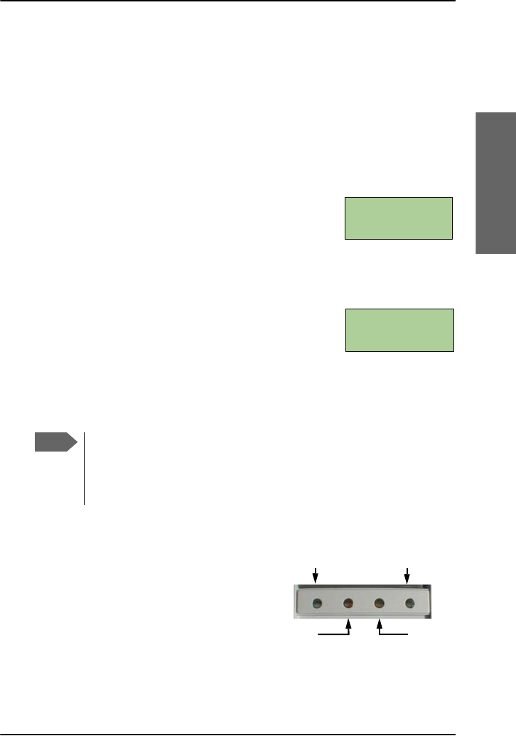
The satcom system is operational and ready to use when the aircraft is
powered up and the aircraft’s navigational system has finished its
initialization. Check whether your aircraft is equipped with a signal saying
that the satcom system is ready for use before you start your application.
Default settings
The telephone and ISDN lines are available as soon as the system has
logged on to the satellite network. Check whether your aircraft is equipped
with a signal saying that the satcom system is ready for use.
Internet, e-mail and other IP services are available as plug-and-play, no
further configuration is needed. The system automatically starts the
standard background data connection when a PC, Smart Phone or other
device is connected.
Important
With the plug-and-play functionality a computer
automatically establishes a connection to the
Internet and starts transferring data as soon as you
start using the Internet, e-mail or other IP services.
To avoid unintended use of bandwidth, e.g. automatic
software updates, see Unintended use of bandwidth on
page 107 for information how to set up your computer.
Chapter 2: Get started
Logon procedure 25
2222
Get started
Logon procedure
You can logon to satcom services using one of the following procedures:
•Logon procedure with the Full Feature handset
•Logon procedure with the MCDU
Logon procedure with the Full Feature handset
After power up the display and all LEDs on the Full
Feature handset will light up for a few seconds, the
SDU boots and makes a self test. The system is
typically configured to log on automatically to the satellite services, no
further action is required. When the display shows Ready all services are
logged on and you can start using the system.
In most cases the system logs to an I4 satellite. If
there is no I4 coverage, the system logs on to an I3
satellite. Then the SwiftBroadband services are not
available. The display will show: H+ (Classic Aero) and Swift64 are logged on
(ok) and SBB (SwiftBroadband) is not available (0/1). Then you can make
calls using the Full Feature handset and the SDU using the service H+
(Classic Aero) and you can use SW64 data.
LEDs on Full Feature handset
The Classic Aero LED and the Swift64
LED indicate that these services are
logged on. This handset has no LED to
indicate that the SwiftBroadband
service is logged on. The
SwiftBroadband service is logged on
when the display shows Ready and the Swift64 LED is not lit.
Note
If the system does not log on automatically, the system may be
set to manual logon. In this case you have to log on using the
Logon menu. For further information, see To log on manually on
page 125.
Ready
AMER AM #x
H+ SBB SW64
ok 0/1 ok
Classic Aero (H+)Swift64 (HSD)
Alarm Ringing
Chapter 2: Get started
26 Logon procedure
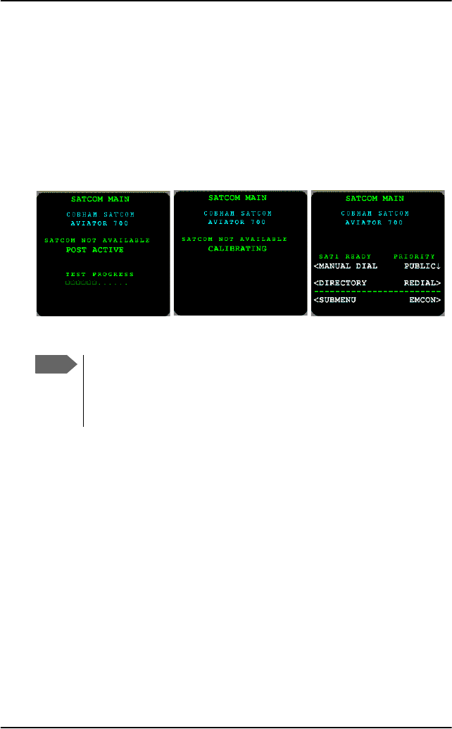
Logon procedure with the MCDU
After power up the system is typically configured to log on automatically to
the satellite services. No further action is required to start up the AVIATOR
700 system. You can follow the logon procedure by selecting the SATCOM
subsystem from the MCDU menu when the SATCOM subsystem becomes
available. Below is an example of a display read-out while the SDU is
booting. The screen shows the progress of the Power On Self Test (left) and
the screen after a successful logon procedure (right).
For further information on logon settings, see LOGON menu on page 153.
Note
If the system does not log on automatically, the system may be
set to manual logon. In this case you have to log on using the
Logon menu. For further information, see LOGON menu on
page 153.
Chapter 2: Get started
Connect a computer 27
2222
Get started
Connect a computer
PC setup — before you start
For the LAN or WLAN interface to work without any further setup, the
connected computer or IP device must be set up to obtain an IP address
and a DNS server address automatically. This is usually the case for most
PCs. If you are in doubt you can check your PC, see the step-by-step
procedure how to do this in IP address and DNS server address setup on
page 166.
Internet, e-mail, etc.
With SwiftBroadband the cabin applications e-mail, Internet and intranet
access, VPN, etc. are available. The connection type recommended for
these applications is the Standard data connection, which is also the default
setting. For background information on the Standard data connection see
Packet switched service on page 20.
Depending on how your system was set up initially there are two scenarios
that may be applicable when you use a data connection to access the
Internet, e-mail etc.:
Important
To avoid unintended use of bandwidth, e.g. automatic
software updates, see Unintended use of bandwidth on
page 107 for information how to set up your computer. It is
recommended to disable the feature for automatic PC
software update in your computer.
Standard data
connection Benefits Drawback
Automatic start
(system default)
Plug-and-play Risk of unintended use of
costly airtime, e.g.
Windows update
downloads, frequent
check for new mail etc.

Chapter 2: Get started
28 Connect a computer
Check with your system responsible whether your system is set up to
automatic activation of a standard data connection (plug-and-play).
To access the Internet or use your e-mail program do as follows:
1. Switch on your PC or Smart Phone.
2. For LAN: Connect your LAN cable (standard Ethernet) between the
network connector on your computer and one of the LAN connectors
installed in the aircraft.
For WLAN: Check that the WLAN icon in the status bar of your
operating system indicates that the WLAN connection has been
established.
3. Start your application, e.g. Internet browser or e-mail program.
If you cannot establish a connection, the automatic activation of a
standard data connection may be disabled in your system. Then you
can start a connection manually, you do this in the built-in web
interface. To learn more about the web interface see Use the SBU web
interface on page 164.
How to establish a connection manually see Start or stop a Standard
connection on page 110 or Start or stop a Streaming connection on
page 111 for detailed instructions.
If you want to change the start-up mode of the standard data
connection contact your system administrator to change the setting in
your network user group for Automatic activation to Enabled or
Disabled. This is described in detail in the AVIATOR 700 Installation
and maintenance manual.
Manual start from the
web interface
(This must be configured
during initial
configuration.)
Efficient
bandwidth
usage
You must start the web
interface at
http://192.168.0.1 and
click once to start a
connection.
Standard data
connection Benefits Drawback

Chapter 2: Get started
Make the first call 29
2222
Get started
Make the first call
The following sections provide a short guide to making calls. For more
detailed information, see How to make calls from the Full Feature handset
on page 71 or How to make calls from the Auxiliary Handset on page 76.
If you want to use a SIP-enabled IP handset to make a call see Use a SIP-
enabled IP handset (SBU) on page 81.
Make a call (air to ground)
To make a call from a phone or handset, press:
00 <country code> <phone number> followed by # or off-hook key.
Example: To call Cobham SATCOM VA that has the country code 1 and
the phone number 7574639557 press
00 1 7574639557 #
Call a handset in the aircraft (ground to air)
Mobile numbers for SwiftBroadband
You find the voice numbers in the documentation in the aircraft cabin or
from your service provider. They may also figure on the quick guide. Make
sure you have the international dialling code for the country you want to
call from.
To make a call to a phone connected to the SBU (ground to air), dial:
+ <Mobile number>
•+ is the prefix used in front of the country code for international calls.
The Prefix depends on from which country you make the call. It is 011 if
you call from the USA.
•Mobile number for handsets connected to the SBU: This is the
mobile number of the system you are calling. The first part of the
number is always 870, which is the “country code” for the BGAN system.

Chapter 2: Get started
30 Make the first call
Example: If you are calling from the USA and the mobile number for
standard voice is 870772420567 on your system, and you
want to make a call to the system, dial 011 870 772420567.
Voice mail for SwiftBroadband
If a call to a handset marked AVIATOR 700 is not answered the caller can
leave a voice mail message with Inmarsat’s voice mail service. Then an SMS
is sent to the messaging system of the SBU to alert you that there is a voice
mail message. For further details see To receive a voice mail message
(SBU) on page 52.
Note
There are two Voice numbers, one for 3.1 kHz Audio and one for
Standard Voice.
Note
For fax installations: If you have connected a fax, make sure
that the incoming call type on that 2-wire interface is set to 3.1
kHz Audio. This is to avoid that the fax rings and answers an
incoming Standard call. This is usually taken care of during initial
configuration of the system. See the AVIATOR 700 installation
and maintenance manual for further information on connecting a
fax to the SBU.

Chapter 2: Get started
Make the first call 31
2222
Get started
Mobile number for Classic Aero services
To make a call to a phone connected to the system do as follows:
Dial + <Mobile number>
To make a phone call to a handset in the aircraft you can proceed in two
ways:
To call using DDI numbers see To call ground to air using the DDI
numbers on page 38, for more information about SWIFT64 number see
Swift64 numbering rules on page 39.
Classic
Aero Details Dialling example
Direct
phone
number
A direct phone number to call a
handset in the aircraft directly.
When using this number a
dialing prefix is not required.
Check the documentation from
your service provider whether
this service is supported.
See the documentation
from your service
provider.
Numbering
rules for
AESID
The international prefix used to
call from the ground is +870
+ is the prefix used in front of
the country code for
international calls. The Prefix
depends on from which country
you make the call. It is 011 if
you call from the USA.
Note: In some countries or
networks the access to +870
maybe restricted and requires
an account to be set with the
local service provider.
Dial: +870 5 <AESID>
If you are calling from
the USA and the ICAO
address is 01234567
dial: 011 870 5
01234567

Chapter 2: Get started
32 Send a fax
Send a fax
Send a fax via SBU
To send a fax from the terminal (SBU), use the prefix 00, followed by the
called fax number including the country code, followed by #.
Example: To send a fax to Cobham SATCOM VA (country code 1) over
SwiftBroadband, press the following keys on the fax:
00 1 757 463 9557 #
Send a fax via SDU
To send a fax from the terminal (SDU), use the prefix 01 for fax, followed
by the called fax number including the country code, followed by #.
Example: To send a fax to Cobham SATCOM VA (country code 1) over
Classic Aero press the following keys on the fax:
01 1 757 463 9557 #
You can also send a fax over Swift64, for instructions see To send a fax
message (air to ground) (SDU) on page 44.
To power off the satcom system
The satcom system is automatically powered off along with the aircraft.
Some types of aircraft are equipped with a “SatCom on/off” button, which
can be used to power off the satcom system while the aircraft is powered.
Important
Before sending or receiving fax messages, make
sure both fax units are in “Overseas” mode.
33
Chapter 3
3333
Calls, faxes and SMS
Calls, faxes and SMS 3
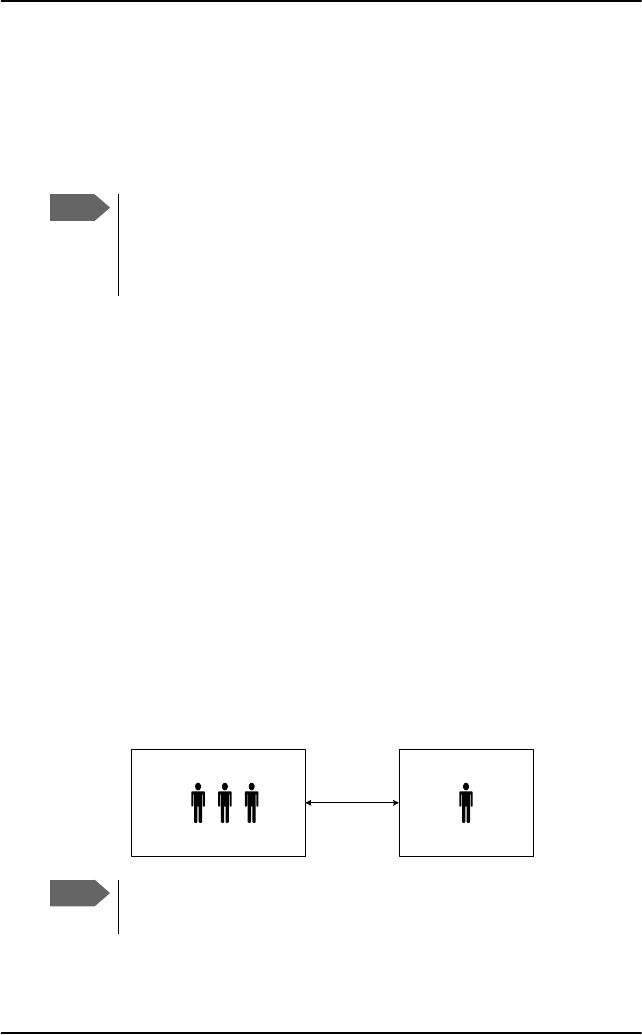
Introduction
The AVIATOR 700 system has two PBXs. Study the following chapters
thoroughly, because you need to know to which units — SDU or SBU —
the phone or fax is connected, to be able to call or use the fax successfully.
For some functions you also have to know whether you use the Full Feature
handset or a POTS (2-wire) handset like the Auxiliary handset. The following
illustration shows schematically which phone and fax connections are
available.
In this chapter
In this chapter you can read about:
•Use a phone or fax machine (SDU)
•Use a phone or fax machine (SBU)
•Operate the handsets
•Use the MCDU
•SMS service
SDU
PBX
SBU
PBX
Full Feature
handset
(up to 4)
Auxiliary or other
POTS handset
(up to 2)
Fax
Auxiliary or other
POTS handset
(up to 2)
Fax
ISDN ISDN
AVIATOR
Wireless Handset
(several)

Chapter 3: Calls, faxes and SMS
34 Use a phone or fax machine (SDU)
Use a phone or fax machine
(SDU)
Available interfaces (SDU)
Several types of voice equipment connect to the SDU:
Standard analog phone or G3 fax machine: The SDU has two phone
interfaces for connecting standard analog phones or fax machines.
ISDN phone or G4 fax machine: The SDU has one ISDN interface for
connecting an ISDN phone, a modem or a fax machine.
Full-feature handset: the SDU has four phone interfaces for connecting
Full Feature handsets.
Check the cabin installation to locate the SDU connectors for telephones
and fax machine.
Select a call type (SDU)
This is typically set up during initial configuration of the system.
The phone connection can use one of the following call types:
•H+ Voice: Voice connection compressed to 4.8 kbps,
•3.1 kHz Audio: High quality connection used for Premium Voice, G.3
fax or analog modem,
•UDI or RDI (only on ISDN interface): used for G4 fax or data
The default setting for an AVIATOR 700 system is standard voice.
In the Aero-SDU Configuration Program which is used during the
installation of the system you can set up which type of connection should
be preferred to use when you make or receive a call from the telephone
interfaces.
Note
Modem or fax: When connecting a fax or a modem to the
Phone/Fax interface you must use 3.1 kHz Audio.

Chapter 3: Calls, faxes and SMS
Use a phone or fax machine (SDU) 35
3333
Calls, faxes and SMS
Example: If you always have a fax connected to the same Phone/Fax
interface you can set this interface to 3.1 kHz Audio only. This
will mean that if an incoming Standard Voice call is received,
this Phone/Fax interface will not ring. For details how to set up
the interfaces see the AVIATOR 700 Installation and
maintenance manual.
When connecting a G4 fax or a modem to the ISDN interface in the
AVIATOR 700 system you must use UDI.
To select the default outgoing call type (SDU)
This is typically set up during initial configuration of the system.
You can set the default outgoing call type in the Aero-SDU Configuration
Program. For further information, see the AVIATOR 700 Installation and
maintenance manual and the online help of the Aero-SDU Configuration
Program.
Important
Primary and secondary call types can be configured in the
Aero-SDU Configuration Program. If all channels for the
primary call type are in use, the secondary call type will be
used.

Chapter 3: Calls, faxes and SMS
36 Use a phone or fax machine (SDU)
To override the default outgoing call type (SDU)
To override the default setting for a specific outgoing call, dial the following
prefix before the number you want to call or fax:
• 00: Use default call type
• 01: Use default fax type
• 10: Force the call type to H+ (Classic Aero) (Standard voice)
• 11: Force fax type H+ (Classic Aero)
• 20: Force call type HSD (Swift64) (High-quality voice)
• 21: Force fax type HSD (Swift64)
Example: To call Cobham SATCOM VA, that has the country code 1 and
the phone number 7574639557, forcing the connection to use
Standard Voice, dial
10 1 7574639557 followed by # if calling from an analog or
ISDN phone, or off-hook key if calling from an AVIATOR
Wireless Handset.
Phone numbers for incoming 3.1 kHz Audio and Standard Voice
The phone numbers are listed in the documentation from your service
provider.
For information on how to make a call to the system, see Phone number
for a call (ground to air) (SDU) on page 38.
To select the incoming call type (SDU)
This is set up during initial configuration of the system. For further
information, see the AVIATOR 700 Installation and maintenance manual
and the online help of the Aero-SDU Configuration Program.
Note
This will not change the default call type, only the type used for
this call.
Note
The call type you are using must be selected in the Aero-SDU
Configuration Program.

Chapter 3: Calls, faxes and SMS
Use a phone or fax machine (SDU) 37
3333
Calls, faxes and SMS
Make or receive a phone call (SDU)
Analog phone, ISDN phone or Full Feature handset
There are different methods for activating a call, depending on the type of
phone:
•Analog phone or ISDN phone: Dial the number and press #.
•Full feature handset: Dial the number and press the off-hook key.
To make a call (air to ground) (SDU)
You have the following options for making a call:
•Manual Dial. Dial 00 <country code> <phone number> followed
by # or off-hook key.
Example: To call Cobham SATCOM VA that has the country code 1
and the phone number 7574639557 press 00 1
7574639557 followed by # if calling from an analog or
ISDN phone.
•Full Feature handset: Call a number in the SDU phone book. If
the number you want to call is in the phone book of the SDU, find the
number in the phone book and press # or off-hook key.
Example: To call entry in the SDU phone book with the name Jones, press
CC to enter the phone book, then N. To find an
entry with the name Larsen, press N three times.
For more detailed information about the SDU phone book see
Use the SDU phone book on page 115.
If there was an error establishing the connection, refer to SDU errors on
page 190.
To receive a call (SDU)
By default, all devices connected to the 4-Wire interfaces, 2-Wire interface
and the ISDN interface will ring when one of the mobile numbers is called.
Note, however, that this depends on the call type settings made during
initial configuration of the system. For further information, see the

Chapter 3: Calls, faxes and SMS
38 Use a phone or fax machine (SDU)
AVIATOR 700 Installation and maintenance manual and the online help of
the Aero-SDU Configuration Program.
Phone number for a call (ground to air) (SDU)
For details on how to make a call to a phone connected to the system see
Mobile number for Classic Aero services on page 31.
To call ground to air using the DDI numbers
It is possible to dial a specific terminal in the aircraft, using a specific service
(voice, fax or data).
From a ground phone dial: +870 5 <DDI> <Terminal Number>
DDI (Direct Dial-In)
The DDI number identifies both the terminal on the network and the
service used (Voice, Fax or Data).
Example: The following is an example of a Ground to air call using DDI
numbers:
If the DDI numbers allocated are:
-111112 for voice
-111113 for fax
-111114 for data
-and you are making a call from USA,
the phone number to dial on the ground to call handset #2 is:
011 870 5 111112 02 (011 for prefix to dial out of the USA -
870 international prefix to call from the ground - 5 for H+
service - DDI Voice - Terminal number 2)
Under the same circumstances, the phone number to dial on
the ground to send a fax connected to POTS #5 is:
011 870 5 111113 05 (011 for prefix to dial out of the USA -
870 international prefix to call from the ground - 5 for H+
service - DDI Fax - Terminal number 5)
Note
In the Service Activation Registration Form (SARF), the allocation
of DDI number is optional. Make sure that they are requested
when submitting the SARF.

Chapter 3: Calls, faxes and SMS
Use a phone or fax machine (SDU) 39
3333
Calls, faxes and SMS
Local numbers
• 00: The terminal will behave as if it has received a call using the AES
ID (a broadcast call to all handsets)
• 01: Handset #1 (Full Feature handset)
• 02: Handset #2 (Full Feature handset)
• 03: Handset #3 (Full Feature handset)
• 04: Handset #4 (Full Feature handset)
• 05: POTS #5 (2-wire analog phone)
• 06: POTS #6 (2-wire analog phone)
Swift64 numbering rules
IMN (Inmarsat Mobile Number): To make a ground-to-air call to a
terminal using swift64, the caller can use the IMN numbers as follows:
Dial +870 <IMN number>
An IMN is the network identification for a specific service on a specified
terminal. The service can be ISDN DATA64, ISDN DATA56, SPEECH or
AUDIO3.1.
Example: If the IMN number is 612345678 and you are making the call
from USA, dial 011 870 612345678.
To make local phone calls (SDU)
You can make local phone calls between any of the POTS phones and 4-
wire handset interfaces of the SDU.
To make a local call to a phone connected to the SDU do as follows:
Dial <local number> and press # or the off-hook key.
Important
This feature works with handsets connected to the SDU.
Check whether the handset is marked “SDU”.
Note
The local number is shown in the lower right corner of the display
of the Full Feature handsets.
Chapter 3: Calls, faxes and SMS
40 Use a phone or fax machine (SDU)
Special-purpose and local numbers
The following list shows the allocated special-purpose numbers.
Local number Phones
SS 0 Broadcast call to all phones connected to the SDU
1 4-Wire (Full Feature handset) #1
2 4-Wire (Full Feature handset) #2
3 4-Wire (Full Feature handset) #3
4 4-Wire (Full Feature handset) #4
5 2-Wire handset (Auxiliary or similar) #5
6 2-Wire handset (Auxiliary or similar) #6
10 ISDN

Chapter 3: Calls, faxes and SMS
Use a phone or fax machine (SDU) 41
3333
Calls, faxes and SMS
To hold a call (SDU)
You can put an incoming, outgoing or local call on hold once the
connection is established. To place an active call on hold, press the hold
button on the phone. Once the call is put on hold, a ready tone will sound in
the handset. To reactivate the call, press the hold button a second time.
To place a call on hold using the Auxiliary handset, do as follows:
1. Press F.
2. To reactivate the call, press F.
To place a call on hold with the Full Feature handset, do as follows:
1. Press GT.
2. To reactivate the call, press GT.
To transfer a call (SDU)
An incoming or outgoing call can be transferred from one local phone A to
another local phone B connected to the same SDU.
Use the following procedure to make a call transfer using the Auxiliary
handset:
1. Press F on phone A to put the call on hold.
2. On phone A, dial the desired handset, e.g. K for handset #2. For local
numbers see Special-purpose and local numbers on page 40.
Note
Which key works as a hold button varies from phone to phone.
To find out which button is the hold button on your handset, refer
to the phone’s user manual. On some digital phones, an R button
functions as the hold button (like for the Auxiliary Handset). On
analog phones without a dedicated hold button, a short press on
the hook button functions as a hold button (this is called the flash
button on analog phones).
Note
Only one call can be placed on hold at the same time by a single
phone.
Chapter 3: Calls, faxes and SMS
42 Use a phone or fax machine (SDU)
3. Establish a connection between phone A and B with U.
4. The transfer can then be initiated by either phone:
• Hang up phone A or
• Press S K K K from phone B.
Use the following procedure to make a call transfer using the Full Feature
handset:
1. When a call is already established, place the call on hold with GT.
2. On phone A dial the number of the desired handset, e.g. K for
Handset #2. For local numbers see Special-purpose and local numbers
on page 40.
3. Establish a connection between phone A and B with U or I .
4. The transfer can then be initiated by either phone:
• Hang up phone A or
• Press GS from either handset A or B
To make a conference call (SDU)
It is possible to make conference calls between three or more parties.
Note
To transfer a call from a POTS phone, the procedure is the same as
for the Auxiliary Handset except from the method to put the call
on hold. For information how to put a call on hold from a POTS
phone see To hold a call (SDU) on page 41.
Note
Max. 6 lines can be connected, including handsets on the aircraft
and lines to the ground.
Air
Conference (up to 6)
Conference call (SDU)
Ground
(up to 3)
Phone call
(Classic Aero)

Chapter 3: Calls, faxes and SMS
Use a phone or fax machine (SDU) 43
3333
Calls, faxes and SMS
When a call is already established, do as follows to add additional parties
with an Auxiliary Handset:
1. Press F to put the call on hold.
2. On phone A, dial the desired handset, e.g. K for handset #2, or an
external number. For local numbers see Special-purpose and local
numbers on page 40.
3. Establish connection with U.
4. Join all three calls by pressing S LLL from either phone.
5. To add further parties to the conference all, repeat steps 1 to 5.
6. To leave a conference, press I or put handset back into the cradle.
When a call is already established, do as follows to add additional parties
with the Full Feature Handset:
1. Place the call on hold with GT.
2. Dial the number of the desired handset, e.g. K for Handset #2, or an
external number. For local numbers see Special-purpose and local
numbers on page 40.
3. Establish a connection between phone A and B with U or I .
4. Join all three calls by pressing GU from either handset
5. To add further parties to the conference call, repeat steps 1 to 5.
6. To leave a conference, press I or put handset back into the cradle.
Note
To make conference call from a POTS phone, the procedure is the
same as for the Auxiliary Handset except from the method to put
the call on hold. See To hold a call (SDU) on page 41 for
information about putting calls on hold from a POTS phone.
Note
When the last local phone exits the conference call, the
conference call is terminated though there may still be two or
three incoming/outgoing callers active.

Chapter 3: Calls, faxes and SMS
44 Use a phone or fax machine (SDU)
Send or receive a fax message (SDU)
Delay before time-out
When sending or receiving fax messages over a satellite connection, the fax
units at each end of the transmission line must be capable of handling
longer delays without timing out. Some fax machines have an Overseas
mode, which enables the unit to handle the long delays. Make sure that
your fax machine is set to allow long delays before time-out.
To send a fax message (air to ground) (SDU)
The fax machine must be connected to the Phone/Fax interface or the
ISDN interface of the SDU. For an analog fax machine 3.1 kHz Audio
should be used. For an ISDN G4 fax machine UDI must be used, refer to the
AVIATOR 700 Installation and maintenance manual for details how to
configure the ISDN interface.
To send a fax from the SDU, use the prefix 01 for fax, followed by the
called fax number including the country code, followed by #. For more
information how to override call types see To override the default
outgoing call type (SDU) on page 36.
Example: To send a fax to Cobham SATCOM VA (country code 1) over
Classic Aero press the following keys on the fax:
01 1 757 463 9557 #
To send a fax message (ground to air) (SDU)
To send a fax message to the SDU, dial: + <Mobile number> #
•+ is the prefix used in front of the country code for international calls.
Important
Before sending or receiving fax messages, make sure both
fax units are in “Overseas” mode.
Important
Before sending or receiving fax messages, make sure both
fax units are in “Overseas” mode.

Chapter 3: Calls, faxes and SMS
Use a phone or fax machine (SDU) 45
3333
Calls, faxes and SMS
•Mobile number. The first part of the mobile number is always 870,
which is the “country code” for the Inmarsat system. The numbers are
listed in the documentation from your service provider.
To receive a fax message (SDU)
A fax machine connected to the SDU can receive a fax in two ways:
• Using Classic Aero: 2.4 kbps modem/fax
• Using Swift64: 3.1 kHz Audio or G4 fax ISDN/UDI.
For further information see To select the incoming call type (SDU) on
page 36.

Chapter 3: Calls, faxes and SMS
46 Use a phone or fax machine (SBU)
Use a phone or fax machine
(SBU)
Available interfaces (SBU)
Several types of voice equipment connect to the SBU:
Standard analog phone or G3 fax machine: The SBU has two phone
interfaces for connecting standard analog phones or fax machines.
ISDN phone or G4 fax machine: The system has one ISDN interface for
connecting an ISDN phone, a modem or a fax machine.
SIP-enabled IP phone: the SBU has an integrated SIP server for
connecting a SIP-enabled IP phone. For more details on setting-up and
using a SIP-enabled IP phone see To set up a SIP-enabled wireless IP
handset (SBU) on page 81.
Check the cabin installation to locate the SBU connectors for telephones
and fax machine.
Select a call type (SBU)
This is typically set up during initial configuration of the system.
The phone connection can use one of the following call types:
•Standard Voice: Voice connection compressed to 4.0 kbps,
•3.1 kHz Audio: High quality connection used for Premium Voice, G.3
fax or analog modem,
•UDI or RDI (only on ISDN interface): used for G4 fax or data
The default setting for an AVIATOR 700 system is standard voice.
In the web interface you can set up which type of connection to use when
you make or receive a call from the Phone/Fax or ISDN interface or from an
IP handset connected to the LAN interface.
Note
Modem or fax: When connecting a fax or a modem to the
Phone/Fax interface you must use 3.1 kHz Audio.

Chapter 3: Calls, faxes and SMS
Use a phone or fax machine (SBU) 47
3333
Calls, faxes and SMS
Example: If a fax is always connected to the same Phone/Fax interface
you can set this interface to 3.1 kHz Audio only. This means
that if an incoming Standard Voice call is received, this
interface will not ring. For details how to set up the interfaces
see the AVIATOR 700 Installation and maintenance manual.
When connecting a G4 fax or a modem to the ISDN interface in the
AVIATOR 700 system you must use UDI.
To select the default outgoing call type (SBU)
This is typically set up during initial configuration of the system.
You can set the default outgoing call type in the web interface. For details
how to access the web interface see Access the web interface on
page 167. To select the default call type for outgoing calls, do as follows:
•ISDN: Select the call type under SETTINGS > ISDN.
•Phone/Fax: Select the call type for each port under SETTINGS >
Phone/Fax.
•AVIATOR Wireless Handset: Select the call type for each handset
under SETTINGS > IP handsets > Call settings.
For further information, see the AVIATOR 700 Installation and
maintenance manual.
To override the default outgoing call type (SBU)
To override the default setting for a specific outgoing call, do as follows:
•To use Standard Voice for the call, dial 1* before the number.
•To use 3.1 kHz Audio for the call, dial 2* before the number.
Example: To call Cobham SATCOM VA that has the country code 1 and
the phone number 7574639557, forcing the connection to use
Standard Voice, press 1* 00 1 7574639557 followed by # if
calling from an analog or ISDN phone, or off-hook key if calling
from an IP handset.
Note
This will not change the default call type, only the type used for
this call.

Chapter 3: Calls, faxes and SMS
48 Use a phone or fax machine (SBU)
Phone numbers for incoming 3.1 kHz Audio and Standard Voice
(SBU)
The two CS connections 3.1 kHz Audio and Standard Voice have separate
phone numbers. This way, a person calling a phone connected to the
system can select whether to use 3.1 kHz Audio or Standard Voice, simply
by using the dedicated mobile phone number. The phone numbers are
listed in the documentation from your service provider.
If the mobile phone numbers have been entered in the web interface they
are listed and you can look them up as follows:
1. Access the web interface from a connected computer, open a browser
and type the address: http://192.168.0.1 (default address). The
DASHBOARD page is displayed.
2. Select PHONE BOOK > Mobile numbers.
For further information, see To view the mobile numbers and additional
numbers on page 175. If the mobile numbers are not available in the web
interface, refer to the documentation from your airtime subscription.
For information on how to make a call to the system, see To make a call
(ground to air) (SBU) on page 51.
Note
The call type you are using must be selected in the web interface
(refer to the next section).
Note
There are two Voice numbers, one for 3.1 kHz Audio and one for
Standard voice.

Chapter 3: Calls, faxes and SMS
Use a phone or fax machine (SBU) 49
3333
Calls, faxes and SMS
To select the incoming call type (SBU)
This is typically set-up during initial configuration of the system.
To select which call types are accepted for an incoming call do as follows:
1. Access the web interface from a connected computer by opening a
browser and typing the address: http://192.168.0.1. The
DASHBOARD page is displayed.
2. ISDN: Select the call type under SETTINGS > ISDN.
3. Phone/Fax: Select the call type for each port under SETTINGS >
Phone/Fax.
4. AVIATOR Wireless Handset: Select the call type for each handset
under SETTINGS > IP handsets > Call settings.
For further information, see the AVIATOR 700 Installation and
maintenance manual.
Make or receive a phone call (SBU)
Analog phone, ISDN phone or SIP-enabled IP
handset
There are different methods for activating a call, depending on the type of
phone:
•Analog phone or ISDN phone: Dial the number and press #.
•SIP-enabled IP handset: Dial the number and press the off-hook key.
To make a call (air to ground) (SBU)
You have different options for making a call:
•Short Dial. If the number you want to call is in the phone book of the
system, you can use the Short Dial number. You find this number in the
web interface under PHONE BOOK, first column Entry.

Chapter 3: Calls, faxes and SMS
50 Use a phone or fax machine (SBU)
Dial 00 <Short Dial> followed by # or off-hook key.
Example: To call entry number 4 in the phone book,
dial 004 followed by # or off-hook key.
•Manual Dial. Dial 00 <country code> <phone number> followed
by # or off-hook key.
Example: To call Cobham SATCOM VA that has the country code 1
and the phone number 7574639557 press 00 1
7574639557 followed by # or off-hook key.
•Call from phone book or call log (only AVIATOR Wireless Handset).
• Enter the phone book of the IP handset, scroll to the wanted number
and press the off-hook key, or
• press the off-hook key from the main screen to display the latest
calls in the call log. Then scroll to the wanted number and press the
off-hook key again.
Note that this is the call log of the IP handset, not of the system.
If there was an error establishing the connection, refer to SBU errors on
page 198.
If you are using the IP handset, the handset may show an error message.
Depending on the type of error, the web interface may also show an error
message. See Event log and self test on page 199.
To receive a call (SBU)
By default, all devices connected to the analog phone interface and the
ISDN interface and the WLAN interface will ring when one of the mobile
numbers is called. Note, however, that this depends on the call type settings
for ISDN, AVIATOR Wireless Handset and analog phone made during initial
configuration of the system. For further details on how to set up the
individual interfaces see the AVIATOR 700 Installation and maintenance
manual and the documentation for your cabin installation. You can see the
current setting of the SBU interfaces in the web interface.
Note
Maximum 4 digits are allowed. If the number is higher than
0099, only one zero should be added (example: 0199)

Chapter 3: Calls, faxes and SMS
Use a phone or fax machine (SBU) 51
3333
Calls, faxes and SMS
Call log (SBU)
You can recall information of all incoming, outgoing and missed calls, as
well as standard and streaming data sessions. This data is stored in the call
log of the system. To view information on all calls do as follows:
1. Access the web interface from a connected computer, open a browser
and type the address: http://192.168.0.1 (default). The DASHBOARD
page is displayed.
2. Click CALLS. For further information, see View the lists of calls on
page 177.
If power to the system is interrupted, the information on the currently
ongoing calls (connection time) and data sessions (transferred data) cannot
be saved. This means that the airtime and bandwidth usage registered in
the Call log may be slightly inaccurate.
To make a call (ground to air) (SBU)
To make a call to a phone connected to the system do as follows:
Dial + <Mobile number>
+ is the prefix used in front of the country code for international calls.
Mobile number: The first part of the mobile number is always 870, which
is the prefix (“country code”) for the BGAN system.
Example: If you are calling from the USA and the mobile number for
standard voice is 870772420567 on your system, and you
want to make a call to the system, dial 011 870 772420567.
The phone numbers are listed in the documentation from your service
provider. If the mobile numbers are listed in the web interface, you can look
them up as follows:
1. Access the web interface from a connected computer, open a browser
and type the address: http://192.168.0.1 (default). The DASHBOARD
page is displayed.
2. Select PHONE BOOK > Mobile numbers. For further information, see
To view the mobile numbers and additional numbers on page 175.

Chapter 3: Calls, faxes and SMS
52 Use a phone or fax machine (SBU)
If the mobile numbers are not available in the web interface, see the
documentation from your service provider.
To receive a voice mail message (SBU)
If a call to the AVIATOR 700 system is not answered the caller can leave a
voice mail message with Inmarsat’s voice mail service. Then an SMS is sent
to the AVIATOR 700 messaging system to alert you that there is a voice
message with the contents:
• Number called from
• Date and time the voice mail message has been received
• Number to call to listen to the voice mail message.
To see that a new SMS has arrived you open the web interface. For further
details see SMS service on page 94 and View the Voice mail number on
page 178.
On first-time use the voice mail box at Inmarsat’s voice mail service must
be configured, follow the instructions given when you call the number to
listen to a voice mail message.
To make local phone calls (SBU)
You can make local calls between various phones connected to the SBU.
Local phone numbers always start with 0. For an overview of the numbers,
see Special-purpose and local numbers on page 40.
To make a local call dial <local number> followed by # or off-hook key.
Local numbers of analog phones, ISDN phones and IP handsets are assigned
according to the table in Special-purpose and local numbers on page 40.
Note that if you are using local numbers for ISDN and SIP enabled IP
devices, the numbers must be programmed in the devices. For further
information refer to the documentation for your device.
Note
There are two Voice numbers, one for 3.1 kHz Audio and one
for Standard Voice.
Important
This feature works with handsets connected to the SBU.
Check whether the handset is marked “SBU”.

Chapter 3: Calls, faxes and SMS
Use a phone or fax machine (SBU) 53
3333
Calls, faxes and SMS
Special-purpose and local numbers (SBU)
The following list shows the allocated special-purpose numbers.
Number Function
0 * followed by # or off-hook key Re-dial last called number on this interface.
00 * followed by # or off-hook
key
Re-dial last answered call on this interface.
Note: If the last answered number is an
unlisted number, you will not be allowed to
dial back.
00 followed by one of the
numbers 1-99 and # or off-hook
key
0 followed by one of the numbers
100-199 and # or off-hook key
Short dial phone numbers in phone book.
0300 followed by # or off-hook
key
Local call broadcast to both analog phones.
0 followed by one of the numbers
301-302 and # or off-hook key
Local call to analog phone.
0400 followed by # or off-hook
key
Local call broadcast to all ISDN phones.a
a. Note that the local number must be programmed in the ISDN and SIP-enabled IP
phone.
0 followed by one of the numbers
401-402 and # or off-hook key
Local call to ISDN phone.a
0500 followed by # or off-hook
key
Local call broadcast to all IP handsets.a
0 followed by one of the numbers
501-516 and # or off-hook key
Local call to SIP-enabled IP handset.a
0900 followed by # or off-hook
key
Local call broadcast to all handsets.
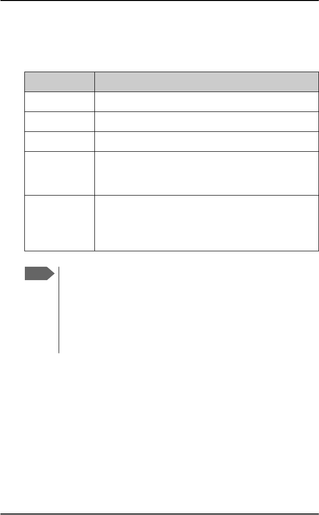
Chapter 3: Calls, faxes and SMS
54 Use a phone or fax machine (SBU)
Dialing prefixes (SBU)
Apart from the numbers above, you can use the following dialing prefixes
before the number:
Prefix Function
1* Forces the connection to use Standard Voice.
2* Forces the connection to use 3.1 kHz Audio.
#31# Hides the caller’s phone number to the recipient.
*31# Shows the caller’s phone number to the recipient
where it would otherwise be hidden, e.g. because the
number is an ex-directory number.
R The following key-presses should activate a
supplementary services function supported by the
system. These function are described in the following
sections.
Note
Which key works as a button to activate supplementary services
varies from phone to phone. To find out which button activates
supplementary services on your handset, refer to the phone’s user
manual. On some digital phones, an R button functions as this
button (like for the Auxiliary Handset). On analog phones without
a dedicated hold button, a short press on the hook button triggers
this function (this is called the flash button on analog phones).
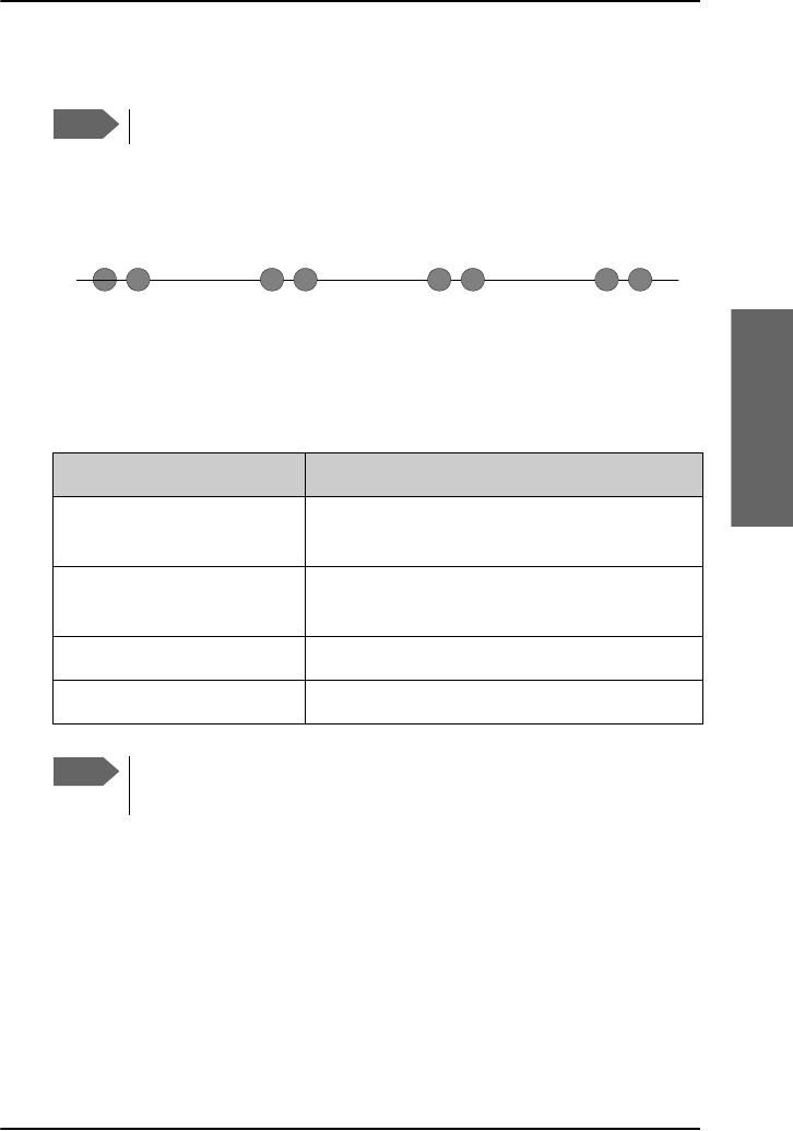
Chapter 3: Calls, faxes and SMS
Use a phone or fax machine (SBU) 55
3333
Calls, faxes and SMS
To handle waiting calls (SBU)
During a local or external call, if a second party attempts to make contact
with you, you may hear a Call Waiting indication. This indication is two
beeps and a pause of 3 seconds, then two beeps again etc. If no action is
taken, the waiting call is released after a time-out period.
In the web interface you can enable or disable the call waiting indication.
For further information how to set-up the call waiting function see the
AVIATOR 700 Installation and maintenance manual.
When you receive a Call Waiting indication, you have the following options:
Note
The phone must have an R key to be able to use these functions.
If you want to: Do as follows:
Clear the current call, and
accept the waiting call.
Press R 1 #, within the time-out period.
Hold the current call, and
accept the waiting call.
Press R 2 #, within the time-out period.
Ignore the waiting call. Take no action.
Reject the waiting call. Press R 0 #, within the time-out period.
Note
The SwiftBroadband system only supports one circuit-switched
call at a time per AVIATOR 700 system.
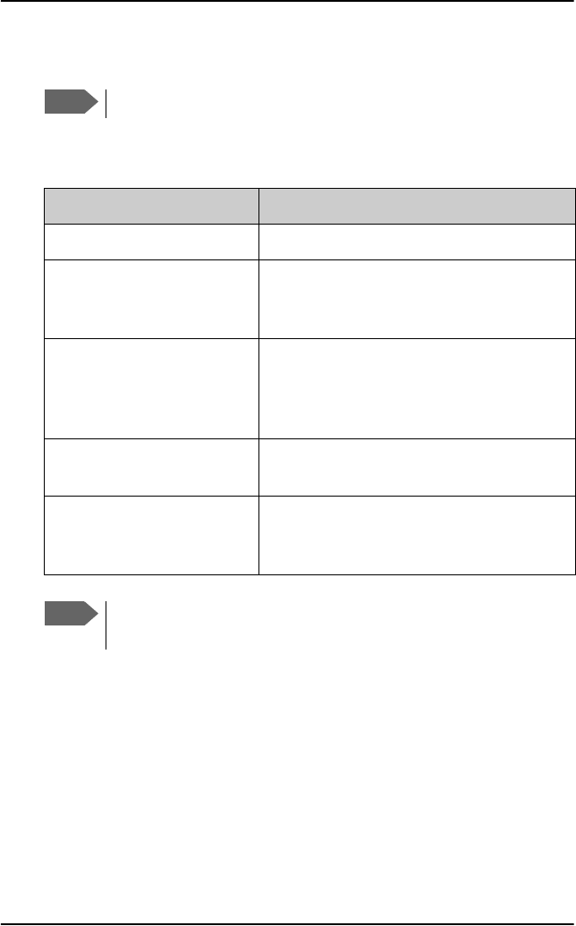
Chapter 3: Calls, faxes and SMS
56 Use a phone or fax machine (SBU)
To hold a call (SBU)
During a local or external call, you may place the initial call on hold while
another call is made.
Note
The phone must have an R key to be able to use these functions.
If you want to: Do as follows:
Place a call on hold. Press R 2 #.
Place the existing call on
hold and establish a new
call.
Press R and dial the second phone number
followed by #.
Shuttle between the two
calls.
Press R 2 #
(irrespective of whether the second call
was acquired using Call Hold or acceptance
of Call Waiting.)
Clear the held call, if no
waiting call exists.
Press R 0 #.
Clear an active call and
return to the held call.
Press R 1 #.
Note that this is only possible if no waiting
call exists.
Note
The SwiftBroadband system only supports one circuit-switched
call at a time per AVIATOR 700 system.
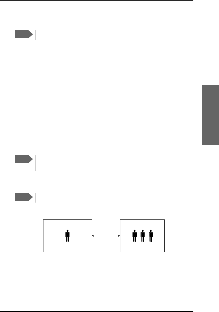
Chapter 3: Calls, faxes and SMS
Use a phone or fax machine (SBU) 57
3333
Calls, faxes and SMS
To transfer a call (SBU)
When you receive a call, you can transfer this call to another phone
connected to the system.
To transfer the incoming call to another phone or headset, do as follows:
1. Press R 4 * <local number> #.
The phone with the local number you dialed starts to ring.
2. You now have two options.
• Hang up. The phone or headset you transferred the call to continues
to ring. When the call is answered, a connection is established
between the initial caller and the new recipient.
• Do not hang up. When the new recipient answers, you can have a
conversation before hanging up. When you hang up, the call is
handed over to the initial caller.
To make a multi-party call (SBU)
Note
The phone must have an R key to be able to use these functions.
Note
The SwiftBroadband system only supports one circuit-switched
call at a time per AVIATOR 700 system.
Note
The phone must have an R key to be able to use these functions.
Ground
Conference
Air
Phone call
(SwiftBroadband)
Conference call (SBU)

Chapter 3: Calls, faxes and SMS
58 Use a phone or fax machine (SBU)
When you have an already established call you can initiate a conference
call by using the following options:
To forward a call (SBU)
You can set up the system to automatically forward incoming calls to
another phone number. This information is saved in the BGAN network so it
is available when the call cannot be put through and must be forwarded.
This service is usually set up by the airtime provider.
To forward incoming calls do as follows:
1. Access the web interface from a connected computer, open a browser
and type the address: http://192.168.0.1 (default). The DASHBOARD
page is displayed.
2. Select SETTINGS > Common > Call forward from the left navigation
pane.
If you want to: Do as follows:
Add an incoming
call announced by
the Call Waiting
indication.
Press R 2 #, the already established call is put on
hold and the incoming call is connected for you to
have an initial conversation with the caller before
the call is added to the conference call.
Then press R 3 #, you are returned to the held calls
and the incoming call is joined in the conference call.
Initiate a new call
and have it joined
to the already
existing call.
Press R <phone number> #, to initiate a new call
and have an initial conversation before the call is
added to the conference call.
Then press R 3 #, you are returned to the held calls
and the initiated call is joined in the conference call.
Clear all calls. Press R 1 # or alternatively just hang-up.
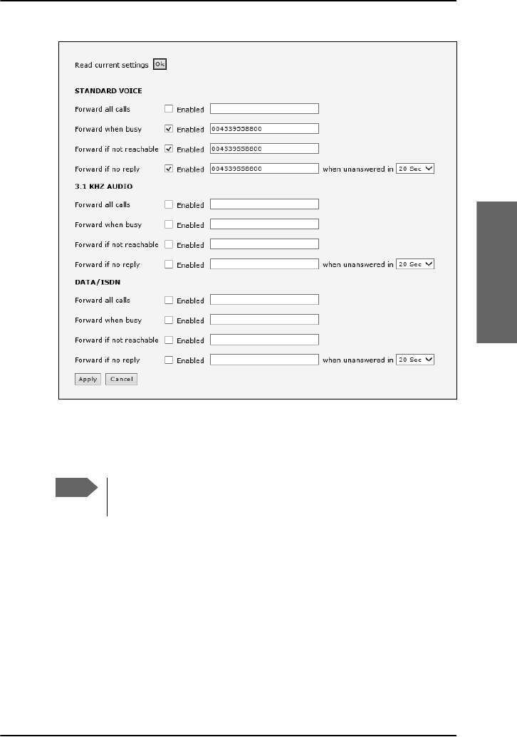
Chapter 3: Calls, faxes and SMS
Use a phone or fax machine (SBU) 59
3333
Calls, faxes and SMS
3. Click OK next to Read current settings to display the phone numbers
for call forwarding for the subscription. These numbers are operator
controlled and come with your airtime subscription (default). A message
saying Operation in progress, please wait. is displayed.
4. For each call type, select Enabled next to the situation(s) in which you
want to forward incoming calls.
5. Next to the enabled items, type in the phone number to forward the call
to.
6. If you have selected Forward if no reply, select from the drop-down
list the period of time to wait before forwarding the call.
7. Click Apply.
Note
Allow sufficient time for the system to read the current
settings over the satellite connection.
Chapter 3: Calls, faxes and SMS
60 Use a phone or fax machine (SBU)
Send or receive a fax message (SBU)
Delay before time-out
When sending or receiving fax messages over a satellite connection, the fax
units at each end of the transmission line must be capable of handling
longer delays without timing out. Some fax machines have an Overseas
mode, which enables the unit to handle the long delays. Make sure that
your fax machine is set to allow long delays before time-out.
To send a fax message (air to ground) (SBU)
The fax machine must be connected to the Phone/Fax interface or the
ISDN interface of the system. See the AVIATOR 700 Installation and
maintenance manual for further details.
3.1 kHz Audio must be used for an analog fax machine. See To select the
default outgoing call type (SDU) on page 35.
UDI must be used for an ISDN G4 fax machine, refer to the AVIATOR 700
Installation and maintenance manual for details how to configure the ISDN
interface.
To send a fax from a fax machine connected to the system, dial
00 <country code> <phone number> #
Example: To send a fax to Cobham SATCOM VA (+1 757 463 9581), dial
00 1 757 463 9581 #
Important
Before sending or receiving fax messages, make sure both
fax units are in “Overseas” mode.
Note
In case the default setting in the web interface is not 3.1 kHz
Audio, dial 2 * before the number, to force the connection to use
3.1 kHz Audio for fax use. For further information, see To override
the default outgoing call type (SDU) on page 36.

Chapter 3: Calls, faxes and SMS
Use a phone or fax machine (SBU) 61
3333
Calls, faxes and SMS
To send a fax message (ground to air) (SBU)
To send a fax message to the system, dial
+ <Mobile number> #
•+ is the prefix used in front of the country code for international calls.
•Mobile number. The first part of the mobile number is always 870,
which is the “country code” for the BGAN system.
To send a fax to a G3 fax use the 3.1 kHz Audio mobile number
To send a fax to an ISDN G4 fax use the UDI number.
The numbers are listed in the documentation from your service
provider. If the mobile numbers are listed in the web interface, you can
look them up as follows:
Connect a computer, access the web interface and select PHONE
BOOK > Mobile numbers. For further information, see To view the
mobile numbers and additional numbers on page 175.
To receive a fax message
An analog fax machine connected to the system can only receive a fax with
3.1 kHz Audio. Refer to To select the incoming call type (SDU) on page 36.
An ISDN G4 fax machine connected to the AVIATOR 700 system can only
receive a fax with a call type UDI.
Important
Before sending or receiving fax messages, make sure both
fax units are in “Overseas” mode.
Note
There are four mobile numbers, one for 3.1 kHz Audio, one for
Standard voice, one for UDI and one for RDI.

Chapter 3: Calls, faxes and SMS
62 Operate the handsets
Operate the handsets
For information how to operate the AVIATOR Wireless Handset see the
AVIATOR Wireless Handset and Cradle, User Manual (order number: 98-
129599). The following handsets are described in detail:
•Operate the Full Feature handset
•Operate the Auxiliary handset
•How to make a call with the Sigma7 handset
•How to make a call with the 2.4GHz Cordless handset
•How to make a call from an ISDN phone
•Use a SIP-enabled IP handset (SBU)
Operate the Full Feature handset
The Full Feature handset is the primary interface
for the AVIATOR 700 system. With the Full
Feature handset you can dial numbers, view
error and status messages, and configure the
transceiver. This handset can only be connected
to the SDU.
The Handset is divided into the following 4
inter-working sections.
• The Liquid Crystal Display (LCD) and Light
Emitting Diodes (LED) section. This section
gives you visual indications about the
operation and status of the system.
• The Function keys section. This section enables you to interact with the
software menu system of the transceiver.
• The Alpha-Numeric section. This section enables you to dial and to
enter data into the transceiver.
• The volume control. A control placed on the side of the handset for easy
adjustment of the volume.
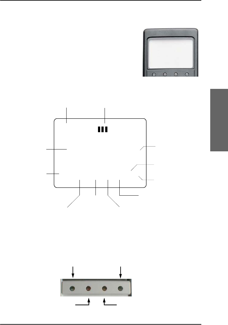
Chapter 3: Calls, faxes and SMS
Operate the handsets 63
3333
Calls, faxes and SMS
Display and LEDs
The following picture shows the top of the
handset with the display and LEDs. The LCD can
be adjusted for contrast and is backlit for viewing
in dim light or at night, see To adjust the LCD
contrast on page 119 and To change the light
settings on page 119.
The LCD display is graphically shown below:
The display contains a set of symbols which, together with the 4 LEDs
situated below the display, continuously indicate the current status.
There are four LEDs below the LCD display.
Ready
AMER AM #1
Scroll Up
Text Area
Scroll Down
Secondary
Functions
Enabled
Locked
Alphabetic
Entry
Enabled
More Options
Available
Handset
Off Hook
Speaker
Enabled
Calls on
Hold
Handset
Number
Classic Aero (H+) Swift 64 (HSD)
Alarm Ringing
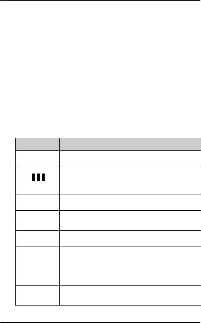
Chapter 3: Calls, faxes and SMS
64 Operate the handsets
•Classic Aero (H+) LED (GREEN): The H+ LED indicates that the system
is logged on to H+ services.
•Alarm LED (RED): The Alarm LED illuminates when the system detects a
fatal or essential fault. An error code is also shown in the display.
•Ringing LED (AMBER): The Ringing LED flashes when the handset is
ringing. When a connection is established the LED is turned off.
•Swift64 LED (GREEN): The Swift64 LED indicates that the system is
logged on to Swift64 services. Note that this LED is not lit when the
system is logged on to an I4 satellite providing SwiftBroadband
services.
Display symbols
The below list shows the meaning of each of the various symbols, that may
appear in the display.
Symbol Meaning
YMore menu entries above.
Calls on hold.
Each bar represents a call on hold. In this example there
are 3 calls on hold.
ZMore menu entries below.
]The G key has been pressed. The 2nd function will be
used for the next key pressed.
^A valid PIN code is required to use the terminal.
_The keypad is in alpha mode. Alpha mode is used to
enter letters (for example names in the phone book).
Note: This symbol does not indicate capital letters.
The U key is used to toggle the Caps lock function.
`The value in a menu must be selected between certain
predefined values by means of the B and E keys.
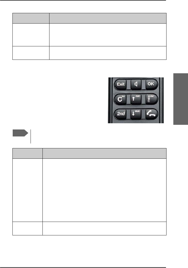
Chapter 3: Calls, faxes and SMS
Operate the handsets 65
3333
Calls, faxes and SMS
Function keys
The Function keys enable you to enter the
menu system of the transceiver and change
various settings.
The below list shows the meaning of the
function keys.
aThe speaker. You can turn the external speaker on and
off by pressing H. The a symbol is displayed in the
LCD when the speaker is on.
bThe handset is off hook
Symbol Meaning
Note
You access the second function of a key by pressing G before
pressing the key.
Key Function
AExit key:
• In the Menu system, pressing Exit brings you back one
level until the menu is completely exited.
• When you are asked YES or NO by the system, pressing
Exit is interpreted as a NO response.
• When you are entering data into the transceiver,
pressing Exit cancels the entry.
• Second function: Leave the menu system.
HSpeaker key: This key turns the external speaker on and off.

Chapter 3: Calls, faxes and SMS
66 Operate the handsets
COK key:
• When in the main screen display, pressing OK enters
the menu system.
• When in the menu system, pressing OK enters the
selected menu.
• When entering data, such as phone numbers or PIN
codes, pressing OK applies the entry.
• When you are asked YES or NO by the system, pressing
OK is interpreted as a YES response.
DClear key:
• The primary function is to clear the last entered digit.
• Second function: Insert.
The insert function is used to insert new phone book
entries, etc.
BScroll up key:
• The primary function is to enable you to scroll up to
menu items not shown on the 2-line display of the LCD.
• Second function: Edit.
The Edit function allows you to edit previously entered
information, for example phone book entries.
FABC key:
• The primary function of this key is to toggle between
normal mode and alpha numeric mode.
• Second function: Delete.
The Delete function allows you to delete previously
entered information, for example phone book entries.
GThe 2nd function of the next key pressed will be applied.
Key Function

Chapter 3: Calls, faxes and SMS
Operate the handsets 67
3333
Calls, faxes and SMS
EScroll down key:
• The primary function is to enable you to scroll down to
menu items not shown on the 2-line display of the LCD.
• Second function: Mute.
The Mute function turns the handset microphone
on/off.
I• When pressed after a number, I initiates a call.
• When pressed during a phone call, I ends the call.
• When pressed without a connection and without any
numbers entered, I shows a list of the ten last
dialled numbers. When pressed again, I dials the
selected number.
Key Function
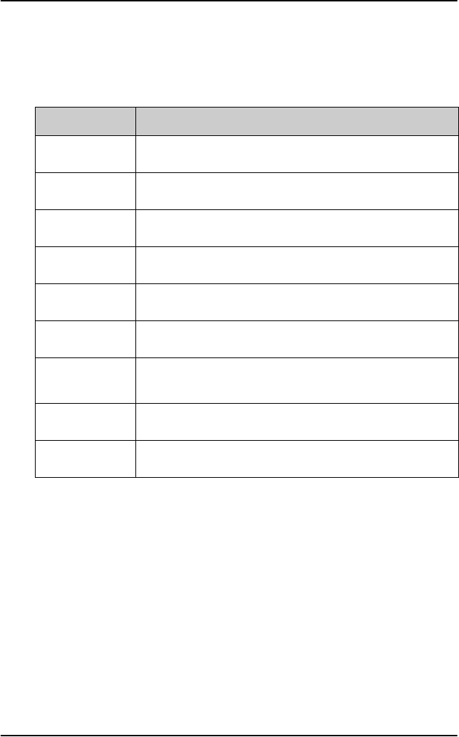
Chapter 3: Calls, faxes and SMS
68 Operate the handsets
Second functions
A number of keys have a 2nd function. The following table gives a total
overview of all the 2nd functions.
Keys Function
GJ Enters the top level of the menu system.
GS Transfers the call to a specified handset.
GT Places a call on hold.
GU Joins other handsets to a call.
GD Inserts an entry, for example in the phone book.
GB Edits an existing entry, for example in the phone book.
GF Deletes an existing entry, for example in the phone
book.
GE Mute. Turns the handset microphone on/off.
GA Exits the menu system from anywhere in the menus.

Chapter 3: Calls, faxes and SMS
Operate the handsets 69
3333
Calls, faxes and SMS
Alpha-numeric keys
The keypad can be in normal (numeric)
mode or alpha mode. Normal mode is used
to enter digits (phone numbers) whereas
alpha mode is used to enter letters (such as
names in the phone book).
Switch alpha/numeric mode
The F key is used to switch between the
two modes. The _ symbol in the display
indicates that the handset is in alpha mode.
Enter letters
In alpha mode you can use each of the numeric keys to select between
subsets of the alphabet and certain special characters. To enter a letter,
press the key a number of times until the wanted character is shown in the
display. For example, to insert the letter C, you press the K key 3 times in
alpha mode.
Caps Lock toggle
The U key is used as a Caps lock toggle when the handset is in alpha
mode.
S Key
The S key is a special function key, which is normally used only in
numeric mode.

Chapter 3: Calls, faxes and SMS
70 Operate the handsets
Available characters in alpha mode
Below is an overview of the relevant keys in alpha mode.
Key Available characters or functions in alpha mode
J- ? ! , . : ’ $ ( ) + / 1
KA B C 2
LD E F 3
MG H I 4
NJ K L 5
OM N O 6
PP Q R S 7
QT U V 8
RW X Y Z 9
T<space>
UCaps lock toggle

Chapter 3: Calls, faxes and SMS
Operate the handsets 71
3333
Calls, faxes and SMS
How to make calls from the Full Feature
handset
Before making a call make sure the display shows “Ready” or that the
service you want to use (H+ or SW 64) is available, i.e. the service LED for
Classic Aero (H+) is lit.
Do as follows:
1. Type in the phone number with the prefix 00.
Example: To call Cobham SATCOM VA (+1 757 463 9557), press the
number:
TT for Voice,
J for country code,
then PNPMOLRNNP
2. Press I, C or U to activate the call.
The display on the terminal handset shows how the call proceeds.
3. Hang up by pressing I or placing the handset in the cradle. When the
call is terminated, the display shows the duration of the call.
Example:
The phone book can also be used to initiate a call, either by selecting an
entry in the phone book or by using the Quick Dial function.
Answer a call
Answering a call to the Full Feature handset can be done in two ways:
• If the handset is in the cradle, simply take the handset from the cradle
to answer the call.
• If the handset is out of the cradle, press I to answer the call.
Connected:
00:01:59

Chapter 3: Calls, faxes and SMS
72 Operate the handsets
To make a call using the phone book
The phone book can be used to initiate a call.
For information on how to insert or edit entries in the phone book, see Use
the SDU phone book on page 115.
To make a call using the phone book, do as follows:
1. Press B or E to access the phone book from the main display, or
enter the menu system and select PhoneBook.
2. Find the entry you need, either by scrolling the list with B or E, or
by pressing the key holding the first letter of the entry.
Example: To find an entry with the name Jones, press N once. To
find an entry with the name Larsen, press N three times.
3. Press I, C or U to dial the selected number.
Quick Dial function
To use the Quick Dial function, press one of the J R keys and hold
it down for 1 sec. Each key is a shortcut to a user-defined entry in the
phone book. For further information, see the section System Setup,
Quick Dial on page 135.
To redial a number
To call the last used number, press I to show a list of the last ten
numbers dialled from the handset.
Scroll through the list and press I, C or U to establish a call to the
selected number.
Note
The list only shows the first 12 digits of each number.

Chapter 3: Calls, faxes and SMS
Operate the handsets 73
3333
Calls, faxes and SMS
Operate the Auxiliary handset
The Auxiliary handset is divided into 3 sections.
•LEDs: This section gives you visual indications about
the operation and status of the system.
•Function keys: This section gives you access to a
few call functions, such as transfer of calls, memory
etc.
•Alpha-Numeric keys: This section enables you to
dial numbers.
The Auxiliary handset also provides a volume control
placed on the side of the handset.
LEDs
There are two LEDs on the Auxiliary handset.
• Left green LED: Lights constantly when the handset is off-hook.
• Right green LED: Flashes to indicate that the handset is ringing.
When a connection is established, the LED is turned off.
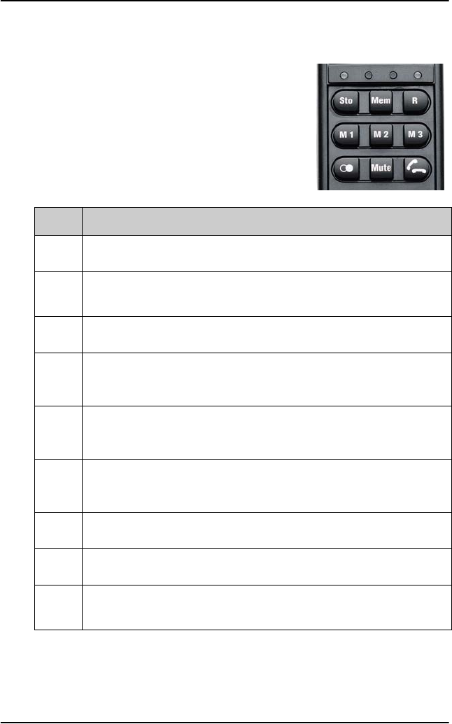
Chapter 3: Calls, faxes and SMS
74 Operate the handsets
Function keys
The function keys enable you to transfer calls,
redial, store and recall phone numbers, and to
mute the microphone.
Each function key is described in detail in the
table below.
Key Function
GStore number. This key is used to store phone numbers.
HMemory. This key is used to recall phone numbers from the
memory.
FThis key is used to put calls on hold.
AMemory location 1.
(Same function as H J)
BMemory location 2.
(Same function as H K)
CMemory location 3.
(Same function as H L)
DRedial. This key is used to redial the last dialled number.
EMute. This key is used to mute the microphone.
IToggle hook. This key is used to toggle between on-hook and off-
hook.
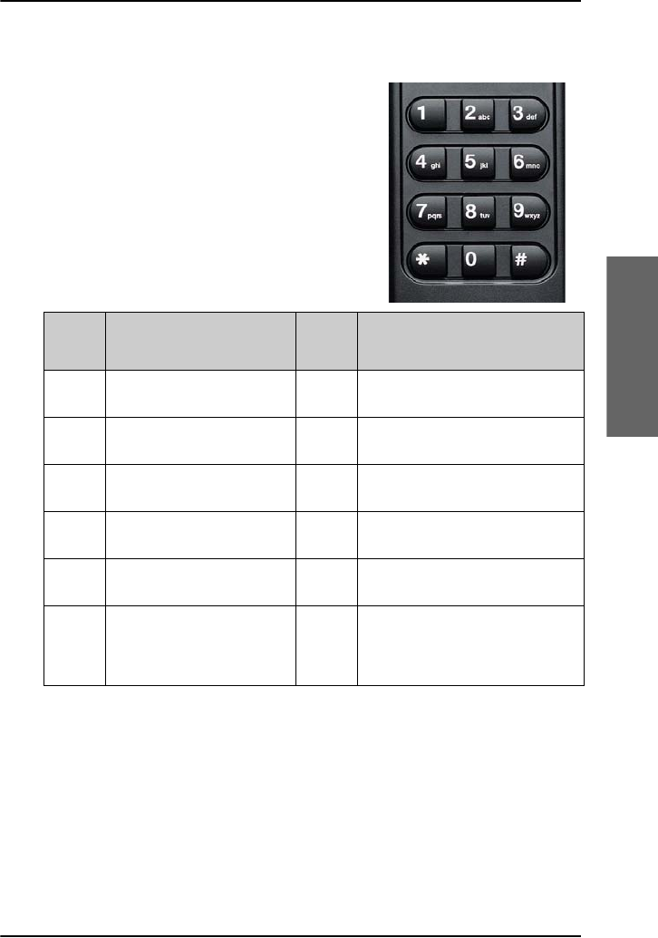
Chapter 3: Calls, faxes and SMS
Operate the handsets 75
3333
Calls, faxes and SMS
Alpha-Numeric keys
The numeric keys are primarily used to dial
numbers or to enter numbers to be stored in
memory.
Below is an overview of the available
characters and functions.
Key Available Characters
or Functions Key Available Characters or
Functions
J1P7 p q r s
K2 a b c Q8 t u v
L3 d e f R9 w x y z
M4 g h i SSpecial function
N5 j k l T0
O6 m n o UThis key is used to indicate
the end of a phone number or
to activate a call.

Chapter 3: Calls, faxes and SMS
76 Operate the handsets
How to make calls from the Auxiliary
Handset
Before making a call, make sure you hear a dial tone in the handset.
Making a call from an Auxiliary Handset connected to an analogue POTS
phone interfaces is done in the same way as a call from a standard
telephone, but always with the prefix 00 and U after the number to
signal to the terminal, that the number is complete.
Example: To call Cobham SATCOM VA (+1 757 463 9557) first establish
a connection by pressing I or taking the handset off the
cradle. Then press the following keys on the phone:
TTJPNPMOLRNNPU
How to make Internal calls see To make local phone calls (SDU) on
page 39.
To take a call
Taking a call to the Auxiliary handset can be done in two ways:
• If the handset is in the cradle, take the handset from the cradle to take
the call.
• If the handset is out of the cradle, press I to take the call.
To store a phone number
The Auxiliary handset can store up to 10 phone numbers, in memory
location 0 to 9. The A, B and C keys can be used for accessing
memory location 1, 2 and 3, whereas the other locations are accessed using
the MEM key followed by the number of the location.
To store a number using A, B and C, d, do as follows:
1. Press I or take the handset off the cradle.
2. Press G.
3. Enter the phone number you want to store, including country code.

Chapter 3: Calls, faxes and SMS
Operate the handsets 77
3333
Calls, faxes and SMS
4. Press G.
5. Press A, B or C depending on the memory location you want to
save the number in.
The number is now available in the memory location you selected.
Example: To save the phone number of Cobham SATCOM VA in
memory location 2, take the handset off the cradle and
press the following keys:
G
TTJPNPMOLRNNP
G
B
To store a number using the number keys, do as follows:
1. Press I or take the handset off the cradle.
2. Press G.
3. Enter the phone number you want to store, including country code.
4. Press G.
5. Press one of the keys 0 to 9, depending on the memory location you
want to save the number in.
The number is now available in the memory location you selected.
Example: To save the phone number of Cobham SATCOM VA in memory
location 8, take the handset off the cradle and press the
following keys:
G
TTJPNPMOLRNNP
G
Q

Chapter 3: Calls, faxes and SMS
78 Operate the handsets
To recall a phone number from memory
To recall a phone number from memory location 1, 2 or 3 using the
A, B and C keys, do as follows:
1. Press I or take the handset off the cradle.
2. Press A, B or C, depending on which memory location you
want.
The number saved in the memory location is dialled.
3. When calling from the SBU finish by pressing U.
Example: To call the number saved in memory location 3, first establish a
connection by pressing I or taking the handset off the
cradle. Then press C. The number saved in memory location
3 is dialled.
To recall a phone number from memory using the H and the
number key, do as follows:
1. Press I or take the handset off the cradle.
2. Press H followed by the number of the memory location you want.
The number saved in the memory location is dialled.
3. When calling from the SBU finish by pressing U.
Example: To call the number saved in memory location 8, first establish a
connection by pressing I or taking the handset off the
cradle. Then press H Q. The number saved in memory
location 8 is dialled.
To redial a number
To call the last dialled number, first establish a connection by pressing I
or taking the handset off the cradle. Then press D followed by U.
Note
Pressing A has the same effect as pressing H J.

Chapter 3: Calls, faxes and SMS
Operate the handsets 79
3333
Calls, faxes and SMS
To mute the microphone
To mute the microphone of the handset, press E. To return to normal
microphone function, press E again.
How to make a call with the Sigma7 handset
To make a call using the Sigma7 handset, do as follows:
1. Press the On key.
2. Type in the phone number with the prefix 00.
3. Press #.
Example: To call the number of Cobham SATCOM VA (+1 757 463
9557), press the On key followed by the number:
00 for Voice, 1 for country code,
then 757 463 9557 #.
•To hang up, press the Off key or place the handset in the cradle.
•To answer a call, take the handset out of the cradle and press the On
key.
For further information on the functions of the Sigma7 handset, refer to:
“Sigma7 Telephone Handset Manual”, PN# 500114.
Note
If you cannot adjust the handset volume correctly, it may be
because the configuration of the AVIATOR 700 system and the
configuration of the handset do not match. Please contact your
Maintenance Center to have them reconfigure the system
correctly.

Chapter 3: Calls, faxes and SMS
80 Operate the handsets
How to make a call with the 2.4GHz Cordless handset
To make a call using the 2.4GHz Cordless handset, do as follows:
1. Type in the phone number with the prefix 00.
2. Press #.
3. Press the TALK key.
Example: To call Cobham SATCOM VA (+1 757 463 9557), dial:
00 for Voice, 1 for country code,
then 757 463 9557 #, followed by the TALK key.
•To hang up, press the END key or place the handset in the cradle.
•To answer a call, take the handset out of the cradle and press the
TALK key.
For further information on the functions of the 2.4GHz Cordless handset,
refer to: “2.4GHz Cordless, Installation Manual”, PN# 500484.
How to make a call from an ISDN phone
Making a call from a phone connected to the ISDN interface is similar to
making a call from the POTS handset, that is, you have to press # to indicate
the end of the number.
Example: To call Cobham SATCOM VA (+1 757 463 9557), establish a
connection by pressing I or taking the handset off the
cradle.
Then dial: 00 1 757 463 9557 #.
Operate the AVIATOR Wireless Handset
See the AVIATOR Wireless Handset User Manual.

Chapter 3: Calls, faxes and SMS
Operate the handsets 81
3333
Calls, faxes and SMS
Use a SIP-enabled IP handset (SBU)
SIP-enabled wireless IP handset
The SBU of the AVIATOR 700 system has in integrated SIP server. If your
mobile phone is a SIP enabled IP handset, it has a SIP client. Then you can
set it up and use it to make phone calls or use other data services using the
SwiftBroadband service.
Once set up, you can use the SIP-enabled IP handset as a local phone
during flight. When calling you use the SwiftBroadband service. The call
costs will be charged to the SwiftBroadband subscriber. The call receiver will
be called up from the system’s 870 number.
When your device is connected to the SIP server of the AVIATOR 700
system you cannot be called at your own mobile number and you cannot
send or receive SMS messages.
To set up a SIP-enabled wireless IP handset (SBU)
To set up a SIP enabled IP handset, do as follows:
1. Connect to the Wireless access point of the AVIATOR 700 system.
Check that the WLAN icon in the handset display indicates that the
WLAN connection has been established. If your WLAN is encrypted
check with your system administrator how to proceed to access the
encrypted WLAN network.
2. Connect to the SIP server of the AVIATOR 700 system. See the user
manual of your IP handset for guidelines how to establish a connection
to a SIP server.
Note
Check whether your mobile phone or Smart Phone has a wireless
interface and an integrated SIP client.

Chapter 3: Calls, faxes and SMS
82 Operate the handsets
For this you need to enter the following details into the device:
• SIP server name, port and address, default: 192.168.0.1
•User name
•Password
•Codec priority
•Realm
User name: When connecting to a SwiftBroadband Unit, the user name
should be a local number, i.e. 05xx. This must be configured in the built-in
web interface under SETTINGS > IP handsets.
Password: When connecting to a SwiftBroadband Unit, the password is
the local number for this phone. It is a number in the range of 0501 to 0516
which is not yet assigned to other IP phones. The password must match the
IP Handset password entered in the SwiftBroadband Unit.
Codec priority: Select the codec type that should have the highest
priority. You may select G.711 A-LAW.
Realm: When asked for Realm enter the serial number of the AVIATOR 700
SBU.
Having established this connection you can make calls with SIP-enabled IP
handset and it can be called to, also as a local phone of the AVIATOR
700system.
Note
All charges for calls and data sessions are billed to the AVIATOR
700 system.
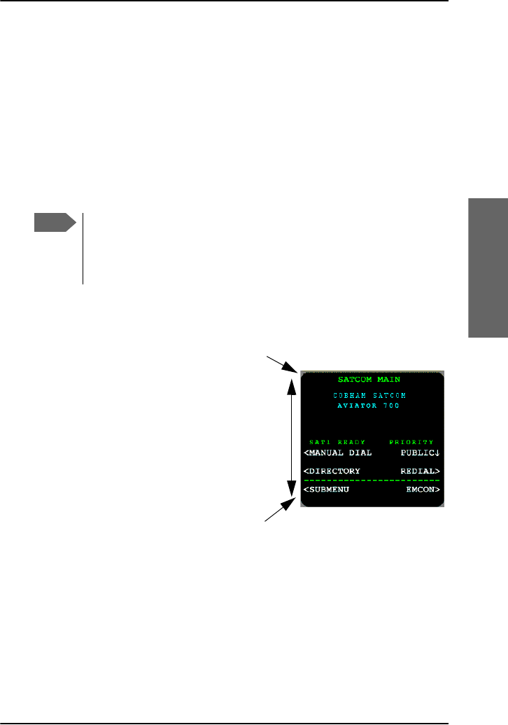
Chapter 3: Calls, faxes and SMS
Use the MCDU 83
3333
Calls, faxes and SMS
Use the MCDU
Operate the MCDU
The MCDU is used to control and operate the SATCOM equipment from
the cockpit. A subset of the MCDU menus and functions are identical to
those of the Full Feature handsets. The following sections describe the
AVIATOR 700 menu functions of the MCDU and explain how to navigate
the MCDU.
MCDU display
The MCDU display holds 14 rows of
24 characters each. The top line is
the title line and the bottom line (the
Scratch Pad) is used to display
messages to the crew and to show
keyboard entry of data.
If the contents consist of multiple
pages, the current page and total
number of pages are displayed on
the first line. Press the keys NEXT
and PREV to view all pages.
Note
This chapter only describes the part of the MCDU functions that
concerns the AVIATOR 700 system. For information on other
functions in the MCDU, refer to the documentation delivered with
your MCDU and, if relevant, with any other connected equipment.
Scratch pad
14 rows
Title line

Chapter 3: Calls, faxes and SMS
84 Use the MCDU
Navigation: Display text and symbols
The below list shows the meaning of most of the various symbols and texts
that may appear in the display.
Symbol/Text Meaning
<
or
>
These symbols appear next to the arrow keys ( ).
The name next to this symbol indicates a new page.
Pressing the arrow key next to this symbol opens the
new page, e.g. a submenu.
*This symbol (star or asterisk) appears next to a key if
pressing that key causes the activation of a function.
The displayed page may also change as a result.
ZThis symbol indicates the currently selected parameter
in a list. Pressing the arrow key next to this symbol
toggles between the settings available.
MAIN Pressing the arrow key next to MAIN causes the
display to exit the menu system and go to the top-level
page.
RETURN Pressing the arrow key next to RETURN causes the
display to go up one level in the menu system.
ACTIVE
ERRORS
If an error has occurred, this text is shown. Press the key
next to ACTIVE ERRORS to see a list of currently
active errors.
INCOMING
CALL
If there is an incoming call, this text is shown. Press the
key next to REJECT to reject the call, or the key next
to ACCEPT to accept it.

Chapter 3: Calls, faxes and SMS
Use the MCDU 85
3333
Calls, faxes and SMS
MCDU keys
The below list shows the most important key functions in the MCDU. Note
that some keys may be marked differently, depending on the type of
MCDU.
Symbol/Text
on key Function
MENU Enters the top-level menu. In this menu you can select
SUBMENU.
or
(arrow keys)
Opens a new page, changes parameters or activates a
function, depending on the symbol next to the key.
For further information, see Display text and
symbols on the previous page.
NEXT Opens the next page, if the current menu or list contains
more than one page.
The top right corner of the display shows whether there
are more pages. Example: 1/3.
PREV Opens the previous page, if the current menu contains
more than one page.
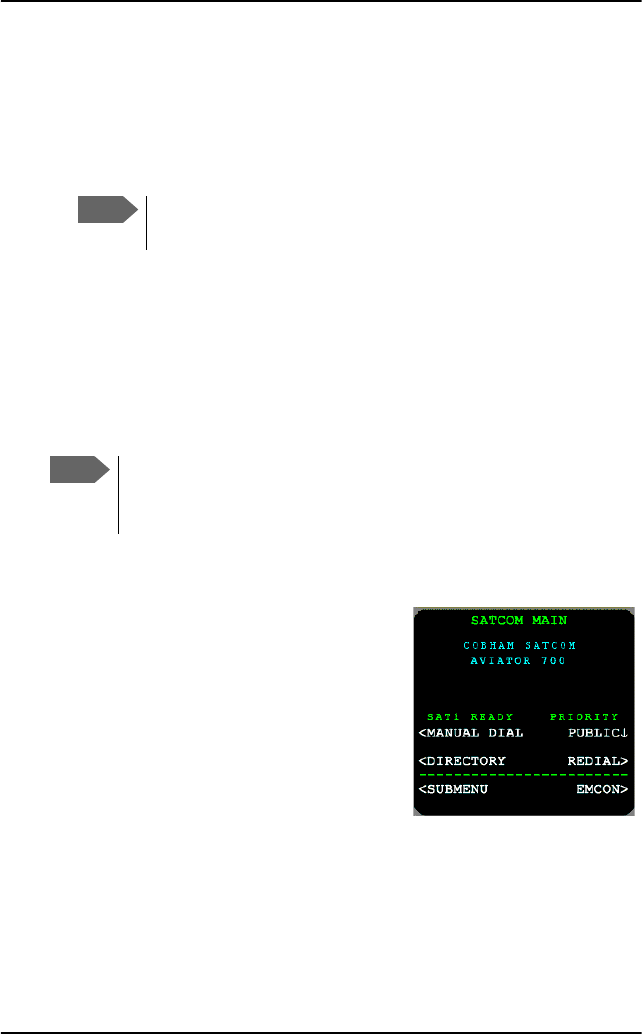
Chapter 3: Calls, faxes and SMS
86 Use the MCDU
To enter the SATCOM subsystem
To enter the SATCOM subsystem of the MCDU, do as follows:
1. Press the MENU key.
The display shows a list of connected devices (subsystems).
2. Press next to the name of your connected AVIATOR 700 system.
If you want to change the device name shown in the display, use the
Aero-SDU Configuration Program.
When the SATCOM subsystem is selected, the display shows the menu
SATCOM MAIN after a successful POST and calibration procedure. Once in
the SATCOM subsystem, the title line of the display shows the name of the
current menu.
Automatic logon
When the system has completed its
initialization, and if the logon policy is set to
automatic, the system will initiate the logon
procedure. Upon successful logon, the
MCDU display shows:
For further information on this menu see
AVIATOR 700 main menu on page 150. For
the complete MCDU AVIATOR 700 menu
tree see Menu trees on page 211.
Note
Depending on the type of MCDU, the MENU key may have a
different name. Refer to the documentation for your MCDU.
Note
During the start-up of the AVIATOR 700 system, that is when the
POST and calibration procedures are running, the Main menu will
not be ready
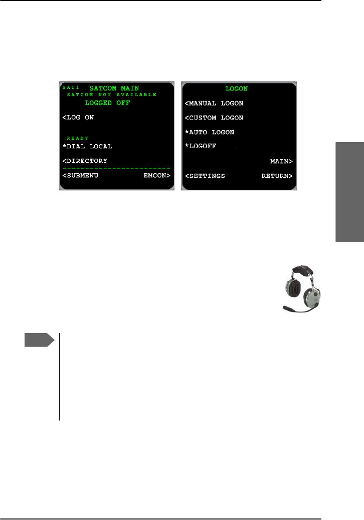
Chapter 3: Calls, faxes and SMS
Use the MCDU 87
3333
Calls, faxes and SMS
Manual logon
When the system has completed initialization, and if the logon policy is set
to manual, the system will stay logged off and wait for user input. In this
case, only a subset of the features in the main menu is available.
Select the LOG ON menu to proceed. For further information on this menu
see LOGON menu on page 153.
Make or receive a phone call (MCDU)
This section explains how to make a call from the MCDU. Call
routing from and to the cockpit can be configured as
described in To select the default outgoing call type (SDU)
on page 35 and To select the incoming call type (SDU) on
page 36.
Note
There are two modes for activating or terminating a call: Latched
or Push-To-Talk (PTT). This is set-up in the Aero-SDU
Configuration Program.
In PTT mode you can activate a call by pushing the PTT button or
using the keypad of the MCDU as described below. If the system
is in Latched mode, you must use the switch to activate and
terminate the call.
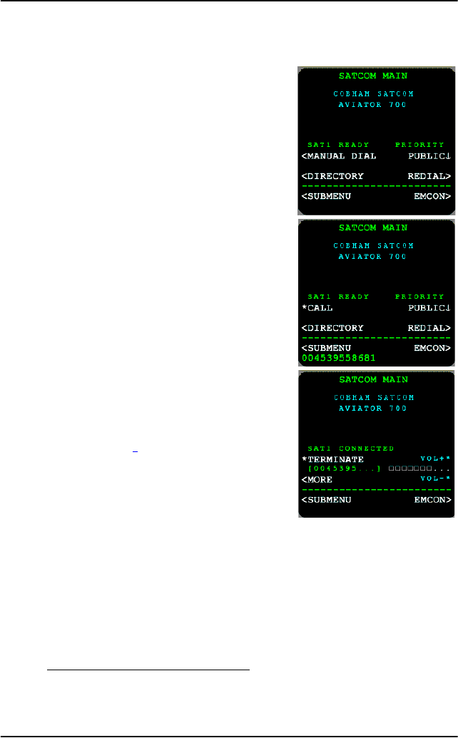
Chapter 3: Calls, faxes and SMS
88 Use the MCDU
To make a call (air to ground) (MCDU)
You can dial a phone number from two
views in the MCDU:
• Main menu
•MANUAL DIAL menu
The main menu is shown here.
To make a call, do as follows:
1. Dial 00 <country code> <phone
number> using the numeric keys on the
MCDU and select CALL1.
Example: To call the phone number
39558681 in Denmark, Europe,
that has the country code 45
press 004539558681 and then
press CALL.
2. To terminate the call, select
TERMINATE1 or use the latch key.
While having an active call, the volume can
be adjusted from main menu, or the
submenu MORE, you can put the call on
hold, transfer it or join a conference call. For
further information see To hold a call (MCDU) on page 92, To transfer a
call (MCDU) on page 92 and Conference call (MCDU) on page 93.
If the outgoing call type (see also Select a call type (SDU) on page 34) is
Standard Voice (H+), a Classic Aero Call Priority can be assigned to the call.
For more information on call priorities see AVIATOR 700 main menu on
page 150.
1. If in latched mode, activate the call by switching on the Mic Switch.
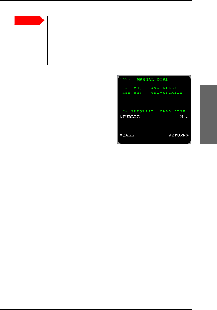
Chapter 3: Calls, faxes and SMS
Use the MCDU 89
3333
Calls, faxes and SMS
From the MANUAL DIAL menu, you
can override the default outgoing call
type. Configure the Call Priority before
selecting CALL. Use the arrow key next
to Call Type to select between the
settings available. The types are listed
here:
• Auto. The default outgoing call type
is used, see also Select a call type
(SDU) on page 34.
•H
+. Use only the Classic Aero (H+) service (Standard Voice).
• HSD. Use only the Swift64 (HSD) service.
To receive a call (MCDU)
By default, all devices connected to the 4-Wire interfaces, 2-Wire interface
and the ISDN interface will ring when one of the mobile numbers is called.
Note, however, that this depends on the configuration of incoming calls
made during initial configuration of the system. For further information, see
the AVIATOR 700 Installation and maintenance manual and the online help
of the Aero-SDU Configuration Program.
To make a call (ground to air) (MCDU)
For information how to make a call to the system see Phone number for a
call (ground to air) (SDU) on page 38.
Important
It is recommended to use default call routing for cockpit
audio to avoid the risk that an emergency call can be routed
as a Swift64 call.
If you select an H+ call priority higher than Public, other calls
with lower priority will automatically be released in case of
congestion in the aircraft system or in the Inmarsat network.

Chapter 3: Calls, faxes and SMS
90 Use the MCDU
To make a local phone call (MCDU)
You can make a local phone call from several views in the MCDU:
• Main menu
•MANUAL DIAL menu
You can also make local calls when the system is logged off the satellite
services.
To make a local phone call, do as follows:
1. To make a local phone call dial the interface code and select CALL1
For a list of interface codes, see Special-purpose and local numbers on
page 40.
2. To make a local broadcast to all connected phones use interface code 0
and select CALL1.
To make a call using the phone book (MCDU)
The phone directory contains the prioritized subdirectories Emergency,
Safety, Non-safety and Public. Emergency has the highest priority, Safety
the second-highest and so forth. The Public directory is also accessible from
the Full Feature handsets.
To call a number in the phone book, do as follows:
1. Enter the DIRECTORY menu from the main menu.
1. If in latched mode, activate the call by switching on the Mic Switch.
Important
If you select an H+ call priority higher than Public, other calls
with lower priority will automatically be released in case of
congestion in the aircraft system or in the Inmarsat
network.
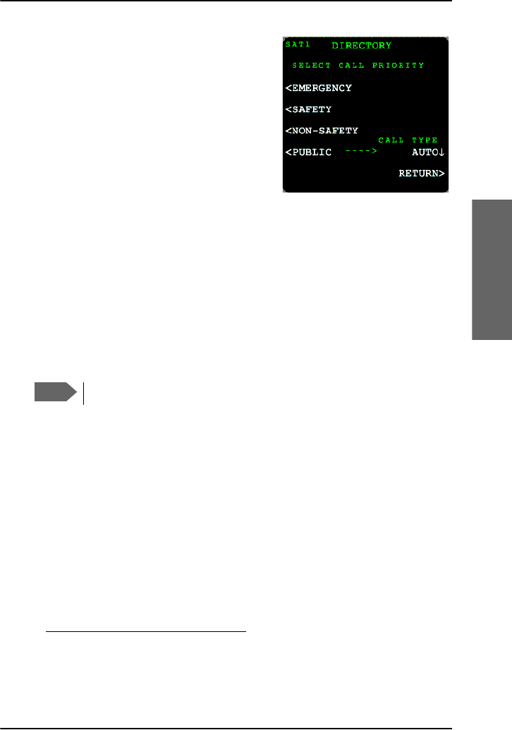
Chapter 3: Calls, faxes and SMS
Use the MCDU 91
3333
Calls, faxes and SMS
2. Select a call priority: EMERGENCY,
SAFETY, NON_SAFETY or PUBLIC
to display the phone book entries for
this call priority. If you want to
override the call type press Auto and
select H+ or HSD.
3. Select the number you want to call1.
The display lists all numbers assigned
to the selected call priority. If there is
more than one page, use the keys PREV and NEXT to scroll through the
pages.
To redial a number (MCDU)
To redial a number, do as follows:
1. Select REDIAL. The display shows a list of the last 10 called numbers.
2. Select the number you want to dial.2
A call to the selected number is activated.
To handle incoming calls using the switchboard (MCDU)
The switchboard makes it more straight forward to handle incoming calls.
When an incoming call is established, do as follows:
1. Enter the menu MORE and select SWITCHBOARD.
The display shows a list of all connected handsets and their current
states:
•READY — the handset is free for a call.
•BUSY — the handset is currently used for a call.
1. If in latched mode, activate the call by switching on the Mic Switch.
2. If in latched mode, activate and terminate the call by switching the Mic
Switch.
Note
Systems with two MCDUs share the redial list.

Chapter 3: Calls, faxes and SMS
92 Use the MCDU
2. Press the key next to the handset you want to talk to and wait until the
handset you just selected answers the call.
3. Select CONFERENCE to add the handset to the conference call or
TRANSFER to put the call through to the handset.
To hold a call (MCDU)
When the connection is established, you can put an incoming, outgoing or
local call on hold. To put a call on hold do as follows:
1. Enter the MORE menu (accessible from the main menu).
2. Select HOLD.
The display shows that the call is put on hold. After a call has been placed
on hold, a new call can be initiated.
To reactivate a call placed on hold, do as follows:
1. Enter the MORE menu (accessible from the main menu).
2. Select UNHOLD.
To transfer a call (MCDU)
To transfer an incoming or outgoing call to a local phone connected to the
SDU do as follows:
1. Establish a connection to the incoming or outgoing call.
2. Enter the menu MORE and select HOLD.
3. Press the interface code and select CALL. For a list of interface codes,
see Special-purpose and local numbers on page 40.
4. Enter the menu MORE and select TRANSFER.
To transfer a local call to another local phone or an outgoing call do as
follows:
1. Establish a connection to the local phone.
Note
Only one call can be on hold at a time.

Chapter 3: Calls, faxes and SMS
Use the MCDU 93
3333
Calls, faxes and SMS
2. Enter the menu MORE and select HOLD.
3. Press the interface code of the local phone or the phone number of an
outside phone and select CALL.
4. Enter the MORE menu and select TRANSFER.
Conference call (MCDU)
You can establish a conference between three or more phone parties.
When a call is already established, do as follows to add additional parties:
1. Enter the menu MORE and select HOLD.
2. Press the interface code of the local phone or the phone number of an
outside phone and select CALL. For a list of interface codes, see
Special-purpose and local numbers on page 40.
3. Enter the menu MORE and select CONFERENCE to add the handset to
the conference call.
4. To add more parties to the conference call, repeat steps 1 to 3.
5. To leave the conference, select TERMINATE from the main menu.
Note
It is not possible to transfer an outgoing/incoming call to a second
outgoing/incoming call. At least one party must be a local phone
connected to the SDU.
Note
Max. 6 lines can be connected, including handsets on the aircraft
and lines to the ground.
Note
When the last local phone exits the conference call, the
conference call is terminated even though there may be two or
three active incoming or outgoing callers.
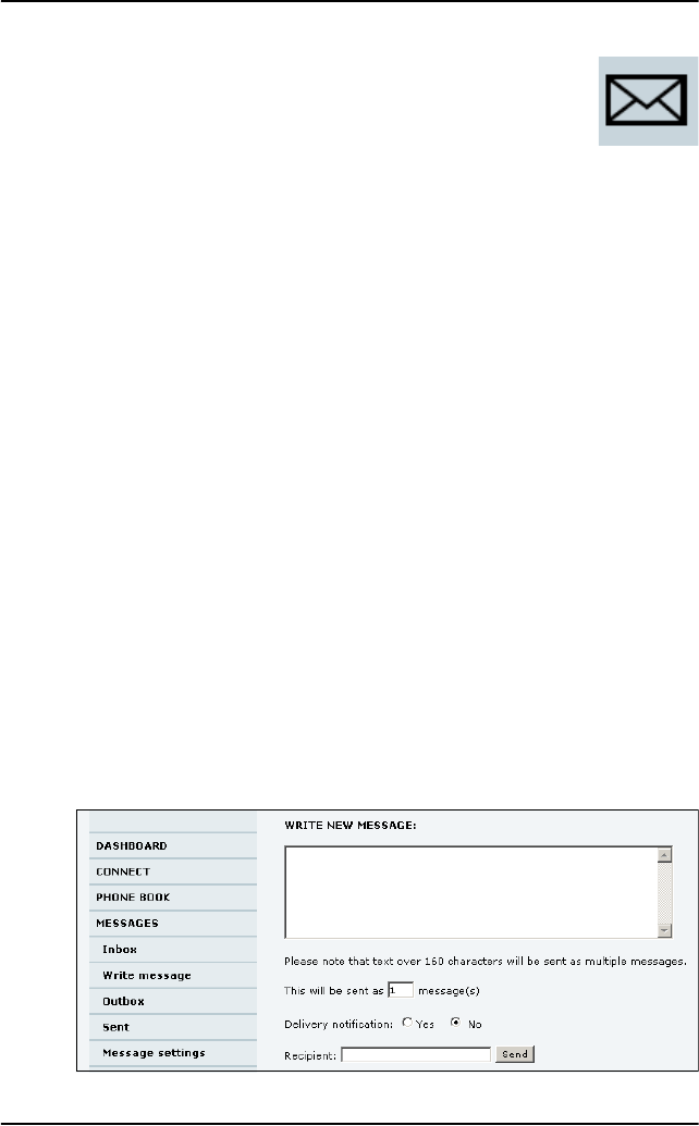
Chapter 3: Calls, faxes and SMS
94 SMS service
SMS service
Introduction
The SMS service provided by the SBU lets you send and receive short text
messages from and to the satcom system. Theses messages are public and
stored in the system, they can be viewed by all system users. The SMS
service is also used to alert you that a voice mail has been received.
This message service does not manage personal SMS messages to and from
personal IP devices.
To send an SMS message
You can send and receive SMS messages using the SBU of the AVIATOR
700 system. To do this you must connect a computer to the system using a
LAN or WLAN connection and access the web interface.
To send an SMS message from the system, do as follows:
1. Access the web interface from a connected computer, open a browser
and type the address: http://192.168.0.1 (default). The DASHBOARD
page is displayed.
2. Click MESSAGES from the left navigation pane.
This page contains new incoming messages. On this page you can
archive the messages and move them to the Inbox or you can delete a
message.
3. In the left navigation pane, click Write message.

Chapter 3: Calls, faxes and SMS
SMS service 95
3333
Calls, faxes and SMS
4. Type in the message in the Write new message field.
If the message text is too long for one SMS, the message is sent as two
or more SMS messages. The field below the message field shows the
number of SMS messages used to send the message.
5. Type in the phone number in the Recipient field.
Remember 00 or + and country code (e.g. 00 45 to call Denmark or
00 1 to call USA).
6. Select whether or not you want Delivery notification for this SMS
message.
If you click Yes, the Status column in the Sent folder will show the status
of your message when it has been sent.
You can set up delivery notification generally for all SMS messages. This
setting is used by default when you send a message. For further
information, see Configure message settings on page 99.
7. Click Send. The message is now sent and moved to the Sent folder.
One SMS messages can have 160 characters. However, the system will
allow you to input a longer message, which will then be divided up and sent
as multiple SMS text messages. Have this in mind when you write messages.
The more messages you have to send, the more transferred data you are
charged for.
Options for messages in the Outbox
Messages in the Outbox are messages that have not been sent, e.g. because
the system was not online when you attempted to send the messages. To
access the Outbox, click MESSAGES > Outbox from the navigation pane.
You have the following options for messages in the Outbox:
Important
If the system is not online when you attempt to send a
message, the message is moved to the Outbox instead of the
Sent folder. Messages in the Outbox are not automatically
sent when the system goes online. For further information
on the Outbox, see the next section, Options for messages
in the Outbox. To make sure a message has been sent, check
that it has been moved to the Sent folder.

Chapter 3: Calls, faxes and SMS
96 SMS service
• When the system is online, click Resend next to the message you want
to send. When the Write message page opens, click Send.
The system now attempts to send the message again. To make sure the
message has been sent, look in the Sent folder.
•Click Delete next to a message to delete it.
•Click Delete all messages in Outbox to delete all the messages.
Handle messages
Options for messages in the Sent folder
The Sent folder contains SMS messages that have been sent. To access the
Sent folder, select MESSAGES > Sent from the navigation pane. The
Status column shows the status of each message, if you have selected
Delivery notification when sending the message. From the Sent folder you
have the following options:
•Click Resend next to a message you want to send again.
When the Write message page opens, click Send.
The system now attempts to send the message again. To make sure the
message has been sent, look in the Sent folder. There should now be
two copies of the sent message.
•Click Forward next to a message you want to forward.
Type in the phone number of the new recipient and click Send.
The system now attempts to send the message to the new recipient. To
make sure the message has been sent, look in the Sent folder.
•Click Delete next to a message to delete it.
•Click Delete all sent messages to delete all the messages.
To send an SMS message to the system
You can send an SMS message to the system e.g. from a mobile phone,
using one of the system’s mobile numbers for voice. Dial
Note
The original message remains in the Outbox. When you have
succeeded in sending the message you may want to delete it
from the Outbox.
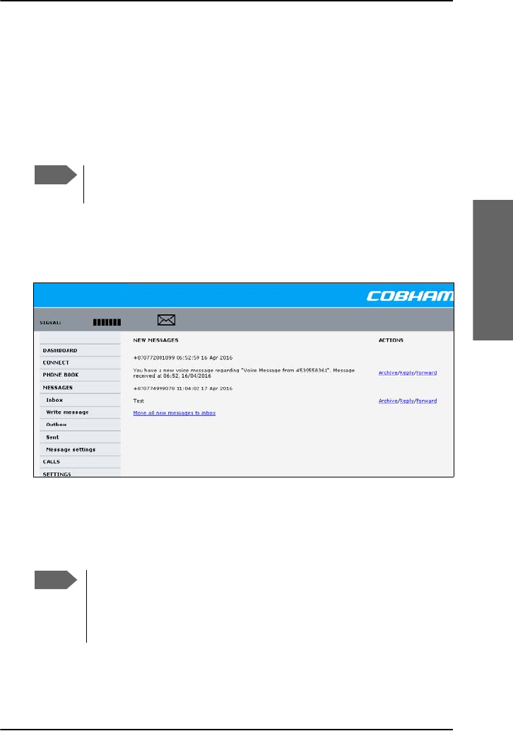
Chapter 3: Calls, faxes and SMS
SMS service 97
3333
Calls, faxes and SMS
+ <Mobile number>
The first part of the mobile number is always 870, which is the “country
code” for the BGAN system. If the mobile numbers are listed in the web
interface, you can look them up as follows:
Select PHONE BOOK > Mobile numbers. If the mobile numbers are not
listed in the web interface, refer to your service provider.
To receive a message
If a message has arrived, the icon bar at the top of the web interface shows
an unopened envelope. Click the envelope to see the new message(s).
Otherwise, to see new messages click MESSAGES from the left navigation
pane. The page shows new incoming messages.
The message icon disappears when all the messages on this page have been
archived or deleted.
Note
There are two Voice numbers, one for 3.1 kHz Audio and one for
Standard Voice.
Note
The system does not accept more than 100 incoming messages
(including read and unread messages). If you have received 100
messages, you have to delete some of them in order to free space
for new messages. Otherwise, the new messages are rejected.

Chapter 3: Calls, faxes and SMS
98 SMS service
If the message is not an SMS message but information of voice mail, call
your voice mail service number to hear the voice mail. The voice mail
number is displayed together with the message.
When using the voice mail service for the first time you must configure
your voice mailbox with your welcome greetings. Follow the instructions
given by the voice mail system.
To find your voice mail number, select MESSAGES > Message settings
from the left navigation pane and locate the Voice mail number.
Note that the voice mail number is only shown if it is available on the SIM
card. Otherwise, refer to the information from your service provider.
Options for new SMS messages
To see new messages, click MESSAGES from the left navigation pane.
Besides viewing the new messages, you have a number of options for what
to do with each message:
•Click Read to move it to your Inbox containing read messages.
•Click Reply to reply to a message.
Then type in your reply and click Send.
For information on how to include the original message in your reply,
see To set up the default message options on page 99.
•Click Forward to forward a message to someone.
Then type in the phone number in the Recipient field and click Send.
• If you want to move all the new messages, click Move all new
messages to Inbox.
Options for SMS messages in the Inbox
The messages in the Inbox are the incoming messages that have been
archives from the list of new messages. From the Inbox, you have the
following options:
•Click Reply to reply to a message.
Then type in your reply and click Send.
Note
New messages cannot be deleted until they have been
archived and moved to the Inbox.
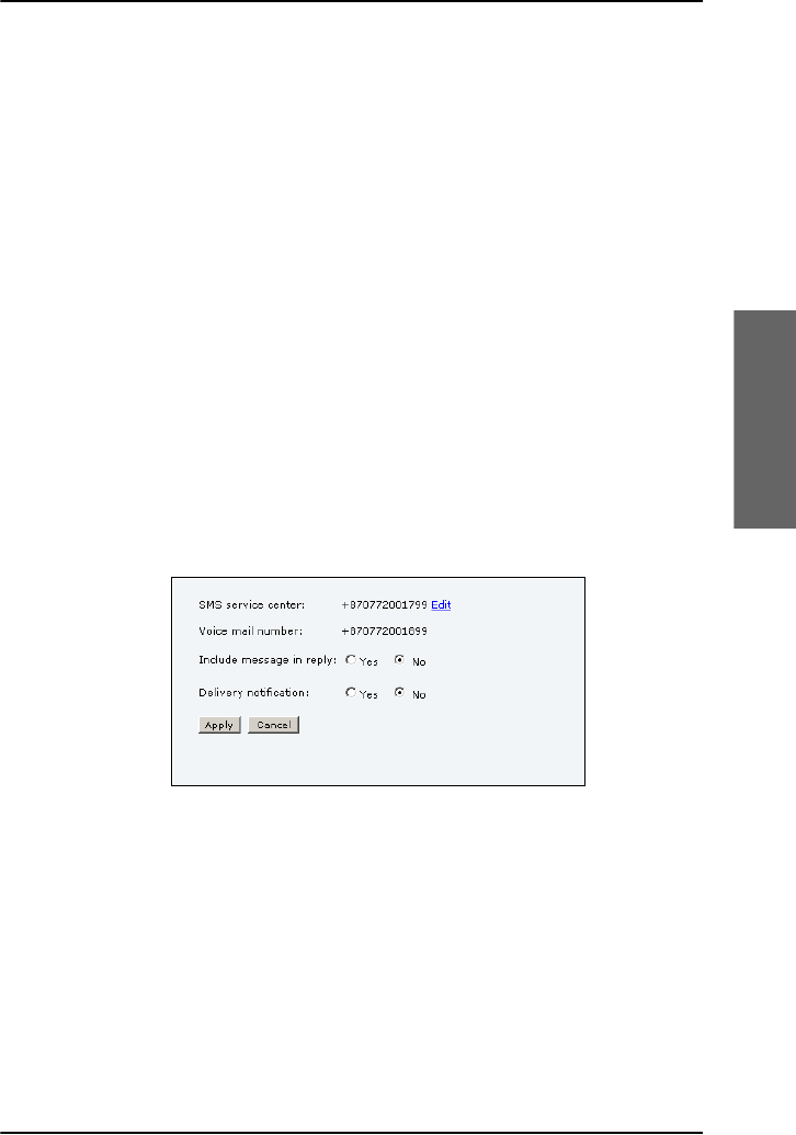
Chapter 3: Calls, faxes and SMS
SMS service 99
3333
Calls, faxes and SMS
For information on how to include the original message in your reply,
see To set up the default message options on page 99.
•Click Forward to forward a message to someone.
Then type in the phone number in the Recipient field and click Send.
•Click Delete to delete the message, or Delete all messages in Inbox
to delete all read messages in the Inbox.
Configure message settings
To set up the default message options
You can set up general options for outgoing messages. These settings apply
by default to all outgoing messages. Note, however, that you can change
the Delivery notification setting for an individual message. For further
information, see To send an SMS message on page 94.
To set-up the default message options do as follows:
1. Select MESSAGES > Message settings from the left navigation pane.
2. If you want to include the original message when you reply, select Yes
next to Include message in reply.
3. Select whether or not you want Delivery notification for SMS
messages.
If you click Yes, the Status column in the Sent folder will show the status
of your message when it has been sent.
4. Click Apply.

Chapter 3: Calls, faxes and SMS
100 SMS service
To view or change the SMS service center number
The SMS service center number identifies the SMS service center used
when sending and receiving SMS messages. The SMS service center is used
when you send a text message (SMS message) to another user. The
message is stored in the SMS service center which delivers it to the
destination user when they are available.
The SMS service center number is stored on the SIM card.
• To see the SMS service center number, select
MESSAGES > Message settings from the left navigation pane.
• To change the number, click Edit next to SMS service center, change
the number and click Save. Then click Apply to apply all changes in the
page.
The SMS service center number is provided from your service provider.
101
Chapter 4
4444
Use a computer
Use a computer 4
Use a computer over
SwiftBroadband
Selected scenarios
The application examples in this chapter are mainly based on the default
configuration and some typical application scenarios. If you have specific
requirements to the interface setup and configuration of your system refer
to the AVIATOR 700 Installation and maintenance manual.
Tool for setup and use: The web interface
Use the built-in web interface of the SwiftBroadband Unit (SBU) to access
the system settings. The web interface is accessed from a computer
connected to one of the LAN connectors or using the WLAN interface of
the SBU. The web interface is shown in an Internet browser. No additional
installation of software is needed.
In this manual you find information and instructions for the parts of the
web interface that you might need when using the system. The parts of the
web interface that deal with installation, configuration or maintenance are
described in detail in the AVIATOR 700 Installation and maintenance
manual.
Note
In the standard setup, data services are provided by
SwiftBroadband. This service is available exclusively on I4
satellites. For areas where there is no I4 coverage the AVIATOR
700 system can use Swift64 as a fallback solution for data
services.
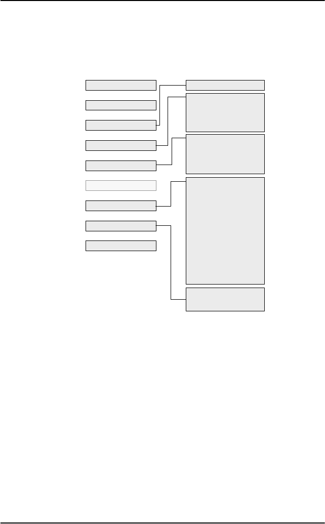
Chapter 4: Use a computer
102 Use a computer over SwiftBroadband
The following drawing shows the menus available in the web interface. The
topics in gray are mainly used during installation and maintenance of the
system, they are described in detail in the AVIATOR 700 Installation and
maintenance manual.
For more detailed information see Use the SBU web interface on page 164.
0RELOHQXPEHUV
,QER[
:ULWHPHVVDJH
2XWER[
6HQW
0HVVDJHVHWWLQJV
2XWJRLQJFDOOV
5HFHLYHGFDOOV
0LVVHGFDOOV
6WDQGDUGGDWDVHVVLRQV
6WUHDPLQJGDWDVHVVLRQV
&DOOFKDUJHV
/RJKDQGOLQJ
'DWDOLPLWV
3URILOHV
7UDIILFIORZILOWHUV
6,03,1
6,0/RFN
8VHUSHUPLVVLRQV
5HPRWHPDQDJHPHQW
/LQNPRQLWRULQJ
5HPRWHDFWLYDWLRQ
5HVWULFWHGGLDOLQJ
0XOWLYRLFH
'$6+%2$5'
&211(&7
3+21(%22.
0(66$*(6
&$//6
6(77,1*6
$'0,1,675$7,21
+(/3'(6.
6,7(0$3
(YHQWOLVW
(YHQWORJ
6HOIWHVW

Chapter 4: Use a computer
Use a computer over SwiftBroadband 103
4444
Use a computer
Services and interfaces
The following table shows the supported combinations of services and
interfaces, and which types of equipment can be used.
Service
Interface on the system
Phone/Fax
(RJ 11)
LAN (RJ 45) or
Wireless ISDN (RJ 45)
Circuit Switched
3.1 kHz
Audio
Analog
telephone
AVIATOR Wireless
Handset or other SIP-
enabled IP handset
ISDN telephone
G3 Fax
machine
G4 Fax machine
(If it supports G3 Fax)
Secure
telephone
STU/FNBDT
Standard
Voice
(AMBE)
Analog
telephone
AVIATOR Wireless
Handset or other SIP-
enabled IP handset
ISDN telephone
Data,
UDI or
RDIa
a. Check with your service provider that the RDI service is available on the Ground
Infrastructure network.
G4 fax machine or
computer with ISDN
modem
Packet Switched
Data
multi-
user
Computer or Smart
Phone
Data
single-
user
Computer or Smart
Phone
SMS Computer with web
interface

Chapter 4: Use a computer
104 Use a computer over SwiftBroadband
LAN and WLAN interfaces
If the Built-In Router option is activated you can connect several PCs and
other IP devices to the AVIATOR 700 system. Then the system operates as
a router. It handles IP data traffic so the AVIATOR 700 system can be used
with multiple computers for e-mail, Internet access, VPN, intranet and other
applications that use the packet switched connection.
If you have purchased the Wireless Option you can connect multiple
computers and other IP devices to the system via the Wireless Access
Point. For more information on these options see Built-in router and
Wireless options on page 8.
To connect a computer to the SBU you have several possibilities:
• Use one of the six LAN connectors (Ethernet) to connect user
computers or other LAN equipment. Check how many of the LAN
connectors are available in your installation and where to find them in
the cabin.
• If installed, use the Wireless Option to connect computers and other
devices using IP to the network.
There is also the front Maintenance connector on the front plate of the
SwiftBroadband Unit. This connector is typically not accessible during
flight. It is reserved for service and maintenance purposes.
Customize network use
With the built-in router functionality the AVIATOR 700 system offers a
flexible use of the data channel of the SwiftBroadband service. The system
administrator can configure the use of the data channel by defining
network user groups and profiles. The following picture gives an overview
over the parameters and functions involved.
MAC address
IP address
LAN port
Network
user
group
Primary
profile
Secondary
profile
Traffic flow
filters
Desired IP
connection

Chapter 4: Use a computer
Use a computer over SwiftBroadband 105
4444
Use a computer
An IP device that is connected to the AVIATOR 700 system will
automatically be assigned to the default network user group, if it is not
specified otherwise. The default setting of this group is a standard data
connection with automatic IP address allocation and automatic activation
of the connection.
The AVIATOR 700 system is flexible and can be configured to specific
requirements for your network use, e.g. manual activation of the Internet
connection, activating video streaming, a server on the network or a fixed
IP address on one of the devices. For this you need to set-up network
groups with specific primary and/or secondary profiles. You can find
detailed description in the AVIATOR 700 Installation and maintenance
manual.
Network user groups
To manage the use of the bandwidth and the applications allowed for the
individual user the system administrator can set up network user groups.
The following paragraphs describe how network user groups are used in the
AVIATOR 700 system.
When you connect an IP device (a computer, Smart Phone, etc.) to the SBU
the system will find out which network user group the device belongs to. To
do this the system uses the following information:
•The port the device is connected to, i.e. one of the 6 Ethernet ports,
Wireless or the SBU maintenance connector (reserved for service and
maintenance).
• The device’s IP address.
• The device’s MAC address.
In the default configuration of the network user group called DEFAULT
GROUP a specific IP address or the unit’s MAC address are typically not
needed. The DEFAULT GROUP uses the background IP data connection.
If you want to read more about how to customize the AVIATOR 700
system and how to set up network user groups and traffic profiles to meet
specific data traffic requirements see the AVIATOR 700 Installation and
maintenance manual.

Chapter 4: Use a computer
106 Use a computer over SwiftBroadband
Connect to the Internet
You can connect your PC or other IP devices e.g. your Smart Phone to the
Internet and use e-mail, VPN, file transfer applications etc. The following
sections describe two typical applications: Starting a standard data
connection and a streaming data connection.
Access the web interface in the AVIATOR 700 system
When the computer and the AVIATOR 700 system are ready you can
access the built-in web interface of the system to display various
information, use the SMS service or start and stop a data connection.
To check the connection of your computer to the web interface of the
system do as follows:
1. Power up your computer.
2. For LAN: Connect your LAN cable (standard Ethernet) between the
network connector on your computer and one of the LAN connectors
installed in the aircraft.
For WLAN: Check that the WLAN icon in the status bar of your
operating system indicates that the WLAN connection has been
established. If your WLAN is encrypted check with your system
administrator how to proceed to access the encrypted WLAN network.
3. Open your Internet browser and enter the default IP address of the
AVIATOR 700 system: http://192.168.0.1.
You may have to disable the Proxy server settings in your browser. For
further information, see Proxy server settings on page 165.
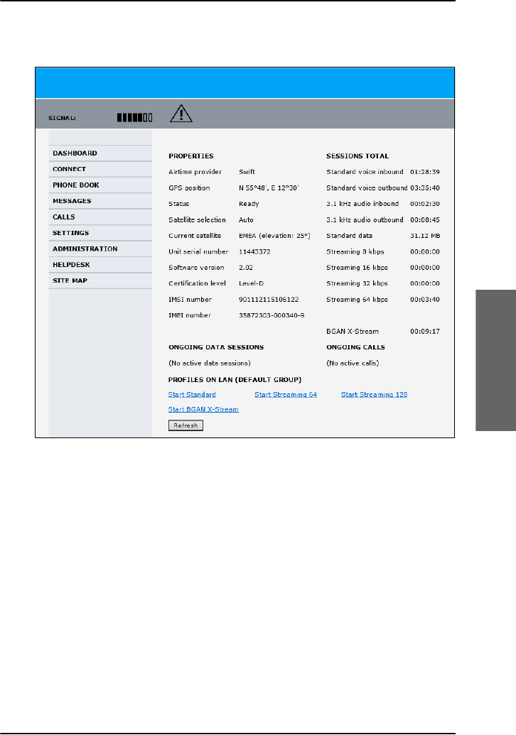
Chapter 4: Use a computer
Use a computer over SwiftBroadband 107
4444
Use a computer
4. The web interface opens and the page DASHBOARD is displayed. On
the Dashboard you see the current system information.
You can configure the AVIATOR 700 system to your specific requirements.
This is typically done during the installation and initial setup of the system.
See the AVIATOR 700 Installation and maintenance manual for detailed
information how to customize the interfaces of the system and how to set
up network user groups and profiles to manage data traffic and bandwidth
usage.
Unintended use of bandwidth
The system default setting is automatic activation of a standard data
connection. With this setup you connect the PC to the cabin network and
start using the applications. You do not have to connect to the web
interface to start using the services, it is plug-and-play. This setting involves
a high risk of being charged for airtime and bandwidth when connected
computers perform automatic software updates. These updates are not

Chapter 4: Use a computer
108 Use a computer over SwiftBroadband
limited to the Windows system itself, but also other installed programs ( e.g.
browsers, Java and Media or Flash players) might do updates. Some do
updates even without prompting before the download is complete.
To avoid unintended use of bandwidth through automated background
services the system can be set to not automatically connect to the Internet
when you connect your computer or other IP equipment (PDA,
smartphone, webcam, etc.) to the network interface. You set this in the web
interface.
However, selecting manual activation alone will not prevent these updates,
but only delay them until the connection is activated. The only way to be
sure is to disable updates in all programs, which can be a difficult task.
Please check with you IT department for assistance on this. If you want to
start a data connection in this mode you must access the system’s web
interface and activate your data session, standard IP and/or streaming IP,
from the Dashboard.
Understand Standard and Streaming data connections
The BGAN network
supports different
types of IP data
connections to the
Internet. There is
Standard data and
Streaming data. The
figures on this page
show how the bandwidth of 432 kbps with a high-gain antenna is used
Note
Online software updates of the connected devices (PC,
smartphone etc.) should only be performed when you are
connected at the office or at home where bandwidth and airtime
are less costly. Check the documentation for the device how to
disable automatic software updates.
Note
Optimize airtime and bandwidth usage: You are charged for
the bandwidth used for automatic software updates. We
recommend to disable this feature in your computer.
Standard IP
connection Standard IP
connection
Streaming IP
connection
128 kbps
Up to 432 kbps
total data
rate
Up to 432 kbps
total data
rate

Chapter 4: Use a computer
Use a computer over SwiftBroadband 109
4444
Use a computer
when set-up as Standard connection (left) and as Standard and Streaming
128 kbps (right).
•Standard data connection: All users that have signed on the network
share the bandwidth available. This type of connection is ideal for
TCP/IP traffic such as e-mail, file transfer, and Internet and intranet
access. Standard data services are charged by the volume of data
transferred.
•Streaming data connection: You get a guaranteed, high-priority
connection, ensuring seamless transfer of data with guaranteed bit rate
and Quality of Service. This type of connection is ideal for time-critical
applications like live video over IP. Streaming classes are charged by the
time the service is being used (per minute charge).
The system administrator can set up various types of connections using
network user groups, profiles and traffic flow filters. For information on this
see the AVIATOR 700 Installation and maintenance manual.
Data sessions available for the current user are displayed under PROFILES
ON LAN or STREAMING PROFILES ON LAN at the bottom of the
Dashboard.
The AVIATOR 700 system supports the use of network user groups. These
network user groups define which type of IP connections are allowed for
each group. Each network user group has then one or more profiles for
various applications. You can only see, start and stop profiles of the network
user group you belong to.
Note
You must always close the Streaming connection manually to
finish the connection properly. You must click Stop
streaming in the web interface to close the streaming
connection. It is not enough to disconnect the equipment. As
long as the connection is active you are charged for the
service.
Note
The system administrator can start and stop data sessions for all
network user groups, see also Start or stop any data session on
page 179.
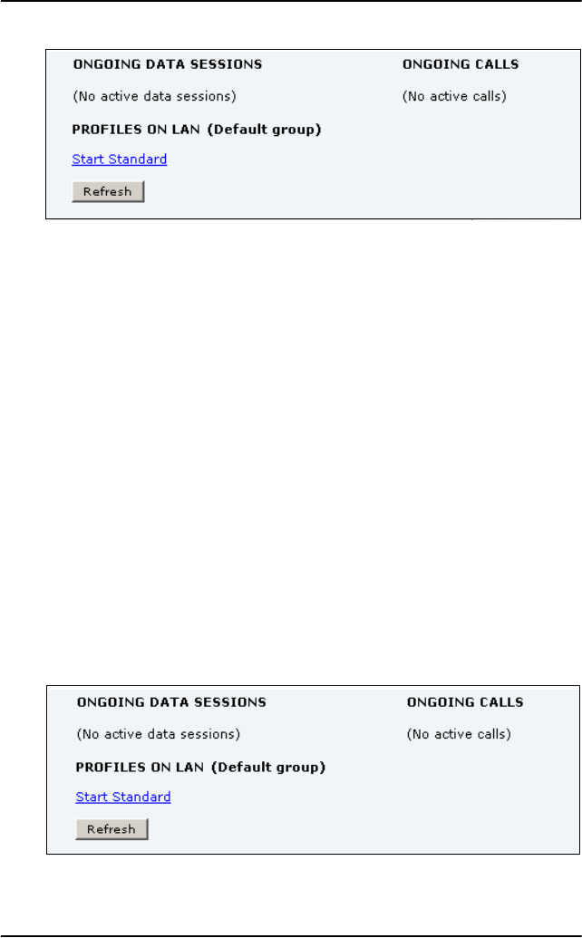
Chapter 4: Use a computer
110 Use a computer over SwiftBroadband
• Primary profiles are listed in the left side and secondary profiles (if any)
are listed to the right.
• Profiles that are currently active are displayed as a link with the text
“Stop <name of profile>”.
• Profiles that are ready to be activated are displayed as a link with the
text “Start <name of profile>”.
Start or stop a Standard connection
On the Dashboard you can see under PROFILES ON LAN whether a standard
connection is active or not. To start or stop a Standard connection for your
Network user group do as follows:
1. Open your Internet browser and enter the IP address of the AVIATOR
700 system (default: http://192.168.0.1) to access the Dashboard of the
web interface.
2. Locate PROFILES ON LAN at the bottom of the page.
3. Click Start <name of profile>, in this case: Start Standard, or Stop
<name of profile> to stop the connection.
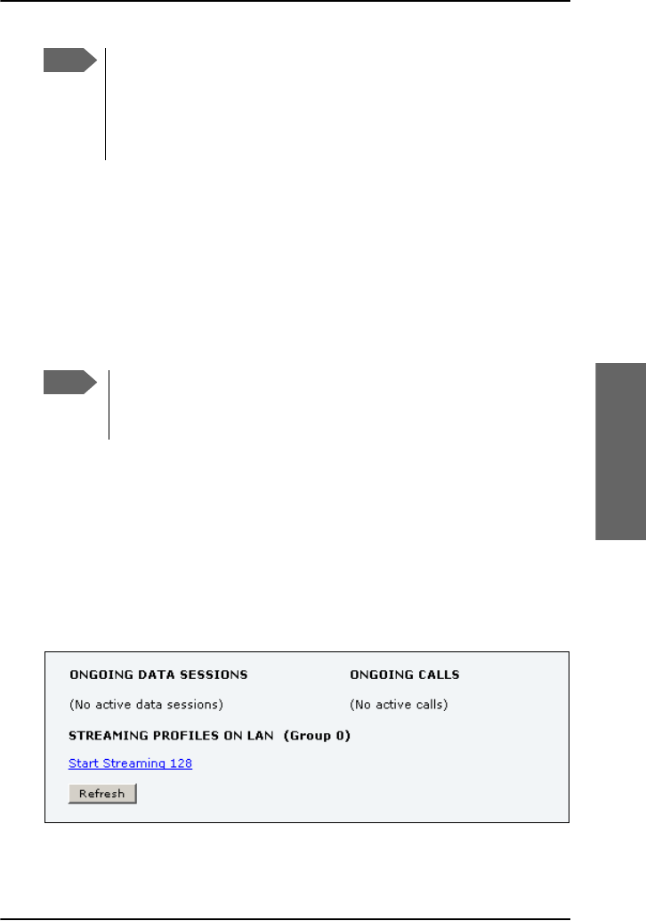
Chapter 4: Use a computer
Use a computer over SwiftBroadband 111
4444
Use a computer
Start or stop a Streaming connection
The AVIATOR 700 system supports 8, 16, 32, 64 and 128 kbps streaming
classes. Note that streaming classes are charged by the time the service is
being used (per minute charge). A started Streaming session will stay active
until you manually stop it. On the Dashboard you can see whether the
network user group you belong to has been set up to support streaming
sessions.
To start or stop a Streaming session do as follows:
1. Open your Internet browser and enter the IP address of the AVIATOR
700 system (default: http://192.168.0.1) to access the Dashboard of the
web interface.
2. Locate STREAMING PROFILES ON LAN.
3. Click the link with the name of the Streaming profile that has been set
up for you.
Note
If a primary profile is already active, your new profile will not
appear as a link but as plain text. The active primary profile is
displayed as a link with the text “Stop <name of profile>”. Click this
link first to stop the active profile. Then click your new profile,
which is now displayed as a link, to start your new profile.
Note
You can only start a Streaming session if the administrator has set
up a Streaming profile for your user group. Contact your system
administrator if you need a streaming connection.

Chapter 4: Use a computer
112 Use a computer over Swift64
Always manual activation of a Streaming connection
The streaming data connection cannot automatically be activated, you
must start it manually in the web interface. This is a safety measure to
prevent the system from unintended use of bandwidth. A started Streaming
session will stay active until you manually stop it in the web interface.
Use a computer over Swift64
For detailed instruction how to set-up an ISDN or MPDS connection, an
analogue modem connection and make a dial-up connection to the
network see Swift64 and H+ Data Service, Supplement to AVIATOR 700
and HSD+ User Manual, available for download. (Order number: 98-
130578)
Note
If a primary profile is already active, your new profile will not
appear as a link but as plain text. The active primary profile is
displayed as a link with the text “Stop <name of profile>”. Click this
link first to stop the active profile. Then click your new profile,
which is now displayed as a link, to start your new profile.
Important
If you have selected and started a Streaming connection as
your primary profile, the LAN or WLAN interface will be
running a Streaming connection until you stop it. It is not
enough to disconnect the equipment from the interface.
Note
ISDN and MPDS services are only available when the aircraft is
positioned inside an area with Spot Beam coverage (for regions
with I3 coverage).

113
Chapter 5
5555
System operation
System operation 5
In this chapter
In this chapter you can read about:
•Full Feature handset operation (SDU)
•MCDU operation
•Use the SBU web interface
Full Feature handset operation (SDU)
This section describes how to access the menu system using the keys and
display of the Full Feature handset.
•Use the SDU phone book
•Handset Setup
•Ring Profile
•Lock System
•Logon Menu
•System Setup
•Status
•Maintenance (reset)
For an overview of all the menus, see Menu trees on page 211.

Chapter 5: System operation
114 Full Feature handset operation (SDU)
Access and exit menus
•To access the menus, press C or GJ.
When you are in the menu system you may also press GJ to reach
the top level of the menus.
•To scroll through the menus, use the B and E keys.
•To enter the selected menu, press C.
•To go back to the previous level in the menu system, press A.
•To exit the menu system completely from anywhere in the menu
system, press GA.
•To reach a specific item in the menu system, press GJ and a
number corresponding to the entry level.
Example: Press GJN to access the 'Logon' menu (which is
the 5th entry in the main menu).
Restricted access
There are 4 different levels of access to the menus:
•Users without a PIN code.
If the handset is locked with the Normal User PIN code, the only
function available is answering the phone. If the Normal User PIN code
is disabled, all Normal User functions are available.
•Normal User
The Normal User has access to normal everyday functions and to make
changes to these.
• Super User
The Super User has the same rights as the Normal User, but can
additionally access a few extra settings that are not available to the
Normal User.
• Service Provider
The functions restricted by the Service Provider PIN code can only be
accessed by the supplier or Cobham SATCOM.

Chapter 5: System operation
Full Feature handset operation (SDU) 115
5555
System operation
You will be prompted for a PIN code when entering a function that is
restricted by PIN codes. See more about setting PIN codes at System
Setup, Pin Setup on page 136.
Use the SDU phone book
The Phone Book can contain up to 99 entries, which can be used for
making phone calls. You can edit, delete or insert entries.
To access the Phone Book menu, you can:
• press B or E from the main display, or
• press C to enter the main menu, scroll to Phone Book and press
C.
Each entry holds the following information:
•Name
• Telephone number
The telephone number must include call prefix for automatic calls and
international access code. The telephone number can hold up to 22 digits.
The name can hold up to 24 characters.
The list of entries in the phone book is sorted alphabetically.
An entry in the phone book is displayed as a name if in alpha mode or as a
telephone number if in normal mode. Note that only the first 12 digits are
displayed.
Enter name Enter number
Call selected number
DeleteEntry?
<Entry > Entry is deleted
Edit / Ins
Del
ABC Toggle display between
name and number
Scroll between
phone numbers
OK
OK
OK
OK
Phone Book
HandsetSetup
Ring Profile
Lock System
Logon Menu
System Setup
Status
Maintenance

Chapter 5: System operation
116 Full Feature handset operation (SDU)
To make a call using the phone book
Do as Follows:
1. Within the phone book, use BE to select an entry.
2. Press C, I or U to dial.
Hint: You may also go directly to a specific entry by pressing the key
holding the first letter of the entry.
Example: To find an entry with the name Jones, press N once. To find
an entry with the name Larsen, press N three times.
To insert a new entry in the phone book
Do as follows:
1. From within the phone book, press GD.
2. Enter the name of the new entry followed by C.
3. Enter the phone number including country code and press C.
Example: In this example the number to Cobham SATCOM VA,
00 1 757 463 9557, is inserted:
GD
THRANEC
00 1 757 463 9557 C
To delete an entry in the phone book
1. Select the entry in the phone book.
2. Press GF.
To edit an entry in the phone book
Do as follows:
1. Select the entry in the phone book.

Chapter 5: System operation
Full Feature handset operation (SDU) 117
5555
System operation
2. Press GB and type in the new name followed by C. Then type in
the new number followed by C.
Handset Setup
Overview
The HandsetSetup menu is used for adjusting the light and sound
settings of the handset.
The HandsetSetup menu has the following submenus:
•Silent
•Contrast
•Light
• Key Beep
• Single Ring
• Common Ring
•Ring Volume
•Phone Volume
•ComfortNoise
Each of the submenus is described in the following pages.
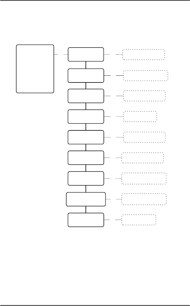
Chapter 5: System operation
118 Full Feature handset operation (SDU)
The Handset Setup menu
To access the HandsetSetup menu, enter the main menu, scroll down
to HandsetSetup and press C.
Scroll between 1 to 8 *
Scroll between Auto,
On, Off and All off
Scroll between
Off and 1 to 4 *
Scroll between 8
predefined ringtones
Scroll between 8
predefined ringtones
Scroll between 1 to 4 *
Scroll between
Off and 1 to 3 *
Phone Book
HandsetSetup
Ring Profile
Lock System
Logon Menu
System Setup
Status
Maintenance
Toggle between
Enabled and Disabled
Scroll between 1 to 8 *
OK
Contrast
Light
Key Beep
Single Ring
Common Ring
Ring Volume
ComfortNoise
Silent
Phone Volume
OK
OK
OK
OK
OK
OK
OK
OK
OK

Chapter 5: System operation
Full Feature handset operation (SDU) 119
5555
System operation
To enable/disable the Silent function
Select Silent to view or change the Silent setting of the handset.
Use B and E to toggle between Enabled and Disabled.
Enabled turns off the ring tone of the handset.
To adjust the LCD contrast
Select Contrast to view or change the contrast setting of the handset
display.
Use B and E to adjust the contrast and C to confirm.
The value can be between * and ********.
To change the light settings
Select Light to view or change the light settings of the handsets.
Use B and E to scroll between the settings and C to confirm.
The value can be Auto | On | Off | All Off.
The following table shows the function of the light settings.
Setting Display Backlight LEDs
Auto Activated on event Normal function
On Always on Normal function
Off Always off Normal function
All Off Always off Always off

Chapter 5: System operation
120 Full Feature handset operation (SDU)
To adjust the key beep volume
Key beep is a “beep” sound when a key is pressed.
Select Key Beep to view or change the key beep setting of the
handsets.
Use B and E to adjust the volume of the key beep and C to
confirm.
The value can be Off or between * and ****.
To select the ring tone for a direct call
Single Ring is the ring tone for a direct call (opposite to a broadcast call).
Select Single Ring to view or change the direct ring tone setting of
the current handset.
Use B and E to scroll through the ring tones and C to select.
You can choose between 8 predefined ring tones.
To select the ring tone for broadcast calls
Common Ring is the ring tone for broadcast calls.
Select Common Ring to view or change the broadcast ring tone setting
of the current handset.
Use B and E to scroll through the ring tones and C to select.
You can choose between 8 predefined ring tones.

Chapter 5: System operation
Full Feature handset operation (SDU) 121
5555
System operation
To adjust the ring volume
Select Ring Volume to view or change the Ring Volume setting of the
handset.
Use B and E to adjust the Ring Volume and C to confirm.
The value can be between * and ****.
To adjust the phone volume
Select Phone Volume to view or change the initial volume setting for
the handset. To adjust the volume during a call, use the volume control on
the side of the handset.
Use B and E to adjust the Phone Volume and C to confirm.
The value can be between * and ********.
To adjust the Comfort Noise
Comfort Noise is a background noise to verify that the line is connected.
Select ComfortNoise to view or change the Comfort Noise setting of
the handset.
Use B and E to adjust the Comfort Noise and C to confirm.
The value can be Off or between * and ***.

Chapter 5: System operation
122 Full Feature handset operation (SDU)
Ring Profile
Overview
The Ring Profile menu allows you to select from a list of ring
profiles. A ring profile applies to the entire system and determines the ring
settings of each unit in the system.
To select a Ring Profile
Do as follows:
1. To access the Ring Profile menu, enter the main menu, scroll
down to Ring Profile and press C.
2. Use B and E to scroll through the ring profiles and C to select.
For information on how to change the ring profiles, see the section System
Setup, Ring Profiles on page 133.
Note
If the “Chime/Lamps Inhibit” function is used in the installation,
the “TakeOfLandng” profile is automatically activated during
takeoff and landing.

Chapter 5: System operation
Full Feature handset operation (SDU) 123
5555
System operation
Lock System
Overview
The Lock System menu can be used to lock the phone. When the
phone is locked, you can still answer an incoming call, but you cannot
access any of the functions until you press C and enter the Normal User
PIN code.
To lock the handset
Do as follows:
• To lock the phone, enter the main menu, scroll down to Lock
System, press C and enter the Normal User PIN code.
• To unlock the phone, press C and enter the Normal User PIN code.
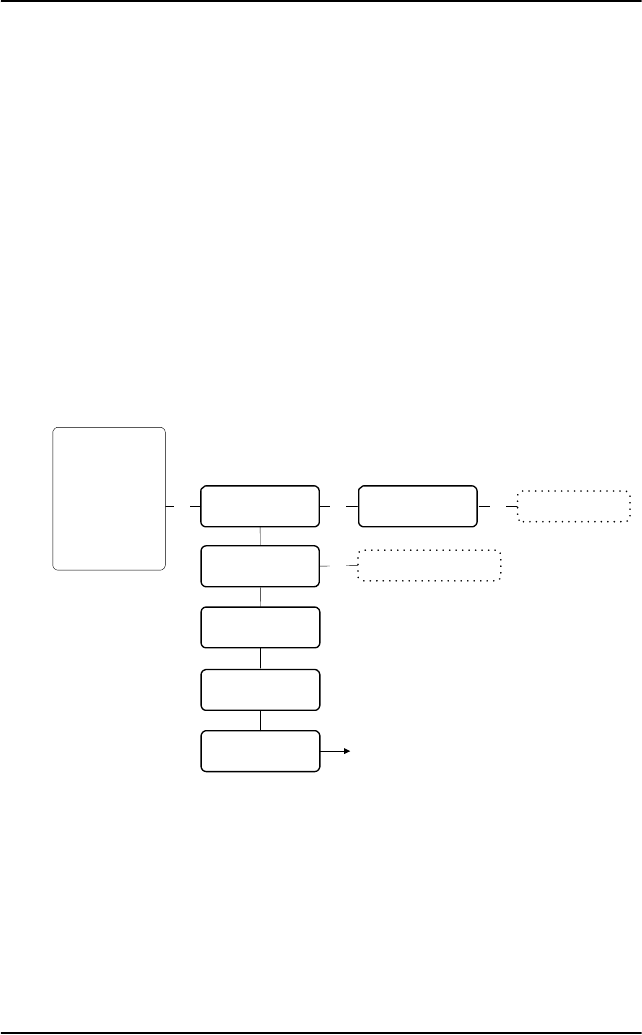
Chapter 5: System operation
124 Full Feature handset operation (SDU)
Logon Menu
The Logon Menu is used to log on or off the system, or to change the
Logon settings.
The Logon Menu has the following sub menus:
•Manual Logon
•Custom Logon
•Auto Logon
•Logoff
•Settings (see Logon menu settings on page 126)
To access the Logon Menu, enter the main menu, scroll down to Logon
Menu and press C.
OK
Custom Logon
Auto Logon
Logoff
Settings
Manual Logon
OK
OK
Enter Sat-ID and GES-ID
See Settings submenu
Phone Book
HandsetSetup
Ring Profile
Lock System
Logon Menu
System Setup
Status
Maintenance
I4: H+ SBB
I3: H+ SW64 OK Scroll through the
list of known GESs
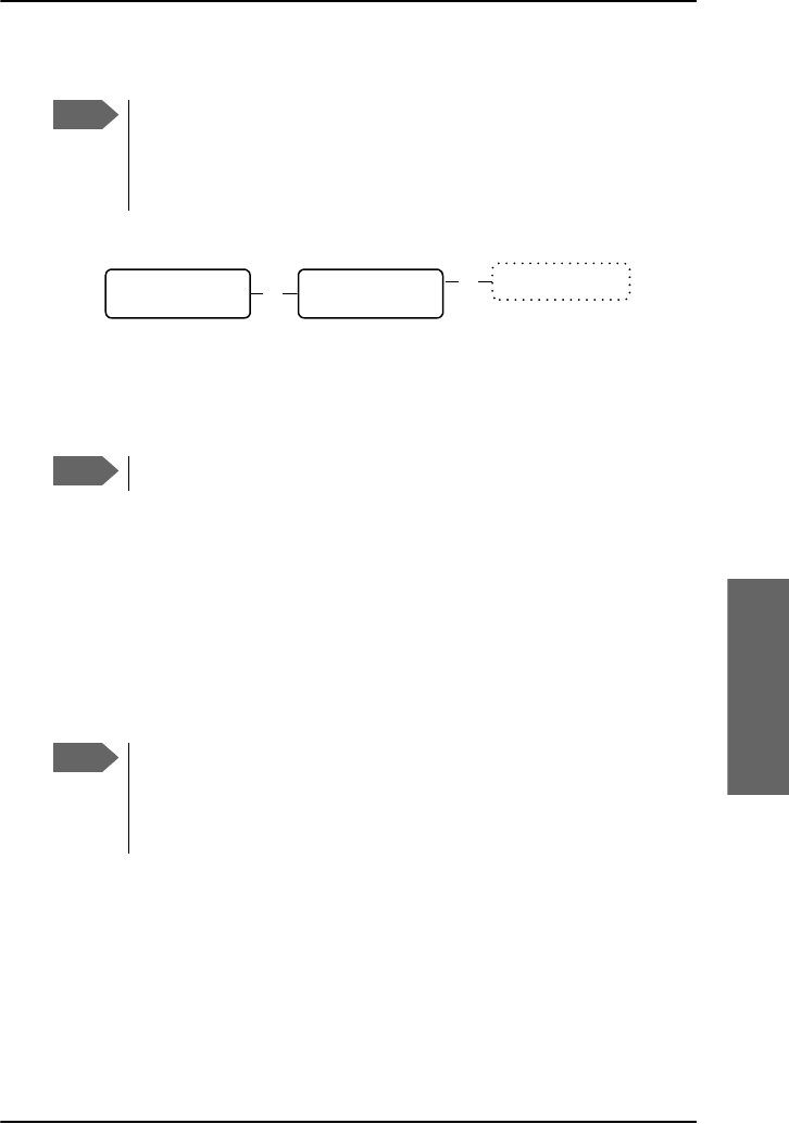
Chapter 5: System operation
Full Feature handset operation (SDU) 125
5555
System operation
To log on manually
Select the satellite and the services
• I4 satellite offers the services Classic Aero (H+) and SwiftBroadband
(SBB)
• I3 satellite offers the services Classic Aero (H+) and Swift64
(SW64/HSD) services.
1. Select Manual Logon to select the satellite type you want to logon
to: I3 or I4. Use B and E to scroll through the list and C to
select.
2. Select the GES from the list of known GESs. Use B and E to scroll
through the list and C to select.
To make a custom logon
You can use this menu if you need to log on to a GES which is not in the list
of known GESs.
1. Select Custom Logon to manually enter the Sat-ID and GES-ID you
want to use for logging on.
For a list of supported GESs, see List of available GESs on page 215.
2. Enter the Sat-ID and GES-ID and press C to confirm.
Note
Before logging on manually, make sure the Logon Policy is set to
Manual. To change the Logon Policy, select Settings from the
Logon Menu and then Logon Policy. You can toggle between
Manual and Automatic and select with C.
Note
In most cases the I4 satellite is used.
OK
Manual Logon I3: H+, SW64
I4: H+, SBB OK Scroll through the
list of known GESs
Note
Before making a Custom Logon, make sure the Logon Policy is set
to Manual. To change the Logon Policy, select Settings from the
Logon Menu and then Logon Policy. You can toggle between
Manual and Automatic and select with C.

Chapter 5: System operation
126 Full Feature handset operation (SDU)
To select automatic logon
Select Auto Logon to log on automatically to the most appropriate
GES.
To log off
Select Logoff to log off the system.
To log on again you have to use the logon menu.
Logon menu settings
From the Settings submenu you can change the logon policy and
view or change the lists of preferred GESs and LESs.
The Settings menu has the following sub menus:
•Logon Policy
•Pref. H+GES
• Pref. ISDN LES
•Pref. MPDS LES
Each of the submenus is described in the following pages.
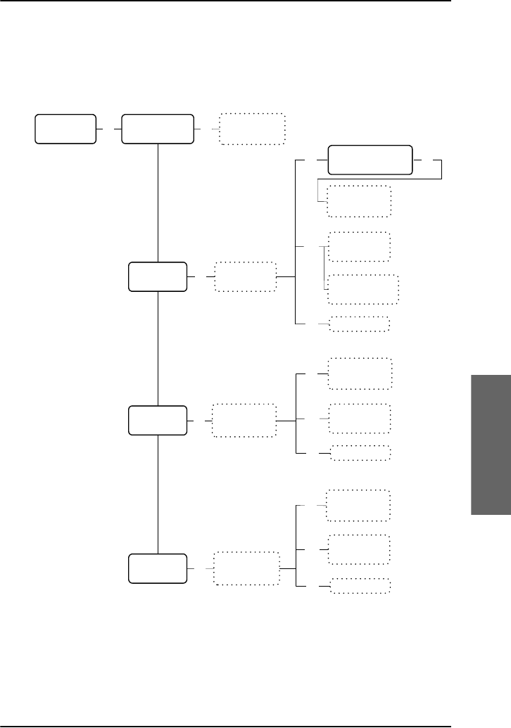
Chapter 5: System operation
Full Feature handset operation (SDU) 127
5555
System operation
The Settings submenu
To access the Settings submenu, enter the Logon Menu, scroll
down to Settings and press C.
Settings OK Logon Policy
H+ GES
ISDN LES
MPDS LES
Toggle between
Automatic and
Manual
OK Scroll through
list of
preferred GESs
OK Scroll through
list of preferred
LESs for ISDN
OK
Scroll through
list of preferred
LESs for MPDS
OK
Scroll and
select from list
of known GESs
Ins
Del
GES is deleted
Use up/down
keys to change
priority
Edit
Scroll and
select from list
of known LESs
Ins
Del LES is deleted
Use up/down
keys to change
priority
Edit
Scroll and
select from list
of known LESs
Ins
Del LES is deleted
Use up/down
keys to change
priority
Edit
Use * key to set
the same priority
as GES below
I4: H+ SBB
I3: H+ SW64 OK

Chapter 5: System operation
128 Full Feature handset operation (SDU)
To select the Logon Policy
Select Logon Policy to display or change the logon policy.
Use B and E to toggle between Automatic and Manual.
•Automatic: The system automatically logs on when it is powered.
•Manual: When the system is powered, you have to enter the Logon
menu to log on to the system.
To modify the list of Preferred GESs
Select H+ GES to view or change the list of preferred GESs for H+
transmission.
The H+ GES list is a list of the preferred GES operators to use as gateway to
the terrestrial network.
Do as follows:
•To add a GES to the list, press GD, scroll through the list of known
GESs and use C to select the GES you want to add.
•To delete a GES from the list, scroll to the GES you want to delete and
press GF.
•To change the priority of a GES, scroll to the GES you want to change
and press GB. Use B or E to move the GES to the right
priority and press C.
•To assign the same priority to two GESs, scroll to the GES you want
to change (GES 1)and press GB.
Using B or E, move GES 1 next to the GES with the priority you
want (GES 2), so that they are both visible in the display.
Then press S. The two GESs should now both have the priority of GES
2.
Note
The list of preferred GESs is typically selected during system
installation. If the GES list is empty, the system will automatically
select the most suited satellite and a random GES.
Note
Priority no. 1 is the highest priority!

Chapter 5: System operation
Full Feature handset operation (SDU) 129
5555
System operation
To modify the list of Preferred ISDN LESs
Select ISDN LES to view or change the list of preferred LESs for ISDN
transmission. The ISDN LES list is a list of the LES operators that are
preferred as gateway for ISDN traffic to/from the terrestrial network.
•To add a LES to the list, press GD, scroll through the list of known
LESs and use C to select the LES you want to add.
•To delete a LES from the list, scroll to the LES you want to delete and
press GF.
•To change the priority of a LES, scroll to the LES you want to change
and press GB.
Use B or E to move the LES to the right priority and press C.
To modify the list of Preferred MPDS LESs
Select MPDS LES to view or change the list of preferred LESs for MPDS
transmission. The MPDS LES list is a list of the LES operators that are
preferred as gateway for MPDS traffic to/from the terrestrial network.
•To add a LES to the list, press GD, scroll through the list of known
LESs and use C to select the LES you want to add.
•To delete a LES from the list, scroll to the LES you want to delete and
press GF.
•To change the priority of a LES, scroll to the LES you want to change
and press GB. Then use B or E to move the LES to the right
priority and press C.
Note
The list must include one LES as a minimum. One LES covers all
ocean regions.
Note
Priority no. 1 is the highest priority!
Note
The list must include one LES as a minimum. One LES covers all
ocean regions.

Chapter 5: System operation
130 Full Feature handset operation (SDU)
System Setup
The System Setup menu is used for viewing and changing system
parameters such as ring profiles, PIN codes etc.
The System Setup menu has the following submenus:
•Ring Profiles (see System Setup, Ring Profiles on page 133)
•QuickDial (see System Setup, Quick Dial on page 135)
• Disclose Pos
• Fax Setup
•Pin Setup (see System Setup, Pin Setup on page 136)
•Configure (see System Setup, Configure on page 138)
Each of the submenus is described on the following pages.
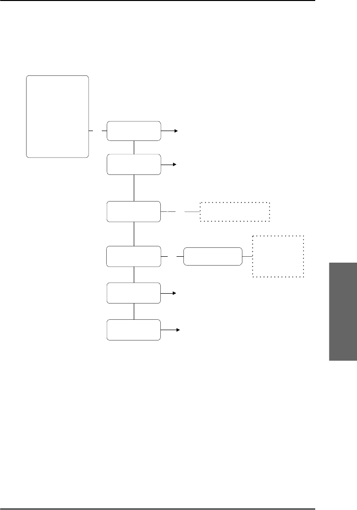
Chapter 5: System operation
Full Feature handset operation (SDU) 131
5555
System operation
The System Setup menu
To access the System Setup menu, enter the main menu, scroll down
to System Setup and press C.
Toggle between
Enabled and Disabled
RingProfiles
OK
OK
See RingProfiles submenu
See QuickDial submenu
See Pin Setup submenu
See Configure submenu
QuickDial
Disclose Pos
Pin Setup
Configure
Phone Book
HandsetSetup
Ring Profile
Lock System
Logon Menu
System Setup
Status
Maintenance
Fax Setup OK Fax Interface
Scroll between
Not Connected,
POTS #5,
POTS #6 and
POTS #5 & #6

Chapter 5: System operation
132 Full Feature handset operation (SDU)
To enable/disable disclosure of the aircraft position
Select Disclose Pos to view or change the Disclose Position status.
Use B and E to toggle between Enabled and Disabled.
• If you select Enabled, the position of the aircraft will be disclosed to
the earth station for use in the Inmarsat network.
• If you select Disabled, only the ID of the current spot beam is
disclosed.
To turn off the broadcast ring tone for an interface
Select Fax setup to determine which interface should not ring on a
broadcast call.
Use B and E to scroll through the interface options and select with
C.
You may select:
•POTS #5
•POTS #6
• POTS #5 & #6, or
•Not Connected
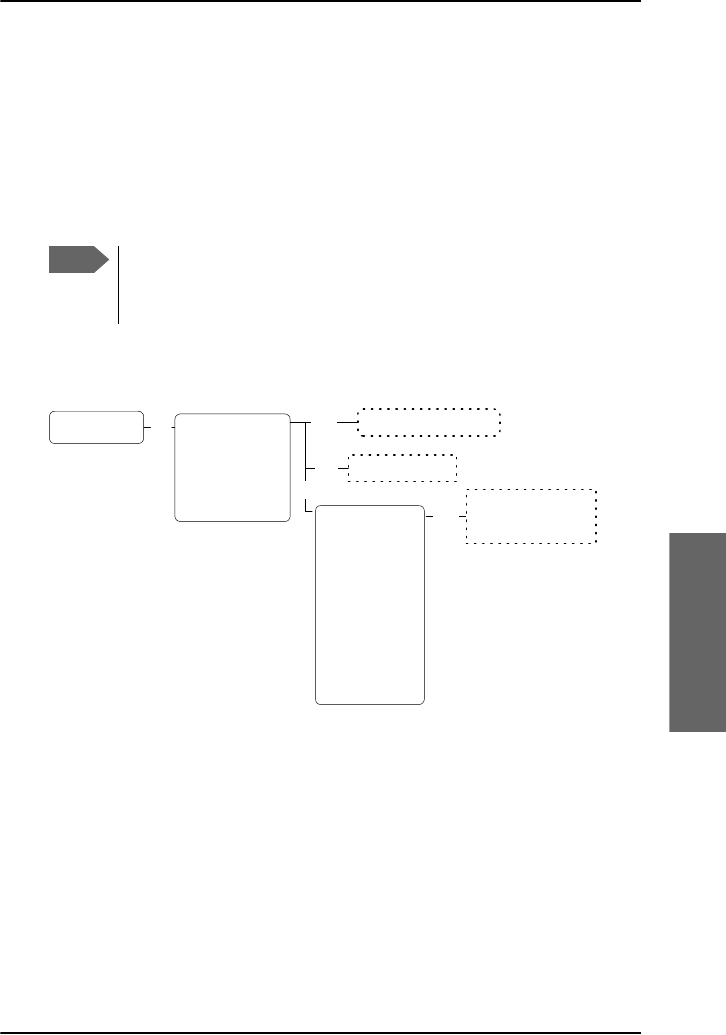
Chapter 5: System operation
Full Feature handset operation (SDU) 133
5555
System operation
System Setup, Ring Profiles
The RingProfiles submenu is used to view or change the Ring
Profiles of the system. A ring profile applies to the entire system and
determines the ring settings of each unit in the system.
You can have up to 5 ring profiles. The name of one of the profiles,
“TakeOfLandng”, is predefined and cannot be changed.
To access the RingProfiles submenu, enter the System Setup
menu, scroll down to RingProfiles and press C.
Note
If the “Chime/Lamps Inhibit” function is used in the installation,
the “TakeOfLandng” profile is automatically activated during
takeoff and landing.
OK
Edit Scroll between "User
control", "Ringer on"
and "Ringer off"
Enter new Profile name
RingProfiles 1 <empty>
2 <empty>
3 <empty>
4 <empty>
TakeOfLandng
Edit
Handset #1
Handset #2
Handset #3
Handset #4
POTS #1
POTS #2
ISDN
Annunciator1
Annunciator2
Annunciator3
OK
Entry is deleted
Del

Chapter 5: System operation
134 Full Feature handset operation (SDU)
To change the name of a profile
Do as follows:
1. Scroll to the profile.
2. Press GB.
3. Type in the new name and press C.
To change the contents of a profile
Do as follows:
1. Select the profile using C.
2. Scroll to the device you want to change the settings for, and select it
with C.
3. Use B and E to toggle between User Control, Ringer On
and Ringer Off.
To delete a profile
Do as follows:
1. Scroll to the profile you want to delete.
2. Press GF.
Note
“User Control” is only applicable to Handset #1 through #4.
This means you can configure each of the handsets #1
through #4 separately. For the remaining devices, “User
Control” has the same function as “Ringer On”.

Chapter 5: System operation
Full Feature handset operation (SDU) 135
5555
System operation
Explanation of the annunciators
•Annunciator #1 (Call Annunciator): This Annunciator is used for
signalling incoming voice calls. The Annunciator is “flashing” like the
Connection LED on a Full Feature handset and is turned off when the
call is answered or terminated by initiator.
•Annunciator #2 (Fax Annunciator): This Annunciator is used for
signalling incoming faxes. The Annunciator is “steady ON” until a receipt
for the fax has been given in the handset.
•Annunciator #3 (Service Annunciator): This Annunciator is used for
indicating service availability. The Annunciator is “steady ON” when H+
service is available.
System Setup, Quick Dial
Overview
The QuickDial submenu is a list of 1-digit numbers for quick dialling of
up to 9 favorite phone numbers.
To access the QuickDial submenu, enter the System Setup
menu, scroll down to QuickDial and press C.
To delete a Quick Dial entry
Do as follows:
1. Scroll to the quick dial number you want to delete.
2. Press GF.
Scroll between All
Phone book entries
Delete entry
Del
QuickDial 1 <empty>
2 <empty>
3 <empty>
4 <empty>
5 <empty>
6 <empty>
7 <empty>
8 <empty>
9 <empty>
OK Edit

Chapter 5: System operation
136 Full Feature handset operation (SDU)
To edit a Quick Dial entry
Do as follows:
1. Scroll to the quick dial number you want to change and press GB.
2. Scroll through the phone book to the phone number you want to use
with the selected quick dial number.
3. Press C to select the phone number.
System Setup, Pin Setup
PIN codes for the full-feature handset
For some of the functionality, access to the full-feature handset is
restricted by a PIN code. Three different kinds of user PIN codes are used in
the satcom system:
For all PIN code types the length must be between 4 and 8 digits. For
further information how to change and disable PIN codes see System
Setup, Pin Setup on page 136.
Use the Pin Setup submenu to disable or change PIN codes.
PIN code Functionality
Normal User The normal everyday user can make and receive calls,
access the phone book, choose an ocean region and a
default LES and GES, and read the error log and status.
Super User The Super User has the same rights as the Normal User.
In addition, the Super User can access certain super
user functions. A Super User will typically be a person
responsible for setting up and maintaining the system.
Service Provider The Service Provider has access to all functionality
accessible through the Full Feature handset.
Only Cobham SATCOM and/or the supplier of the
equipment normally know this PIN code.

Chapter 5: System operation
Full Feature handset operation (SDU) 137
5555
System operation
To access the Pin Setup submenu, enter the System Setup menu,
scroll down to Pin Setup and press C.
To access the PIN codes
To access the PIN codes you want to change or disable, do as follows:
1. Scroll to the PIN code type you want to change or disable.
2. Enter the current PIN code for the selected type.
3. Toggle between Change Pin and Disable Pin and use C to
select the function.
•Change Pin: Choosing Change Pin you will be prompted for
a new PIN code. Enter a new PIN code of 4 to 8 digits and use C
to accept the code. When you are prompted to re-enter the PIN
code, enter the code again and accept with C.
•Disable Pin: Select Disable Pin to disable the PIN code
you entered. Press C to confirm the deletion.
When you disable a PIN code, the functions that were previously
restricted by the selected PIN code will now be freely available.
Pin Setup OK Change Pin
Disable Pin
OK
Enter new
Pin Code Repeat new
Pin Code
OKOK
Press OK
to confirm
OK
NormalUsrPin
SuperUserPin
ServPrvdrPin
Enter
Pin Code
Note
The Super User PIN code can also be used where Normal User
PIN code is required.

Chapter 5: System operation
138 Full Feature handset operation (SDU)
System Setup, Configure
Overview
The Configure submenu is used for configuring the handset type and
the lists of known GESs, LESs and satellites.
For complete configuration of the system, use the Aero-SDU Configuration
Program.
The Configure menu has the following submenus:
•Handset Type
• Known GESs
• Known LESs
• Init Sat
Each of the submenus is described in the following pages.
Note
A Service Provider PIN code is required to access the settings in
the Configure menu.

Chapter 5: System operation
Full Feature handset operation (SDU) 139
5555
System operation
The Configure submenu
To access the Configure submenu, enter the System Setup
menu, scroll down to Configure and press C.
Configure Handset Type
OK
Known GESs
Known LESs
Init Sat
Scroll through the
list of known GESs
OK
OK
Scroll through the
list of known LESs
OK
OK
Sat #1
Sat #2
Sat #3
Sat #4
Sat #5
Sat #6
Sat #7
Sat #8
Edit/Ins
Del
Edit
Handset #1
Handset #2
Handset #3
Handset #4
POTS #5
POTS #6
Scroll between Not installed,
T&T handset, MagnaStar,
WH10, Cockpit Audio,
Iridium-1, Iridium-2, FONE
Edit
GES is deleted
Enter Sat Id, GES
Id, GES Code and
GES Name
Edit/Ins
Del LES is deleted
Enter LES Access Code
and LES Name
OK
Satellite Id
Longitude
P-Channel #1
P-Channel #2
Enter
new value
Service Provider
Pin Code

Chapter 5: System operation
140 Full Feature handset operation (SDU)
To select the handset type
Select Handset Type to view or change the type of the handsets.
Use B and E to scroll through the list of handsets.
To change the handset type, do as follows:
1. Select the handset you want to change.
2. Press GB.
3. Use B and E to scroll between the selections available.
4. Press C to select.
To modify the list of Known GESs
Select Known GESs to view or change the list of known GESs.
To add a GES to the list, do as follows:
1. Press GD.
2. Type in:
• Satellite ID, followed by C
• GES ID, followed by C
• GES Code, followed by C
• GES Name, followed by C
To delete a GES from the list, do as follows:
1. Scroll to the GES you want to delete.
2. Press GF.

Chapter 5: System operation
Full Feature handset operation (SDU) 141
5555
System operation
To edit a GES, do as follows:
1. Scroll to the GES you want to change.
2. Press GB.
3. Type in:
• Satellite ID, followed by C
• GES ID, followed by C
• GES Code, followed by C
• GES Name, followed by C
To modify the list of Known LESs
Select Known LESs to view or change the list of known LESs.
To add a LES to the list, do as follows:
1. Press GD.
2. Type in:
• LES Access (the Global LES Access Code), followed by C
• LES Name, followed by C
To delete a LES from the list, do as follows:
1. Scroll to the LES you want to delete.
2. Press GF.

Chapter 5: System operation
142 Full Feature handset operation (SDU)
To edit the LES information, do as follows:
1. scroll to the LES you want to change.
2. Press GB.
3. Type in:
LES Access (the Global LES Access Code), followed by C
LES Name, followed by C
To change the initial satellite information
Select Init Sat to view or change the list of satellites.
To delete a satellite from the list, do as follows:
1. Scroll to the satellite you want to delete.
2. Press GF.
To edit the satellite information, do as follows:
1. Scroll to the satellite you want to change
2. Press C.
3. Type in:
Satellite ID, followed by C
Longitude, followed by C
The number for P-Channel #1, followed by C
The number for P-Channel #2, followed by C

Chapter 5: System operation
Full Feature handset operation (SDU) 143
5555
System operation
Status
The Status submenu is used for viewing signal strength, LAN status,
navigation data, active errors, serial numbers and software versions.
The Status menu has the following submenus:
•Logon Status
•Channels
•Nav Data
•IDs
•SW version
•LAN
• Active Errors
• Error Log
Each of the submenus is described in the following pages.
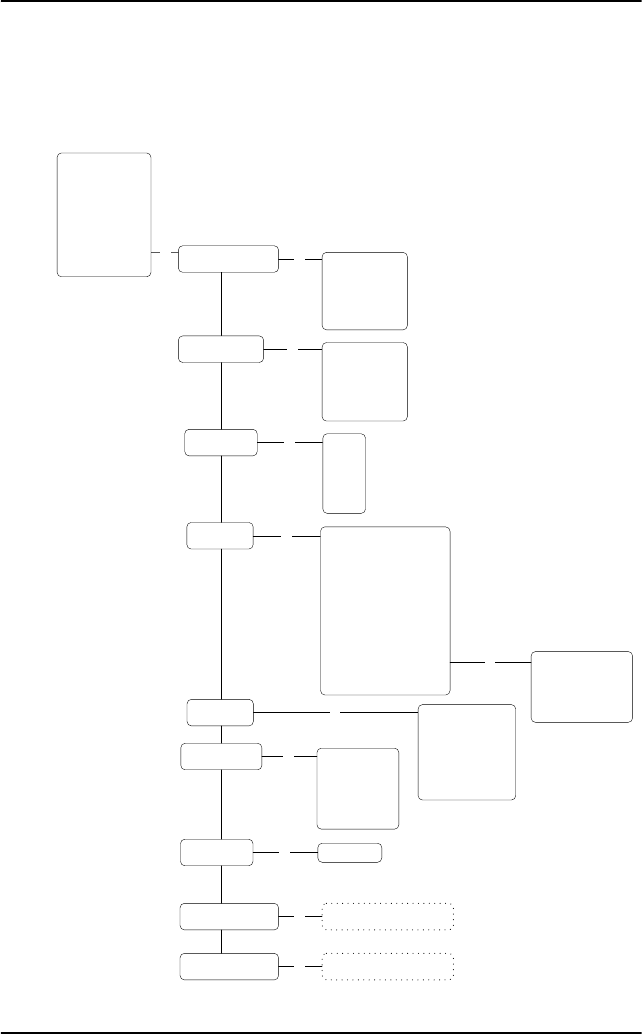
Chapter 5: System operation
144 Full Feature handset operation (SDU)
The Status menu
To access the Status menu, enter the main menu, scroll down to
Status and press C.
&KDQQHOV
2.
1DY'DWD
,'V
6:9HUVLRQ
/$1
$FWLYH(UURUV
2.
/DWLWXGH
/RQJLWXGH
$OWLWXGH
6SHHG
1DY6RXUFH
,56$FWLYH
$+56$FWLYH
*36$FWLYH
6KRZ'HWDLOHG1DY
6KRZ$QWHQQD3RV
357
&
&
+6'
6%
2.
+HDGLQJ
3LWFK
5ROO
'RSSOHU9HO
2.
2.
0DLQ
+DQGVHW
+DQGVHW
+DQGVHW
+DQGVHW
2.
6FUROOWKURXJKDOLVW
RIDFWLYHHUURUV
2.
3KRQH%RRN
+DQGVHW6HWXS
5LQJ3URILOH
/RFN6\VWHP
/RJRQ0HQX
6\VWHP6HWXS
6WDWXV
0DLQWHQDQFH /RJRQ6WDWXV
2.
+
+6'
6%
,ULGLXP
,ULGLXP
6'8/$1
2.
6HUYLFHV
2.
+
+6'
6%
,ULGLXP
,ULGLXP
(UURU/RJ
6FUROOWKURXJKDOLVW
RIORJJHGHUURUV
2.
6'86HU1R
+3$6HU1R
&06HU1R
+6'6HU1R
+6',61
,&$2
2QO\VKRZQLI,ULGLXPLVLQVWDOOHG

Chapter 5: System operation
Full Feature handset operation (SDU) 145
5555
System operation
To view the logon status
Select Logon Status to display the logon status of:
•the H
+ channel (Classic Aero)
•the HSD channel (Swift64)
• the SBU channel (SwiftBroadband)
• Iridium 1 (if installed)
• Iridium 2 (if installed)
Use B and E to select among the channels.
To view the status of services
Select Services to display the availability of:
•the H
+ service (Classic Aero)
•the HSD service (Swift64)
• the SBU service (SwiftBroadband)
• Iridium 1 (if installed)
• Iridium 2 (if installed)
Use B and E to select among the services.
To view the signal strength of the channels
Select Channels to display the signal strength (C/No in dBHz) of:
•PRT (P-channel)
•C1 (H
+ voice channel) (Classic Aero)
•C2 (H
+ voice channel) (Classic Aero)
•HSD (Swift64 channel)
• SBU (SwiftBroadband channel)
Use B and E to select among the channels.
Note
For the channels to work properly, the value of the signal strength
should be above the values mentioned below:

Chapter 5: System operation
146 Full Feature handset operation (SDU)
• P-Channel: above 35 dBHz
• C-Channels: above 42 dBHz
• HSD-Channel (Swift64): above 40 dBHz (TDM ~ Global)
• HSD-Channel (Swift64): above 54 dBHz (ISDN/MPDS ~ Spot)
• SBU-Channel (SwiftBroadband): above 41 dBHz (Global)
• SBU-Channel (SwiftBroadband): above 48 dBHz (Regional)
• SBU-Channel (SwiftBroadband): above 58 dBHz (Narrow)
If no signal is present, the display shows N/A.
To view the navigation data
Select Nav data to display the navigation data:
•Latitude (in degrees, minutes, seconds)
•Longitude (in degrees, minutes, seconds
•Altitude (in feet)
•Speed (ground speed in knots)
•Nav source – the source used for navigation; can be IRS or
AHRS+GPS
•IRS Active – shows whether or not the IRS is active
•AHRS Active – shows whether or not the AHRS is active
•GPS Active – shows whether or not the GPS is active
• Show Detailed Nav
•Heading – (0 to 360 degrees)
•Pitch (in degrees U or D (up or down))
•Roll (in degrees L or R (left or right))
•Doppler Velocity - the speed of the aircraft relative to the
satellite, given in knots.
•Show Antenna Pos – the position of the antenna in degrees
relative to the attitude of the aircraft, given as the Azimuth (horizontal
position) and the Elevation (vertical position).
Use B and E to select among the Navigation parameters.

Chapter 5: System operation
Full Feature handset operation (SDU) 147
5555
System operation
To enter the Show Detailed Nav menu, scroll to Show Detailed
Nav and press C.
To view serial numbers and ICAO address
Select ID to display:
• SDU Ser. No. (Serial number of the Satellite Data Unit)
• HPA Ser. No. (Serial number of the High Power Amplifier)
•CM Ser. No. (Serial number of the Configuration Module)
• HSD Ser. No. (Serial number of the HSD board)
• HSD ISN (Inmarsat Serial number of the HSD channel (Swift64))
• ICAO (ICAO Address)
Use B and E to scroll through the numbers.
The serial number of the SBU can be found in the SBU web interface, see
Use the Dashboard on page 170.
To view the software version
Select SW version to display the version number and certification
level of:
•Main software
• Handset 1 firmware
• Handset 2 firmware
• Handset 3 firmware
• Handset 4 firmware
Use B and E to scroll through the types of software.
To view the LAN status
Select LAN to view the status of the network. You may view:
•SDU LAN (the status of the LAN connected to the SDU)
The status can be “connected” or “disconnected”.

Chapter 5: System operation
148 Full Feature handset operation (SDU)
To view active errors
Select Active errors to display information of any active errors.
If there is more than one error, use B and E to scroll through the error
list.
To view the error log
Select Error Log to display a list of sessions. For each session is
indicated if there were errors (the display reads e.g. 2 items below the
session number) or if there were no errors (the display reads Empty).
Use B and E to scroll through the list of sessions.
To see details for a session, press C. Use B and E to scroll through
the details.
For each session, the display shows the start time, the Build ID and the end
time of the session. If there are errors, the display also lists the error text
and the error code for each error.
Maintenance (reset)
You can initiate a reset of the system.
Select Maintenance and press C again.
Use E to select Yes, then press C to reset the system.
OK
Maintenance
Reset OK
Phone Book
HandsetSetup
Ring Profile
Lock System
Logon Menu
System Setup
Status
Maintenance The system reboots.OK
Reset now
Yes

Chapter 5: System operation
MCDU operation 149
5555
System operation
MCDU operation
This section describes how to access the menu system using the keys and
display of the MCDU.
•Operate the MCDU
•AVIATOR 700 main menu
•SUBMENU
•LOCK menu
•SYSTEM menu
•LOGON menu
•STATUS menu
Operate the MCDU
The MCDU is used to control and operate the SATCOM equipment from
the cockpit. A subset of the MCDU menus and functions are identical to
those of the Full Feature handsets. The following sections describe the
AVIATOR 700 menu functions of the MCDU and explain how to navigate
the MCDU.
See also To enter the SATCOM subsystem on page 86.
Note
This chapter only describes the part of the MCDU functions that
concerns the AVIATOR 700 system. For information on other
functions in the MCDU, refer to the documentation delivered with
your MCDU and, if relevant, with any other connected equipment.

Chapter 5: System operation
150 MCDU operation
AVIATOR 700 main menu
AVIATOR 700 (logged on)
The AVIATOR 700 main menu is shown
when initially accessing the AVIATOR 700
subsystem. The content of the SATCOM
MAIN menu depends on the logon status and
the presence of errors. Upon successful
logon, the MCDU display shows:
•MANUAL DIAL presents an extended
set of features for dialing. For more
information about MANUAL DIAL, see
Make or receive a phone call (MCDU) on page 87.
•DIRECTORY gives access to the user-defined directory of phone
numbers.
•SUBMENU gives access to system configuration, status and other
information. For detailed information on this menu see the following
section.
•PRIORITY configures the Classic Aero (H+) call priority of outgoing
calls. This is visible only if logged on. For further information on call
priorities see To make a call (air to ground) (MCDU) on page 88. The
possible values are: PUBLIC, NON-SAFETY, SAFETY and EMERGENCY
•REDIAL lists the 10 most recent calls made. Press the or key next
to a number to activate a call.
•EMCON (Emission Control): This option will preempt all active calls, log
off satcom and establish radio silence. This is visible only if configured
in the Aero-SDU Configuration Program.
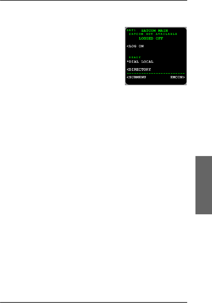
Chapter 5: System operation
MCDU operation 151
5555
System operation
AVIATOR 700 main menu (logged off)
If the system is not logged on, the SATCOM
MAIN menu looks as shown in the image to
the right.
•LOG ON allows you to log on the system
and to change the logon settings.
•DIAL LOCAL activates a call to a local
phone. Use the numerical keys on the
keypad to dial the number of the local
phone directly from the main menu.
•DIRECTORY gives access to the user-defined directory of phone
numbers.
•SUBMENU gives access to system configuration, status and other
information. For detailed information on this menu see the following
section.
•EMCON (Emission Control): This option will preempt all active calls, log
off satcom and establish radio silence. This is visible only if configured
in the Aero-SDU Configuration Program.
SUBMENU
The SUBMENU view contains the following menu items:
•LOCK allows you to lock the keypads of all handsets connected to the
SDU.
•LOGON allows you to log on or off the system, and to change the logon
settings.
•SYSTEM allows you to view or change system parameters such as ring
profiles, PIN codes, handsets and known GESs, LESs and satellites.
•STATUS contains system status such as logon status, navigational data,
software and hardware versions, active errors and error log.
The SUBMENU view contains the following selection item:
•RINGPROFILE allows you to select the currently active ring profile
from a list that can be configured. The ring profile is applied

Chapter 5: System operation
152 MCDU operation
immediately to all handsets connected to the SDU. For more
information on the predefined profile TAKEOFLANDING see RING
PROFILES on page 156.
For an overview over the menus of the MCDU se Menu tree for the MCDU
on page 213.
LOCK menu
The SDU can be locked so that new calls can not be initiated with handsets
connected to the SDU. Locking the system will also block the user interface
on all Full Feature Handsets and MCDUs. Note that a Normal User PIN code
must be defined before you can use this feature.
To lock all handsets connected to the SDU and all MCDUs, do as follows:
1. Enter the LOCK view.
2. Type in the Normal User PIN code.
3. Select button next to PIN code.
4. All SDU user interfaces are now locked.
5. To unlock the SDU type in the Normal User PIN code and select the
button next to the PIN code. All user interfaces will be unlocked.
If you have forgotten the PIN code, contact your aircraft installation and
service center or your local distributor.
Important
The lock function applies only to the SDU and handsets
connected to the SDU. It does not prevent users from
initiating calls and start new data sessions from devices
connected to the SBU while the SDU is locked.
Note
If power cycling the system while it is locked, it will stay locked
after power up.
Note
You can unlock a single Full Feature Handset by typing in the
Normal user PIN code in that handset and pressing C.

Chapter 5: System operation
MCDU operation 153
5555
System operation
LOGON menu
The logon policy of the system can be
configured for either automatic or manual
logon. In automatic mode, the AVIATOR
700 system automatically logs on to a
satellite. For manual logon, the crew can
explicitly select the satellite and GES for
log on and hand over, and initiate hand
overs at any time. Typically, the logon
policy is set to automatic mode.
The LOGON view contains the following
menu items:
•MANUAL LOGON allows to select a specific GES for logon from a
predefined list of all known GESs. This is visible only in manual mode.
•CUSTOM LOGON allows to select any satellite and GES identifiers for
logon. This is visible only in manual mode.
•SETTINGS allows to change the logon policy and modify the list of
preferred GESs and LESs.
The LOGON view contains the following functions:
•AUTO LOGON: Select this function to initiate the logon procedure
toward the most appropriate satellite and GESs while taking the list of
preferred GESs into account.
•LOGOFF logs off the system. Both in manual and automatic mode, the
user must take action to logon the system again.
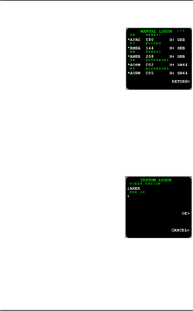
Chapter 5: System operation
154 MCDU operation
MANUAL LOGON
This view presents a list of all known GESs.
For each GES the following information is
shown:
• Name of the GES.
• Satellite on which the GES operates.
• Identifier of the GES.
• Services supported by the GES.
To logon to a specific GES, press the arrow
key next to the row of the GES. The list may span several pages. To browse
to the next page, press the button NEXT.
The right hand side of the view shows the services of the GES.
Example: If you select the GES AMER 208 you will get the services H+
(Classic Aero) and SBB (SwiftBroadband). If you select the GES
AORW 002 you will get the services H+ (Classic Aero) and
SW64 (Swift64).
CUSTOM LOGON
To initiate logon on a specific satellite and
GES do as follows:
1. Enter the CUSTOM LOGON view.
2. Select a satellite.
3. Type in the identifier of the intended
GES on the scratch pad. You find the GES
ID in List of available GESs on page 215.
4. Press the arrow key next to the GES identifier and select OK.

Chapter 5: System operation
MCDU operation 155
5555
System operation
SETTINGS
The SETTINGS view contains the following items:
•LOGON POLICY indicates the current logon policy. The available
options are:
• AUTOMATIC
• MANUAL
Changing this setting takes effect immediately, but does not trigger a
log on or log off. Hence, if the system is not logged on and the logon
policy is changed from manual to automatic, the user must enter the
LOGON view and select AUTO LOGON to logon the system.
•Pref. H+ GES allows configuration of the user preferred GESs. This
view lists the user prioritized GESs. The order and prioritization defines
which GES the system will attempt logon with logon policy automatic.
This list is typically configured during installation.
•PREF. ISDN LES allows configuration of the user preferred LESs for
ISDN use. This view lists the user prioritized LESs for ISDN usage. The
order and prioritization defines which LES the system will use for ISDN
when the system is logged onto an I3 satellite. This list is typically
configured during installation.
•PREF. MPDS LES allows configuration of the user preferred LESs for
MPDS use. This view lists the user prioritized LESs for MPDS usage. The
order and prioritization defines which LES the system will use for MPDS
when the system is logged onto an I3 satellite. This list is typically
configured during installation.
The preferred GESs and LESs are typically configured during installation.
Note
Entries in this list must be in the list of Known GES. For further
information see CONFIGURE on page 158.
Note
Entries in this list must be in the list of Known LES. For further
information see CONFIGURE on page 158.
Note
Entries in this list must be in the list of Known LES. For further
information see CONFIGURE on page 158.

Chapter 5: System operation
156 MCDU operation
SYSTEM menu
The SYSTEM view contains the following menu items:
• RINGPROFILES
• MODIFY PIN
• CONFIGURE
• TECHNICAL
• RESET
RING PROFILES
In this view you can configure up to 5 different ring profiles PROFILE1 to
PROFILE4 and PROFILE5 <TAKEOFLANDING. Select a profile to
view or edit it. A ring profile applies to the SDU of the AVIATOR 700 system
and determines the ring setting (on/off) of each handset, ISDN and
annunciator interfaces connected to the SDU. The profile name
TAKEOFLANDING is predefined. If the function Chime/Lamps Inhibit is
used in the installation, this profile is automatically activated during takeoff
and landing.
The PROFILE view contains ring setting for each of the following devices
connected to the SDU:
• HANDSET #1
• HANDSET #2
• HANDSET #3
• HANDSET #4
• POTS #5
• POTS #6
• ISDN
• ANNUNCIATOR 1
• ANNUNCIATOR 2
• ANNUNCIATOR 3
Each device can be set to RINGER OFF or RINGER ON.

Chapter 5: System operation
MCDU operation 157
5555
System operation
To assign a name to a ring profile, do as follows:
1. Type in the name on the scratch pad.
2. Press the arrow key next to NAME.
To delete a ring profile, do as follows:
1. Enter the RINGPROFILES view.
2. Select a profile with the arrow key next to the profile.
3. Press the CLR key on the MCDU.
4. Press the arrow key next to NAME.
5. Select OK.
MODIFY PIN
The MODIFY PIN view lists the three PIN types and their current status
(enabled or disabled):
•Normal User PIN. This PIN code is used for the LOCK function, see also
LOCK menu on page 152.
•Super User PIN
•Service Provider PIN
For more information on PIN codes see Restricted access on page 114.
To enable a PIN code, do as follows:
1. Enter the MODIFY PIN view.
2. Press the arrow button next to the PIN code to be changed.
3. Enter the PIN code.
4. Select NEW PIN.
5. Enter the PIN code a second time.
6. Select RETYPE PIN.
7. Select OK.

Chapter 5: System operation
158 MCDU operation
To modify a PIN code, do as follows:
1. Enter the MODIFY PIN view.
2. Press the arrow button next to the PIN code to be changed.
3. Enter the old PIN code.
4. Press the arrow button next to the PIN code.
5. Enter the new PIN code.
6. Select NEW PIN.
7. Enter the new PIN code a second time.
8. Select RETYPE PIN.
9. Select OK.
To disable a PIN code, do as follows:
1. Enter the MODIFY PIN view.
2. Press the arrow button next to the PIN code to be changed.
3. Enter the old PIN code.
4. Select DISABLE PIN.
5. Select OK.
CONFIGURE
The CONFIGURE view contains the following items:
•HANDSET TYPE allows you to see the types of handsets connected to
the SDU. In this view you can see the configuration of the handsets
connected to the SDU. This setting is typically configured during the
installation of the system. For further information see the AVIATOR 700
Installation and Maintenance Manual.

Chapter 5: System operation
MCDU operation 159
5555
System operation
•AUDIO 1 can be used to configure the audio of the cockpit headset, if
connected to the AVIATOR 700 system.
•MIC configures the volume of the microphone
•SPEAKER configures the volume of the speaker
•SIDETONE adjusts the sidetone percentage
•SILENCE enables (OFF) or suppresses (ON) ring tone
•COMF. NOISE configures the comfort noise
•AUDIO 2 can be used to configure the audio of the cockpit headset, if
connected to the AVIATOR 700 system. See AUDIO 1.
•SATELLITE allows configuration of the list of satellites and known
GESs and LESs.
KNOWN GES — This list is used from other parts of the user interface,
e.g. when making a manual logon (see MANUAL LOGON on page 154).
The list of preferred GES' is a subset of the list of known GES'.
KNOWN LES — This list contains the LESs for which the lists of
preferred LES' can be constructed.
INIT SAT — The first time the AVIATOR 700 system logs onto a
satellite it locates the satellite based on the information associated with
the satellites listed in this view.
•DISCLOSE POS indicates whether the position of the system is
disclosed to the GESs and LESs. This setting is typically configured
during the installation of the system. For further information see the
AVIATOR 700 Installation and Maintenance Manual.
•FAX configures the connection of fax to the POTS interfaces #5 and
#6. This setting can be used to prevent ringing on the POTS interfaces
during a broadcast call in case a fax has been connected. This setting is
Note
These settings only affect the cockpit headsets when they are
used by the AVIATOR 700 system.
Note
This list is typically created during installation.
Note
This list is typically created during installation.
Note
This table is created at the factory and typically should not be
modified.

Chapter 5: System operation
160 MCDU operation
typically configured during the installation of the system. For further
information see the AVIATOR 700 Installation and Maintenance
Manual.
TECHNICAL
TECHNICAL is for internal use only.
RESET
To reset (i.e. power cycle) the AVIATOR 700 system including the SBU, do
as follows:
1. Enter RESET view.
2. Select ACCEPT.
This operation will restart the satcom. The operation will take several
minutes.
STATUS menu
In the menus listed in the STATUS view you can find a large set of
AVIATOR 700 status information:
•LOGON shows which services are logged on.
•SERVICES shows which services are ready for use.
•CHANNELS shows which channels are in use and their respective signal
strength.
•NAV DATA shows detailed input from the external navigational source.
•IDS displays the serial numbers and ICAO address of the SDU.
•SW VERSION shows the software version and certification level of the
SDU and connected Full Feature handsets.
•LAN shows the status of the SDU LAN connection.
•ACTIVE ERRORS lists the active essential errors.
•ERROR LOG contains logs from previous power cycles.

Chapter 5: System operation
MCDU operation 161
5555
System operation
LOGON
This status is shown for the following services:
•H+ (Classic Aero)
•HSD (Swift64)
•SBU (SwiftBroadband)
•Iridium 1 (if installed)
•Iridium 2 (if installed)
The logon status can take one of the values LOGGED ON or LOGGED OFF.
SERVICES
This view shows the availability of the following services:
•H+ (Classic Aero)
•HSD (Swift64)
•SBU (SwiftBroadband)
•Iridium 1 (if installed)
•Iridium 2 (if installed)
The service status can be AVAILABLE or UNAVAILABLE.
Note
The Classic Aero services are available on both I3 and I4 satellites,
while data services using SwiftBroadband are available exclusively
on I4 satellites. The AVIATOR 700 system uses Swift Broadband
for data services whenever possible. Swift64 is used as a fallback
solution for areas where SwiftBroadband is not available.

Chapter 5: System operation
162 MCDU operation
CHANNELS
This view lists the signal to noise ratio (C/No
in dB Hz) for each channel in the system. For
further information see To view the signal
strength of the channels on page 145.
NAV DATA
This view shows information about the navigational input received from
external systems:
•LATITUDE — in degrees, minutes, seconds.
•LONGITUDE — in degrees, minutes, seconds.
•ALTITUDE — in feet.
•SPEED — ground speed in knots.
•NAV SOURCE — the external source used for navigation which can be:
•IRS or
•AHRS+GPS
IRS shows the status of the IRS input. AHRS shows the status of the
AHRS input. GPS shows the status of the GPS input.
The NAV DATA view contains the following menus:
• DETAILED NAV
This view shows the following detailed information:
•HEADING — 0 to 360 degrees.
•PITCH — in degrees (U = up; D = down).
•ROLL — in degrees (L = left; R = right).
•DOPPLER VELOCITY, — the speed of the aircraft relative to the
satellite (knots).
• ANTENNA POS

Chapter 5: System operation
MCDU operation 163
5555
System operation
This view shows the antenna pointing data. The pointing is relative to
the attitude of the aircraft:
•AZIMUTH — horizontal position (degrees)
•ELEVATION — vertical position (degrees)
IDS
This view displays the serial numbers and IDs of the system units, including
the ICAO address of the SDU.
You find identifiers related to the SBU (e.g. IMSI number and SBU serial
number) on the dashboard of the SBU web interface. For further details see
Introduction to the SBU web interface, Properties on page 171.
SW VERSION
This view displays the software version and certification level of the SDU
(MAIN) and the firmware version of each connected Full Feature handset.
LAN
This view shows the status of the HSD (Swift64) LAN connection (SDU). It
can be CONNECTED or NOT CONNECTED.
ACTIVE ERRORS
This view lists the active essential errors. For more information about a
specific error see the AVIATOR 700 Installation and Maintenance Manual.
ERROR LOG
This view contains a list of logs. The first log is the current log. A new log is
created upon each power cycle. Each log contains:
• Start time of the session (power cycle).
• End time of the session.
• Build ID (extended software version).
• Text and identifier for each error message (if any).
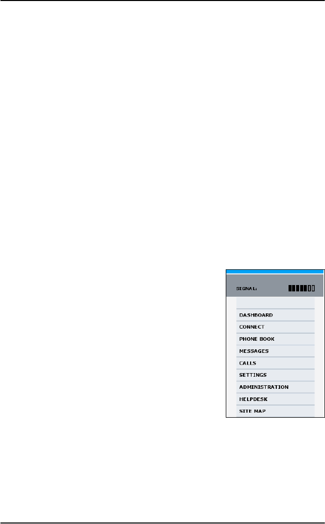
Chapter 5: System operation
164 Use the SBU web interface
Use the SBU web interface
In the following sections you can read about:
•Introduction to the SBU web interface
•Use the SBU phone book
•Use the Call log
•Start or stop any data session
•Call log handling
•Set data limits
•Set up the local exchange function
•Remote management and activation
•Remote activation of the SBU with SMS
•Restricted dialing
Introduction to the SBU web interface
The web interface is built into the system and
used for operating, setting up and configuring
the system.
You can access the web interface from a
computer with a standard Internet browser. The
parts of the web interface that are used in daily
use of the system are described in detail in the
following paragraphs. The parts of the web
interface that are used during system installation
are described in detail in the AVIATOR 700
Installation and Maintenance Manual.
Connect to the web interface
To access the web interface, an Internet browser must be installed on the
computer. Connect your computer to the AVIATOR 700 system, using one
of the LAN interfaces (up to 6) installed in the aircraft cabin or use the
Wireless connection, if available.
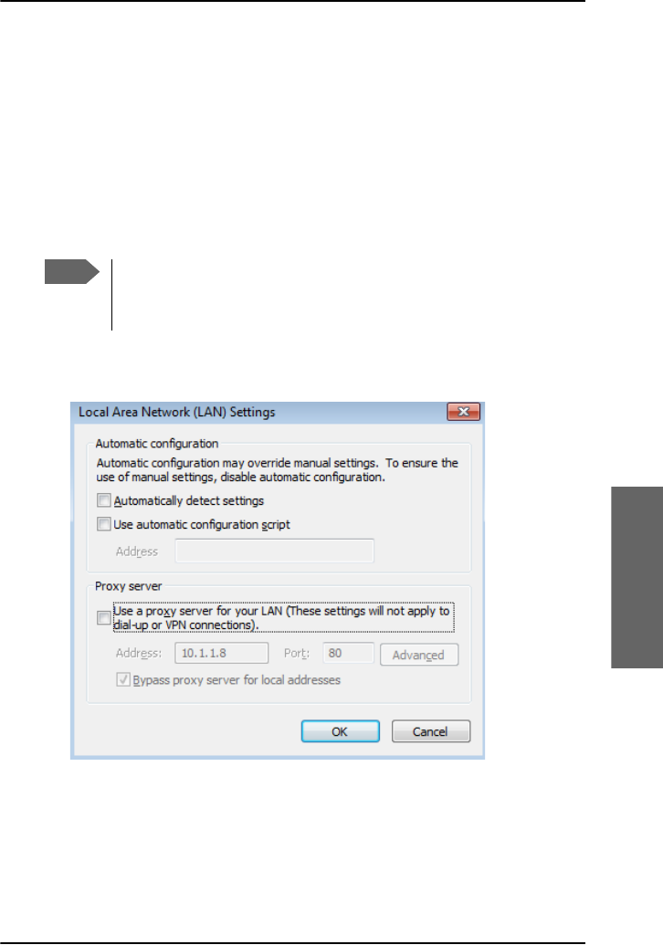
Chapter 5: System operation
Use the SBU web interface 165
5555
System operation
Proxy server settings
If you are connecting your computer using a LAN or WLAN interface, the
Proxy server settings in your browser must be disabled before accessing
the web interface. Most browsers support disabling of the Proxy server
settings for one specific IP address, so you can disable Proxy server settings
for the web interface only, if you wish. Consult your browser help for
information.
To disable the use of a Proxy server completely, do as follows:
1. In Microsoft Internet Explorer, select Tools > Internet Options >
Connections > LAN Settings.
2. Clear the box labeled Use a proxy server for your LAN.
3. Click OK.
When the proxy server settings are disabled, close and restart your browser.
You may need to change this setting back on return to your Internet
connection.
Note
The following description is for Microsoft Internet Explorer.
If you are using a different browser, the procedure may be
different.
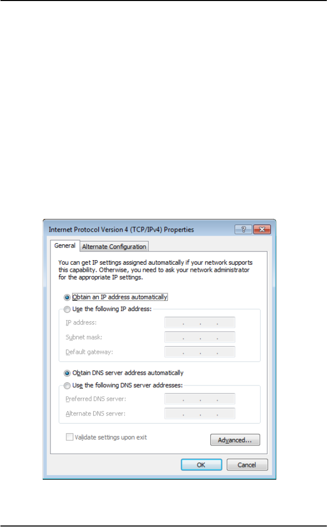
Chapter 5: System operation
166 Use the SBU web interface
IP address and DNS server address setup
To check whether automatic IP address and DNS server address is obtained
automatically for your computer, do as follows (example for Windows 7):
1. Go to Control Panel > Network and Internet > Network and
Sharing Center.
2. Click on the LAN connection you want to use.
3. Select Properties, highlight Internet Protocol Version 4
(TCP/IPv4).
4. Click Properties.
5. Make sure that the following is selected:
- Obtain an IP address automatically
- Obtain DNS server address automatically
Allocating IP addresses and DNS server lookups are handled by the system.

Chapter 5: System operation
Use the SBU web interface 167
5555
System operation
Access the web interface
To access the web interface, do as follows:
1. Connect your computer to the system.
2. Make sure that the AVIATOR 700 system is fully operational in the
aircraft.
3. Open your Internet browser and enter the IP address of the system. The
default IP address is http://192.168.0.1. You can also type
http://ut.bgan if your system use automatic assignment of IP to
devices on the network (DHCP).
If your system uses a different IP address, you can look it up by
connecting an IP handset and entering the BGAN menu. Select
Status > Properties > Local IP address.
Note
If the IP address has been changed and you do not have the new
address, contact your system administrator and request the new
IP address.
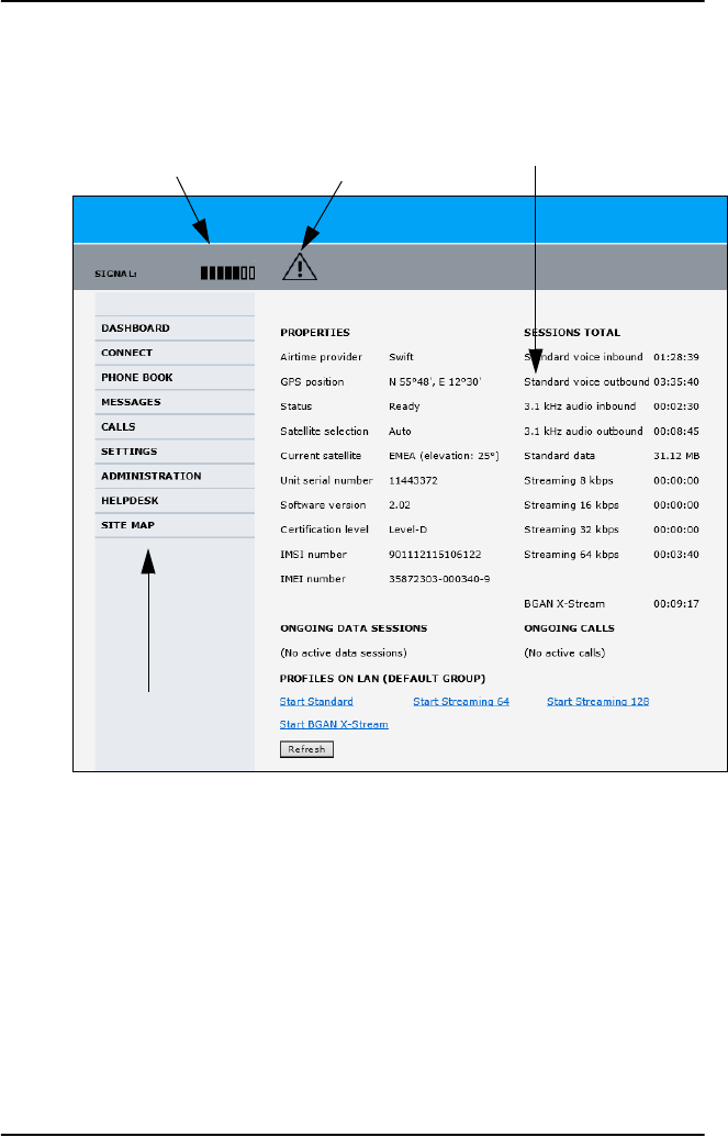
Chapter 5: System operation
168 Use the SBU web interface
Overview of the web interface
The web interface consists of the following sections:
•The navigation pane holds the main menu. Clicking an item in the
menu opens a submenu in the navigation pane or a new page in the
contents section.
•The status field shows the signal strength.
•The icon bar shows icons for new SMS messages and for active events,
when relevant. For explanations of the icons, see the next section, Icons
in the icon bar.
•The contents section shows the page selected in the navigation pane.
This section is used t view or change settings, or for performing actions.
Contents sectionStatus field Icon bar
Navigation pane
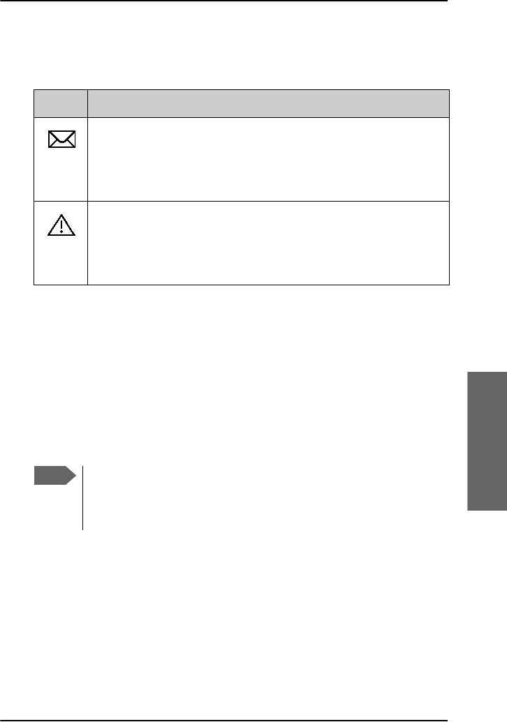
Chapter 5: System operation
Use the SBU web interface 169
5555
System operation
Icons in the icon bar
The following icons may appear in the icon bar in the web interface:
Navigate the web interface
•To expand a menu, click the menu in the navigation pane.
•To access status and settings, click the relevant subject in the
navigation pane or click the relevant icon in the icon bar. The status or
settings are displayed in the contents section.
•To get an overview over the submenus available use the site
map, click SITE MAP in the navigation pane. Click on items in the site
map to go directly to the relevant location.
Icon Explanation
A new SMS message, or information of Voice mail, has arrived.
Click the icon to see new messages or information of Voice
mail. For further information, see To receive a message on
page 97.
An event is active. Click the icon to see a list of active events.
For explanations of the event messages, see the AVIATOR 700
Installation and maintenance manual. Note that this icon will
remain in the icon bar as long as the event is still active.
Note
Some parts of the web interface may be greyed out if the user
permissions are limited. For information on how to set up user
permissions, see the AVIATOR 700 Installation and maintenance
manual.
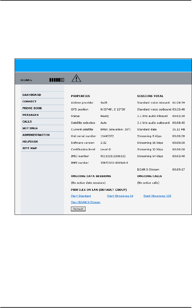
Chapter 5: System operation
170 Use the SBU web interface
Use the Dashboard
The Dashboard is the first screen that is displayed when you enter the IP
address of the web interface of the AVIATOR 700 system. The Dashboard is
used for control and inspection of ongoing communication and for viewing
properties and status of the system and antenna.
Chapter 5: System operation
Use the SBU web interface 171
5555
System operation
Properties
The PROPERTIES section of the DASHBOARD shows the following
information:
•Airtime provider. The name of your Airtime Provider.
•GPS position. The GPS position of your AVIATOR 700 system.
•Status. The status of the system and antenna.
•Satellite selection. The satellite selected for logon.
•Current satellite. The current satellite and elevation angle.
•Unit serial number. The serial number of the SwiftBroadband Unit of
the AVIATOR 700 system.
Note
In some cases, the BGAN network does not allow the position
to be displayed to the user. If this is the case, the display may
just show GPS acquired. This means that the GPS position is
received, but the user is not allowed to see it.
This also applies if the AVIATOR 700 is not yet registered on
the BGAN network, but the GPS position is received.
Status Description
Scanning The system is trying to logon to a satellite and waiting
for the GPS position.
Ready The system is ready for use.
Data
Active
The data connection is active, data are transferred.
Logged off 1. The SBU has logged off the I4 satellite and the
AVIATOR 700 has switched over to an I3 satellite.
Data services can be used over Swift64 through
the SDU.
2. The AVIATOR 700 system is logged off.

Chapter 5: System operation
172 Use the SBU web interface
•Software version. The version of the software embedded in the
SwiftBroadband Unit.
•Certification level. This field shows whether the system is Level-D or
Level-E certified.
•IMSI number. The IMSI number (International Mobile Subscriber
Identity) of the system. It is a unique number that is stored on the SIM
card inside the system and sent to the network.
•IMEI number. The IMEI number (International Mobile Equipment
Identity) of the system. This is a unique number that identifies your
system.
Viewing information on calls and data sessions
The following sections in the Dashboard show information on calls and
data sessions.
•ONGOING DATA SESSIONS is a list of data profiles that are currently
active, including the external IP address that is assigned to each profile.
•SESSIONS TOTAL lists the totals for each connection type. The list
shows the time connected for voice and Streaming data, and MB
transferred for Standard data.
•ONGOING CALLS is a list of calls that are currently active. The list
shows the call type and the time connected for each call.
The counters show totals for connections since the counters were last
cleared. For information on how to clear the counters, see Call log handling
on page 180.
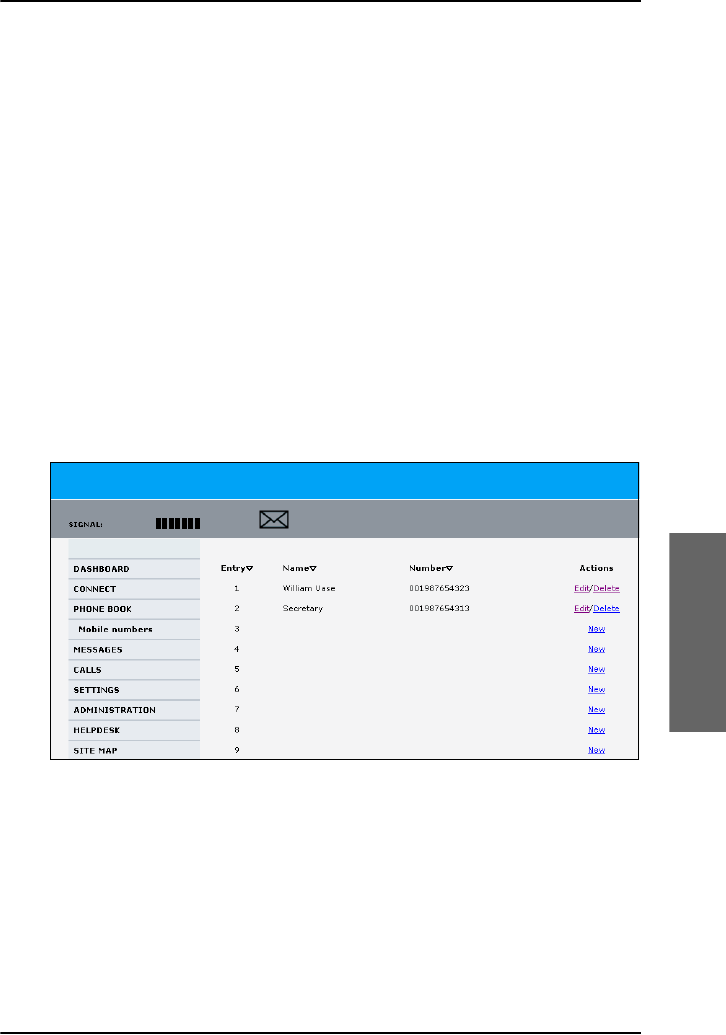
Chapter 5: System operation
Use the SBU web interface 173
5555
System operation
Use the SBU phone book
The phone book is stored in the Configuration module of the SBU in the
AVIATOR 700 system. In the phone book you can:
• Look up phone numbers.
• Look up short-dial numbers for easy dialing from a handset.
• Modify or delete existing names and phone numbers, or add new names
and phone numbers.
The numbers of the phones available on the aircraft and the mobile number
of the system might already be entered when the system was initially
configured.
To access the phone book
To access the phone book, select PHONE BOOK from the left navigation
pane.
The phone book shows all entries with entry number, name and phone
number. Empty placeholders are also included. The phone book holds 199
entries divided into subpages. To select the subpages you want, click the
relevant link at the bottom of the page.
To sort the phone book, click the title of the column you wish to sort by. For
example, to sort by the names in the phone book alphabetically, click on
Name in the top row of the phone book.

Chapter 5: System operation
174 Use the SBU web interface
Short dial
The entry number in the phone book is the Short dial number. When
making a call from the system you can use this number instead of dialing
the entire phone number. Dial:
00 <short dial> followed by # or off-hook key for short-dial numbers 1 -
99.
0 <short dial> followed by # or off-hook key for short-dial numbers 100 -
199.
Example: To call the third entry in the phone book from an analog phone,
take the phone off hook and dial 003 #.
To add a new entry
To add a new entry, do as follows:
1. In the phone book, locate the empty entry number where you want to
add the new phone number and click New.
2. Type in the name and phone number of the new entry and click Save
entry.
The new name and number are now listed at the specified entry number
in the phone book.
To modify an entry in the phone book
To modify an entry, do as follows:
1. In the phone book, click Edit next to the entry you want to modify.
2. Modify the name or number as wanted and click Save entry.
The name and/or number in the selected entry is now replaced with the
new information.
To delete an entry in the phone book
To delete an entry, click Delete next to the entry you want to delete.
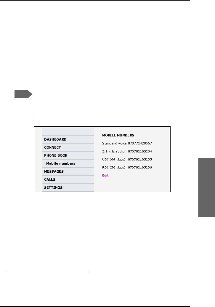
Chapter 5: System operation
Use the SBU web interface 175
5555
System operation
To delete all entries in the phone book
To delete all the entries in the phone book, click Delete all entries in
phone book at the bottom of the PHONE BOOK page.
To view the mobile numbers and additional numbers1
To view the mobile numbers of the AVIATOR 700 system, select PHONE
BOOK > Mobile numbers from the left navigation pane. The mobile
numbers are the phone numbers to use when making a call to the AVIATOR
700 system.
The example above is for a system without Multi-voice.
To enter or edit the mobile numbers
To enter or edit the mobile numbers, click Edit at the bottom of the page,
type in the numbers received from your service and airtime provider and
click OK.
If Multi-voice is part of your system, the additional numbers from
your airtime provider can be entered in the web interface
1. Available for systems with Multi-voice and subscriptions with
additional numbers.
Note
These numbers are not listed at delivery. They may have been
entered during initial configuration of the system or can be
entered at a later stage. The numbers are stated in the
documentation from the service and airtime provider.

Chapter 5: System operation
176 Use the SBU web interface
Use the Call log
The call log holds information on all calls and data sessions since it was last
cleared.
Information on total usage
To enter the CALLS page select CALLS from the left navigation pane. The
CALLS page contains information on usage for circuit switched
connections.
For more information on circuit switched services, see Circuit switched
(dialed) service on page 19.
The listed information includes:
• time connected using Standard Voice
• time connected using 3.1 kHz Audio.
Export the call log
You can export the call log file for archiving, surveillance or other tracking
purposes. The call log holds information on all calls and data sessions since
the call log was last cleared. For information on how to view the lists of calls
and data sessions, see the next section.
When there are more than 100 calls in the total list, the oldest calls are
automatically removed to make room for new calls.
To export the entire call log to a file, do as follows:
1. In the CALLS page, click the link Export call log to file.
2. Browse to the location where you want to save the log.
3. Click OK.
Note
If power to the system is interrupted, the information stored in
the Call log for the currently ongoing calls (connection time) and
data sessions (transferred data) may be slightly inaccurate.

Chapter 5: System operation
Use the SBU web interface 177
5555
System operation
View the lists of calls
To see information on outgoing, received or missed calls or data sessions,
select one of the following lists from the left navigation pane in the CALLS
page:
•Outgoing calls shows the start time, receiving end phone number,
duration, type (Standard or 3.1 kHz Audio) and estimated charge of
each outgoing call.
•Received calls shows the start time, calling phone number, duration
and type (Standard or 3.1 kHz Audio) of each incoming call.
•Missed calls shows the start time, calling phone number and type
(Standard or 3.1 kHz Audio) of each incoming call that was not received.
•Standard data sessions shows the start time, bytes in, bytes out and
estimated charge of each Standard IP session.
•Streaming data sessions shows the start time, duration, type
(Streaming 8, 16, 32, 64, 128 kbps or X-Stream) and estimated charge
of each Streaming IP session.
Date and time is the international UTC time, received from the satellite. In
casual use, UTC is the same as Greenwich Mean Time (GMT).
For information on the available types of service, see AVIATOR 700
Services on page 4.
You can sort each of the lists by clicking the title of the column you wish to
sort by. If a list covers more than one page, you can click the relevant link at
the bottom of the page, to go to another page.
Note
The estimated charge is based on your entries under
ADMINISTRATION > Call charges. Thrane & Thrane does not take
responsibility for the correctness of this estimated charge. This
calculation is only a rough estimate of the charge, based on the
tariff entered by the user. Also, the airtime provider may have
different methods of calculating the charge.

Chapter 5: System operation
178 Use the SBU web interface
View the Voice mail number
The Voice mail number is the number you call to hear your incoming voice
mail.
To see the Voice mail number, select
MESSAGES > Message settings from the left navigation pane. The
Voice mail number field shows the Voice mail number.
Note
The Voice mail number is only listed if it is available on the SIM
card. Otherwise, refer to the information included with your
airtime subscription.
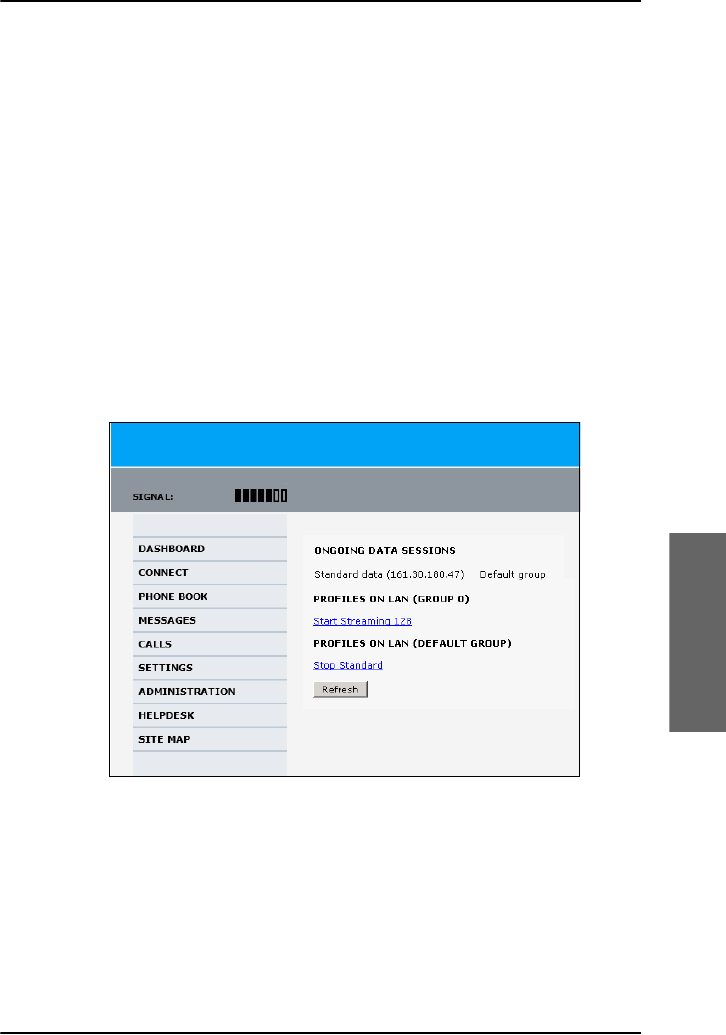
Chapter 5: System operation
Use the SBU web interface 179
5555
System operation
Start or stop any data session
If necessary, you can start and stop any data session for all network user
groups connected to the system. To use this feature you must login as an
administrator.
To start or stop any data session, do as follows:
1. Select CONNECT.
If you are not yet logged in as an administrator, enter the administrator
user name and password. The default user name is admin and the
default password is 1234. If the password has been changed, contact
your system administrator.
Under ONGOING DATA SESSIONS at the top you can see which data
sessions are currently active and which are allowed.
Example:
In the example above you could manually start the streaming 128
connection of the GROUP 0 and stop the standard connection of the
DEFAULT GROUP.
2. Click on the session you want to start or stop.
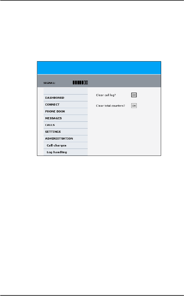
Chapter 5: System operation
180 Use the SBU web interface
Call log handling
To clear the logs of the system and/or reset the counters for the time
connected, do as follows:
1. From the left navigation pane in the ADMINISTRATION page, select
Log Handling.
2. To clear the Call log, click OK next to Clear call log?.
3. To clear the total counters, click OK next to Clear total counters?.
This resets the Time connected counters on the Calls page.

Chapter 5: System operation
Use the SBU web interface 181
5555
System operation
Set data limits
You can set a limit for the use of data services with the AVIATOR 700
system. You either specify a maximum number of MB for the standard data
connection, and/or a time interval from start to end for a streaming
connection.
If you have entered the call charges in the menu Call charges, the system
automatically calculates and displays the maximum charges for your data
sessions.
Once the entered limit is reached, the connection is automatically stopped.
This is recorded in the menu CALL containing a call log in which you can
see information on standard and streaming data sessions. To continue
using the data services you must start a new connection by clicking on the
desired connection on the Dashboard.
To set data limits, do as follows:
4. From the left navigation pane in the ADMINISTRATION page, select
Data limits.
5. Select the services to close automatically after a fixed amount of data
or period of time.
For Standard data type in the number of mega bytes (MB) allowed.
For streaming classes select a period of time from the drop down list.
6. Click Apply to save the settings.
Note
Thrane & Thrane A/S does not take responsibility for the
correctness of the estimated charges. This calculation is only a
rough estimate of the charge, based on the tariff entered by the
user. Also, the airtime provider may have different methods of
calculating the charge.
Note
If you set a data limit for the Standard data connection,
automatic activation of the Standard data connections is disabled
for all network user groups.
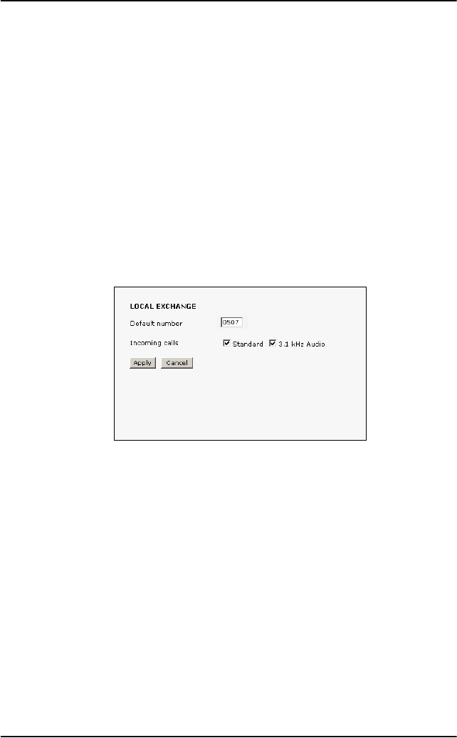
Chapter 5: System operation
182 Use the SBU web interface
Set up the local exchange function
If you want to call a specific phone connected to the terminal, use the local
exchange function. With this function enabled, when you dial the mobile
number of the terminal, a recorded message instructs you to dial the
number for the local phone you want to call. Your call is then transferred to
the requested phone and only the requested phone rings.
If the local exchange is not used (Incoming calls not selected), incoming
calls will per default cause all connected phones to ring.
To set up the local exchange, do as follows:
1. Select SETTINGS > Common > Local exchange from the left
navigation pane.
2. Type in the local number to which incoming calls are transferred to if
the caller dials * after calling the mobile number, or the caller dials
nothing after the recorded message.
3. Select the call types you want to direct to the local exchange.
If you use 3.1 kHz Audio for a fax machine only, do not select 3.1 kHz
Audio as this line is used for the fax.
If no call type is selected, the local exchange function is disabled
(default setting).
4. Click Apply.

Chapter 5: System operation
Use the SBU web interface 183
5555
System operation
Remote management and activation
Prepare the AVIATOR 700 for remote management
1. Verify that the AVIATOR 700 is correctly set up for this feature. How to
set up this feature is described in the Installation and Maintenance
Manual.
2. Activate a data connection in one of the following ways:
• Remote activation with SMS.
• Automatic activation of a data connection (not remote).
• Manual activation of a data connection (not remote).
3. Note the system’s external IP address, found in one of the following
ways:
• Unmanned SMS activation: You will receive an SMS with the IP
address when the system is powered up and operational.
• Connect a computer locally to the system and start the web
interface. The IP address of the system is shown in the Dashboard
under ONGOING DATA SESSIONS (in parenthesis).
This is the IP address you must use to access the system remotely.
If Static IP address is included in your airtime subscription, we
recommend using this IP address for the system in order to provide
easy access to the system.
Note
Note that only the SBU of the AVIATOR 700 can be accessed
remotely.
Some setup tasks must be done on the SBU before being able to
use the remote function. These tasks are described in the
following sections.

Chapter 5: System operation
184 Use the SBU web interface
Access the AVIATOR 700 from a remote location
To access the SBU from a remote location, do as follows:
1. On the remote computer, open a web browser.
2. Enter the IP address of the SBU followed by colon and the port number
http://<ip address>:<incoming port>.
• <ip address> is the address from step 3 above.
• <incoming port> is the port that has been defined during system
installation.
Example: If the IP address of the SBU is 161.30.180.12 and the
incoming port number defined in the Remote management
page in the web interface is 8080, enter
http://161.30.180.12:8080.
You are now connected to the SBU from the remote computer.
Note
Contact your installation center for further information on the
SBU IP address and port number. Your system may have a
static IP address that is assigned each time when the SBU logs
on.
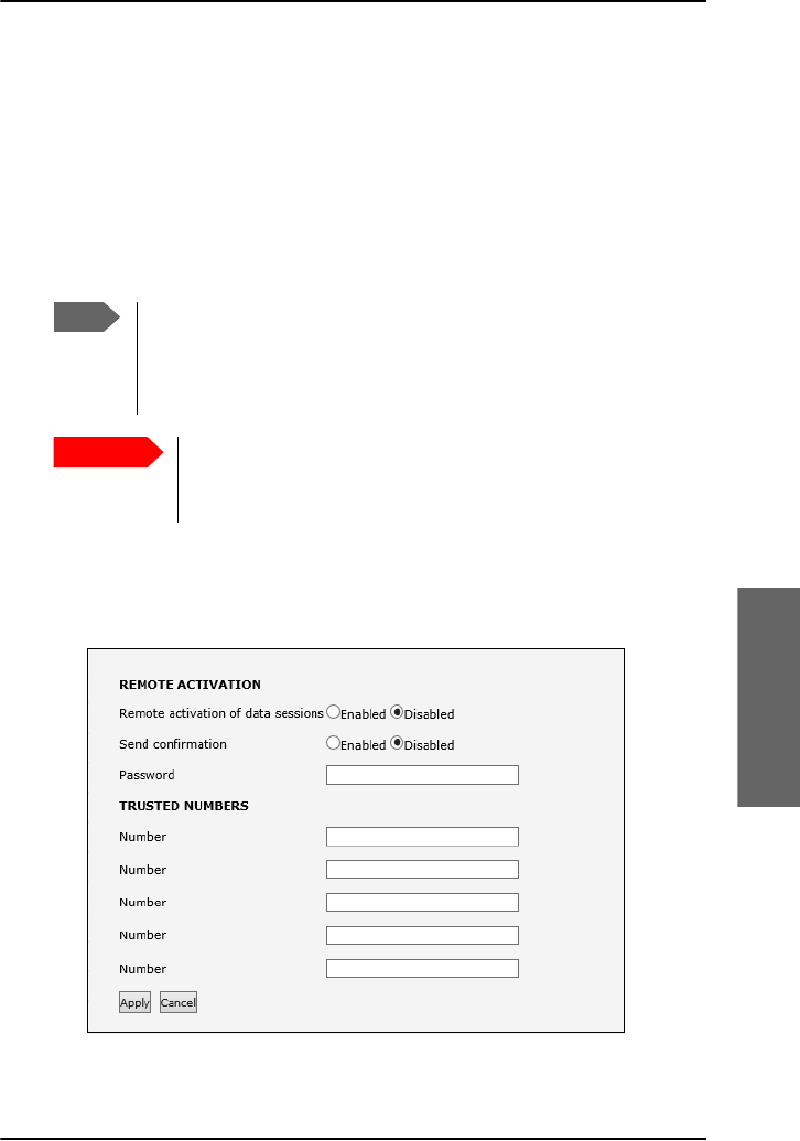
Chapter 5: System operation
Use the SBU web interface 185
5555
System operation
Remote activation of the SBU with SMS
If you want to remotely control the system, it must have activated a
connection. You can do this by sending an SMS to the system. The system
must be powered up and logged on to the satellite services to receive the
SMS and then start the connection. The SMS activation is always protected
by a password. You can set up the system to send an SMS confirmation on
the status of the connection, whether it is activated successfully or the
activation failed.
To set up the system for remote activation with SMS, do as follows:
1. From the left navigation pane, select ADMINISTRATION > Remote
activation.
2. Select whether remote activation should be Enabled or Disabled.
Note
The system must be logged on to the satellite services to
receive and accept an activation SMS. If the SMS is
considered too old or sent before the system has been
switched on and has logged on, the SMS will be ignored.
Important
This service is available if the service provider has an
interoperability agreement with Inmarsat that allows for
roaming. If in doubt, contact your service provider.
Chapter 5: System operation
186 Use the SBU web interface
3. Select whether confirmation by SMS should be Enabled or Disabled.
4. Enter the password. It can be up to 32 characters long. The characters
0-9, a-z and A-Z are allowed. The password is mandatory and must
match the password in the activation SMS.
5. Enter at least one trusted mobile number from which the system
accepts an activation SMS. If no numbers are entered the feature is
disabled automatically. Use the wild card * to accept a range of trusted
numbers.
6. Click Apply to save the new settings.
SMS format
The activation SMS must have the following format for activating and
deactivating a connection in the SBU:
•ACTIVATE <name of network user group>:<name of profile>
<password>
•DEACTIVATE <name of network user group>:<name of profile>
<password>
The password is case sensitive, the words ACTIVATE and DEACTIVATE are
not.
Examples for SMS
• Open a Standard data connection in the Default network user group:
ACTIVATE default group:standard 1234567890
• Close a Streaming 32 connection in the network user group Group 0:
DEACTIVATE Group 0:streaming 32 1234567890
Note that one profile is allowed per SMS.
Mobile number with
wild card Mobile numbers accepted
00453955880* 004539558800 to 004539558809
0045395588* 004539558800 to 004539558899
Chapter 5: System operation
Use the SBU web interface 187
5555
System operation
Restricted dialing
In order to manage the use of the system efficiently you can set up the
system to limit all calls to allowed numbers or numbers in the phone book.
This feature can be enabled for each connected handset separately. Each
handset has its own local number.
To set up the system for restricted dialing, do as follows:
1. From the left navigation pane, select ADMINISTRATION >
Restricted dialing.
2. Select whether restricted dialing should be Enabled or Disabled.
3. Type in the allowed numbers or masks in the entry fields.
The numbers or masks must be max. 32 digits and may start with +.
No other special characters are allowed. A mask is the first part of a
phone number, and it covers all numbers that start with that first part.
See the example below.
4. Select whether outgoing calls should be limited to the numbers in the
terminal phone book (Enabled) or not (Disabled).
5. Check which local numbers are available in your system. Then select for
which local numbers you want to enable the restriction.
6. Click Apply to apply the new settings.
Mask Numbers accepted
00453955880 004539558800 to 004539558809
+45395588 004539558800 to 004539558899
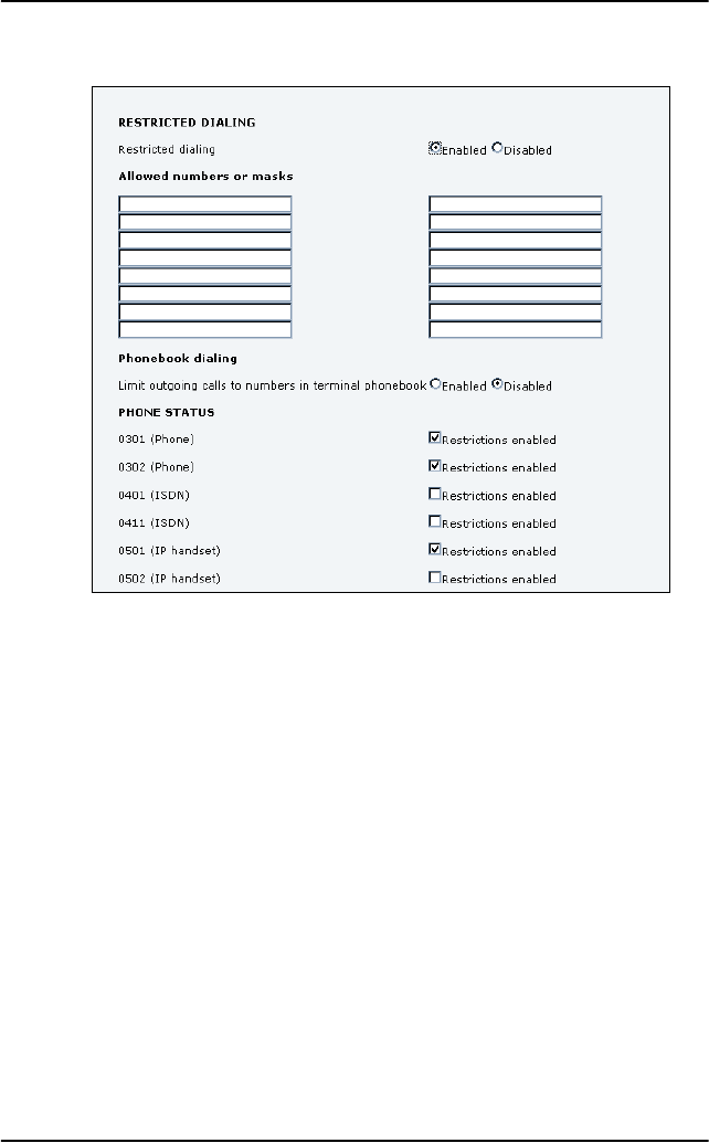
Chapter 5: System operation
188 Use the SBU web interface

189
Chapter 6
6666
Troubleshooting
Troubleshooting 6
In this chapter
In this chapter you can read about:
•Get support
•SDU errors
•SBU errors
•System LEDs
Get support
If this manual does not provide the remedies to solve your problem, you
may want to contact your service provider, your aircraft installation and
service center or your local distributor.
The web interface of the SBU provides a help desk, event logs and event
lists. The system can also generate a diagnostic report for service and
maintenance purposes.
Airtime support
If you need assistance from your service provider, call the help desk. To see
the help desk number, enter the web interface of your system and select
HELP DESK. This displayed help desk number is either taken from the SIM
card or entered manually. If no number is available under HELP DESK, check
the documentation of your service provider for a contact number.
System support
If you need assistance when solving problems caused by the system or
antenna, please call a distributor in your area. A list of certified partners and
distributors is available on Cobham SATCOM’s web site:
www.cobham.com/satcom. Select Technical Service Partner List.

Chapter 6: Troubleshooting
190 SDU errors
SDU errors
In case of a fault situation, first check that the LED for H+ (Classic Aero) in
the handset is lit, and that the display reads as shown below:
Also make sure that the transmission path is not obstructed, e.g. by
buildings if the aircraft is on the ground.
The AVIATOR 700 system has different means of status signalling:
•Error Messages. The AVIATOR 700 system is able to display various
error messages to help you troubleshoot the system. The following
sections provide an overview and a list of some of the error messages
you may see in the display.
•LEDs. For information on the LEDs on the handsets, see System LEDs
on page 206.
Furthermore, the SDU and HPA are equipped with LEDs for signalling
their status. These LED functions are described in the section System
LEDs on page 206.
When contacting your distributor for support please enclose a service log
for the SDU. A service log is generated using the Aero-SDU Configuration
Program. For further information see the AVIATOR 700 Installation and
Maintenance Manual.
Error messages
If there is a fault, the type of fault and the fault code is displayed in the Full
Feature handset. Where possible the fault code is translated into plain text.
Two types of fault codes are defined:
• BITE (Built-In Test Equipment) errors
•Cause Codes
For a complete list of BITE error codes and Cause Codes, please refer to the
Installation and Maintenance Manual.
I4 satellite logon ok I3 satellite logon ok
Ready
AMER AM #x
H+ SBB SW64
ok 0/1 ok

Chapter 6: Troubleshooting
SDU errors 191
6666
Troubleshooting
BITE errors
A BITE error is a hardware error detected by the built-in test equipment in
the SDU.
The red LED on the handset indicates the presence of a fatal or essential
BITE error.
•A fatal BITE error means that you are logged off and cannot log on
again.
•An essential BITE error means that the functions are limited and one
or more services are not available.
•A non-essential BITE error means that there are minor errors, but all
services are still available. The red LED on the handset will not indicate
this type of error.
Please report any BITE errors to the Maintenance Responsible.
When a BITE error is present, the display toggles between the active event
and the previous display contents.
The BITE error is shown in the second line of the display. A BITE error has a
unique 4-characters BITE code.
You can also view any active BITE errors in the Status menu under Active
Errors.
A list of BITE error codes is available in the AVIATOR 700 Installation and
Maintenance Manual.
Cause codes
A Cause Code describes a fault detected by the Earth Station during a call.
The cause codes can help you find the reason for an error. In most cases,
errors are caused by a problem in the satellite network.
The Cause Code is displayed in the handset for a few seconds after the call
is interrupted. If possible, the code is translated into plain text instead of
the Cause Code. A Cause Code is a unique 4-characters code.
The Cause codes are divided into two types:
Logon Reject cause codes and Call Reject cause codes.
• Logon Reject cause codes appear during logon attempts.
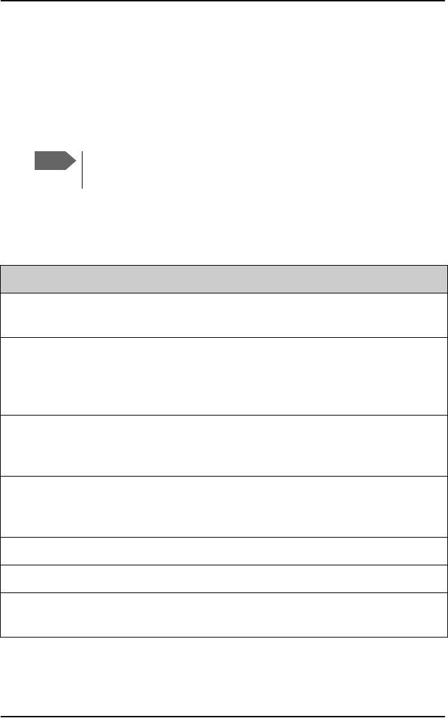
Chapter 6: Troubleshooting
192 SDU errors
• Call Reject cause codes appear after logon, during call attempts.
The following section shows the two lists of H+ cause codes with
explanations of the error messages.
List of H+ Cause codes
Logon Reject Cause Codes
The following list shows the cause codes that may appear during logon.
Note
Cause Codes should not be mistaken for BITE error codes. See the
previous page for an explanation of the two kinds of error codes.
Display Text ID Description Guidance
ClassReject 0x88 Class rejected The GES does not support
this class.
GlobChanLoss 0x82 Global channel loss Verify that there are no
obstacles between the
satellite and the AES
antenna.
GlobCunavlb 0x09 Global C channel
not available at
GES
ManualLogRej 0x89 Manual login
rejected
Manual logon is not allowed
when logon policy is
automatic.
NetworkFail 0x03 Network Failure
NoGesSignal 0x81 No GES signal
NoInitData 0x86 No valid system
table available

Chapter 6: Troubleshooting
SDU errors 193
6666
Troubleshooting
NoSatSignal 0x80 No satellite signal Verify that there are no
obstacles between the
satellite and the AES
antenna.
NotAuthorizd 0x0F AES not authorized Verify that the ICAO
address used is correct.
Verify that the ICAO
address is registered, by
contacting the service
provider.
OtherReason 0x0E Other Reason
OutsideCover 0x84 Outside spot beam
coverage
The AES is not under a spot
beam of the specified GES.
P/R/Tunavlb 0x07 Packet data
channel
unavailable
PkdtaUnavlb 0x08 Packet data service
unavailable
SatHandover 0x8C Satellite handover
SDUfailure 0x8A SDU failure Check the current BITE
errors.
SpotChanLoss 0x83 Spot channel loss
TableFull 0x00 Table Full
UserLogoff 0x87 User logoff
VCC&dUnavlb 0x0A Voice not available
at GES
VoiceUnavlb 0x01 Voice Unavailable
Display Text ID Description Guidance
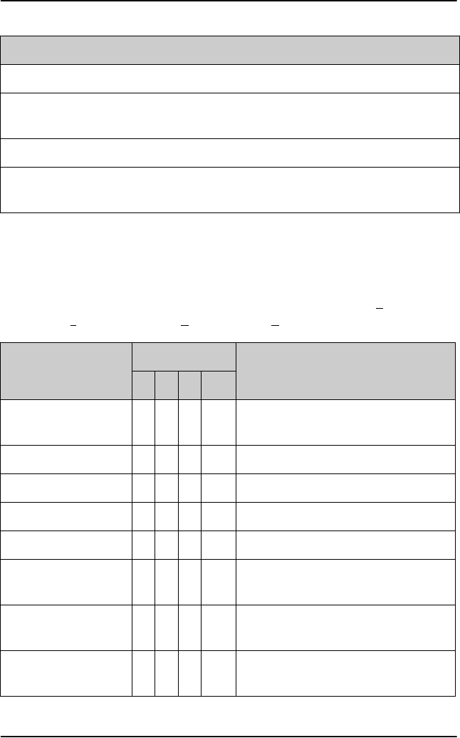
Chapter 6: Troubleshooting
194 SDU errors
Call Reject Cause Codes
The following list shows some of the cause codes that may appear when
the system is logged on. The SLCV codes refer to: S = coding Standard, L =
cause Location, C = cause Class, V = cause Value.
WrongGES 0x85 GES not existing Check GES ID validity.
WrongGESid 0x06 Wrong GES
identifier
Check GES ID validity.
WrongParam 0x02 Wrong Parameter
WrongSatID 0x05 Wrong Satellite
identifier
Check satellite ID validity.
Display Text ID Description Guidance
Display text
Code
Description
S L C V
0 0 1 0 0 0 1 0 Normal clearing by called/calling
party
1 1 7 15 1 1 7 15 Undefined cause
1 2 7 15 1 2 7 15 Undefined cause
1 3 7 15 1 3 7 15 Undefined cause
1 4 7 15 1 4 7 15 Undefined cause
AddrComplete 1 3 0 1 Address complete signal sent to
terrestrial network
AddrComplete 1 6 0 1 Address complete signal received
from terrestrial network
AESabsent 1 3 7 3 Calling/called AES not logged-on to
system
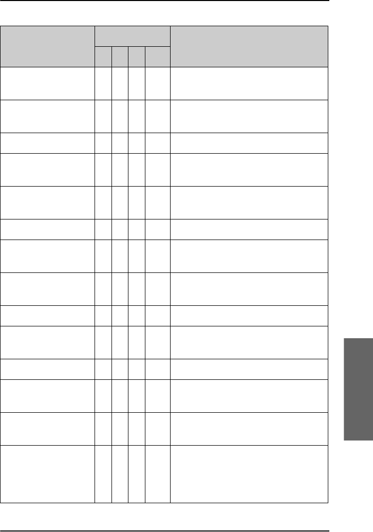
Chapter 6: Troubleshooting
SDU errors 195
6666
Troubleshooting
AnalogFail 1 4 2 3 Analog data equipment not
supported at GES
AnalogRate 1 4 6 2 Analog data rate not supported by
GES
CallBarred 1 4 4 3 Called AES barred for incoming calls
CallPreempt 1 1 1 1 Preemption by higher priority call at
AES
CardInvalid 1 3 6 1 Credit card type not supported by
GES
CardRejected 1 3 3 1 Credit card number rejected by GES
DigitalFail 1 4 2 4 Digital data equipment not
supported at GES
DigitalRate 1 4 6 3 Digital data rate not supported by
GES
Handover 1 3 7 4 Spot beam handover
InvalidAddr 1 2 3 2 Call Ann. / C-ch. Assign. not recd.
from GES
InvalidAddr 1 3 3 2 Incomplete called (AES) number
InvalidAddr 1 4 3 2 Invalid called number format
received from AES
InvalidNumbr 0 4 1 12 Incomplete called number format
from AES
Network busy 1 2 5 1 C-channel continuity test failure at
AES/
Connect acknowledge not received
by AES
Display text
Code
Description
S L C V

Chapter 6: Troubleshooting
196 SDU errors
Network busy 1 3 5 1 C-Channel continuity test failure at
GES/AES not responding/
Incomplete call information received
from AES/
Interruption in received AES carrier/
Connect acknowledge not received
by GES
NoAnswer 0 1 1 2 Expiry of answer time supervision at
AES
NoAnswer 0 4 1 2 Expiry of answer time supervision at
the MSSC
NoChanAvail 1 3 2 1 C-channel frequency/power
unavailable at GES
NoUnitAvail 1 2 2 2 C-channel unit unavailable at AES
NoUnitAvail 1 3 2 2 C-channel unit unavailable at GES
SatDestFail 1 1 4 1 Called AES terminal not in service
ServiceType 1 3 6 5 Service type not supported by GES
SwitchBusy 0 2 2 10 GES equipment congestion
SwitchBusy 0 4 2 10 GES equipment congestion/
No route to destination from GES/
Circuit to terrestrial network
unavailable
UnassignedNo 1 4 7 2 AES not authorized for service
Unauthorised 1 3 4 2 Calling AES not authorized for
service
UserBusy 1 1 7 1 Called AES terminal busy
Display text
Code
Description
S L C V
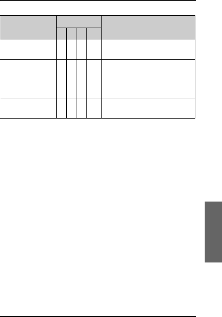
Chapter 6: Troubleshooting
SDU errors 197
6666
Troubleshooting
UserBusy 1 3 7 1 Call reference number unavailable at
GES
VoiceTypeErr 1 2 6 4 Required voice channel
characteristics not supported by AES
VoiceTypeErr 1 3 6 4 Required voice channel
characteristics not supported by GES
WrongNumber 0 4 0 1 Unallocated called number received
from AES
Display text
Code
Description
S L C V
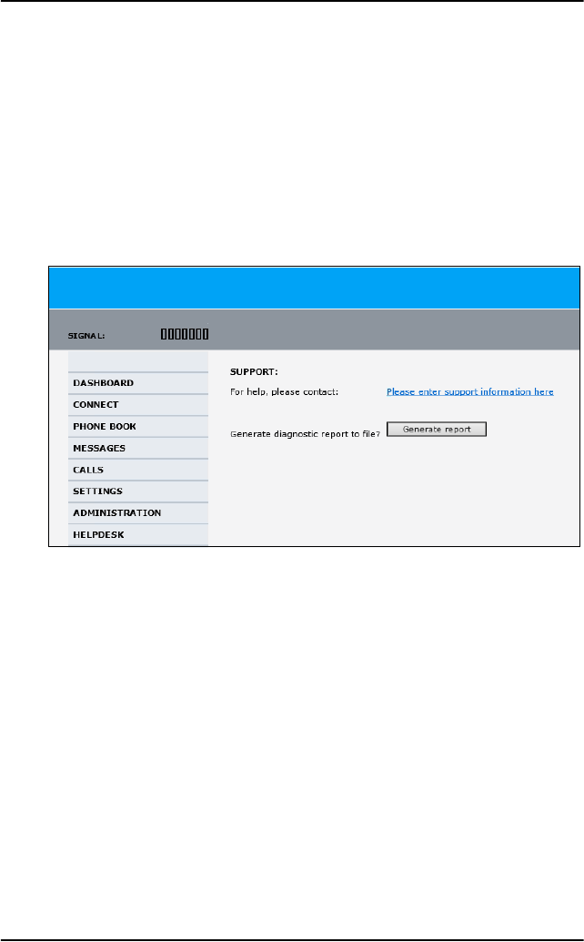
Chapter 6: Troubleshooting
198 SBU errors
SBU errors
Access the Help desk
If you need help with airtime-related issues you may call the Help desk.
By default, the Help desk is the phone number for your Airtime Provider, if it
is available on the SIM card.
To access the Help desk, select HELP DESK from the left navigation pane.
If the Help desk number is available on the SIM card, the number is
displayed as a link. To change the number, click the link, change the number
and click Apply.
If you need help with system or antenna related issues call your local
distributor.

Chapter 6: Troubleshooting
SBU errors 199
6666
Troubleshooting
Generate a diagnostic report
The SBU can generate a diagnostic report. This report contains information
relevant for the service personnel during maintenance and troubleshooting.
If you have reason to believe the system is malfunctioning you can
generate such a report, save it and send it to the system responsible.
To generate a diagnostic report with valuable information for the service
team, do as follows:
1. Reboot the system.
2. Establish the problem or situation in which the error occurred, or
3. Make a CS call (if possible), i.e. making a call with a handset connected
to the SBU.
4. Make a PC call (if possible), i.e. establish a data connection.
5. Click Generate report from the HELP DESK page.
In some browsers the file may open directly in your browser. If it does,
choose File > Save As to save the file.
6. Choose a location for the file and save it on your computer.
7. Send it to your system administrator.
Event log and self test
The SBU logs events and results from self tests. This information is useful
during maintenance and troubleshooting. For further information how to
view the event list and the event log and how to make a self test see the
AVIATOR 700 Installation and maintenance manual.

Chapter 6: Troubleshooting
200 SBU errors
SBU Troubleshooting guide
The below table provides information on some of the problems that might
occur, including possible causes and remedies to solve the problems.
Problem Possible Cause Remedy
No signal or
weak signal
from the BGAN
satellite.
The view to the
satellite is
blocked.
There might be some temporary
loss of signal due to parts of the
plane blocking for a clear view of
the satellite. This temporary loss
of signal will pass when the
antenna has a full view of the
satellite again.
The system is not
fully operational.
Wait until the system is powered
up and fully operational. There
might be an indicator in the
cabin indicating that the satcom
system is ready for use.

Chapter 6: Troubleshooting
SBU errors 201
6666
Troubleshooting
Connection to
the Internet
cannot be
established.
Your system is set
up to start a
connection in the
web interface
manually.
Open your Internet browser and
enter the default IP address of
the SwiftBroadband Unit:
http://192.168.0.1 (default
address). Click Start Standard to
open a standard data
connection manually. For more
details see Start or stop a
Standard connection on
page 110.
WLAN security
not set up
correctly.
Contact your system
administrator for encryption
keys for your Wireless interface.
No Wireless in the
cabin.
The wireless feature is not
enabled or not installed. Use a
LAN connection instead.
Your network user
group does not
allow Internet
access.
Contact the administrator to
change your network user group
to allow Internet access. You
might need to start a standard
data connection. For more
details see Start or stop a
Standard connection on
page 110.
Problem Possible Cause Remedy

Chapter 6: Troubleshooting
202 SBU errors
The web
interface
cannot be
accessed.
The browser of
your PC is
configured to use
a proxy server.
For Microsoft Internet Explorer,
select Tools > Internet
Options > Connections >
LAN Settings and uncheck
Use a proxy server for your
LAN.
You have entered
a wrong IP
address.
Check the IP address and re-
enter it. Default value:
http://192.168.0.1
Send a ping request in the
command prompt window.
If you do not have the correct IP
address, contact your system
administrator.
WLAN security
not set up
correctly.
Contact your system
administrator for encryption
keys for your Wireless interface.
No WLAN in the
cabin.
You try to make a connection
using WLAN, but there is no
WLAN antenna in the cabin. Use
a LAN connection instead.
You are
connected using a
VPN connection.
Close down your VPN
connection.
Problem Possible Cause Remedy

Chapter 6: Troubleshooting
SBU errors 203
6666
Troubleshooting
A Phone/Fax
connection
cannot be
established.
The phone cable
is not properly
connected.
Connect the phone cable.
The cable type or
connector type is
not correct.
For information on the correct
type of connector and cable,
refer to the installation manual.
Incoming calls:
The call type used
for the call is not
selected in the
web interface.
Make sure the call type used for
calls to the system is selected in
the web interface. Access the
web interface and select
SETTINGS > Phone/Fax.
Then, for each of the two ports,
select the call type for incoming
calls.
The fax machine
times out.
Set the fax machine to overseas
mode, allowing for longer time
intervals before timing out.
Problem Possible Cause Remedy

Chapter 6: Troubleshooting
204 SBU errors
An ISDN
connection
cannot be
established
The cable is not
properly
connected.
Connect the cable.
You have
connected to the
LAN interface.
Connect the cable to the
interface marked ISDN.
The cable type or
connector type is
not correct.
For information on the correct
type of connector and cable,
refer to the installation manual.
Incoming phone
calls: The call type
used for the call is
not selected in the
web interface.
Make sure the call type used for
calls to the system is selected in
the web interface. Access the
web interface and select
SETTINGS > ISDN. Then
select the call type for incoming
calls.
A LAN
connection
cannot be
established.
The cable is not
properly
connected.
Connect the cable.
You have
connected to the
ISDN interface.
Connect the cable to the
interface marked LAN.
The cable type or
connector type is
not correct.
For information on the correct
type of connector and cable,
refer to the installation manual.
Problem Possible Cause Remedy

Chapter 6: Troubleshooting
SBU errors 205
6666
Troubleshooting
An IP handset
connection
cannot be
established.
The built-in WLAN
option is not
enabled.
Have the WLAN option enabled
by your system administrator.
The passwords in
handset and
terminal do not
match.
Match the passwords. For
instructions see the user manual
for the AVIATOR Wireless
Handset.
The WLAN
encryption code
does not match.
Check that you have the correct
encryption code for accessing
the WLAN access point. The
encryption code is set up in the
web interface under SETTINGS
> WLAN.
The
administrator
password does
not work.
The administrator
password has
been changed.
If the correct password is not
found, you have to reset the
password.
Contact your system
administrator, then your supplier
for a reset code. You must
provide the serial number and
IMEI number of the
SwiftBroadband Unit.
Problem Possible Cause Remedy
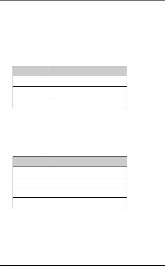
Chapter 6: Troubleshooting
206 System LEDs
System LEDs
SDU LEDs
SDU Power LED
The function of the power LED on the SDU is as follows:
SDU Logon LED (H+)
The Logon LED on the SDU shows the H+ logon status. The HSD logon
status is only signalled in the Full Feature handset.
The possible colors are listed below, with a short description of what they
indicate:
LED Color Description
Green Power OK
Orange Uploading software
Off No power
LED Color Description
Off No acquired satellite
Red Acquired a network satellite
Orange Network synchronization
Green Network logon
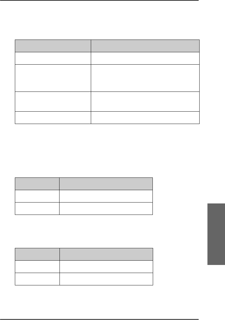
Chapter 6: Troubleshooting
System LEDs 207
6666
Troubleshooting
SDU Fail/Pass LED
The function of the Fail/Pass LED on the SDU is:
HPA LEDs
HPA Power LED
The function of the power LED on the HPA is as follows:
HPA Fail/Pass LED
The function of the Fail/Pass LED on the HPA is:
Behavior Description
Steady red Fail
Alternating: Short green /
long pause
Power On Self Test (POST) or
Person Activated Self Test (PAST) in
progress
Alternating: Long green/
short orange 0.5 Hz
No current failure, but a BITE failure/
warning is logged in the error log
Steady green No faults
LED Color Description
Steady green Power OK
Off No power
Behavior Description
Steady red Fail
Off No faults
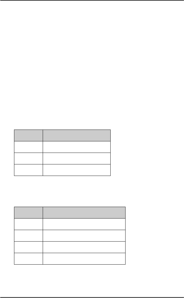
Chapter 6: Troubleshooting
208 System LEDs
SBU LEDs
During the power-up procedure all LEDs on the front plate are orange. If all
3 LEDs on the front stay orange after power up, there can be several
reasons:
• The SBU software is corrupted.
• The SBU Enable pin has not been wired properly in the installation. For
further information see the AVIATOR 700 Installation and Maintenance
Manual, chapter 5.3 Electrical installation and wiring, 5.3.2 Wiring SDU
to SBU.
SBU Power LED
The function of the Power LED on the SBU is:
SBU Logon LED
The function of the Logon LED on the SBU is:
Behavior Description
Green Power OK
Orange During upstart procedure
Off No power
Behavior Description
Red Acquiring satellite network
Orange Network synchronization
Green Network logon
Off No acquired satellite/logged off
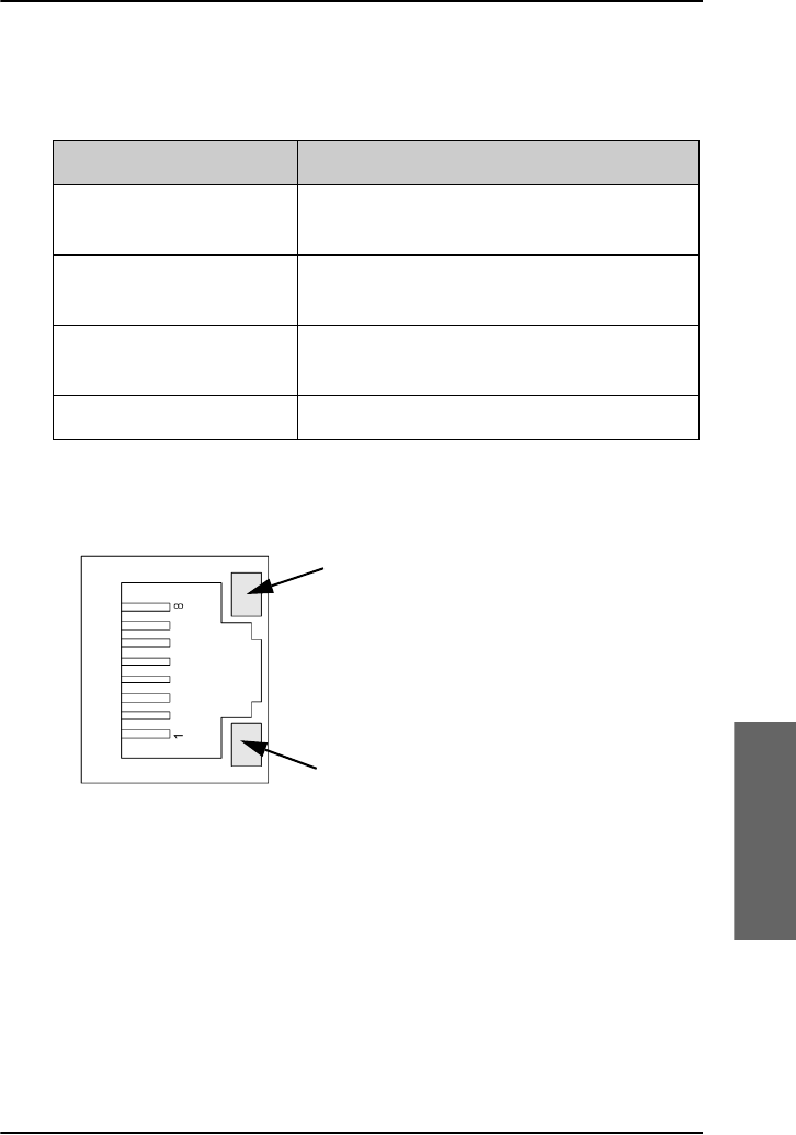
Chapter 6: Troubleshooting
System LEDs 209
6666
Troubleshooting
SBU Fail/Pass LED
The function of the Fail/Pass LED on the SBU is:
SBU LED on maintenance connector
The function of the LED on the maintenance connector is:
Behavior Description
Steady red A fault which may degrade the system
operation is present in the SBU
Flashing: short green/ long
pause
Power On Self Test (POST) or Person
Activated Self Test (PAST) in progress
Flashing: long green/ short
orange
No current failure, but a BITE failure /
warning is logged in the error log
Steady green No faults
Flashing yellow LED
Activity (data in/out)
Link (correct connection)
Steady green LED

Chapter 6: Troubleshooting
210 System LEDs

211
Appendix A
AAAA
Menu trees
Menu trees A
The next pages show an overview of the menu trees for the system:
•Menu tree for the Full Feature handset
•Menu tree for the MCDU
•Menu tree for the SBU
For details the menus, refer to the section Full Feature handset operation
(SDU) on page 113, MCDU operation on page 149 and Use the SBU web
interface on page 164.
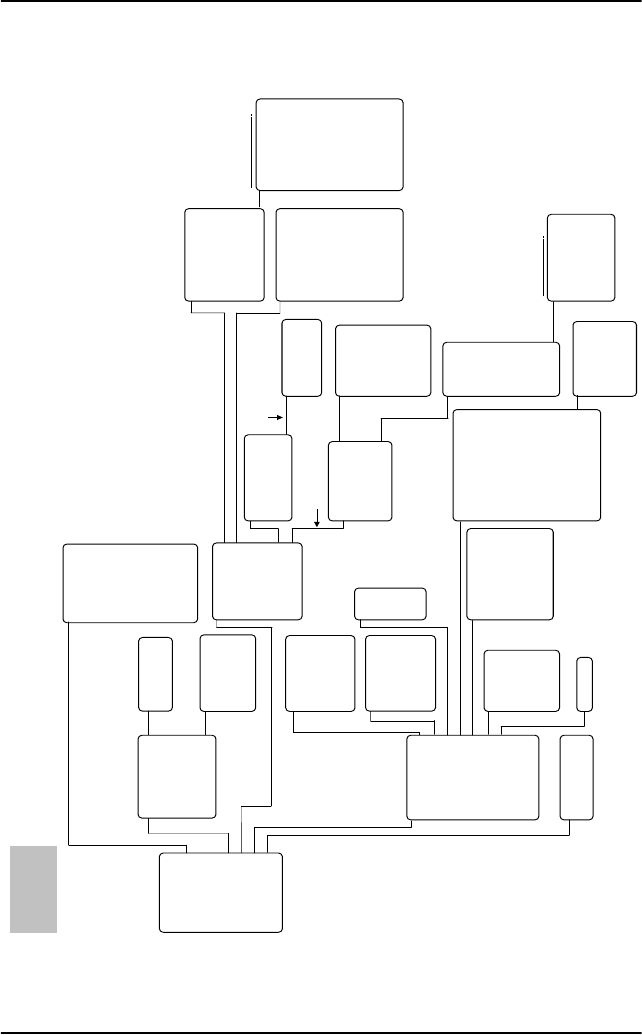
Appendix A: Menu trees
212
Menu tree for the Full Feature handset
5LQJ3URILOHV
4XLFN'LDO
'LVFORVH3RV
)D[6HWXS
3LQ6HWXS
&RQILJXUH
6LOHQFH
&RQWUDVW
/LJKW
.H\%HHS
6LQJOH5LQJ
&RPPRQ5LQJ
5LQJ9ROXPH
3KRQH9ROXPH
&RPI1RLVH
3KRQH%RRN
+DQGVHW6HWXS
5LQJ3URILOH
/RFN6\VWHP
/RJRQ0HQX
6\VWHP6HWXS
6WDWXV
0DLQWHQDQFH
/RJRQ3ROLF\
+*(6
,6'1/(6
03'6/(6
HPSW\!
HPSW\!
HPSW\!
HPSW\!
7DNH2I/DQGQJ
+DQGVHW
+DQGVHW
+DQGVHW
+DQGVHW
3276
3276
,6'1
$QQXQFLDWRU
$QQXQFLDWRU
$QQXQFLDWRU
HPSW\!
HPSW\!
HPSW\!
HPSW\!
HPSW\!
HPSW\!
HPSW\!
HPSW\!
HPSW\!
&KDQJH3LQ
'LVDEOH3LQ
(QWHU
3LQ&RGH
+DQGVHW7\SH
.QRZQ*(6V
.QRZQ/(6V
,QLW6DW
6DW
6DW
6DW
6DW
6DW
6DW
6DW
6DW
+DQGVHW
+DQGVHW
+DQGVHW
+DQGVHW
3276
3276
6DWHOOLWH,G
/RQJLWXGH
3&KDQQHO
3&KDQQHO
6HUYLFH3URYLGHU
3LQ&RGH
/RJRQ6WDWXV
6HUYLFHV
&KDQQHOV
1DY'DWD
,'V
6:9HUVLRQ
/$1
$FWLYH(UURUV
(UURU/RJ
/DWLWXGH
/RQJLWXGH
$OWLWXGH
6SHHG
1DY6RXUFH
,56$FWLYH
$+56$FWLYH
*36$FWLYH
6KRZ'HWDLOHG1DY
6KRZ$QWHQQD3RV
357
&
&
+6'
6%8
+HDGLQJ
3LWFK
5ROO
'RSSOHU9HO
6'86HU1R
+3$6HU1R
&06HU1R
+6'6HU1R
+6',61
,&$2
0DLQ
+DQGVHW
+DQGVHW
+DQGVHW
+DQGVHW
1RUPDO8VU3LQ
6XSHU8VHU3LQ
6HUY3UYGU3LQ
0HQXVIRUWKH)XOO)HDWXUHKDQGVHW
+
+6'
6%8
,ULGLXP
,ULGLXP
6'8/$1
+
+6'
6%8
,ULGLXP
,ULGLXP
0DQXDO/RJRQ
&XVWRP/RJRQ
$XWR/RJRQ
/RJRII
6HWWLQJV
,+6%%
,+6:
3UHVVWKHNH\
2.WRDFFHVV
WKHPHQXV
IRUHDFKVDWHOOLWH
IRUHDFK5LQJ3URILOH
0DLQWHQDQFH
5HVHW
RQO\LILQVWDOOHG

Appendix A: Menu trees
213
AAAA
Menu trees
Menu tree for the MCDU
0HQXVIRUWKH0&'86$7&20
ZLWKFRFNSLWDXGLRFRQQHFWHG
5,1*352),/(6
/2&.
/2*21
6<67(0
67$786
(037<!
(037<!
(037<!
(037<!
7$.(2)/$1'1*
1250$/
683(5
6(59,&(
/$7,78'(
/21*,78'(
$/7,78'(
63(('
1$96285&(
,56
$+56
*36
'(7$,/('1$9
$17(11$326
+($',1*
3,7&+
52//
'233/(59(/
0$18$/',$/
',5(&725<
68%0(18
35,25,7<
5(',$/
(0&21
0$18$//2*21
&86720/2*21
$872/2*21
/2*2))
6(77,1*6
$=,087+
(/(9$7,21
/2*21
6(59,&(6
&+$11(/6
1$9'$7$
,'6
6:9(56,21
/$1
$&7,9((55256
(5525/2*
+
+6'
6%8
,ULGLXP
,ULGLXP
RQO\LILQVWDOOHG
IRULQWHUQDOXVH
+
+6'
6%8
,ULGLXP
,ULGLXP
35()+*(6
35(),6'1/(6
35()03'6/(6
/2*2132/,&<
0,&
63($.(5
6,'(721(
6,/(1&(
&20)12,6(
.12:1*(6
.12:1/(6
,1,76$7
5,1*352),/(6
02',)<3,1
&21),*85(
7(&+1,&$/
5(6(7
+$1'6(77<3(
$8',2
$8',2
6$7(//,7(
',6&/26(326
)$;
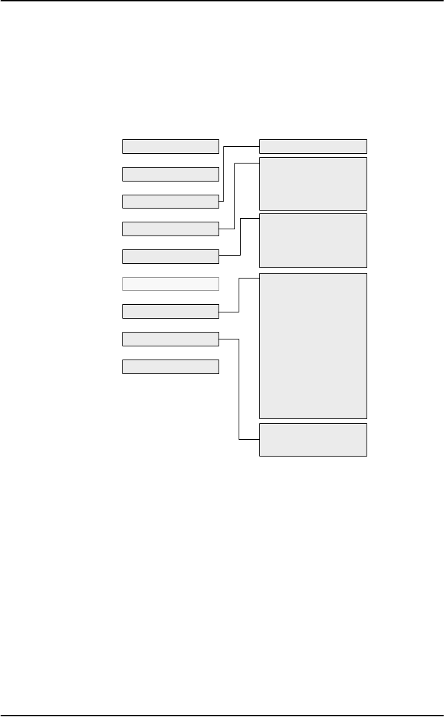
Appendix A: Menu trees
214
Menu tree for the SBU
The topics in gray are mainly used during installation and maintenance of
the system, they are described in detail in the AVIATOR 700 Installation
and maintenance manual.
0RELOHQXPEHUV
,QER[
:ULWHPHVVDJH
2XWER[
6HQW
0HVVDJHVHWWLQJV
2XWJRLQJFDOOV
5HFHLYHGFDOOV
0LVVHGFDOOV
6WDQGDUGGDWDVHVVLRQV
6WUHDPLQJGDWDVHVVLRQV
&DOOFKDUJHV
/RJKDQGOLQJ
'DWDOLPLWV
3URILOHV
7UDIILFIORZILOWHUV
6,03,1
6,0/RFN
8VHUSHUPLVVLRQV
5HPRWHPDQDJHPHQW
/LQNPRQLWRULQJ
5HPRWHDFWLYDWLRQ
5HVWULFWHGGLDOLQJ
0XOWLYRLFH
'$6+%2$5'
&211(&7
3+21(%22.
0(66$*(6
&$//6
6(77,1*6
$'0,1,675$7,21
+(/3'(6.
6,7(0$3
(YHQWOLVW
(YHQWORJ
6HOIWHVW

215
Appendix B
BBBB
List of available GESs
List of available GESs B
If you need to log on to a GES which is not in the list of known GESs, you
can use the Custom Logon function. See To make a custom logon on
page 125. When you make a custom logon, you need to enter the Sat ID
and GES ID for the GES you want to log on to. To find the Sat ID and GES
ID, you may use the list below. The following table shows a list of available
GESs supporting Classic Aero (H+).
Ocean Region Sat ID GES ID Name Abbr.
AORW 00 002 Eik (Burum) EK (BR)
AORW 00 005 Aussaguel (Burum) AS (BR)
AORE 01 067 Aussaguel (Burum) AS (BR)
AORE 01 068 Eik (Burum) EK (BR)
POR 02 130 Santa Paula (Perth) SP (PH)
POR 02 133 Perth (Perth) PH (PH)
IOR 03 193 Eik (Perth) EK (PH)
IOR 03 197 Perth (Perth) PH (PH)
MTSAT 04 161 MTSAT KH
APAC (I4) 05 080 Hawaii HW
EMEA (I4) 06 144 Fucino FC
AMER (I4) 07 208 Hawaii HW

Appendix B: List of available GESs
216

217
Appendix C
CCCC
Conformity
Conformity C
FCC
15.19 / RSS-GEN
NOTICE:
This device complies with Part 15 of the FCC Rules. Operation is subject to
the following two conditions:
1. this device may not cause harmful interference, and
2. this device must accept any interference received, including
interference that may cause undesired operation.
15.21
NOTICE:
Changes or modifications made to this equipment not expressly approved
by (manufacturer name) may void the FCC authorization to operate this
equipment.
15.105
NOTE: This equipment has been tested and found to comply with the limits
for a Class B digital device, pursuant to Part 15 of the FCC Rules. These
limits are designed to provide reasonable protection against harmful
interference in a residential installation. This equipment generates, uses and
can radiate radio frequency energy and, if not installed and used in
accordance with the instructions, may cause harmful interference to radio
communications. However, there is no guarantee that interference will not
occur in a particular installation. If this equipment does cause harmful
interference to radio or television reception, which can be determined by

Appendix C: Conformity
218 FCC
turning the equipment off and on, the user is encouraged to try to correct
the interference by one or more of the following measures:
• Reorient or relocate the receiving antenna.
• Increase the separation between the equipment and receiver.
• Connect the equipment into an outlet on a circuit different from that to
which the receiver is connected.
• Consult the dealer or an experienced radio/TV technician for help.
ICES-003
This device complies with Industry Canada licence-exempt RSS standard(s).
Operation is subject to the following two conditions:
(1) this device may not cause interference, and
(2) this device must accept any interference, including interference that
may cause undesired operation of the device.
Le présent appareil est conforme aux CNR d'Industrie Canada applicables
aux appareils radio exempts de licence. L'exploitation est autorisée aux
deux conditions suivantes:
(1) l'appareil ne doit pas produire de brouillage, et
(2) l'utilisateur de l'appareil doit accepter tout brouillage radioélectrique
subi, même si le brouillage est susceptible d'en compromettre le
fonctionnement.
NOTICE:
This Class [B] digital apparatus complies with Canadian ICES-003.
Cet appareil numérique de la classe [B] est conforme à la norme NMB-003
du Canada.

219
Glossary
DDDD
Glossary
Glossary D
A
ACARS Aircraft Communication Addressing & Reporting System
AES Aircraft Earth Station
AFIS Automatic Flight Information Service
AMER Americas (Satellite coverage)
ANSI American National Standards Institute, facilitates the voluntary
establishment of standards.
AORE Atlantic Ocean Region East (Satellite coverage)
AORW Atlantic Ocean Region West (Satellite coverage)
APAC Asia Pacific (Satellite coverage)
ARINC Aeronautical Radio, Incorporated
B
BGAN Broadband Global Area Network
BITE Built-In Test Equipment. A BITE error is a hardware error
detected by the automatic error detection system in the
satcom system.
Broadcast call A call that is made to all handsets simultaneously. The first
handset that replies establishes the connection, and the other
handsets are disconnected from the call.
C
C-Channel A bidirectional communications channel between ground and
air. C-channels are typically used for voice communications.

Glossary
220
CMU Communications Management Unit
CS Circuit-Switched. Circuit-switched networks require dedicated
point-to-point connections during calls.
D
DHCP Dynamic Host Configuration Protocol for assigning IP
addresses to devices on a network
E
EMEA Europe, Middle East, Africa (satellite coverage)
F
FNBDT Future Narrowband Digital Terminal. A US Government
standard for secure voice communication.
G
GES Ground Earth Station. Earth Station used to route satellite
communication using the H+ service.
H
HSD High-Speed Data
I
ICAO International Civil Aviation Organization. An ICAO address is a
unique 24-bit number assigned to an aircraft by the civil
aviation authority of the state in which the aircraft is registered.
IMEI International Mobile Equipment Identity. A unique number
identifying your terminal

Glossary
221
DDDD
Glossary
IMSI International Mobile Subscriber Identity)
IMSO International Mobile Satellite Organisation. An
intergovernmental organisation that oversees certain public
satellite safety and security communication services provided
via the Inmarsat satellites.
IOR Indian Ocean Region (Satellite coverage)
ISDN Integrated Services Digital Network
ISN Inmarsat Serial Number
ISP Inmarsat Service Provider
L
LAN Local Area Network
LCD Liquid Crystal Display
LED Light Emitting Diode
LES Land Earth Station. Earth Station used to route satellite
communication using the HSD service.
M
MB Mega Bytes
MCDU Multifunction Control and Display Unit. Part of the Flight
Management System.
MPDS Mobile Packet Data Service
MTSAT Satellite service, Classic Aero only

Glossary
222
N
NAT Network Address Translation, handles the conversion of the
public WAN IP to 253 private LAN IPs.
P
PAST Person Activated Self Test
PBX Private branch exchange, a telephone exchange that serves a
particular business or office.
P-Channel A channel which provides a unidirectional dedicated
communications channel from a GES to all aircraft. Data
packets are broadcast over this channel and addressed to a
specific aircraft.
PIN Personal Identification Number
POR Pacific Ocean Region (Satellite coverage)
POST Power On Self Test
POTS Plain Old Telephony System. Traditional 2-wire system.
PS Packet-Switched. Packet-switched networks move data in
separate, small blocks (packets) based on the destination
address in each packet.
R
RDI Restricted Digital Information
RTCA Radio Technical Commission for Aeronautics

Glossary
223
DDDD
Glossary
S
SBB SwiftBroadband. Simultaneous voice and broadband data up to
432kbps per channel.
SMS Short Messaging Service
STU Secure Telephone Unit
SW Software
T
TCP Transmission Control Protocol. One of the core protocols of the
Internet protocol suite. TCP provides reliable, in-order delivery
of a stream of bytes, making it suitable for applications like file
transfer and e-mail.
U
UDI Unrestricted Digital Information
UTC Coordinated Universal Time. The International Atomic Time
(TAI) with leap seconds added at irregular intervals to
compensate for the Earth’s slowing rotation. Leap seconds are
used to allow UTC to closely track UT1, which is mean solar
time at the Royal Observatory, Greenwich.

Glossary
224

225
Index
EEEE
Index
Index E
Numerics
2.4GHz Cordless
phone system, 13
2nd functions
Full Feature handset, 68
2-wire interface
local numbers, SBU, 53
local numbers, SDU, 40
3.1 kHz audio, 22
64 kbps
UDI, 22
A
access levels, 114
activation
remote, 185
activation SMS, 186
active error, SDU, 148
adding
GES, known, 140
GES, preferred, 128
ISDN LES, preferred, 129
LES, known, 141
MPDS LES, preferred, 129
phone book entry, SDU, 116
additional numbers
enter, 175
AHRS active, 146
airtime
unintended user of, 107
alarm
view active, SDU, 148
view log, SDU, 148
allowed numbers
restricted dialing, 187
alpha mode, key functions, 70
alpha-numeric keys
Full Feature handset, 69
altitude, 146
analog phone
local numbers, SBU, 53
local numbers, SDU, 40
annunciators
SDU, 135
answering a call
2.4GHz Cordless handset, 80
Sigma7 handset, 79
Thrane & Thrane handsets, 71, 76
antenna
viewing status, 171
viewing type, 171
antenna position, 146
applications, 1
audio quality, 34, 46
automatic shut down
connection, 181
Auxiliary cradle, 12
Auxiliary handset, 12
B
BITE error codes, 191
booting, 25
broadcast ringing tone
disabling for selected interfaces, 132
browser settings
for web interface, 165

Index
226
C
call
answering, 71, 76
forwarding, SBU, 58
from Auxiliary handset, 73
from Full Feature handset, 71
from POTS handset, 73
holding, MCDU, 92
holding, SBU, 56
holding, SDU, 41
incoming, in MCDU display, 84
local, MCDU, 90
local, SBU, 52
local, SDU, 39
making or receiving, SBU, 49
making or receiving, SDU, 37
manual, MCDU, 88
missed, received, outgoing, SBU, 177
priority, MCDU, 90
Quick dial, Full Feature handset, 72
redial, SBU, 53
to the SBU, 51
to the SDU, 38
transfer, Full Feature handset, 41
transferring, MCDU, 92
transferring, SBU, 57
using ISDN, 80
using phone book, Full Feature
handset, 72
viewing ongoing, SBU, 172
waiting indication, SBU, 55
call costs
SIP-enabled IP phone, 81
call limiting, 187
call log, SBU, 176
call priority
MCDU, 150
call type, 34, 46
override, SBU, 47
call type H+, 36
call type HSD, 36
Caps toggle, 69
Cause codes, 191
list of, 192
certification level
SBU software, 172
SDU software, in 4w handset, 147
SDU software, MCDU view, 160
change PIN code, 137
channels
signal strength, 145
charges
SIP-enabled IP handset, 82
Classic Aero call
air to ground, 71
clearing logs, SBU, 180
clearing usage counter, SBU, 180
codec priority, 82
Comfort Noise, 121
commissioning, 24
conference call
MCDU, 93
SBU, 57
SDU, 42
configuration, 138
conformity, 217
connection
activate, 110
automatic shut down, 181
contact information, 189
contrast, LCD, 119
cordless phone, 13

Index
227
EEEE
Index
D
dashboard, 170
data limit
automatic shutdown, 181
data limits, 181
data sessions
standard, SBU, 177
streaming, SBU, 177
viewing ongoing, SBU, 172
DDI numbers, 38
deactivation SMS, 186
default IP address, 106
delete
known GES, 140
known LES, 141
phone book entry, SDU, 116
preferred GES, 128
preferred ISDN LES, 129
preferred MPDS LES, 129
Quick dial entry, Full Feature handset,
135
ring profile, 134
satellite from list, 142
detailed navigation, 146
dial
numbers in phone book, SBU, 53
dialing prefixes, SBU, 54
dialing restrictions, 187
Direct Dial-In, 38
directory, MCDU, 90
disable PIN code, 137
disclose position, 132
display, handset
symbols, 64
display, MCDU, 83
symbols, 84
DO-178B level, v, vi
DO-254D level, v, vi
document number
related manuals, vi
this manual, i
doppler velocity, 146
E
edit
GES in known list, 141
LES in known list, 142
phone book, SDU, 116
Quick dial entry, Full Feature handset,
136
satellite information, 142
EMERGENCY
call priority, 150
error
log, SDU, 148
view active, SDU, 148
error codes, 190
BITE, 191
Cause codes, 191
list of, 192
exchange
local, 182
external IP address, 183
F
Fail/Pass LED
HPA, 207
SBU, 209
SDU, 207
fault
view active, SDU, 148
view log, SDU, 148

Index
228
fax
how to use, SBU, 46
how to use, SDU, 34
fax setup, 132
fax type H+, select, 36
fax type HSD, select, 36
fax, H+ service, 21
fax, sending or receiving, SBU, 60
fax, sending or receiving, SDU, 44
FCC compliance, 217
features of AVIATOR 700, 4
Flex key for options, 8
forwarding calls, SBU, 58
Full Feature cradle, 11
Full Feature handset, 11
function keys
Auxiliary handset, 74
Full Feature handset, 65
MCDU, 85
G
G3 fax machine, 34, 46
G4 fax or data, SBU, 46
G4 fax or data, SDU, 34
geostationary satellites, 15, 16
GES, 18
list of known, 140
list of preferred, 128
priority, 128
GPS Active, 146
H
H+ fax, 21
H+ modem, 21
handset setup, 117
handset type, 140
heading, 146
help desk number
changing in web interface, 198
help desk number, SBU, 198
holding a call, SBU, 56
holding a call, SDU, 41
HPA, 10
HSD call
ground to air, 39
ISDN air to ground, 80
I
ICAO address, 147
IMEI number, 171
IMN number, 39
Inbox for SMS messages
replying, forwarding or deleting, 98
incoming call
in MCDU display, 84
Inmarsat, 15
interfaces, 6
LAN and WLAN, SBU, 104
internal calls, SBU, 52
internal calls, SDU, 39
Internet
connecting a PC, 101
IP address
BGAN network, 183
default, 106
external, 183
for web interface, 167
local, viewing, 171
IP handset, 12
SIP, 81
IRS active, 146

Index
229
EEEE
Index
ISDN
local numbers, SBU, 53
local numbers, SDU, 40
phone call, 80
ISDN phone, 34
ISDN plug
SBU, 46
SDU, 34
ISN, 147
K
key beep, 120
keys
Auxiliary handset, 74, 75
Full Feature handset, 65, 69
MCDU, 85
L
LAN
managing network users, 104
LAN status, SDU, 147
latitude, 146
LCD, MCDU, 83
LEDs on SBU
Fail/Pass, 209
Logon, 208
Maintenance connector, 209
Power, 208
LEDs, handsets
Auxiliary handset, 73
Full Feature handset, 63
LEDs, system, 206
Fail/Pass, HPA, 207
Fail/Pass, SDU, 207
logon, SDU, 206
Power, HPA, 207
Power, SDU, 206
LES, 18
list of known, 141
list of preferred, ISDN, 129
list of preferred, MPDS, 129
priority, 129
light in handset, 119
limit
allowed MB, 181
data, 181
streaming class, 181
limit calls, 187
limiting data, 181
local call
MCDU, 90
SBU, 53
local exchange, 182
local numbers assigned, SBU, 53
local numbers assigned, SDU, 40
local phone call, SBU, 52
local phone call, SDU, 39
lock system
for one handset, 123
log
errors, SDU, 148
logoff, Full Feature handset, 126
logon
automatic, SDU, 126
custom, Full Feature handset, SDU,
125
Full Feature handset, SDU, 124
LED in handset, 64
LED on SDU, 206
manual with Full Feature handset,

Index
230
SDU, 125
policy, 128
settings, 126
Logon LED
on SBU, 208
logs, clearing, SBU, 180
longitude, 146
M
MAC address, 105, 171
Maintenance connector
LED, 209
manual
document number, i
manuals
other, vi
MCDU
display, 83
function keys, 85
making a call, 88
making or receiving a call, 87
memory
Auxiliary handset, 76
menu tree
SBU, 102
menu, handset
accessing, 114
entering selected, 114
exiting, 114
scrolling through, 114
shortcuts, 114
tree, 212
menu, MCDU
accessing, 86
navigating, 84
overview, 150
tree, 213
messages
configuring outgoing, 99
forwarding, 98
opening in web interface, 98
receiving in web interface, 97
replying, 98
sending, 96
missed calls, SBU, 177
mobile numbers for SBU
viewing and editing, 175
modem, H+ service, 21
MPDS, 22
multi-party call, SBU, 57
Multi-voice, 175
N
navigation
data, 146
show detailed, 146
speed, 146
navigation in web interface, 169
Navigation source, 146
Network Coordination Stations (NCS),
15
network management, 104
network user group, 105
NON-SAFETY
call priority, 150
non-safety interfaces, 8
Normal User, 114
PIN code, 136
numeric keys
Auxiliary handset, 75

Index
231
EEEE
Index
O
Outbox for SMS messages
resending or deleting messages, 95
outgoing calls, SBU, 177
override
call type, SBU, 47
P
packet data
H+, 22
high speed, 22
password
SIP phone, 82
PC
connecting to the Internet, 101
phone
how to use, SBU, 46
how to use, SDU, 34
local call, SBU, 52
local call, SDU, 39
making calls, SBU, 49
making calls, SDU, 37
phone book, 173
delete entry, SDU, 116
edit entry, SDU, 116
Full Feature handset, making a call,
72
insert new entry, SDU, 116
limited numbers, 187
making a call, SDU, 116
phone book, MCDU, 90
phone book, SBU
adding number, 174
deleting all entries, 175
deleting an entry, 174
modifying an entry, 174
phone book, SDU, 115
phone number, 175
phone numbers for SBU, 175
phone volume, 121
Phone/Fax interface
local numbers, SDU, 40
local, SBU numbers, 53
PIN code
normal, 136
Service, 136
Super, 136
PIN codes
changing, 137
pitch, 146
POTS phone, 73
Power LED
HPA, 207
on SBU, 208
SDU, 206
prefixes, special-purpose, SBU, 54
priority
change for GES, 128
change for ISDN LES, 129
change for MPDS LES, 129
of phone numbers, MCDU, 90
profiles, 104
properties
system, 171
Proxy server, disabling, 165
PUBLIC
call priority, 150
Q
quality of voice, 34, 46

Index
232
Quick dial
edit entry, Full Feature handset, 136
Full Feature handset, 135
making a call, Full Feature handset,
72
Quick dial, SBU, 49
R
radiation warning, iii
Realm, 82
received calls, SBU, 177
redial
Auxiliary handset, 78
Full Feature handset, 72
SBU, 53
reduce airtime cost, 107
remote activation
by SMS, 186
trusted mobile number, 186
remote control, 185
remote management
accessing, 184
preparation, 183
SBU, 183
reset, 148
restricted dialing, 187
ring profile
defining, 133
selecting, 122
ring tone
all handsets, 120
broadcast call, 120
current handset, 120
direct call, 120
ring volume, 121
ringmode
defining, 133
selecting, 122
roll, 146
router functionality, 8
S
SAFETY
call priority, 150
safety summary, iii
SATCOM MAIN, 86
SATCOM subsystem, 86
satellite
view selected, 171
satellites
footprint, 16
Inmarsat, 15, 16
list of, 142
SBU
accessing the web interface, 167
remote control, 183
Scratch Pad
MCDU, 83
SDU, 9, 34
serial number, 147
SDU errors, 190
seat-to-seat
dialing, SBU, 53
sent messages
resending, forwarding or deleting, 96
viewing status, 96
serial number, 171
serial numbers
viewing, 147
Server name
SIP server, 82
service log, 190

Index
233
EEEE
Index
Service Provider, 114
PIN code, 136
services
view availability, 145
services supported, 21
Short dial, SBU, 49
Sigma7
handset and cradle, 12
signal strength, 145
Silent function, 119
SIP client, 81
SIP server
codec priority, 82
connect to, 81
name, 82
password, phone, 82
realm, 82
SIP-enabled IP handset
server name, 81
setting up, 81
using, 82
site map
SBU web interface, 102
SMS
activation, 186
deactivation, 186
SMS activation, 186
SMS in web interface
forwarding, 98
opening, 98
receiving, 97
replying to, 98
sending, 96
SMS service center
number, 99, 100
software
viewing version, 171
software version, v, 147
SBU Level D, vi
SBU Level E, v
SBU software, 172
SDU Level D, vi
SDU Level E, v
SDU, 4w handset view, 147
SDU, MCDU view, 160
speaker volume, 121
special characters, 69
Speech, 22
spot-beams, 16
Standard data
activating, 110
standard data sessions, SBU, 177
Standard IP
activate, 110
Standard IP data connection, 109
standard voice
phone number, 175
status, 143
ongoing calls and data sessions, SBU,
172
viewing, 170
storing a phone number
Auxiliary handset, 76
streaming class
time limit, 181
streaming connection
stop, 112
streaming data sessions, SBU, 177
Streaming IP data, 109
streaming rates, 111
Super User, 114
PIN code, 136
supplementary services, SBU, 55
support
contact information, 189
SW version, 147

Index
234
Swift64 data connection, 112
SWIFT64 numbering, 39
Swift64 service, 16
switchboard, MCDU, 91
system reset, 148
system setup, 130
T
TCP/IP traffic, 109
telephone interface
local numbers, 53
local numbers, SDU, 40
To, 173
tools for setting up the SBU, 101
total usage
viewing, SBU, 172
total usage, SBU calls
viewing, 176
transferring a call
Full Feature handset, 41
SBU, 57
troubleshooting, 190
troubleshooting guide, 200
trusted mobile number, 186
typography used in this manual, vi
U
usage counter
clearing, SBU, 180
usage counter, SBU, 172
usage counter, SBU calls, 176
user interfaces, 101
user name
SIP server, 82
V
version of software, 171
voice
H+, 21
HSD, 22
voice mail, 30
number, 99
number, SBU, 178
voice mail for SBU, 52
voice quality, 34, 46
volume
phone, 121
W
waiting calls, SBU, 55
warning
radiation, iii
web interface, 14
accessing, 164
browser settings, 165
navigating, 169
Wireless, 8
Wireless Handset and Cradle, 12
wireless IP handset, 81
WLAN option, 8
world map with satellites, 17

98-130578-D
www.cobham.com/satcom