Thrane and Thrane A S RTU4120B Iridium fixed mount transceiver User Manual M4150GB0 1 pre
Thrane & Thrane A/S Iridium fixed mount transceiver M4150GB0 1 pre
UserManual.wiki
>
Thrane and Thrane A S
>
RTU4120B User Manual
>
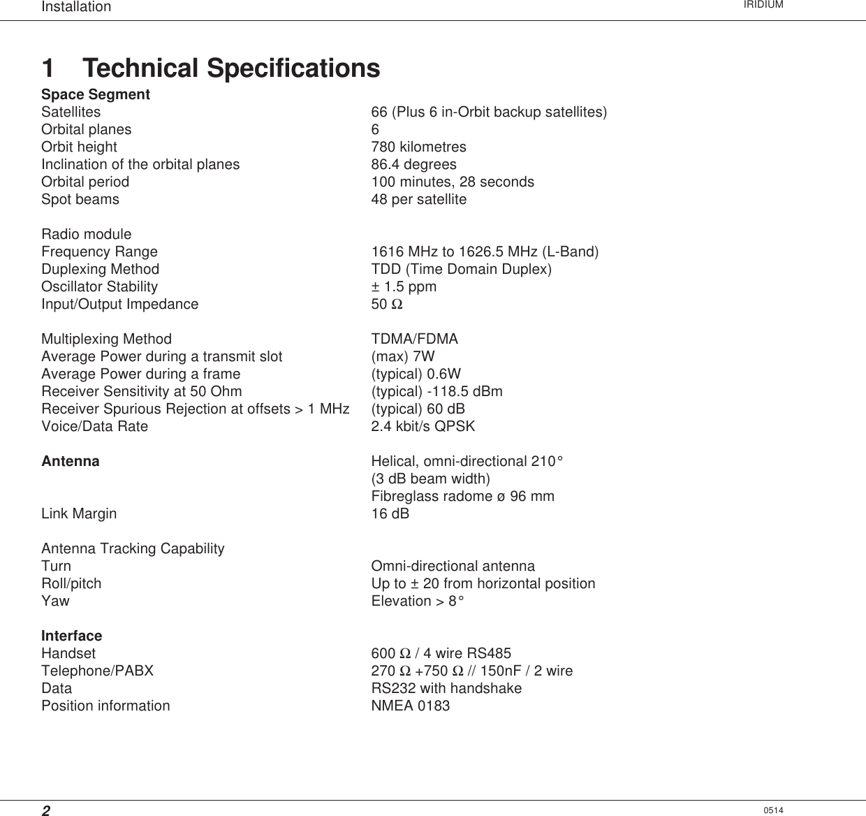
technical manual
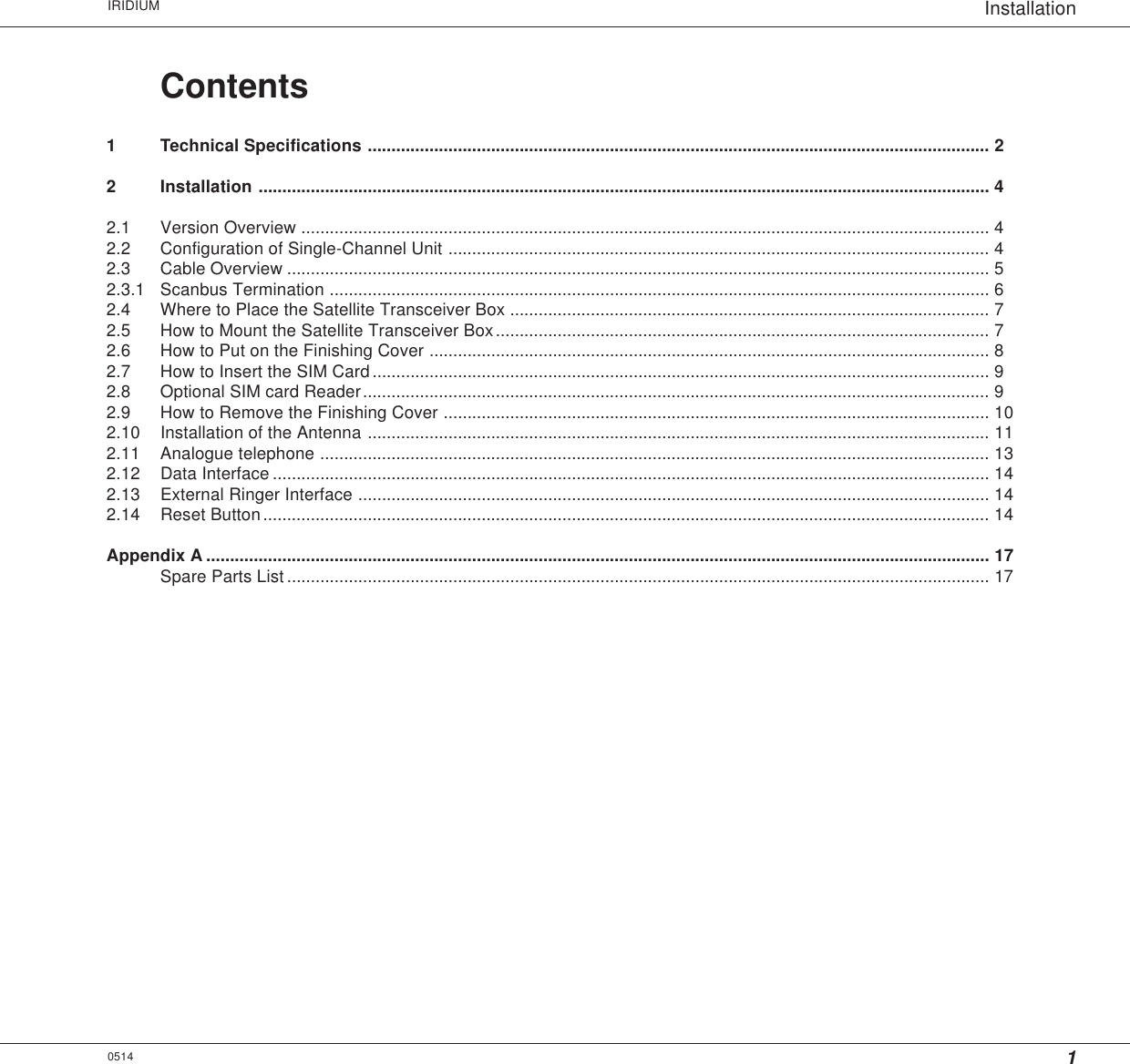
Contents
1.
user manual
2.
technical manual
technical manual
Navigation menu
Upload a User Manual
Namespaces
Wiki Guide
HTML
PDF
Info
Views
User Manual
Discussion / Help
Navigation