Three In One TIO-W355558100 Wireless Video Scope User Manual 01
Three In One Enterprises Co., Ltd Wireless Video Scope 01
User Manual

Video Scope User Manual
For Model:TIO-W3558100

Table of contents
Safety recommendations ..............................................................................3
1. Description................................................................................................4
2. Preparation for use ...................................................................................5
3. Menu set up ..............................................................................................6
7. Snapshot and Recording functions................................ ..........................10
10. Troubleshooting......................................................................................11
11. Technical data. .......................................................................................11
12. Spares & accessories.............................................................................13
VIDEO SCOPE
8. Surfing mode............................................................................................10
4. Digital Zoom................................ ..............................................................8
5. LED Adjustment................................ ........................................................9
6. Mirror / Reflecting Object Surface.................................. ...........................9
9. Transferring Photos and Videos to a PC..................................................11
Safety recommendations
Warning
• Do not modify or disassemble the unit.
• Do not use this item in explosive atmospheres.
Caution
• Keep the device out of the reach of children.
• Do not look directly into the objective lens at the end of the insertion
tube, your eyesight may be seriously damaged.
• Do not forcibly bend, twist or elongate the insertion tube.
• Strong impact on the device may result in the breakage of the objective
lens (made of glass) at the tip of the insertion tube.
• Do not use or store the device at a temperature higher than 60 °C or
lower than -20 °C.
• Don’t use the device in the direct sunshine.
• Store the device in a dry and adequately ventilated environment.
• Keep the device away from acid or alkaline solutions, oil or petrol, and do
not use it in an atmosphere containing their vapours.
• Do not remove the SD Memory Card while data is being saved to the
card. This may cause the data to be lost or the card to be damaged.
3
VIDEO SCOPE
Warming:
Changes or modifications are not expressly approved by the manufacturer
could void the user's authority to operate the equipment
4
1. Description
VIDEO SCOPE
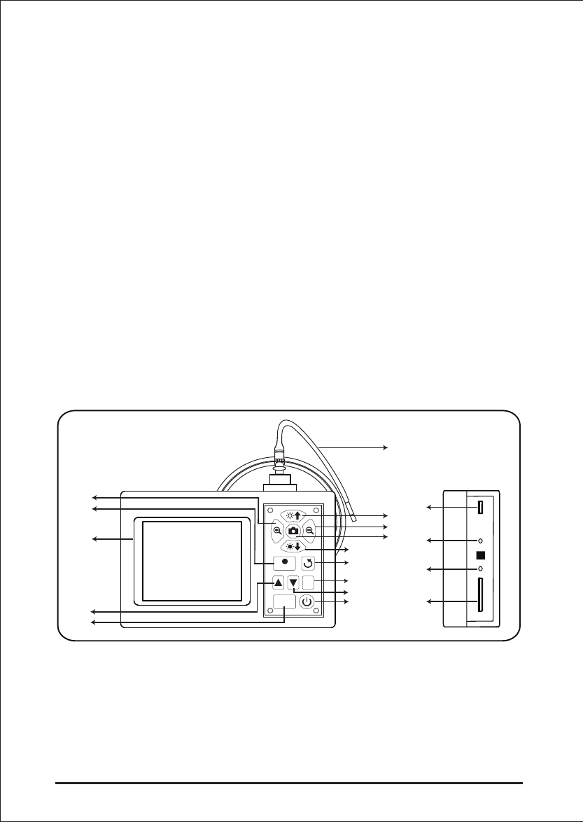
Parts and function
A. POWER button
C. Escape
B. DOWN button
G. Zoom out
L. Display unit
E. LED brightness decrease
M. REC button
D. Mirror Image and Rotate J. OK button
K. UP button
N. Zoom inH. LED brightness increase
F. PHOTO button
O. SD slot
Q. Video Out
P. DC-in
R. USB Port
I. Insertion tube
This wireless Video Scope is a compact handheld instrument that allows the user to view
applications in restricted spaces that could not normally be seen with the naked eye.
This wireless Video Scope is supplied in a sturdy carrying case and consists of a display unit,
insertion ube, main adapter and side view adapter. The display unit, with a 3,5” wide angle
TFT LCD screen, has the capacity of viewing, storing and reviewing photos and video images.
Images can also be displayed directly on a TV screen or stored and transferred to a PC
for viewing later. The display unit is powered by rechargeable Li-polymer batteries and a
multi-voltage charger is included. The 1 meter (3,3 ft) insertion tube has a tip of just
5,5 mm (0.22 in) and is equipped with powerful variable LED lighting. Other lengths are
available, see section 12. Spares & accessories.
Wireless Inspection System Introduction and Applications
Wireless Inspection System is an outstanding feature of Video Scope. The wireless inspection
camera lets you see a clear image of problems in hard to reach locations without the cable.
The image can be sent to main unit up to 50 m (160') away. With the palm-sized probe handle
you can inspect many applications. Video Scope includes wireless and direct input modes.
You can choose the appropriate mode to meet your needs in different working applications.
You can hold the wireless probe handle at a perfect height when checking somewhere
unreachable and narrow、dark space. In some special working environments you may need
a free hand to remove an obstacle during inspection. Simply place the main unit on a stable
platform and manipulate the probe with a single hand. Besides, we can have a long time
inspection away from the target observed with Wireless Inspection System if the probe handle
is set up fixed.
Rec
Eec
OK
A
B
C
D
E
F
G
H
I
J
K
L
M
N
O
P
Q
R
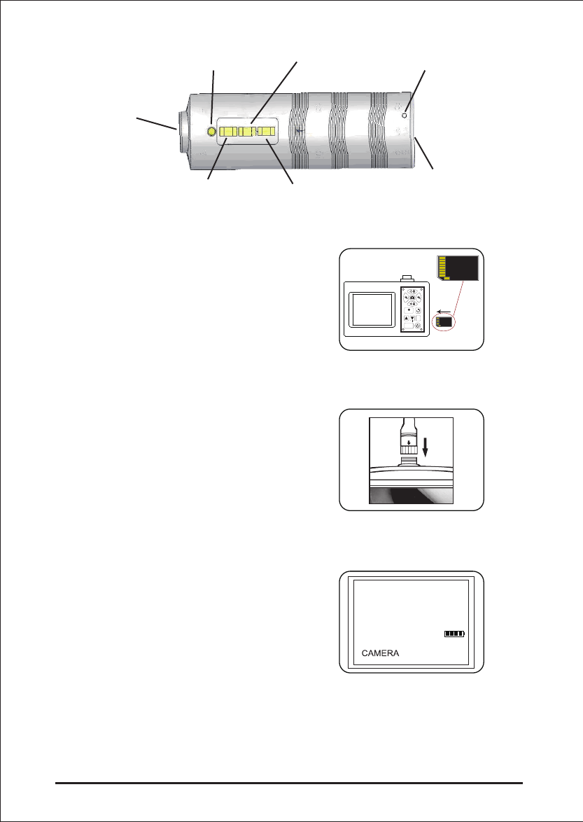
2. Preparation for use
On first use it is important that the
SD card is inserted as Fig.1 shown.
Connect the insertion tube to the display
unit as shown in the figure and tighten
the locking collar:Fig.2
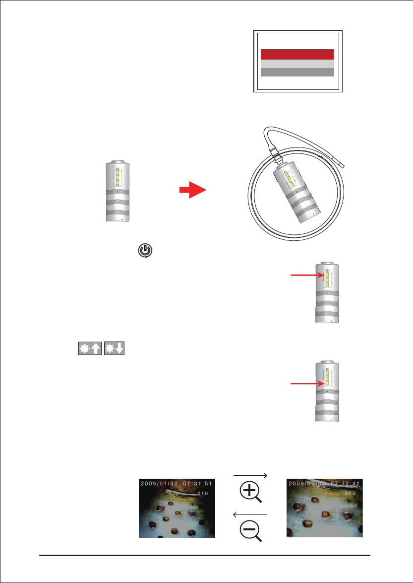
The status screen shows the capacity of the SD card and the internal battery.
If the Video Scope has been stored for a long time then the display might not able to turn on.
The most likely cause is that the battery has run out.Please use power adapter to re-charge
the battery.
5
VIDEO SCOPE
Press the POWER button for 3-5
seconds to turn the display unit on.
The Start-up screen is shown briefly
followed by the status screen for five
seconds.Fig.3
Fig.2
Fig.3
Wireless Inspection Device Parts and Function
Insertion tube
Connector
Power ON/OFF
botton
Battery charge
indicator LED
Battery charger
connector
Power Indicator LED LED brightness increase
LED brightness decrease
Fig.1
Rec
Eec
OK

Directly on the screen, a “live” picture can be seen. This is the camera mode.
• Switch the unit on. Ensure that camera mode is active (i.e. a “live” picture can be seen)
• Press the OK button to access the menus. Use the UP or DOWN button to select the
menu item. Press OK to confirm.
3. Menu set up
The options displayed are as follows;
- Delete all
- Video output
- Date / time setup
- Language
- Video format
- Auto power off
- Input Source
Delete All
Take care in selecting this option, as everything will be deleted from the SD card!
Navigate to DELETE ALL in the menu, press the OK button. Select YES or NO using the
UP or DOWN buttons. Confirm with the OK button.
It is strongly advised to properly set-up the Video Scope before first use. The indexing of
saved photos and video is based on date and time only. Other parameters, if set before
first use, can make the operation of the Video Scope easier in the future.
Press POWER button for 3-5 seconds to turn the display unit off.
The side view adapter included, is ideal for viewing pipe walls.
To fit the side view adapter, unscrew the chrome tip of the insertion tube and replace with
the side view adapter.
6VIDEO SCOPE
Video Output
This function allows live pictures or recorded photos and videos to be displayed on a
TV screen or beamer. First make sure that the Video format is set correctly to the used
TV system (PAL or NTSC). (See the Menu set up section.)
Connect the scope video cable to the display unit TV out jack. Ensure that the other end of
the video cable is well connected to the TV or beamer.
Press the OK button to select menu options, select Video Output and press the OK button.
The scope unit screen will turn black and the display will be shown on the TV. You can
transfer the screen back to the display unit by selecting the same function.
Confirm selection and exit menu by pressing OK.
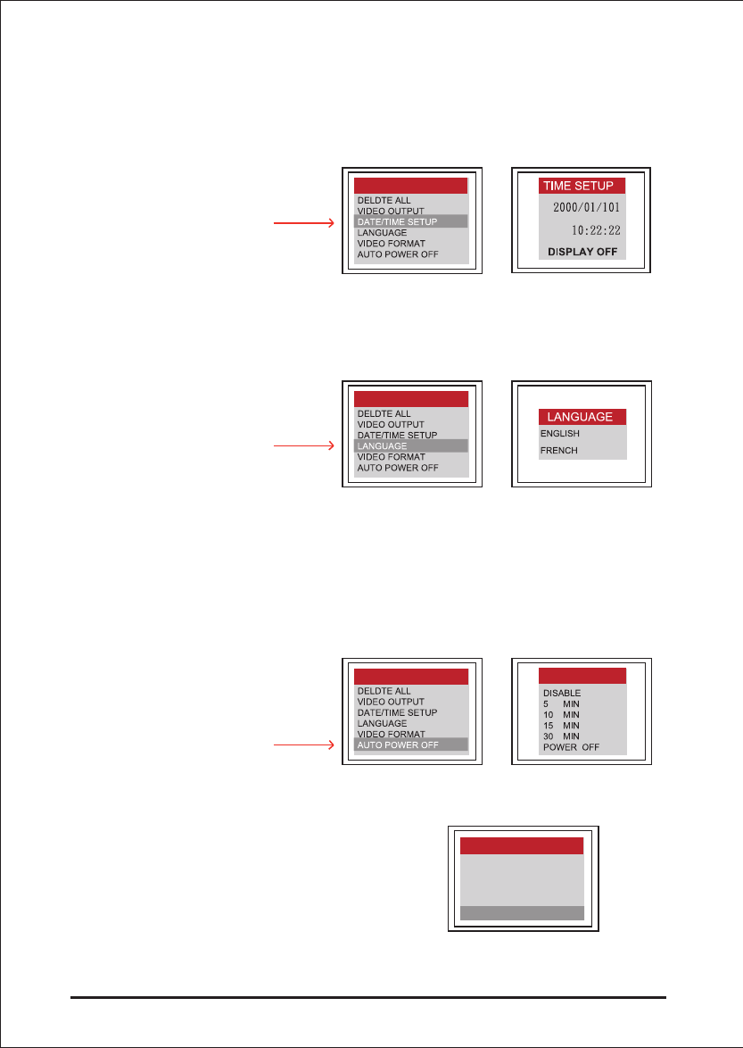
Language
Navigate to LANGUAGE in the menu, press the OK button. Select the required language
using the UP or DOWN buttons and confirm with the OK button.
Video Format
Navigate to VIDEO FORMAT in the menu, press the OK button. Select the required video
format (NTSC or PAL) using the UP or DOWN buttons. Confirm with the OK button.
Auto Power Off
Navigate to AUTO POWER OFF in the menu, press the OK button. Select the required
auto power off time (5, 10, 15, 30 minutes or Disable) using the UP or DOWN buttons.
Confirm with the OK button.
7
VIDEO SCOPE
Date/Time Set up
Press UP button & DOWN button to select year/month/day or hour/minute/second. Press
PHOTO button to increase the value and the REC button to decrease the value.
The date and time can be displayed in the preview image mode. Use either the PHOTO or
REC button to toggle between display “ON” and “OFF”:
Wireless Inspection Device Operation
In the Menu page, press the OK button while
the INPUT SOURCE slot is selected.
MENU
MENU
MENU
DATE/TIME SETUP
LANGUAGE
VIDEO FORMAT
AUTO POWER OFF
INPUT SOURCE
MENU
AUTO OFF
8VIDEO SCOPE
4. Digital Zoom
The picture in preview mode could be magnificated by the user as themselves wish.
The zoom ratio is two times. Press Zoom in button and Zoom out button to select ratio from
1.0 to 2.0 divided by each 0.1 difference.
Press the OK button while the WIRELESS
slot is selected.
Connect the insertion tube to the wireless handle unit as shown in the figure and tighten the
locking collar.
Press the POWER button of the
wireless handle unit to start the wireless
inspection.
Press the button of the wireless
handle unit to adjust the insertion cable LED
brightness.
DIRECT
WIRELESS
INPUT SOURCE
9
VIDEO SCOPE
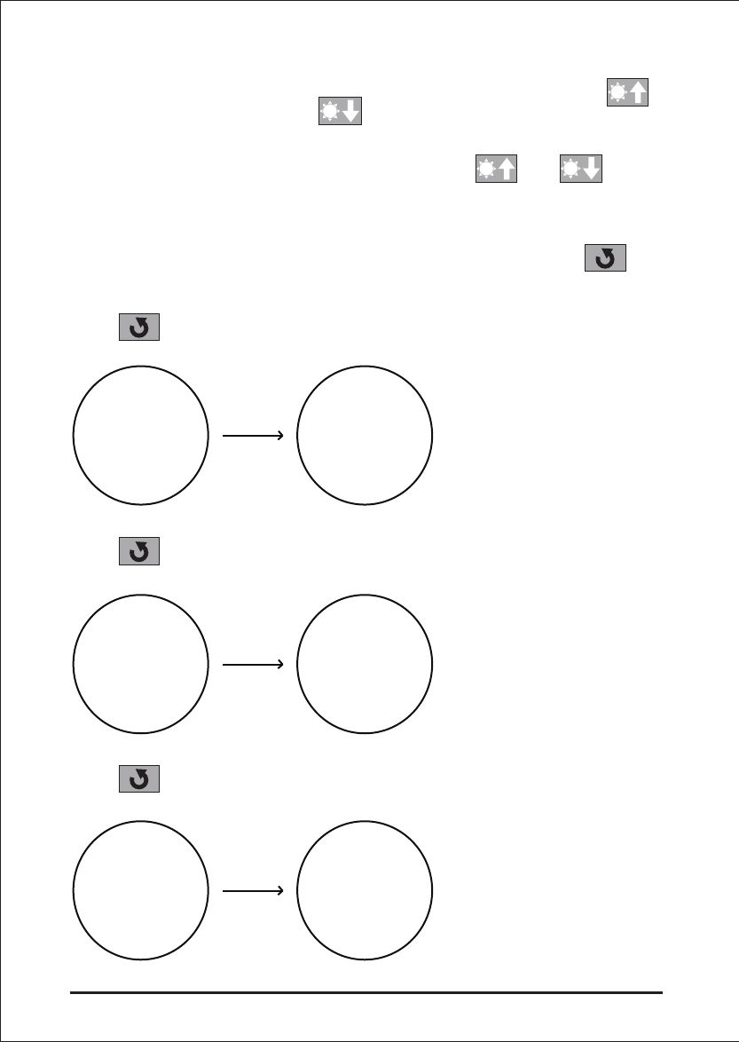
6. Mirror / Reflecting Object Surface
The Wireless Video Scope have the mirror image function. When you press the button,
you can get a mirrored image to original image. The phenomenon is shown as follows:
Press button first time:
Press button second time:
Press button third time:
5. LED Adjustment
This function is designed for user adjusting the brightness of LED to choose
a suitable illumination condition for different environment. The button
is for increasing brightness and is for decreasing brightness.
Note:Adjust the insertion cable LED brightness with and button
of the wireless handle unit during Wireless Inspection System operation.
G
G
G
G
G
G
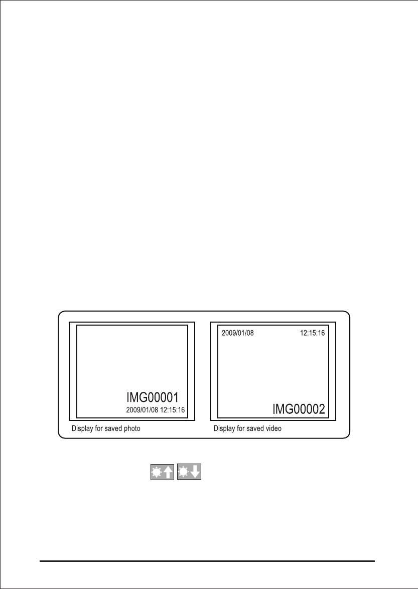
8. Surfing mode
In the preview mode, press the UP or DOWN key, the last photo or video will be displayed.
Press the UP or DOWN keys to navigate to the photo or video to be viewed.
To stop recording, press the REC button again. The video icon disappears. The display
reverts to preview mode.
The video is automatically stored to the SD card in avi format with a file name of running
number.
For example IMG00002.avi.
To play the video, press the REC button. Press the REC button again to pause, and adjust
the video volume by pressing button.
To revert to preview mode, press the ESC button
To delete a saved photo, press the OK button whilst it is displayed. To delete a saved video,
make sure the video is not in play mode, press the OK button. A delete menu will show.
Toggle between the Yes and No options using the UP and DOWN buttons. Press the OK
button to confirm.
10 VIDEO SCOPE
7. Snapshot and Recording functions
Snapshot
In preview mode, press the PHOTO button to take a photo.
The photo is stored to the SD card in jpg format with a file name of running number. For
example IMG00001.jpg.
Recording
In preview mode, press the REC button to take a video. The video icon is shown in the
top right corner.
Users can capture the picture that they wanted during the video playing and recording by
pressing the PHOTO bottom
11
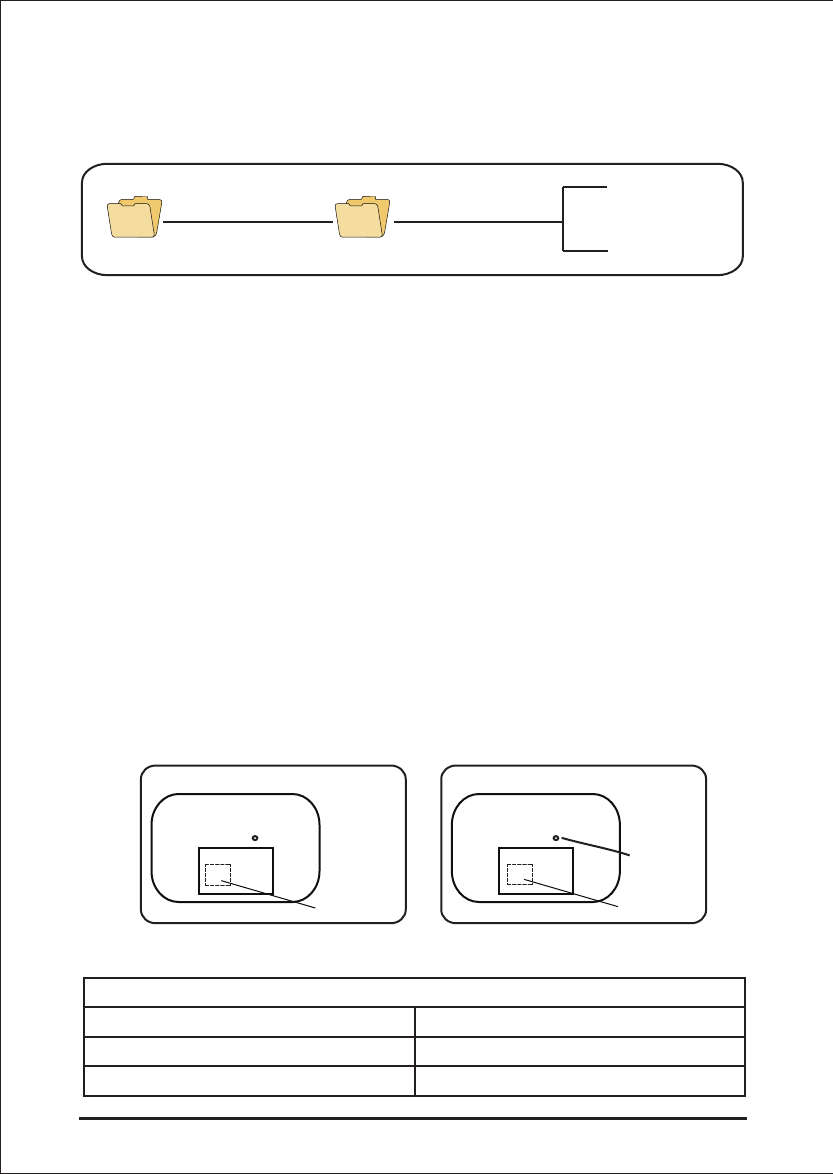
9. Transferring Photos and Videos to a PC
The computer must be running MS WindowsTM 2000 or later.
Turn the Video scope on. Connect the USB cable to the scope unit and the computer.
Look for the drive with the SD card files, this should look similar to the following figure:
The files can then transferred and viewed on the PC. In general, on a PC running MS
WindowsTM 2000 or later with WindowsTM Media player, no special software is required
to display JPG and AVI files.
10. Troubleshooting
No image on the display after turning the power on:
Battery is exhausted. Connect the scope unit to the power adapter supplied and recharge
batteries. The Video scope can be used when connected to ac power.
No image, only words on the LCD monitor after turning the power on:
Check that the insertion tube is correctly connected to the display unit.
Unable to take photos or record video:
SD card not present, wrongly inserted, full or faulty. Check SD card is present, check SD
card insertion, check SD capacity, check if SD card is faulty (check if SD card works in
other devices).
Shut down:
When all functions freeze or fail, insert an insulated needle into the hole on the back of
the main unit. The system will restart automatically.
Insertion Tube & Light Source
Image Sensor CMOS Image Sensor
Resolution (Dynamic / Static) 320 (H) X 240 (V) / 640 (H) X 480 (V)
Size Tip (Insertion Tube ) Diameter 5.5 mm / 4.0 mm(optional)
VIDEO SCOPE
IMG00001.JPG
IMG00002.AVI
100DSCIMDCIM
11. Technical data
Back
Battery
RESET
Back
Battery

12 VIDEO SCOPE
Wireless Inspection System
Tube length 1 M & Up
Field of View (FOV) 54 º / 56 º
Depth of View (DOV) 1.5 cm - 5 cm (OD 5.5mm/OD 4.0mm)
Light Source 4 LEDs (OD 5.5mm/OD 4.0mm)
Probe Working Temperature -20 to 60 °C (OD 5.5mm/OD 4.0mm)
Ingress Protection IP57 (OD 5.5mm/OD 4.0mm)
Display Unit
Power DC5V
Display 3.5” TFT LCD Monitor 320 X 240 Pixels
Interface Mini USB 1.1/ AV out
Battery (not user serviceable) Rechargeable Li-Polymer Battery (3.7V)
Power adapter 100 - 240V AC in / 5.5V DC out.
Video Out Format NTSC & PAL
Recording medium SD card
Compression Format MPEG4
Still Image Storage Format JPEG (640 X 480)
Video Recording Format AVI (640 X 480)
Working & Storage/Battery charging
temperature range
-20 °C to 60 °C /0 to 40 °C
Functions Snapshot, Video recording, Picture & video
review on LCD screen, TV Out, transfer of
picture & video from SD card to PC
Digital Zoom, Reflecting, Wireless
Insplection System
Transmitter
Type
Data
Video System
Audio type
Operation temperature
Storage temperature
RF 2.4GH
Video/Audio
NTSC/PAL
Stereo
-10~60°C
-40~80°C

13
VIDEO SCOPE
12. Spares & accessories(Optional)
(1)90 ° side view camera tube
(2)Gooseneck tube
(4)90 ° mirror adapter
(3)70 ° mirror adapter
(5)110 ° mirror adapter
(6)Magnet
(7)Guide Ball
(8)1 meter tube
(9)2 meter tube
(9)3 meter tube
(9)5 meter tube
(10)10 meter tube
(11)20 meter tube
(12)30 meter tube
For more information, please contact your dealer.
Receiver
Type
Sensitivity:
Data
Video System
Audio type
Operation temperature
Storage temperature
RF 2.4GH
Video/Audio
NTSC/PAL
Stereo
-10~60°C
-40~80°C
-87dBm(SNR=42dB, Fmod=15kHz)