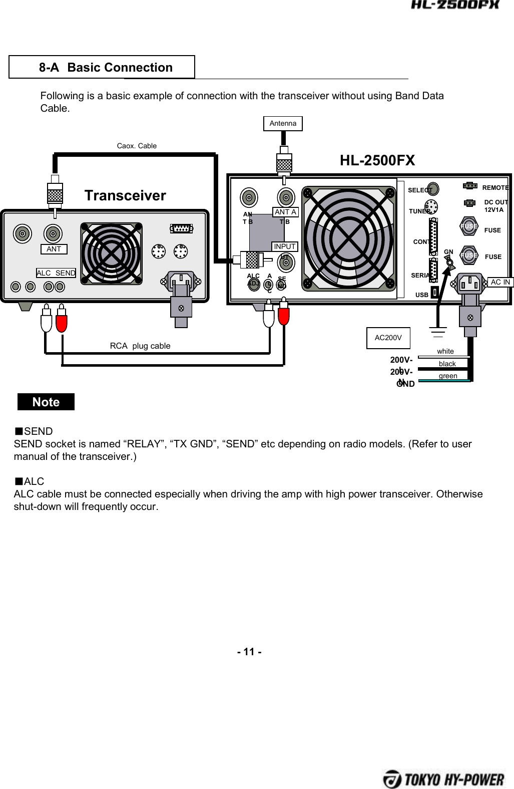
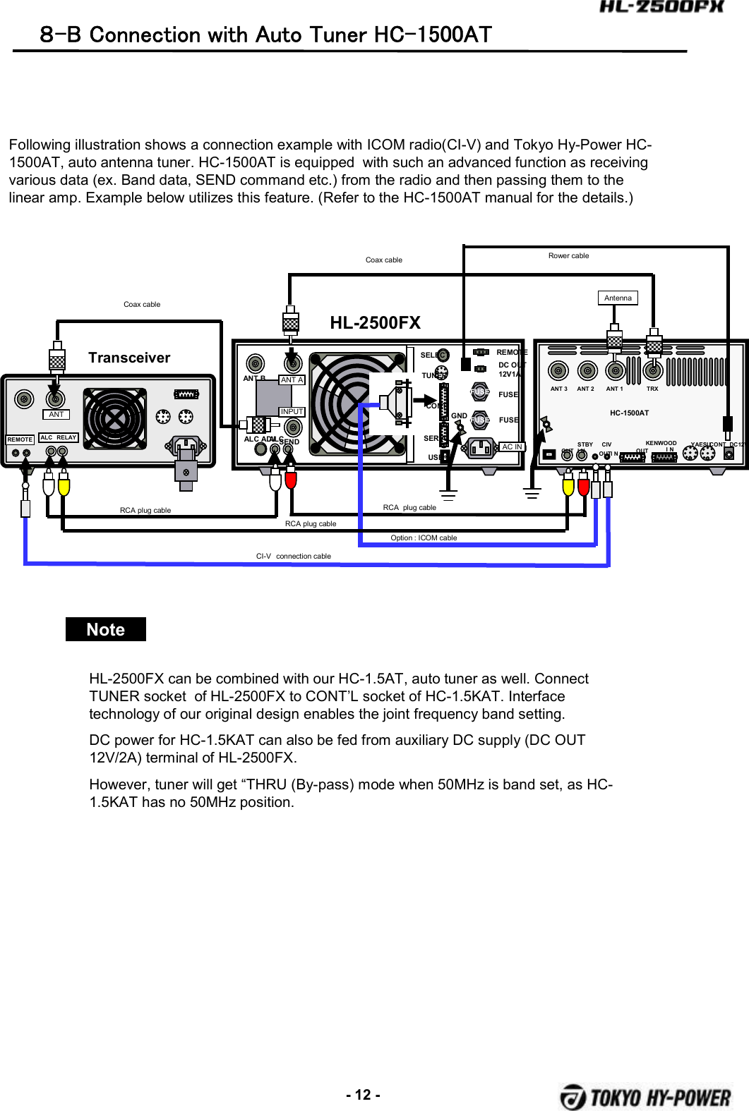
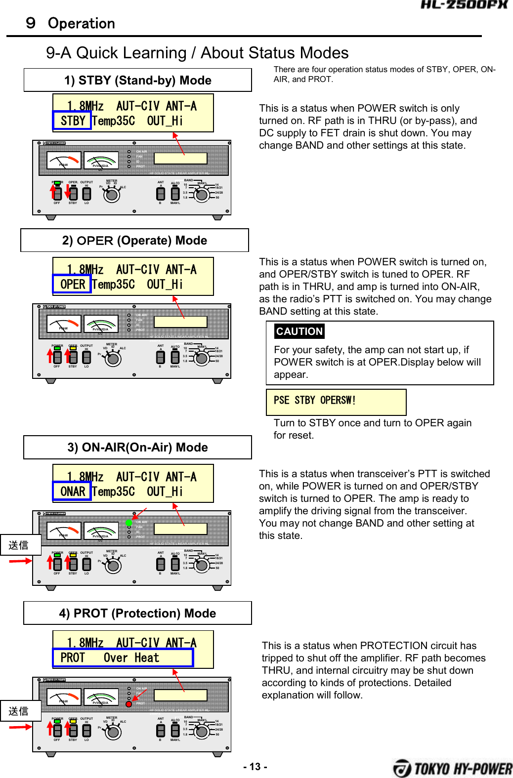
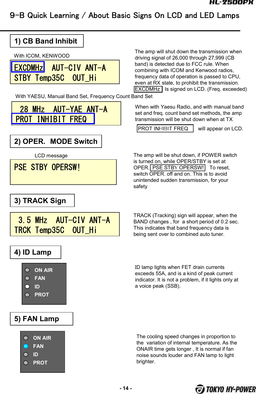
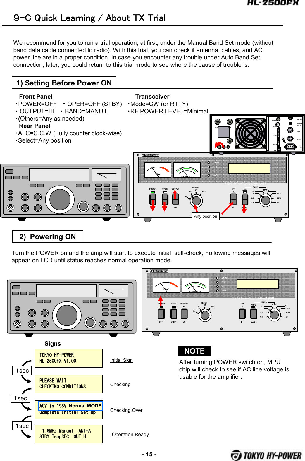
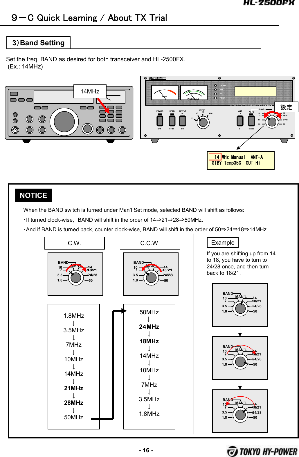
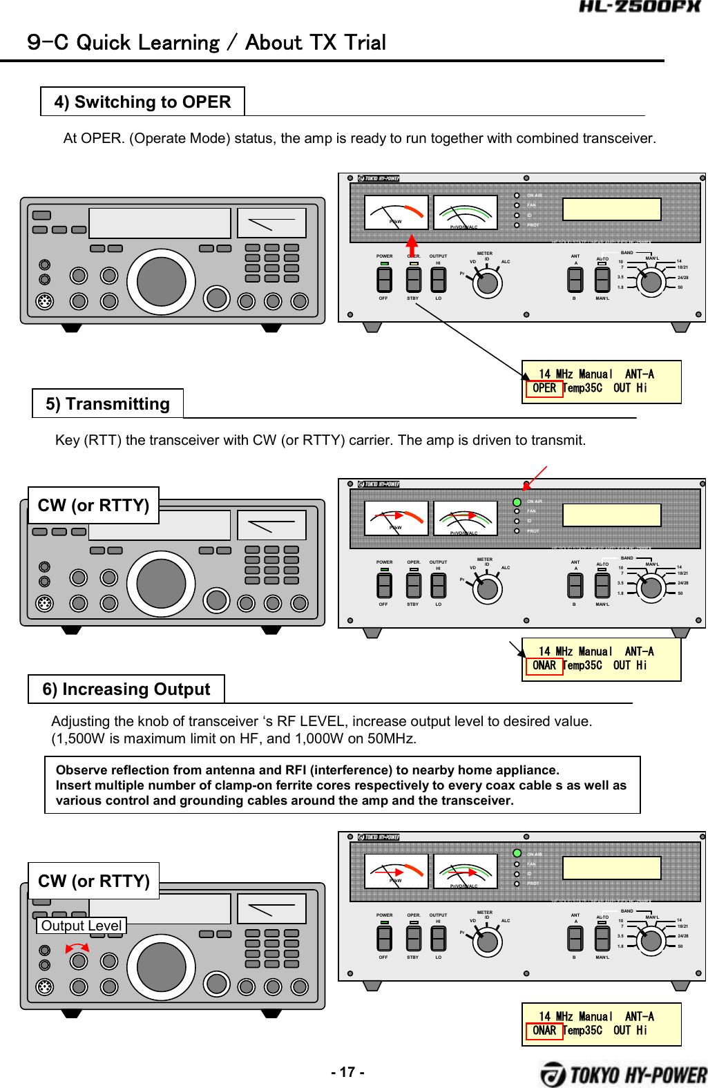
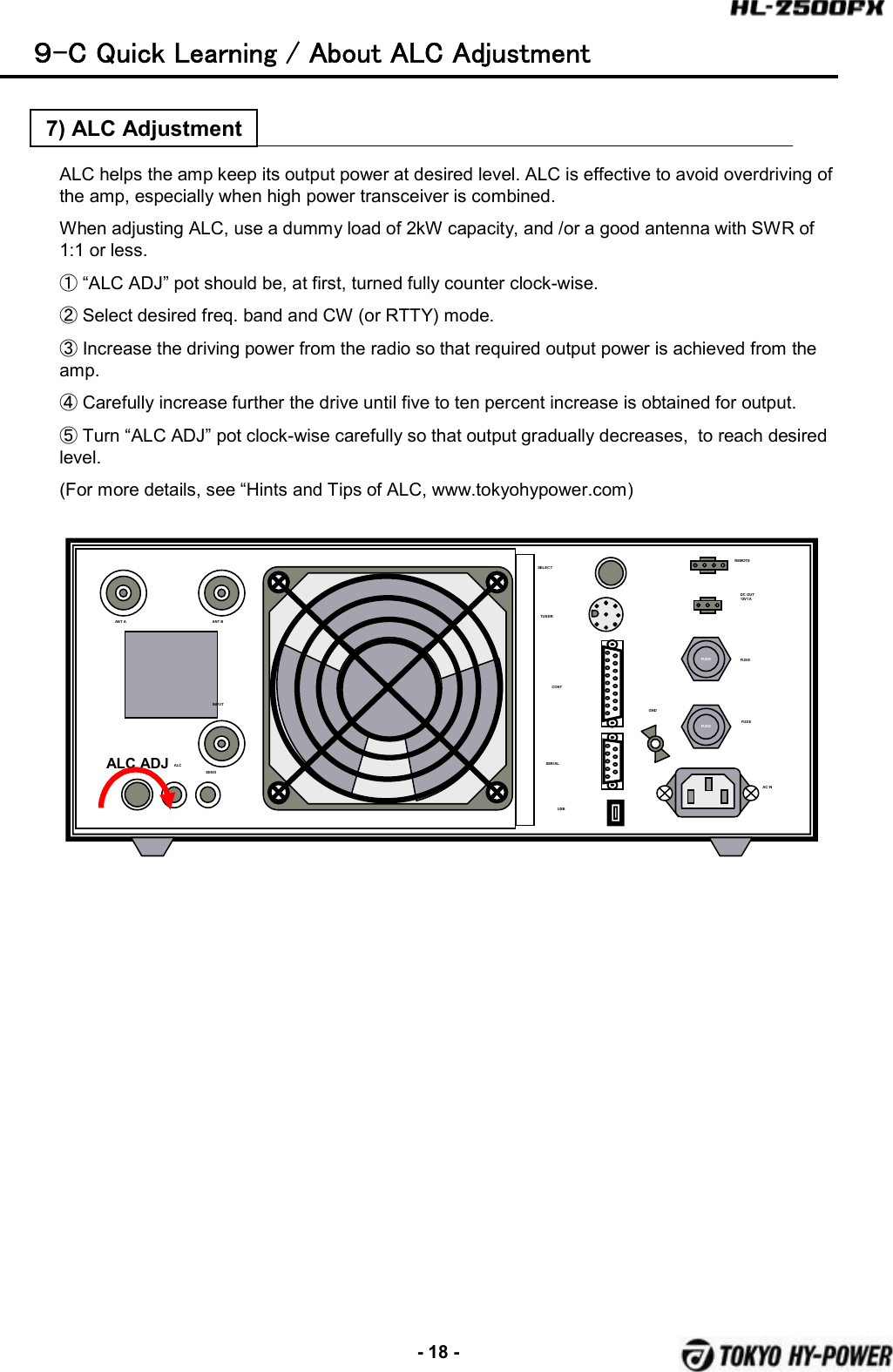
Tokyo Hy Power Labs HL-2500FX HF 50 MHz LINEAR POWER AMPLIFIER User Manual
Tokyo Hy-Power Labs, Inc. HF 50 MHz LINEAR POWER AMPLIFIER
UserManual.wiki
>
Tokyo Hy Power Labs
>
HL 2500FX User Manual
User Manual
Navigation menu
Upload a User Manual
Namespaces
Wiki Guide
HTML
PDF
Info
Views
User Manual
Discussion / Help
Navigation
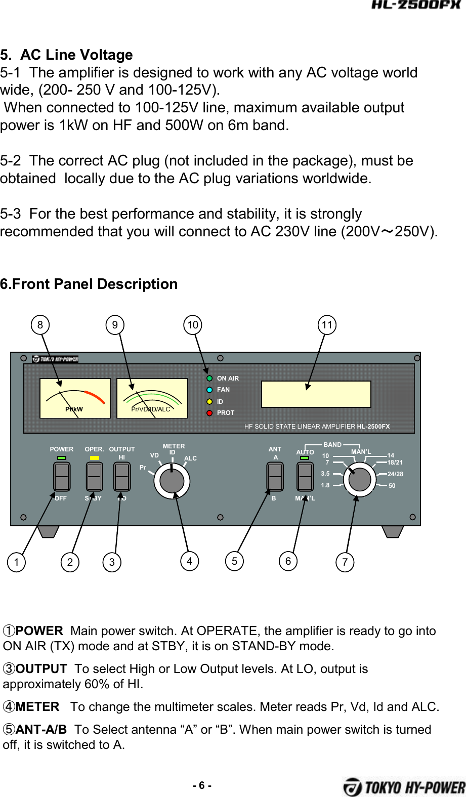
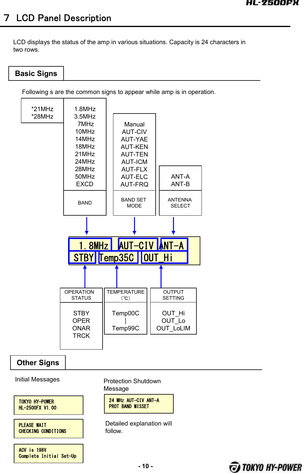
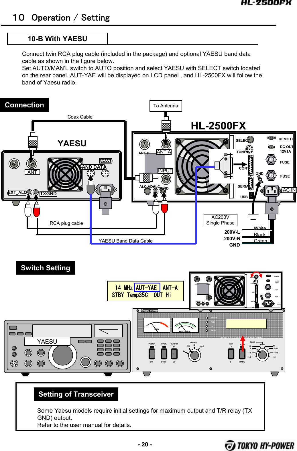
![-19 -POWER OPER. METERPrVD ALCOFF STBYBANDAUTOMAN’LON AIRFANIDPROTPf/kWHF SOLID STATE LINEAR AMPLIFIER HL-2500FXMAN’L1.83.5710 1418/2124/2850Pr/VD/ID/ALCOUTPUTHILOANTABID10 Operation / Setting10-A With ICOM (CI-V)Connect twin RCA plug cable (included in the package), and optional ICOM band data cable as shown in the figure below.Set AUTO/MAN’L switch to AUTO position and select ICOM with SELECT switch located on the rear panel. AUTO-CIV will be displayed on LCD panel.Set the CI-V menu of ICOM radio as shown below, and HL-2500FX will follow the band of ICOM radio.FUSEFUSEANT A ANT BINPUTALC ADJ ALC SENDTUNERSELECTAC INFUSEFUSEREMOTEDCOUT12V1 ACONTSERIALUSBGND14 MHz AUT-CIV ANT-A STBY Temp35C OUT HiICOMCI-V BAUD RATE: 9600 [bps]CI-V ADDRESS: 5ChCI-V Transceiver: ONCI-V with IC-731: OFF※Refer to ICOM’s instruction manual for CI-V details.Setting of ICOM CI-V MenuFUSEFUSEANT A ANT AINPUTALC ADJALCSENDTUNERSELECTAC INFUSEFUSEREMOTEDC OUT12V1ACONTSERIALUSBGNDTo AntennaANT BINPUTAC INANTAC200VSingle Phase200V-L200V-NGNDWhiteBlackGreenALC RELAYICOM TransceiverHL-2500FXCoax CableRCS plug cableREMOTE(Option) ICOM Band CableConnectionSwitch Setting](https://usermanual.wiki/Tokyo-Hy-Power-Labs/HL-2500FX/User-Guide-2020926-Page-20.png)
![-21 -POWER OPER. METERPrVD ALCOFF STBYBANDAUTOMAN’LON AIRFANIDPROTPf/kWHF SOLID STATE LINEAR AMPLIFIER HL-2500FXMAN’L1.83.5710 1418/2124/2850Pr/VD/ID/ALCOUTPUTHILOANTABID10 Operation / Setting10-C With KENWOODPrepare a control cable for PTT(SEND) and ALC. One end should be DIN plug for REMOTE of Kenwood radio. The other end should be two RCA jacks of the amp. (Refer to Kenwood manual for REMOTE socket pin assignment.)Set AUTO/MAN’L switch to AUTO position and select KENWOOD with SELECT switch located on the rear panel. AUT-KEN will be displayed on the LCD panel, and HL-2500FX will follow the band of Kenwood radio.FUSEFUSEANT A ANT BINPUTALC ADJ ALC SENDTUNERSELECTAC INFUSEFUSEREMOTEDC OUT12V1 ACONTSERIALUSBGND14 MHz AUT-KEN ANT-A STBY Temp35C OUT HiKENWOODBaud Rate :9600[bps]Stop Bit :1bit※Refer to Kenwood manual for details.Setting of TransceiverConnectionSwitch SettingFUSEFUSEANT B ANT AINPUTALC ADJALCSENDTUNERSELECTAC INFUSEFUSEREMOTEDC OUT12V1ACONTSERIALUSBGNDTo AntennaANT AINPUTAC INANTAC200VSingle Phase200V-L200V-NGNDWhiteBlackGreenTXGNDトランシーバHL-2500FXCoax CableRCA Plug Cable (ALC/SEND)(Not included)Band Data CableEXT_ALCREMOTECOM](https://usermanual.wiki/Tokyo-Hy-Power-Labs/HL-2500FX/User-Guide-2020926-Page-22.png)